JP6221908B2 - Fuel tank lid and fuel pump module having the same - Google Patents
Fuel tank lid and fuel pump module having the same Download PDFInfo
- Publication number
- JP6221908B2 JP6221908B2 JP2014075688A JP2014075688A JP6221908B2 JP 6221908 B2 JP6221908 B2 JP 6221908B2 JP 2014075688 A JP2014075688 A JP 2014075688A JP 2014075688 A JP2014075688 A JP 2014075688A JP 6221908 B2 JP6221908 B2 JP 6221908B2
- Authority
- JP
- Japan
- Prior art keywords
- fuel tank
- fuel
- lid
- side wall
- drive circuit
- Prior art date
- Legal status (The legal status is an assumption and is not a legal conclusion. Google has not performed a legal analysis and makes no representation as to the accuracy of the status listed.)
- Active
Links
Images


Classifications
-
- B—PERFORMING OPERATIONS; TRANSPORTING
- B60—VEHICLES IN GENERAL
- B60K—ARRANGEMENT OR MOUNTING OF PROPULSION UNITS OR OF TRANSMISSIONS IN VEHICLES; ARRANGEMENT OR MOUNTING OF PLURAL DIVERSE PRIME-MOVERS IN VEHICLES; AUXILIARY DRIVES FOR VEHICLES; INSTRUMENTATION OR DASHBOARDS FOR VEHICLES; ARRANGEMENTS IN CONNECTION WITH COOLING, AIR INTAKE, GAS EXHAUST OR FUEL SUPPLY OF PROPULSION UNITS IN VEHICLES
- B60K15/00—Arrangement in connection with fuel supply of combustion engines or other fuel consuming energy converters, e.g. fuel cells; Mounting or construction of fuel tanks
- B60K15/03—Fuel tanks
- B60K15/035—Fuel tanks characterised by venting means
-
- F—MECHANICAL ENGINEERING; LIGHTING; HEATING; WEAPONS; BLASTING
- F02—COMBUSTION ENGINES; HOT-GAS OR COMBUSTION-PRODUCT ENGINE PLANTS
- F02M—SUPPLYING COMBUSTION ENGINES IN GENERAL WITH COMBUSTIBLE MIXTURES OR CONSTITUENTS THEREOF
- F02M37/00—Apparatus or systems for feeding liquid fuel from storage containers to carburettors or fuel-injection apparatus; Arrangements for purifying liquid fuel specially adapted for, or arranged on, internal-combustion engines
- F02M37/04—Feeding by means of driven pumps
- F02M37/08—Feeding by means of driven pumps electrically driven
- F02M37/10—Feeding by means of driven pumps electrically driven submerged in fuel, e.g. in reservoir
- F02M37/103—Mounting pumps on fuel tanks
-
- B—PERFORMING OPERATIONS; TRANSPORTING
- B60—VEHICLES IN GENERAL
- B60K—ARRANGEMENT OR MOUNTING OF PROPULSION UNITS OR OF TRANSMISSIONS IN VEHICLES; ARRANGEMENT OR MOUNTING OF PLURAL DIVERSE PRIME-MOVERS IN VEHICLES; AUXILIARY DRIVES FOR VEHICLES; INSTRUMENTATION OR DASHBOARDS FOR VEHICLES; ARRANGEMENTS IN CONNECTION WITH COOLING, AIR INTAKE, GAS EXHAUST OR FUEL SUPPLY OF PROPULSION UNITS IN VEHICLES
- B60K15/00—Arrangement in connection with fuel supply of combustion engines or other fuel consuming energy converters, e.g. fuel cells; Mounting or construction of fuel tanks
- B60K15/03—Fuel tanks
- B60K15/04—Tank inlets
- B60K15/05—Inlet covers
-
- F—MECHANICAL ENGINEERING; LIGHTING; HEATING; WEAPONS; BLASTING
- F02—COMBUSTION ENGINES; HOT-GAS OR COMBUSTION-PRODUCT ENGINE PLANTS
- F02D—CONTROLLING COMBUSTION ENGINES
- F02D33/00—Controlling delivery of fuel or combustion-air, not otherwise provided for
- F02D33/003—Controlling the feeding of liquid fuel from storage containers to carburettors or fuel-injection apparatus ; Failure or leakage prevention; Diagnosis or detection of failure; Arrangement of sensors in the fuel system; Electric wiring; Electrostatic discharge
-
- F—MECHANICAL ENGINEERING; LIGHTING; HEATING; WEAPONS; BLASTING
- F02—COMBUSTION ENGINES; HOT-GAS OR COMBUSTION-PRODUCT ENGINE PLANTS
- F02M—SUPPLYING COMBUSTION ENGINES IN GENERAL WITH COMBUSTIBLE MIXTURES OR CONSTITUENTS THEREOF
- F02M25/00—Engine-pertinent apparatus for adding non-fuel substances or small quantities of secondary fuel to combustion-air, main fuel or fuel-air mixture
- F02M25/08—Engine-pertinent apparatus for adding non-fuel substances or small quantities of secondary fuel to combustion-air, main fuel or fuel-air mixture adding fuel vapours drawn from engine fuel reservoir
-
- F—MECHANICAL ENGINEERING; LIGHTING; HEATING; WEAPONS; BLASTING
- F02—COMBUSTION ENGINES; HOT-GAS OR COMBUSTION-PRODUCT ENGINE PLANTS
- F02M—SUPPLYING COMBUSTION ENGINES IN GENERAL WITH COMBUSTIBLE MIXTURES OR CONSTITUENTS THEREOF
- F02M37/00—Apparatus or systems for feeding liquid fuel from storage containers to carburettors or fuel-injection apparatus; Arrangements for purifying liquid fuel specially adapted for, or arranged on, internal-combustion engines
- F02M37/0076—Details of the fuel feeding system related to the fuel tank
- F02M37/0082—Devices inside the fuel tank other than fuel pumps or filters
-
- F—MECHANICAL ENGINEERING; LIGHTING; HEATING; WEAPONS; BLASTING
- F02—COMBUSTION ENGINES; HOT-GAS OR COMBUSTION-PRODUCT ENGINE PLANTS
- F02M—SUPPLYING COMBUSTION ENGINES IN GENERAL WITH COMBUSTIBLE MIXTURES OR CONSTITUENTS THEREOF
- F02M37/00—Apparatus or systems for feeding liquid fuel from storage containers to carburettors or fuel-injection apparatus; Arrangements for purifying liquid fuel specially adapted for, or arranged on, internal-combustion engines
- F02M37/04—Feeding by means of driven pumps
- F02M37/08—Feeding by means of driven pumps electrically driven
- F02M37/10—Feeding by means of driven pumps electrically driven submerged in fuel, e.g. in reservoir
-
- H—ELECTRICITY
- H02—GENERATION; CONVERSION OR DISTRIBUTION OF ELECTRIC POWER
- H02K—DYNAMO-ELECTRIC MACHINES
- H02K5/00—Casings; Enclosures; Supports
- H02K5/04—Casings or enclosures characterised by the shape, form or construction thereof
- H02K5/22—Auxiliary parts of casings not covered by groups H02K5/06-H02K5/20, e.g. shaped to form connection boxes or terminal boxes
- H02K5/225—Terminal boxes or connection arrangements
-
- B—PERFORMING OPERATIONS; TRANSPORTING
- B60—VEHICLES IN GENERAL
- B60K—ARRANGEMENT OR MOUNTING OF PROPULSION UNITS OR OF TRANSMISSIONS IN VEHICLES; ARRANGEMENT OR MOUNTING OF PLURAL DIVERSE PRIME-MOVERS IN VEHICLES; AUXILIARY DRIVES FOR VEHICLES; INSTRUMENTATION OR DASHBOARDS FOR VEHICLES; ARRANGEMENTS IN CONNECTION WITH COOLING, AIR INTAKE, GAS EXHAUST OR FUEL SUPPLY OF PROPULSION UNITS IN VEHICLES
- B60K15/00—Arrangement in connection with fuel supply of combustion engines or other fuel consuming energy converters, e.g. fuel cells; Mounting or construction of fuel tanks
- B60K15/03—Fuel tanks
- B60K2015/03236—Fuel tanks characterised by special filters, the mounting thereof
-
- B—PERFORMING OPERATIONS; TRANSPORTING
- B60—VEHICLES IN GENERAL
- B60K—ARRANGEMENT OR MOUNTING OF PROPULSION UNITS OR OF TRANSMISSIONS IN VEHICLES; ARRANGEMENT OR MOUNTING OF PLURAL DIVERSE PRIME-MOVERS IN VEHICLES; AUXILIARY DRIVES FOR VEHICLES; INSTRUMENTATION OR DASHBOARDS FOR VEHICLES; ARRANGEMENTS IN CONNECTION WITH COOLING, AIR INTAKE, GAS EXHAUST OR FUEL SUPPLY OF PROPULSION UNITS IN VEHICLES
- B60K15/00—Arrangement in connection with fuel supply of combustion engines or other fuel consuming energy converters, e.g. fuel cells; Mounting or construction of fuel tanks
- B60K15/03—Fuel tanks
- B60K15/04—Tank inlets
- B60K2015/0458—Details of the tank inlet
-
- F—MECHANICAL ENGINEERING; LIGHTING; HEATING; WEAPONS; BLASTING
- F02—COMBUSTION ENGINES; HOT-GAS OR COMBUSTION-PRODUCT ENGINE PLANTS
- F02M—SUPPLYING COMBUSTION ENGINES IN GENERAL WITH COMBUSTIBLE MIXTURES OR CONSTITUENTS THEREOF
- F02M37/00—Apparatus or systems for feeding liquid fuel from storage containers to carburettors or fuel-injection apparatus; Arrangements for purifying liquid fuel specially adapted for, or arranged on, internal-combustion engines
- F02M37/04—Feeding by means of driven pumps
- F02M37/08—Feeding by means of driven pumps electrically driven
- F02M2037/082—Details of the entry of the current supply lines into the pump housing, e.g. wire connectors, grommets, plugs or sockets
-
- F—MECHANICAL ENGINEERING; LIGHTING; HEATING; WEAPONS; BLASTING
- F02—COMBUSTION ENGINES; HOT-GAS OR COMBUSTION-PRODUCT ENGINE PLANTS
- F02M—SUPPLYING COMBUSTION ENGINES IN GENERAL WITH COMBUSTIBLE MIXTURES OR CONSTITUENTS THEREOF
- F02M37/00—Apparatus or systems for feeding liquid fuel from storage containers to carburettors or fuel-injection apparatus; Arrangements for purifying liquid fuel specially adapted for, or arranged on, internal-combustion engines
- F02M37/04—Feeding by means of driven pumps
- F02M37/08—Feeding by means of driven pumps electrically driven
- F02M2037/085—Electric circuits therefor
Landscapes
- Engineering & Computer Science (AREA)
- Chemical & Material Sciences (AREA)
- Combustion & Propulsion (AREA)
- Mechanical Engineering (AREA)
- General Engineering & Computer Science (AREA)
- Life Sciences & Earth Sciences (AREA)
- Sustainable Development (AREA)
- Sustainable Energy (AREA)
- Transportation (AREA)
- Power Engineering (AREA)
- Cooling, Air Intake And Gas Exhaust, And Fuel Tank Arrangements In Propulsion Units (AREA)
Description
本発明は、蓋部と、蓋部にインサート成形されたターミナルと、を備える燃料タンク蓋、および、それを有する燃料ポンプモジュールに関するものである。 The present invention relates to a fuel tank lid that includes a lid portion and a terminal that is insert-molded in the lid portion, and a fuel pump module that includes the fuel tank lid.
従来、例えば特許文献1に示されるように、燃料タンクと、燃料タンク内に設置された燃料ポンプユニットと、燃料ポンプユニットの制御手段と、を備える燃料供給装置が提案されている。燃料供給装置は、制御手段が収納されるチャンバ、および、チャンバの開口を覆う蓋体を有する。そして蓋体の方がチャンバよりも燃料透過量が大きく設定されている。 Conventionally, as shown in Patent Document 1, for example, a fuel supply device including a fuel tank, a fuel pump unit installed in the fuel tank, and control means for the fuel pump unit has been proposed. The fuel supply device has a chamber in which the control means is accommodated, and a lid that covers the opening of the chamber. The lid has a larger fuel permeation amount than the chamber.
上記したように特許文献1に示される燃料供給装置では、蓋体の方がチャンバよりも燃料透過量が大きく設定されている。したがってチャンバ内に気化燃料が流入したとしても、蓋体を介して外部雰囲気に気化燃料を排出することができる。しかしながら気化燃料は空気よりも重いため、気化燃料はチャンバの底から溜まっていく。そのために気化燃料が蓋体と接するのはチャンバ内が気化燃料によって満たされた後となる。この間、チャンバ内に収納された制御手段は気化燃料と接触し続けることとなり、これによって制御手段にダメージが生じる虞がある。 As described above, in the fuel supply device disclosed in Patent Document 1, the lid has a larger fuel permeation amount than the chamber. Therefore, even if vaporized fuel flows into the chamber, the vaporized fuel can be discharged to the external atmosphere via the lid. However, since vaporized fuel is heavier than air, vaporized fuel accumulates from the bottom of the chamber. For this reason, the vaporized fuel comes into contact with the lid after the chamber is filled with the vaporized fuel. During this time, the control means housed in the chamber continues to contact the vaporized fuel, which may cause damage to the control means.
そこで本発明は上記問題点に鑑み、効率よく気化燃料を外部雰囲気に排出できる燃料タンク蓋、および、それを有する燃料ポンプモジュールを提供することを目的とする。 In view of the above problems, an object of the present invention is to provide a fuel tank lid that can efficiently discharge vaporized fuel to an external atmosphere, and a fuel pump module having the fuel tank lid.
上記した目的を達成するために本発明は、燃料タンク(200)の開口部(200a)を閉塞する蓋部(10)と、燃料タンク内に設けられたポンプ(300)とポンプを駆動する駆動回路(400)とを電気的に接続するターミナル(30)と、を有し、蓋部は、燃料タンクの開口部に挿入される挿入部(11)と、燃料タンク外に位置して駆動回路を自身の中空に収納する収納部(12)と、を有し、ターミナルは、その中央部(31)が挿入部と収納部における樹脂材料から成る部位それぞれによって被覆保護され、一端(32)が燃料タンク内にてポンプと接続され、他端(33)が収納部の中空にて駆動回路と接続されており、収納部は、環状の側壁部(13)と、側壁部の2つの開口部の内、鉛直上方に位置する第1開口部を閉塞する上閉塞部(14)と、側壁部の2つの開口部の内、鉛直下方に位置する第2開口部を閉塞する下閉塞部(15)と、を有し、上閉塞部よりも鉛直下方に位置する、ターミナルと蓋部との界面を伝って収納部の中空内に侵入した気化燃料を外部雰囲気に排出する排出構造(50)を有することを特徴とする。 In order to achieve the above object, the present invention provides a lid (10) for closing the opening (200a) of the fuel tank (200), a pump (300) provided in the fuel tank, and a drive for driving the pump. And a terminal (30) for electrically connecting the circuit (400), the lid portion being inserted into the opening of the fuel tank (11), and a drive circuit located outside the fuel tank And the terminal is covered and protected by a portion made of a resin material in the insertion portion and the storage portion, and one end (32) of the terminal. The fuel tank is connected to a pump, and the other end (33) is connected to a drive circuit through a hollow portion of the storage portion. The storage portion includes an annular side wall portion (13) and two openings in the side wall portion. Close the first opening located vertically above An upper closing portion (14) that has a lower closing portion (15) that closes a second opening portion that is located vertically below the two opening portions of the side wall portion, and is vertically lower than the upper closing portion. It has the discharge structure (50) which discharges the vaporized fuel which penetrate | invaded into the hollow of the accommodating part along the interface of a terminal and a cover part located in (2).
気化燃料は空気よりも重いために収納部(12)の下閉塞部(15)から上閉塞部(14)へと溜まっていく。これに対して本発明では、排出構造(50)が上閉塞部(14)よりも鉛直下方に位置する。したがって、排出構造(50)が上閉塞部(14)に形成された構成と比べて効率よく気化燃料を外部雰囲気に排出することができる。これにより、気化燃料のために駆動回路(400)にダメージが生じることが抑制される。 Since the vaporized fuel is heavier than air, it accumulates from the lower closing portion (15) of the storage portion (12) to the upper closing portion (14). On the other hand, in the present invention, the discharge structure (50) is positioned vertically below the upper closing part (14). Therefore, the vaporized fuel can be efficiently discharged to the external atmosphere as compared with the configuration in which the discharge structure (50) is formed in the upper closing portion (14). Thereby, damage to the drive circuit (400) due to vaporized fuel is suppressed.
駆動回路は複数の電子素子を有しており、複数の電子素子の少なくとも1つは、気化燃料との接触を避けるべく、上閉塞部に固定されている。これによれば、気化燃料と電子素子との接触を避けることができる。そのために電子素子の劣化が抑制される。 The drive circuit has a plurality of electronic elements, and at least one of the plurality of electronic elements is fixed to the upper closing portion so as to avoid contact with the vaporized fuel. According to this, contact between the vaporized fuel and the electronic element can be avoided. Therefore, the deterioration of the electronic element is suppressed.
なお、特許請求の範囲に記載の請求項、および、課題を解決するための手段それぞれに記載の要素に括弧付きで符号をつけているが、この括弧付きの符号は実施形態に記載の各構成要素との対応関係を簡易的に示すためのものであり、実施形態に記載の要素そのものを必ずしも示しているわけではない。括弧付きの符号の記載は、いたずらに特許請求の範囲を狭めるものではない。 In addition, although the elements described in the claims and the means for solving the problems are attached with parentheses, the parentheses are attached to each component described in the embodiment. This is to simply show the correspondence with the elements, and does not necessarily indicate the elements themselves described in the embodiments. The description of the reference numerals with parentheses does not unnecessarily narrow the scope of the claims.
以下、本発明の実施形態を図に基づいて説明する。
(第1実施形態)
図1〜図4に基づいて、本実施形態に係る燃料タンク蓋を説明する。以下においては互いに直交の関係にある3方向を、x方向、y方向、z方向と示す。本実施形態ではz方向が鉛直方向に沿い、x方向とy方向とによって規定されるx−y平面が水平面に沿っている。
Hereinafter, embodiments of the present invention will be described with reference to the drawings.
(First embodiment)
The fuel tank lid according to the present embodiment will be described based on FIGS. Hereinafter, the three directions orthogonal to each other are referred to as an x direction, a y direction, and a z direction. In the present embodiment, the z direction is along the vertical direction, and the xy plane defined by the x direction and the y direction is along the horizontal plane.
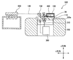
図1に示すように燃料タンク蓋100は、車両に搭載される燃料ポンプモジュール500の構成要素の1つである。燃料ポンプモジュール500は、燃料タンク蓋100と、フランジ110と、燃料タンク200と、ポンプ300と、駆動回路400と、を有する。燃料タンク200は自身の中空に燃料を貯留するものであり、その開口部200aが燃料タンク蓋100およびフランジ110によって閉塞されている。ポンプ300は燃料を内燃機関600に供給するものであり、燃料タンク200内に設けられている。駆動回路400はポンプ300を駆動するものであり、燃料タンク200外にて燃料タンク蓋100に搭載されている。
As shown in FIG. 1, the
図1に示すようにポンプ300と駆動回路400とは、ポンプ駆動配線310および燃料タンク蓋100の有するターミナル30を介して電気的に接続されている。そしてポンプ300によってくみ上げられた燃料は、フランジ110に設けられた燃料供給管130、および、燃料供給管130に組み付けられた燃料配管140(図1に示す破線)を介して内燃機関600に供給される。なお、燃料タンク200の開口部200aは、燃料タンク200を構成する壁部よりも鉛直上方に位置している。開口部200aの形成された上壁部の外面は水平面に沿っている。そのため、燃料タンク200内から気化した燃料(以下、気化燃料と示す)が開口部200aを介して外部雰囲気に排出されたとしても、開口部200aの周囲(燃料タンク蓋100の周囲)に気化燃料が滞ることが抑制されている。
As shown in FIG. 1, the
図2に示すように燃料タンク蓋100はフランジ110の開口部110aに設けられる。開口部110aにはOリング120が設けられており、Oリング120の外環面120aが全周に渡って開口部110aを形作るフランジ110の縁部と接触し、その内環面120bが全周に渡って燃料タンク蓋100と接触している。これによってフランジ110の開口部110aが燃料タンク蓋100とOリング120とによって閉塞されている。
As shown in FIG. 2, the
燃料タンク蓋100は、蓋部10と、ターミナル30と、排出構造50と、を有する。蓋部10はフランジ110とともに燃料タンク200の開口部200aを閉塞しつつ、駆動回路400を搭載する機能を果たす。上記したように、蓋部10はフランジ110の開口部110aを閉塞することで、燃料タンク200の開口部200aの一部を閉塞する。
The
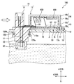
蓋部10は、開口部200a(開口部110a)に挿入される挿入部11と、燃料タンク200外に位置して駆動回路400を自身の中空に収納する収納部12と、を有する。図2に示すように、挿入部11はz方向に延びた形状を成し、収納部12は箱形状を成している。挿入部11の一部が燃料タンク200内に挿入され、残りが燃料タンク200から外部雰囲気に露出されている。そして燃料タンク200内に挿入された挿入部11とフランジ110との間に上記したOリング120が設けられ、両者の間の隙間から気化燃料が外部雰囲気に漏れることが抑制されている。
The
収納部12は環状の側壁部13と、側壁部13の2つの開口部の内、鉛直上方に位置する第1開口部を閉塞する上閉塞部14と、鉛直下方に位置する第2開口部を閉塞する下閉塞部15と、を有する。上記した挿入部11と側壁部13とは同一の樹脂材料(例えばポリフェニレンサルファイド樹脂やポリブチレンテレフタレート樹脂)から成り、挿入部11における燃料タンク200から外部雰囲気に露出された部位の側部と側壁部13の外環面とが接触する態様で、両者が機械的に連結されている。
The
側壁部13は、上閉塞部14が組み付けられる第1環状部13aと、下閉塞部15が組み付けられる第2環状部13bと、を有する。x方向における内径が、第1環状部13aのほうが第2環状部13bよりも短く、その内径差に応じた段差部13cが環状部13a,13bの連結部位に形成されている。この段差部13cとフランジ110との間に空間が構成され、段差部13cに下閉塞部15の上面の縁部が対向する態様で、下閉塞部15が第2環状部13bに組み付けられている。図2に示すように、下閉塞部15とフランジ110との間にも空間が構成されており、この空間は外部雰囲気と連通されている。また第2環状部13bにはネジ16を組み付けるためのネジ止め部17が形成されており、蓋部10はネジ16によってフランジ110にネジ止めされている。
The
上閉塞部14は銅やアルミニウムなどの金属材料から成り、駆動回路400にて発生した熱を外部雰囲気に放熱する機能を果たす。本実施形態に係る上閉塞部14は、第1環状部13aの外環面と接触する態様で第1環状部13aを囲む囲み部14aと、側壁部13の第1開口部を閉塞する天井部14bと、を有する。駆動回路400は複数の電子素子から成り、この複数の電子素子の少なくとも1つが上閉塞部14(天井部14b)に搭載されている。本実施形態では駆動回路400を構成する全ての電子素子が上閉塞部14に搭載されている。これによって、収納部12の中空内に侵入した気化燃料と駆動回路400の電子素子との接触が避けられている。
The
ターミナル30は、ポンプ300と駆動回路400とを電気的に接続するものである。ターミナル30はL字形状を成し、挿入部11と側壁部13それぞれにインサート成形されている。ターミナル30の中央部31が、挿入部11、上記した挿入部11と側壁部13の連結部位、および、側壁部13それぞれによって被覆保護され、一端32が挿入部11から燃料タンク200内に露出され、他端33が側壁部13から収納部12の中空内に露出されている。そして一端32はポンプ300と電気的に接続され、他端33は駆動回路400と電気的に接続されている。なお、駆動回路400は配線を有しており、この配線とターミナル30の他端33とが電気的に接続されている。したがって本来であれば駆動回路400の配線とターミナル30の他端33とを区別して図示するべきである。しかしながら燃料タンク100を説明する上において両者を区別する必要は格別ないので、駆動回路400の配線がターミナル30の他端33に含まれる形式にて図2では図示している。
The terminal 30 is for electrically connecting the
排出構造50は、上閉塞部14よりも鉛直下方に位置し、収納部12の中空内に侵入した気化燃料を外部雰囲気に排出するものである。図2に破線矢印で示すように、ターミナル30と蓋部10との間の界面を伝って収納部12の中空内に気化燃料が昇ってくる虞がある。すると、駆動回路400を構成する電子素子と気化燃料とが接触し、これによって電子素子が劣化する虞がある。そこで、上記した排出構造50によって、収納部12の中空内に侵入した気化燃料を外部雰囲気に排出する。
The
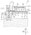
排出構造50は、下閉塞部15および側壁部13の少なくとも一方に形成された、気化燃料を外部雰囲気に排出するための排出口51を有する。本実施形態では排出口51は下閉塞部15に形成されている。燃料タンク蓋100は車両に搭載されるが、排出口51は車両の走行によって生じる走行風(図2に示す白抜き矢印)の下流に配置される。また図3に示すように、下閉塞部15には鉛直下方に凹んだ凹み部15aが形成されており、この凹み部15aに排出口51が形成されている。そして排出口51は、気化燃料を含む気体を透過し易く、液体を透過し難い呼吸フィルタ52によって覆われている。
The
本実施形態に係る排出構造50は、上記した排出口51の他に、上閉塞部14よりも気化燃料を透過し易い材料から成る接着剤53を有する。図4に示すように、接着剤53は側壁部13の段差部13cと下閉塞部15の上面の縁部との間に設けられており、側壁部13と下閉塞部15を機械的に連結している。接着剤53は、上記した凹み部15aに次いで、収納部12の中空において鉛直下方に位置している。
The
更に、本実施形態に係る排出構造50は、下閉塞部15および側壁部13の少なくとも一方における、上閉塞部14よりも気化燃料を透過し易い材料から成った部位も有する。本実施形態において下閉塞部15および側壁部13それぞれは上閉塞部14よりも気化燃料を透過し易い材料から成る。したがって、排出構造50は側壁部13および上閉塞部14それぞれを含んでいる。
Furthermore, the
次に、本実施形態に係る燃料タンク蓋100の作用効果を説明する。気化燃料は空気よりも重いために収納部12の下閉塞部15から上閉塞部14へと溜まっていく。これに対して燃料タンク蓋100では、排出構造50が上閉塞部14よりも鉛直下方に位置する。したがって、排出構造が上閉塞部に形成された構成と比べて効率よく気化燃料を外部雰囲気に排出することができる。これにより、気化燃料のために駆動回路400にダメージが生じることが抑制される。
Next, the function and effect of the
駆動回路400を構成する全ての電子素子が上閉塞部14に搭載されている。これによれば、気化燃料と電子素子との接触を避けることができる。そのために電子素子の劣化が抑制される。
All the electronic elements constituting the
燃料タンク200の開口部200aは、燃料タンク200を構成する壁部よりも鉛直上方に位置する。これによれば、燃料タンクの開口部が壁部よりも鉛直下方に位置する構成とは異なり、壁部のために開口部200aの周囲(燃料タンク蓋100の周囲)に気化燃料が滞留することが抑制される。
The opening 200 a of the
下閉塞部15に排出口51が形成されている。これによれば、排出口51を介して外部雰囲気に気化燃料を排出することができる。
A
走行風の下流に排出口51が配置されている。これによれば、排出口51から外部雰囲気に排出された気化燃料を走行風によって燃料タンク蓋100よりも遠ざけることができる。
A
排出口51は呼吸フィルタ52によって覆われている。これによれば、収納部12の中空に水などの液体が流入することが抑制される。
The
下閉塞部15に凹み部15aが形成され、凹み部15aに排出口51が形成されている。これによれば、凹み部15aに気化燃料を流入させ、それによって排出口51から気化燃料を外部雰囲気に排出することができる。
A
上閉塞部14よりも気化燃料を透過し易い材料から成る接着剤53によって下閉塞部15と側壁部13とが機械的に連結されている。これによれば、気化燃料を接着剤53を介して外部雰囲気に排出することができる。
The
接着剤53は、凹み部15aに次いで、収納部12の中空において鉛直下方に位置している。これによれば、排出口51にて気化燃料を排出し切れずに、凹み部15aよりも鉛直上方に気化燃料が貯留されたとしても、その気化燃料を接着剤53を介して外部雰囲気に排出することができる。
The adhesive 53 is positioned vertically downward in the hollow of the
下閉塞部15および側壁部13それぞれは上閉塞部14よりも気化燃料を透過し易い材料から成る。これによれば、気化燃料を下閉塞部15および側壁部13それぞれを介して外部雰囲気に排出することができる。
Each of the
(第2実施形態)
次に、本発明の第2実施形態を図5に基づいて説明する。第2実施形態に係る燃料タンク蓋は上記した実施形態によるものと共通点が多い。そのため、以下においては共通部分の説明を省略し、異なる部分を重点的に説明する。また、以下においては上記した実施形態で示した要素と同一の要素には同一の符号を付与する。
(Second Embodiment)
Next, a second embodiment of the present invention will be described with reference to FIG. The fuel tank cover according to the second embodiment has much in common with the above-described embodiment. Therefore, below, description of a common part is abbreviate | omitted and it demonstrates focusing on a different part. In the following description, the same reference numerals are given to the same elements as those described in the above embodiment.
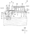
第1実施形態では、上閉塞部14が囲み部14aと天井部14bを有する例を示した。これに対し本実施形態では、上閉塞部14が天井部14bを有し、収納部12の側壁部13に流入口60が形成されたことを特徴とする。
In the first embodiment, an example in which the
流入口60は、収納部12の中空内に侵入した気化燃料を排出構造50に誘導するべく、外部雰囲気の空気を収納部12の中空内に流入させるためのものである。流入口60は排出構造50(排出口51、接着剤53、および、下閉塞部15)よりも鉛直上方に位置し、気化燃料を含む気体を透過し易く、液体を透過し難い呼吸フィルタ61によって覆われている。そして流入口60は走行風の上流に配置され、その下流に排出構造50が配置されている。これにより、流入口60から収納部12の中空に流入する走行風に駆動回路400の電子素子の少なくとも1つが晒されている。
The
これによれば、流入口がない構成とは異なり、流入口60から排出構造50に向かって気化燃料を流動させることができる。そのため、気化燃料を外部雰囲気に効率よく排出することができる。
According to this, unlike the configuration without the inlet, the vaporized fuel can flow from the
また、流入口60は排出構造50よりも鉛直上方に位置する。したがって鉛直上方に位置する流入口60から鉛直下方に位置する排出構造50に向かって気化燃料を流動させ、排出構造50を介して気化燃料を外部雰囲気に効率よく排出することができる。
Further, the
流入口は呼吸フィルタ61によって覆われている。これによれば、収納部12の中空に水などの液体が流入することが抑制される。
The inlet is covered with a
流入口60は走行風の上流に配置され、その下流に排出構造50が配置されている。これによれば、流入口60を介して収納部12の中空内に走行風を流入させ、その走行風とともに気化燃料を排出構造50を介して外部雰囲気に排出することができる。
The
駆動回路400の電子素子の少なくとも1つが走行風に晒されている。これによれば、駆動回路400に気化燃料が接触することが抑制される。
At least one of the electronic elements of the
以上、本発明の好ましい実施形態について説明したが、本発明は上記した実施形態になんら制限されることなく、本発明の主旨を逸脱しない範囲において、種々変形して実施することが可能である。 The preferred embodiments of the present invention have been described above. However, the present invention is not limited to the above-described embodiments, and various modifications can be made without departing from the spirit of the present invention.
各実施形態では、燃料タンク蓋100とフランジ110とが別体である例を示した。しかしながら、燃料タンク蓋100の蓋部10とフランジ110とが一体でもよい。この場合、燃料タンク蓋100は単体で燃料タンク200の開口部200aの全てを閉塞する。
In each embodiment, the example in which the
各実施形態では燃料タンク蓋100を主として説明したが、この燃料タンク蓋100と、上記した燃料タンク200と、駆動回路400と、ポンプ300と、を有する燃料ポンプモジュール500は、もちろん特許請求の範囲に含まれている。
In each embodiment, the
各実施形態では挿入部11と側壁部13とがポリフェニレンサルファイド樹脂やポリブチレンテレフタレート樹脂から成る例を示した。しかしながら挿入部11と側壁部13それぞれを形成する樹脂材料としては上記例に限定されない。
In each embodiment, the
各実施形態では第2環状部13bにネジ止め部17が形成され、ネジ16によって蓋部10がフランジ110にネジ止めされている例を示した。しかしながら蓋部10のフランジ110への固定構造としては上記例に限定されない。
In each embodiment, the screwing
各実施形態では駆動回路400を構成する全ての電子素子が上閉塞部14に搭載された例を示した。しかしながら駆動回路400を構成する複数の電子素子の内、特に気化燃料によって劣化しやすい電子素子のみが上閉塞部14に搭載された構成を採用することもできる。また、駆動回路400を構成する全ての電子素子が上閉塞部14ではなく、下閉塞部15や側壁部13に搭載された構成を採用することもできる。
In each embodiment, an example in which all the electronic elements constituting the
各実施形態では、排出口51が下閉塞部15に形成された例を示した。しかしながら排出口51は側壁部13に形成されていても良いし、下閉塞部15と側壁部13それぞれに形成されても良い。
In each embodiment, the example in which the
各実施形態では、燃料タンク蓋100が走行風に晒される例を示した。しかしながら燃料タンク蓋100は走行風に晒されなくとも良い。
In each embodiment, the example in which the
各実施形態では、下閉塞部15に凹み部15aが形成された例を示した。しかしながら下閉塞部15に凹み部15aは形成されていなくとも良い。したがって、凹み部15aに排出口51が形成されていなくとも良い。
In each embodiment, the example in which the recessed
各実施形態では排出口51が呼吸フィルタ52によって覆われた例を示した。しかしながら排出口51は呼吸フィルタ52によって覆われていなくとも良い。
In each embodiment, an example in which the
各実施形態では排出構造50が接着剤53を有する例を示した。しかしながら排出構造50は接着剤53を有していなくとも良く、側壁部13と下閉塞部15とが接着剤53を介して機械的に連結されていなくとも良い。例えば、側壁部13と下閉塞部15とが互いに勘合されることで機械的に連結された構成を採用することもできる。
In each embodiment, the
各実施形態では接着剤53が凹み部15aに次いで収納部12の中空において鉛直下方に位置している例を示した。しかしながら接着剤53における鉛直方向の位置としては、上閉塞部14よりも下方に位置していれば良い。
In each embodiment, the example was shown in which the adhesive 53 is positioned vertically downward in the hollow of the
各実施形態では下閉塞部15および側壁部13それぞれは上閉塞部14よりも気化燃料を透過し易い材料から成り、排出構造50は側壁部13および上閉塞部14それぞれを含んでいる例を示した。しかしながら排出構造50は側壁部13および上閉塞部14それぞれを含んでいなくとも良い。
In each embodiment, each of the
各実施形態では、図2および図5に示すように、収納部12の有する側壁部13、上閉塞部14、および、下閉塞部15それぞれが別体である例を示した。しかしながら図6に示すように、側壁部13と上閉塞部15とが一体であっても良い。また図7に示すように、側壁部13と下閉塞部14とが一体であっても良い。更に図8に示すように、側壁部13、上閉塞部14、および、下閉塞部15それぞれが一体であっても良い。
In each embodiment, as shown in FIGS. 2 and 5, the example in which the
第2実施形態では流入口60が排出構造50(排出口51、接着剤53、および、下閉塞部15)よりも鉛直上方に位置する例を示した。しかしながら流入口60は排出構造50の有する構成要素の少なくとも1つより鉛直下方に位置していても良い。
In the second embodiment, the example in which the
第2実施形態では流入口60が呼吸フィルタ61によって覆われている例を示した。しかしながら流入口60は呼吸フィルタ61によって覆われていなくとも良い。
In 2nd Embodiment, the
第2実施形態では流入口60から収納部12の中空に流入する走行風に駆動回路400の電子素子の少なくとも1つが晒された例を示した。しかしながら駆動回路400を構成する複数の電子素子の内、特に気化燃料によって劣化しやすい電子素子のみが走行風に晒された構成を採用することもできる。また、駆動回路400を構成する全ての電子素子が走行風に晒されない構成を採用することもできる。
In the second embodiment, an example in which at least one of the electronic elements of the
10・・・蓋部、11・・・挿入部、12・・・収納部、13・・・側壁部、14・・・上閉塞部、15・・・下閉塞部、30・・・ターミナル、31・・・中央部、32・・・一端、33・・・他端、50・・・排出構造、100・・・燃料タンク蓋、200・・・燃料タンク、200a・・・開口部、300・・・ポンプ、400・・・駆動回路
DESCRIPTION OF
Claims (14)
前記燃料タンク内に設けられたポンプ(300)と前記ポンプを駆動する駆動回路(400)とを電気的に接続するターミナル(30)と、を有し、
前記蓋部は、
前記燃料タンクの開口部に挿入される挿入部(11)と、
前記燃料タンク外に位置して前記駆動回路を自身の中空に収納する収納部(12)と、を有し、
前記ターミナルは、その中央部(31)が前記挿入部と前記収納部における樹脂材料から成る部位それぞれによって被覆保護され、一端(32)が前記燃料タンク内にて前記ポンプと接続され、他端(33)が前記収納部の中空にて前記駆動回路と接続されており、
前記収納部は、
環状の側壁部(13)と、
前記側壁部の2つの開口部の内、鉛直上方に位置する第1開口部を閉塞する上閉塞部(14)と、
前記側壁部の2つの開口部の内、鉛直下方に位置する第2開口部を閉塞する下閉塞部(15)と、を有し、
前記上閉塞部よりも前記鉛直下方に位置する、前記ターミナルと前記蓋部との界面を伝って前記収納部の中空内に侵入した気化燃料を外部雰囲気に排出する排出構造(50)を有することを特徴とする燃料タンク蓋。 A lid (10) for closing the opening (200a) of the fuel tank (200);
A terminal (30) for electrically connecting a pump (300) provided in the fuel tank and a drive circuit (400) for driving the pump;
The lid is
An insertion part (11) inserted into the opening of the fuel tank;
A storage part (12) which is located outside the fuel tank and stores the drive circuit in its own hollow;
The terminal has a central portion (31) covered and protected by a portion made of a resin material in the insertion portion and the storage portion, one end (32) is connected to the pump in the fuel tank, and the other end ( 33) is connected to the drive circuit in the hollow of the storage portion,
The storage section is
An annular side wall (13);
Of the two openings of the side wall, an upper closing part (14) for closing the first opening located vertically above;
A lower closing part (15) for closing a second opening located vertically below the two opening parts of the side wall part,
It has a discharge structure (50) that discharges vaporized fuel that has entered the hollow of the storage part through the interface between the terminal and the lid part, located vertically below the upper closing part, to the outside atmosphere. Fuel tank lid characterized by.
複数の前記電子素子の少なくとも1つは、前記気化燃料との接触を避けるべく、前記上閉塞部に固定されていることを特徴とする請求項1に記載の燃料タンク蓋。 The drive circuit has a plurality of electronic elements,
2. The fuel tank lid according to claim 1, wherein at least one of the plurality of electronic elements is fixed to the upper closing portion so as to avoid contact with the vaporized fuel.
前記排出口は前記呼吸フィルタによって覆われていることを特徴とする請求項3に記載の燃料タンク蓋。 A breathing filter (52) that is easy to permeate gas containing the vaporized fuel and difficult to permeate liquid;
The fuel tank lid according to claim 3, wherein the discharge port is covered with the breathing filter.
前記凹み部に前記排出口が形成されていることを特徴とする請求項3または請求項4に記載の燃料タンク蓋。 The lower closing part is formed with a recessed part (15c) recessed downward in the vertical direction,
The fuel tank lid according to claim 3 or 4, wherein the discharge port is formed in the recess.
前記車両の走行によって生じる走行風の下流に前記排出口が配置されることを特徴とする請求項3〜5いずれか1項に記載の燃料タンク蓋。 Mounted on the vehicle,
The fuel tank cover according to any one of claims 3 to 5, wherein the discharge port is arranged downstream of a traveling wind generated by the traveling of the vehicle.
前記流入口は前記呼吸フィルタによって覆われていることを特徴とする請求項9または請求項10に記載の燃料タンク蓋。 A breathing filter (61) that is easy to permeate gas containing the vaporized fuel and difficult to permeate liquid;
The fuel tank cover according to claim 9 or 10, wherein the inflow port is covered with the breathing filter.
前記車両の走行によって生じる走行風の下流に前記排出構造が配置され、上流に前記流入口が配置されていることを特徴とする請求項9〜11いずれか1項に記載の燃料タンク蓋。 Mounted on the vehicle,
The fuel tank cover according to any one of claims 9 to 11, wherein the discharge structure is disposed downstream of a traveling wind generated by traveling of the vehicle, and the inflow port is disposed upstream.
前記燃料タンク蓋によって開口部(200a)が閉塞される燃料タンク(200)と、
前記燃料タンク蓋に搭載された駆動回路(400)と、
前記燃料タンク内に設けられ、前記駆動回路によって駆動されるポンプ(300)と、を有することを特徴とする燃料ポンプモジュール。 A fuel tank lid (100) according to any of claims 1 to 12,
A fuel tank (200) whose opening (200a) is closed by the fuel tank lid;
A drive circuit (400) mounted on the fuel tank lid;
A fuel pump module comprising: a pump (300) provided in the fuel tank and driven by the drive circuit.
Priority Applications (5)
| Application Number | Priority Date | Filing Date | Title |
|---|---|---|---|
| JP2014075688A JP6221908B2 (en) | 2014-04-01 | 2014-04-01 | Fuel tank lid and fuel pump module having the same |
| DE112015001670.8T DE112015001670B4 (en) | 2014-04-01 | 2015-03-26 | Fuel tank cap and fuel pump module with the same |
| PCT/JP2015/001731 WO2015151470A1 (en) | 2014-04-01 | 2015-03-26 | Fuel tank lid and fuel pump module having same |
| US15/125,978 US9821651B2 (en) | 2014-04-01 | 2015-03-26 | Fuel tank lid and fuel pump module having the same |
| CN201580018023.8A CN106164463B (en) | 2014-04-01 | 2015-03-26 | Fuel tank cap and petrolift mould group with it |
Applications Claiming Priority (1)
| Application Number | Priority Date | Filing Date | Title |
|---|---|---|---|
| JP2014075688A JP6221908B2 (en) | 2014-04-01 | 2014-04-01 | Fuel tank lid and fuel pump module having the same |
Publications (2)
| Publication Number | Publication Date |
|---|---|
| JP2015197070A JP2015197070A (en) | 2015-11-09 |
| JP6221908B2 true JP6221908B2 (en) | 2017-11-01 |
Family
ID=54239816
Family Applications (1)
| Application Number | Title | Priority Date | Filing Date |
|---|---|---|---|
| JP2014075688A Active JP6221908B2 (en) | 2014-04-01 | 2014-04-01 | Fuel tank lid and fuel pump module having the same |
Country Status (5)
| Country | Link |
|---|---|
| US (1) | US9821651B2 (en) |
| JP (1) | JP6221908B2 (en) |
| CN (1) | CN106164463B (en) |
| DE (1) | DE112015001670B4 (en) |
| WO (1) | WO2015151470A1 (en) |
Families Citing this family (4)
| Publication number | Priority date | Publication date | Assignee | Title |
|---|---|---|---|---|
| KR101821588B1 (en) * | 2016-04-22 | 2018-01-25 | 주식회사 코아비스 | Fuel pump module and method for improving radiant heat |
| JP6437964B2 (en) * | 2016-07-26 | 2018-12-12 | 株式会社ケーヒン | Fuel pump module |
| JP6749832B2 (en) * | 2016-12-13 | 2020-09-02 | 愛三工業株式会社 | Fuel tank lid unit |
| DE102018219455A1 (en) * | 2018-11-14 | 2020-05-14 | Robert Bosch Gmbh | Control unit, fuel delivery module and fuel tank |
Family Cites Families (16)
| Publication number | Priority date | Publication date | Assignee | Title |
|---|---|---|---|---|
| US4409930A (en) * | 1980-04-24 | 1983-10-18 | David Brown Tractors Ltd. | Venting a liquid supply system |
| DE19508978C2 (en) * | 1995-03-13 | 1997-02-13 | Daimler Benz Ag | Fuel tank for motor vehicles |
| DE19627395A1 (en) * | 1996-07-06 | 1998-01-15 | Kautex Werke Gmbh | Fuel tank |
| US6182693B1 (en) * | 1999-06-08 | 2001-02-06 | Delphi Technologies, Inc. | Vapor canister and fuel tank assembly |
| US6367650B1 (en) * | 2000-05-25 | 2002-04-09 | Delphi Technologies, Inc. | Fuel tank cover assembly for fuel tank |
| DE10117976A1 (en) * | 2001-01-25 | 2002-08-22 | Siemens Ag | Device for the passage of electrical lines through the wall of a fuel tank |
| JP2003269276A (en) * | 2002-03-14 | 2003-09-25 | Mikuni Adec Corp | Fuel supply device |
| US6821162B2 (en) * | 2002-07-26 | 2004-11-23 | Fci Americas Technology, Inc. | Integrated flange seal electrical connection |
| US7228847B2 (en) * | 2004-04-30 | 2007-06-12 | Delphi Technologies, Inc. | Cover assembly for fuel tank |
| JP2006029186A (en) * | 2004-07-15 | 2006-02-02 | Hitachi Ltd | Cover body for fuel tank |
| JP2006103624A (en) * | 2004-10-08 | 2006-04-20 | Hitachi Ltd | Lid unit for fuel tank |
| JP2006329079A (en) | 2005-05-26 | 2006-12-07 | Toyota Motor Corp | Fuel supply module |
| JP2008180112A (en) * | 2007-01-23 | 2008-08-07 | Hitachi Ltd | Fuel supply device |
| JP4969517B2 (en) * | 2008-05-29 | 2012-07-04 | 愛三工業株式会社 | Fuel supply device |
| JP2010285929A (en) | 2009-06-11 | 2010-12-24 | Aisan Ind Co Ltd | Control device for fuel pump |
| CN203430667U (en) * | 2013-08-12 | 2014-02-12 | 山东鑫亚工业股份有限公司 | Fuel tank of diesel engine |
-
2014
- 2014-04-01 JP JP2014075688A patent/JP6221908B2/en active Active
-
2015
- 2015-03-26 CN CN201580018023.8A patent/CN106164463B/en active Active
- 2015-03-26 DE DE112015001670.8T patent/DE112015001670B4/en active Active
- 2015-03-26 WO PCT/JP2015/001731 patent/WO2015151470A1/en active Application Filing
- 2015-03-26 US US15/125,978 patent/US9821651B2/en active Active
Also Published As
| Publication number | Publication date |
|---|---|
| JP2015197070A (en) | 2015-11-09 |
| US9821651B2 (en) | 2017-11-21 |
| US20170080796A1 (en) | 2017-03-23 |
| DE112015001670B4 (en) | 2021-12-30 |
| DE112015001670T5 (en) | 2016-12-15 |
| CN106164463B (en) | 2018-11-23 |
| WO2015151470A1 (en) | 2015-10-08 |
| CN106164463A (en) | 2016-11-23 |
Similar Documents
| Publication | Publication Date | Title |
|---|---|---|
| JP6221908B2 (en) | Fuel tank lid and fuel pump module having the same | |
| KR101543100B1 (en) | Controller intergrated fuel pump module | |
| KR102253339B1 (en) | Valve apparatus for fuel tank | |
| JP2006103624A (en) | Lid unit for fuel tank | |
| JP6451602B2 (en) | Fuel supply device | |
| JP2009097344A (en) | Fuel supply device | |
| KR20180072785A (en) | Ultrasonic sensor for determining liquid level | |
| JP6299348B2 (en) | Fuel tank lid and fuel pump module having the same | |
| JP2012136974A5 (en) | ||
| JP2010084640A (en) | Intake manifold for internal combustion engine | |
| RU2017140402A (en) | FUEL PUMP OF AIRCRAFT | |
| JP2013177063A (en) | Gas liquid separation device | |
| JP4862850B2 (en) | Fuel supply device | |
| JP6631021B2 (en) | Rotating electric machine structure | |
| JP2017208452A (en) | Electronic device and filter device | |
| JP5764827B2 (en) | Marine fuel supply system having a plastic housing and method for configuring the same | |
| JP5797567B2 (en) | Fuel pump holding device | |
| JP6487750B2 (en) | Fuel supply device | |
| KR20140063881A (en) | Marine fuel system with spill control feature | |
| JP2016089756A (en) | Oil catch tank for vehicle | |
| JP2006029186A (en) | Cover body for fuel tank | |
| JP2005240653A (en) | Fuel supply device | |
| WO2015045285A1 (en) | Well pump | |
| JP2005220806A (en) | Fuel supply device | |
| JP7139803B2 (en) | air cleaner |
Legal Events
| Date | Code | Title | Description |
|---|---|---|---|
| A621 | Written request for application examination |
Free format text: JAPANESE INTERMEDIATE CODE: A621 Effective date: 20170215 |
|
| TRDD | Decision of grant or rejection written | ||
| A01 | Written decision to grant a patent or to grant a registration (utility model) |
Free format text: JAPANESE INTERMEDIATE CODE: A01 Effective date: 20170905 |
|
| A61 | First payment of annual fees (during grant procedure) |
Free format text: JAPANESE INTERMEDIATE CODE: A61 Effective date: 20170918 |
|
| R151 | Written notification of patent or utility model registration |
Ref document number: 6221908 Country of ref document: JP Free format text: JAPANESE INTERMEDIATE CODE: R151 |
|
| R250 | Receipt of annual fees |
Free format text: JAPANESE INTERMEDIATE CODE: R250 |
|
| R250 | Receipt of annual fees |
Free format text: JAPANESE INTERMEDIATE CODE: R250 |
|
| R250 | Receipt of annual fees |
Free format text: JAPANESE INTERMEDIATE CODE: R250 |
|
| R250 | Receipt of annual fees |
Free format text: JAPANESE INTERMEDIATE CODE: R250 |