JP6219908B2 - refrigerator - Google Patents

refrigerator Download PDF

Info

Publication number
JP6219908B2
JP6219908B2 JP2015226284A JP2015226284A JP6219908B2 JP 6219908 B2 JP6219908 B2 JP 6219908B2 JP 2015226284 A JP2015226284 A JP 2015226284A JP 2015226284 A JP2015226284 A JP 2015226284A JP 6219908 B2 JP6219908 B2 JP 6219908B2
Authority
JP
Japan
Prior art keywords
heat insulating
refrigerator
door
lever member
lock mechanism
Prior art date
Legal status (The legal status is an assumption and is not a legal conclusion. Google has not performed a legal analysis and makes no representation as to the accuracy of the status listed.)
Active
Application number
JP2015226284A
Other languages
Japanese (ja)
Other versions
JP2016042021A (en
JP2016042021A5 (en
Inventor
英介 中村
英介 中村
Current Assignee (The listed assignees may be inaccurate. Google has not performed a legal analysis and makes no representation or warranty as to the accuracy of the list.)
Sharp Corp
Original Assignee
Sharp Corp
Priority date (The priority date is an assumption and is not a legal conclusion. Google has not performed a legal analysis and makes no representation as to the accuracy of the date listed.)
Filing date
Publication date
Application filed by Sharp Corp filed Critical Sharp Corp
Priority to JP2015226284A priority Critical patent/JP6219908B2/en
Publication of JP2016042021A publication Critical patent/JP2016042021A/en
Publication of JP2016042021A5 publication Critical patent/JP2016042021A5/ja
Application granted granted Critical
Publication of JP6219908B2 publication Critical patent/JP6219908B2/en
Active legal-status Critical Current
Anticipated expiration legal-status Critical

Links

Images

Landscapes

  • Refrigerator Housings (AREA)

Description

本発明は、地震等の振動発生時に扉をロックするロック機構を備えた冷蔵庫に関する。   The present invention relates to a refrigerator provided with a lock mechanism that locks a door when vibration such as an earthquake occurs.

地震発生時の振動により扉をロックして扉の開放を阻止する従来のロック機構は特許文献1に開示されている。このロック機構は扉により開閉される収納棚に取り付けられる。扉は収納棚の左右の端部の鉛直な枢支軸で枢支された片端支持方式の回動型に形成され、扉の開放側の端部にロック機構が配置される。   A conventional lock mechanism that locks a door by vibration when an earthquake occurs to prevent the door from being opened is disclosed in Patent Document 1. This locking mechanism is attached to a storage shelf that is opened and closed by a door. The door is formed in a single-end support type pivot type that is pivotally supported by vertical pivot shafts at the left and right ends of the storage shelf, and a lock mechanism is disposed at the open end of the door.

ロック機構は前面を開口する筐体と、筐体内に収納される球体と、筐体内に配されて筐体の前面から突出するレバー部材とを有する。レバー部材は筐体に水平な回動軸で軸支して鉛直面内で回動可能に配され、前端には下方に屈曲した突出部(フック)が形成される。球体はレバー部材の後端部上に設置される。扉には突出部に係合可能な係合部(フック受け)が設けられる。   The lock mechanism includes a housing that opens on the front surface, a sphere that is housed in the housing, and a lever member that is disposed in the housing and protrudes from the front surface of the housing. The lever member is pivotally supported by a horizontal rotation shaft on the housing and is disposed so as to be rotatable in a vertical plane. A protrusion (hook) bent downward is formed at the front end. The sphere is installed on the rear end of the lever member. The door is provided with an engaging portion (hook receiver) that can be engaged with the protruding portion.

地震の振動によって筐体内の球体が転動してレバー部材から脱落すると、レバー部材の前端が降下する。これにより、突出部が係合部に係合し、扉がロックされる。従って、地震発生時に収納物の落下や扉との衝突を防止し、収納棚の安全性を向上することができる。   When the sphere in the housing rolls due to earthquake vibration and falls off the lever member, the front end of the lever member descends. Thereby, a protrusion part engages with an engaging part and a door is locked. Therefore, it is possible to prevent the storage item from falling or colliding with the door when an earthquake occurs, and to improve the safety of the storage shelf.

また、特許文献2には同様のロック機構を冷蔵庫に設けることが記載され、地震発生時に冷蔵庫の扉をロックして冷蔵庫の安全性を向上することができる。   Patent Document 2 describes that a similar locking mechanism is provided in the refrigerator, and the safety of the refrigerator can be improved by locking the refrigerator door when an earthquake occurs.

特開平10−266674号公報(第3頁−第7頁、第1図、第9図)Japanese Patent Laid-Open No. 10-266664 (pages 3 to 7, FIGS. 1 and 9) 特開2001−349123号公報(第2頁、第5図)JP 2001-349123 A (page 2, FIG. 5) 特開2001−250582号公報(第2頁−第7頁、第1図、第21図)Japanese Patent Laid-Open No. 2001-250582 (pages 2 to 7, FIGS. 1 and 21)

冷蔵庫の貯蔵室の前面を開閉する片端支持方式の回動型の断熱扉は断熱材の充填や、貯蔵室側に設けた収納ポケットによる収納物(例えば、飲料用ペットボトル、ドレッシング容器、牛乳等の紙パック等)の保持のために重量が大きくなる。このため、冷蔵庫の経年使用によって、断熱扉の自重による変形や、枢支軸を形成するヒンジピン及び軸受の摩耗による断熱扉の傾斜が生じ、断熱扉の開放側の端部が降下する。   A one-sided support-type rotary insulated door that opens and closes the front of the refrigerator storage room is filled with heat insulating material or stored in a storage pocket on the storage room side (for example, plastic bottles for beverages, dressing containers, milk, etc.) The weight increases due to the holding of the paper pack. For this reason, due to the use of the refrigerator over time, the heat insulation door is deformed by its own weight, and the heat insulation door is inclined due to wear of the hinge pins and bearings that form the pivot shaft, and the open end of the heat insulation door is lowered.

このため、上記従来のロック機構を設けた冷蔵庫によると、振動によってレバー部材の前端が降下した際に突出部が係合部に係合しない場合がある。従って、地震発生時に断熱扉がロックされずに開放され、貯蔵室内や収納ポケットから落下した貯蔵物や断熱扉が人体に衝突する虞があった。   For this reason, according to the refrigerator provided with the conventional lock mechanism, when the front end of the lever member is lowered due to vibration, the protruding portion may not engage with the engaging portion. Therefore, when the earthquake occurs, the heat insulation door is opened without being locked, and there is a possibility that the stored item or the heat insulation door dropped from the storage chamber or the storage pocket collides with the human body.

本発明は、地震発生時に断熱扉を確実にロックして安全性を向上できる冷蔵庫を提供することを目的とする。   An object of this invention is to provide the refrigerator which can lock a heat insulation door reliably at the time of an earthquake occurrence, and can improve safety | security.

上記目的を達成するために本発明は、前面を開口した貯蔵室を有する本体部と、鉛直な枢支軸で前記本体部に枢支されて前記貯蔵室の前面を開閉する断熱扉と、鉛直面内で回動可能なレバー部材を有して前記本体部及び前記断熱扉の一方に取り付けられるロック機構とを備え、前記ロック機構が振動したときに前記レバー部材の前端が上下動して前記断熱扉の閉止状態をロックする冷蔵庫において、前記ロック機構を前記枢支軸の近傍に配置したことを特徴としている。   In order to achieve the above object, the present invention comprises a main body having a storage chamber having an open front surface, a heat insulating door that is pivotally supported by the main body with a vertical pivot shaft to open and close the front surface of the storage chamber, A lock mechanism that has a lever member that can rotate in a plane and is attached to one of the main body and the heat insulating door, and the front end of the lever member moves up and down when the lock mechanism vibrates. In the refrigerator that locks the closed state of the heat insulating door, the lock mechanism is arranged in the vicinity of the pivot shaft.

また本発明は、上記構成の冷蔵庫において、前記ロック機構を前記本体部に取り付けたことを特徴としている。   Moreover, the present invention is characterized in that in the refrigerator configured as described above, the lock mechanism is attached to the main body.

また本発明は、上記構成の冷蔵庫において、左右方向に延びて前記レバー部材の前端に係合する係合部を前記断熱扉の上端部または下端部に設けたことを特徴としている。   Moreover, the present invention is characterized in that in the refrigerator having the above-described configuration, an engagement portion that extends in the left-right direction and engages with the front end of the lever member is provided at the upper end portion or the lower end portion of the heat insulating door.

また本発明は、上記構成の冷蔵庫において、前記断熱扉がパッキンを介して前記本体部に対向するとともに、前記ロック機構が前記枢支軸よりも外側に配置され、前記本体部が振動したときに前記レバー部材の前端が前記パッキンにより形成される前記本体部と前記断熱扉との隙間に進入することを特徴としている。   In the refrigerator configured as described above, when the heat insulating door is opposed to the main body via a packing, the lock mechanism is disposed outside the pivot shaft, and the main body vibrates. A front end of the lever member enters a gap between the main body portion and the heat insulating door formed by the packing.

また本発明は、上記構成の冷蔵庫において、前記枢支軸を形成するヒンジピンを保持した保持部材を備え、前記ロック機構が前記保持部材に取り付けられることを特徴としている。   According to the present invention, in the refrigerator configured as described above, a holding member holding a hinge pin that forms the pivot shaft is provided, and the lock mechanism is attached to the holding member.

また本発明の冷蔵庫は、上記構成の冷蔵庫において、前記貯蔵室が左右に並設して複数の前記断熱扉により開閉されるとともに、前記本体部の左右端の前記枢支軸でそれぞれ枢支され、一方の前記断熱扉の横幅が他方の前記断熱扉よりも大きく、一方の前記断熱扉に対して前記ロック機構を前記枢支軸の近傍に配置するととともに、他方の前記断熱扉に対して前記ロック機構を開放側の端部に配置したことを特徴としている。   The refrigerator of the present invention is the refrigerator configured as described above, wherein the storage chambers are arranged side by side and opened and closed by the plurality of heat insulating doors, and are pivotally supported by the pivot shafts at the left and right ends of the main body. The width of one of the heat insulating doors is larger than that of the other heat insulating door, and the locking mechanism is disposed in the vicinity of the pivot shaft with respect to one of the heat insulating doors, and The lock mechanism is arranged at the end on the open side.

また本発明は、上前面を開口した貯蔵室を有する本体部と、鉛直な枢支軸で前記本体部に枢支されて前記貯蔵室の前面を開閉する断熱扉と、水平面内で回動可能なレバー部材を有して前記貯蔵室の側壁または前記断熱扉の側面に取り付けられるロック機構とを備え、前記ロック機構が振動したときに前記レバー部材の前端が左右方向に移動して前記断熱扉の閉止状態をロックすることを特徴としている。   The present invention also includes a main body having a storage chamber having an upper front opening, a heat insulating door pivotally supported on the main body by a vertical pivot shaft to open and close the front of the storage chamber, and rotatable in a horizontal plane. And a lock mechanism attached to a side wall of the storage chamber or a side surface of the heat insulation door. The heat insulation door is moved by a front end of the lever member moving in the left-right direction when the lock mechanism vibrates. It is characterized by locking the closed state.

本発明によると、鉛直面内で回動可能なレバー部材の前端が上下動して断熱扉の閉止状態をロックするロック機構を断熱扉の枢支軸の近傍に配置したので、経年使用によって断熱扉の開放端が降下しても断熱扉の開放を確実に阻止することができる。従って、冷蔵庫の安全性を向上することができる。   According to the present invention, since the front end of the lever member that is rotatable in the vertical plane moves up and down to lock the closed state of the heat insulating door, the lock mechanism is disposed in the vicinity of the pivot shaft of the heat insulating door. Even if the open end of the door is lowered, it is possible to reliably prevent the heat insulating door from opening. Therefore, the safety of the refrigerator can be improved.

本発明の第1実施形態の冷蔵庫を示す正面図The front view which shows the refrigerator of 1st Embodiment of this invention. 本発明の第1実施形態の冷蔵庫を示す右側面断面図Sectional drawing on the right side showing the refrigerator according to the first embodiment of the present invention. 本発明の第1実施形態の冷蔵庫の上部の右側面図The right view of the upper part of the refrigerator of 1st Embodiment of this invention 本発明の第1実施形態の冷蔵庫の右部の上面図The top view of the right part of the refrigerator of a 1st embodiment of the present invention. 本発明の第1実施形態の冷蔵庫の冷蔵室の断熱扉のロック機構を示す側面断面図Side surface sectional view which shows the locking mechanism of the heat insulation door of the refrigerator compartment of the refrigerator of 1st Embodiment of this invention. 本発明の第1実施形態の冷蔵庫の冷凍室の断熱扉のロック機構を示す側面断面図Side surface sectional drawing which shows the locking mechanism of the heat insulation door of the freezer compartment of the refrigerator of 1st Embodiment of this invention. 本発明の第1実施形態の冷蔵庫の平常時の状態を示す右側面断面図Cross section on the right side showing the normal state of the refrigerator of the first embodiment of the present invention 本発明の第1実施形態の冷蔵庫の地震発生時の状態を示す右側面断面図Cross section on the right side showing the state of the refrigerator of the first embodiment of the present invention at the time of earthquake occurrence 本発明の第2実施形態の冷蔵庫を示す正面図The front view which shows the refrigerator of 2nd Embodiment of this invention. 本発明の第3実施形態の冷蔵庫の右部の上面図The top view of the right part of the refrigerator of 3rd Embodiment of this invention 本発明の第3実施形態の冷蔵庫の平常時のロック機構の動作を示す側面断面図Side surface sectional drawing which shows operation | movement of the locking mechanism of the normal time of the refrigerator of 3rd Embodiment of this invention. 本発明の第3実施形態の冷蔵庫の地震発生時のロック機構の動作を示す側面断面図Side surface sectional drawing which shows operation | movement of the locking mechanism at the time of the earthquake occurrence of the refrigerator of 3rd Embodiment of this invention. 本発明の第4実施形態の冷蔵庫を示す正面図The front view which shows the refrigerator of 4th Embodiment of this invention. 本発明の第4実施形態の冷蔵庫の冷蔵室の断熱扉のロック機構を示す上面断面図Top sectional drawing which shows the locking mechanism of the heat insulation door of the refrigerator compartment of the refrigerator of 4th Embodiment of this invention. 本発明の第4実施形態の冷蔵庫の冷蔵室の断熱扉のロック機構を示す側面断面図Side surface sectional drawing which shows the locking mechanism of the heat insulation door of the refrigerator compartment of the refrigerator of 4th Embodiment of this invention.

<第1実施形態>
以下に図面を参照して本発明の実施形態を説明する。図1、図2は第1実施形態の冷蔵庫を示す正面図及び右側面断面図である。冷蔵庫1は発泡断熱材を充填した断熱箱体3により形成される本体部2を有している。本体部2の上部には冷蔵室5が設けられる。冷蔵室5の下方には断熱材を充填した仕切壁11を介して製氷室6及び冷凍室7が左右に並設される。製氷室6と冷凍室7との間には本体部2の前部に配される上下に延びた縦仕切部(不図示)が設けられる。
<First Embodiment>
Embodiments of the present invention will be described below with reference to the drawings. 1 and 2 are a front view and a right side sectional view showing the refrigerator according to the first embodiment. The refrigerator 1 has a main body 2 formed by a heat insulating box 3 filled with a foam heat insulating material. A refrigerator compartment 5 is provided at the upper part of the main body 2. Below the refrigerating room 5, an ice making room 6 and a freezing room 7 are juxtaposed side by side through a partition wall 11 filled with a heat insulating material. Between the ice making chamber 6 and the freezing chamber 7, there is provided a vertical partition (not shown) extending in the vertical direction and disposed at the front of the main body 2.

製氷室6及び冷凍室7の下方には本体部2の前部に配される左右に延びた仕切部13を介して冷凍室8が設けられる。冷凍室8の下方には断熱材を充填した仕切壁12を介して野菜室9が設けられる。断熱箱体3の下部後方には機械室20が設けられる。   Below the ice making chamber 6 and the freezing chamber 7, a freezing chamber 8 is provided via a partition 13 that extends to the left and right and is disposed on the front of the main body 2. Below the freezer compartment 8, a vegetable compartment 9 is provided via a partition wall 12 filled with a heat insulating material. A machine room 20 is provided at the lower rear of the heat insulating box 3.

冷蔵室5は貯蔵物を冷蔵保存し、野菜室9は冷蔵室5よりも高温に維持して野菜等の貯蔵物を冷蔵保存する。製氷室6、冷凍室7及び冷凍室8は連通し、製氷室6で製氷及び貯氷を行うとともに冷凍室7、8で貯蔵物を冷凍保存する。機械室20内には冷凍サイクルを運転する圧縮機21が配される。   The refrigerator compartment 5 stores the stored items in a refrigerator, and the vegetable compartment 9 maintains the temperature higher than that of the refrigerator compartment 5 to store the stored items such as vegetables in a refrigerator. The ice making room 6, the freezing room 7, and the freezing room 8 communicate with each other, and ice making and ice storage are performed in the ice making room 6, and stored items are stored frozen in the freezing rooms 7 and 8. A compressor 21 that operates the refrigeration cycle is disposed in the machine room 20.

冷蔵室5は左右端でそれぞれ枢支された観音開きの断熱扉14、15により開閉される。冷蔵室5の右側を覆う断熱扉15の横幅は左側を覆う断熱扉14の横幅よりも大きく(例えば、1.5倍〜2倍)形成される。また、断熱扉14、15の背面にはそれぞれドアポケット14a、15a(14aは不図示)が設けられる。尚、左右の断熱扉14、15が同じ横幅を有する構成も可能である。   The refrigerator compartment 5 is opened and closed by double-split heat-insulating doors 14 and 15 that are pivotally supported at the left and right ends, respectively. The width of the heat insulating door 15 covering the right side of the refrigerator compartment 5 is formed to be larger (for example, 1.5 to 2 times) than the width of the heat insulating door 14 covering the left side. In addition, door pockets 14a and 15a (14a is not shown) are provided on the rear surfaces of the heat insulating doors 14 and 15, respectively. A configuration in which the left and right heat insulating doors 14 and 15 have the same lateral width is also possible.

製氷室6は貯氷容器(不図示)と一体の引出し式の断熱扉16により開閉される。冷凍室7、8は貯蔵物の収納ケース17a、18aと一体の引出し式の断熱扉17、18によりそれぞれ開閉される。野菜室9は収納ケース19aと一体の引出し式の断熱扉19により開閉される。   The ice making chamber 6 is opened and closed by a drawer-type heat insulating door 16 integrated with an ice storage container (not shown). The freezer compartments 7 and 8 are opened and closed by drawer-type heat insulating doors 17 and 18 integrated with stored cases 17a and 18a, respectively. The vegetable compartment 9 is opened and closed by a drawer-type heat insulating door 19 integral with the storage case 19a.

引き出し式の断熱扉16〜19には左右の端部から後方に延びる保持部材(不図示)が設けられる。左右の保持部材によって貯氷容器や収納ケース17a、18a、19aが保持される。保持部材にはローラや下面が円弧状等の曲面の摺動部が設けられる。断熱箱体3の内壁には前後に延びるレール部材(不図示)が設けられ、摺動部を介して保持部材がレール部材上を摺動して案内される。摺動部によって引き出し式の断熱扉16〜19の開閉を円滑に行うことができる。   The drawer-type heat insulating doors 16 to 19 are provided with holding members (not shown) extending rearward from the left and right ends. The ice storage container and the storage cases 17a, 18a, and 19a are held by the left and right holding members. The holding member is provided with a roller and a sliding portion having a curved lower surface such as an arc. A rail member (not shown) extending in the front-rear direction is provided on the inner wall of the heat insulating box 3, and the holding member is slid and guided on the rail member via the sliding portion. The sliding heat insulating doors 16 to 19 can be smoothly opened and closed by the sliding portion.

また、レール部材には断熱扉16〜19が閉じられた位置よりも前方で摺動部を斜め下方に案内する段差部が設けられる。これにより、断熱扉16〜19が閉じられる際に自重によって段差部上を降下して後方に案内される。従って、断熱扉16〜19が自閉性を有するとともに、断熱扉16〜19の密閉性を向上することができる。   Further, the rail member is provided with a step portion that guides the sliding portion obliquely downward in front of the position where the heat insulating doors 16 to 19 are closed. Thereby, when the heat insulation doors 16-19 are closed, it descends on a level | step-difference part with dead weight, and is guided back. Therefore, while the heat insulation doors 16-19 have self-closing property, the airtightness of the heat insulation doors 16-19 can be improved.

断熱扉14〜19の内部には発泡断熱材が充填され、前面には美観や清掃性の向上のためにガラス板37(図7参照)が配される。また、断熱扉14〜19の背面周部には断熱箱体3の前面に密接するパッキン26(図3参照)が設けられる。   The inside of the heat insulating doors 14 to 19 is filled with a foam heat insulating material, and a glass plate 37 (see FIG. 7) is arranged on the front surface for improving aesthetics and cleanability. Moreover, the packing 26 (refer FIG. 3) closely_contact | adhered to the front surface of the heat insulation box 3 is provided in the back peripheral part of the heat insulation doors 14-19.

冷凍室7、8の背面部には冷気通路24が設けられ、冷蔵室5の背面部には冷気通路24とダンパ(不図示)を介して連通する冷気通路25が設けられる。冷気通路24には冷却器22及び送風機23が配され、冷凍室7に臨む吐出口24a及び冷却器22に冷気を戻す戻り口24bが開口する。冷却器22は圧縮機21に接続され、冷気を生成する。   A cold air passage 24 is provided in the back of the freezer compartments 7 and 8, and a cold air passage 25 communicating with the cold air passage 24 via a damper (not shown) is provided in the back of the refrigerator compartment 5. A cooler 22 and a blower 23 are arranged in the cool air passage 24, and a discharge port 24 a facing the freezer compartment 7 and a return port 24 b for returning cool air to the cooler 22 are opened. The cooler 22 is connected to the compressor 21 and generates cool air.

冷気通路25には冷蔵室5に臨む吐出口25aが開口し、冷蔵室5からは野菜室9に連通する連通路(不図示)が導出される。野菜室9には冷却器22に冷気を戻す戻り口(不図示)が設けられる。   A discharge port 25a facing the refrigerator compartment 5 opens in the cold air passage 25, and a communication passage (not shown) communicating with the vegetable compartment 9 is led out from the refrigerator compartment 5. The vegetable compartment 9 is provided with a return port (not shown) for returning cool air to the cooler 22.

圧縮機21及び送風機23の駆動によって冷気通路24を流通する空気が冷却器22と熱交換して冷気が生成され、吐出口24aから冷凍室7に吐出される。冷凍室7に吐出された冷気により製氷室6、冷凍室7及び冷凍室8内が冷却され、戻り口24bを介して冷却器22に戻る。これにより、製氷室6、冷凍室7及び冷凍室8内が氷点よりも低温に維持される。   As the compressor 21 and the blower 23 are driven, the air flowing through the cool air passage 24 exchanges heat with the cooler 22 to generate cool air, which is discharged from the discharge port 24 a to the freezer compartment 7. The inside of the ice making chamber 6, the freezing chamber 7 and the freezing chamber 8 is cooled by the cold air discharged to the freezing chamber 7, and returns to the cooler 22 through the return port 24b. Thereby, the inside of the ice making room 6, the freezing room 7, and the freezing room 8 is maintained at a temperature lower than the freezing point.

また、ダンパが開かれると冷気通路24を流通する冷気の一部が冷気通路25に流入し、吐出口25aから冷蔵室5に吐出される。冷蔵室5に吐出された冷気により冷蔵室5内が冷却され、冷蔵室5内が氷点よりも高温に維持される。冷蔵室5を流通した冷気は連通路を介して野菜室9に流入し、野菜室9が冷蔵室5よりも高温に維持される。野菜室9を流通した冷気は戻り口を介して冷却器22に戻る。   When the damper is opened, a part of the cool air flowing through the cool air passage 24 flows into the cool air passage 25 and is discharged from the discharge port 25a to the refrigerator compartment 5. The inside of the refrigerator compartment 5 is cooled by the cold air discharged to the refrigerator compartment 5, and the inside of the refrigerator compartment 5 is maintained at a temperature higher than the freezing point. The cold air flowing through the refrigerator compartment 5 flows into the vegetable compartment 9 through the communication path, and the vegetable compartment 9 is maintained at a higher temperature than the refrigerator compartment 5. The cold air that has circulated through the vegetable compartment 9 returns to the cooler 22 through the return port.

断熱箱体3の天面の左右端には保持部材30が取り付けられ、仕切壁11の前面の左右端には保持部材31が取り付けられる。保持部材30、31は詳細を後述するように枢支軸Cを形成するヒンジピン32(図3、図4参照)を保持する。   Holding members 30 are attached to the left and right ends of the top surface of the heat insulating box 3, and holding members 31 are attached to the left and right ends of the front surface of the partition wall 11. The holding members 30 and 31 hold a hinge pin 32 (see FIGS. 3 and 4) that forms a pivot shaft C as will be described in detail later.

左右の保持部材30の上面には振動により断熱扉14、15の閉止状態をロックして開放を阻止するロック機構40がそれぞれ取り付けられる。仕切部13の上面には振動により断熱扉16、17の閉止状態をロックして開放を阻止するロック機構50がそれぞれ取り付けられる。仕切壁12の上面には仕切部13上と同じロック機構50が取り付けられ、振動により断熱扉18の閉止状態をロックする。断熱箱体3の底壁の上面には仕切部13上と同じロック機構50が取り付けられ、振動により断熱扉19の閉止状態をロックする。   Locking mechanisms 40 are attached to the upper surfaces of the left and right holding members 30 to lock the closed state of the heat-insulating doors 14 and 15 by vibration and prevent the opening. A lock mechanism 50 that locks the closed state of the heat insulating doors 16 and 17 by vibration and prevents the opening is attached to the upper surface of the partition portion 13. The same locking mechanism 50 as that on the partition portion 13 is attached to the upper surface of the partition wall 12 and locks the closed state of the heat insulating door 18 by vibration. The same locking mechanism 50 as that on the partition portion 13 is attached to the upper surface of the bottom wall of the heat insulating box 3, and the closed state of the heat insulating door 19 is locked by vibration.

図3、図4は冷蔵庫1の上部の右側面図及び右部の上面図を示している。保持部材30は金属板により形成され、断熱箱体3の上面にネジ止めされる。保持部材31(図1参照)も同様に金属板により形成され、仕切壁11(図1参照)の前面にネジ止めされる。   3 and 4 show a right side view of the upper part of the refrigerator 1 and a top view of the right part. The holding member 30 is formed of a metal plate and is screwed to the upper surface of the heat insulating box 3. The holding member 31 (see FIG. 1) is similarly formed of a metal plate and is screwed to the front surface of the partition wall 11 (see FIG. 1).

保持部材30、31は断熱箱体3よりも前方に突出し、鉛直方向に延びる金属製のヒンジピン32を保持する。断熱扉15の上下面には軸受部33が設けられ、軸受部33によりヒンジピン32を軸支して断熱扉15の鉛直な枢支軸C(図1参照)が形成される。尚、断熱扉14も同様の構成により、ヒンジピン32によって鉛直な枢支軸Cが形成される
The holding members 30 and 31 protrude forward from the heat insulating box 3 and hold a metal hinge pin 32 extending in the vertical direction. Bearing portions 33 are provided on the upper and lower surfaces of the heat insulating door 15, and the hinge pin 32 is pivotally supported by the bearing portion 33 to form a vertical pivot shaft C (see FIG. 1) of the heat insulating door 15. The heat insulating door 14 also has a vertical pivot shaft C formed by the hinge pin 32 with the same configuration.

ロック機構40はヒンジピン32に対して断熱扉15の開放端側にずれて保持部材30上にネジ止めされる。これにより、ロック機構40は枢支軸Cを形成するヒンジピン32の近傍に配置される。   The lock mechanism 40 is displaced to the open end side of the heat insulating door 15 with respect to the hinge pin 32 and screwed onto the holding member 30. Accordingly, the lock mechanism 40 is disposed in the vicinity of the hinge pin 32 that forms the pivot shaft C.

断熱扉15の上面には左右方向に延びるバー状の係合部35がロック機構40に対向して設けられる。軸受部33及び係合部35は断熱扉15の上面を覆う樹脂成形品の上面カバー36(図7参照)により一体に形成される。   A bar-shaped engaging portion 35 extending in the left-right direction is provided on the upper surface of the heat insulating door 15 so as to face the lock mechanism 40. The bearing portion 33 and the engaging portion 35 are integrally formed by an upper surface cover 36 (see FIG. 7) of a resin molded product that covers the upper surface of the heat insulating door 15.

ロック機構40は位置決めピン(不図示)により保持部材30上に位置決めされる。保持部材30は金属板により形成されるためロック機構40は本体部2上の所定位置に正確に位置決めされる。係合部35は軸受部33の近傍に配されて一体に形成されるため、軸受部33に対して所定位置に正確に配置される。このため、ロック機構40と係合部35との相対的な位置精度を高く維持することができる。   The lock mechanism 40 is positioned on the holding member 30 by positioning pins (not shown). Since the holding member 30 is formed of a metal plate, the lock mechanism 40 is accurately positioned at a predetermined position on the main body 2. Since the engaging portion 35 is disposed in the vicinity of the bearing portion 33 and is integrally formed, the engaging portion 35 is accurately arranged at a predetermined position with respect to the bearing portion 33. For this reason, the relative positional accuracy of the lock mechanism 40 and the engaging part 35 can be maintained high.

尚、断熱扉14を枢支する保持部材30上にも同様にロック機構40がネジ止めされ、枢支軸Cを形成するヒンジピン32の近傍に配置される。また、断熱扉14の上面には左右方向に延びるバー状の係合部35がロック機構40に対向して設けられる。   The lock mechanism 40 is similarly screwed onto the holding member 30 that pivotally supports the heat insulating door 14 and is disposed in the vicinity of the hinge pin 32 that forms the pivot shaft C. Further, a bar-shaped engagement portion 35 extending in the left-right direction is provided on the upper surface of the heat insulating door 14 so as to face the lock mechanism 40.

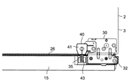
図5は冷蔵室5の断熱扉14、15のロック機構40の側面断面図を示している。ロック機構40は保持部材30上に配される樹脂成形品から成る中空の筐体41を有している。筐体41は前面に開口部41aを開口し、内部の底面41bが筐体41の前部に下端を有した円錐面に形成される。筐体41には前部を開口部41aから突出して前後に延びるレバー部材43が水平な回動軸を形成する軸部43aで軸支される。これにより、レバー部材43は鉛直面内で回動可能になっている。レバー部材43の前端には下方に屈曲した鉤状の突出部43bが設けられる。   FIG. 5 shows a side sectional view of the lock mechanism 40 of the heat insulating doors 14 and 15 of the refrigerator compartment 5. The lock mechanism 40 has a hollow housing 41 made of a resin molded product disposed on the holding member 30. The housing 41 has an opening 41 a on the front surface, and an inner bottom surface 41 b is formed in a conical surface having a lower end at the front of the housing 41. A lever member 43 that protrudes from the opening 41a and extends in the front-rear direction to the housing 41 is pivotally supported by a shaft portion 43a that forms a horizontal rotation shaft. Thereby, the lever member 43 can be rotated in the vertical plane. At the front end of the lever member 43, a hook-like protrusion 43b bent downward is provided.

筐体41内の底面41b上には金属等の球体42が配される。球体42は平常時には円錐面の底面41bの下端に配置される。この時、レバー部材43は自重によって後部が下がるように配置される。   A sphere 42 made of metal or the like is disposed on the bottom surface 41 b in the housing 41. The sphere 42 is normally disposed at the lower end of the bottom surface 41b of the conical surface. At this time, the lever member 43 is disposed so that the rear part is lowered by its own weight.

ロック機構40が振動すると球体42が筐体41の底面41b上を転動し、一点鎖線42’で示すように軸部43aから離れる方向に移動して筐体41の後部に配される。これにより、レバー部材43は一点鎖線43’で示すように球体42により後部が持ち上げられ、前端が降下する。振動が終了すると球体42は重力により底面41bの下端に配置され、レバー部材43の自重によりレバー部材43の前端が上昇する。   When the lock mechanism 40 vibrates, the sphere 42 rolls on the bottom surface 41 b of the housing 41, moves in a direction away from the shaft portion 43 a as shown by a one-dot chain line 42 ′, and is arranged at the rear portion of the housing 41. As a result, the lever member 43 is lifted at the rear by the sphere 42 as indicated by the alternate long and short dash line 43 ', and the front end is lowered. When the vibration is finished, the spherical body 42 is arranged at the lower end of the bottom surface 41 b by gravity, and the front end of the lever member 43 is raised by the weight of the lever member 43.

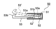
図6は断熱扉16〜19のロック機構50の側面断面図を示している。ロック機構50は仕切壁12等の上面に配される樹脂成形品から成る中空の筐体51を有している。筐体51は前面に開口部51aを開口し、内部の底面51bが筐体51の後部に下端を有した円錐面に形成される。筐体51には前部を開口部51aから突出して前後に延びるレバー部材53が水平な回動軸を形成する軸部53aで軸支される。これにより、レバー部材53は鉛直面内で回動可能になっている。レバー部材53の前端には上方に屈曲した鉤状の突出部53bが設けられる。   FIG. 6 is a side sectional view of the lock mechanism 50 of the heat insulating doors 16 to 19. The lock mechanism 50 has a hollow casing 51 made of a resin molded product disposed on the upper surface of the partition wall 12 and the like. The housing 51 has an opening 51 a on the front surface, and an inner bottom surface 51 b is formed in a conical surface having a lower end at the rear of the housing 51. A lever member 53 that protrudes forward from the opening 51a and extends forward and backward is pivotally supported on the housing 51 by a shaft portion 53a that forms a horizontal rotation shaft. Thereby, the lever member 53 can be rotated in a vertical plane. At the front end of the lever member 53, a hook-like protrusion 53b bent upward is provided.

筐体51内の底面51b上には金属等の球体52が配される。球体52は平常時には円錐面の底面51bの下端に配置される。この時、レバー部材53は自重によって前部が下がるように配置される。   A sphere 52 made of metal or the like is disposed on the bottom surface 51 b in the housing 51. The sphere 52 is normally disposed at the lower end of the conical bottom surface 51b. At this time, the lever member 53 is arranged so that the front part is lowered by its own weight.

ロック機構50が振動すると球体52が筐体51の底面51b上を転動し、一点鎖線52’で示すように軸部53aから離れる方向に移動して筐体51の前部に配される。これにより、レバー部材53は一点鎖線53’で示すように球体52により前端が持ち上げられる。振動が終了すると球体52は重力により底面51bの下端に配置され、レバー部材53の自重によりレバー部材53の前端が降下する。   When the lock mechanism 50 vibrates, the sphere 52 rolls on the bottom surface 51 b of the housing 51, moves in a direction away from the shaft portion 53 a as shown by a one-dot chain line 52 ′, and is arranged at the front portion of the housing 51. As a result, the front end of the lever member 53 is lifted by the sphere 52 as indicated by the alternate long and short dash line 53 '. When the vibration is finished, the sphere 52 is arranged at the lower end of the bottom surface 51 b by gravity, and the front end of the lever member 53 is lowered by the weight of the lever member 53.

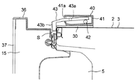
図7、図8は冷蔵庫1の上部の右側面断面図であり、ロック機構40を通る断面を示している。平常時には図7に示すように、ロック機構40のレバー部材43の前端に設けた突出部43bは係合部35よりも上方に配置される。これにより、断熱扉14、15を開閉することができる。   7 and 8 are right side cross-sectional views of the upper portion of the refrigerator 1, and show a cross section passing through the lock mechanism 40. As shown in FIG. 7, the protrusion 43 b provided at the front end of the lever member 43 of the lock mechanism 40 is disposed above the engagement portion 35 in a normal state. Thereby, the heat insulation doors 14 and 15 can be opened and closed.

地震が発生すると本体部2の振動がロック機構40に伝達されてロック機構40が振動し、レバー部材43の前端が降下する。これにより、図8に示すように断熱扉14、15は開き始めても突出部43bと係合部35との係合により閉止状態がロックされ、断熱扉14、15の開放が阻止される。   When an earthquake occurs, the vibration of the main body 2 is transmitted to the lock mechanism 40, the lock mechanism 40 vibrates, and the front end of the lever member 43 is lowered. As a result, as shown in FIG. 8, even if the heat insulating doors 14 and 15 start to open, the closed state is locked by the engagement between the protruding portion 43 b and the engaging portion 35, and the heat insulating doors 14 and 15 are prevented from being opened.

また、ロック機構50もロック機構40と同様に動作する。即ち、断熱扉16〜19の背面には係合部35と同様の左右方向に延びるバー状の係合部(不図示)がロック機構50に対向して設けられる。平常時にはロック機構50のレバー部材53の前端に設けた突出部53bは係合部よりも下方に配置される。これにより、断熱扉16〜19を開閉することができる。   Further, the lock mechanism 50 operates in the same manner as the lock mechanism 40. That is, a bar-shaped engaging portion (not shown) extending in the left-right direction similar to the engaging portion 35 is provided on the back surfaces of the heat insulating doors 16 to 19 so as to face the lock mechanism 50. In normal times, the protruding portion 53b provided at the front end of the lever member 53 of the lock mechanism 50 is disposed below the engaging portion. Thereby, the heat insulation doors 16-19 can be opened and closed.

地震が発生すると本体部2の振動がロック機構50に伝達されてロック機構50が振動し、レバー部材53の前端が上昇する。これにより、断熱扉16〜19は開き始めても突出部53bと係合部との係合により閉止状態がロックされ、断熱扉16〜19の開放が阻止される。   When an earthquake occurs, the vibration of the main body 2 is transmitted to the lock mechanism 50, the lock mechanism 50 vibrates, and the front end of the lever member 53 rises. Thereby, even if it begins to open the heat insulation doors 16-19, a closed state is locked by engagement with the protrusion part 53b and an engagement part, and opening | release of the heat insulation doors 16-19 is blocked | prevented.

従って、開放された断熱扉14〜19や、断熱扉14、15の開放により落下した貯蔵物と、使用者との衝突を防止することができる。この時、断熱扉14、15のロック機構40は枢支軸Cを形成するヒンジピン32の近傍に配置される。このため、経年使用によって断熱扉14、15の開放端が降下しても、突出部43bを係合部35に係合させることができる。これにより、断熱扉14、15の開放を確実に阻止することができる。   Therefore, it is possible to prevent the user from colliding with the opened heat-insulating doors 14 to 19 and the stored items dropped by opening the heat-insulating doors 14 and 15. At this time, the lock mechanism 40 of the heat insulating doors 14 and 15 is disposed in the vicinity of the hinge pin 32 that forms the pivot shaft C. For this reason, even if the open ends of the heat insulating doors 14 and 15 are lowered due to use over time, the protruding portion 43 b can be engaged with the engaging portion 35. Thereby, opening of the heat insulation doors 14 and 15 can be prevented reliably.

特に、断熱扉14、15がガラス板37を有するため重量が大きく、経年使用による開放端の降下量が大きい。しかしながら、ロック機構40を枢支軸Cの近傍に配置することにより、断熱扉14、15の開放を確実に阻止することができる。   In particular, since the heat insulating doors 14 and 15 have the glass plate 37, the weight is large, and the amount of lowering of the open end due to aging is large. However, by disposing the lock mechanism 40 in the vicinity of the pivot shaft C, it is possible to reliably prevent the heat insulating doors 14 and 15 from being opened.

また、断熱扉16〜19のロック機構50は貯氷ケースや収納ケース17a〜19aにより上方を覆われる。これにより、冷蔵庫1の美観を向上することができる。   The lock mechanism 50 of the heat insulating doors 16 to 19 is covered with an ice storage case and storage cases 17a to 19a. Thereby, the beauty | look of the refrigerator 1 can be improved.

本実施形態によると、鉛直面内で回動可能なレバー部材43の前端が降下して断熱扉14、15の閉止状態をロックするロック機構40を断熱扉14、15の枢支軸Cの近傍に配置している。このため、経年使用によって断熱扉14、15の開放端が降下しても突出部43bを係合部35に係合させることができる。従って、断熱扉14、15の開放を確実に阻止し、冷蔵庫1の安全性を向上することができる。   According to this embodiment, the lock mechanism 40 that locks the closed state of the heat-insulating doors 14 and 15 by lowering the front end of the lever member 43 that can rotate in the vertical plane is located near the pivot shaft C of the heat-insulating doors 14 and 15. Is arranged. For this reason, even if the open ends of the heat insulating doors 14 and 15 are lowered due to aging, the protruding portion 43b can be engaged with the engaging portion 35. Therefore, it is possible to reliably prevent the heat insulating doors 14 and 15 from being opened and improve the safety of the refrigerator 1.

また、左右方向に延びてレバー部材43の前端の突出部43bに係合する係合部35を断熱扉14、15の上端部に設けたので、突出部43bと係合部35との係合によって容易に断熱扉14、15の開放を阻止することができる。   Moreover, since the engaging part 35 extended in the left-right direction and engaged with the protrusion part 43b of the front end of the lever member 43 was provided in the upper end part of the heat insulation doors 14 and 15, engagement with the protrusion part 43b and the engagement part 35 is provided. Can easily prevent the heat insulating doors 14 and 15 from being opened.

また、ヒンジピン32を保持する保持部材30にロック機構40を取り付けたので、枢支軸Cの近傍にロック機構40を容易に配置することができる。   In addition, since the lock mechanism 40 is attached to the holding member 30 that holds the hinge pin 32, the lock mechanism 40 can be easily disposed in the vicinity of the pivot shaft C.

本実施形態において、ロック機構40に替えて断熱扉16〜19のロック機構50を保持部材31上に設け、係合部35を断熱扉14、15の下端部に設けてもよい。また、レバー部材43、53の突出部43b、53bを左右に延びるバー状に形成し、係合部(35等)を鉤状に形成してもよい。   In the present embodiment, the lock mechanism 50 of the heat insulating doors 16 to 19 may be provided on the holding member 31 in place of the lock mechanism 40, and the engaging portion 35 may be provided at the lower ends of the heat insulating doors 14 and 15. Alternatively, the protrusions 43b and 53b of the lever members 43 and 53 may be formed in a bar shape extending left and right, and the engaging portion (35 etc.) may be formed in a hook shape.

<第2実施形態>
次に、図9は第2実施形態の冷蔵庫1の正面図を示している。説明の便宜上、前述の図1〜図8に示す第1実施形態と同様の部分には同一の符号を付している。本実施形態は断熱扉14のロック機構40の配置が第1実施形態と異なっている。その他の部分は第1実施形態と同様である。
Second Embodiment
Next, FIG. 9 has shown the front view of the refrigerator 1 of 2nd Embodiment. For convenience of explanation, the same reference numerals are given to the same parts as those in the first embodiment shown in FIGS. In the present embodiment, the arrangement of the lock mechanism 40 of the heat insulating door 14 is different from that of the first embodiment. Other parts are the same as those in the first embodiment.

断熱扉15のロック機構40は第1実施形態と同様に、枢支軸Cの近傍に配置されるため、経年使用により開放端が降下しても確実に断熱扉15をロックすることができる。   Since the lock mechanism 40 of the heat insulating door 15 is disposed in the vicinity of the pivot shaft C as in the first embodiment, the heat insulating door 15 can be reliably locked even if the open end is lowered due to aging.

断熱扉14のロック機構40は本体部2の天井面に取り付けられ、断熱扉14の開放側の端部に配置される。断熱扉15よりも横幅の狭い断熱扉14は自重による変形やヒンジピン32(図6参照)の摩耗による傾斜が発生しにくいため、経年使用による開放端の降下が少ない。このため、ロック機構40を断熱扉14の開放側の端部に配置しても、地震発生時に断熱扉14を確実にロックすることができる。   The lock mechanism 40 of the heat insulating door 14 is attached to the ceiling surface of the main body 2 and is disposed at the end of the heat insulating door 14 on the open side. Since the heat insulation door 14 having a narrower width than the heat insulation door 15 is less likely to be deformed by its own weight or inclined due to wear of the hinge pin 32 (see FIG. 6), the fall of the open end due to use over time is small. For this reason, even if it arrange | positions the locking mechanism 40 in the edge part of the open side of the heat insulation door 14, the heat insulation door 14 can be reliably locked at the time of the occurrence of an earthquake.

この時、断熱扉14のロック機構40は枢支軸Cから離れるため、開放される断熱扉14から受ける力が小さい。従って、断熱扉14のロック機構40を小型化して冷蔵庫1のコストを削減することができる。   At this time, since the locking mechanism 40 of the heat insulating door 14 is separated from the pivot shaft C, the force received from the heat insulating door 14 to be opened is small. Therefore, the lock mechanism 40 of the heat insulating door 14 can be downsized to reduce the cost of the refrigerator 1.

<第3実施形態>
次に、図10は第3実施形態の冷蔵庫1の右部の上面図を示している。説明の便宜上、前述の図1〜図8に示す第1実施形態と同様の部分には同一の符号を付している。本実施形態は断熱扉14、15のロック機構40の配置及びレバー部材43の形状が第1実施形態と異なっている。その他の部分は第1実施形態と同様である。
<Third Embodiment>
Next, FIG. 10 has shown the top view of the right part of the refrigerator 1 of 3rd Embodiment. For convenience of explanation, the same reference numerals are given to the same parts as those in the first embodiment shown in FIGS. In the present embodiment, the arrangement of the lock mechanism 40 of the heat insulating doors 14 and 15 and the shape of the lever member 43 are different from those of the first embodiment. Other parts are the same as those in the first embodiment.

断熱扉15のロック機構40は保持部材30に取り付けられ、ヒンジピン32により形成される枢支軸C(図1参照)よりも外側に配置される。断熱扉14(図1参照)のロック機構40も同様に、保持部材30に取り付けられ、枢支軸Cよりも外側に配置される。   The lock mechanism 40 of the heat insulating door 15 is attached to the holding member 30 and is arranged outside the pivot shaft C (see FIG. 1) formed by the hinge pins 32. Similarly, the lock mechanism 40 of the heat insulating door 14 (see FIG. 1) is attached to the holding member 30 and arranged outside the pivot shaft C.

図11は冷蔵庫1の上部のロック機構40を通る右側面断面図を示している。断熱扉14、15と断熱箱体3の前面との間にはパッキン26によって隙間Sが形成される。ロック機構40のレバー部材43の前端に設けられる突出部43bは平板状に形成され、隙間Sに進入可能な前後方向の幅を有する。   FIG. 11 shows a right side cross-sectional view through the lock mechanism 40 at the top of the refrigerator 1. A gap S is formed by the packing 26 between the heat insulating doors 14 and 15 and the front surface of the heat insulating box 3. The protrusion 43 b provided at the front end of the lever member 43 of the lock mechanism 40 is formed in a flat plate shape and has a width in the front-rear direction that can enter the gap S.

平常時には同図に示すように、ロック機構40のレバー部材43の前端に設けた突出部43bは断熱扉14、15の上面よりも上方に配置される。これにより、断熱扉14、15を開閉することができる。   As shown in the figure, the protrusion 43b provided at the front end of the lever member 43 of the lock mechanism 40 is disposed above the upper surfaces of the heat insulating doors 14 and 15 in a normal state. Thereby, the heat insulation doors 14 and 15 can be opened and closed.

地震が発生すると本体部2の振動がロック機構40に伝達されてロック機構40が振動し、図12に示すようにレバー部材43の前端が降下する。これにより、突出部43bが枢支軸Cよりも外側の隙間Sに進入し、断熱扉14、15の閉止状態がロックされて断熱扉14、15の開放が阻止される。従って、第1実施形態と同様の効果を得ることができ
る。
When an earthquake occurs, the vibration of the main body 2 is transmitted to the lock mechanism 40 and the lock mechanism 40 vibrates, and the front end of the lever member 43 is lowered as shown in FIG. Thereby, the protrusion 43b enters the gap S outside the pivot shaft C, the closed state of the heat insulating doors 14 and 15 is locked, and the heat insulating doors 14 and 15 are prevented from being opened. Therefore, the same effect as the first embodiment can be obtained.

尚、前述の図6に示すロック機構50を本実施形態の突出部43bと同様に突出部53bを形成し、ロック機構40に替えて断熱扉14、15の下方の保持部材31(図1参照)に取り付けてもよい。   The locking mechanism 50 shown in FIG. 6 is formed with a protruding portion 53b in the same manner as the protruding portion 43b of the present embodiment, and the holding member 31 below the heat insulating doors 14 and 15 is replaced with the locking mechanism 40 (see FIG. 1). ).

また、第1〜第3実施形態において、断熱扉14、15にヒンジピン32の保持部材30、31を設け、本体部2に軸受部33を設けてもよい。この時、ロック機構40を軸受部33に取り付けることにより、枢支軸Cの近傍にロック機構40を配置することができる。   In the first to third embodiments, the heat insulating doors 14 and 15 may be provided with the holding members 30 and 31 of the hinge pin 32, and the main body 2 may be provided with the bearing portion 33. At this time, the lock mechanism 40 can be disposed in the vicinity of the pivot shaft C by attaching the lock mechanism 40 to the bearing portion 33.

<第4実施形態>
次に、図13は第4実施形態の冷蔵庫1の正面図を示している。説明の便宜上、前述の図1〜図8に示す第1実施形態と同様の部分には同一の符号を付している。本実施形態は冷蔵室5の断熱扉14(図1参照)を省いて断熱扉15が片開きに形成される。また、断熱扉15のロック機構40に替えてロック機構60が設けられる。その他の部分は第1実施形態と同様である。
<Fourth embodiment>
Next, FIG. 13 has shown the front view of the refrigerator 1 of 4th Embodiment. For convenience of explanation, the same reference numerals are given to the same parts as those in the first embodiment shown in FIGS. In the present embodiment, the heat insulation door 15 is formed in a single opening without the heat insulation door 14 (see FIG. 1) of the refrigerator compartment 5. Further, a lock mechanism 60 is provided instead of the lock mechanism 40 of the heat insulating door 15. Other parts are the same as those in the first embodiment.

冷蔵庫1は本体部2の上方から順に冷蔵室5、冷凍室8、野菜室9が設けられ、それぞれ断熱扉15、18、19により開閉される。断熱扉15は本体部2の右端部に設けた保持部材30、31に保持されるヒンジピン32によって枢支軸Cが形成される。   The refrigerator 1 is provided with a refrigerator compartment 5, a freezer compartment 8, and a vegetable compartment 9 in order from the top of the main body 2, and is opened and closed by heat insulating doors 15, 18 and 19, respectively. The heat insulating door 15 has a pivot shaft C formed by hinge pins 32 held by holding members 30 and 31 provided at the right end of the main body 2.

ロック機構60は断熱扉15の開放端である冷蔵室5の左側壁の上部に取り付けられる。断熱扉15の左側面には上下方向に延びたバー状の係合部35(図14、図15参照)が設けられる。   The lock mechanism 60 is attached to the upper part of the left side wall of the refrigerator compartment 5, which is the open end of the heat insulating door 15. A bar-shaped engaging portion 35 (see FIGS. 14 and 15) extending in the vertical direction is provided on the left side surface of the heat insulating door 15.

図14、図15はロック機構60の上面断面図及び側面断面図を示している。ロック機構60は冷蔵室5の側壁に配される樹脂成形品から成る中空の筐体61を有している。筐体61は前面に開口部61aを開口し、内部の底面61bが筐体61の前部に下端を有した円錐面に形成される。また、筐体61の内部の右側面61cは後方が左方向に傾斜した傾斜面に形成される。   14 and 15 show a top sectional view and a side sectional view of the lock mechanism 60. The lock mechanism 60 has a hollow casing 61 made of a resin molded product disposed on the side wall of the refrigerator compartment 5. The housing 61 has an opening 61 a at the front surface, and an inner bottom surface 61 b is formed in a conical surface having a lower end at the front of the housing 61. Further, the right side surface 61c inside the housing 61 is formed as an inclined surface whose rear side is inclined leftward.

筐体61には前部を開口部61aから突出して前後に延びるレバー部材63が鉛直な回動軸を形成する軸部63aで軸支される。これにより、レバー部材63は水平面内で回動可能になっている。レバー部材63の前端には右方に屈曲した鉤状の突出部63bが設けられる。   A lever member 63 that projects from the opening 61a and extends in the front-rear direction to the housing 61 is pivotally supported by a shaft portion 63a that forms a vertical rotation shaft. Thereby, the lever member 63 is rotatable in a horizontal plane. At the front end of the lever member 63, a hook-shaped protrusion 63b bent rightward is provided.

筐体61内の底面61b上には金属等の球体62が配される。球体62は平常時には円錐面の底面61bの下端に配置される。この時、レバー部材53は弾性部材(不図示)の付勢によって突出部63bが係合部35よりも左方に配置される。これにより、断熱扉15を開閉することができる。   A sphere 62 made of metal or the like is disposed on the bottom surface 61 b in the housing 61. The sphere 62 is normally disposed at the lower end of the bottom surface 61b of the conical surface. At this time, the protruding portion 63b of the lever member 53 is arranged on the left side of the engaging portion 35 by the biasing of an elastic member (not shown). Thereby, the heat insulation door 15 can be opened and closed.

地震の発生により本体部2の振動がロック機構60に伝達されてロック機構60が振動すると、筐体61の底面61b上を球体62が転動する。これにより、球体62が一点鎖線62’で示すように軸部63aから離れる方向に移動して筐体61の後部に配される。この時、球体62は右側面61cに沿って左方向に移動し、レバー部材63が一点鎖線63’で示すように前端を右方に回動し、突出部63bが係合部35に係合する。これにより、断熱扉15は開き始めても突出部63bと係合部35との係合により閉止状態がロックされ、断熱扉15の開放が阻止される。   When the vibration of the main body 2 is transmitted to the lock mechanism 60 due to the occurrence of an earthquake and the lock mechanism 60 vibrates, the sphere 62 rolls on the bottom surface 61 b of the housing 61. As a result, the sphere 62 moves in the direction away from the shaft portion 63a as shown by the alternate long and short dash line 62 'and is arranged at the rear portion of the housing 61. At this time, the sphere 62 moves to the left along the right side surface 61c, the lever member 63 rotates to the right as shown by the alternate long and short dash line 63 ', and the protruding portion 63b engages with the engaging portion 35. To do. Thereby, even if the heat insulation door 15 begins to open, a closed state is locked by engagement with the protrusion part 63b and the engaging part 35, and opening | release of the heat insulation door 15 is blocked | prevented.

振動が終了すると球体62は重力により底面61bの下端に配置され、レバー部材63の前端が弾性部材により左方に移動する。   When the vibration is finished, the sphere 62 is arranged at the lower end of the bottom surface 61b by gravity, and the front end of the lever member 63 is moved to the left by the elastic member.

本実施形態によると、水平面内で回動可能なレバー部材63の前端が左右方向に移動して断熱扉15の閉止状態をロックするロック機構60を設けている。このため、経年使用によって断熱扉15の開放端が降下しても突出部63bが係合部35に係合して断熱扉15をロックすることができる。従って、断熱扉15の開放を確実に阻止し、冷蔵庫1の安全性を向上することができる。   According to this embodiment, the lock mechanism 60 that locks the closed state of the heat insulating door 15 by moving the front end of the lever member 63 that can be rotated in a horizontal plane in the left-right direction is provided. For this reason, even if the open end of the heat insulation door 15 descends due to use over time, the protrusion 63b can engage with the engagement portion 35 and the heat insulation door 15 can be locked. Accordingly, it is possible to reliably prevent the heat insulating door 15 from being opened and to improve the safety of the refrigerator 1.

また、上下方向に延びてレバー部材63の前端の突出部63bに係合する係合部35を断熱扉15の側面に設けたので、突出部63bと係合部35との係合によって容易に断熱扉15の開放を阻止することができる。   Further, since the engaging portion 35 that extends in the vertical direction and engages with the protruding portion 63b at the front end of the lever member 63 is provided on the side surface of the heat insulating door 15, it is easy to engage with the protruding portion 63b and the engaging portion 35. Opening of the heat insulating door 15 can be prevented.

本実施形態において、突出部63bを前述の図11に示す第3実施形態の突出部43bと同様に形成し、ロック機構60を断熱扉15の枢支側である冷蔵室5の右側壁に取り付けてもよい。また、レバー部材63の突出部63bをバー状に形成して係合部35を鉤状に形成してもよい。   In this embodiment, the protrusion 63b is formed in the same manner as the protrusion 43b of the third embodiment shown in FIG. 11 described above, and the lock mechanism 60 is attached to the right side wall of the refrigerator compartment 5 which is the pivot side of the heat insulating door 15. May be. Further, the protruding portion 63b of the lever member 63 may be formed in a bar shape, and the engaging portion 35 may be formed in a hook shape.

また、第1〜第4実施形態において、ロック機構40、50、60のレバー部材43、53、63が球体42、52、62の転動により回動するが、筐体41、51、61に一端を支持した錘の揺動により回動してもよい。   In the first to fourth embodiments, the lever members 43, 53, 63 of the lock mechanisms 40, 50, 60 are rotated by the rolling of the spheres 42, 52, 62. You may rotate by rocking | fluctuating the weight which supported one end.

また、第1〜第4実施形態において、ロック機構40、50、60を本体部2に替えて断熱扉14〜19の上下の端部や側面に設け、振動発生時にレバー部材43、53、63が本体部2に係合してもよい。   In the first to fourth embodiments, the lock mechanisms 40, 50, 60 are provided on the upper and lower ends and side surfaces of the heat insulating doors 14-19 in place of the main body 2, and the lever members 43, 53, 63 are provided when vibration is generated. May engage the main body 2.

本発明は、地震発生時に扉をロックするロック機構を備えた冷蔵庫に利用することができる。   INDUSTRIAL APPLICATION This invention can be utilized for the refrigerator provided with the locking mechanism which locks a door at the time of the occurrence of an earthquake.

1 冷蔵庫
2 本体部
3 断熱箱体
4、10 断熱材
5 冷蔵室
6 製氷室
7、8 冷凍室
9 野菜室
11、12 仕切壁
13 仕切部
14〜19 断熱扉
15a ドアポケット
17a〜19a 収納ケース
20 機械室
21 圧縮機
22 冷却器
23 送風機
24、25 冷気通路
26 パッキン
30、31 保持部材
32 ヒンジピン
33 軸受部
35 係合部
36 上面カバー
40、50、60 ロック機構
41、51、61 筐体
42、52、62 球体
43、53、63 レバー部材
43b、53b、63b 突出部
DESCRIPTION OF SYMBOLS 1 Refrigerator 2 Main body part 3 Heat insulation box 4, 10 Heat insulation material 5 Refrigeration room 6 Ice making room 7, 8 Freezing room 9 Vegetable room 11, 12 Partition wall 13 Partition part 14-19 Heat insulation door 15a Door pocket 17a-19a Storage case 20 Machine room 21 Compressor 22 Cooler 23 Blower 24, 25 Cooling air passage 26 Packing 30, 31 Holding member 32 Hinge pin 33 Bearing portion 35 Engaging portion 36 Top cover 40, 50, 60 Lock mechanism 41, 51, 61 Housing 42, 52, 62 Sphere 43, 53, 63 Lever member 43b, 53b, 63b Projection

Claims (4)

前面を開口した貯蔵室を有する本体部と、鉛直な枢支軸で前記本体部に枢支されて前記貯蔵室の前面を開閉する断熱扉と、鉛直面内で回動可能なレバー部材を有するロック機構とを備え、前記ロック機構が振動したときに前記レバー部材の前端が上下動して前記断熱扉の閉止状態をロックするとともに、振動停止時に前記レバー部材の前端が前記断熱扉をロックする位置から退避して前記断熱扉の閉止状態のロックを解除する冷蔵庫において、前記枢支軸を形成するヒンジピンを保持した保持部材が前記本体部に固定されるとともに前記ロック機構が前記保持部材上に位置決めされて取り付けられ、前記ヒンジピンを軸支して前記枢支軸を形成する軸受部及び前記レバー部材に対向する係合部が前記断熱扉の上端部または下端部に一体に形成されて、前記ロック機構が非振動の状態では前記レバー部材が前記係合部に接触せず、前記ロック機構が振動したときは前記レバー部材が前記係合部に係合することを特徴とする冷蔵庫。 A main body having a storage chamber having an open front surface, a heat insulating door that is pivotally supported by the main body by a vertical pivot shaft to open and close the front surface of the storage chamber, and a lever member that is rotatable in a vertical plane. A locking mechanism, and when the locking mechanism vibrates, the front end of the lever member moves up and down to lock the closed state of the heat insulating door, and when the vibration stops, the front end of the lever member locks the heat insulating door. In a refrigerator that retreats from a position and releases the lock of the closed state of the heat insulating door, a holding member holding a hinge pin that forms the pivot shaft is fixed to the main body portion, and the locking mechanism is placed on the holding member A bearing portion that is positioned and mounted and pivotally supports the hinge pin to form the pivot shaft and an engaging portion that opposes the lever member are integrally formed at the upper end portion or the lower end portion of the heat insulating door. Is in the locking mechanism the lever member is not in contact with the engaging portion in the non-oscillating state, when the locking mechanism is vibrated is characterized in that said lever member is engaged with the engaging portion refrigerator. 前記ロック機構が前記枢支軸の近傍となるように、前記枢支軸と前記断熱扉の開放側の端部との中間位置よりも前記枢支軸側に前記ロック機構を配置したことを特徴とする請求項1に記載の冷蔵庫。 The lock mechanism is disposed closer to the pivot shaft than an intermediate position between the pivot shaft and the open end of the heat insulating door so that the lock mechanism is in the vicinity of the pivot shaft. The refrigerator according to claim 1. 前記断熱扉の前面にガラス板を配したことを特徴とする請求項2に記載の冷蔵庫。 The refrigerator according to Motomeko 2 characterized in that arranged glass plate in front of the insulating door. 前記断熱扉の背面にドアポケットを配したことを特徴とする請求項2または請求項3に記載の冷蔵庫。 The refrigerator according to claim 2 or 3 , wherein a door pocket is arranged on a back surface of the heat insulating door.
JP2015226284A 2015-11-19 2015-11-19 refrigerator Active JP6219908B2 (en)

Priority Applications (1)

Application Number Priority Date Filing Date Title
JP2015226284A JP6219908B2 (en) 2015-11-19 2015-11-19 refrigerator

Applications Claiming Priority (1)

Application Number Priority Date Filing Date Title
JP2015226284A JP6219908B2 (en) 2015-11-19 2015-11-19 refrigerator

Related Parent Applications (1)

Application Number Title Priority Date Filing Date
JP2013175398A Division JP5844782B2 (en) 2013-08-27 2013-08-27 refrigerator

Related Child Applications (1)

Application Number Title Priority Date Filing Date
JP2017186510A Division JP6475803B2 (en) 2017-09-27 2017-09-27 refrigerator

Publications (3)

Publication Number Publication Date
JP2016042021A JP2016042021A (en) 2016-03-31
JP2016042021A5 JP2016042021A5 (en) 2016-10-13
JP6219908B2 true JP6219908B2 (en) 2017-10-25

Family

ID=55591841

Family Applications (1)

Application Number Title Priority Date Filing Date
JP2015226284A Active JP6219908B2 (en) 2015-11-19 2015-11-19 refrigerator

Country Status (1)

Country Link
JP (1) JP6219908B2 (en)

Family Cites Families (12)

* Cited by examiner, † Cited by third party
Publication number Priority date Publication date Assignee Title
US5522656A (en) * 1995-03-21 1996-06-04 General Electric Company Refrigerator door closure system
JPH0933162A (en) * 1995-07-21 1997-02-07 Sanyo Electric Co Ltd Storehouse
JPH0996157A (en) * 1995-07-22 1997-04-08 Hiroko Hashizume Locking device during earthquake
JP3752588B2 (en) * 1995-09-27 2006-03-08 橋爪 英彌 Locking the hinged door during an earthquake
JPH10266674A (en) * 1997-03-21 1998-10-06 Nifco Inc Vibration lock device for door
JP3401477B2 (en) * 2000-06-09 2003-04-28 磯川産業株式会社 Seismic door safety device
JP2006177624A (en) * 2004-12-22 2006-07-06 Toshiba Corp Refrigerator
JP2006169958A (en) * 2006-02-06 2006-06-29 Nifco Inc Earthquake resistant lock device
DE202007001638U1 (en) * 2007-02-05 2007-04-05 Dometic Gmbh Portable refrigerator to be fastened with a hook-bolt lock has a refrigerator door kept magnetically closed against a carcass and a hook-bolt lock
KR20080079113A (en) * 2007-02-26 2008-08-29 삼성전자주식회사 Refrigerator
EP2717004B1 (en) * 2011-05-23 2018-09-12 Hefei Midea Refrigerator Co., Ltd. Door closure structure for rotary cabinet door and side by side refrigerator with the door closure structure
JP2013061134A (en) * 2011-09-14 2013-04-04 Sharp Corp Refrigerator

Also Published As

Publication number Publication date
JP2016042021A (en) 2016-03-31

Similar Documents

Publication Publication Date Title
KR102606132B1 (en) Refrigerator
EP3190367B1 (en) Refrigerator
EP3190368B1 (en) Refrigerator
US20180038631A1 (en) Refrigerator
KR20180062122A (en) Refrigerator
KR20100037764A (en) Refrigerator
JP5219935B2 (en) Freezer refrigerator
JP5844782B2 (en) refrigerator
JP6475803B2 (en) refrigerator
JP6219908B2 (en) refrigerator
JP4881649B2 (en) Door support structure
JP6285208B2 (en) refrigerator
JP6374183B2 (en) refrigerator
JPWO2018189808A1 (en) refrigerator
KR20090075017A (en) An ice maker of bottom freezer type refrigerator
JP2021096009A (en) refrigerator
JP2015161483A (en) refrigerator
KR100695539B1 (en) The wine cellar
JP6813262B2 (en) refrigerator
US20200378678A1 (en) Storage structure for an appliance
JP2003050080A (en) Refrigerator
JP2013068389A (en) Refrigerator
JP2020060310A (en) refrigerator
JP2006313039A (en) Refrigerator
KR20100012565A (en) Hinge structure and refrigerator having it

Legal Events

Date Code Title Description
A521 Written amendment

Free format text: JAPANESE INTERMEDIATE CODE: A523

Effective date: 20160824

A621 Written request for application examination

Free format text: JAPANESE INTERMEDIATE CODE: A621

Effective date: 20160824

RD02 Notification of acceptance of power of attorney

Free format text: JAPANESE INTERMEDIATE CODE: A7422

Effective date: 20161104

A977 Report on retrieval

Free format text: JAPANESE INTERMEDIATE CODE: A971007

Effective date: 20170419

A131 Notification of reasons for refusal

Free format text: JAPANESE INTERMEDIATE CODE: A131

Effective date: 20170425

A521 Written amendment

Free format text: JAPANESE INTERMEDIATE CODE: A523

Effective date: 20170621

TRDD Decision of grant or rejection written
A01 Written decision to grant a patent or to grant a registration (utility model)

Free format text: JAPANESE INTERMEDIATE CODE: A01

Effective date: 20170829

A61 First payment of annual fees (during grant procedure)

Free format text: JAPANESE INTERMEDIATE CODE: A61

Effective date: 20170928

R150 Certificate of patent or registration of utility model

Ref document number: 6219908

Country of ref document: JP

Free format text: JAPANESE INTERMEDIATE CODE: R150