JP6219138B2 - Air conditioning operation control system and method - Google Patents
Air conditioning operation control system and method Download PDFInfo
- Publication number
- JP6219138B2 JP6219138B2 JP2013237360A JP2013237360A JP6219138B2 JP 6219138 B2 JP6219138 B2 JP 6219138B2 JP 2013237360 A JP2013237360 A JP 2013237360A JP 2013237360 A JP2013237360 A JP 2013237360A JP 6219138 B2 JP6219138 B2 JP 6219138B2
- Authority
- JP
- Japan
- Prior art keywords
- load
- air
- air conditioning
- time
- upper limit
- Prior art date
- Legal status (The legal status is an assumption and is not a legal conclusion. Google has not performed a legal analysis and makes no representation as to the accuracy of the status listed.)
- Active
Links
Images


Description
本発明は、熱供給プラントからビル等の熱需要家に向けて温冷熱を供給する冷暖房システムにおいて、需要家側の空調機の運転を制御する空調運転制御システム及びその方法に関するものである。 The present invention relates to an air conditioning operation control system and method for controlling operation of an air conditioner on a customer side in an air conditioning system for supplying hot and cold heat from a heat supply plant to a heat consumer such as a building.
特許文献1には、蓄熱を過不足なく利用しつつも、蓄熱の不足、あるいは圧縮機の発停の頻回を回避する空気調和機の制御方法を提供することを目的として「ある時刻迄に消費された蓄熱量を満蓄時の蓄熱量から差し引いて、その時刻の蓄熱の残留量を求め、この残留量が、この時刻以後、蓄熱利用完了予定時刻までに消費が見込まれる空調負荷を賄えるのであれば、蓄熱のみで空気調和動作を行う。これにより、蓄熱量が十分大きな場合に、ピークカット厳守時間帯よりも早くから、蓄熱のみによって空気調和動作を行うことで、蓄熱設備での蓄熱量を無駄にすることなく、圧縮機が停止される期間も稼ぎつつ消費電力を低減する」ことが記載されている。
冷暖房においては、オフィスビル等の需要家が自身の消費エネルギー量やCO2排出量の最小化のための最適化を図るようにBEMS(Building Energy Management System)やBAS(Building Automation System)により空調を制御している。そのため、熱を供給する冷暖房センタの熱源設備の運転にとっては非効率となる一時的な需要のピークが朝の空調起動時に発生していた。具体的には、朝のみ一時的に立ち上げる熱源設備(ピーク対応機)を備えることにより、そのピーク対応機を前もって運転準備をしておくことによるエネルギーの無駄と、その負荷が低いために効率の悪い状態で運転することによるエネルギーの無駄がある。 In air conditioning, air conditioning is controlled by BEMS (Building Energy Management System) and BAS (Building Automation System) so that customers such as office buildings can optimize their energy consumption and CO2 emissions. doing. Therefore, a temporary demand peak that becomes inefficient for the operation of the heat source equipment of the air conditioning center that supplies heat occurs at the time of air conditioning startup in the morning. Specifically, by providing a heat source facility (peak response machine) that is temporarily started up only in the morning, energy is wasted by preparing the peak response machine in advance, and the load is low, resulting in efficiency. There is a waste of energy by driving in bad conditions.
特許文献1には蓄熱を過不足なく利用しつつも、蓄熱の不足、あるいは圧縮機の発停の頻回を回避する方法が記されている。しかし、特許文献1に記載された制御方法及びシステムでは、熱負荷のピークを抑制することは可能だが、そのために蓄熱槽を利用することが前提として示されている。
そこで空調運転制御システムでは、空調機の起動時間帯において、空調機を使用する部屋の冷温水需要を満たすことを前提としたうえで、空調機の起動による冷温水需要のピークを、蓄熱槽を用いずに抑制し、かつ冷暖房センタの熱源設備をできるだけ高効率に運転することが課題となる。 Therefore, in the air conditioning operation control system, it is assumed that the cold / hot water demand of the room where the air conditioner is used will be met during the start-up time of the air conditioner. It becomes a problem to control without using and operate the heat source equipment of the air conditioning center as efficiently as possible.
開示する空調運転制御システムの望ましい運転制御装置の態様は、熱源設備と、制御信号に応答して熱源設備からの冷温水を用いて室温を制御する複数台の空調機に接続し、熱源設備が対象とする総熱負荷が、予め指定する上限値を超過するときにその超過を判定する負荷上限超過判定部、複数台の空調機の負荷の再演算を行う熱負荷演算部と、総熱負荷が上限値を超過しない空調スケジュールを決定する空調負荷組合せ部、および、空調スケジュールに基づいた運転を行う様に複数台の空調機に制御信号を出力する空調機制御指令設定部を有する。 A desirable operation control device aspect of the disclosed air conditioning operation control system is connected to a plurality of air conditioners that control room temperature using cold / hot water from a heat source facility and a cold source in response to a control signal. A load upper limit excess determination unit that determines when the target total heat load exceeds a predetermined upper limit value, a heat load calculation unit that recalculates the loads of multiple air conditioners, and a total heat load Has an air conditioning load combination unit that determines an air conditioning schedule that does not exceed the upper limit value, and an air conditioner control command setting unit that outputs a control signal to a plurality of air conditioners so as to perform an operation based on the air conditioning schedule.
開示する空調運転制御システムの運転制御装置及び運転制御方法によれば、朝の空調立上時間帯において、空調機を使用する部屋の冷温水需要を満たしつつ、空調機の起動による冷温水需要のピークを、蓄熱槽を用いずに抑制することが可能となる。 According to the operation control device and the operation control method of the disclosed air conditioning operation control system, in the morning air conditioning start-up time period, while meeting the cold / hot water demand of the room where the air conditioner is used, It becomes possible to suppress the peak without using a heat storage tank.
開示する空調運転制御システムは、熱源設備と、制御信号に応答して、熱源設備からの冷温水を用いて室温を制御する複数台の空調機に接続し、熱源設備が対象とする総熱負荷が、予め指定する上限値を超過するときにその超過を判定する負荷上限超過判定部、複数台の空調機の負荷の再演算を行う熱負荷演算部と、総熱負荷が上限値を超過しない空調スケジュールを決定する空調負荷組合せ部、および、空調スケジュールに基づいた運転を行う様に複数台の空調機に制御信号を出力する空調機制御指令設定部を有する。
なお、上限値としては、熱源設備が最高効率となる値や、熱源設備の最適運転計画を実施した上で熱源設備の一時的な立上げが起きるとされる場合にその閾値となる値を用いる。これにより、高効率な運転が可能となる。
The disclosed air conditioning operation control system is connected to a plurality of air conditioners that control the room temperature using cold / hot water from the heat source equipment in response to the control signal, and the total heat load targeted by the heat source equipment However, when the upper limit value specified in advance is exceeded, the load upper limit excess determination unit that determines the excess, the thermal load calculation unit that recalculates the load of multiple air conditioners, and the total heat load does not exceed the upper limit value An air conditioning load combination unit that determines an air conditioning schedule and an air conditioner control command setting unit that outputs a control signal to a plurality of air conditioners so as to perform an operation based on the air conditioning schedule.
As the upper limit value, a value at which the heat source facility has the highest efficiency, or a threshold value when a temporary start-up of the heat source facility occurs after implementing an optimum operation plan of the heat source facility is used. . Thereby, highly efficient driving | operation becomes possible.
以下、実施例を、図面を用いて説明する。 Hereinafter, examples will be described with reference to the drawings.
本実施例では、空調機起動時間帯において、空調機を必要とする時間帯にその設定温度を変えることによる使用者の便益を損なうことなく、また空調機を起動する部屋による冷温水需要ピークを、蓄熱槽を用いずに抑制し、冷暖房センタの熱源設備をできるだけ高効率に運転する、空調運転制御システム(以下、運転制御装置)101の例を説明する。 In this embodiment, during the air conditioner start-up time period, the cold / hot water demand peak due to the room in which the air conditioner is started is not impaired without impairing the user's benefit by changing the set temperature during the time period when the air conditioner is required. An example of an air conditioning operation control system (hereinafter referred to as an operation control device) 101 that suppresses without using a heat storage tank and operates the heat source equipment of the air conditioning center as efficiently as possible will be described.
図1は、本実施例の冷暖房の運転制御装置101を含む冷暖房システムの構成例である。冷暖房センタ102は熱源機105を保有し、一次配管114にポンプ103により、熱源機105からの冷温水を供給する。冷温水は流量制御弁106と熱交換器107を介して、需要家である建物109へ送られる。熱交換器107から出力された二次側の冷温水は、ポンプ108によって送水され、流量制御弁110を介して各部屋112に備えている空調機111に送られる。また各部屋112には、室温を測定する温度計113が設置されている。本実施例の冷暖房システムの運転制御装置101は、上位システム117から各熱源設備105についての情報(熱源設備の一時的な立上げの閾値や高効率点)を取得する信号線104と、空調機111へと制御信号を送る信号線115と、温度計113が測定した温度を取得する信号線116と接続している。
FIG. 1 is a configuration example of an air conditioning system including an air conditioning
図2に、冷暖房の運転制御システム101の構成図の例を示す。冷暖房の運転制御装置101は、気象情報201、建物情報202、室温情報203を基にして、各部屋112の空調負荷(空調機111の熱負荷)を求める熱負荷演算部204と、運転制御システム101が制御対象としている冷暖房システムの全空調負荷が、上位システム117もしくはユーザ209により指定される熱負荷の上限値を超えているかどうかを判定する負荷上限超過判定部206と、各部屋112の空調機111の空調負荷の和が熱負荷の上限値を超えない様な、空調負荷の組合せを求める空調負荷組合せ部205と、空調機111(または空調機制御システム210)に制御指令を出力する空調機制御指令設定部207を有する。
FIG. 2 shows an example of a configuration diagram of an
冷暖房の運転制御装置101の本実施例における処理を説明するフローチャートを図3に示す。気象情報201と建物情報202に基づいて、熱負荷演算部204が、冷暖房センタ102の冷温水供給対象の全熱負荷を求め(S301)、上位システム117に基づいた熱負荷の上限値、またはユーザ209が熱源設備情報208を参照して指定する熱負荷の上限を対象全体の熱負荷が超過しているかを負荷上限超過判定部206が判定する(S302)。上限を超過していない場合(S303)は処理を終了し、S301で求めた空調負荷に基づいて空調機111を運転する。一方、上限を超過する場合は(S303)、熱負荷演算部204は、冷暖房全体の熱負荷が上限を超過する時刻(時間帯)に空調機111を起動する部屋112に対する、ある条件での(後述)空調負荷の再演算を行うと共に、対象全体の熱負荷が上限を超えない様に、空調負荷組合せ部205が、各部屋112の空調機111の空調負荷の組合せを決定し(S304)、空調機制御指令設定部207が、決定した空調負荷に基づいた空調制御指令を各空調機111(または空調機制御システム210)に出力する(S305)。このような処理を行うことで冷暖房システム全体の空調負荷を平準化し、空調機111の起動による冷温水需要ピークを、蓄熱槽を用いずに抑制し、かつ冷暖房センタの熱源設備をできるだけ高効率に運転することが可能となる。高効率な運転とは、上位システム117あるいはユーザ209によって指定される熱負荷上限値を上回らないようにすることで、熱源設備の一時的な立上げを防ぐことと、熱源設備の高効率点になるべく近い形で運転することである。
FIG. 3 shows a flowchart for explaining processing in the present embodiment of the
各ステップ(S301〜S305)の詳細を以下に示す。まずS301では対象全体の熱負荷を求める。制御の対象となる各部屋112の空調機111の空調負荷については、式(1)に代表される物理式、あるいは統計的手法を用いて空調機ごとに求める。
Details of each step (S301 to S305) are shown below. First, in S301, the thermal load of the entire object is obtained. The air conditioning load of the air conditioner 111 in each

式(1)において、qAは空調負荷、qVは換気侵入熱、qGは窓面通過日射熱、qWは壁体貫流熱、qEは照明発熱、qPは人体発熱を表す。また式(1)のρは部屋112の空気密度、cは部屋112の空気の比熱、Vは部屋112の容積、さらにTは室温であり、dT/dtは温度変化率である。なお、この式は冷房の場合で、暖房のときは温度変化率の符号は+となる。空調機111の起動前を想定すると、部屋112には人がいないので、照明発熱qEや人体発熱qPは0とする。冷暖房全体の熱負荷には、配管による冷温水の熱損失など、空調機111による空調負荷以外の負荷を含む。これらの空調負荷以外の負荷については、配管の径や長さに依存する実績データを用いればよい。演算後、熱負荷演算部204は、全ての空調負荷を含む冷温水供給対象全体の熱負荷を、負荷上限超過判定部206に出力する。
In equation (1), q A represents air conditioning load, q V represents ventilation intrusion heat, q G represents solar radiation through the window, q W represents heat passing through the wall, q E represents illumination heat, and q P represents human body heat. In the equation (1), ρ is the air density in the
S302では、S301によって得られた空調負荷を含む冷暖房全体の熱負荷が上限値を超過していないかを負荷上限超過判定部206によって判定する。熱源設備105の熱負荷の上限は、たとえば、熱源設備情報208を参照する、あるいは熱源設備の運転計画から一時的な立上げが起きる閾値を判別して、ユーザ209または上位システム117が設定する。値としては、N-1台の熱源設備105を運転しているとき、空調負荷のピークに対応するためのピーク対応機となるN台目の熱源設備105の立上げを防ぐためにN-1台目までの総出力の和や、あるいは熱源設備105の熱負荷の予測精度を考慮して、熱源設備情報208を参照して得られる熱源設備105の許容量(熱源設備105が供給できる熱負荷の物理的な上限)から所定量または所定割合を減じた値を用いる。またN-1台目の最高効率点をこの上限として設定すれば、最終的に負荷のピークをこの値を超えない、なるべく近い値にまで減ずることになるので、熱源設備の効率を高めたまま空調機を運転することが可能となる。またその値を総出力の和とする場合でも、100%付近が負荷の最大効率である場合は、同様に熱源設備を高効率で運転することが可能となる。また、空調負荷を変化させない状態で熱源設備105の最適運転計画を立案し、求めた解に対して朝のピーク時にのみ立ち上がっている熱源設備を求め、その設備が起動する境界となる負荷をこの上限として使用してもよい。S303の判定がNOである場合には、処理を終了する。一方、YESである場合はS304の処理を実行する。S304では、全体負荷が上限を超過する時刻に空調機を起動する部屋に対して、冷暖房熱負荷演算部が空調機負荷を再演算と、空調負荷組合せ部による、冷暖房全体の熱負荷が上限を超えない様な空調負荷の組合せの決定を行う。
In S302, the load upper limit
以下、本実施例におけるS304の処理について示す。この実施例では設定温度を連続的に変化させられる場合を対象としている。 Hereinafter, the process of S304 in the present embodiment will be described. This embodiment is intended for a case where the set temperature can be continuously changed.
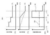
まず、基本となる空調負荷の性質について説明する。式(1)から部屋の温度変化率によって空調負荷が変動することが分かり、これより求めた設定温度・室内温度・空調機熱負荷の関係を示したものが図4である。まず実線で示した負荷401は通常の起動であり、時刻T2(402)に室内温度をY℃にするために、時刻T1(403)に空調機を起動している。通常、空調起動時は一気に目的の温度にするため、時刻T1は時刻T2に近い値となり、これによる大きな温度変化率のためピークが発生している。一方、これよりもっと早い時刻T3(404)に空調機を起動し、設定温度と室内温度変化を緩やかにした負荷が405であり、式(1)から分かるように、目標温度までの到達時間を長くしているため温度変化率が小さくなり、生じる負荷の大きさも小さくなる。
First, the basic properties of the air conditioning load will be described. From equation (1), it can be seen that the air conditioning load varies depending on the rate of change in the temperature of the room, and FIG. 4 shows the relationship between the set temperature, room temperature, and air conditioner heat load obtained from this. First, a
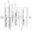
以上の性質を用いた本実施例におけるS304の詳細なフローを図5に示し、その各ステップを以下に説明する。まず、ユーザが指定する上限値qmaxに対して、空調機負荷がとることのできる値を調べるため、上限値qmaxから制御対象となる空調機以外の負荷qremを減じる(S501)。次に、S501で求めた値を使用して各部屋の温度変化率による負荷が満たす条件を、式(2)を用いて求める(S502)。 FIG. 5 shows a detailed flow of S304 in the present embodiment using the above properties, and each step will be described below. First, in order to examine the value that can be taken by the air conditioner load with respect to the upper limit value q max specified by the user, the load q rem other than the air conditioner to be controlled is subtracted from the upper limit value q max (S501). Next, using the value obtained in S501, the condition that the load due to the temperature change rate of each room satisfies is obtained using Equation (2) (S502).
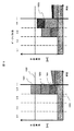
ここで、kは各空調機の番号を表し、qA_Oは式1の右辺で部屋の時間に対する温度変化率による項以外のものを足し合わせたものである。次に、各空調機の起動時刻を同一として少しずつ前の時間にずらしていくことで、時間に対する温度変化率を変え、式2を満たす最もT2に近い時刻TSを決定する(S503)。次に、 解TSが存在するかどうかを判定する (S504)。この判定は、ずらしていく空調機の起動時刻がこれ以上前倒しできないとする時刻に到達しても閾値の超過が防げない場合に解なしとする。解TSが存在した場合は、ピークシフト可の判定をする(S505)。一方、存在しない場合はピークシフト不可判定(S506)をして終了する。これにより、全体負荷がピークを超過しない様な空調スケジュールを作成することが可能となる。図6にこのフローにより実施したピークシフトの状況を示す。ピークシフト前は4つの空調負荷(601〜604)により閾値605を超過している。ここで、前記フローによる方法で空調起動時刻TSを求めると、時刻607となる。なお、式2の演算において閾値605をそのまま用いると予測誤差が生じた場合に閾値超過の恐れがあるが、この閾値からある程度の余裕を持たせた低い値を設定することで対応できる。
Here, k represents the number of each air conditioner, and q A_O is the sum of items other than the term due to the rate of temperature change with respect to the room time on the right side of
本実施例について、以下に示す。本実施例における運転制御システム101は、図3のフローの空調負荷の組合せを求めるステップS304を変更したものとなる。その詳細なフローを図7に示し、そのステップの詳細を以下に示す。なお、本実施例には設定温度を連続的に変化させられない場合(通常のエアコンの様に1℃ずつ等)を対象とする。
This example will be described below. The
まず全体負荷が、ユーザが指定する上限値を超えている時間帯±Δtの部分を、シフト対象領域とし、遅い時刻に存在するものから順に番号を付ける (S701)。ここでΔtについては、シフト対象負荷の時間間隔を考慮し、数秒・数分等の値を設定するもので、0としても良い。次に、S701で得られたシフト対象領域において、負荷の最大値を持つ空調機をシフト対象空調機として指定する (S702)。次に、シフト対象領域番号iを1〜N までについてループを回す。これは、S701より、時間的に遅いピークから順番にシフトを行うことを意味する(S703)。続いて、シフト対象領域iに存在するシフト対象空調機jについて予め定めた優先順位でループを回す(S704)。この優先順位は予めユーザにより任意に指定するものとしても良いし、または空調機熱負荷最大値の大きさや、対象空調機の冷暖房容量により順位づけを行ったものでもよい。続いて、現在対象となっている空調機iの負荷を、熱負荷演算部204を用いて漸次設定温度を変えた負荷へと変更する(S705)。 First, the portion of the time zone ± Δt where the total load exceeds the upper limit value designated by the user is set as a shift target region, and numbers are added in order from those existing at a later time (S701). Here, Δt is set to a value such as several seconds or several minutes in consideration of the time interval of the load to be shifted, and may be 0. Next, in the shift target area obtained in S701, the air conditioner having the maximum load value is designated as the shift target air conditioner (S702). Next, the loop is rotated for the shift target area number i from 1 to N. This means that the shift is performed sequentially from the peak later in time than S701 (S703). Subsequently, the loop is rotated with a predetermined priority for the shift target air conditioner j existing in the shift target area i (S704). This priority may be arbitrarily designated by the user in advance, or may be prioritized according to the maximum value of the air conditioner heat load or the air conditioning capacity of the target air conditioner. Subsequently, the load of the air conditioner i that is the current target is changed to a load that gradually changes the set temperature using the thermal load calculation unit 204 (S705).
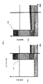
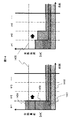
ここで、熱負荷演算部204が生成する漸次設定温度を変化させた場合の負荷について以下に示す。まず、図8に通常の空調機起動時における設定温度、室内温度、空調機熱負荷について示したグラフを示す。目標時刻(例えば始業時刻)T2(801)に、部屋112の室温を目標温度Y℃(803)にするには、空調機111の通常の予冷(または予熱)では目標温度Y℃(803)を設定温度としたときに、X℃の室温がY℃になる最小の時間間隔をもたせた時刻T1(802)に空調機111を起動する。そのため、空調機起動時刻T1から目標時刻T2にかけて、空調機熱負荷のピーク804が現れる。これは式(1)における温度変化率の項によるもので、X℃とY℃の差分が大きい程、空調機111の出力が大きくなり、温度変化は急峻となり、一時的な負荷が大きくなる。一方、S705で熱負荷演算部204が再演算する負荷は、一時的な負荷の増大を防ぐために、各部屋112の設定温度を、室温より所定温度低い温度(暖房の場合は所定温度高い温度である。本実施例では、所定温度を1℃とする)に設定し、室温が設定温度に達するごとに、設定温度を所定温度低い温度(暖房の場合は所定温度高い温度)に設定することを、室温が目標温度Y℃に達するまで繰り返した場合の空調負荷を計算する。時間変化する空調負荷はS301と同様にして求める。この空調負荷について図9を用いて説明する。始業時刻T2に室内温度が目標温度Y℃に到達するような空調起動時刻をT3(903)として、設定温度を所定温度(1℃)ずつ変化させて空調機111を運転している。この場合、室温と設定温度の温度差が常に小さいので、室温の変化率が緩やかになり、式(1)から分かるように空中負荷の瞬時値は減少する。一方、目標温度までの到達時間はT2-T1からT2-T3と長くなる。そのため、空調熱負荷は901から902に変化する。
Here, the load when the gradually set temperature generated by the thermal
この漸次設定温度を下げていく熱負荷の生成は熱負荷演算部204が行うが、それはS705において順次演算する、あるいはシフト対象空調機が定まるS702の後に全てのシフト対象空調機に対して予め作成しておく、あるいは全空調機についてS701の演算前に作成しておく等、どの箇所で演算しても良い。求め方としては式1を用いて微分方程式を解く、あるいは起動時刻を順次前の時間にずらしていくことで目標とする時間に目標とする温度に到達できるような時刻を見つけ、その負荷とする等の方法を用いる。
The heat
再び図7に戻り、S705の次のステップにおいて早い時刻に存在する次のシフト対象領域終了時間以降で、前述のS705における空調機熱負荷の変更によって一時的な閾値の超過がなくなっているかどうかを確認する(S706)。超過したままの場合は、S703のループで次の空調機熱負荷に対して順次同じ処理を行って行く。ここで、全てのシフト対象空調機熱負荷に対して実施した後も、一時的な超過がなくならないようであればピークシフト不可判定を行い(S707)、終了する。一方S706において閾値の超過がなくなった場合は、現在対象としているシフト対象領域においてピークシフト可と判定し、次のシフト対象領域に移り、負荷のシフトを行って行く。最終的に全てのシフト対象領域に対してピークシフトが成功した場合には、ピークシフト可判定を行い(S708)、終了する。これにより、熱負荷のピークをシフトすることが可能となる。 Returning to FIG. 7 again, after the next shift target region end time existing at an early time in the next step of S705, it is determined whether or not the temporary threshold has been exceeded due to the change of the air conditioner thermal load in S705 described above. Confirm (S706). If it has exceeded, the same processing is sequentially performed on the next air conditioner heat load in the loop of S703. Here, even if it is performed for all shift target air conditioner heat loads, if it does not disappear temporarily, a peak shift impossibility determination is made (S707) and the process ends. On the other hand, when the threshold value is no longer exceeded in S706, it is determined that the peak shift is possible in the current shift target area, and the process shifts to the next shift target area and shifts the load. If the peak shift has succeeded for all the shift target areas, the peak shift is determined (S708), and the process ends. Thereby, the peak of the heat load can be shifted.
ピークシフト実施前後の例を図10に示す。1001〜1004までが空調負荷であり、残りはベース負荷である。空調負荷の内、下に位置するもの程シフトの優先順位が高いものとする。図7のフローに伴い、優先順位の最も高い空調負荷1001から順に、設定温度を漸次変化させた負荷に変えていき、3つ目の負荷1003を変更した所で全体空調負荷が閾値1005以下となり、一時的な閾値超過がなくなる。そのため、この時の空調負荷がピークシフト後の解として出力される。
An example before and after the peak shift is shown in FIG. 1001 to 1004 are air conditioning loads, and the rest are base loads. Of the air-conditioning loads, the lower the shift priority, the higher the priority. In accordance with the flow in Fig. 7, the
こうしてS304の処理が終了した後、最後にS305で、空調負荷組合せ部205で得られる各空調機111の運転パターン(空調負荷のパターン)に基づいて、冷暖房の運転制御装置101が空調機111または空調機制御システム210に制御指令を出力する。これにより、空調機の運転を制御することで、熱負荷のピークを抑制することが可能となる。ピークシフトが不可となった場合については、シフトを全くしていない最初の状態または途中までの状態の、どちらかを解として出力する。
After the processing of S304 is completed in this way, finally, in S305, based on the operation pattern (air conditioning load pattern) of each air conditioner 111 obtained by the air conditioning
本実施例について、以下に示す。本実施例における運転制御システム101は、図3の空調負荷の組合せを求めるフローのステップS304を変更したものとなる。その処理フローを図11に示す。まず、熱負荷の合計が閾値を超えている時間帯で、負荷の最大値を持つ空調機をシフト対象空調機とする(S1101)。次にシフト対象空調機の起動時刻をゼロ点へと移動した負荷を作成する(S1102)。次にシフト対象となっている空調機の積上げ開始時刻tに対して0から終了時刻Tまで順に処理を行う(S1103)。この終了時刻Tとしては、シフトを行いうる全時間幅かそれ以上の任意の値で良い(最終的にピークシフトの可不可がS1105で定まりループを抜けるため)。次に、優先順位の高い順に、一時的な増段がないようにシフト対象のテンポラリ空調負荷を積んでいく(S1104)。この積み方については、さらに後述の図12のフローに詳細を示す。次にこの結果がピークシフト可であるか不可であるかを判定する(S1105)。可であった場合は、得られた積上げ後のテンポラリ空調負荷を暫定解として更新すると共に、最初のループでは、S1102で全て0点に統一されている空調機起動時刻を1つ先の時刻にずらしたものへと更新する(S1106)。これを繰り返し、最終的にピークシフトが不可となった段階で、最後の暫定解を最終的な解とする(S1107)。1度も解が得られない場合に対しては、暫定解として始めは元の空調負荷を入れておく等で対処する。
This example will be described below. The
次に、S1104の詳細について図12にそのフローを示す。まず全シフト対象空調不可に対して処理を行うためj番目の空調負荷を指定する(S1201)。この順番は予め実施例1の場合と同様に、予めユーザにより任意に指定するものとしても良いし、または空調機熱負荷最大値の大きさや、対象空調機の冷房容量等で順位づけを行ったものでもよい。次に、空調機jの空調負荷移動時間を0 で初期化する(S1202)。次に、空調機jまでとそれ以外のシフト対象外の熱負荷を足し合わせた負荷を導出する(S1203)。次に、S1203で求めた負荷の和が一時的に閾値を超過しているかを判定する(S1204)。超過している場合には、空調機 jの空調負荷を1つ先の時刻にずらしたものとする (S1205)。次に、S1204で作成した空調負荷の起動時刻が、S1102で起動時刻をゼロ点に戻す前の元の負荷の起動時刻より先になるかを判定する(S1206)。先になる場合は、空調負荷を元の起動時刻よりも遅くに立ち上げることになるためピークシフトは不可と判定し、終了する(S1207)。そしてS1204において、閾値を超過していない場合には、空調機iの負荷を固定し、次のシフト対象空調機の負荷のシフトを開始する。 Next, FIG. 12 shows the flow of details of S1104. First, the j-th air conditioning load is designated in order to perform processing for all shift target air conditioning disabled (S1201). As in the case of the first embodiment, this order may be arbitrarily designated by the user in advance, or the order of the air conditioner heat load maximum value, the cooling capacity of the target air conditioner, etc. It may be a thing. Next, the air conditioning load moving time of the air conditioner j is initialized to 0 (S1202). Next, a load obtained by adding the heat loads up to the air conditioner j and the other non-shift targets is derived (S1203). Next, it is determined whether the sum of loads obtained in S1203 temporarily exceeds a threshold value (S1204). If exceeded, the air conditioning load of the air conditioner j is shifted one time ahead (S1205). Next, it is determined whether the activation time of the air conditioning load created in S1204 is earlier than the activation time of the original load before the activation time is returned to the zero point in S1102 (S1206). In the first case, since the air conditioning load is started later than the original activation time, it is determined that peak shift is not possible, and the process ends (S1207). In S1204, if the threshold value is not exceeded, the load of the air conditioner i is fixed, and the shift of the load of the next shift target air conditioner is started.
この処理について、空調負荷の動きを図13,14,15を用いて説明する。まずS1102において、全ての負荷は空調開始点に図13の様に1301から1302へと移動される。続いてS1203において、図14の優先順位の最も高い空調負荷1401とベースの負荷1402を足し合わせた負荷を作成する。ベース負荷1402と空調負荷1401のみが存在する状況となるため、S1204では超過なしと判断される。そのため、このループを抜け、次の空調負荷1403についても同様に足し合わせを行う。続いて空調負荷1404についても同様にして足し合わせると、図14に示すように閾値1405を超過してしまう。そのため、S1205にてこの空調機の起動時刻を1つだけ先へずらす。その状態でS1203を実施すると図14右側の図のように、今度は閾値を超過していないため、S1204の判定により、次の空調機を積み上げ始める。最後の空調負荷1404も時刻t=1より積み上げるが、やはり閾値1405を超えてしまうため、図15の1501に示すようにt=2に積み上げることとなる。この時点で全ての空調機に対するシフトを終えるため、S1201のループを抜け、S1208でピークシフトが可と判断される。そしてS1106にて暫定解をこの積み上げ後の空調負荷に更新すると共に、図13の1302に示した空調負荷を1つだけ先の時刻t=2へとずらす。こうして得られた空調負荷に対して、再度S1104の処理を行って行く。結果、t=2を始点として図15の左側と同様の形で積み上がる負荷ができる。最後に、t=3より積み上げた後に、t=4以降では元の空調起動時刻を遅らせることなくピークをシフトすることは不可とS1206で判断されるため、終了となる。最終的にピークシフト後の解として空調負荷1502が生成される。
Regarding this process, the movement of the air conditioning load will be described with reference to FIGS. First, in S1102, all loads are moved from 1301 to 1302 at the air conditioning start point as shown in FIG. Subsequently, in S1203, a load is created by adding the
t=1から積み上げた解をそのまま時間方向へ並行移動したものを解としないのは、ベース負荷1402に凹凸がある場合に、閾値を超えてしまう恐れがあるためである。
The reason why the solutions accumulated from t = 1 are not translated as parallel solutions in the time direction is that the threshold may be exceeded if the
また本実施例では空調負荷を元の形のまま、時間的に平行移動したものである。そのため、暖房のように時間が早くなるほど負荷が大きくなる場合には、実際の負荷が閾値を超過してしまう可能性がある。そのため、それを避けるために図3のフローを改良した図16に変更することで対応可能である。このフローでは、S304で空調負荷から起動時刻を求めた後に、S1601でピークシフトの正否を判定する。シフトできない場合には、何らかの暫定解を出力して終了する。一方、シフト可であった場合には、S301に戻って再度空調負荷を再演算して、上限超過判定を行う。これにより、シフト後の空調負荷が閾値を超過してしまうことを防ぐことが可能となる。 In this embodiment, the air conditioning load is translated in time with the original shape. Therefore, when the load becomes larger as the time becomes faster as in heating, the actual load may exceed the threshold value. Therefore, in order to avoid this, it can be dealt with by changing the flow of FIG. 3 to FIG. In this flow, after determining the start time from the air conditioning load in S304, whether or not the peak shift is correct is determined in S1601. If the shift is not possible, output some provisional solution and end. On the other hand, if the shift is possible, the process returns to S301, recalculates the air conditioning load, and performs an upper limit excess determination. Thereby, it becomes possible to prevent the air-conditioning load after the shift from exceeding the threshold value.
本実施例について、以下に示す。本実施例は、実施例3における空調負荷積上げの繰り返し計算数を少なくしたもので、後ろの時刻からの積み上げ処理を行う。その処理フローは、図3のステップS304を変更したものとなる。 This example will be described below. In this embodiment, the number of repeated calculations for accumulating the air conditioning load in the third embodiment is reduced, and the stacking process is performed from the later time. The processing flow is obtained by changing step S304 in FIG.
このフローを図17に示す。まず、熱負荷の合計が閾値を超えている時間帯で、負荷の最大値を持つ空調機をシフト対象空調機とする(S1701)。次に、シフト対象空調機の起動時刻を、起動時刻が最も早い空調機の起動時刻Teに合わせるように移動した負荷を作成する(S1702)。この後はTeから開始点まで順に処理を行っていく(S1703)。これは、後ろの時刻から順に負荷を積み上げていくことと対応している。続いて、優先順位の高い順に、一時的な増段がないようにシフト対象のテンポラリ空調負荷を積んでいく(S1704)。この中身はS1104と全く同じであり、その詳細処理も同じ図12のフローに沿って行う。次に、ピークシフトが可である場合には、それを解として出力して終了となる(S1705)。 一方、ピークシフトが不可の場合にはテンポラリ空調負荷配列の開始点を1つ前の時刻にずらしたものへと更新する(S1706)。ここで、起動時刻が開始点0に到達した場合は、ピークシフトが不可であるとして終了する。この時は実施例2と同様に、ピークシフト前の状態を保存しておき解の代わりに出力する等しておく。 This flow is shown in FIG. First, an air conditioner having a maximum load value is set as a shift target air conditioner in a time zone in which the total heat load exceeds the threshold (S1701). Next, a load that is moved so that the start time of the air conditioner to be shifted matches the start time Te of the air conditioner with the earliest start time is created (S1702). Thereafter, processing is sequentially performed from Te to the start point (S1703). This corresponds to increasing the load in order from the later time. Subsequently, the temporary air-conditioning load to be shifted is loaded so that there is no temporary increase in order of priority (S1704). The contents are exactly the same as in S1104, and the detailed processing is also performed according to the same flow of FIG. Next, if the peak shift is possible, it is output as a solution and the process ends (S1705). On the other hand, if peak shift is not possible, the start point of the temporary air conditioning load array is updated to the one shifted to the previous time (S1706). Here, when the activation time reaches the start point 0, it is determined that the peak shift is impossible and the process ends. At this time, as in the second embodiment, the state before the peak shift is stored and output instead of the solution.
この処理について、空調負荷の動きを図18を用いて説明する。まずS1702において、ピーク開始位置は全て等しくt=4であるため、図13にもあるピークシフト前の状態から変化しない。続いてS1703において、優先順位の最も高い空調負荷1801とベースの負荷1802を足し合わせた負荷を作成する。この場合は、図18からも分かるように、S1204で超過なしと判断される。そのため、このループを抜け、次の空調負荷1803についても同様に足し合わせを行う。続いて空調負荷1804についても同様にして足し合わせるが、図18に示すように、この時、閾値1805を超過してしまう。そのため、S1205にて負荷1804の空調機の起動時刻を1つだけ後の時刻へずらすが、この時刻は元の立上げ時刻よりも先になるため、S1207でピークシフトが不可と判定する。これによりS1705を通り、S1706の処理を行う。次のループでは、t=3の位置から空調負荷を積み上げる。この時はt=4までで、図18の右側の図のように負荷を積み上げることが可能となる。そこでこの空調負荷がS1705を得てピークシフト後の解1806となる。
Regarding this processing, the movement of the air conditioning load will be described with reference to FIG. First, in S1702, since all the peak start positions are t = 4, there is no change from the state before the peak shift, which is also in FIG. Subsequently, in S1703, a load obtained by adding the
このように、暫定解を順次作っていく必要がなくなり、S1705でピークシフトが可となった場合に即座に解が得られるため、実施例3と比較して、ピークシフトをより高速に実施することが可能となる。 In this way, it is not necessary to create provisional solutions in sequence, and when the peak shift is enabled in S1705, the solution can be obtained immediately, so the peak shift is performed faster than in Example 3. It becomes possible.
本実施例について、以下に示す。本実施例では、空調機111の起動による空調負荷のピークに対して、空調機111の設定温度を少しずつ変化させる手法と、空調機111の起動時刻をずらす手法とを併用し、さらに温度変化率を一般的にした場合に関して、効果が最大となるように各部屋に最適な分配を求める。 This example will be described below. In this example, the method of changing the set temperature of the air conditioner 111 little by little with respect to the peak of the air conditioning load due to the start of the air conditioner 111 and the method of shifting the start time of the air conditioner 111 are used together. In the case where the rate is generalized, an optimal distribution is obtained for each room so as to maximize the effect.
冷暖房の運転制御システム101の処理は図3と同様のフローでS303まで実施例1〜4と同一である。次にS304において、熱負荷演算部203が各部屋112の空調機111の設定温度を所定温度幅として1℃ずつ変化させていくものと、空調負荷のピークを時間的にずらした空調負荷を演算する。この対象とする空調負荷は、シフト対象空調機を選定しても良いし、シフトを行うことのできる全ての空調機を対象として良い。また、所定温度幅は1℃ずつのみでなく、1℃→2℃や2℃→1℃などの空調機111の温度設定単位の整数倍で、かつその時の室温と目標温度との差分から想定される設定温度の変化のさせ方全てに対して、予め空調負荷を求める部屋112ごとに生成される空調負荷をDijとおく。iは部屋番号、jは空調負荷の各パターンを示す番号である。これを用いると、各部屋でどの空調負荷パターンを選択するかを示す0-1変数γijを用いて、各部屋の空調負荷は以下の式(3)、式(4)で表される。式(4)は、各空調の設定温度の負荷の内、どれか1つを選択することから得られる条件式である。
The processing of the cooling / heating
冷暖房システム全体の熱負荷は、ベースとして存在する空調以外の負荷Bと合わせて以下の式(5)で表されるため、設定した負荷上限値GMAXを超えないようにするためには、式(6)に示す条件が成立する必要がある。 The heat load of the entire air conditioning system is expressed by the following formula (5) together with the load B other than air conditioning existing as a base. Therefore, in order not to exceed the set load upper limit G MAX , the formula The condition shown in (6) must be satisfied.
ここで番号n(熱源設備に付した連続番号)の熱源設備(105)の出力をun、消費エネルギーをEnとして、各々を負荷率x(実出力/定格出力)と起動停止オンオフ変数zとを用いて線形近似すると、式(7)、 式(8)、 式(9)となる。 Here, the output of the heat source facility (105) with the number n (sequential number attached to the heat source facility) is u n , the energy consumption is E n , and the load factor x (actual output / rated output) and the start / stop on / off variable z When linearly approximated using and, Equations (7), (8), and (9) are obtained.
a,b,α、βは係数である。mは、熱源設備の特性を区分線形近似した際の区間の番号を示す。熱源設備は、横軸が負荷率、縦軸が用役量またはエネルギー消費量で示される非線形特性を持つが、本実施例の最適化手法であるように混合整数計画法を用いると、線形の関数しか扱えないため、区分線形近似している。そのため、非線形最適化を行う場合は非線形の特性式を用いる。 a, b, α and β are coefficients. m shows the number of the section at the time of the piecewise linear approximation of the characteristics of the heat source equipment. The heat source equipment has a nonlinear characteristic in which the horizontal axis indicates the load factor and the vertical axis indicates the utility amount or the energy consumption. However, if the mixed integer programming is used as in the optimization method of the present embodiment, the heat source facility is linear. Since only functions can be handled, piecewise linear approximation is used. Therefore, when performing nonlinear optimization, a nonlinear characteristic equation is used.
このとき、冷暖房システム全体の熱負荷と熱源設備の出力が等しいという条件から式(10)の条件が成立する。 At this time, the condition of Expression (10) is established from the condition that the heat load of the entire air conditioning system is equal to the output of the heat source equipment.
これらの条件を制約式とし、式(8)のエネルギーを最小化すべき目的関数とし、熱源設備の負荷率x・起動停止変数z・各空調機がどの負荷になるかを決めるγを変数として、混合整数計画法として解を求めることで、用役出力量が上限値を超えない範囲で熱源設備のエネルギー消費量を最小化するような、空調負荷のパターンを決定できる。これにより、各部屋112の空調機111の設定温度の変化パターンと空調機111の起動時間が分かる。S305では、この結果を元にして空調機111を稼働する。これにより、空調機111の起動による冷温水需要のピークを蓄熱槽を用いずに抑制し、かつ冷暖房センタの熱源設備をできるだけ高効率に運転することが可能となる。
Using these conditions as constraints, the energy in Equation (8) is the objective function that should be minimized, and the load factor x of the heat source equipment x, the start / stop variable z, and γ that determines which load each air conditioner will have, By obtaining a solution as a mixed integer programming method, it is possible to determine an air conditioning load pattern that minimizes the energy consumption of the heat source facility within a range where the utility output amount does not exceed the upper limit value. Thereby, the change pattern of the set temperature of the air conditioner 111 in each
101:冷暖房の運転制御装置、102:冷暖房センタ、103:ポンプ、104:熱源機105についての情報を取得する信号線、105:熱源機、106:流量制御弁、107:熱交換器、108:ポンプ、109:建物、110:流量制御弁、111:空調機、112:部屋、113:温度計、114:一次配管、115:空調機111に制御信号を送る信号線、116:温度計113の情報を取得する信号線。
101: Air-conditioning operation control device, 102: Air-conditioning center, 103: Pump, 104: Signal line for acquiring information about the
Claims (20)
前記熱源設備が対象とする総熱負荷が、予め指定する上限値を超過するときにその超過を判定する負荷上限超過判定部と、前記複数台の空調機の負荷の再演算を行う熱負荷演算部と、前記総熱負荷が前記上限値を超過しない空調スケジュールを決定する空調負荷組合せ部と、前記空調スケジュールに基づいた運転を行う様に前記複数台の空調機に前記制御信号を出力する空調機制御指令設定部とを備え、
前記空調負荷組合せ部が、前記空調スケジュールとして、前記総熱負荷が前記上限値を超えないように、前記複数台の空調機の設定温度とその起動時刻を決定し、
前記空調負荷組合せ部が、前記総熱負荷から前記複数台の空調機による負荷を差し引いた値と、前記上限値とに基づいて、前記複数台の空調機がとることのできる負荷範囲を求め、
前記熱負荷演算部が、前記複数台の空調機の起動時刻を仮におき、その時刻から連続的に設定温度を変化させて目標とする時刻に目標とする温度に到達するようにした時の各室温の変化による熱負荷を演算し、
前記空調負荷組合せ部が、演算した前記熱負荷が前記負荷範囲を一時的に超過しないかを判定し、一時的に超過する場合は起動時刻をさらに前の時刻に移動することを繰り返し、一時的に超過しなくなったときの、前記複数台の空調機の時間に対する設定温度を最終的な設定温度として、この時の仮の起動時刻を起動時刻として、前記空調スケジュールを決定することを特徴とする空調運転制御システム。 Connect to the heat source equipment and a plurality of air conditioners that control the room temperature using cold / hot water from the heat source equipment in response to the control signal,
A load upper limit excess determination unit for determining when the total heat load targeted by the heat source facility exceeds an upper limit value specified in advance, and a heat load calculation for recalculating the loads of the plurality of air conditioners An air conditioning load combination unit that determines an air conditioning schedule in which the total heat load does not exceed the upper limit, and an air conditioner that outputs the control signal to the plurality of air conditioners so as to perform an operation based on the air conditioning schedule A machine control command setting unit,
The air conditioning load combination unit, as the air conditioning schedule, determines a set temperature of the plurality of air conditioners and its start time so that the total heat load does not exceed the upper limit value,
The air conditioning load combination unit obtains a load range that can be taken by the plurality of air conditioners based on a value obtained by subtracting the load from the plurality of air conditioners from the total heat load and the upper limit value,
Each time when the thermal load calculation unit temporarily sets the start time of the plurality of air conditioners, and changes the set temperature continuously from that time to reach the target temperature at the target time Calculate the thermal load due to changes in room temperature,
The air-conditioning load combination unit determines whether the calculated thermal load does not temporarily exceed the load range, and if it temporarily exceeds, the start time is repeatedly moved to a previous time, and temporarily The air conditioning schedule is determined using the set temperature with respect to the time of the plurality of air conditioners as the final set temperature and the provisional start time at this time as the start time. air-conditioning operation control system that.
前記熱源設備が対象とする総熱負荷が、予め指定する上限値を超過するときにその超過を判定する負荷上限超過判定部と、前記複数台の空調機の負荷の再演算を行う熱負荷演算部と、前記総熱負荷が前記上限値を超過しない空調スケジュールを決定する空調負荷組合せ部と、前記空調スケジュールに基づいた運転を行う様に前記複数台の空調機に前記制御信号を出力する空調機制御指令設定部とを備え、
前記空調負荷組合せ部が、前記空調スケジュールとして、前記総熱負荷が前記上限値を超えないように、前記複数台の空調機の設定温度とその起動時刻を決定し、
前記空調負荷組合せ部が、前記複数台の空調機の1台に対して、所定の時刻に当該空調機が対象とする部屋に設定したい目標温度から、所定温度だけ高い(冷房の場合、暖房の場合は低い)前記部屋の温度Tの状態で、仮の時刻より運転を開始するとして、当該空調機の設定温度を目標温度とした場合に前記所定の時刻に前記目標温度に到達しているかを判断し、到達していない場合は順次運転開始時刻を前の時刻にすることで、前記所定の時刻に前記目標温度に到達する最も近い時刻tを当該空調機の目標温度設定時刻として決定し、さらにそれより所定温度高い(低い)温度から、前記時刻tに温度Tになるような時刻を求めて、それを設定温度の設定時刻として決定していく処理を順次繰り返し、所定温度高い温度が、室温を超えた後の設定温度の設定時刻を、当該空調機の起動時刻として決定し、
前記熱負荷演算部は、決定した前記起動時刻に基づいて当該空調機の負荷を再演算して、前記総熱負荷を求め、
前記負荷上限超過判定部が、求めた前記総熱負荷が前記上限値を超過しないかを判定し、
前記空調負荷組合せ部が、前記総熱負荷が前記上限値を超過している場合は予め定めた前記複数の空調機の優先順位に従い、前記複数の空調機の他の1台の空調機に対して負荷を演算して、前記総熱負荷を求め、前記上限値を上回らなくなった時点でその操作を終了することで、前記空調スケジュールを決定することを特徴とする空調運転制御システム。 Connect to the heat source equipment and a plurality of air conditioners that control the room temperature using cold / hot water from the heat source equipment in response to the control signal,
A load upper limit excess determination unit for determining when the total heat load targeted by the heat source facility exceeds an upper limit value specified in advance, and a heat load calculation for recalculating the loads of the plurality of air conditioners An air conditioning load combination unit that determines an air conditioning schedule in which the total heat load does not exceed the upper limit, and an air conditioner that outputs the control signal to the plurality of air conditioners so as to perform an operation based on the air conditioning schedule A machine control command setting unit,
The air conditioning load combination unit, as the air conditioning schedule, determines a set temperature of the plurality of air conditioners and its start time so that the total heat load does not exceed the upper limit value,
The air conditioning load combination unit is higher than a target temperature to be set in a room targeted by the air conditioner at a predetermined time with respect to one of the plurality of air conditioners (in the case of cooling, heating When the temperature T of the room starts operation at a tentative time and the set temperature of the air conditioner is set as the target temperature, the target temperature is reached at the predetermined time. Judgment, if not reached, by sequentially setting the operation start time to the previous time, the closest time t to reach the target temperature at the predetermined time is determined as the target temperature setting time of the air conditioner, Further, from the temperature that is higher (lower) by a predetermined temperature than that, the time at which the temperature T is reached at the time t is obtained, and the process of determining it as the set time of the set temperature is sequentially repeated. Of set temperature after exceeding room temperature A constant time, determined as the start time of the air conditioner,
The thermal load calculation unit recalculates the load of the air conditioner based on the determined startup time to obtain the total heat load,
The load upper limit excess determination unit determines whether the obtained total heat load does not exceed the upper limit value,
When the total heat load exceeds the upper limit value, the air conditioning load combination unit follows the predetermined priority order of the plurality of air conditioners, and the other one air conditioner by calculating the load Te, the calculated total heat load, by ending the operation at the time no longer exceed the upper limit value, air-conditioning operation control system that is characterized in that determining the air conditioning schedule.
前記熱源設備が対象とする総熱負荷が、予め指定する上限値を超過するときにその超過を判定する負荷上限超過判定部と、前記複数台の空調機の負荷の再演算を行う熱負荷演算部と、前記総熱負荷が前記上限値を超過しない空調スケジュールを決定する空調負荷組合せ部と、前記空調スケジュールに基づいた運転を行う様に前記複数台の空調機に前記制御信号を出力する空調機制御指令設定部とを備え、
前記空調負荷組合せ部が、所定の時刻に前記複数の空調機が対象とする部屋に設定する目標温度を設定温度に維持し、前記複数の各空調機の起動時刻を変化させ、
前記空調負荷組合せ部が、前記複数台の空調機の負荷を、前記複数台の各空調機が起動可能と設定する最も早い時刻に起動するとした空調負荷を、前記熱負荷演算部が作成した空調負荷を時間に対して並行移動することにより作成し、予め定めておく優先順位の高い空調機から順に、前記総熱負荷から前記複数台の空調機以外の空調負荷を引いた空調機以外の熱負荷と足し合わせ、前記上限値を一時的に超過した場合には、現在足し合わせている前記複数台の空調機の空調負荷を所定時間だけ進めた位置にずらして足し合わせ、この処理を一時的な上限の超過がなくなるまで繰り返し、一時的な上限の超過がなくなったら、前記複数台の各空調機の負荷を、起動可能と設定する最も早い時刻より所定時間だけ進んだ時刻に起動するとした空調負荷を時間に対する並行移動を行うことで作成し、平行移動した前記空調負荷に対して前記足し合わせ処理を行い、さらに所定時間だけ進んだ時刻に起動する空調負荷を作成し、この処理を順次繰り返し、足し合わせる前記複数台の空調機の起動時刻が移動を行う前の前記複数台の空調機の起動時刻と一致しても一時的な上限の超過を避けられなくなるまで繰り返し、その前までに得られている空調負荷の組合せから前記空調スケジュールを決定することを特徴とする空調運転制御システム。 Connect to the heat source equipment and a plurality of air conditioners that control the room temperature using cold / hot water from the heat source equipment in response to the control signal,
A load upper limit excess determination unit for determining when the total heat load targeted by the heat source facility exceeds an upper limit value specified in advance, and a heat load calculation for recalculating the loads of the plurality of air conditioners An air conditioning load combination unit that determines an air conditioning schedule in which the total heat load does not exceed the upper limit, and an air conditioner that outputs the control signal to the plurality of air conditioners so as to perform an operation based on the air conditioning schedule A machine control command setting unit,
The air conditioning load combination unit maintains a target temperature set in a room targeted by the plurality of air conditioners at a predetermined time at a set temperature, and changes a start time of each of the plurality of air conditioners,
The air conditioning load created by the thermal load calculation unit is the air conditioning load that the air conditioning load combination unit starts the load of the plurality of air conditioners at the earliest time that each of the plurality of air conditioners is set to be startable. Heat generated by moving the load in parallel with time, and heat from other than the air conditioner obtained by subtracting the air conditioner load other than the plurality of air conditioners from the total heat load in order from the air conditioner having a higher priority order. If the upper limit value is temporarily exceeded when the load is added, the air-conditioning load of the plurality of air conditioners currently added is shifted to the position advanced by a predetermined time, and the process is temporarily added. Repeat until the upper limit is no longer exceeded, and when the temporary upper limit is no longer exceeded, the air conditioner that starts the load of each of the plurality of air conditioners at a time advanced by a predetermined time from the earliest time set to be startable A load is created by performing parallel movement with respect to time, the addition processing is performed on the parallelly moved air conditioning load, and an air conditioning load that is activated at a time advanced by a predetermined time is created, and this processing is sequentially repeated. If the start time of the plurality of air conditioners to be added coincides with the start time of the plurality of air conditioners before moving, it is repeated until it is unavoidable that the upper limit is temporarily exceeded. air-conditioning operation control system that is characterized in that determining the air conditioning schedule from a combination of air conditioning load being.
前記負荷上限超過判定部が、前記上限値を超過しているかを判定し、
超過している場合は、前記空調負荷組合せ部が、再度前記複数台の空調機の前記空調スケジュールを決定することを特徴とする請求項5記載の空調運転制御システム。 The heat load calculation unit calculates a total heat load based on the determined air conditioning schedule,
The load upper limit excess determination unit determines whether the upper limit value is exceeded,
The air conditioning operation control system according to claim 5 , wherein, if it exceeds, the air conditioning load combination unit again determines the air conditioning schedule of the plurality of air conditioners.
前記熱源設備が対象とする総熱負荷が、予め指定する上限値を超過するときにその超過を判定する負荷上限超過判定部と、前記複数台の空調機の負荷の再演算を行う熱負荷演算部と、前記総熱負荷が前記上限値を超過しない空調スケジュールを決定する空調負荷組合せ部と、前記空調スケジュールに基づいた運転を行う様に前記複数台の空調機に前記制御信号を出力する空調機制御指令設定部とを備え、
前記空調負荷組合せ部が、所定の時刻に前記複数の空調機が対象とする部屋に設定する目標温度を設定温度に維持し、前記複数の各空調機の起動時刻を変化させ、
前記熱負荷演算部が、前記複数台の空調機の中で最も早い時刻に起動する空調機の起動時刻に、起動するとした空調負荷を求め、
前記空調負荷組合せ部が、前記複数台の空調機の負荷を、前記熱負荷演算部が求めた前記空調負荷を時間に対して並行移動することにより作成し、予め定めておく優先順位の高い空調機から順に、前記総熱負荷から前記複数台の空調機以外の空調負荷を引いた空調機以外の熱負荷と足し合わせ、前記上限値を一時的に超過した場合には、足し合わせ途中の前記複数台の空調機の空調負荷を所定時間だけ進めた位置にずらして足し合わせ、この処理を一時的な上限の超過がなくなるまで繰り返し、
足し合わせ途中の前記複数台の空調機の起動時刻が移動を行う前の前記複数台の空調機の起動時刻と一致しても一時的な上限の超過を避けられない場合は、各空調機の負荷を、前記複数台の空調機の中で最も早い時刻より所定時間だけ前の時刻に起動するとした負荷を作成し、これに対して前記足し合わせ処理を行い、この処理を順次繰り返し、一時的な上限の超過がなくなった時点の空調負荷の組合せから前記空調スケジュールを決定することを特徴とする空調運転制御システム。 Connect to the heat source equipment and a plurality of air conditioners that control the room temperature using cold / hot water from the heat source equipment in response to the control signal,
A load upper limit excess determination unit for determining when the total heat load targeted by the heat source facility exceeds an upper limit value specified in advance, and a heat load calculation for recalculating the loads of the plurality of air conditioners An air conditioning load combination unit that determines an air conditioning schedule in which the total heat load does not exceed the upper limit, and an air conditioner that outputs the control signal to the plurality of air conditioners so as to perform an operation based on the air conditioning schedule A machine control command setting unit,
The air conditioning load combination unit maintains a target temperature set in a room targeted by the plurality of air conditioners at a predetermined time at a set temperature, and changes a start time of each of the plurality of air conditioners,
The thermal load calculation unit obtains the air conditioning load to be activated at the activation time of the air conditioner activated at the earliest time among the plurality of air conditioners,
The air conditioning load combination unit creates a load of the plurality of air conditioners by moving the air conditioning load obtained by the thermal load calculation unit in parallel with respect to time, and has a predetermined high priority. In order from the machine, the heat load other than the air conditioner obtained by subtracting the air conditioner load other than the plurality of air conditioners from the total heat load, and when the upper limit is temporarily exceeded, Shift the air conditioning load of multiple air conditioners to the position advanced by a predetermined time and add them, and repeat this process until the temporary upper limit is no longer exceeded.
If the start time of the plurality of air conditioners in the middle of addition is the same as the start time of the plurality of air conditioners before moving, it is unavoidable to temporarily exceed the upper limit. A load that is to be activated at a time that is a predetermined time before the earliest time among the plurality of air conditioners is created, the addition process is performed on the load, and this process is sequentially repeated to temporarily air-conditioning operation control system of a combination of air conditioning load at the time the excess runs out of such upper limit shall be the determining means determines the air-conditioning schedule.
前記負荷上限超過判定部が、前記熱負荷演算部が演算した前記総熱負荷が前記上限値を超過しているかを判定し、
演算した前記総熱負荷が前記上限値を超過している場合に、空調負荷組合せ部は再度前記空調機の前記空調スケジュールを決定することを特徴とする請求項8記載の空調運転制御システム。 The heat load calculation unit calculates a total heat load based on the determined air conditioning schedule,
The load upper limit excess determination unit determines whether the total heat load calculated by the thermal load calculation unit exceeds the upper limit value,
The air conditioning operation control system according to claim 8 , wherein the air conditioning load combination unit determines the air conditioning schedule of the air conditioner again when the calculated total heat load exceeds the upper limit value.
前記熱源設備が対象とする総熱負荷が、予め指定する上限値を超過するときにその超過を判定する負荷上限超過判定部と、前記複数台の空調機の負荷の再演算を行う熱負荷演算部と、前記総熱負荷が前記上限値を超過しない空調スケジュールを決定する空調負荷組合せ部と、前記空調スケジュールに基づいた運転を行う様に前記複数台の空調機に前記制御信号を出力する空調機制御指令設定部とを備え、
前記熱負荷演算部が、前記複数台の各空調機の設定温度を逐次変化させた第1の空調負荷と、前記複数台の各空調機の起動時刻を元の起動時刻よりも早い時刻に起動するとした第2の空調負荷を演算し、
前記空調負荷組合せ部が、前記第1及び前記第2の空調負荷の内、前記複数台の各空調機がどちらの負荷をとるか、また早い時刻に起動するとした負荷の場合はその起動時刻がいつであるかを最適化の対象として、総CO2排出量等の指標を目的関数とした最適化問題を混合整数計画問題等の最適化手法を用いて解くことで空調負荷の組合せを求め、前記空調スケジュールを決定することを特徴とする空調運転制御システム。 Connect to the heat source equipment and a plurality of air conditioners that control the room temperature using cold / hot water from the heat source equipment in response to the control signal,
A load upper limit excess determination unit for determining when the total heat load targeted by the heat source facility exceeds an upper limit value specified in advance, and a heat load calculation for recalculating the loads of the plurality of air conditioners An air conditioning load combination unit that determines an air conditioning schedule in which the total heat load does not exceed the upper limit, and an air conditioner that outputs the control signal to the plurality of air conditioners so as to perform an operation based on the air conditioning schedule A machine control command setting unit,
The thermal load calculation unit starts the first air conditioning load obtained by sequentially changing the set temperature of each of the plurality of air conditioners and the start time of each of the plurality of air conditioners at an earlier time than the original start time. Then, calculate the second air conditioning load,
In the case where the air-conditioning load combination unit determines which of the first and second air-conditioning loads each of the plurality of air-conditioners takes, and if the load is activated at an earlier time, the activation time is As a target of optimization, the optimization problem using an index function such as total CO2 emissions as an objective function is solved using an optimization method such as a mixed integer programming problem to obtain a combination of air conditioning loads. air-conditioning operation control system that is characterized in that determining the air conditioning schedule.
前記空調運転制御システムは、前記複数台の空調機による負荷とそれ以外の熱負荷の和である総熱負荷が、予め指定した上限値を超過するとき、前記複数台の各空調機の負荷を再演算し、前記総熱負荷が前記上限値を超過しない空調スケジュールを決定し、それに基づいた運転を行う様に、前記複数台の空調機に前記制御信号を出力し、
前記空調運転制御システムは、前記空調スケジュールとして、前記総熱負荷が前記上限値を超えないように、前記複数台の空調機の設定温度とその起動時刻を決定し、
前記空調運転制御システムは、前記総熱負荷から前記複数台の空調機による負荷を差し引いた値と、前記上限値とに基づいて、前記複数台の空調機がとることのできる負荷範囲を求め、前記複数台の空調機の起動時刻を仮におき、その時刻から連続的に設定温度を変化させて目標とする時刻に目標とする温度に到達するようにした時の各室温の変化による熱負荷を演算し、
演算した前記熱負荷が前記負荷範囲を一時的に超過しないかを判定し、一時的に超過する場合は起動時刻をさらに前の時刻に移動することを繰り返し、一時的に超過しなくなったときの、前記複数台の空調機の時間に対する設定温度を最終的な設定温度として、この時の仮の起動時刻を起動時刻として、前記空調スケジュールを決定することを特徴とする空調運転制御方法。 An air conditioning operation control method in an air conditioning operation control system connected to a plurality of air conditioners that control room temperature using cold / hot water from the heat source facility in response to a heat source facility,
The air conditioning operation control system determines the load of each of the plurality of air conditioners when the total heat load, which is the sum of the load of the plurality of air conditioners and the other heat load, exceeds a predetermined upper limit value. Recalculate, determine an air conditioning schedule in which the total heat load does not exceed the upper limit, and output the control signal to the plurality of air conditioners so as to perform an operation based thereon,
The air conditioning operation control system determines the set temperature of the plurality of air conditioners and the start time thereof so that the total heat load does not exceed the upper limit value as the air conditioning schedule,
The air conditioning operation control system, wherein a value obtained by subtracting the load of the plurality of air conditioners from the total heat load, on the basis of the upper limit value, the negative Nihan circumference which can be the plurality of air conditioners take The heat generated by the change in each room temperature when the start time of the plurality of air conditioners is temporarily determined and the set temperature is continuously changed from that time to reach the target temperature at the target time. Calculate the load
It is determined whether the calculated thermal load does not temporarily exceed the load range, and if it exceeds temporarily, the start time is repeatedly moved to the previous time, and when it does not temporarily exceed , said plurality set temperatures for the time of the air conditioner as the final set temperature, as the temporary activation time when to start at this time air conditioning operation control method you characterized by determining the air conditioning schedule.
前記空調運転制御システムは、前記複数台の空調機による負荷とそれ以外の熱負荷の和である総熱負荷が、予め指定した上限値を超過するとき、前記複数台の各空調機の負荷を再演算し、前記総熱負荷が前記上限値を超過しない空調スケジュールを決定し、それに基づいた運転を行う様に、前記複数台の空調機に前記制御信号を出力し、
前記空調運転制御システムは、前記空調スケジュールとして、前記総熱負荷が前記上限値を超えないように、前記複数台の空調機の設定温度とその起動時刻を決定し、
前記空調運転制御システムは、前記複数台の空調機の1台に対して、所定の時刻に当該空調機が対象とする部屋に設定したい目標温度から、所定温度だけ高い(冷房の場合、暖房の場合は低い)前記部屋の温度Tの状態で、仮の時刻より運転を開始するとして、当該空調機の設定温度を目標温度とした場合に前記所定の時刻に前記目標温度に到達しているかを判断し、到達していない場合は順次運転開始時刻を前の時刻にすることで、前記所定の時刻に前記目標温度に到達する最も近い時刻tを当該空調機の目標温度設定時刻として決定し、
さらにそれより所定温度高い(低い)温度から、前記時刻tに温度Tになるような時刻を求めて、それを設定温度の設定時刻として決定していく処理を順次繰り返し、所定温度高い(低い)温度が、室温を超えた後の設定温度の設定時刻を、当該空調機の起動時刻として決定し、
決定した前記起動時刻に基づいて当該空調機の空調負荷を再演算し、前記総熱負荷を求め、求めた前記総熱負荷が前記上限値を超過しないかを判定し、超過している場合は予め定めた前記複数の空調機の優先順位に従い、前記複数の空調機の他の1台の空調機に対して負荷を演算して、前記総熱負荷を求め、前記上限値を上回らなくなった時点でその操作を終了することで、前記空調スケジュールを決定することを特徴とする空調運転制御方法。 An air conditioning operation control method in an air conditioning operation control system connected to a plurality of air conditioners that control room temperature using cold / hot water from the heat source facility in response to a heat source facility,
The air conditioning operation control system determines the load of each of the plurality of air conditioners when the total heat load, which is the sum of the load of the plurality of air conditioners and the other heat load, exceeds a predetermined upper limit value. Recalculate, determine an air conditioning schedule in which the total heat load does not exceed the upper limit, and output the control signal to the plurality of air conditioners so as to perform an operation based thereon,
The air conditioning operation control system determines the set temperature of the plurality of air conditioners and the start time thereof so that the total heat load does not exceed the upper limit value as the air conditioning schedule,
The air conditioning operation control system is higher than a target temperature desired to be set in a room targeted by the air conditioner at a predetermined time with respect to one of the plurality of air conditioners (in the case of cooling, heating When the temperature T of the room starts operation at a tentative time and the set temperature of the air conditioner is set as the target temperature, the target temperature is reached at the predetermined time. Judgment, if not reached, by sequentially setting the operation start time to the previous time, the closest time t to reach the target temperature at the predetermined time is determined as the target temperature setting time of the air conditioner,
Further, from the temperature higher (lower) by a predetermined temperature than that, the time at which the temperature T is reached at the time t is obtained, and the process of determining it as the set time of the set temperature is sequentially repeated, and the predetermined temperature is higher (lower). The set time of the set temperature after the temperature exceeds room temperature is determined as the start time of the air conditioner,
Recalculate the air conditioning load of the air conditioner based on the determined start time, determine the total heat load, determine whether the calculated total heat load does not exceed the upper limit, and if it exceeds According to a predetermined priority order of the plurality of air conditioners, calculate a load for the other one air conditioner of the plurality of air conditioners, obtain the total heat load, and when the upper limit value is not exceeded in that to terminate the operation, air-conditioning operation control method you characterized by determining the air conditioning schedule.
前記空調運転制御システムは、前記複数台の空調機による負荷とそれ以外の熱負荷の和である総熱負荷が、予め指定した上限値を超過するとき、前記複数台の各空調機の負荷を再演算し、前記総熱負荷が前記上限値を超過しない空調スケジュールを決定し、それに基づいた運転を行う様に、前記複数台の空調機に前記制御信号を出力し、
前記空調運転制御システムは、所定の時刻に前記複数の空調機が対象とする部屋に設定する目標温度を設定温度に維持し、前記複数の各空調機の起動時刻を変化させ、
前記空調運転制御システムは、前記複数台の空調機の負荷を、前記複数台の各空調機が起動可能と設定する最も早い時刻に起動するとした空調負荷を、作成済みの空調負荷を時間に対して並行移動することにより作成し、予め定めておく優先順位の高い空調機から順に、前記総熱負荷から前記複数台の空調機以外の空調負荷を引いた空調機以外の熱負荷と足し合わせ、前記上限値を一時的に超過した場合には、現在足し合わせている前記複数台の空調機の空調負荷を所定時間だけ進めた位置にずらして足し合わせ、この処理を一時的な上限の超過がなくなるまで繰り返し、
一時的な上限の超過がなくなったら、前記複数台の各空調機の負荷を、起動可能と設定する最も早い時刻より所定時間だけ進んだ時刻に起動するとした空調負荷を時間に対する並行移動を行うことで作成し、平行移動した前記空調負荷に対して前記足し合わせ処理を行い、さらに所定時間だけ進んだ時刻に起動する空調負荷を作成し、この処理を順次繰り返し、足し合わせる前記複数台の空調機の起動時刻が移動を行う前の前記複数台の空調機の起動時刻と一致しても一時的な上限の超過を避けられなくなるまで繰り返し、その前までに得られている空調負荷の組合せから前記空調スケジュールを決定することを特徴とする空調運転制御方法。 An air conditioning operation control method in an air conditioning operation control system connected to a plurality of air conditioners that control room temperature using cold / hot water from the heat source facility in response to a heat source facility,
The air conditioning operation control system determines the load of each of the plurality of air conditioners when the total heat load, which is the sum of the load of the plurality of air conditioners and the other heat load, exceeds a predetermined upper limit value. Recalculate, determine an air conditioning schedule in which the total heat load does not exceed the upper limit, and output the control signal to the plurality of air conditioners so as to perform an operation based thereon,
The air conditioning operation control system maintains a target temperature set in a room targeted by the plurality of air conditioners at a predetermined time at a set temperature, and changes the start time of each of the plurality of air conditioners,
The air conditioning operation control system sets the air conditioning load that has been started at the earliest time at which each of the plurality of air conditioners is set to be able to start up as the air conditioning load that has already been created with respect to time. In order from high-priority air conditioners that have been determined in advance, in addition to the heat load other than the air conditioner obtained by subtracting the air conditioner load other than the plurality of air conditioners from the total heat load, If the upper limit value is temporarily exceeded, the air conditioning loads of the plurality of air conditioners currently added together are shifted to a position advanced by a predetermined time and added, and this process is temporarily exceeded. Repeat until no more
When the temporary upper limit is no longer exceeded, the air conditioning load that was started at a time advanced by a predetermined time from the earliest time set to be able to start up the load of each of the plurality of air conditioners is moved in parallel with time. The plurality of air conditioners that are created in the above-described process, add the air-conditioning load to the air-conditioning load that has been translated, and create an air-conditioning load that starts at a time advanced by a predetermined time. Even if the start time of the time coincides with the start time of the plurality of air conditioners before moving, it is repeated until it is unavoidable to temporarily exceed the upper limit, and the combination of the air conditioning loads obtained before that time air-conditioning operation control method shall be the determining means determines the air conditioning schedule.
前記空調運転制御システムは、前記複数台の空調機による負荷とそれ以外の熱負荷の和である総熱負荷が、予め指定した上限値を超過するとき、前記複数台の各空調機の負荷を再演算し、前記総熱負荷が前記上限値を超過しない空調スケジュールを決定し、それに基づいた運転を行う様に、前記複数台の空調機に前記制御信号を出力し、
前記空調運転制御システムは、所定の時刻に前記複数の空調機が対象とする部屋に設定する目標温度を設定温度に維持し、前記複数の各空調機の起動時刻を変化させ、
前記空調運転制御システムは、前記複数台の空調機の負荷を、前記複数台の空調機の中で最も早い時刻に起動する空調機の起動時刻に、起動するとして求めた空調負荷を時間に対して並行移動することにより作成し、
予め定めておく優先順位の高い空調機から順に、前記総熱負荷から前記複数台の空調機以外の空調負荷を引いた空調機以外の熱負荷と足し合わせ、前記上限値を一時的に超過した場合には、足し合わせ途中の前記複数台の空調機の空調負荷を所定時間だけ進めた位置にずらして足し合わせ、この処理を一時的な上限の超過がなくなるまで繰り返し、
足し合わせ途中の前記複数台の空調機の起動時刻が移動を行う前の前記複数台の空調機の起動時刻と一致しても一時的な上限の超過を避けられない場合は、前記複数台の各空調機の負荷を、前記複数台の空調機の中で最も早い時刻より所定時間だけ前の時刻に起動するとした負荷を作成し、これに対して前記足し合わせ処理を行い、この処理を順次繰り返し、一時的な上限の超過がなくなった時点の空調負荷の組合せから前記空調スケジュールを決定することを特徴とする空調運転制御方法。 An air conditioning operation control method in an air conditioning operation control system connected to a plurality of air conditioners that control room temperature using cold / hot water from the heat source facility in response to a heat source facility,
The air conditioning operation control system determines the load of each of the plurality of air conditioners when the total heat load, which is the sum of the load of the plurality of air conditioners and the other heat load, exceeds a predetermined upper limit value. Recalculate, determine an air conditioning schedule in which the total heat load does not exceed the upper limit, and output the control signal to the plurality of air conditioners so as to perform an operation based thereon,
The air conditioning operation control system maintains a target temperature set in a room targeted by the plurality of air conditioners at a predetermined time at a set temperature, and changes the start time of each of the plurality of air conditioners,
The air-conditioning operation control system is configured to calculate the air-conditioning load determined to start at the start time of the air-conditioner that starts at the earliest time among the plurality of air-conditioners. Created by moving in parallel,
In order from the air conditioners with a higher priority order set in advance, the total heat load was subtracted from the air conditioner load other than the plurality of air conditioners and added to the heat load other than the air conditioner, and the upper limit value was temporarily exceeded. In this case, the air conditioning load of the plurality of air conditioners in the middle of addition is shifted to the position advanced for a predetermined time and added, and this process is repeated until the temporary upper limit is no longer exceeded,
If the start time of the plurality of air conditioners in the middle of adding the start time of the plurality of air conditioners before moving is unavoidable, the temporary upper limit cannot be avoided. The load of each air conditioner is started at a time that is a predetermined time before the earliest time among the plurality of air conditioners, and the addition process is performed on this load, and this process is sequentially performed. Again, air-conditioning operation control method you characterized by determining the air conditioning schedule from a combination of air conditioning load at the time the excess is lost temporary limit.
前記空調運転制御システムは、前記複数台の空調機による負荷とそれ以外の熱負荷の和である総熱負荷が、予め指定した上限値を超過するとき、前記複数台の各空調機の負荷を再演算し、前記総熱負荷が前記上限値を超過しない空調スケジュールを決定し、それに基づいた運転を行う様に、前記複数台の空調機に前記制御信号を出力し、
前記空調運転制御システムは、前記複数台の各空調機の設定温度を逐次変化させた第1の空調負荷と、前記複数台の各空調機の起動時刻を元の起動時刻よりも早い時刻に起動するとした第2の空調負荷を演算し、前記第1及び前記第2の空調負荷の内、前記複数台の各空調機がどちらの負荷をとるか、また早い時刻に起動するとした負荷の場合はその起動時刻がいつであるかを最適化の対象として、総CO2排出量等の指標を目的関数とした最適化問題を混合整数計画問題等の最適化手法を用いて解くことで空調負荷の組合せを求め、前記空調スケジュールを決定することを特徴とする空調運転制御方法。 An air conditioning operation control method in an air conditioning operation control system connected to a plurality of air conditioners that control room temperature using cold / hot water from the heat source facility in response to a heat source facility,
The air conditioning operation control system determines the load of each of the plurality of air conditioners when the total heat load, which is the sum of the load of the plurality of air conditioners and the other heat load, exceeds a predetermined upper limit value. Recalculate, determine an air conditioning schedule in which the total heat load does not exceed the upper limit, and output the control signal to the plurality of air conditioners so as to perform an operation based thereon,
The air-conditioning operation control system starts the first air-conditioning load obtained by sequentially changing the set temperature of each of the plurality of air conditioners and the start time of each of the plurality of air-conditioners at an earlier time than the original start time. Then, the second air conditioning load is calculated, and among the first and second air conditioning loads, which of the plurality of air conditioners takes, and in the case of a load that starts at an earlier time Combining air conditioning loads by optimizing the start time of the optimization problem and using an optimization method such as a mixed integer programming problem to solve the optimization problem with an index such as total CO2 emissions as an objective function the calculated, air conditioning operation control method you characterized by determining the air conditioning schedule.
Priority Applications (1)
| Application Number | Priority Date | Filing Date | Title |
|---|---|---|---|
| JP2013237360A JP6219138B2 (en) | 2013-11-15 | 2013-11-15 | Air conditioning operation control system and method |
Applications Claiming Priority (1)
| Application Number | Priority Date | Filing Date | Title |
|---|---|---|---|
| JP2013237360A JP6219138B2 (en) | 2013-11-15 | 2013-11-15 | Air conditioning operation control system and method |
Publications (3)
| Publication Number | Publication Date |
|---|---|
| JP2015096795A JP2015096795A (en) | 2015-05-21 |
| JP2015096795A5 JP2015096795A5 (en) | 2016-09-29 |
| JP6219138B2 true JP6219138B2 (en) | 2017-10-25 |
Family
ID=53374162
Family Applications (1)
| Application Number | Title | Priority Date | Filing Date |
|---|---|---|---|
| JP2013237360A Active JP6219138B2 (en) | 2013-11-15 | 2013-11-15 | Air conditioning operation control system and method |
Country Status (1)
| Country | Link |
|---|---|
| JP (1) | JP6219138B2 (en) |
Families Citing this family (1)
| Publication number | Priority date | Publication date | Assignee | Title |
|---|---|---|---|---|
| CN114636212B (en) * | 2022-04-22 | 2024-01-30 | 苏州思萃融合基建技术研究所有限公司 | GRNN-based running control method for multiple water chilling unit systems |
Family Cites Families (3)
| Publication number | Priority date | Publication date | Assignee | Title |
|---|---|---|---|---|
| JPS6329136A (en) * | 1986-07-21 | 1988-02-06 | Mitsubishi Electric Corp | Control system for advance operation of air conditioner |
| JP2004116947A (en) * | 2002-09-27 | 2004-04-15 | Osaka Gas Co Ltd | Air-conditioning operation control system |
| JP4650254B2 (en) * | 2005-12-20 | 2011-03-16 | ダイキン工業株式会社 | Temperature control device for equipment, temperature control system, temperature control method, and temperature control program |
-
2013
- 2013-11-15 JP JP2013237360A patent/JP6219138B2/en active Active
Also Published As
| Publication number | Publication date |
|---|---|
| JP2015096795A (en) | 2015-05-21 |
Similar Documents
| Publication | Publication Date | Title |
|---|---|---|
| JP5908302B2 (en) | Storage energy storage optimization device, optimization method and optimization program | |
| Ma et al. | Predictive control for energy efficient buildings with thermal storage: Modeling, stimulation, and experiments | |
| CN105320118B (en) | Air-conditioning system electricity needs response control mehtod based on cloud platform | |
| JP2019522290A (en) | Variable refrigerant flow system using multilevel model predictive control | |
| JP4552119B2 (en) | Multi air conditioner demand control system | |
| JP6467216B2 (en) | Heat source system management apparatus, heat source system management method, and program | |
| US9702591B2 (en) | Hot water supply system | |
| JP6422710B2 (en) | Operation control apparatus and operation control method for energy network | |
| US11578889B2 (en) | Information processing apparatus and air-conditioning system provided with the same | |
| JP2007127321A (en) | Cold water load factor controller for refrigerator | |
| JP6116097B2 (en) | Thermal storage system and control method thereof | |
| WO2014192849A1 (en) | Air-conditioner control device, air-conditioner control method, and program | |
| JP6219138B2 (en) | Air conditioning operation control system and method | |
| JP2013047597A (en) | Heat pump system, method for controlling the same, and program | |
| JP4650254B2 (en) | Temperature control device for equipment, temperature control system, temperature control method, and temperature control program | |
| JP2014010631A (en) | Device and method for optimal operation control of energy network | |
| JP4446244B2 (en) | Multi air conditioner energy-saving control system | |
| KR102183942B1 (en) | Building heating control device and method for improving the efficiency of floor heating | |
| JP6427317B2 (en) | Heat source equipment control system and heat source equipment control method | |
| JP6782916B2 (en) | Energy system management equipment, energy system management methods, and energy systems | |
| JP3187118B2 (en) | Heat source equipment operation controller | |
| JP5763955B2 (en) | Air conditioning load prediction device and air conditioning load prediction method | |
| JP2019143909A (en) | Control device, air conditioning control system, control method and program | |
| JP2017048991A (en) | Control unit, hot water supply and heating system, control method, and program | |
| EP4086724B1 (en) | Control of cooling and/or of heating |
Legal Events
| Date | Code | Title | Description |
|---|---|---|---|
| A521 | Written amendment |
Free format text: JAPANESE INTERMEDIATE CODE: A523 Effective date: 20160810 |
|
| A621 | Written request for application examination |
Free format text: JAPANESE INTERMEDIATE CODE: A621 Effective date: 20160810 |
|
| A977 | Report on retrieval |
Free format text: JAPANESE INTERMEDIATE CODE: A971007 Effective date: 20170428 |
|
| A131 | Notification of reasons for refusal |
Free format text: JAPANESE INTERMEDIATE CODE: A131 Effective date: 20170509 |
|
| A521 | Written amendment |
Free format text: JAPANESE INTERMEDIATE CODE: A523 Effective date: 20170629 |
|
| TRDD | Decision of grant or rejection written | ||
| A01 | Written decision to grant a patent or to grant a registration (utility model) |
Free format text: JAPANESE INTERMEDIATE CODE: A01 Effective date: 20170829 |
|
| A61 | First payment of annual fees (during grant procedure) |
Free format text: JAPANESE INTERMEDIATE CODE: A61 Effective date: 20170927 |
|
| R150 | Certificate of patent or registration of utility model |
Ref document number: 6219138 Country of ref document: JP Free format text: JAPANESE INTERMEDIATE CODE: R150 |