JP6218629B2 - Easy-open packaging box - Google Patents
Easy-open packaging box Download PDFInfo
- Publication number
- JP6218629B2 JP6218629B2 JP2014024282A JP2014024282A JP6218629B2 JP 6218629 B2 JP6218629 B2 JP 6218629B2 JP 2014024282 A JP2014024282 A JP 2014024282A JP 2014024282 A JP2014024282 A JP 2014024282A JP 6218629 B2 JP6218629 B2 JP 6218629B2
- Authority
- JP
- Japan
- Prior art keywords
- cut
- opening
- packaging box
- line
- turning
- Prior art date
- Legal status (The legal status is an assumption and is not a legal conclusion. Google has not performed a legal analysis and makes no representation as to the accuracy of the status listed.)
- Active
Links
- 238000004806 packaging method and process Methods 0.000 title claims description 22
- 238000005520 cutting process Methods 0.000 claims description 5
- 238000003780 insertion Methods 0.000 description 3
- 230000037431 insertion Effects 0.000 description 3
- 230000001154 acute effect Effects 0.000 description 2
- 238000000034 method Methods 0.000 description 2
- 238000005452 bending Methods 0.000 description 1
- 239000002537 cosmetic Substances 0.000 description 1
- 230000000994 depressogenic effect Effects 0.000 description 1
- 238000009826 distribution Methods 0.000 description 1
- 238000004519 manufacturing process Methods 0.000 description 1
- 239000000123 paper Substances 0.000 description 1
- 230000002093 peripheral effect Effects 0.000 description 1
- 238000007789 sealing Methods 0.000 description 1
- 230000035939 shock Effects 0.000 description 1
Images


Classifications
-
- B—PERFORMING OPERATIONS; TRANSPORTING
- B65—CONVEYING; PACKING; STORING; HANDLING THIN OR FILAMENTARY MATERIAL
- B65D—CONTAINERS FOR STORAGE OR TRANSPORT OF ARTICLES OR MATERIALS, e.g. BAGS, BARRELS, BOTTLES, BOXES, CANS, CARTONS, CRATES, DRUMS, JARS, TANKS, HOPPERS, FORWARDING CONTAINERS; ACCESSORIES, CLOSURES, OR FITTINGS THEREFOR; PACKAGING ELEMENTS; PACKAGES
- B65D5/00—Rigid or semi-rigid containers of polygonal cross-section, e.g. boxes, cartons or trays, formed by folding or erecting one or more blanks made of paper
- B65D5/42—Details of containers or of foldable or erectable container blanks
- B65D5/54—Lines of weakness to facilitate opening of container or dividing it into separate parts by cutting or tearing
- B65D5/5445—Lines of weakness to facilitate opening of container or dividing it into separate parts by cutting or tearing for dividing a tubular body into separate parts
-
- B—PERFORMING OPERATIONS; TRANSPORTING
- B65—CONVEYING; PACKING; STORING; HANDLING THIN OR FILAMENTARY MATERIAL
- B65D—CONTAINERS FOR STORAGE OR TRANSPORT OF ARTICLES OR MATERIALS, e.g. BAGS, BARRELS, BOTTLES, BOXES, CANS, CARTONS, CRATES, DRUMS, JARS, TANKS, HOPPERS, FORWARDING CONTAINERS; ACCESSORIES, CLOSURES, OR FITTINGS THEREFOR; PACKAGING ELEMENTS; PACKAGES
- B65D5/00—Rigid or semi-rigid containers of polygonal cross-section, e.g. boxes, cartons or trays, formed by folding or erecting one or more blanks made of paper
- B65D5/42—Details of containers or of foldable or erectable container blanks
- B65D5/54—Lines of weakness to facilitate opening of container or dividing it into separate parts by cutting or tearing
- B65D5/5405—Lines of weakness to facilitate opening of container or dividing it into separate parts by cutting or tearing for opening containers formed by erecting a blank in tubular form
- B65D5/542—Lines of weakness to facilitate opening of container or dividing it into separate parts by cutting or tearing for opening containers formed by erecting a blank in tubular form the lines of weakness being provided in the container body
Landscapes
- Engineering & Computer Science (AREA)
- Mechanical Engineering (AREA)
- Cartons (AREA)
Description
この発明は、商品の包装に使用される紙箱であって、容易に開封できる機能を備えたものに関する。 The present invention relates to a paper box that is used for packaging products and has a function that can be easily opened.
従来、下記特許文献1には、図7に示すように、一対の側板51から内蓋フラップ53及び外蓋フラップ54を、他対の端板52から端フラップ55をそれぞれ延出し、外蓋フラップ54には、切目と繋部とが断続する切目線57を中央部から一方の側板51の両端方向へハ字状に入れると共に、その中央部に円弧状の切目線58を入れ、切目線58の内側領域を開封開始部59とした包装箱が記載されている。
Conventionally, in
この包装箱により食品等の商品を包装する際には、端フラップ55を内側へ折り曲げた後、内蓋フラップ53及び外蓋フラップ54を順次重ねるように折り曲げ、外蓋フラップ54を切目線58の先端側で内蓋フラップ53に貼り合わせて封緘する。
When packaging a product such as food in this packaging box, the
このように封緘した包装箱を開封する際には、開封開始部59を押し込んで、外蓋フラップ54を窪むように撓ませると、これに伴い、切目線57の繋部が破断し、切目線57に沿って外蓋フラップ54が切断されるので、内蓋フラップ53及び外蓋フラップ54を開くことができる。
When opening the sealed packaging box in this way, if the
しかしながら、上記のような包装箱は、開封状態で複数の面に亘って大きく開口させることができず、トレイ状態として商品を展示する用途に使用することができない。 However, the packaging box as described above cannot be widely opened across a plurality of surfaces in an opened state, and cannot be used for displaying products in a tray state.
そこで、この発明は、商品の展示作業等に際し、容易に開封して大きく開口させることができる包装箱を提供することを課題とする。 In view of this, an object of the present invention is to provide a packaging box that can be easily opened and greatly opened when a product is displayed.
上記課題を解決するため、この発明は、壁面に切目と繋部とが断続する切目線を入れ、切目線に臨む開封開始部を起点として壁面に力を作用させ、繋部の破断に伴い、切目線に沿って壁面を切断することにより開封する包装箱において、前記切目線の開封開始部が臨む部分から離れた位置に、方向が変化する変向部を設け、変向部の内側に臨む部分を、押込に伴い繋部が破断する開封補助部としたのである。 In order to solve the above-mentioned problem, this invention puts a cut line between the cut line and the connection part on the wall surface, causes a force to act on the wall surface from the opening start part facing the cut line, and along with the breakage of the connection part, In the packaging box that is opened by cutting the wall surface along the cut line, a turning part that changes direction is provided at a position away from the part where the opening start part of the cut line faces, and faces the inside of the turning part. The part was made into the opening assistance part which a connection part fractures | ruptures by pushing.
また、前記開封補助部に、その押込を容易にする誘導罫線を入れたのである。 Moreover, the guide ruled line which makes the pushing easy is put in the said opening assistance part.
さらに、前記切目線における変向部の繋部の寸法を大きく設定し、他の部分の繋部の寸法を小さく設定したのである。 Furthermore, the dimension of the connecting part of the turning part in the cut line is set to be large, and the dimension of the connecting part of the other part is set to be small.
この発明に係る包装箱では、開封する際、まず開封補助部を押し込んで、その部分が臨む切目線の変向部の繋部を破断させると、開封開始部を起点として壁面に僅かに力を作用させるだけで、切目線の他の部分の繋部を破断させ、大きく開口した状態で、商品を露出させて展示することができる。 In the packaging box according to the present invention, when opening, firstly opening the opening assisting part and breaking the connecting part of the turning part of the cut line facing the part, a slight force is applied to the wall surface starting from the opening start part. By simply making it act, it is possible to break the connecting portion of the other part of the score line and expose the product in a state where it is greatly opened.
以下、この発明の実施形態を図1〜図5に基づいて説明する。 Hereinafter, embodiments of the present invention will be described with reference to FIGS.
この包装箱は、高さが奥行より大きい深型のものであり、デルタフルートと呼ばれる厚さ約2mmの段ボールを材料として、図1に示すブランクから形成される。 This packaging box is of a deep type whose height is greater than the depth, and is formed from a blank shown in FIG. 1 using corrugated cardboard having a thickness of about 2 mm called a delta flute.
このブランクでは、前面板1の一方の側端に側面板2、後面板3及び側面板2が順次横方向に連設され、前面板1の他方の側端に継代片4が連設されている。一対の側面板2の下端には底板5が、前面板1及び後面板3の下端には片側に斜め方向の折目線を有する底板6がそれぞれ連設されている。また、一対の側面板2の上端には蓋受片7が連設され、前面板1の上端には蓋板8及び差込片9が順次連設されている。
In this blank, the
前面板1及びこれに繋がる一方の側面板2並びに継代片4と他方の側面板2には、切目と繋部とが断続する切目線10が入れられている。
The
切目線10は、前面板1、側面板2の前部となる部分及び継代片4の下部で横方向に延びる横切部10aと、側面板2の後部となる部分で縦方向に延びる縦切部10bと、横切部10aと縦切部10bとに接続され方向が変化するように湾曲した変向部10cと、縦切部10bの上端から側面板2と蓋受片7の境界に沿って後面板3へ延びる上切部10dとから構成される。
The
横切部10a、縦切部10b及び上切部10dは、直線又は僅かに湾曲した切目が断続するミシン目状とされ、変向部10cは、切断の始端となる中央部の切目を挟んで、ジッパ型と呼ばれる鉤状の切目が対称に断続するものとされている。
The
前面板1において、横切部10aは、下向きに凸となるように大きな曲率で湾曲し、横切部10aの中央部の上側に臨む部分は、開封開始部11とされている。開封開始部11は、横切部10aの切目から上方へ向けて切目11aを入れ、その両側に円弧状の誘導罫線11bを入れて形成されている。
In the
側面板2において、横切部10aは、後面板3側へかけて緩い傾斜で上昇し、縦切部10bは、垂直となっている。
In the
そして、変向部10cの内側に臨む部分は、開封補助部12とされ、開封補助部12には、その押し込みを容易にするため、横切部10aと縦切部10bの変向部10cとの接続部分間に亘る誘導罫線12aが入れられている。誘導罫線12aは、段ボールの裏面側から押圧した押罫とされ、その両端部は斜線の中間部より屈曲して深い角度で横切部10a及び縦切部10bへ接近している。
And the part which faces the inside of the turning
ここで、図2に示すように、切目線10における変向部10cの繋部の寸法αは、他の部分の繋部の寸法βよりも大きく設定されている。具体的には、寸法αは4.3mm程度とされ、縦切部10bの寸法βは2mm程度とされている。
Here, as shown in FIG. 2, the dimension α of the connecting portion of the turning
一般には、変向部10cの繋部は、その寸法αを3.5mm以上として、少なくとも2個以上設け、他の部分の繋部は、その寸法βを変向部10cの繋部の寸法αよりも小さくして、変向部10cの繋部よりも長いピッチで設けることとする。
In general, at least two connecting portions of the turning
このようなブランクから成る包装箱は、製造に際し、前面板1と一方の側面板2との境界及び後面板3と他方の側面板2との境界に沿って折り曲げ、継代片4を他方の側面板2に貼り付けると共に、底板6を斜め方向の折目線に沿って折り返した状態で、その折返部を底板5に貼り付けて折畳状態としておく。この折曲及び貼着工程は、既存のグルアを使用して行うことができるので、別途設備投資が必要となることはない。
A packaging box made of such a blank is bent along the boundary between the
そして、レトルト食品等の商品を包装する際には、図3に示すように、前面板1、一対の側面板2及び後面板3から角筒状の周壁を形成し、各一対の底板5,6から底壁を形成して、商品を収納した後、蓋受片7を内側方向へ折り曲げ、蓋板8を後方へ折り曲げて蓋受片7に重ね、差込片9を後面板3と蓋受片7の間に差し込んで封緘する。
And when packaging goods, such as a retort food, as shown in FIG. 3, a square cylinder-shaped surrounding wall is formed from the
一方、店頭で商品を展示する際には、まず、図4に示すように、開封補助部12を押し込んで、切目線10の変向部10cの繋部を破断させ、次に、図5に示すように、開封開始部11を押し込んで、前面板1の横切部10aより上方の部分を手前に引き上げ、横切部10a及び縦切部10bの繋部を破断させ、上切部10dの繋部も破断させる。
On the other hand, when displaying the product at the store, first, as shown in FIG. 4, the
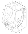
これに伴い、前面板1の横切部10aより上方部分と、その両側に連なる側面板2の横切部10a及び縦切部10bより上方前部と、これらに連なる蓋受片7、蓋板8及び差込片9とを一体として取り去ると、図6に示すように、前面、両側面及び天面が大きく開口したトレイ状部分が残存し、トレイ状部分から商品Gが露出した展示状態となる。
Accordingly, the upper portion than the
このように、上記包装箱では、切目線10の変向部10cに開封補助部12が臨んでいるので、開封する際、開封補助部12を押し込むと、変向部10cの繋部を容易に破断させることができ、その後、開封開始部11を起点として前面板1に僅かな引上力を作用させるだけで、横切部10a、縦切部10b及び上切部10dの繋部を破断させ、大きく開口した状態で、商品Gを露出させて展示することができる。
Thus, in the said packaging box, since the
また、変向部10cの繋部は、ある程度大きくし、またピッチを短くしても簡単に破断するので、変向部10cの繋部を大きく、ピッチを短く設定して、物流過程における耐衝撃性を確保しつつ、切目線10の他の部分の繋部を小さく、ピッチを長く設定して、開封の容易性を向上させることができる。
Further, since the connecting portion of the
そして、この実施形態のように、横切部10a、縦切部10b及び上切部10dの繋部を小さく、ピッチを長く設定しておくと、展示状態としたとき、残存するトレイ状部分において、切目線10のこれらの部分の繋部が破断した跡が目立たないので、美粧性に優れた展示ができる。
And, as in this embodiment, if the connecting portion of the
なお、上記実施形態では、天面がタックエンド式のものを例示したが、天面の封緘構造は、周壁各面の上端から延びるフラップを貼り合わせて封緘するシールエンド式としてもよい。この場合、展示状態とする際、天面のフラップを切断できるように、切目線10の上切部10dを入れるとよい。
In the above embodiment, the top surface has a tack end type, but the sealing structure on the top surface may be a seal end type in which a flap extending from the upper end of each surface of the peripheral wall is bonded and sealed. In this case, when the display state is set, an
また、開封補助部12を両側面に設けたものを例示したが、展示状態で開口させる面が1面又は2面である場合には、開封補助部12は、1か所だけでもよく、開封開始部11と同じ面に設けてもよい。また、同一の面に2つ以上の開封補助部12を設けてもよい。さらに、開封補助部12は、側面に限らず、天面に設けてもよい。
Moreover, although the thing which provided the
また、切目線10の変向部10cは、その両端部の接線である横切部10aと縦切部10bの延長線がなす角の内側(劣角)の角度が鈍角となるものを例示したが、この角度が鋭角又は直角となるものであってもよい。また、変向部10cは、内側の角度が鋭角や直角である場合には、折線状に屈曲しているよりも湾曲しているほうが好ましい。
Moreover, the direction change
そのほか、開封補助部12の誘導罫線12aは、中間部が斜線で両端部が屈曲したものを例示したが、変向部10cの両端間に亘って、変向部10cとは逆方向へ全体的に湾曲したものとしてもよく、変向部10cから離れた位置を起点として、放射状に変向部10cへ向けて複数本設けてもよい。
In addition, the guide ruled
1 前面板
2 側面板
3 後面板
4 継代片
5,6 底板
7 蓋受片
8 蓋板
9 差込片
10 切目線
10a 横切部
10b 縦切部
10c 変向部
10d 上切部
11 開封開始部
11a 切目
11b 誘導罫線
12 開封補助部
12a 誘導罫線
G 商品
DESCRIPTION OF
Claims (2)
Priority Applications (2)
| Application Number | Priority Date | Filing Date | Title |
|---|---|---|---|
| JP2014024282A JP6218629B2 (en) | 2014-02-12 | 2014-02-12 | Easy-open packaging box |
| PCT/JP2014/080023 WO2015122066A1 (en) | 2014-02-12 | 2014-11-13 | Easy-to-open packaging box |
Applications Claiming Priority (1)
| Application Number | Priority Date | Filing Date | Title |
|---|---|---|---|
| JP2014024282A JP6218629B2 (en) | 2014-02-12 | 2014-02-12 | Easy-open packaging box |
Publications (3)
| Publication Number | Publication Date |
|---|---|
| JP2015151139A JP2015151139A (en) | 2015-08-24 |
| JP2015151139A5 JP2015151139A5 (en) | 2016-12-01 |
| JP6218629B2 true JP6218629B2 (en) | 2017-10-25 |
Family
ID=53799822
Family Applications (1)
| Application Number | Title | Priority Date | Filing Date |
|---|---|---|---|
| JP2014024282A Active JP6218629B2 (en) | 2014-02-12 | 2014-02-12 | Easy-open packaging box |
Country Status (2)
| Country | Link |
|---|---|
| JP (1) | JP6218629B2 (en) |
| WO (1) | WO2015122066A1 (en) |
Families Citing this family (8)
| Publication number | Priority date | Publication date | Assignee | Title |
|---|---|---|---|---|
| GB201205243D0 (en) | 2012-03-26 | 2012-05-09 | Kraft Foods R & D Inc | Packaging and method of opening |
| GB2511559B (en) | 2013-03-07 | 2018-11-14 | Mondelez Uk R&D Ltd | Improved Packaging and Method of Forming Packaging |
| GB2511560B (en) | 2013-03-07 | 2018-11-14 | Mondelez Uk R&D Ltd | Improved Packaging and Method of Forming Packaging |
| JP6427016B2 (en) | 2015-01-28 | 2018-11-21 | 住友電装株式会社 | Connector device |
| JP6444838B2 (en) * | 2015-09-18 | 2018-12-26 | 富士フイルム株式会社 | Wrap around case |
| JP6804873B2 (en) * | 2016-05-24 | 2020-12-23 | レンゴー株式会社 | Packaging box |
| JP7005319B2 (en) * | 2017-12-05 | 2022-01-21 | レンゴー株式会社 | Packaging box |
| JP6694661B2 (en) * | 2018-10-10 | 2020-05-20 | 大王製紙株式会社 | Film packaging tissue product storage box and film packaging tissue product storage box |
Family Cites Families (7)
| Publication number | Priority date | Publication date | Assignee | Title |
|---|---|---|---|---|
| JP3046950U (en) * | 1997-08-28 | 1998-03-24 | オカジ紙業株式会社 | Storage box that can display contents |
| US6073833A (en) * | 1999-02-24 | 2000-06-13 | Mcneil-Ppc, Inc. | Shelf ready shipping container |
| JP4535566B2 (en) * | 2000-06-15 | 2010-09-01 | 株式会社トーモク | Packaging box |
| GB0127175D0 (en) * | 2001-11-12 | 2002-01-02 | D S Smith Uk Ltd | Packaging cartons and blanks therefor |
| CA2700018C (en) * | 2009-04-30 | 2017-07-11 | Rock-Tenn Shared Services, Llc | Shelf-ready shipper display system |
| MX2010005330A (en) * | 2009-05-14 | 2010-11-18 | Graphic Packaging Int Inc | Slanted retail shipper display. |
| JP5971967B2 (en) * | 2012-02-14 | 2016-08-17 | キユーピー株式会社 | Packaging box |
-
2014
- 2014-02-12 JP JP2014024282A patent/JP6218629B2/en active Active
- 2014-11-13 WO PCT/JP2014/080023 patent/WO2015122066A1/en active Application Filing
Also Published As
| Publication number | Publication date |
|---|---|
| WO2015122066A1 (en) | 2015-08-20 |
| JP2015151139A (en) | 2015-08-24 |
Similar Documents
| Publication | Publication Date | Title |
|---|---|---|
| JP6218629B2 (en) | Easy-open packaging box | |
| JP5960547B2 (en) | Ruled line structure for breaking paper containers and paper products | |
| JP3197408U (en) | Packaging display box | |
| JP6503883B2 (en) | Packaging box | |
| JP2006111342A (en) | Easily openable paper case | |
| PH12016501417B1 (en) | Box for packaging and display | |
| JP6352100B2 (en) | Cut open packaging box | |
| JP6377509B2 (en) | Easy-open packaging box | |
| JP6581534B2 (en) | Opened cardboard box | |
| JP6552860B2 (en) | Zippered packaging box | |
| JP3183777U (en) | Cardboard box sheet for display and cardboard box for display | |
| JP5657991B2 (en) | Packaging display box | |
| JP5935623B2 (en) | Packaging box with display function | |
| JP2011140316A (en) | Packing container | |
| JP6376350B2 (en) | Packaging box | |
| JP6358437B2 (en) | Packaging box | |
| JP6402006B2 (en) | Packaging box | |
| JP6110108B2 (en) | Sheet for cardboard box, cardboard box and method for sealing confidential waste paper | |
| JP5639002B2 (en) | How to open the packaging box | |
| JP7107805B2 (en) | packaging box | |
| JP5889127B2 (en) | Display | |
| JP6736592B2 (en) | Packaging box | |
| JP2017137122A (en) | Packing box, blank sheet of packing box, and package | |
| JP2007153391A (en) | Breakable end structure of paper product and packaging box using breakable end structure | |
| JP2016016889A (en) | Packaging box and blank sheet of the same |
Legal Events
| Date | Code | Title | Description |
|---|---|---|---|
| A521 | Request for written amendment filed |
Free format text: JAPANESE INTERMEDIATE CODE: A523 Effective date: 20161018 |
|
| A621 | Written request for application examination |
Free format text: JAPANESE INTERMEDIATE CODE: A621 Effective date: 20161018 |
|
| A131 | Notification of reasons for refusal |
Free format text: JAPANESE INTERMEDIATE CODE: A131 Effective date: 20170718 |
|
| A521 | Request for written amendment filed |
Free format text: JAPANESE INTERMEDIATE CODE: A523 Effective date: 20170725 |
|
| TRDD | Decision of grant or rejection written | ||
| A01 | Written decision to grant a patent or to grant a registration (utility model) |
Free format text: JAPANESE INTERMEDIATE CODE: A01 Effective date: 20170829 |
|
| A61 | First payment of annual fees (during grant procedure) |
Free format text: JAPANESE INTERMEDIATE CODE: A61 Effective date: 20170926 |
|
| R150 | Certificate of patent or registration of utility model |
Ref document number: 6218629 Country of ref document: JP Free format text: JAPANESE INTERMEDIATE CODE: R150 |
|
| R250 | Receipt of annual fees |
Free format text: JAPANESE INTERMEDIATE CODE: R250 |
|
| R250 | Receipt of annual fees |
Free format text: JAPANESE INTERMEDIATE CODE: R250 |
|
| R250 | Receipt of annual fees |
Free format text: JAPANESE INTERMEDIATE CODE: R250 |
|
| R250 | Receipt of annual fees |
Free format text: JAPANESE INTERMEDIATE CODE: R250 |
|
| R250 | Receipt of annual fees |
Free format text: JAPANESE INTERMEDIATE CODE: R250 |