JP6217680B2 - vehicle - Google Patents
vehicle Download PDFInfo
- Publication number
- JP6217680B2 JP6217680B2 JP2015063584A JP2015063584A JP6217680B2 JP 6217680 B2 JP6217680 B2 JP 6217680B2 JP 2015063584 A JP2015063584 A JP 2015063584A JP 2015063584 A JP2015063584 A JP 2015063584A JP 6217680 B2 JP6217680 B2 JP 6217680B2
- Authority
- JP
- Japan
- Prior art keywords
- fuel
- fuel pressure
- engine
- pressure sensor
- failure diagnosis
- Prior art date
- Legal status (The legal status is an assumption and is not a legal conclusion. Google has not performed a legal analysis and makes no representation as to the accuracy of the status listed.)
- Active
Links
Images


Classifications
-
- F—MECHANICAL ENGINEERING; LIGHTING; HEATING; WEAPONS; BLASTING
- F02—COMBUSTION ENGINES; HOT-GAS OR COMBUSTION-PRODUCT ENGINE PLANTS
- F02D—CONTROLLING COMBUSTION ENGINES
- F02D41/00—Electrical control of supply of combustible mixture or its constituents
- F02D41/22—Safety or indicating devices for abnormal conditions
- F02D41/222—Safety or indicating devices for abnormal conditions relating to the failure of sensors or parameter detection devices
-
- B—PERFORMING OPERATIONS; TRANSPORTING
- B60—VEHICLES IN GENERAL
- B60K—ARRANGEMENT OR MOUNTING OF PROPULSION UNITS OR OF TRANSMISSIONS IN VEHICLES; ARRANGEMENT OR MOUNTING OF PLURAL DIVERSE PRIME-MOVERS IN VEHICLES; AUXILIARY DRIVES FOR VEHICLES; INSTRUMENTATION OR DASHBOARDS FOR VEHICLES; ARRANGEMENTS IN CONNECTION WITH COOLING, AIR INTAKE, GAS EXHAUST OR FUEL SUPPLY OF PROPULSION UNITS IN VEHICLES
- B60K6/00—Arrangement or mounting of plural diverse prime-movers for mutual or common propulsion, e.g. hybrid propulsion systems comprising electric motors and internal combustion engines ; Control systems therefor, i.e. systems controlling two or more prime movers, or controlling one of these prime movers and any of the transmission, drive or drive units Informative references: mechanical gearings with secondary electric drive F16H3/72; arrangements for handling mechanical energy structurally associated with the dynamo-electric machine H02K7/00; machines comprising structurally interrelated motor and generator parts H02K51/00; dynamo-electric machines not otherwise provided for in H02K see H02K99/00
- B60K6/20—Arrangement or mounting of plural diverse prime-movers for mutual or common propulsion, e.g. hybrid propulsion systems comprising electric motors and internal combustion engines ; Control systems therefor, i.e. systems controlling two or more prime movers, or controlling one of these prime movers and any of the transmission, drive or drive units Informative references: mechanical gearings with secondary electric drive F16H3/72; arrangements for handling mechanical energy structurally associated with the dynamo-electric machine H02K7/00; machines comprising structurally interrelated motor and generator parts H02K51/00; dynamo-electric machines not otherwise provided for in H02K see H02K99/00 the prime-movers consisting of electric motors and internal combustion engines, e.g. HEVs
- B60K6/22—Arrangement or mounting of plural diverse prime-movers for mutual or common propulsion, e.g. hybrid propulsion systems comprising electric motors and internal combustion engines ; Control systems therefor, i.e. systems controlling two or more prime movers, or controlling one of these prime movers and any of the transmission, drive or drive units Informative references: mechanical gearings with secondary electric drive F16H3/72; arrangements for handling mechanical energy structurally associated with the dynamo-electric machine H02K7/00; machines comprising structurally interrelated motor and generator parts H02K51/00; dynamo-electric machines not otherwise provided for in H02K see H02K99/00 the prime-movers consisting of electric motors and internal combustion engines, e.g. HEVs characterised by apparatus, components or means specially adapted for HEVs
-
- B—PERFORMING OPERATIONS; TRANSPORTING
- B60—VEHICLES IN GENERAL
- B60K—ARRANGEMENT OR MOUNTING OF PROPULSION UNITS OR OF TRANSMISSIONS IN VEHICLES; ARRANGEMENT OR MOUNTING OF PLURAL DIVERSE PRIME-MOVERS IN VEHICLES; AUXILIARY DRIVES FOR VEHICLES; INSTRUMENTATION OR DASHBOARDS FOR VEHICLES; ARRANGEMENTS IN CONNECTION WITH COOLING, AIR INTAKE, GAS EXHAUST OR FUEL SUPPLY OF PROPULSION UNITS IN VEHICLES
- B60K6/00—Arrangement or mounting of plural diverse prime-movers for mutual or common propulsion, e.g. hybrid propulsion systems comprising electric motors and internal combustion engines ; Control systems therefor, i.e. systems controlling two or more prime movers, or controlling one of these prime movers and any of the transmission, drive or drive units Informative references: mechanical gearings with secondary electric drive F16H3/72; arrangements for handling mechanical energy structurally associated with the dynamo-electric machine H02K7/00; machines comprising structurally interrelated motor and generator parts H02K51/00; dynamo-electric machines not otherwise provided for in H02K see H02K99/00
- B60K6/20—Arrangement or mounting of plural diverse prime-movers for mutual or common propulsion, e.g. hybrid propulsion systems comprising electric motors and internal combustion engines ; Control systems therefor, i.e. systems controlling two or more prime movers, or controlling one of these prime movers and any of the transmission, drive or drive units Informative references: mechanical gearings with secondary electric drive F16H3/72; arrangements for handling mechanical energy structurally associated with the dynamo-electric machine H02K7/00; machines comprising structurally interrelated motor and generator parts H02K51/00; dynamo-electric machines not otherwise provided for in H02K see H02K99/00 the prime-movers consisting of electric motors and internal combustion engines, e.g. HEVs
- B60K6/42—Arrangement or mounting of plural diverse prime-movers for mutual or common propulsion, e.g. hybrid propulsion systems comprising electric motors and internal combustion engines ; Control systems therefor, i.e. systems controlling two or more prime movers, or controlling one of these prime movers and any of the transmission, drive or drive units Informative references: mechanical gearings with secondary electric drive F16H3/72; arrangements for handling mechanical energy structurally associated with the dynamo-electric machine H02K7/00; machines comprising structurally interrelated motor and generator parts H02K51/00; dynamo-electric machines not otherwise provided for in H02K see H02K99/00 the prime-movers consisting of electric motors and internal combustion engines, e.g. HEVs characterised by the architecture of the hybrid electric vehicle
- B60K6/44—Series-parallel type
- B60K6/445—Differential gearing distribution type
-
- B—PERFORMING OPERATIONS; TRANSPORTING
- B60—VEHICLES IN GENERAL
- B60W—CONJOINT CONTROL OF VEHICLE SUB-UNITS OF DIFFERENT TYPE OR DIFFERENT FUNCTION; CONTROL SYSTEMS SPECIALLY ADAPTED FOR HYBRID VEHICLES; ROAD VEHICLE DRIVE CONTROL SYSTEMS FOR PURPOSES NOT RELATED TO THE CONTROL OF A PARTICULAR SUB-UNIT
- B60W20/00—Control systems specially adapted for hybrid vehicles
- B60W20/50—Control strategies for responding to system failures, e.g. for fault diagnosis, failsafe operation or limp mode
-
- F—MECHANICAL ENGINEERING; LIGHTING; HEATING; WEAPONS; BLASTING
- F02—COMBUSTION ENGINES; HOT-GAS OR COMBUSTION-PRODUCT ENGINE PLANTS
- F02D—CONTROLLING COMBUSTION ENGINES
- F02D41/00—Electrical control of supply of combustible mixture or its constituents
- F02D41/02—Circuit arrangements for generating control signals
- F02D41/04—Introducing corrections for particular operating conditions
- F02D41/042—Introducing corrections for particular operating conditions for stopping the engine
-
- B—PERFORMING OPERATIONS; TRANSPORTING
- B60—VEHICLES IN GENERAL
- B60K—ARRANGEMENT OR MOUNTING OF PROPULSION UNITS OR OF TRANSMISSIONS IN VEHICLES; ARRANGEMENT OR MOUNTING OF PLURAL DIVERSE PRIME-MOVERS IN VEHICLES; AUXILIARY DRIVES FOR VEHICLES; INSTRUMENTATION OR DASHBOARDS FOR VEHICLES; ARRANGEMENTS IN CONNECTION WITH COOLING, AIR INTAKE, GAS EXHAUST OR FUEL SUPPLY OF PROPULSION UNITS IN VEHICLES
- B60K6/00—Arrangement or mounting of plural diverse prime-movers for mutual or common propulsion, e.g. hybrid propulsion systems comprising electric motors and internal combustion engines ; Control systems therefor, i.e. systems controlling two or more prime movers, or controlling one of these prime movers and any of the transmission, drive or drive units Informative references: mechanical gearings with secondary electric drive F16H3/72; arrangements for handling mechanical energy structurally associated with the dynamo-electric machine H02K7/00; machines comprising structurally interrelated motor and generator parts H02K51/00; dynamo-electric machines not otherwise provided for in H02K see H02K99/00
- B60K6/20—Arrangement or mounting of plural diverse prime-movers for mutual or common propulsion, e.g. hybrid propulsion systems comprising electric motors and internal combustion engines ; Control systems therefor, i.e. systems controlling two or more prime movers, or controlling one of these prime movers and any of the transmission, drive or drive units Informative references: mechanical gearings with secondary electric drive F16H3/72; arrangements for handling mechanical energy structurally associated with the dynamo-electric machine H02K7/00; machines comprising structurally interrelated motor and generator parts H02K51/00; dynamo-electric machines not otherwise provided for in H02K see H02K99/00 the prime-movers consisting of electric motors and internal combustion engines, e.g. HEVs
- B60K6/42—Arrangement or mounting of plural diverse prime-movers for mutual or common propulsion, e.g. hybrid propulsion systems comprising electric motors and internal combustion engines ; Control systems therefor, i.e. systems controlling two or more prime movers, or controlling one of these prime movers and any of the transmission, drive or drive units Informative references: mechanical gearings with secondary electric drive F16H3/72; arrangements for handling mechanical energy structurally associated with the dynamo-electric machine H02K7/00; machines comprising structurally interrelated motor and generator parts H02K51/00; dynamo-electric machines not otherwise provided for in H02K see H02K99/00 the prime-movers consisting of electric motors and internal combustion engines, e.g. HEVs characterised by the architecture of the hybrid electric vehicle
- B60K6/44—Series-parallel type
- B60K6/442—Series-parallel switching type
-
- B—PERFORMING OPERATIONS; TRANSPORTING
- B60—VEHICLES IN GENERAL
- B60Y—INDEXING SCHEME RELATING TO ASPECTS CROSS-CUTTING VEHICLE TECHNOLOGY
- B60Y2200/00—Type of vehicle
- B60Y2200/90—Vehicles comprising electric prime movers
- B60Y2200/92—Hybrid vehicles
-
- B—PERFORMING OPERATIONS; TRANSPORTING
- B60—VEHICLES IN GENERAL
- B60Y—INDEXING SCHEME RELATING TO ASPECTS CROSS-CUTTING VEHICLE TECHNOLOGY
- B60Y2300/00—Purposes or special features of road vehicle drive control systems
- B60Y2300/43—Control of engines
- B60Y2300/432—Control of engine fuel injection
-
- B—PERFORMING OPERATIONS; TRANSPORTING
- B60—VEHICLES IN GENERAL
- B60Y—INDEXING SCHEME RELATING TO ASPECTS CROSS-CUTTING VEHICLE TECHNOLOGY
- B60Y2306/00—Other features of vehicle sub-units
- B60Y2306/15—Failure diagnostics
-
- F—MECHANICAL ENGINEERING; LIGHTING; HEATING; WEAPONS; BLASTING
- F02—COMBUSTION ENGINES; HOT-GAS OR COMBUSTION-PRODUCT ENGINE PLANTS
- F02D—CONTROLLING COMBUSTION ENGINES
- F02D41/00—Electrical control of supply of combustible mixture or its constituents
- F02D41/22—Safety or indicating devices for abnormal conditions
- F02D41/222—Safety or indicating devices for abnormal conditions relating to the failure of sensors or parameter detection devices
- F02D2041/223—Diagnosis of fuel pressure sensors
-
- F—MECHANICAL ENGINEERING; LIGHTING; HEATING; WEAPONS; BLASTING
- F02—COMBUSTION ENGINES; HOT-GAS OR COMBUSTION-PRODUCT ENGINE PLANTS
- F02D—CONTROLLING COMBUSTION ENGINES
- F02D2200/00—Input parameters for engine control
- F02D2200/02—Input parameters for engine control the parameters being related to the engine
- F02D2200/06—Fuel or fuel supply system parameters
- F02D2200/0602—Fuel pressure
-
- F—MECHANICAL ENGINEERING; LIGHTING; HEATING; WEAPONS; BLASTING
- F02—COMBUSTION ENGINES; HOT-GAS OR COMBUSTION-PRODUCT ENGINE PLANTS
- F02M—SUPPLYING COMBUSTION ENGINES IN GENERAL WITH COMBUSTIBLE MIXTURES OR CONSTITUENTS THEREOF
- F02M63/00—Other fuel-injection apparatus having pertinent characteristics not provided for in groups F02M39/00 - F02M57/00 or F02M67/00; Details, component parts, or accessories of fuel-injection apparatus, not provided for in, or of interest apart from, the apparatus of groups F02M39/00 - F02M61/00 or F02M67/00; Combination of fuel pump with other devices, e.g. lubricating oil pump
- F02M63/02—Fuel-injection apparatus having several injectors fed by a common pumping element, or having several pumping elements feeding a common injector; Fuel-injection apparatus having provisions for cutting-out pumps, pumping elements, or injectors; Fuel-injection apparatus having provisions for variably interconnecting pumping elements and injectors alternatively
- F02M63/0225—Fuel-injection apparatus having a common rail feeding several injectors ; Means for varying pressure in common rails; Pumps feeding common rails
- F02M63/0275—Arrangement of common rails
- F02M63/0285—Arrangement of common rails having more than one common rail
-
- F—MECHANICAL ENGINEERING; LIGHTING; HEATING; WEAPONS; BLASTING
- F02—COMBUSTION ENGINES; HOT-GAS OR COMBUSTION-PRODUCT ENGINE PLANTS
- F02M—SUPPLYING COMBUSTION ENGINES IN GENERAL WITH COMBUSTIBLE MIXTURES OR CONSTITUENTS THEREOF
- F02M69/00—Low-pressure fuel-injection apparatus ; Apparatus with both continuous and intermittent injection; Apparatus injecting different types of fuel
- F02M69/04—Injectors peculiar thereto
- F02M69/042—Positioning of injectors with respect to engine, e.g. in the air intake conduit
- F02M69/046—Positioning of injectors with respect to engine, e.g. in the air intake conduit for injecting into both the combustion chamber and the intake conduit
-
- Y—GENERAL TAGGING OF NEW TECHNOLOGICAL DEVELOPMENTS; GENERAL TAGGING OF CROSS-SECTIONAL TECHNOLOGIES SPANNING OVER SEVERAL SECTIONS OF THE IPC; TECHNICAL SUBJECTS COVERED BY FORMER USPC CROSS-REFERENCE ART COLLECTIONS [XRACs] AND DIGESTS
- Y02—TECHNOLOGIES OR APPLICATIONS FOR MITIGATION OR ADAPTATION AGAINST CLIMATE CHANGE
- Y02T—CLIMATE CHANGE MITIGATION TECHNOLOGIES RELATED TO TRANSPORTATION
- Y02T10/00—Road transport of goods or passengers
- Y02T10/60—Other road transportation technologies with climate change mitigation effect
- Y02T10/62—Hybrid vehicles
-
- Y—GENERAL TAGGING OF NEW TECHNOLOGICAL DEVELOPMENTS; GENERAL TAGGING OF CROSS-SECTIONAL TECHNOLOGIES SPANNING OVER SEVERAL SECTIONS OF THE IPC; TECHNICAL SUBJECTS COVERED BY FORMER USPC CROSS-REFERENCE ART COLLECTIONS [XRACs] AND DIGESTS
- Y02—TECHNOLOGIES OR APPLICATIONS FOR MITIGATION OR ADAPTATION AGAINST CLIMATE CHANGE
- Y02T—CLIMATE CHANGE MITIGATION TECHNOLOGIES RELATED TO TRANSPORTATION
- Y02T90/00—Enabling technologies or technologies with a potential or indirect contribution to GHG emissions mitigation
- Y02T90/40—Application of hydrogen technology to transportation, e.g. using fuel cells
-
- Y—GENERAL TAGGING OF NEW TECHNOLOGICAL DEVELOPMENTS; GENERAL TAGGING OF CROSS-SECTIONAL TECHNOLOGIES SPANNING OVER SEVERAL SECTIONS OF THE IPC; TECHNICAL SUBJECTS COVERED BY FORMER USPC CROSS-REFERENCE ART COLLECTIONS [XRACs] AND DIGESTS
- Y10—TECHNICAL SUBJECTS COVERED BY FORMER USPC
- Y10S—TECHNICAL SUBJECTS COVERED BY FORMER USPC CROSS-REFERENCE ART COLLECTIONS [XRACs] AND DIGESTS
- Y10S903/00—Hybrid electric vehicles, HEVS
- Y10S903/902—Prime movers comprising electrical and internal combustion motors
- Y10S903/903—Prime movers comprising electrical and internal combustion motors having energy storing means, e.g. battery, capacitor
- Y10S903/904—Component specially adapted for hev
Description
本発明は、燃料ポンプによる燃料の供給圧を検出する燃圧センサを備えるハイブリッド車両に関する。 The present invention relates to a hybrid vehicle including a fuel pressure sensor that detects fuel supply pressure by a fuel pump.
特開2013−68127号公報(特許文献1)には、燃料ポンプと、燃料ポンプから供給された燃料をエンジンに噴射する噴射弁と、燃料ポンプによる燃料の供給圧を検出する燃圧センサとを備える車両において、燃圧センサの故障診断を行なうことが開示されている。燃圧センサの故障診断においては、燃圧を通常使用時の燃圧よりも高い診断用燃圧に増加させ、診断用燃圧を増加させたことに応じて燃圧センサの出力が診断用燃圧を示す値に変化したか否かに基づいて燃圧センサの故障の有無を判定する。 Japanese Patent Laying-Open No. 2013-68127 (Patent Document 1) includes a fuel pump, an injection valve that injects fuel supplied from the fuel pump into the engine, and a fuel pressure sensor that detects fuel supply pressure by the fuel pump. It is disclosed that a failure diagnosis of a fuel pressure sensor is performed in a vehicle. In the failure diagnosis of the fuel pressure sensor, the fuel pressure is increased to a diagnostic fuel pressure higher than the fuel pressure during normal use, and the output of the fuel pressure sensor changes to a value indicating the diagnostic fuel pressure in response to the increase in the diagnostic fuel pressure. Whether or not the fuel pressure sensor has failed is determined based on whether or not the fuel pressure sensor is malfunctioning.
上述の燃圧センサの故障診断中は燃圧が通常使用時よりも増加するため、エンジンの運転中に燃圧センサの故障診断を行なうと、燃料噴射量が必要以上に多くなりエンジンの燃焼が悪化することが懸念される。したがって、燃圧センサの故障診断をエンジンおよびモータを備えるハイブリッド車両に適用する場合には、エンジンの燃焼への影響を回避するために、エンジンを停止してモータの動力を用いて走行するモータ走行中に燃圧センサの故障診断を行なうことが想定される。 Since the fuel pressure increases during the above-described failure diagnosis of the fuel pressure sensor, the fuel injection amount increases more than necessary and the engine combustion deteriorates if the failure diagnosis of the fuel pressure sensor is performed during engine operation. Is concerned. Therefore, when the failure diagnosis of the fuel pressure sensor is applied to a hybrid vehicle equipped with an engine and a motor, the engine is stopped and the motor is running using the power of the motor in order to avoid the influence on the combustion of the engine. It is assumed that failure diagnosis of the fuel pressure sensor is performed.
しかしながら、燃圧センサの故障診断中は、燃圧を増加させるために燃料ポンプの作動量(回転速度)を増加させる必要があるため、燃料ポンプの作動音も大きくなる。したがって、モータ走行中に燃圧センサの故障診断を行なうと、エンジン音がしない状態で燃料ポンプの作動音が大きくなるため、燃料ポンプの作動音がユーザに聞こえ易くなりドライバビリティが低下することが懸念される。 However, during the failure diagnosis of the fuel pressure sensor, it is necessary to increase the operating amount (rotational speed) of the fuel pump in order to increase the fuel pressure, so that the operating noise of the fuel pump also increases. Therefore, if the failure diagnosis of the fuel pressure sensor is performed while the motor is running, the operating noise of the fuel pump increases in the absence of engine noise, which may cause the operating noise of the fuel pump to be easily heard by the user and reduce drivability. Is done.
本発明は、上述の課題を解決するためになされたものであって、その目的は、燃料ポンプによる燃料の供給圧を検出する燃圧センサを備えるハイブリッド車両において、ドライバビリティを低下させることなく燃圧センサの故障診断を行なうことである。 The present invention has been made to solve the above-described problems, and an object of the present invention is to provide a fuel pressure sensor without reducing drivability in a hybrid vehicle including a fuel pressure sensor that detects a fuel supply pressure by a fuel pump. It is to perform a fault diagnosis.
この発明に係る車両は、エンジンおよびモータジェネレータの少なくとも一方の動力を用いて走行可能な車両であって、燃料ポンプと、燃料ポンプから供給された燃料をエンジンに噴射する噴射弁と、燃料ポンプによる燃料の供給圧を検出する燃圧センサと、燃料ポンプによる燃料の供給圧を第1燃圧よりも高い第2燃圧に増加させる燃圧増加処理を行ない、燃圧増加処理中の燃圧センサの検出値に基づいて燃圧センサの故障診断を行なう制御装置とを備える。制御装置は、エンジンの停止中であってかつ車速がしきい値を超える場合に、燃圧センサの故障診断を行なう。 A vehicle according to the present invention is a vehicle that can travel using the power of at least one of an engine and a motor generator, and includes a fuel pump, an injection valve that injects fuel supplied from the fuel pump into the engine, and a fuel pump. A fuel pressure sensor for detecting the fuel supply pressure and a fuel pressure increase process for increasing the fuel supply pressure by the fuel pump to a second fuel pressure higher than the first fuel pressure are performed, and based on the detected value of the fuel pressure sensor during the fuel pressure increase process And a control device that performs failure diagnosis of the fuel pressure sensor. The control device performs failure diagnosis of the fuel pressure sensor when the engine is stopped and the vehicle speed exceeds the threshold value.
このような構成によれば、燃圧センサの故障診断中は、エンジンが停止される。これにより、燃圧センサの故障診断のために燃圧増加処理が行なわれても、エンジンの燃焼への影響を回避できる。さらに、燃圧センサの故障診断中は、車速がしきい値を超えている。そのため、エンジン音がしないエンジン停止中に燃圧増加処理によって燃料ポンプの作動音が大きくなったとしても、車速がしきい値を超えており走行ノイズが大きいため、燃料ポンプの作動音は相対的にユーザに聞こえ難くなる。その結果、ドライバビリティを低下させることなく燃圧センサの故障診断を行なうことができる。 According to such a configuration, the engine is stopped during failure diagnosis of the fuel pressure sensor. Thereby, even if the fuel pressure increasing process is performed for failure diagnosis of the fuel pressure sensor, the influence on the combustion of the engine can be avoided. Furthermore, the vehicle speed exceeds the threshold during the failure diagnosis of the fuel pressure sensor. Therefore, even if the fuel pump operating noise increases due to the fuel pressure increase process while the engine is not running, the fuel pump operating noise is relatively high because the vehicle speed exceeds the threshold and the running noise is large. It becomes difficult for the user to hear. As a result, failure diagnosis of the fuel pressure sensor can be performed without reducing drivability.
好ましくは、制御装置は、エンジンの停止中であってかつ車速がしきい値を超え、かつ燃圧センサの故障診断に要する時間よりも長くエンジンを停止状態に維持できると判定された場合に、燃圧センサの故障診断を行なう。 Preferably, when the engine is stopped, the vehicle speed exceeds a threshold value, and it is determined that the engine can be maintained in a stopped state longer than the time required for failure diagnosis of the fuel pressure sensor, the fuel pressure is determined. Perform sensor failure diagnosis.
このような構成によれば、燃圧センサの故障診断に要する時間よりも長くエンジンを停止状態に維持できると判定された場合に、燃圧センサの故障診断が行なわれる。これにより、燃圧センサの故障診断中にエンジンが始動されることを回避することができるため、エンジン始動時の燃焼悪化を抑制することができる。 According to such a configuration, the failure diagnosis of the fuel pressure sensor is performed when it is determined that the engine can be maintained in a stopped state longer than the time required for the failure diagnosis of the fuel pressure sensor. As a result, it is possible to prevent the engine from being started during the failure diagnosis of the fuel pressure sensor, and therefore it is possible to suppress the deterioration of combustion at the time of starting the engine.
好ましくは、車両は、モータジェネレータに供給する電力を蓄える蓄電装置をさらに備える。制御装置は、蓄電装置の蓄電量が所定量を超える場合に、燃圧センサの故障診断に要する時間よりも長くエンジンを停止状態に維持できると判定する。 Preferably, the vehicle further includes a power storage device that stores electric power supplied to the motor generator. The control device determines that the engine can be maintained in a stopped state longer than the time required for failure diagnosis of the fuel pressure sensor when the amount of power stored in the power storage device exceeds a predetermined amount.
好ましくは、車両は、走行ルート情報を検索する装置をさらに備える。制御装置は、蓄電装置の蓄電量が所定量を超える場合であってかつ走行ルート情報が登坂路を示す情報でない場合に、燃圧センサの故障診断に要する時間よりも長くエンジンを停止状態に維持できると判定する。 Preferably, the vehicle further includes a device that searches for travel route information. The control device can maintain the engine in a stopped state longer than the time required for failure diagnosis of the fuel pressure sensor when the amount of power stored in the power storage device exceeds a predetermined amount and the travel route information is not information indicating an uphill road. Is determined.
これらのような構成によれば、蓄電装置の蓄電量および走行ルート情報に基づいて、燃圧センサの故障診断に要する時間よりも長くエンジンを停止状態に維持できるか否かを適切に判定することができる。 According to such a configuration, it is possible to appropriately determine whether or not the engine can be maintained in a stopped state longer than the time required for the failure diagnosis of the fuel pressure sensor, based on the storage amount of the power storage device and the travel route information. it can.
好ましくは、第1燃圧は、燃圧センサの故障診断が行なわれない場合に用いられる制御用燃圧である。第2燃圧は、燃圧センサの故障診断が行なわれる場合に用いられる診断用燃圧である。 Preferably, the first fuel pressure is a control fuel pressure used when failure diagnosis of the fuel pressure sensor is not performed. The second fuel pressure is a diagnostic fuel pressure used when a failure diagnosis of the fuel pressure sensor is performed.
このような構成によれば、燃圧を通常の制御では用いられない診断用燃圧に増加させた場合でも、ドライバビリティの低下を抑制することができる。 According to such a configuration, it is possible to suppress a decrease in drivability even when the fuel pressure is increased to a diagnostic fuel pressure that is not used in normal control.
好ましくは、噴射弁は、エンジンの吸気通路に燃料の噴射を行なうポート噴射弁である。 Preferably, the injection valve is a port injection valve that injects fuel into the intake passage of the engine.
このような構成によれば、ドライバビリティを低下させることなく、ポート噴射弁の燃圧を検出する燃圧センサの故障診断を行なうことができる。 According to such a configuration, failure diagnosis of the fuel pressure sensor that detects the fuel pressure of the port injection valve can be performed without reducing drivability.
以下、本発明の実施の形態について、図面を参照しながら詳細に説明する。なお、図中同一または相当部分には同一符号を付してその説明は繰り返さない。 Hereinafter, embodiments of the present invention will be described in detail with reference to the drawings. In the drawings, the same or corresponding parts are denoted by the same reference numerals and description thereof will not be repeated.
[車両の基本構成]
図1は、本発明が適用される車両1の構成を示すブロック図である。図1を参照して、車両1は、エンジン10と、燃料供給装置15と、モータジェネレータ20,30と、動力分割機構40と、リダクション機構58と、駆動輪62と、パワーコントロールユニット(PCU)60と、バッテリ70と、制御装置100とを含む。
[Basic configuration of vehicle]
FIG. 1 is a block diagram showing a configuration of a
この車両1は、シリーズ・パラレル型のハイブリッド車両であり、エンジン10およびモータジェネレータ30の少なくとも一方を駆動源として走行可能に構成される。より詳しくは、車両1は、エンジン10およびモータジェネレータ30の双方の動力を用いて走行したり、エンジン10を停止しモータジェネレータ30の双方の動力を用いて走行したりすることが可能である。以下、エンジン10およびモータジェネレータ30の双方の動力を用いる走行を「ハイブリッド走行(HV走行)」といい、エンジン10を停止しモータジェネレータ30の動力を用いる走行を「モータ走行(EV走行)」という。
The
エンジン10とモータジェネレータ20とモータジェネレータ30とは、動力分割機構40を介して相互に連結されている。動力分割機構40に連結されるモータジェネレータ30の回転軸16には、リダクション機構58が接続される。回転軸16は、リダクション機構58を介して、駆動輪62と連結されるとともに、動力分割機構40を介して、エンジン10のクランクシャフトに連結される。
動力分割機構40は、サンギヤ、ピニオンギヤ、キャリア、およびリングギヤを含む遊星歯車装置である。ピニオンギヤは、サンギヤおよびリングギヤと係合する。キャリアは、ピニオンギヤを自転可能に支持するとともに、エンジン10に連結される。サンギヤはモータジェネレータ20に連結される。リングギヤは回転軸16を介してモータジェネレータ30および駆動輪62に連結される。
動力分割機構40は、サンギヤの回転速度、キャリアの回転速度およびリングギヤの回転速度が共線図において直線で結ばれる関係(2つの値が決まれば残りのもう1つの値も決まる関係)になる特性を有する。したがって、サンギヤに連結されるモータジェネレータ20の回転速度を適宜調整することによって、動力分割機構40は、リングギヤに連結される駆動輪62の回転速度(すなわち車速)とキャリアに連結されるエンジン10の回転速度との比を無段階で切替可能な電気式の無段変速装置として機能する。
The
なお、本実施の形態においては、動力分割機構40(電気式の無段変速装置)を備えるハイブリッド車両に本発明を適用する場合について説明するが、本発明を適用可能な車両は、動力分割機構40を備えるハイブリッド車両に限定されるものではなく、モータ走行が可能なハイブリッド車両であればよい。 In the present embodiment, a case where the present invention is applied to a hybrid vehicle including a power split mechanism 40 (electric continuously variable transmission) will be described. However, a vehicle to which the present invention can be applied is a power split mechanism. The vehicle is not limited to the hybrid vehicle having 40, and may be any hybrid vehicle capable of motor traveling.
モータジェネレータ20および30は、いずれも発電機としても電動機としても作動しうる周知の同期発電電動機である。モータジェネレータ20および30は、PCU60に接続され、PCU60は、バッテリ70に接続される。
制御装置100は、パワーマネジメント用電子制御ユニット(Electronic Control Unit;以下、PM−ECUという)140と、エンジン用電子制御ユニット(以下、エンジンECUという)141と、モータ用電子制御ユニット(以下、モータECUという)142と、バッテリ用電子制御ユニット(以下、バッテリECUという)143とを含む。
The
PM−ECU140は、エンジンECU141と、モータECU142と、バッテリECU143とに、図示しない通信ポートを介して接続されている。PM−ECU140は、エンジンECU141と、モータECU142と、バッテリECU143と各種制御信号やデータのやり取りを行なう。
PM-
モータECU142は、PCU60に接続され、モータジェネレータ20および30の駆動を制御する。バッテリECU143は、バッテリ70の充放電電流の積算値に基づいて、バッテリ70の残容量(以下「バッテリSOC」(State of charge)という)を演算する。
エンジンECU141は、エンジン10および燃料供給装置15に接続されている。エンジンECU141は、エンジン10の運転状態を検出する各種センサ(アクセル開度センサ、スロットル開度センサ、エンジン回転速度センサ、エンジン水温センサ、空燃比センサなど)から信号を入力するとともに、入力した信号に応じて燃料噴射制御や点火制御、吸入空気量制御などの運転制御を行なう。
The
たとえば、エンジンECU141は、車速およびアクセル開度などに基づいてスロットル開度(吸入空気量)を制御する。また、エンジンECU141は、排気通路に設けられた空燃比センサ(図示せず)によって検出された空燃比が目標空燃比(たとえば理論空燃比)となるように燃料噴射量をフィードバック制御する。たとえば吸入空気量が増加して空燃比が目標空燃比よりもリーン側の値となった場合には、エンジンECU141は、空燃比を目標空燃比に近づけるために燃料噴射量を増加させる。
For example, the
[燃料供給に関する構成]
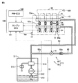
図2は、燃料供給に関するエンジン10および燃料供給装置15の構成を示した図である。本実施の形態は、本発明が適用される車両を、内燃機関として筒内噴射とポート噴射とを併用するデュアル噴射タイプの内燃機関、例えば直列4シリンダのガソリンエンジンを採用するハイブリッド車両としている。
[Configuration for fuel supply]
FIG. 2 is a diagram showing the configuration of the
図2を参照して、エンジン10は、吸気マニホールド36と、スロットル弁37と、吸気ポート21と、シリンダブロックに設けられた4つのシリンダ11とを含む。
Referring to FIG. 2,
吸入空気AIRは、各シリンダ11の吸気工程において、吸気管から吸気マニホールド36および吸気ポート21を通って各シリンダ11に吸入される。
The intake air AIR is sucked into each
各シリンダ11に吸入される空気量(吸入空気量)は、スロットル弁37の開度(スロットル開度θ)によって調節される。スロットル開度θは、エンジンECU141からの制御信号によって制御される。以下の説明では、各シリンダ11に吸入可能な空気量(吸入可能空気量)に対する吸入空気量の比を「エンジン負荷率」と称する。
The amount of air sucked into each cylinder 11 (intake air amount) is adjusted by the opening of the throttle valve 37 (throttle opening θ). The throttle opening θ is controlled by a control signal from the
燃料供給装置15は、低圧燃料供給機構50と、高圧燃料供給機構80とを含む。低圧燃料供給機構50は、燃料圧送部51と、低圧燃料配管52と、低圧デリバリーパイプ53と、低圧燃圧センサ53aと、ポート噴射弁54とを含む。
The
高圧燃料供給機構80は、高圧ポンプ81と、チェック弁82aと、高圧燃料配管82と、高圧デリバリーパイプ83と、高圧燃圧センサ83aと、筒内噴射弁84とを含む。
The high pressure
筒内噴射弁84は、噴孔部84aを各シリンダ11の燃焼室内に露出する筒内噴射用インジェクタである。筒内噴射弁84が開弁動作するとき、高圧デリバリーパイプ83内の加圧された燃料が筒内噴射弁84の噴孔部84aから燃焼室16内に噴射される。
The in-
エンジンECU141は、CPU(Central Processing Unit)、ROM(Read Only Memory)、RAM(Random Access Memory)、入力インターフェース回路、出力インターフェース回路などを含んで構成される。エンジンECU141は、図1のPM−ECUからエンジン起動/停止指令を受けて、エンジン10および燃料供給装置15を制御する。
The
エンジンECU141は、アクセル開度、吸入空気量(スロットル開度θ)、エンジン回転速度、空燃比などに基づいて燃焼毎に必要な燃料噴射量を算出する。また、エンジンECU141は、算出した燃料噴射量に基づいて、ポート噴射弁54および筒内噴射弁84への噴射指令信号などを適時に出力する。
The
なお、本実施の形態においては、低圧燃料供給機構50と高圧燃料供給機構80とを備える場合について説明するが、本発明は高圧燃料供給機構80を備えず低圧燃料供給機構50を備える構成にも適用可能である。
In the present embodiment, the case where the low-pressure
以下、低圧燃料供給機構50についてより詳細に説明する。燃料圧送部51は、燃料タンク511と、フィードポンプ512と、サクションフィルタ513と、燃料フィルタ514と、リリーフ弁515とを含む。
Hereinafter, the low-pressure
燃料タンク511は、エンジン10で消費される燃料、例えばガソリンを貯留する。サクションフィルタ513は、異物の吸入を阻止する。燃料フィルタ514は、吐出燃料中の異物を除去する。
The
リリーフ弁515は、フィードポンプ512から吐出される燃料の圧力が上限圧力に達すると開弁し、燃料の圧力が上限圧力に満たない間は閉弁状態を維持する。
The
低圧燃料配管52は、燃料圧送部51から低圧デリバリーパイプ53までを連結する。ただし、低圧燃料配管52は、燃料パイプに限定されるものではなく、燃料通路が貫通形成される1つの部材や、互いの間に燃料通路が形成される複数の部材であってもよい。
The low-
低圧デリバリーパイプ53は、シリンダ11の直列配置方向の一端側で、低圧燃料配管52に接続される。低圧デリバリーパイプ53には、ポート噴射弁54が連結される。低圧デリバリーパイプ53には、内部の燃料圧力を検出する低圧燃圧センサ53aが装着されている。
The low-
ポート噴射弁54は、噴孔部54aを各シリンダ11に対応する吸気ポート21内に露出するポート噴射用インジェクタである。ポート噴射弁54は、エンジンECU141からの制御信号によって通電されると開弁するニードル弁である。ポート噴射弁54が開弁するとき、フィードポンプ512によって加圧された低圧デリバリーパイプ53内の燃料が噴孔部54aから吸気ポート21内に噴射される。
The
フィードポンプ512は、エンジンECU141から発信される指令信号に基づいて、駆動および停止される。
フィードポンプ512は、燃料タンク511内から燃料を汲み上げ、汲み上げた燃料を加圧して吐出することが可能である。さらに、フィードポンプ512は、エンジンECU141の制御により、単位時間当りの吐出量[m3/sec]や吐出圧[kPa:キロパスカル]を変化させることが可能である。
The
[低圧燃圧センサ53aの故障診断]
フィードポンプ512による燃料の供給圧(以下「燃圧P」ともいう)を可変制御するには、ポート噴射を行なう燃料を貯留する低圧デリバリーパイプ53に設けられた低圧燃圧センサ53aの検出値の信頼性を確保する必要がある。
[Failure diagnosis of low-pressure
In order to variably control the fuel supply pressure (hereinafter also referred to as “fuel pressure P”) by the
このため、本実施の形態によるエンジンECU141は、低圧燃圧センサ53aの故障診断を定期的に行なう。低圧燃圧センサ53aの故障診断においては、エンジンECU141は、燃圧Pをリリーフ弁515の開弁圧に相当する診断圧P2にまで増加させ、燃圧Pを診断圧P2に増加させたことに応じて低圧燃圧センサ53aがリリーフ弁515の開弁圧(診断圧P2)を示す値に変化したか否かに基づいて低圧燃圧センサ53aの故障の有無を判定する。
Therefore,
図3は、低圧燃圧センサ53aが正常である場合における、燃圧P[単位:kPa]と低圧燃圧センサ53aの出力電圧V[単位:V(ボルト)]との対応関係を示す図である。図3に示すように、低圧燃圧センサ53aが正常である場合、燃圧Pが高いほど低圧燃圧センサ53aの出力電圧Vは大きくなる。
FIG. 3 is a diagram showing a correspondence relationship between the fuel pressure P [unit: kPa] and the output voltage V [unit: V (volt)] of the low pressure
通常制御中(低圧燃圧センサ53aの故障診断を行なっていない場合)においては、エンジンECU141は、燃圧Pが通常制御圧P1(たとえば400kPa)となるようにフィードポンプ512を制御する。この際、低圧燃圧センサ53aが正常であれば、低圧燃圧センサ53aの出力電圧Vは通常制御圧P1に対応する電圧V1を示す値となる。
During normal control (when failure diagnosis of the low-pressure
一方、低圧燃圧センサ53aの故障診断を行なう場合、エンジンECU141は、フィードポンプ512の出力を増加させることによって、燃圧Pを通常制御圧P1よりも高い診断圧P2(たとえば650kPa)に増加させる制御(以下「燃圧増加処理」ともいう)を行なう。具体的には、エンジンECU141は、燃圧Pが診断圧P2となるようにフィードポンプ512をフィードフォワード制御する。上述したように、診断圧P2は、リリーフ弁515の開弁圧に相当する燃圧である。
On the other hand, when performing failure diagnosis of the low-pressure
燃圧増加処理中において、低圧燃圧センサ53aが正常であれば、低圧燃圧センサ53aの出力電圧Vは、診断圧P2に対応する電圧V2を示す値となる。そのため、エンジンECU141は、燃圧増加処理を行なったことに応じて低圧燃圧センサ53aの検出値が通常制御圧P1に対応する電圧V1から診断圧P2に対応する電圧V2に変化したか否かに基づいて、低圧燃圧センサ53aの故障の有無を判定する。
If the low pressure
[低圧燃圧センサ53aの故障診断の実行条件]
上述のように、低圧燃圧センサ53aの故障診断中は燃圧Pが増加される。そのため、エンジン10の運転中に低圧燃圧センサ53aの故障診断を行なうと、燃料噴射量が必要以上に多くなりエンジン10の燃焼が悪化することが懸念される。エンジン10の燃焼への影響を回避するためには、エンジン10の停止中(代表的にはモータ走行中)に低圧燃圧センサ53a故障診断を行なうことが想定される。
[Execution Conditions for Failure Diagnosis of Low Pressure
As described above, the fuel pressure P is increased during failure diagnosis of the low-pressure
しかしながら、低圧燃圧センサ53aの故障診断中は、燃圧Pを診断圧P2に維持するためにフィードポンプ512の作動量(回転速度)を通常制御時よりも増加させ続ける必要があるため、フィードポンプ512の作動音(以下「ポンプ音」という)も大きくなる。したがって、エンジン10の停止中に低圧燃圧センサ53aの故障診断を行なうと、エンジン10の作動音(以下「エンジン音」という)がしない状態でポンプ音が大きくなるため、ポンプ音が相対的にユーザに聞こえ易くなりドライバビリティが低下することが懸念される。さらに、燃圧Pを診断圧P2に増加することによって発生するリリーフ弁515の開閉(チャタリング)音もユーザに聞こえ易くなることも懸念される。
However, during the failure diagnosis of the low-pressure
上記のような問題に鑑み、本実施の形態によるエンジンECU141は、エンジン10の停止中であってかつ車速がしきい値V1を超える場合に、低圧燃圧センサ53aの故障診断を行なう。これにより、低圧燃圧センサ53aの故障診断中はエンジン10が停止されているため、燃圧増加処理によって燃圧Pが診断圧P2まで増加されたとしてもエンジン10の燃焼への影響を回避できる。さらに、低圧燃圧センサ53aの故障診断中は車速がしきい値V1を超えており走行ノイズが大きいため、エンジン音がしない状態でポンプ音が大きくなったりリリーフ弁515の開閉音が発生したりしたとしても、ポンプ音およびリリーフ弁の開閉音は相対的にユーザに聞こえ難くなる。その結果、ドライバビリティを低下させることなく低圧燃圧センサ53aの故障診断を行なうことができる。
In view of the above problems, the
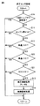
図4は、エンジンECU141が低圧燃圧センサ53aの故障診断を行なう場合の処理手順を示すフローチャートである。このフローチャートは、エンジンECU141の作動中に所定周期で繰り返し実行される。
FIG. 4 is a flowchart showing a processing procedure when
ステップ(以下、ステップを「S」と略す)10にて、エンジンECU141は、今回のトリップ中で既に低圧燃圧センサ53aの故障診断が行なわれているか否かを判定する。なお、トリップとは、1回の走行を表す単位であり、代表的にはユーザが車両システムを起動してから次に車両システムを停止させるまでの期間である。
In step (hereinafter, step is abbreviated as “S”) 10,
今回のトリップ中で既に低圧燃圧センサ53aの故障診断が行なわれている場合(S10にてYES)、エンジンECU141は、以降のS11〜S14の処理を行なわずに、そのまま処理を終了させる。これにより、1回のトリップ中に低圧燃圧センサ53aの故障診断が複数回行なわれることが回避される。つまり、低圧燃圧センサ53aの故障診断は、1回のトリップ中に1回の頻度で行なわれる。
If a fault diagnosis of low-pressure
今回のトリップ中で未だ低圧燃圧センサ53aの故障診断が行なわれてない場合(S10にてNO)、エンジンECU141は、S11にて、エンジン10の停止中であるか否かを判定する。エンジン10の運転中である場合(S11にてNO)、エンジンECU114は、以降のS12〜S14の処理を行なわずに、そのまま処理を終了させる。
If the failure diagnosis of low-pressure
エンジン10の停止中である場合(S11にてYES)、エンジンECU114は、S12にて、車速がしきい値V1を超えるか否かを判定する。しきい値V1は、エンジン10の停止中に燃圧Pを診断圧P2に増加させたとしても、ポンプ音およびリリーフ弁の開閉音は相対的にユーザに聞こえ難くなる程度の走行ノイズが生じる車速である。しきい値V1は、予め実験等によって決められてエンジンECU114のメモリ等に記憶されている。車速がしきい値V1を超えない場合(S12にてNO)、エンジンECU114は、以降のS13、S14の処理を行なわずに、そのまま処理を終了させる。
If
車速がしきい値V1を超える場合(S12にてYES)、エンジンECU114は、S13にて、上述の燃圧増加処理を行なう。すなわち、エンジンECU141は、燃圧Pを通常制御圧P1から診断圧P2に増加させるようにフィードポンプ512をフィードフォワード制御する。
If the vehicle speed exceeds threshold value V1 (YES in S12), engine ECU 114 performs the above-described fuel pressure increase process in S13. That is,
S14にて、エンジンECU141は、低圧燃圧センサ53aの故障診断処理を行なう。この故障診断処理において、エンジンECU141は、低圧燃圧センサ53aの出力が診断圧P2に対応する電圧V2を示す値である場合に低圧燃圧センサ53aが正常であると判定し、そうでない場合に低圧燃圧センサ53aが故障していると判定する。
In S14,
以上のように、本実施の形態によるエンジンECU141は、エンジン10の停止中であってかつ車速がしきい値V1を超える場合(走行ノイズが大きい場合)に、低圧燃圧センサ53aの故障診断を行なう。これにより、エンジン音がしない状態でポンプ音が大きくなったとしても、走行ノイズが大きいため、ポンプ音は相対的にユーザに聞こえ難くなる。その結果、ドライバビリティを低下させることなく低圧燃圧センサ53aの故障診断を行なうことができる。
As described above,
<変形例1>
上述の実施の形態においては、エンジン10の停止中であってかつ車速がしきい値V1を超える場合に、低圧燃圧センサ53aの故障診断を行なう場合について説明した。
<
In the above-described embodiment, the case where the failure diagnosis of the low-pressure
しかしながら、低圧燃圧センサ53aの故障診断中にエンジン10を始動させる必要が生じた場合、燃圧増加処理によって燃圧Pを通常制御圧P1よりも高い診断圧P2に増圧している状態でエンジン10を始動させることになるため、エンジン始動時の燃焼状態が悪化することが懸念される。
However, when the
そこで、本変形例によるエンジンECU114は、エンジン10の停止中であってかつ車速がしきい値V1を超える場合に、車速およびバッテリSOCに基づいて、低圧燃圧センサ53aの故障診断に要する時間よりも長くエンジン10を停止状態に維持できるか否かを判定(予測)する。そして、エンジンECU114は、低圧燃圧センサ53aの故障診断に要する時間よりも長くエンジン10を停止状態に維持できると判定された場合に、低圧燃圧センサ53aの故障診断を行なう。
Therefore, the engine ECU 114 according to the present modified example is longer than the time required for failure diagnosis of the low-pressure
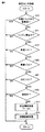
図5は、本変形例によるエンジンECU114が低圧燃圧センサ53aの故障診断を行なう場合の処理手順を示すフローチャートである。なお、図5に示したステップのうち、前述の図4に示したステップと同じ番号を付しているステップについては、既に説明したため詳細な説明はここでは繰り返さない。
FIG. 5 is a flowchart showing a processing procedure when the engine ECU 114 according to the present modification makes a failure diagnosis of the low pressure
エンジン10の停止中であって(S11にてYES)かつ車速がしきい値V1を超える場合(S12にてYES)、エンジンECU114は、S20にて、車速がしきい値V2(V2>V1)未満であるか否かを判定する。この判定は、低圧燃圧センサ53aの故障診断が完了するまでにエンジン10を停止状態に維持可能な車速であることを確認するために行なわれる。
If
車速がしきい値V2を超える場合(S20にてNO)には、要求駆動力が大きくなることが想定され、低圧燃圧センサ53aの故障診断を開始したとしても故障診断が完了するまでにエンジン10を始動させる必要が生じる可能性が高いため、エンジンECU114は、低圧燃圧センサ53aの故障診断を行なわずに処理を終了させる。
If the vehicle speed exceeds threshold value V2 (NO in S20), it is assumed that the required driving force will increase, and even if failure diagnosis of low-pressure
車速がしきい値V2未満である場合(S20にてYES)、エンジンECU114は、S21にて、バッテリSOCがしきい値S1を超えるか否かを判定する。この判定は、低圧燃圧センサ53aの故障診断が完了するまでにモータジェネレータ30に供給可能な電力がバッテリ70に十分に蓄えられていることを確認するために行なわれる。
If the vehicle speed is less than threshold value V2 (YES in S20), engine ECU 114 determines in S21 whether battery SOC exceeds threshold value S1. This determination is performed in order to confirm that the
バッテリSOCがしきい値S1未満である場合(S21にてNO)には、十分な電力がバッテリ70に蓄えられておらず、低圧燃圧センサ53aの故障診断を開始したとしても故障診断が完了するまでにエンジン10を始動させる必要が生じる可能性が高いため、エンジンECU114は、故障診断を行なわずに処理を終了させる。
When battery SOC is less than threshold value S1 (NO in S21), sufficient power is not stored in
バッテリSOCがしきい値S1を超える場合(S21にてYES)、エンジンECU114は、低圧燃圧センサ53aの故障診断に要する時間よりも長くエンジン10を停止状態に維持できると判定し、低圧燃圧センサ53aの故障診断を行なう(S13、S14)。
When battery SOC exceeds threshold value S1 (YES in S21), engine ECU 114 determines that
このように、本変形例によるエンジンECU114は、エンジン10の停止中であってかつ車速がしきい値V1を超える場合であって、かつ車速およびバッテリSOCに基づいてエンジン10を停止状態に維持できると判定された場合に、低圧燃圧センサ53aの故障診断を行なう。そのため、燃圧増加処理によって燃圧Pを診断圧P2に増圧している状態でエンジン10を始動することを回避することができる。
As described above, the engine ECU 114 according to the present modification can maintain the
<変形例2>
上述の変形例1では、車速およびバッテリSOCに基づいて、低圧燃圧センサ53aの故障診断に要する時間よりも長くエンジン10を停止状態に維持できるか否かを判定した。しかしながら、車両1が登坂路を走行するなど車両1の走行ルートによっては、要求駆動力が大きくなりエンジン10を始動させる必要が生じることが懸念される。
<Modification 2>
In the first modification described above, it is determined whether or not the
そこで、車両1が走行ルート情報を検索可能なナビゲーション装置を備える場合には、車速およびバッテリSOCに加えて走行ルート情報に基づいて低圧燃圧センサ53aの故障診断に要する時間よりも長くエンジン10を停止状態に維持できるか否かを判定するようにしてもよい。
Therefore, when the
図6は、本変形例によるエンジンECU114が低圧燃圧センサ53aの故障診断を行なう場合の処理手順を示すフローチャートである。なお、図6に示したステップのうち、前述の図5に示したステップと同じ番号を付しているステップについては、既に説明したため詳細な説明はここでは繰り返さない。
FIG. 6 is a flowchart showing a processing procedure when the engine ECU 114 according to the present modification makes a failure diagnosis of the low pressure
車速がしきい値V2未満であり(S20にてYES)かつバッテリSOCがしきい値S1を超える場合(S21にてYES)、エンジンECU114は、S30にて、ナビゲーション装置からの走行ルート情報に基づいて、低圧燃圧センサ53aの故障診断に要する時間が経過するまでに車両1が登坂路を走行するか否かを判定する。この判定は、低圧燃圧センサ53aの故障診断が完了するまでにエンジン10を停止状態に維持することが困難な道路環境となる可能性があるか否かを確認するために行なわれる。なお、低圧燃圧センサ53aの故障診断に要する時間は、実験等によって予め決めておくことができる。
If vehicle speed is less than threshold value V2 (YES in S20) and battery SOC exceeds threshold value S1 (YES in S21), engine ECU 114 is based on the travel route information from the navigation device in S30. Thus, it is determined whether or not the
低圧燃圧センサ53aの故障診断に要する時間が経過するまでに車両1が登坂路を走行する場合(S30にてYES)には、車両1が登坂路を走行する際に要求駆動力が大きくなりエンジン10を始動させる必要が生じる可能性が高いため、エンジンECU114は、低圧燃圧センサ53aの故障診断を行なわずに処理を終了させる。
When
低圧燃圧センサ53aの故障診断に要する時間が経過するまでに車両1が登坂路を走行しないと判定された場合(S30にてNO)、エンジンECU114は、故障診断に要する時間よりも長くエンジン10を停止状態に維持できると判定し、低圧燃圧センサ53aの故障診断を行なう(S13、S14)。
If it is determined that
このように、本変形例によるエンジンECU114は、車速がしきい値V2未満でかつバッテリSOCがしきい値S1を超えており、かつナビゲーション装置からの走行ルート情報に基づいて車両1が登坂路を走行しないと判定された場合に、エンジン10を停止状態に維持できると判定して、低圧燃圧センサ53aの故障診断を行なう。そのため、燃圧増加処理によって燃圧Pを診断圧P2に増圧している状態でエンジン10を始動することをより適切に抑制することができる。
As described above, the engine ECU 114 according to the present modification has the vehicle speed less than the threshold value V2, the battery SOC exceeds the threshold value S1, and the
今回開示された実施の形態はすべての点で例示であって制限的なものではないと考えられるべきである。本発明の範囲は上記した説明ではなくて特許請求の範囲によって示され、特許請求の範囲と均等の意味および範囲内でのすべての変更が含まれることが意図される。 The embodiment disclosed this time should be considered as illustrative in all points and not restrictive. The scope of the present invention is defined by the terms of the claims, rather than the description above, and is intended to include any modifications within the scope and meaning equivalent to the terms of the claims.
1 車両、10 エンジン、11 シリンダ、15 燃料供給装置、16 回転軸、20,30 モータジェネレータ、21 吸気ポート、36 吸気マニホールド、37 スロットル弁、40 動力分割機構、50 低圧燃料供給機構、51 燃料圧送部、52 低圧燃料配管、53 低圧デリバリーパイプ、53a 低圧燃圧センサ、54 ポート噴射弁、54a,84a 噴孔部、58 リダクション機構、62 駆動輪、70 バッテリ、80 高圧燃料供給機構、81 高圧ポンプ、82 高圧燃料配管、82a チェック弁、83 高圧デリバリーパイプ、83a 高圧燃圧センサ、84 筒内噴射弁、100 制御装置、140 PM−ECU140、141 エンジンECU、142 モータECU、143 バッテリECU、511 燃料タンク、512 フィードポンプ、513 サクションフィルタ、514 燃料フィルタ、515 リリーフ弁。
DESCRIPTION OF
Claims (5)
燃料ポンプと、
前記燃料ポンプから供給された燃料を前記エンジンに噴射する噴射弁と、
前記燃料ポンプによる燃料の供給圧を検出する燃圧センサと、
前記燃料ポンプによる燃料の供給圧を第1燃圧よりも高い第2燃圧に増加させる燃圧増加処理を行ない、前記燃圧増加処理中の前記燃圧センサの検出値に基づいて前記燃圧センサの故障診断を行なう制御装置とを備え、
前記制御装置は、前記エンジンの停止中であってかつ車速がしきい値を超え、かつ前記燃圧センサの故障診断に要する時間よりも長く前記エンジンを停止状態に維持できると判定された場合に、前記燃圧センサの故障診断を行なう、車両。 A vehicle capable of traveling using the power of at least one of an engine and a motor generator,
A fuel pump;
An injection valve for injecting fuel supplied from the fuel pump into the engine;
A fuel pressure sensor for detecting a fuel supply pressure by the fuel pump;
A fuel pressure increase process for increasing the fuel supply pressure by the fuel pump to a second fuel pressure higher than the first fuel pressure is performed, and failure diagnosis of the fuel pressure sensor is performed based on a detection value of the fuel pressure sensor during the fuel pressure increase process A control device,
When it is determined that the engine is stopped, the vehicle speed exceeds a threshold , and the engine can be maintained in a stopped state longer than the time required for failure diagnosis of the fuel pressure sensor , A vehicle that performs failure diagnosis of the fuel pressure sensor.
前記制御装置は、前記蓄電装置の蓄電量が所定量を超える場合に、前記燃圧センサの故障診断に要する時間よりも長く前記エンジンを停止状態に維持できると判定する、請求項1に記載の車両。 The vehicle further includes a power storage device that stores electric power to be supplied to the motor generator,
2. The vehicle according to claim 1 , wherein the control device determines that the engine can be maintained in a stopped state longer than a time required for failure diagnosis of the fuel pressure sensor when a power storage amount of the power storage device exceeds a predetermined amount. .
前記制御装置は、前記蓄電装置の蓄電量が所定量を超える場合であってかつ前記走行ルート情報が登坂路を示す情報でない場合に、前記燃圧センサの故障診断に要する時間よりも長く前記エンジンを停止状態に維持できると判定する、請求項2に記載の車両。 The vehicle further includes a device for searching for travel route information,
When the amount of power stored in the power storage device exceeds a predetermined amount and the travel route information is not information indicating an uphill road, the control device causes the engine to run longer than the time required for failure diagnosis of the fuel pressure sensor. The vehicle according to claim 2, wherein it is determined that the vehicle can be maintained in a stopped state.
前記第2燃圧は、前記燃圧センサの故障診断が行なわれる場合に用いられる診断用燃圧である、請求項1〜3のいずれかに記載の車両。 The first fuel pressure is a control fuel pressure used when failure diagnosis of the fuel pressure sensor is not performed.
The vehicle according to any one of claims 1 to 3 , wherein the second fuel pressure is a diagnostic fuel pressure used when a failure diagnosis of the fuel pressure sensor is performed.
Priority Applications (2)
| Application Number | Priority Date | Filing Date | Title |
|---|---|---|---|
| JP2015063584A JP6217680B2 (en) | 2015-03-26 | 2015-03-26 | vehicle |
| US15/080,854 US10364770B2 (en) | 2015-03-26 | 2016-03-25 | Fuel pressure sensor diagnostic during engine stopping |
Applications Claiming Priority (1)
| Application Number | Priority Date | Filing Date | Title |
|---|---|---|---|
| JP2015063584A JP6217680B2 (en) | 2015-03-26 | 2015-03-26 | vehicle |
Publications (2)
| Publication Number | Publication Date |
|---|---|
| JP2016182862A JP2016182862A (en) | 2016-10-20 |
| JP6217680B2 true JP6217680B2 (en) | 2017-10-25 |
Family
ID=56975000
Family Applications (1)
| Application Number | Title | Priority Date | Filing Date |
|---|---|---|---|
| JP2015063584A Active JP6217680B2 (en) | 2015-03-26 | 2015-03-26 | vehicle |
Country Status (2)
| Country | Link |
|---|---|
| US (1) | US10364770B2 (en) |
| JP (1) | JP6217680B2 (en) |
Families Citing this family (3)
| Publication number | Priority date | Publication date | Assignee | Title |
|---|---|---|---|---|
| JP6439739B2 (en) * | 2016-04-19 | 2018-12-19 | トヨタ自動車株式会社 | Fuel pressure sensor diagnostic device |
| US11607947B2 (en) * | 2019-07-25 | 2023-03-21 | Zhejiang CFMOTO Power Co., Ltd. | Hybrid power train structure in off-road vehicle |
| CN113448318B (en) * | 2021-07-07 | 2022-08-16 | 江铃汽车股份有限公司 | Vehicle offline fault diagnosis control method |
Family Cites Families (24)
| Publication number | Priority date | Publication date | Assignee | Title |
|---|---|---|---|---|
| JP2001107814A (en) | 1999-07-30 | 2001-04-17 | Toyota Motor Corp | Trouble diagnostic device for vaporized fuel purge system |
| JP3956944B2 (en) * | 2004-02-13 | 2007-08-08 | トヨタ自動車株式会社 | Power output apparatus, automobile equipped with the same, and control method therefor |
| JP4192907B2 (en) | 2005-03-11 | 2008-12-10 | トヨタ自動車株式会社 | Auxiliary machine fault diagnosis device for hybrid system |
| JP4508020B2 (en) | 2005-07-13 | 2010-07-21 | トヨタ自動車株式会社 | Diagnostic device for electromagnetic relief valve in fuel supply system |
| JP2010168901A (en) * | 2009-01-20 | 2010-08-05 | Nissan Motor Co Ltd | High pressure fuel pump |
| JP2010208576A (en) * | 2009-03-12 | 2010-09-24 | Toyota Motor Corp | Failure detection device of hybrid vehicle |
| JP4816767B2 (en) * | 2009-06-08 | 2011-11-16 | トヨタ自動車株式会社 | Vehicle control device |
| WO2011007772A1 (en) | 2009-07-15 | 2011-01-20 | ボッシュ株式会社 | Method for diagnosing error of pressure sensor and common rail type fuel injection control device |
| US8192324B2 (en) * | 2009-11-13 | 2012-06-05 | Ford Global Technologies, Llc | Vehicle and method for controlling engine start in a vehicle |
| JP2011163220A (en) | 2010-02-10 | 2011-08-25 | Denso Corp | Control device for fuel supply system |
| JP2011185158A (en) | 2010-03-09 | 2011-09-22 | Denso Corp | Failure diagnostic device of high pressure fuel supply system of internal combustion engine |
| US8543272B2 (en) * | 2010-08-05 | 2013-09-24 | Ford Global Technologies, Llc | Distance oriented energy management strategy for a hybrid electric vehicle |
| JP5163810B2 (en) | 2010-10-19 | 2013-03-13 | トヨタ自動車株式会社 | Leak mechanism diagnostic device for internal combustion engine |
| JP5780897B2 (en) * | 2011-09-21 | 2015-09-16 | 日立オートモティブシステムズ株式会社 | Control device for internal combustion engine |
| JP5973710B2 (en) * | 2011-11-22 | 2016-08-23 | 日産自動車株式会社 | Control device for hybrid vehicle |
| JP2013238202A (en) | 2012-05-17 | 2013-11-28 | Toyota Motor Corp | Abnormality determination device for pressure sensor |
| JP5991192B2 (en) * | 2012-12-21 | 2016-09-14 | トヨタ自動車株式会社 | Control device for hybrid vehicle |
| US9394845B2 (en) * | 2013-12-10 | 2016-07-19 | Fca Us Llc | Fuel rail pressure sensor diagnostic techniques |
| US9327706B2 (en) * | 2014-02-04 | 2016-05-03 | Ford Global Technologies, Llc | Systems and methods for improving engine starting |
| JP6331861B2 (en) * | 2014-08-08 | 2018-05-30 | トヨタ自動車株式会社 | Control device for internal combustion engine |
| JP6149833B2 (en) * | 2014-09-12 | 2017-06-21 | トヨタ自動車株式会社 | Control device for internal combustion engine |
| JP6292143B2 (en) * | 2015-02-10 | 2018-03-14 | トヨタ自動車株式会社 | vehicle |
| KR101877299B1 (en) * | 2016-04-07 | 2018-07-11 | (주)모토닉 | Control apparatus and method of flow control valve for high pressure fuel pump |
| JP6439739B2 (en) * | 2016-04-19 | 2018-12-19 | トヨタ自動車株式会社 | Fuel pressure sensor diagnostic device |
-
2015
- 2015-03-26 JP JP2015063584A patent/JP6217680B2/en active Active
-
2016
- 2016-03-25 US US15/080,854 patent/US10364770B2/en not_active Expired - Fee Related
Also Published As
| Publication number | Publication date |
|---|---|
| US10364770B2 (en) | 2019-07-30 |
| US20160281628A1 (en) | 2016-09-29 |
| JP2016182862A (en) | 2016-10-20 |
Similar Documents
| Publication | Publication Date | Title |
|---|---|---|
| US9957910B2 (en) | Diagnostic system and diagnostic method for internal combustion engine | |
| JP5505509B2 (en) | Power train, control method and control apparatus for internal combustion engine | |
| JP6332656B2 (en) | Vehicle with internal combustion engine | |
| JP5610158B2 (en) | Hybrid vehicle | |
| JP6217680B2 (en) | vehicle | |
| JP6292143B2 (en) | vehicle | |
| JP2014092066A (en) | EGR valve fault detection device | |
| JP6197828B2 (en) | Vehicle control device | |
| JP2016003572A (en) | Vehicular fuel control device and vehicular fuel control method | |
| JP6156418B2 (en) | Vehicle control device | |
| JP2016185764A (en) | Hybrid vehicle | |
| JP6511889B2 (en) | Control device for internal combustion engine | |
| JP6308111B2 (en) | Vehicle control device | |
| US10589737B2 (en) | Method and device for controlling mild hybrid vehicle | |
| JP2008111402A (en) | Engine control unit | |
| JP6344295B2 (en) | Hybrid vehicle | |
| JP6160600B2 (en) | Vehicle control device | |
| US20190126909A1 (en) | Method and device for controlling mild hybrid electric vehicle | |
| JP5605713B2 (en) | Control device and control method for internal combustion engine | |
| JP5978760B2 (en) | Exhaust gas purification method and apparatus for internal combustion engine | |
| JP2010203346A (en) | Control device for internal combustion engine | |
| US20180080393A1 (en) | Control device applied to hybrid vehicle | |
| JP2023178738A (en) | Control device of hybrid vehicle | |
| KR20180068213A (en) | Method and device for controlling mild hybrid electric vehicle | |
| JP2019132185A (en) | Controller of internal combustion engine |
Legal Events
| Date | Code | Title | Description |
|---|---|---|---|
| A621 | Written request for application examination |
Free format text: JAPANESE INTERMEDIATE CODE: A621 Effective date: 20160824 |
|
| A977 | Report on retrieval |
Free format text: JAPANESE INTERMEDIATE CODE: A971007 Effective date: 20170518 |
|
| A131 | Notification of reasons for refusal |
Free format text: JAPANESE INTERMEDIATE CODE: A131 Effective date: 20170530 |
|
| A521 | Written amendment |
Free format text: JAPANESE INTERMEDIATE CODE: A523 Effective date: 20170714 |
|
| TRDD | Decision of grant or rejection written | ||
| A01 | Written decision to grant a patent or to grant a registration (utility model) |
Free format text: JAPANESE INTERMEDIATE CODE: A01 Effective date: 20170829 |
|
| A61 | First payment of annual fees (during grant procedure) |
Free format text: JAPANESE INTERMEDIATE CODE: A61 Effective date: 20170911 |
|
| R151 | Written notification of patent or utility model registration |
Ref document number: 6217680 Country of ref document: JP Free format text: JAPANESE INTERMEDIATE CODE: R151 |