JP6214325B2 - Container supply apparatus and container supply method - Google Patents
Container supply apparatus and container supply method Download PDFInfo
- Publication number
- JP6214325B2 JP6214325B2 JP2013216276A JP2013216276A JP6214325B2 JP 6214325 B2 JP6214325 B2 JP 6214325B2 JP 2013216276 A JP2013216276 A JP 2013216276A JP 2013216276 A JP2013216276 A JP 2013216276A JP 6214325 B2 JP6214325 B2 JP 6214325B2
- Authority
- JP
- Japan
- Prior art keywords
- container
- paper cup
- opening
- supply device
- path
- Prior art date
- Legal status (The legal status is an assumption and is not a legal conclusion. Google has not performed a legal analysis and makes no representation as to the accuracy of the status listed.)
- Active
Links
Images


Description
本発明は、例えば即席食品等の食品を容器内に自動的に充填するための食品充填装置に、多数の容器を順次供給する容器供給装置及び容器供給方法に関するものである。 The present invention relates to a container supply apparatus and a container supply method for sequentially supplying a large number of containers to a food filling apparatus for automatically filling a container with food such as instant food.
この種の装置としては、例えば特許文献1に開示されているように、可動ストッパを用いて、ホルダの内部に積み重ねられた複数のフランジ付カップ状容器のフランジへの支えを制御することで、最下位の容器から順次1つずつ分離し、ホルダから取り出すものが知られている。 As this type of device, for example, as disclosed in Patent Document 1, by using a movable stopper, by controlling the support to the flange of a plurality of flanged cup-shaped containers stacked inside the holder, What isolate | separates one by one from the lowest container one by one, and takes out from a holder is known.
しかしながら上記従来の容器供給装置は、カップ状容器のフランジへの支えを制御することで取り出すものであり、フランジ付の容器を用いることを前提としていた。そのため、フランジを有さない容器には適用できないという問題があった。 However, the above-described conventional container supply device is taken out by controlling the support of the cup-shaped container on the flange, and is based on the assumption that a container with a flange is used. Therefore, there was a problem that it cannot be applied to a container having no flange.
本発明は、このような課題に鑑みなされたもので、積み重ねられた複数の容器を、フランジの有無に関わらず、順次1つずつ分離して取り出すことができる容器供給装置及び容器供給方法を提供することを目的とする。 The present invention has been made in view of such a problem, and provides a container supply device and a container supply method capable of sequentially separating and taking out a plurality of stacked containers one by one regardless of the presence or absence of a flange. The purpose is to do.
上記目的を達成するために、本発明に係る容器供給装置は、積み重ねられた複数の容器を開口部方向から排出する容器供給装置であって、開口部方向先端の第一容器の開口部方向への進路を遮断または開放する第一支持部と、前記第一容器に隣接した第二容器を支持または開放する第二支持部と、を備えることを特徴とする。 In order to achieve the above object, a container supply device according to the present invention is a container supply device that discharges a plurality of stacked containers from the opening direction, and is directed toward the opening of the first container at the tip in the opening direction. And a second support portion for supporting or opening a second container adjacent to the first container.
また、本発明に係る容器供給方法は、積み重ねられた複数の容器を開口部方向から排出する容器供給方法であって、開口部方向先端の第一容器の進路を遮断したまま当該第一容器に隣接した第二容器を支持するステップと、前記第二容器を支持したまま前記第一容器の開口部方向への進路を開放することで前記第一容器を排出可能とするステップと、からなることを特徴とする。 Further, the container supply method according to the present invention is a container supply method for discharging a plurality of stacked containers from the direction of the opening, and the first container is closed while the path of the first container at the tip of the opening is blocked. Supporting the adjacent second container, and allowing the first container to be discharged by opening a path toward the opening of the first container while supporting the second container. It is characterized by.
本発明によれば、積み重ねられた複数の容器を、フランジの有無によらずに順次1つずつ分離して取り出すことができる。 According to the present invention, a plurality of stacked containers can be separated and taken out one by one without depending on the presence or absence of a flange.
以下、本発明の実施形態に係る容器供給装置および容器供給方法について、図面に基づいて詳細に説明する。 Hereinafter, a container supply device and a container supply method according to embodiments of the present invention will be described in detail based on the drawings.
図1は本発明を適用した容器供給装置の一実施形態の構成として紙カップ供給装置1の実施概要を示したものである。詳細は後述するが、第一支持部3、第二支持部2、及び紙カップ取り出し部4の連動により、紙カップ100が紙カップ取り出し部4の吸着部41に吸着されて取り出される。取り出された紙カップ100は、紙カップ取り出し部4と連結した上下可動部5が固定筒部6に沿って下方へスライドすることにより下方に移動される。紙カップ取り出し部4が回転軸43を軸として約180°回転することにより、紙カップ100は反転する。紙カップ取り出し部4の吸着部41による吸着が解除され、紙カップ100は、搬送路7上を左方向に流れる紙カップ搬送用バケット8に入れられ、次工程へと順次搬送される。
FIG. 1 shows an outline of an implementation of a paper cup supply device 1 as a configuration of an embodiment of a container supply device to which the present invention is applied. Although details will be described later, the
図2(a)〜(c)は、本実施形態に係る紙カップ供給装置1で使用される紙カップ100の一例を示したものである。紙カップ100は、例えば切り出した板紙等を折り曲げて接着剤等で糊付けされることで作成される。このような紙カップ100は、外力が加えられることで容易に変形し、変形状態の個体差が大きいという特徴がある。
2A to 2C show an example of a
図2(a)は、紙カップ100の正面図である。開口部である下方ほど径が大きい形状をとっている。図示例では正面からは略台形形状と視認されるが、このような形状に限定されず、側面が湾曲していたり、側面の一部で傾斜角度が変化していたりしても良い。
FIG. 2A is a front view of the
図2(b)は、紙カップ100の平面図である。紙カップ100の底面が略四角形であるのに対し、開口部の各辺はやや外側に膨らんだ形状をしている。これは、紙カップ100の剛性が低いため、成形時の折り曲げに対して元の板紙等の形状に戻ろうとする力が紙カップ100の変形として現れたものと考えられる。
FIG. 2B is a plan view of the
なお、紙カップ100の素材をより剛性の高いものとしたり、成形方法を工夫したりすることによって、開口部の形状をより四角形に近づけることも可能であるが、このような紙カップ100を用いてもよい。また、底面や開口部の形状は四角形に限定されず、他の多角形や円形でもよく、また底面と開口部の形状が同一である必要もない。
The shape of the opening can be made closer to a quadrangle by making the material of the
図2(c)は、紙カップ100のA−A線断面図である。ここで、紙カップ100の厚みは十分に小さいため、厚みを表現せず線図のみで示している。図2(c)に示す通り、開口部にフランジ等は設けられておらず、板紙等が切りだされた断面がむき出しとなっている。
FIG. 2C is a cross-sectional view of the
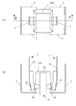
図3(a)、(b)は、それぞれ紙カップ供給装置1の平面図及び正面図である。また、図4(a)、(b)は、紙カップ供給装置1に紙カップ100を載置した場合の平面図及び正面図である。なお、図4(b)の正面図においては、説明のため、紙カップ100をB−B線断面図として示している。
3A and 3B are a plan view and a front view of the paper cup supply device 1, respectively. FIGS. 4A and 4B are a plan view and a front view when the
第一支持部3は、左右に1ずつ対向して設けられ、図3(b)、図4(b)に示す通り、正面図では左がL字型、右が逆L字型の形状をなす。また、図3(a)、図4(a)に示す通り、平面図では中央部がくり貫かれた形状をなし、当該中央部に第二支持部2及び紙カップ取り出し部4が位置している。紙カップ100が載置された場合には、図4(a)に示す通り、第一支持部3により紙カップ100の開口部方向への進路が遮られる。
The
第一支持部3は、平面図及び正面図上、左右方向に移動制御可能であり、各第一支持部3が連動して互いに反対方向に移動制御可能であることが望ましい。また、第一支持部3は、紙カップ100が複数積み重ねられて載置された場合にその荷重に耐えられる程度の強度を有しており、例えば金属等で構成される。
It is desirable that the
第二支持部2は、左右に1ずつ対向して設けられ、それぞれフレーム21と紙カップ当接部22とからなる。フレーム21は板状である程度の剛性を有する素材からなり、例えば金属等で構成される。紙カップ当接部22は摩擦力が大きく紙カップ100に直接触れても傷つけない程度の柔軟性をもつことが望ましく、例えばゴム等で構成される。また、第二支持部2は、正面図上、下方で内側に屈曲していることが望ましい。
The
第二支持部2は、平面図及び正面図上、左右方向に移動制御可能であり、各第二支持部2が連動して互いに反対方向に移動制御可能であることが望ましい。紙カップ100が載置された状態で各第二支持部2が内側に移動制御された場合、図4(a)に示す通り、紙カップ100を左右から押圧し、紙カップ100を変形させることが可能である。
It is desirable that the
紙カップ取り出し部4は、左右に吸着部41、正面図における上部に押し上げ部42を備える。紙カップ取り出し部4は、正面図上、上下に移動制御可能である。吸着部41は当接面に密着可能なよう、ゴム等の柔らかい素材からなり、内部に空気が通るための孔が設けられている。図4(b)に示すように、例えば紙カップ100の内面が吸着部41に密着すると、吸着部41は内部の孔を通して空気を吸引することで、紙カップ100を吸着することが可能である。空気の吸引は、吸引部41や紙カップ取り出し部4本体を介して外部の装置から行うものとしてもよい。押し上げ部42は、図4(b)に示す通り、紙カップ100の底面に当接して紙カップ100を押し上げることが可能である。押し上げ部42は、紙カップ100の底面を傷つけないよう柔らかい素材であることが望ましく、例えばゴム等で構成される。
The paper cup take-out
紙カップ100は、第二支持部2により押圧されると、図4(a)に示す通り、押圧された側面は凹み、他方の側面はより膨らんだ形状をなす。
When the
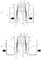
<動作例>
図5〜図8は、紙カップ供給装置1の動作例を示す正面図であり、時系列に沿って図示している。なお、説明のため、図4(b)と同様、紙カップ100をB−B線断面図で示している。
<Operation example>
5-8 is a front view which shows the operation example of the paper cup supply apparatus 1, and has shown in figure along the time series. For the sake of explanation, the
図5(a)に示す通り、紙カップ供給装置1に複数の紙カップ100が開口部を下方に向けて積み重ねられている。第一支持部3は紙カップ100の進路を遮る程度に互いに接近しており、第二支持部2は紙カップ100とは接していない状態である。以下、紙カップ100のうち、最下位すなわち取り出し方向先端に位置するものを第一紙カップ101、第一紙カップ101に隣接し、取り出し方向二番目に位置するものを第二紙カップ102と呼ぶ。
As shown in FIG. 5A, a plurality of
図5(b)に示す通り、紙カップ取り出し部4が上方に移動制御され、押し上げ部42により第一紙カップ101が押し上げられる。すると、第一紙カップ101の上方に積み重ねられた他の紙カップ100も同じく押し上げられる。これにより、第一紙カップ101の開口部が第一支持部3と接していないので、後述する第二支持部2による紙カップ100の挟み込みが行われても、第一支持部3との摩擦によって第一紙カップ101の開口部が傷つく恐れがない。
As shown in FIG. 5B, the paper cup take-out
図6(a)に示す通り、第二支持部2が互いに内側方向に移動し、紙カップ100を左右から挟み込んで押圧する。これにより、第一紙カップ101及び第二紙カップ102を含む複数の紙カップ100が、図4(a)で示した例と同様に、左右方向の側面が凹んだ形状をなす。このとき、複数の紙カップ100のうち、第一紙カップ101の開口部は紙カップ当接部22より下方に突出して下方への進路が遮られてはいないが、第二紙カップ102の開口部は、紙カップ当接部22と当接することで下方への進路が遮られている。また、第二支持部2による押圧により、第一紙カップ101は吸着部41と密着している。
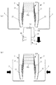
図6(b)に示す通り、第一支持部3がそれぞれ外側に移動し、第一紙カップ101の取り出し方向への進路を開放する。
As shown in FIG. 6A, the
As shown in FIG. 6 (b), the
図7(a)に示す通り、吸着部41による吸着が行われつつ、紙カップ取り出し部4が下方へ移動される。吸着部41による吸着により第一紙カップ101と吸着部41とが密着しており、また、第一紙カップ101は紙カップ当接部22により下方への進路が遮られていないのに対して第二紙カップ102は紙カップ当接部22により下方への進路が遮られているので、紙カップ100のうち第一紙カップ101のみが他の紙カップ100から分離されて、紙カップ取り出し部4と一体的に下方へ移動される。なお、吸着部41による吸着は、図5(a)から図7(a) のどのタイミングで開始されていてもよい。
As shown in FIG. 7A, the paper cup take-out
図7(b)に示す通り、紙カップ取り出し部4により第一紙カップ101が取り出されると、第一支持部3がそれぞれ内側に移動し、第二紙カップ102の取り出し方向への進路を遮断する。
As shown in FIG. 7B, when the
図8に示す通り、第二支持部2がそれぞれ外側に移動し、第二紙カップ102を含む複数の紙カップ100が第二支持部2から開放されて落下し、第二紙カップ102が第一支持部3と当接した位置で停止する。図7(b)から図8の何れかのタイミングで、図1に示す通り、紙カップ取り出し部4が第一紙カップ101とともに回転軸43を軸として180°回転し、搬送路7上の紙カップ搬送用バケット8に第一紙カップ101を載置するように吸着部41の吸着を解除する。
As shown in FIG. 8, the
その後、紙カップ取り出し部4が再度180°回転し、上方に移動することで図5(a)の状態に戻り、以降同様の動作を繰り返すことで順次1ずつ紙カップ100を取り出すことが可能となる。
Thereafter, the paper cup take-out
なお、本願発明は、前記実施形態に限定されるものではなく、実施段階ではその要旨を逸脱しない範囲で種々に変形することが可能である。さらに、前記実施形態には種々の段階の発明が含まれており、開示される複数の構成要件における適宜な組み合わせにより種々の発明が抽出され得る。例えば、実施形態に示される全構成要件から幾つかの構成要件が削除されたり、幾つかの構成要件が異なる形態にして組み合わされても、発明が解決しようとする課題の欄で述べた課題が解決でき、発明の効果の欄で述べられている効果が得られる場合には、この構成要件が削除されたり組み合わされた構成が発明として抽出され得るものである。 Note that the present invention is not limited to the above-described embodiment, and various modifications can be made without departing from the scope of the invention in the implementation stage. Further, the embodiments include inventions at various stages, and various inventions can be extracted by appropriately combining a plurality of disclosed constituent elements. For example, even if some constituent requirements are deleted from all the constituent requirements shown in the embodiment or some constituent requirements are combined in different forms, the problems described in the column of the problem to be solved by the invention are not solved. When the effects described in the column “Effects of the Invention” can be obtained, a configuration in which these constituent requirements are deleted or combined can be extracted as an invention.
例えば、紙カップ100は、厚みがより厚くても薄くても良い。また、剛性がより高くても低くてもいい。第二支持部2に押圧されることである程度の形状変形があり、吸着部41に押し付けられる構成であれば良い。また、紙カップ100の代わりに紙以外の容器、例えばプラスチック容器等を用いても良い。
For example, the
また、紙カップ100を開口部を下方に向けて積み重ねる必要はなく、例えば開口部を上方に向けて積み重ねても良い。この場合、容器供給装置1は上下逆の構成となり、紙カップ100を下部で支える新たな支持部が必要になるが、第一支持部3の構成は必ずしも必要ではなくなる。
Further, it is not necessary to stack the
また、押し上げ部42は紙カップ取り出し部4と一体である必要はなく、第一紙カップ101を押し上げる機能が果たせれば、別個の構成としてもよい。もちろん、押し上げ部42による押し上げ工程を実施形態から除外してもよい。
Further, the push-up
また、第一紙カップ101の取り出しは、吸着部41の吸着によるものに限定されない。例えば、粘着性のある部材を第一紙カップ101に当接することで取り出してもよいし、その他公知の方法を用いてもよい。さらに、紙カップ取り出し部4を構成から除外し、第二支持部2による押圧力を、第二紙カップ102を支持するのには足りるが第一紙カップを支持するには足りない程度の押圧力とすることで、図6(a)に相当する第二支持部2による押圧時には第一紙カップ101は第一支持部3に接地し、図6(b)に相当する第一支持部3の外側方向への移動時に第一紙カップ101が落下することで取り出す構成としてもよい。
Further, the removal of the
1 紙カップ供給装置
2 第二支持部
21 フレーム
22 紙カップ当接部
3 第一支持部
4 紙カップ取り出し部
41 吸着部
42 押し上げ部
43 回転軸
5 上下可動部
6 固定筒部
7 搬送路
8 紙カップ搬送用バケット
100 紙カップ
101 第一紙カップ
102 第二紙カップ
DESCRIPTION OF SYMBOLS 1 Paper
Claims (7)
開口部方向先端の第一容器の開口部方向への進路を遮断または開放する第一支持部と、
前記第一容器に隣接した第二容器を支持または開放する第二支持部と、
前記第一容器を上方に押し上げる押し上げ部と、
を備える容器供給装置。 A container supply device for discharging a plurality of stacked containers from the opening direction,
A first support portion that blocks or opens a path in the direction of the opening of the first container at the tip of the opening,
A second support for supporting or opening a second container adjacent to the first container;
A push-up portion that pushes the first container upward;
A container supply device comprising:
前記第二支持部は、前記第一容器の外側側面を押圧することが可能であり、
前記第二支持部による前記第一容器の外側側面の押圧により、前記吸着部による前記第一容器の吸着を補助する請求項1ないし請求項3何れか一項に記載の容器供給装置。 A container take-out part having an adsorbing part capable of adsorbing the inner side surface of the first container;
The second support part can press the outer side surface of the first container,
The container supply device according to any one of claims 1 to 3, wherein the suction of the first container by the suction part is assisted by pressing of the outer side surface of the first container by the second support part.
ないし請求項4に記載の容器供給装置。 Before SL plurality of containers, according to claim 1, characterized in that are stacked openings as lower
The container supply apparatus of Claim 4 thru | or 4.
第二容器を支持することを特徴とする請求項5に記載の容器供給装置。 The container supply device according to claim 5, wherein the second support part supports the second container while the first container is pushed up by the push-up part.
開口部方向先端の第一容器の進路を遮断するステップと、
前記第一容器を上方に押し上げるステップと、
前記第一容器の進路を遮断したまま前記第一容器に隣接した第二容器を支持するステップと、
前記第二容器を支持したまま前記第一容器の開口部方向への進路を開放することで前記
第一容器を排出可能とするステップと、
からなる容器供給方法。 A container supply method for discharging a plurality of stacked containers from the opening direction,
A step you block the first container path of opening direction leading end,
Pushing the first container upward;
Supporting a second container adjacent to the first container while blocking a path of the first container;
Allowing the first container to be discharged by opening a path toward the opening of the first container while supporting the second container;
A container supply method comprising:
Priority Applications (1)
| Application Number | Priority Date | Filing Date | Title |
|---|---|---|---|
| JP2013216276A JP6214325B2 (en) | 2013-10-17 | 2013-10-17 | Container supply apparatus and container supply method |
Applications Claiming Priority (1)
| Application Number | Priority Date | Filing Date | Title |
|---|---|---|---|
| JP2013216276A JP6214325B2 (en) | 2013-10-17 | 2013-10-17 | Container supply apparatus and container supply method |
Related Child Applications (1)
| Application Number | Title | Priority Date | Filing Date |
|---|---|---|---|
| JP2017178579A Division JP6552568B2 (en) | 2017-09-19 | 2017-09-19 | Container supply apparatus and container supply method |
Publications (2)
| Publication Number | Publication Date |
|---|---|
| JP2015077995A JP2015077995A (en) | 2015-04-23 |
| JP6214325B2 true JP6214325B2 (en) | 2017-10-18 |
Family
ID=53009822
Family Applications (1)
| Application Number | Title | Priority Date | Filing Date |
|---|---|---|---|
| JP2013216276A Active JP6214325B2 (en) | 2013-10-17 | 2013-10-17 | Container supply apparatus and container supply method |
Country Status (1)
| Country | Link |
|---|---|
| JP (1) | JP6214325B2 (en) |
Families Citing this family (2)
| Publication number | Priority date | Publication date | Assignee | Title |
|---|---|---|---|---|
| JP6722840B2 (en) | 2017-07-21 | 2020-07-15 | 株式会社安川電機 | Container supply device, container supply method, and container mounting system |
| CN114132560B (en) * | 2021-12-02 | 2023-04-18 | 安徽创欣环保科技有限公司 | Transfer device for processing disposable paper cup |
Family Cites Families (4)
| Publication number | Priority date | Publication date | Assignee | Title |
|---|---|---|---|---|
| JPS4914905B1 (en) * | 1970-08-28 | 1974-04-11 | ||
| JPS535588Y2 (en) * | 1972-05-22 | 1978-02-13 | ||
| JPS6029035Y2 (en) * | 1981-07-23 | 1985-09-03 | 伊藤 禎美 | Conical container separation device |
| JPH10194241A (en) * | 1996-12-27 | 1998-07-28 | Sunrise Syst:Kk | Automatic feeder of container |
-
2013
- 2013-10-17 JP JP2013216276A patent/JP6214325B2/en active Active
Also Published As
| Publication number | Publication date |
|---|---|
| JP2015077995A (en) | 2015-04-23 |
Similar Documents
| Publication | Publication Date | Title |
|---|---|---|
| JP4927979B2 (en) | Semiconductor die pick-up device and semiconductor die pick-up method using the device | |
| JP6145891B2 (en) | Method and apparatus for automatic removal of package contents | |
| KR102235381B1 (en) | Method and device for fitting reinforcements on a cardboard packaging cutout,and corresponding packaging | |
| CN102308377A (en) | Apparatus and method for picking up semiconductor die | |
| JP6151322B2 (en) | Box making equipment | |
| JP6214325B2 (en) | Container supply apparatus and container supply method | |
| ES2839574T3 (en) | Molding tool and procedure to manufacture a container | |
| JP5866097B2 (en) | Suction tool and picking device | |
| TWI588928B (en) | Die pick-up method | |
| US10138078B2 (en) | De-stacking device for de-stacking layers of transport pallets with or without intermediary layers | |
| JP6924601B2 (en) | Sheet material supply device and sheet material supply method | |
| JP6552568B2 (en) | Container supply apparatus and container supply method | |
| JP6867865B2 (en) | Container removal device | |
| JP6179044B2 (en) | Fixed state determination device and container assembly facility | |
| JP6401099B2 (en) | Container take-out device | |
| TWI579951B (en) | Turn-over device of semiconductor element and testing apparatus thereof | |
| JP6027398B2 (en) | Sheet insertion device and sheet insertion method | |
| JP5808642B2 (en) | Box making equipment | |
| JP6812154B2 (en) | Packaging material take-out device | |
| JP6836112B2 (en) | Sheet paper lifting device and sheet sheet lifting method | |
| JP2016182976A (en) | Box packing device and box packing method | |
| JP4640059B2 (en) | Sheet substrate supply device | |
| JP5188552B2 (en) | Drug dispensing device | |
| JP6207079B2 (en) | Method and apparatus for separating and transporting stacked trays | |
| JP2014011184A (en) | Chip transporting system and chip tray |
Legal Events
| Date | Code | Title | Description |
|---|---|---|---|
| A621 | Written request for application examination |
Free format text: JAPANESE INTERMEDIATE CODE: A621 Effective date: 20160704 |
|
| A977 | Report on retrieval |
Free format text: JAPANESE INTERMEDIATE CODE: A971007 Effective date: 20170525 |
|
| A131 | Notification of reasons for refusal |
Free format text: JAPANESE INTERMEDIATE CODE: A131 Effective date: 20170530 |
|
| A521 | Request for written amendment filed |
Free format text: JAPANESE INTERMEDIATE CODE: A523 Effective date: 20170711 |
|
| TRDD | Decision of grant or rejection written | ||
| A01 | Written decision to grant a patent or to grant a registration (utility model) |
Free format text: JAPANESE INTERMEDIATE CODE: A01 Effective date: 20170905 |
|
| A61 | First payment of annual fees (during grant procedure) |
Free format text: JAPANESE INTERMEDIATE CODE: A61 Effective date: 20170919 |
|
| R150 | Certificate of patent or registration of utility model |
Ref document number: 6214325 Country of ref document: JP Free format text: JAPANESE INTERMEDIATE CODE: R150 |
|
| R250 | Receipt of annual fees |
Free format text: JAPANESE INTERMEDIATE CODE: R250 |
|
| R250 | Receipt of annual fees |
Free format text: JAPANESE INTERMEDIATE CODE: R250 |
|
| R250 | Receipt of annual fees |
Free format text: JAPANESE INTERMEDIATE CODE: R250 |
|
| R250 | Receipt of annual fees |
Free format text: JAPANESE INTERMEDIATE CODE: R250 |