JP6213889B2 - Faucet fittings - Google Patents
Faucet fittings Download PDFInfo
- Publication number
- JP6213889B2 JP6213889B2 JP2013081577A JP2013081577A JP6213889B2 JP 6213889 B2 JP6213889 B2 JP 6213889B2 JP 2013081577 A JP2013081577 A JP 2013081577A JP 2013081577 A JP2013081577 A JP 2013081577A JP 6213889 B2 JP6213889 B2 JP 6213889B2
- Authority
- JP
- Japan
- Prior art keywords
- amorphous carbon
- carbon layer
- layer
- film thickness
- intermediate layer
- Prior art date
- Legal status (The legal status is an assumption and is not a legal conclusion. Google has not performed a legal analysis and makes no representation as to the accuracy of the status listed.)
- Expired - Fee Related
Links
Images

Landscapes
- Domestic Plumbing Installations (AREA)
Description
本発明は、水栓金具の表面処理に関し、さらに詳しくは、防汚性の機能付与を目的とし、表面にアモルファスカーボン膜を形成した水栓金具に関する。 The present invention relates to a surface treatment of a faucet fitting, and more particularly, to a faucet fitting having an amorphous carbon film formed on the surface for the purpose of imparting an antifouling function.
水栓金具は、製品としての意匠性を高める目的で、材質表面に対して機械加工やめっきが施されている。 The faucet fitting is machined or plated on the material surface for the purpose of enhancing the design as a product.
浴室や洗面台で使用される水栓金具は、水道水や洗剤等が表面に付着する環境下で使用される。水栓金具の表面に付着した水や汚れは、それらが乾燥することによって製品表面に汚れとして固着する。これらの汚れは、水栓金具の外観を損ない商品価値を下げるだけでなく、使用者に対して清掃作業という煩わしさを与えるという懸念がある。 Faucet fittings used in bathrooms and washstands are used in an environment where tap water, detergent, etc. adhere to the surface. The water and dirt adhering to the surface of the faucet fitting adhere to the product surface as they become dry. These stains not only impair the appearance of the faucet fitting and lower the product value, but also have the concern of giving the user troublesome cleaning work.
水栓金具の表面において想定される汚れの種類には、油分、金属石鹸、洗剤残り等の有機成分の汚れと、水道水中に溶解しているシリカや炭酸カルシウム等の水垢等の無機成分による汚れがある。有機成分の汚れは、洗剤によって比較的容易に除去することが可能である。一方、無機成分の汚れは、製品表面に強固に固着するため、中性洗剤等で除去することが難しい。固着した水垢を清掃により除去する手段として、例えば水垢専用の研磨粒子入りのスポンジや洗剤が市販されている。しかしながら、研磨粒子自体や過度な清掃行為によって、水周り製品の表面に損傷を与え、結果として傷などが発生し外観を損ねる場合があり、抜本的な解決には至っていない。 The types of dirt assumed on the surface of faucet fittings include dirt from organic components such as oil, metal soap and detergent residue, and dirt from inorganic components such as silica and calcium carbonate dissolved in tap water. There is. Organic component stains can be removed relatively easily by detergents. On the other hand, since the inorganic component is firmly adhered to the product surface, it is difficult to remove it with a neutral detergent or the like. As means for removing the adhered scale by cleaning, for example, sponges and detergents containing abrasive particles exclusively for scale are commercially available. However, the abrasive particles themselves and excessive cleaning action may damage the surface of the product around the water, resulting in scratches and the like, which may impair the appearance and have not led to a radical solution.
無機汚れに対する対策として、特許文献1(特開2000−72488)には、ガラス基材上にシリコンを主成分とする層、アモルファスカーボン層を順次形成することにより、無機汚れがつきにくい、または落としやすくなることが開示されている。また、ガラス基材とアモルファスカーボン層の密着性を向上させるために、シリコンを主成分とする層を0.5〜3nmの膜厚とし、アモルファスカーボン層は、防汚機能発現のため、3nm〜50nmの膜厚とすることが開示されている。 As a countermeasure against inorganic stains, Patent Document 1 (Japanese Patent Laid-Open No. 2000-72488) discloses that a layer mainly composed of silicon and an amorphous carbon layer are sequentially formed on a glass substrate, so that inorganic stains are difficult to adhere or are removed. It is disclosed that it becomes easier. Further, in order to improve the adhesion between the glass substrate and the amorphous carbon layer, the layer containing silicon as a main component has a thickness of 0.5 to 3 nm. It is disclosed that the film thickness is 50 nm.
本発明者らは、水栓金具表面にアモルファスカーボン層を形成し、水栓金具の質感を損なうことなく水栓金具上に水垢に対する防汚性の機能を付与することを試みた。特許文献1で開示されている通り、ガラス基材を用いた場合にはアモルファスカーボン層を膜厚3nm以上形成することにより、水垢除去性に対する効果が確認された。一方、水栓金具の金属基材に対して同様にアモルファスカーボンを形成したが、水垢除去性に対する効果が確認できなかった。
The inventors of the present invention have attempted to form an amorphous carbon layer on the surface of the faucet fitting, and to impart an antifouling function against water scale on the faucet fitting without impairing the texture of the faucet fitting. As disclosed in
さらに、ガラス基材と水栓金具の金属基材について、アモルファスカーボン層の形成による色調の変化を比較観察した。その結果、同一膜厚を形成した場合でも、ガラスより水栓金具の方が黄色味の増加が顕著であり、基材が金属の場合には色調の変化が大きく感じられることが分かった。 Furthermore, the change in color tone due to the formation of the amorphous carbon layer was comparatively observed for the glass substrate and the metal substrate of the faucet fitting. As a result, even when the same film thickness was formed, it was found that the faucet of the faucet fitting was more noticeable than the glass, and that the change in color tone was felt greatly when the base material was metal.
本発明は、水栓金具の質感を維持しつつ、水垢の付きにくい、または取れやすいことを特徴とする防汚性水栓金具とその製造方法の提供を目的としている。 An object of the present invention is to provide an antifouling faucet fitting and a method for producing the same, which is characterized in that the water faucet fitting is maintained or feels free of water scale or is easily removed.
上記目的を達成するために、本発明は、クロムめっき、ニッケルめっきの少なくともいずれかを施した表面にアモルファスカーボン層が形成された水栓金具であって、基材とアモルファスカーボン層との間に設けられ、炭素、水素、及びケイ素を含有する中間層をさらに備え、前記アモルファスカーボン層が形成される前後の色差値の差分である色差ΔE*abが2.5以上17.8以下であることを特徴とする。
また、本発明に係る水栓金具は、クロムめっき、ニッケルめっきの少なくともいずれかを施した基材の表面にアモルファスカーボン層が形成された水栓金具であって、前記アモルファスカーボン層が前記基材の表面に直接設けられており、前記アモルファスカーボン層の膜厚が12nmより厚いく37nm以下であることを特徴とする。
In order to achieve the above object, the present invention provides a faucet fitting in which an amorphous carbon layer is formed on a surface subjected to at least one of chrome plating and nickel plating, and is provided between a base material and an amorphous carbon layer. A color difference ΔE * ab that is a difference between color difference values before and after the formation of the amorphous carbon layer is 2.5 or more and 17.8 or less. It is characterized by.
The faucet fitting according to the present invention is a faucet fitting in which an amorphous carbon layer is formed on the surface of a base material subjected to at least one of chromium plating and nickel plating, and the amorphous carbon layer is the base material. The amorphous carbon layer is 37 nm or less thicker than 12 nm.
本発明によれば、水栓金具の外観を維持しつつ水栓金具の表面に堆積する水垢の固着を抑制、または水垢を落としやすくすることが可能となる。 ADVANTAGE OF THE INVENTION According to this invention, it becomes possible to suppress the adhesion | attachment of the scale accumulated on the surface of a faucet fitting, or to make it easy to drop a scale, maintaining the external appearance of a faucet fitting.
以下、本発明を詳細に説明する。 Hereinafter, the present invention will be described in detail.
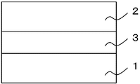
本発明の水栓金具は、図1に示すように、基材1上にアモルファスカーボン層2が形成されたものである。また、図2に示すように、基材1上に中間層3とアモルファスカーボン層2が形成されたものである。
As shown in FIG. 1, the faucet fitting of the present invention has an
(基材)
本発明の基材は、水栓金具である。水栓金具は、本体を構成する材料として、銅および銅合金、ステンレス鋼、亜鉛ダイキャストなどの金属やABSなどの樹脂が挙げられる。水栓金具の表面には、意匠性と耐食性等の機能を付与する目的で、めっきが処理されていることが好ましい。めっきの一例として、ニッケルめっき、クロムめっき、スズめっき、亜鉛めっき、銅めっき、金めっきなどが挙げられ、これらの表面処理が単一層または複数層形成された水栓金具も利用することが可能である。
さらに、水栓金具の表面性状は特に限定されるものではなく、光沢を有する鏡面、梨地、ヘアラインなどに適用することができる。
(Base material)
The base material of the present invention is a faucet fitting. The faucet fitting includes metals such as copper and copper alloys, stainless steel, and zinc die-cast, and resins such as ABS as materials constituting the main body. The surface of the faucet fitting is preferably subjected to plating for the purpose of imparting functions such as designability and corrosion resistance. Examples of plating include nickel plating, chromium plating, tin plating, galvanization, copper plating, and gold plating. It is also possible to use faucet fittings with a single or multiple layers of these surface treatments. is there.
Furthermore, the surface property of the faucet fitting is not particularly limited, and can be applied to glossy mirror surfaces, satin, hairlines, and the like.
(アモルファスカーボン層)
本発明のアモルファスカーボン層は、炭素原子および水素原子を含む非晶質の化合物である。炭素原子は、ダイヤモンド構造のsp3構造とグラファイト構造のsp2構造の2つの結合状態を有している。アモルファスカーボン層に含まれるsp3構造の炭素原子は、sp3構造の炭素原子とsp2構造の炭素原子の和に対して30at%以上含まれるとよい。アモルファスカーボン層に含まれるsp3構造の炭素原子を増加させることにより、アモルファスカーボン層の透光性を高めることができる。また、アモルファスカーボン層は、水素原子を含んでも含まなくても良いが、水素原子を含むほうがより好ましい。アモルファスカーボン層に含まれる水素原子は、アモルファスカーボン層の化学的な反応性を低下させ、同時に透光性を高めることができる。
アモルファスカーボン層は、従来から金属表面を高硬度の特徴を有するが、アモルファスカーボン層中の水素原子の量を増加させることにより、膜が弾性変形し易くなるため、水栓金具表面に使用させる際には清掃等による耐擦傷性の向上も期待できる。
また、アモルファスカーボン層に他の元素をドーピングすることによって、アモルファスカーボン層の表面の物性を改変することができる。たとえば、特許文献1で述べられているように、フッ素を含む原料ガスを導入することで、アモルファスカーボンの表面における水接触角を高めることにより、撥水性を付与することができる。
(Amorphous carbon layer)
The amorphous carbon layer of the present invention is an amorphous compound containing carbon atoms and hydrogen atoms. The carbon atom has two bonding states, an sp 3 structure having a diamond structure and an sp 2 structure having a graphite structure. Carbon atoms of sp 3 structure contained in the amorphous carbon layer may include more than 30 at% with respect to the sum of the carbon atoms of the carbon atoms and sp 2 structure of sp 3 structure. By increasing the carbon atoms of the sp 3 structure contained in the amorphous carbon layer, the translucency of the amorphous carbon layer can be enhanced. Further, the amorphous carbon layer may or may not contain hydrogen atoms, but it is more preferable that the amorphous carbon layer contain hydrogen atoms. Hydrogen atoms contained in the amorphous carbon layer can reduce the chemical reactivity of the amorphous carbon layer and at the same time increase the translucency.
Amorphous carbon layers have traditionally been characterized by their high hardness on the metal surface, but increasing the amount of hydrogen atoms in the amorphous carbon layer makes the membrane more easily elastically deformed. In addition, improvement of scratch resistance by cleaning or the like can be expected.
Further, the physical properties of the surface of the amorphous carbon layer can be modified by doping the amorphous carbon layer with other elements. For example, as described in
(中間層)
本願の中間層は、炭素、水素、ケイ素を含有する。中間層に含まれるSiの量は、アモルファスカーボン層とは明確な差を有しており、中間層はアモルファスカーボン層よりも多くのSiを含有する。中間層を設けることで、アモルファスカーボン層と基材の密着性を向上させることが可能となる。中間層のSiとCの結合は、アモルファスカーボン層と中間層の密着性を向上させることに寄与する。
(Middle layer)
The intermediate layer of the present application contains carbon, hydrogen, and silicon. The amount of Si contained in the intermediate layer has a clear difference from the amorphous carbon layer, and the intermediate layer contains more Si than the amorphous carbon layer. By providing the intermediate layer, it becomes possible to improve the adhesion between the amorphous carbon layer and the substrate. The bond between Si and C in the intermediate layer contributes to improving the adhesion between the amorphous carbon layer and the intermediate layer.
(膜厚)
膜厚を算出するための方法として、反射分光法、走査型電子顕微鏡(SEM)、透過型電子顕微鏡(TEM)、X線光電子分光法、GD−OESが挙げられる。
反射分光法は、基材上に形成されたアモルファスカーボン層の膜厚、もしくは基材上に形成された中間層の膜厚、もしくは基材上に形成されたアモルファスカーボン層と中間層の合計膜厚を求めることができる。反射分光法は、測定光の照射面積と同程度の領域の平均化された情報を膜厚値として算出する。微視的に見たサンプル面内方向の膜厚にバラツキがある場合でも、マクロな情報を膜厚値として得ることができる。具体的には、段落(0045)に記載の方法を用いることができる。
(Film thickness)
Examples of the method for calculating the film thickness include reflection spectroscopy, scanning electron microscope (SEM), transmission electron microscope (TEM), X-ray photoelectron spectroscopy, and GD-OES.
Reflection spectroscopy is based on the film thickness of the amorphous carbon layer formed on the substrate, the film thickness of the intermediate layer formed on the substrate, or the total film of the amorphous carbon layer and the intermediate layer formed on the substrate. Thickness can be determined. In reflection spectroscopy, averaged information of a region having the same extent as the measurement light irradiation area is calculated as a film thickness value. Even when there is variation in the film thickness in the sample in-plane direction as viewed microscopically, macro information can be obtained as the film thickness value. Specifically, the method described in paragraph (0045) can be used.
走査型電子顕微鏡の断面像によって膜厚を測定することができる。SEM/EDXを使用することにより、中間層とアモルファスカーボン層の分離が可能である。観察倍率は、基材と各層とが一つの観察視野内に収まる最大の倍率を用いると良い。EDXにより膜表面から基材と垂直方向に基材に到達するまで連続したSi元素の検出強度を測定することにより、膜厚方向のSi検出強度のプロファイルを得る。アモルファスカーボン層と中間層の境界は、Siの検出強度プロファイルの膜表面方向からの立ち上がり部において、最大検出強度の1/2となる地点として求められる。中間層と基材の境界は、Siの検出強度プロファイルの最大検出ピークから基材方向への立ち下がり部において、最大検出強度の1/2となる地点として求められる。アモルファスカーボン層と中間層の境界地点、中間層と基材の境界地点の2点の間を中間層の膜厚とする。アモルファスカーボン層の膜厚は、SEM画像より観察されるアモルファスカーボン層の表面地点と、上記の膜表面方向からのSi検出強度の立ち上がり部の中間層の境界地点から求める。アモルファスカーボン層の表面に沿った観察視野において少なくとも1μmの領域内で無作為に5点測定した値を、最終的な膜厚値とする。 The film thickness can be measured by a cross-sectional image of a scanning electron microscope. By using SEM / EDX, the intermediate layer and the amorphous carbon layer can be separated. As the observation magnification, it is preferable to use the maximum magnification that allows the base material and each layer to be within one observation field. A profile of the Si detection intensity in the film thickness direction is obtained by measuring the detection intensity of the continuous Si element from the film surface to the base material in the direction perpendicular to the base material by EDX. The boundary between the amorphous carbon layer and the intermediate layer is determined as a point that is ½ of the maximum detection intensity at the rising portion of the Si detection intensity profile from the film surface direction. The boundary between the intermediate layer and the base material is determined as a point that is ½ of the maximum detection intensity at the falling portion from the maximum detection peak of the Si detection intensity profile toward the base material. The film thickness of the intermediate layer is defined between two points of the boundary point between the amorphous carbon layer and the intermediate layer and the boundary point between the intermediate layer and the substrate. The film thickness of the amorphous carbon layer is determined from the surface point of the amorphous carbon layer observed from the SEM image and the boundary point of the intermediate layer at the rising portion of the Si detection intensity from the film surface direction. A value obtained by randomly measuring five points in a region of at least 1 μm in the observation visual field along the surface of the amorphous carbon layer is defined as a final film thickness value.
また、透過型電子顕微鏡の断面像によって膜厚を測定することができる。TEM/EDXを使用することにより、中間層とアモルファスカーボン層の分離が可能である。観察倍率は、基材と各層とが一つの観察視野内に収まる最大の倍率を用いる。観察倍率は、基材と各層とが一つの観察視野内に収まる最大の倍率を用いると良い。EDXにより膜表面から基材と垂直方向に基材に到達するまで連続したSi元素の検出強度を測定することにより、膜厚方向のSi検出強度のプロファイルを得る。アモルファスカーボン層と中間層の境界は、Siの検出強度プロファイルの膜表面方向からの立ち上がり部において、最大検出強度の1/2となる地点として求められる。中間層と基材の境界は、Siの検出強度プロファイルの最大検出ピークから基材方向への立ち下がり部において、最大検出強度の1/2となる地点として求められる。アモルファスカーボン層と中間層の境界地点、中間層と基材の境界地点の2点の間を中間層の膜厚とする。アモルファスカーボン層の膜厚は、TEM画像より観察されるアモルファスカーボン層の表面地点と、上記の膜表面方向からのSi検出強度の立ち上がり部の中間層の境界地点から求める。アモルファスカーボン層の表面に沿った観察視野において少なくとも100nmの領域内で無作為に5点測定した値を、最終的な膜厚値とする。 Further, the film thickness can be measured by a cross-sectional image of a transmission electron microscope. By using TEM / EDX, the intermediate layer and the amorphous carbon layer can be separated. As the observation magnification, the maximum magnification that allows the base material and each layer to be within one observation field is used. As the observation magnification, it is preferable to use the maximum magnification that allows the base material and each layer to be within one observation field. A profile of the Si detection intensity in the film thickness direction is obtained by measuring the detection intensity of the continuous Si element from the film surface to the base material in the direction perpendicular to the base material by EDX. The boundary between the amorphous carbon layer and the intermediate layer is determined as a point that is ½ of the maximum detection intensity at the rising portion of the Si detection intensity profile from the film surface direction. The boundary between the intermediate layer and the base material is determined as a point that is ½ of the maximum detection intensity at the falling portion from the maximum detection peak of the Si detection intensity profile toward the base material. The film thickness of the intermediate layer is defined between two points of the boundary point between the amorphous carbon layer and the intermediate layer and the boundary point between the intermediate layer and the substrate. The film thickness of the amorphous carbon layer is obtained from the surface point of the amorphous carbon layer observed from the TEM image and the boundary point of the intermediate layer at the rising portion of the Si detection intensity from the film surface direction. A value obtained by randomly measuring five points in a region of at least 100 nm in the observation visual field along the surface of the amorphous carbon layer is defined as a final film thickness value.
反射分光法により測定した膜厚値は、SEM/EDXまたはTEM/EDXによって測定した膜厚値との相関関係を求めることにより、換算係数を算定することができ、必要に応じて膜厚の値を修正することができる。すなわち、反射分光法によって測定が困難なサンプルであっても、SEM/EDXまたはTEM/EDXによって測定した膜厚値に対して上記の換算を行うことで、反射分光法によって求めた膜厚値と同等の値として取り扱うことが可能である。 The film thickness value measured by reflection spectroscopy can be calculated by calculating the correlation coefficient with the film thickness value measured by SEM / EDX or TEM / EDX, and the film thickness value can be calculated as necessary. Can be corrected. That is, even if the sample is difficult to measure by reflection spectroscopy, the film thickness value obtained by reflection spectroscopy can be obtained by performing the above conversion on the film thickness value measured by SEM / EDX or TEM / EDX. It can be handled as an equivalent value.
水栓金具の表面にアモルファスカーボン層を直接形成する際のアモルファスカーボン層の膜厚は12nmより大きくすることが好ましい。膜厚を12nmより大きくすることで、基材の被覆率が100%に近くなり、水垢除去性に対する効果を発現することが可能となる。12nm以下では、基材を十分に被覆できないため、水垢除去性に対する効果が得られない。アモルファスカーボン層を水栓金具上に直接形成する際の上限膜厚は、37nm以下とすることが好ましい。なお、ここで定めた膜厚は反射分光法により求めた値である。 The film thickness of the amorphous carbon layer when directly forming the amorphous carbon layer on the surface of the faucet fitting is preferably larger than 12 nm. By making the film thickness larger than 12 nm, the coverage of the base material is close to 100%, and the effect on the scale removal property can be exhibited. If the thickness is 12 nm or less, the substrate cannot be sufficiently covered, so that the effect on the scale removal property cannot be obtained. The upper limit film thickness when forming the amorphous carbon layer directly on the faucet fitting is preferably 37 nm or less. Note that the film thickness determined here is a value obtained by reflection spectroscopy.
水栓金具の表面に形成された中間層の膜厚は、好ましい下限値が1.4nm以上であり、好ましい上限値が、31nm以下、より好ましくは15nm以下、さらに好ましくは7nm以下である。中間層の上に形成されたアモルファスカーボン層の膜厚は、好ましい下限値が1.5nm以上であり、好ましい上限値が29nm以下、より好ましくは15nm以下、さらに好ましくは7nm以下である。なお、ここで定めた膜厚は反射分光法により求めた値である。
中間層は、アモルファスカーボン層が下地を均一に被覆するための表面を提供し、アモルファスカーボン層の膜厚ムラを緩和する効果があると考えられる。
As for the film thickness of the intermediate layer formed on the surface of the faucet fitting, a preferable lower limit value is 1.4 nm or more, and a preferable upper limit value is 31 nm or less, more preferably 15 nm or less, and further preferably 7 nm or less. The film thickness of the amorphous carbon layer formed on the intermediate layer has a preferable lower limit value of 1.5 nm or more, a preferable upper limit value of 29 nm or less, more preferably 15 nm or less, and further preferably 7 nm or less. Note that the film thickness determined here is a value obtained by reflection spectroscopy.
The intermediate layer is considered to have an effect of providing a surface for the amorphous carbon layer to uniformly coat the base, and reducing the film thickness unevenness of the amorphous carbon layer.
(意匠性)
水栓金具上にアモルファスカーボン層を形成する場合、および中間層とアモルファスカーボン層を形成する場合、いずれの場合においても、各層の膜厚が厚くなるにつれて、水栓金具の色味が変化し、色差ΔE*abは増大する。アモルファスカーボン層の単層、または、中間層とアモルファスカーボン層の合計膜厚が約100nm以下の薄膜の場合、膜厚と色差は比例関係となることを確認した。
(Creativity)
When forming an amorphous carbon layer on a faucet fitting, and when forming an intermediate layer and an amorphous carbon layer, in any case, as the film thickness of each layer increases, the color of the faucet fitting changes, The color difference ΔE * ab increases. In the case of a single layer of an amorphous carbon layer or a thin film having a total film thickness of an intermediate layer and an amorphous carbon layer of about 100 nm or less, it was confirmed that the film thickness and the color difference have a proportional relationship.
発明者らは、上記の膜厚と色調の関係性を利用して、水栓金具の意匠性を維持する膜厚の上限値を色差ΔE*abを指標として決定した。水栓金具の意匠性は、色差ΔE*abの異なるサンプルを用意し、官能評価によって判別が可能である。
例えば、水栓金具上にアモルファスカーボン層を形成した際の色差と膜厚の関係から、ΔE*ab=20以下となるアモルファスカーボン層の上限膜厚は、37nm以下であることが求められる。同様に、水栓金具上に中間層とアモルファスカーボン層を形成した際の色差と膜厚の関係から、ΔE*ab=20以下となる中間層とアモルファスカーボン層の上限膜厚は、それぞれ37nm以下と29nm以下であることが求められる。
膜厚の上限値は、各層の色差と膜厚の関係性から決定することができるため、色差変化の小さい場合には、より厚い膜を形成することが可能となる。
Inventors determined the upper limit of the film thickness which maintains the design property of a faucet metal fitting using the color difference (DELTA) E * ab as an index | index using the relationship between said film thickness and color tone. The design of the faucet fitting can be determined by preparing samples with different color differences ΔE * ab and sensory evaluation.
For example, from the relationship between the color difference and the film thickness when an amorphous carbon layer is formed on a faucet fitting, the upper limit film thickness of the amorphous carbon layer where ΔE * ab = 20 or less is required to be 37 nm or less. Similarly, from the relationship between the color difference and the film thickness when the intermediate layer and the amorphous carbon layer are formed on the faucet fitting, the upper limit film thickness of the intermediate layer and the amorphous carbon layer where ΔE * ab = 20 or less is 37 nm or less, respectively. And 29 nm or less.
Since the upper limit value of the film thickness can be determined from the relationship between the color difference and film thickness of each layer, a thicker film can be formed when the color difference change is small.
(色差)
色差の測定には、分光測色計などを用いて測定することが可能である。成膜前の色差値と成膜後の色差値の差分により求めることができる。成膜前の色差値は、成膜前の基材のL*、a*、b*を測定することで求めることができる。また、成膜後の色差値は成膜後の基材のL*、a*、b*を測定することで求めることができる。成膜前後のL*、a*、b*につき、それぞれの差分より、ΔL*、Δa*、Δb*値を算出し、色差の定義より、ΔE*ab={(ΔL*)2+(Δa*)2+(Δb*)2}1/2より、色差ΔE*abを算出することができる。
(Color difference)
The color difference can be measured using a spectrocolorimeter or the like. It can be obtained from the difference between the color difference value before film formation and the color difference value after film formation. The color difference value before film formation can be obtained by measuring L *, a *, and b * of the base material before film formation. The color difference value after film formation can be obtained by measuring L *, a *, and b * of the substrate after film formation. ΔL *, Δa *, and Δb * values are calculated from the respective differences for L *, a *, and b * before and after film formation, and ΔE * ab = {(ΔL *) 2 + (Δa *) Color difference ΔE * ab can be calculated from 2 + (Δb *) 2 } 1/2 .
また、アモルファスカーボン成膜後の基材に対しては、アモルファスカーボン膜を機械研磨による物理的除去、あるいはアルゴンプラズマや酸素プラズマを用いたエッチングにより除去することで、下地の金属層を露出させ、この状態を成膜前としてL*、a*、b*値を測定することで、色差を算出することが可能である。 In addition, for the substrate after the amorphous carbon film formation, by removing the amorphous carbon film by physical removal by mechanical polishing or etching using argon plasma or oxygen plasma, the underlying metal layer is exposed, By measuring the L *, a *, and b * values with this state before film formation, the color difference can be calculated.
(成膜方法)
水栓金具にアモルファスカーボン層および中間層を形成する方法としては、PVD法(スパッタ法、イオンプレーティング法など)またはCVD法(プラズマCVD法、イオン化蒸着法など)が可能である。
(Film formation method)
As a method for forming the amorphous carbon layer and the intermediate layer on the faucet fitting, PVD method (sputtering method, ion plating method, etc.) or CVD method (plasma CVD method, ionized vapor deposition method, etc.) can be used.
(前処理)
本発明のある実施形態として、基材表面にアモルファスカーボン層を形成する際に、基材の前処理として、基材表面の調整を行うことができる。
前処理は、(1)基材表面に付着した有機や無機の吸着物を除去、(2)酸化物層の除去による密着性の向上、(3)基材表面粗さの調製、(4)基材表面のプラズマにより活性化等の目的で実施される。前処理は、中間層やアモルファスカーボン層を形成する同一プロセスで行っても良いし、別プロセスとして行っても良い。
(Preprocessing)
As an embodiment of the present invention, when the amorphous carbon layer is formed on the substrate surface, the substrate surface can be adjusted as a pretreatment of the substrate.
The pretreatment includes (1) removing organic and inorganic adsorbates adhering to the substrate surface, (2) improving adhesion by removing the oxide layer, (3) adjusting the substrate surface roughness, (4) This is performed for the purpose of activation or the like by the plasma on the substrate surface. The pretreatment may be performed in the same process for forming the intermediate layer or the amorphous carbon layer, or may be performed as a separate process.
本発明では、前処理として、中間層形成前にArガスを用いたスパッタリングを実施するのが好ましい。 In the present invention, it is preferable to perform sputtering using Ar gas as the pretreatment before forming the intermediate layer.
本発明のアモルファスカーボン層及び中間層はプラズマCVD法を用いて以下のように形成することができる。 The amorphous carbon layer and the intermediate layer of the present invention can be formed as follows using a plasma CVD method.
(アモルファスカーボン層成膜工程)
基材に高周波パルス電圧を印加することによって、基材の周りに存在する原料ガスがプラズマ化し、原料のイオンやラジカル種が生成する。生成したイオンやラジカル種は、基材表面において互いに化学結合を繰り返すことにより、基材上に堆積していく。堆積の極めて初期段階においては、アモルファスカーボンの島状の核生成が起こると考えられ、堆積が進むにつれて基材表面を次第に被覆して、最終的には均一な膜が形成される。
(Amorphous carbon layer deposition process)
By applying a high frequency pulse voltage to the base material, the raw material gas existing around the base material is turned into plasma, and raw material ions and radical species are generated. The generated ions and radical species are deposited on the substrate by repeating chemical bonds with each other on the substrate surface. In the very initial stage of deposition, it is thought that island nucleation of amorphous carbon occurs, and as the deposition proceeds, the substrate surface is gradually covered, and finally a uniform film is formed.
アモルファスカーボン層の原料ガスとしては、アセチレン、プロパン、ブタン、メタン、ベンゼン、トルエン、ヘキサン、クロルベンゼンからなる群より選ばれた一以上のガスを使用することができる。 As a raw material gas for the amorphous carbon layer, one or more gases selected from the group consisting of acetylene, propane, butane, methane, benzene, toluene, hexane, and chlorobenzene can be used.
(中間層成膜工程)
原料ガスを変えることで、アモルファスカーボン層と同様の手法で形成することが可能である。
(Intermediate layer deposition process)
By changing the source gas, it can be formed in the same manner as the amorphous carbon layer.
中間層の原料ガスとしては、ヘキサメチルジシロキサン(HMDSO)、テトラメチルシラン(TMS)、テトラエトオキシシリコン(TEOS)からなる群より選ばれた一以上のガスを第一の成分として使用できる。また、水素、酸素からなる群より選ばれた一以上のガスを第二の成分として第一の成分と混合して使用できる。水栓金具における中間層は透光性が要求されるため、原料ガスとして、HMDSOを用いることにより意匠性の変化を抑制することができる。また、HMDSOを使用する代わりに、TMSと酸素の混合ガスを使用しても良い。
中間層の成膜方法としては、カーボンイオンやプロトンおよびその化合物からなるイオン注入などが可能であるほか、上記ガス種とアモルファスカーボン原料ガスとの混合によるミキシング層を形成しても良い。
As the raw material gas for the intermediate layer, one or more gases selected from the group consisting of hexamethyldisiloxane (HMDSO), tetramethylsilane (TMS), and tetraethoxysilicon (TEOS) can be used as the first component. Also, one or more gases selected from the group consisting of hydrogen and oxygen can be mixed with the first component as the second component. Since the intermediate layer in the faucet fitting is required to have translucency, a change in design can be suppressed by using HMDSO as a raw material gas. Further, instead of using HMDSO, a mixed gas of TMS and oxygen may be used.
As a method for forming the intermediate layer, ion implantation including carbon ions, protons, and compounds thereof is possible, and a mixing layer may be formed by mixing the gas species and the amorphous carbon source gas.
(成膜装置)
成膜には、プラズマCVD成膜装置を用いた。
(Deposition system)
For film formation, a plasma CVD film forming apparatus was used.
基材として、黄銅上に電解ニッケルめっきを15μmと電解クロムめっきを0.1μm施した水栓金具を用いた。
また、めっき表面の汚れを除去するために、イオン交換水およびアセトンによる超音波洗浄を順次実施した。
As a base material, a faucet fitting having 15 μm of electrolytic nickel plating and 0.1 μm of electrolytic chrome plating on brass was used.
Moreover, in order to remove the stain | pollution | contamination of a plating surface, the ultrasonic cleaning by ion-exchange water and acetone was implemented sequentially.
前述した基材を、前述した成膜装置に設置し、下記のステップに示す手順で成膜を行った。 The base material described above was placed in the film forming apparatus described above, and film formation was performed according to the procedure shown in the following steps.
ステップ1:(前処理工程)
基材を真空容器の内部にセッティングし、真空排気装置により高真空状態(0.00133Pa以下)まで減圧した。次に、アルゴンガスを導入し、真空容器内の圧力が0.7Paとなるように調整した。高周波出力500W、基材温度を100℃以下とし、約5分間の処理を行うことにより、基材表面を調整した。
Step 1: (Pretreatment process)
The base material was set inside the vacuum vessel, and the pressure was reduced to a high vacuum state (0.00133 Pa or less) by a vacuum exhaust device. Next, argon gas was introduced and the pressure in the vacuum vessel was adjusted to 0.7 Pa. The surface of the base material was adjusted by performing a treatment for about 5 minutes at a high frequency output of 500 W and a base material temperature of 100 ° C. or lower.
ステップ2:(中間層成膜工程)
次に、ヘキサメチルジシロキサン(HMDSO)を導入し、真空容器内の圧力が0.2Paとなるように調整した。高周波出力300W、基材温度を100℃以下とし、所定の処理時間の成膜を行うことにより、基材表面に中間層を形成した。
Step 2: (Intermediate layer deposition process)
Next, hexamethyldisiloxane (HMDSO) was introduced and the pressure in the vacuum vessel was adjusted to 0.2 Pa. An intermediate layer was formed on the surface of the base material by carrying out film formation for a predetermined processing time with a high frequency output of 300 W and a base material temperature of 100 ° C. or lower.
ステップ3:(アモルファスカーボン層成膜工程)
次に、アセチレンガスを導入し、真空容器内の圧力が0.2Paとなるように調整した。高周波出力300W、基材温度を100℃以下とし、所定の処理時間の成膜を行うことにより、中間層上にアモルファスカーボン層を形成し、各サンプルを得た。
Step 3: (Amorphous carbon layer deposition process)
Next, acetylene gas was introduced and adjusted so that the pressure in the vacuum vessel was 0.2 Pa. An amorphous carbon layer was formed on the intermediate layer by forming a film for a predetermined processing time with a high-frequency output of 300 W and a base material temperature of 100 ° C. or less, and each sample was obtained.
ステップ1、ステップ2およびステップ3において、所定の処理時間に変更することにより、表1に記載の実施例1〜4および比較例3,4を作製した。
In
ステップ1およびステップ3において、所定の処理時間に変更することにより、表1に記載の実施例5および比較例1,2を作製した。
In
(水垢汚れの清掃性評価)
各サンプルのアモルファスカーボン層の表面に、水道水を滴下し、25℃、60%の空気中で24時間放置することにより、基材表面に水垢を形成した。
形成した水垢の清掃性は、一軸往復式の摺動試験装置によって水垢汚れの清掃性を評価した。水垢を清掃するための摺動素材は、一般家庭で使用される浴室清掃用の市販のスポンジ(品名スコッチブライト、品番BM−12K、メーカー住友スリーエム社製)を使用した。摺動面にかかる面圧は、100g/cm2、摺動子の移動速度は、35mm/secとし、摺動子を一定方向に10往復させた後に、水垢が残存しているかを目視で判断し、水垢が除去されたものを○、除去されていないものを×として評価した。表1に水垢除去性の評価結果を示す。
(Evaluation of cleanability of scale dirt)
Tap water was dropped on the surface of the amorphous carbon layer of each sample and left in air at 25 ° C. and 60% for 24 hours to form scale on the substrate surface.
The cleanability of the formed scale was evaluated by using a uniaxial reciprocating sliding test device. A commercially available sponge for cleaning bathrooms (product name Scotch Bright, product number BM-12K, manufactured by Sumitomo 3M Limited) used for general households was used as a sliding material for cleaning scales. The surface pressure applied to the sliding surface is 100 g / cm 2 , the moving speed of the slider is 35 mm / sec, and it is judged visually that the scale remains after the slider is reciprocated 10 times in a certain direction. Then, the case where the scale was removed was evaluated as ◯, and the case where the scale was not removed was evaluated as X. Table 1 shows the evaluation results of scale removability.
(膜厚)
各サンプルの膜厚は、反射分光法を用いて以下のように測定した。
測定装置は、分光エリプソメーター(型番:FE−5000、大塚電子株式会社製)および、反射分光膜厚計(型番:FE−3000、大塚電子株式会社製)を用いた。まず、分光エリプソメーターを用いて、基材とアモルファスカーボン膜および中間層の光学特性の測定より、屈折率「n(λ)」および消衰係数「k(λ)」を求めた。次に、基材上に形成したアモルファスカーボン層および中間層のそれぞれについて光学特性を測定し、基材と同様に屈折率および消衰係数を求めた。これらの情報をもとに、中間層、アモルファスカーボン層のそれぞれについて、膜厚解析モデルを立てた。中間層の膜厚測定には、金属基材上に中間層の成膜処理時間を振って作成したサンプルに対して、解析値を算出した。アモルファスカーボン層の膜厚についても、中間層と同様にして、アモルファスカーボン層の解析値を算出した。成膜処理時間に対して、各層の膜厚解析値をプロットし、原点を通る最小二乗近似によって求めた検量線を作成した。検量線に各サンプルの成膜処理時間を代入して、中間層とアモルファスカーボン層の膜厚を求めた。
(Film thickness)
The film thickness of each sample was measured as follows using reflection spectroscopy.
As a measuring apparatus, a spectroscopic ellipsometer (model number: FE-5000, manufactured by Otsuka Electronics Co., Ltd.) and a reflection spectral film thickness meter (model number: FE-3000, manufactured by Otsuka Electronics Co., Ltd.) were used. First, using a spectroscopic ellipsometer, the refractive index “n (λ)” and the extinction coefficient “k (λ)” were determined by measuring the optical properties of the substrate, the amorphous carbon film, and the intermediate layer. Next, the optical properties of each of the amorphous carbon layer and the intermediate layer formed on the substrate were measured, and the refractive index and extinction coefficient were obtained in the same manner as the substrate. Based on these information, a film thickness analysis model was established for each of the intermediate layer and the amorphous carbon layer. For the measurement of the film thickness of the intermediate layer, an analysis value was calculated for a sample prepared by varying the film formation processing time of the intermediate layer on the metal substrate. Regarding the film thickness of the amorphous carbon layer, the analysis value of the amorphous carbon layer was calculated in the same manner as in the intermediate layer. The thickness analysis value of each layer was plotted against the film formation time, and a calibration curve obtained by least square approximation passing through the origin was created. The film formation time of each sample was substituted into the calibration curve, and the film thicknesses of the intermediate layer and the amorphous carbon layer were obtained.
(色差)
各サンプルの色差の測定には、分光測色計(型番:CM−2600d、コニカミノルタ社製)を用いた。測定光源は、F2を用いた。測定器に白色校正板(#YYYY)にて校正を実施した。まず、成膜前の基材のL*、a*、b*を測定し、成膜前の色差値とした。次に、成膜後の基材のL*、a*、b*を測定し、成膜後の色差値とした。成膜前後のL*、a*、b*につき、それぞれの差分より、ΔL*、Δa*、Δb*値を算出した。色差の定義より、ΔE*ab={(ΔL*)2+(Δa*)2+(Δb*)2}1/2より、色差ΔE*abを算出した。
(Color difference)
A spectrocolorimeter (model number: CM-2600d, manufactured by Konica Minolta) was used to measure the color difference of each sample. F2 was used as the measurement light source. The measuring device was calibrated with a white calibration plate (#YYYY). First, L *, a *, and b * of the base material before film formation were measured and used as color difference values before film formation. Next, L *, a *, and b * of the base material after film formation were measured and used as color difference values after film formation. ΔL *, Δa *, and Δb * values were calculated from the respective differences for L *, a *, and b * before and after film formation. From the definition of color difference, the color difference ΔE * ab was calculated from ΔE * ab = {(ΔL *) 2 + (Δa *) 2 + (Δb *) 2 } 1/2 .
(意匠性の評価)
各サンプルについて、意匠性の評価を実施した。評価方法は、表面がクロムめっき処理された水栓金具との色味の比較により行った。被験者30人の視覚による官能評価とし、次に示す4段階の基準で判定した。4段階の基準の区分には、被験者30人中20人以上の判定結果が一致した結果によって決定した。評価結果を表1に示す。
「×」:水栓金具として違和感を感じる色味
「△」:水栓金具として受容される色味
「○」:クロムめっき品と同一の空間で使用する際に違和感を感じる色味
「◎」:クロムめっき品と同一の空間で使用する際に違和感を感じない色味
とした。
(Evaluation of design properties)
About each sample, design property evaluation was implemented. The evaluation method was performed by comparing the color with a faucet fitting whose surface was chrome-plated. The sensory evaluation was performed visually by 30 subjects, and the determination was made according to the following four criteria. The classification of the four-stage criteria was determined based on the result that the judgment results of 20 or more of 30 subjects matched. The evaluation results are shown in Table 1.
“×”: Color that feels uncomfortable as a faucet fitting “△”: Color that is accepted as a faucet fitting “○”: Color that feels uncomfortable when used in the same space as a chrome-plated product “◎” : A color that does not give an uncomfortable feeling when used in the same space as the chrome-plated product.

Claims (6)
基材とアモルファスカーボン層との間に設けられ、炭素、水素、及びケイ素を含有する中間層をさらに備え、
前記アモルファスカーボン層が形成される前後の色差値の差分である色差ΔE*abが、2.5以上17.8以下であることを特徴とする防汚性水栓金具。 A faucet fitting in which an amorphous carbon layer is formed on the surface of a base material subjected to at least one of chromium plating and nickel plating,
An intermediate layer provided between the substrate and the amorphous carbon layer and containing carbon, hydrogen, and silicon;
The antifouling faucet fitting, wherein a color difference ΔE * ab, which is a difference between color difference values before and after the amorphous carbon layer is formed, is 2.5 or more and 17.8 or less .
前記アモルファスカーボン層が前記基材の表面に直接設けられており、
前記アモルファスカーボン層の膜厚が12nmより厚く37nm以下であることを特徴とする防汚性水栓金具。 A faucet fitting in which an amorphous carbon layer is formed on the surface of a base material subjected to at least one of chromium plating and nickel plating,
The amorphous carbon layer is directly provided on the surface of the substrate;
The antifouling faucet metal fitting, wherein the amorphous carbon layer has a thickness greater than 12 nm and not greater than 37 nm.
Priority Applications (1)
| Application Number | Priority Date | Filing Date | Title |
|---|---|---|---|
| JP2013081577A JP6213889B2 (en) | 2013-04-09 | 2013-04-09 | Faucet fittings |
Applications Claiming Priority (1)
| Application Number | Priority Date | Filing Date | Title |
|---|---|---|---|
| JP2013081577A JP6213889B2 (en) | 2013-04-09 | 2013-04-09 | Faucet fittings |
Publications (3)
| Publication Number | Publication Date |
|---|---|
| JP2014202047A JP2014202047A (en) | 2014-10-27 |
| JP2014202047A5 JP2014202047A5 (en) | 2015-12-24 |
| JP6213889B2 true JP6213889B2 (en) | 2017-10-18 |
Family
ID=52352730
Family Applications (1)
| Application Number | Title | Priority Date | Filing Date |
|---|---|---|---|
| JP2013081577A Expired - Fee Related JP6213889B2 (en) | 2013-04-09 | 2013-04-09 | Faucet fittings |
Country Status (1)
| Country | Link |
|---|---|
| JP (1) | JP6213889B2 (en) |
Families Citing this family (3)
| Publication number | Priority date | Publication date | Assignee | Title |
|---|---|---|---|---|
| JP6028878B2 (en) * | 2015-02-23 | 2016-11-24 | Toto株式会社 | Glass parts for water |
| EP3059330A1 (en) | 2015-02-23 | 2016-08-24 | Toto Ltd. | Wet area member |
| JP6804037B2 (en) * | 2016-09-02 | 2020-12-23 | Toto株式会社 | Water spouting device |
Family Cites Families (2)
| Publication number | Priority date | Publication date | Assignee | Title |
|---|---|---|---|---|
| JP3366680B2 (en) * | 1993-02-05 | 2003-01-14 | 東陶機器株式会社 | Ceramic valve member and method of manufacturing the same |
| JP2003336751A (en) * | 2002-05-17 | 2003-11-28 | Sumitomo Electric Ind Ltd | Alumina ceramics valve element and warm water faucet valve using it |
-
2013
- 2013-04-09 JP JP2013081577A patent/JP6213889B2/en not_active Expired - Fee Related
Also Published As
| Publication number | Publication date |
|---|---|
| JP2014202047A (en) | 2014-10-27 |
Similar Documents
| Publication | Publication Date | Title |
|---|---|---|
| Boryło et al. | Structure and properties of Al2O3 thin films deposited by ALD process | |
| Harkonen et al. | Sealing of hard CrN and DLC coatings with atomic layer deposition | |
| Abdallah et al. | Structural, mechanical, electrical and wetting properties of ZrNx films deposited by Ar/N2 vacuum arc discharge: Effect of nitrogen partial pressure | |
| Chu et al. | Substrate bias effects on mechanical and tribological properties of substitutional solid solution (Ti, Al) N films prepared by reactive magnetron sputtering | |
| Delfani-Abbariki et al. | Enhancing the adhesion of diamond-like carbon films to steel substrates using silicon-containing interlayers | |
| JP6213889B2 (en) | Faucet fittings | |
| Aissani et al. | Relationship between structure, surface topography and tribo-mechanical behavior of Ti-N thin films elaborated at different N2 flow rates | |
| US9790592B2 (en) | Decorative article having black hard coating film | |
| Wang et al. | The influence of Ni concentration on the structure, mechanical and tribological properties of Ni–CrSiN coatings in seawater | |
| Miletić et al. | Influence of substrate roughness on adhesion of TiN coatings | |
| Leppaniemi et al. | Effect of surface wear on corrosion protection of steel by CrN coatings sealed with atomic layer deposition | |
| Jeong et al. | Fabrication and evaluation of protective SiOx layers using plasma-enhanced chemical vapor deposition | |
| Lyytinen et al. | Nanotribological, nanomechanical and interfacial characterization of atomic layer deposited TiO2 on a silicon substrate | |
| Lin et al. | Fabrication of High Transparency Diamond‐Like Carbon Film Coating on D263T Glass at Room Temperature as an Antireflection Layer | |
| JP2016513181A (en) | Decorative, jet black coating | |
| US10526241B2 (en) | Scratch-resistant coatings with improved cleanability, substrates with scratch-resistant coatings with improved cleanability, and methods for producing same | |
| Sharifahmadian et al. | Mechanically robust hydrophobic fluorine-doped diamond-like carbon film on glass substrate | |
| Polychronopoulou et al. | The nanostructure, wear and corrosion performance of arc-evaporated CrBxNy nanocomposite coatings | |
| JP2015193911A (en) | Plumbing component | |
| Chen et al. | Chemical inertness of Ta–Si–N coatings in glass molding | |
| James et al. | Metallic Adhesive Layers for Ag‐Based First Surface Mirrors | |
| TW200303930A (en) | Corrosion and abrasion resistant decorative coating | |
| CN111263832B (en) | Sanitary equipment component | |
| Takarada et al. | Structural dependence of corrosion resistance of amorphous carbon films against nitric acid | |
| US10029233B2 (en) | Wet area member |
Legal Events
| Date | Code | Title | Description |
|---|---|---|---|
| A521 | Request for written amendment filed |
Free format text: JAPANESE INTERMEDIATE CODE: A523 Effective date: 20151105 |
|
| A621 | Written request for application examination |
Free format text: JAPANESE INTERMEDIATE CODE: A621 Effective date: 20151105 |
|
| A977 | Report on retrieval |
Free format text: JAPANESE INTERMEDIATE CODE: A971007 Effective date: 20160727 |
|
| A131 | Notification of reasons for refusal |
Free format text: JAPANESE INTERMEDIATE CODE: A131 Effective date: 20160809 |
|
| A521 | Request for written amendment filed |
Free format text: JAPANESE INTERMEDIATE CODE: A523 Effective date: 20160926 |
|
| A131 | Notification of reasons for refusal |
Free format text: JAPANESE INTERMEDIATE CODE: A131 Effective date: 20170306 |
|
| A521 | Request for written amendment filed |
Free format text: JAPANESE INTERMEDIATE CODE: A523 Effective date: 20170417 |
|
| TRDD | Decision of grant or rejection written | ||
| A01 | Written decision to grant a patent or to grant a registration (utility model) |
Free format text: JAPANESE INTERMEDIATE CODE: A01 Effective date: 20170828 |
|
| R150 | Certificate of patent or registration of utility model |
Ref document number: 6213889 Country of ref document: JP Free format text: JAPANESE INTERMEDIATE CODE: R150 |
|
| A61 | First payment of annual fees (during grant procedure) |
Free format text: JAPANESE INTERMEDIATE CODE: A61 Effective date: 20170910 |
|
| LAPS | Cancellation because of no payment of annual fees |