JP6213397B2 - Rotating electric machine - Google Patents
Rotating electric machine Download PDFInfo
- Publication number
- JP6213397B2 JP6213397B2 JP2014137542A JP2014137542A JP6213397B2 JP 6213397 B2 JP6213397 B2 JP 6213397B2 JP 2014137542 A JP2014137542 A JP 2014137542A JP 2014137542 A JP2014137542 A JP 2014137542A JP 6213397 B2 JP6213397 B2 JP 6213397B2
- Authority
- JP
- Japan
- Prior art keywords
- housing
- shielding wall
- power
- electrical machine
- rotating electrical
- Prior art date
- Legal status (The legal status is an assumption and is not a legal conclusion. Google has not performed a legal analysis and makes no representation as to the accuracy of the status listed.)
- Expired - Fee Related
Links
Images


Classifications
-
- H—ELECTRICITY
- H02—GENERATION; CONVERSION OR DISTRIBUTION OF ELECTRIC POWER
- H02K—DYNAMO-ELECTRIC MACHINES
- H02K9/00—Arrangements for cooling or ventilating
- H02K9/02—Arrangements for cooling or ventilating by ambient air flowing through the machine
- H02K9/04—Arrangements for cooling or ventilating by ambient air flowing through the machine having means for generating a flow of cooling medium
- H02K9/06—Arrangements for cooling or ventilating by ambient air flowing through the machine having means for generating a flow of cooling medium with fans or impellers driven by the machine shaft
-
- H—ELECTRICITY
- H02—GENERATION; CONVERSION OR DISTRIBUTION OF ELECTRIC POWER
- H02K—DYNAMO-ELECTRIC MACHINES
- H02K5/00—Casings; Enclosures; Supports
- H02K5/04—Casings or enclosures characterised by the shape, form or construction thereof
- H02K5/18—Casings or enclosures characterised by the shape, form or construction thereof with ribs or fins for improving heat transfer
-
- H—ELECTRICITY
- H02—GENERATION; CONVERSION OR DISTRIBUTION OF ELECTRIC POWER
- H02K—DYNAMO-ELECTRIC MACHINES
- H02K11/00—Structural association of dynamo-electric machines with electric components or with devices for shielding, monitoring or protection
- H02K11/04—Structural association of dynamo-electric machines with electric components or with devices for shielding, monitoring or protection for rectification
- H02K11/049—Rectifiers associated with stationary parts, e.g. stator cores
- H02K11/05—Rectifiers associated with casings, enclosures or brackets
Landscapes
- Engineering & Computer Science (AREA)
- Power Engineering (AREA)
- Physics & Mathematics (AREA)
- Thermal Sciences (AREA)
- Motor Or Generator Cooling System (AREA)
- Motor Or Generator Frames (AREA)
Description
本発明は、ローターの回転によって発電を行う、または電力の供給によってローターが回転する回転電機に関する。 The present invention relates to a rotating electrical machine that generates electric power by rotating a rotor or rotates a rotor by supplying electric power.
ハウジング内に設けられたローターの回転によって、ローターの径方向外側と対向するように配置されたステータにおいて発電を行う発電機においては、発生した電力を直流に変換するために、パワー素子を有する電力変換装置がハウジング内に配置されて使用されるものがある。また、電力の供給によってローターが回転する電動機においても、ステータに供給する電力を交流に変換するために、ハウジング内に電力変換装置が設けられているものがある。さらに、発電機と電動機の2つの機能を併せ持つ電動発電機において、上記の電力変換装置をハウジング内に設けた、いわゆる機電一体の回転電機とするものがある。このような構成において、電力変換装置に含まれるパワー素子は、その作動によって発熱するため、発電機、電動機および電動発電機においては、ハウジング内において熱が滞留するという問題があった。 In a generator that generates electric power in a stator that is arranged so as to face the radially outer side of the rotor by rotation of a rotor provided in the housing, electric power having a power element is used to convert the generated electric power into direct current Some conversion devices are used in a housing. Some electric motors in which the rotor rotates by the supply of electric power are provided with a power conversion device in the housing in order to convert electric power supplied to the stator into alternating current. Further, in a motor generator having both functions of a generator and an electric motor, there is a motor-generator-integrated rotating electric machine in which the above-described power conversion device is provided in a housing. In such a configuration, since the power element included in the power conversion device generates heat due to its operation, the generator, the motor, and the motor generator have a problem that heat is accumulated in the housing.
これに対し、交流発電機内に設けられ、パワー素子の冷却機能を備えた電力変換装置に関する従来技術があった(例えば、特許文献1参照)。当該従来技術においては、ローターの回転軸に直交するように平板状の取付部材を設け、取付部材の一面に放射状に複数の放熱フィンを形成し、他面にパワー素子が取り付けられている。さらに、交流発電機のハウジングに空気導入孔を設け、空気導入孔から内部に進入した冷却風が取付部材を通過することにより、放熱フィンにおいて放熱が行われ、パワー素子の冷却が行われる。 On the other hand, there has been a conventional technology related to a power conversion device provided in an AC generator and provided with a power element cooling function (see, for example, Patent Document 1). In the prior art, a flat mounting member is provided so as to be orthogonal to the rotation axis of the rotor, a plurality of radiation fins are formed radially on one surface of the mounting member, and a power element is mounted on the other surface. Furthermore, an air introduction hole is provided in the housing of the AC generator, and the cooling air entering the inside through the air introduction hole passes through the mounting member, so that heat is radiated in the radiation fins and the power element is cooled.
しかしながら、上述した従来技術による電力変換装置を備えた交流発電機においては、冷却風とともに、外部の塵、砂等の異物または水分がハウジング内に進入することがある。交流発電機の内部には、ローターへ電力を供給するための一対の給電ブラシ、およびローターに形成され、給電ブラシと摺動する一対のスリップリングが設けられており、ブラシとスリップリングとの摺動部は、交流発電機の内部に奥まっている。
一方、給電ブラシの磨耗粉がブラシホルダ内に堆積すると、給電ブラシの早期磨耗やスリップリング間の絶縁不良を発生させることがある。この問題を解決するために、ブラシホルダには磨耗粉抜け通路を設ける必要があるが、一方でブラシホルダ内側とブラシホルダ外側で異物または水分の進入経路ができる。
ここで、冷却機の放熱フィンが放射状に配置されているため、放熱フィン間、および上記の進入経路を経由して、進入した異物等が給電ブラシとローターに形成されたスリップリングとの摺動部に入る可能性が高まる。給電ブラシとスリップリングとの間の摺動部に異物が入り込んだ場合、給電ブラシの早期磨耗や給電ブラシとスリップリングとの間の接触不良を発生させることがある。
However, in the AC generator including the above-described conventional power converter, foreign matter such as external dust or sand or moisture may enter the housing together with the cooling air. Inside the AC generator, a pair of power supply brushes for supplying power to the rotor and a pair of slip rings formed on the rotor and sliding with the power supply brush are provided. The moving part is hidden inside the AC generator.
On the other hand, when the power brush wear powder accumulates in the brush holder, it may cause early wear of the power supply brush and poor insulation between slip rings. In order to solve this problem, it is necessary to provide a wear powder passage in the brush holder. On the other hand, a foreign substance or moisture ingress path can be formed inside and outside the brush holder.
Here, since the heat dissipating fins of the cooler are arranged radially, the foreign matter that has entered between the heat dissipating fins and the above-described approach path slides between the power supply brush and the slip ring formed on the rotor. The possibility of entering the club increases. When foreign matter enters a sliding portion between the power supply brush and the slip ring, premature wear of the power supply brush or contact failure between the power supply brush and the slip ring may occur.
また、上述した従来技術による電力変換装置で、冷却性の向上のため、限られたスペース内において放熱面積を増やそうとすると、放射状の放熱フィンの枚数を増やことが必要になる。その結果、放熱フィンの厚みが小さくなるので、放熱フィンは部分的に欠け易くなる。すなわち、製造工程で、より慎重な取り扱いが必要となるので、製造コストが上昇すると共に、組付け後の使用環境によっては振動などによる欠けによる冷却性の低下や短絡故障を生ずる可能性が高まる。
本発明は上記事情に鑑みてなされたものであり、その目的は、給電ブラシの信頼性を向上させることのできる回転電機を提供することにある。
Further, in the above-described power converter according to the prior art, in order to improve the cooling performance, if the heat radiation area is increased in a limited space, it is necessary to increase the number of radial heat radiation fins. As a result, since the thickness of the radiating fin is reduced, the radiating fin is likely to be partially chipped. That is, since more careful handling is required in the manufacturing process, the manufacturing cost increases, and depending on the usage environment after assembly, there is a high possibility of a decrease in cooling performance or short circuit failure due to chipping due to vibration or the like.
This invention is made | formed in view of the said situation, The objective is to provide the rotary electric machine which can improve the reliability of an electric power feeding brush.
上述した課題を解決するために、請求項1に係る回転電機の発明は、ハウジング(2、3、11)と、ハウジングに固定されたステータ(4)と、ハウジングに対して回転可能に取り付けられ、ステータに対して半径方向に対向したローター(5)と、ハウジングに取り付けられ、ローターの回転軸(5d)に設けられたスリップリング(5e、5f)と摺接してローターに電力を供給する給電ブラシ(9a、9b)と、ステータに発生した電力を直流に変換する、または、ステータへの電力を交流に変換する電力変換素子(15)と、電力変換素子が取り付けられるとともに、放熱用フィン(14b)が形成され、ハウジングに取り付けられた通風部(14a、14b)と、を備え、ハウジングを貫通した空気導入孔(12)からハウジング内に進入した冷却空気が、通風部を通過し、電力変換素子を冷却する回転電機(1)であって、空気導入孔と給電ブラシとの間には、空気導入孔から進入した冷却空気が給電ブラシへ到達することを阻止する遮蔽壁(14c)が形成され、通風部と遮蔽壁とが一体化されて素子取付部材(14)が形成され、素子取付部材は、半径方向に延びる平板状に形成された底面部(14a)を有し、底面部の一面(14d)には電力変換素子が固定され、底面部の他面(14e)には遮蔽壁が回転軸方向に突出するように形成されている。 In order to solve the above-described problems, the invention of the rotating electrical machine according to claim 1 is provided with a housing (2, 3, 11), a stator (4) fixed to the housing, and rotatably attached to the housing. , A rotor (5) opposed to the stator in the radial direction, and a power supply that is attached to the housing and slidably contacts a slip ring (5e, 5f) provided on a rotating shaft (5d) of the rotor to supply power to the rotor A brush (9a, 9b) and a power conversion element (15) for converting electric power generated in the stator into direct current, or converting electric power to the stator into alternating current, and a power conversion element are attached, and a fin ( 14b) and a ventilation section (14a, 14b) attached to the housing, and a housing from the air introduction hole (12) penetrating the housing The cooling air that has entered the interior passes through the ventilation portion and is a rotating electrical machine (1) that cools the power conversion element, and the cooling air that has entered from the air introduction hole is between the air introduction hole and the power supply brush. A shielding wall (14c) for preventing the power supply brush from reaching is formed , and the element attachment member (14) is formed by integrating the ventilation portion and the shielding wall, and the element attachment member is a flat plate extending in the radial direction. The power conversion element is fixed to one surface (14d) of the bottom surface portion, and the shielding wall protrudes in the rotation axis direction on the other surface (14e) of the bottom surface portion. Is formed .
この構成によれば、電力変換素子が取り付けられ、空気導入孔からハウジング内に進入した冷却空気が通過する通風部をハウジングに取り付け、空気導入孔と給電ブラシとの間には、進入した冷却空気が給電ブラシへ到達することを阻止する遮蔽壁が形成されていることにより、遮蔽壁に遮られ、進入した冷却空気が給電ブラシへ到達することがないため、冷却空気とともに異物または水分が給電ブラシの摺動部に入り込むことがなく、給電ブラシの磨耗や給電ブラシとスリップリングとの間の接触不良を防止することができる。
また、遮蔽壁は複数の放熱フィンを連結するので、剛性を高めることができる。よって、放熱フィンの厚みを小さくしても、欠けにくくすることができるので、製造コストの低減および冷却性の確保や短絡故障防止の効果を高めることができる。
According to this configuration, the power conversion element is attached, the ventilation portion through which the cooling air that has entered the housing through the air introduction hole passes is attached to the housing, and the cooling air that has entered is interposed between the air introduction hole and the power supply brush. Since the shielding wall that prevents the water from reaching the power supply brush is formed, the cooling air that is blocked by the shielding wall does not reach the power supply brush. Therefore, it is possible to prevent wear of the power supply brush and poor contact between the power supply brush and the slip ring.
Moreover, since a shielding wall connects a some heat radiating fin, rigidity can be improved. Therefore, even if the thickness of the heat dissipating fins is reduced, it can be made difficult to chip, so that the effects of reducing manufacturing costs, ensuring cooling performance and preventing short circuit failures can be enhanced.
図1乃至図6に基づき、本発明の一実施形態による交流発電機1(回転電機に該当する)について説明する。本実施形態における交流発電機1は、車両に設けられているものであるが、これに限られるものではない。尚、交流発電機1の説明中において、ローター5の回転軸5dの延びた方向を単に回転軸方向という。また、回転軸方向において、プーリー8が形成された側(図1において左方)を交流発電機1の前方とし、反対側(図1において右方)を交流発電機1の後方として説明する。また、交流発電機1の外周から回転軸5dに近づく方向を半径方向内方といい、その逆の方向を半径方向外方という。
An AC generator 1 (corresponding to a rotating electrical machine) according to an embodiment of the present invention will be described with reference to FIGS. The AC generator 1 in the present embodiment is provided in a vehicle, but is not limited to this. In the description of the AC generator 1, the direction in which the
図1に示すように、交流発電機1において、第1ボデー2および第2ボデー3は、ステータ4を回転軸方向に挟み込んだ状態で連結されている。ステータ4は、第1ボデー2および第2ボデー3に固定されたステータコア4aと、ステータコア4aに巻回されたステータコイル4bとを備えている。
一方、第1ボデー2および第2ボデー3には、ローター5が回転可能に取り付けられている。ローター5を形成する一対のローターコア5a、5bは、界磁コイル5cを挟み込んで互いに結合されている。ローター5はステータ4に対して半径方向内方に対向しており、ローターコア5a、5bの外周面とステータコア4aの内周面との間には、僅かな隙間が形成されている。また、前方に形成されたローターコア5aの前端面にはフロント冷却ファン6aが固定され、後方に形成されたローターコア5bの後端面にはリヤ冷却ファン6bが固定されている。フロント冷却ファン6aおよびリヤ冷却ファン6bは、ローター5と一体回転可能に形成されている。
As shown in FIG. 1, in the AC generator 1, the
On the other hand, a
また、双方のローターコア5a、5bには回転軸5dが圧入されており、回転軸5dの前後部は、それぞれ軸受7a、7bによって、第1ボデー2および第2ボデー3に回転可能に取り付けられている。また、さらに、回転軸5dの前端部には、プーリー8が一体回転可能に取り付けられている。プーリー8には、図示しない車両のエンジンからの駆動力を伝達するベルトが張架されている。
回転軸5dの後端部には一対のスリップリング5e、5fが、回転軸5dの全周にわたって形成されている。スリップリング5e、5fには、それぞれワイヤーハーネス5gが接続されており、ワイヤーハーネス5gによってスリップリング5e、5fは、前述した界磁コイル5cに接続されている。
A rotating
A pair of
図1に示したように、各々のスリップリング5e、5fには、一対の給電ブラシ9a、9bが当接している。給電ブラシ9a、9bは、ブラシホルダ10を介して第2ボデー3に取り付けられている。給電ブラシ9a、9bは、図示しない車両の直流電源(車載バッテリー)に接続されており、直流電源は、給電ブラシ9a、9b、スリップリング5e、5fおよびワイヤーハーネス5gを介して界磁コイル5cに通電される。給電ブラシ9a、9bは、ローター5が回転することにより、スリップリング5e、5fに対して摺接し、界磁コイル5cに電力を供給する。
As shown in FIG. 1, a pair of
第2ボデー3の後端面には、リヤカバー11が取り付けられている。リヤカバー11は合成樹脂材料にて形成され、第2ボデー3との間において整流装置13を挟持するように取り付けられている。リヤカバー11と第2ボデー3との間には、全周にわたって吸気口12(空気導入孔に該当する)が形成されている。吸気口12は、リヤカバー11と第2ボデー3との間を貫通し、交流発電機1の内外を連通している。整流装置13については、後において詳述する。リヤカバー11は、回転軸5dのスリップリング5e、5f、給電ブラシ9a、9b、整流装置13および図示しないICレギュレータ等を覆うように、第2ボデー3に取り付けられている。尚、第1ボデー2、第2ボデー3およびリヤカバー11を包括した構成がハウジングに該当する。
A
以下、整流装置13について説明する。図2において示すように、整流装置13は、放熱板14(素子取付部材に該当する)と、放熱板14に取り付けられた複数のパワーモジュール15(電力変換素子に該当する)とを備えている。パワーモジュール15は、これに限られるものではないが、例えば、複数のパワーMOSトランジスタと、これらを制御する制御素子とにより形成されている。パワーモジュール15は、ステータコイル4bに接続されるとともに、ICレギュレータを介して車両の直流電源に接続されている。リヤカバー11には、パワーモジュール15および給電ブラシ9a、9bを、直流電源に接続するためのコネクタ16を配置する位置に、空孔が形成されている。
Hereinafter, the
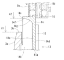
図3に示すように、放熱板14は、アルミニウム合金等の熱伝導性に優れた材料によって一体化されており、半径方向に延びる平板状に形成された底面部14aと、底面部14a上に形成された複数の冷却フィン14b(放熱用フィンに該当する)と、底面部14aに接続された遮蔽壁14cとを備えている。底面部14aの後面14d(一面に該当する)には、前述したパワーモジュール15が取り付けられている。
放熱板14は、中央部を回転軸5dが貫通するように、略C形状を呈しており、回転軸5dおよび給電ブラシ9a、9bを半径方向外方において取り囲んでいる。冷却フィン14bおよび遮蔽壁14cは、底面部14aの前面14e(他面に該当する)から回転軸方向前方に向けて突出している。底面部14a上において、冷却フィン14bは半径方向に放射状に延びている。遮蔽壁14cは底面部14a上を周方向に延びて、各々の冷却フィン14bの半径方向における内端部を互いに連結している(図2および図3示)。尚、底面部14aと冷却フィン14bとを含めた構成が、通風部に該当する。
As shown in FIG. 3, the
The
図4に示したように、遮蔽壁14cの半径方向外方に位置する面14fと、底面部14aの前面14eとの間には、所定半径を有した曲面部14gが設けられ、遮蔽壁14cと底面部14aとの接続部は滑らかな円弧状に形成されている。
また、図4に示したように、遮蔽壁14cの回転軸方向の突出量h1は、冷却フィン14bの回転軸方向の突出量h2よりも大きくなるように設定されている(h1>h2)。
図1に示したように、放熱板14は、給電ブラシ9a、9bを避けるように、第2ボデー3に取り付けられている。放熱板14は、リヤカバー11と第2ボデー3との間に形成された吸気口12に対し半径方向に対向しており、吸気口12を介して、放熱板14の外周部が交流発電機1の外方から視認可能に形成されている。放熱板14の遮蔽壁14cは、吸気口12と給電ブラシ9a、9bとの間に配置されている。
As shown in FIG. 4, a
Further, as shown in FIG. 4, the protrusion amount h1 of the shielding
As shown in FIG. 1, the
図5および図6に示すように、第2ボデー3には、放熱板14の前面14eに対して回転軸方向に対向する壁部3aを有している。壁部3aは、第1ボデー2、第2ボデー3およびリヤカバー11を包括したハウジング内を仕切っている。壁部3aには、吸気口12から進入した冷却空気が通過する複数の吸入窓3bが貫通している。また、第2ボデー3の外周面には、回転軸方向において、壁部3aに対する放熱板14の反対側に位置するように、空気排出孔3cが形成されている(図1示)。
図5に示したように、吸入窓3bの回転軸5dの回転中心からの最外径r1は、遮蔽壁14cの、回転軸5dの回転中心からの径r2よりも大きく設定されている(r1>r2)。すなわち、遮蔽壁14cは、吸入窓3bの最外径部よりも半径方向内方に位置している。
As shown in FIGS. 5 and 6, the
As shown in FIG. 5, the outermost diameter r1 from the rotation center of the
次に、交流発電機1の作動について説明する。直流電源から界磁コイル5cに電力が加えられた状態で、プーリー8を介して、エンジンによってローター5が回転されると、ステータコイル4bにおいて交流電力が発生する。ステータコイル4bにおいて発生した電力は、パワーモジュール15によって直流に変換される。パワーモジュール15によって直流に変換された電力は、必要な場合には、ICレギュレータによって適正な電圧に調整された後、直流電源に蓄えられる。
ローター5が駆動されることにより、リヤ冷却ファン6bが回転すると、吸気口12から冷却空気が吸引され、交流発電機1の内部に進入する。冷却空気は、吸入窓3bを通過して第2ボデー3内に進入した後、ステータコイル4bを冷却し、空気排出孔3cから外部へ排出される。吸気口12から進入した冷却空気が、冷却フィン14bに沿って放熱板14を通過する際に、パワーモジュール15によって発生された熱が放出される。尚、図1において、冷却空気の進入経路を太い矢印にて示している。
また、吸気口12から進入した冷却空気は遮蔽壁14cによって遮られ、給電ブラシ9a、9bへ到達することが阻止される。したがって、万が一、異物が吸気口12から交流発電機1の内部に進入したとしても、給電ブラシ9a、9bの摺動部に入り込むことがなく、冷却空気とともに空気排出孔3cから外部へ排出される。
Next, the operation of the AC generator 1 will be described. When the
When the
Further, the cooling air that has entered from the
本実施形態によれば、吸気口12と給電ブラシ9a、9bとの間には、進入した冷却空気が給電ブラシ9a、9bへ到達することを阻止する遮蔽壁14cが形成されている。これにより、進入した冷却空気が、遮蔽壁14cに遮られ、給電ブラシ9a、9bへ到達することがないため、冷却空気とともに異物が給電ブラシ9a、9bの摺動部に入り込むことがない。したがって、給電ブラシ9a、9bの磨耗や給電ブラシ9a、9bとスリップリング5e、5fとの間の接触不良を防止することができる。
また、放熱板14が一体的に形成され、半径方向に延びる平板状に形成された底面部14aの後面14dには、パワーモジュール15が固定されている。また、底面部14aの前面14eには、回転軸方向に突出した複数の冷却フィン14bが、半径方向に延びるように形成されている。また、遮蔽壁14cは、前面14eから回転軸方向に突出するとともに、周上に延びて複数の冷却フィン14bを互いに連結している。これにより、複数の冷却フィン14bおよび遮蔽壁14cを一つの成形工程によって容易に形成することができる。また、放熱板14を第2ボデー3に取り付けるだけで、交流発電機1内に冷却フィン14bおよび遮蔽壁14cを設けることができ、その取付工程を簡素化することができる。
また、放熱板14において、遮蔽壁14cが一体に形成されているため、遮蔽壁14c自体が放熱部として機能することにより、放熱板14全体の放熱面積を増大させることができる。
さらに、遮蔽壁14cを設けることにより放熱板14の剛性を増大させることができるため、剛性の低下を危惧することなく、冷却フィン14bを高くしたり、その枚数を増やしたりすることができる。したがって、放熱板14からの放熱効果をいっそう向上させることができる。
According to the present embodiment, the shielding
In addition, the
Further, since the shielding
Furthermore, since the rigidity of the
また、遮蔽壁14cの半径方向外方に位置する面14fと底面部14aの前面14eとの間に曲面部14gを設け、双方の接続部は、滑らかな円弧状に形成されている。これにより、吸気口12から第2ボデー3内に進入した冷却空気が放熱板14を通過する際の抵抗を低減し、放熱板14を通過する冷却空気の量の低下を防ぐことができる。したがって、パワーモジュール15の冷却効果をさらに向上させることができる。また、放熱板14を成形する際に、曲面部14gによって、冷却フィン14bの突出方向への型抜きが容易になり、成形型の耐久性も向上する。
また、遮蔽壁14cは、冷却フィン14bよりも回転軸方向に大きく突出していることにより、異物の給電ブラシ9a、9bとスリップリング5e、5fとの摺動部への進入を、さらに防止することができる。
また、遮蔽壁14cは、複数の冷却フィン14bの内端部を接続していることにより、進入した冷却空気が遮蔽壁14cに遮られることなく、冷却フィン14bの全体に行き渡る。このため、遮蔽壁14cの存在にかかわらず、半径方向に延びている冷却フィン14bの全体を有効に利用して放熱を行い、パワーモジュール15を冷却することができる。
Further, a
Further, the shielding
Further, since the shielding
また、第2ボデー3は、放熱板14の前面14eに対して回転軸方向に対向し、交流発電機1内を仕切る壁部3aを有している。また、壁部3aには、吸気口12から進入した冷却空気が通過する吸入窓3bが貫通している。また、第2ボデー3の外周面には、回転軸方向において、壁部3aに対する放熱板14の反対側に位置する空気排出孔3cが形成されている。これらにより、吸気口12から進入した冷却空気が、壁部3aに形成された吸入窓3bを通過した後、空気排出孔3cから外部に排出される。この時、遮蔽壁14cが吸入窓3bの最外径部よりも半径方向内方に位置しているため、遮蔽壁14cによりガイドされた冷却空気が壁部3aに衝突することなく、スムーズに吸入窓3b内を通過することができる。したがって、吸気口12から交流発電機1の内部に進入した冷却空気が、第2ボデー3の壁部3aを通過する際の抵抗が低減される。その結果、放熱板14を通過する冷却空気の量を増大させ、パワーモジュール15の冷却効果を向上させることができる。
また、遮蔽壁14cは複数の冷却フィン14bを内周側で連結するので、放熱板14の剛性を高めることができる。よって、冷却フィン14bを、欠けにくくすることができるので、製造段階での取り扱いが容易になり、製造コストの低減が可能となる。さらに、欠けにより生ずる可能性のある回転電機内部での短絡故障を防止する効果も高めることができる。
また、遮蔽壁14c自体が放熱部として機能することによる放熱面積増大効果と、冷却空気を軸方向へガイドする機能による冷却性能を向上させることができる。
Further, the
Further, since the shielding
Further, it is possible to improve the heat radiation area increasing effect due to the shielding
<他の実施形態>
本発明は、上述した実施形態に限定されるものではなく、次のように変形または拡張することができる。
本発明は、パワーモジュール15によって交流に変換された電力をステータ4に供給することにより、ローター5を駆動する電動機にも適用可能である。
また、本発明は、車両において使用する回転電機のみではなく、家庭電器用の回転電機または一般産業機械用の回転電機にも適用可能である。
また、遮蔽部14cは、必ずしも底面部14aに一体的に形成しなければならないわけではなく、遮蔽部14cを単体で第2ボデー3等に取り付けてもよい。
<Other embodiments>
The present invention is not limited to the above-described embodiments, and can be modified or expanded as follows.
The present invention can also be applied to an electric motor that drives the
The present invention can be applied not only to a rotating electrical machine used in a vehicle but also to a rotating electrical machine for home appliances or a rotating electrical machine for general industrial machines.
Moreover, the shielding
図面中、1は交流発電機(回転電機)、2は第1ボデー(ハウジング)、3は第2ボデー(ハウジング)、3aは壁部、3bは吸入窓、3cは空気排出孔、4はステータ、5はローター、5dは回転軸、5e,5fはスリップリング、9a,9bは給電ブラシ、11はリヤカバー(ハウジング)、12は吸気口(空気導入孔)、14は放熱板(素子取付部材)、14aは底面部(通風部)、14bは冷却フィン(放熱用フィン、通風部)、14cは遮蔽壁、14dは後面(一面)、14eは前面(他面)、14fは半径方向外方に位置する面、14gは曲面部、15はパワーモジュール(電力変換素子)を示している。 In the drawings, 1 is an AC generator (rotary electric machine), 2 is a first body (housing), 3 is a second body (housing), 3a is a wall portion, 3b is a suction window, 3c is an air discharge hole, and 4 is a stator. 5 is a rotor, 5d is a rotating shaft, 5e and 5f are slip rings, 9a and 9b are power supply brushes, 11 is a rear cover (housing), 12 is an intake port (air introduction hole), and 14 is a heat sink (element mounting member). , 14a is a bottom surface portion (ventilation portion), 14b is a cooling fin (heat radiation fin, ventilation portion), 14c is a shielding wall, 14d is a rear surface (one surface), 14e is a front surface (other surface), and 14f is radially outward. Positioned surface, 14g is a curved surface portion, and 15 is a power module (power conversion element).
Claims (6)
該ハウジングに固定されたステータ(4)と、
前記ハウジングに対して回転可能に取り付けられ、前記ステータに対して半径方向に対向したローター(5)と、
前記ハウジングに取り付けられ、前記ローターの回転軸(5d)に設けられたスリップリング(5e、5f)と摺接して前記ローターに電力を供給する給電ブラシ(9a、9b)と、
前記ステータに発生した電力を直流に変換する、または、前記ステータへの電力を交流に変換する電力変換素子(15)と、
該電力変換素子が取り付けられるとともに、放熱用フィン(14b)が形成され、前記ハウジングに取り付けられた通風部(14a、14b)と、
を備え、
前記ハウジングを貫通した空気導入孔(12)から前記ハウジング内に進入した冷却空気が、前記通風部を通過し、前記電力変換素子を冷却する回転電機(1)であって、
前記空気導入孔と前記給電ブラシとの間には、前記空気導入孔から進入した冷却空気が前記給電ブラシへ到達することを阻止する遮蔽壁(14c)が形成され、
前記通風部と前記遮蔽壁とが一体化されて素子取付部材(14)が形成され、
該素子取付部材は、
半径方向に延びる平板状に形成された底面部(14a)を有し、
該底面部の一面(14d)には前記電力変換素子が固定され、前記底面部の他面(14e)には前記遮蔽壁が回転軸方向に突出するように形成された回転電機。 Housings (2, 3, 11);
A stator (4) fixed to the housing;
A rotor (5) rotatably attached to the housing and radially opposed to the stator;
Power supply brushes (9a, 9b) that are attached to the housing and slidably contact slip rings (5e, 5f) provided on a rotation shaft (5d) of the rotor to supply electric power to the rotor;
A power conversion element (15) for converting electric power generated in the stator into direct current, or for converting electric power into the stator into alternating current;
The power conversion element is attached, and a heat radiating fin (14b) is formed, and ventilation portions (14a, 14b) attached to the housing;
With
Cooling air that has entered the housing through the air introduction hole (12) penetrating the housing passes through the ventilation section and cools the power conversion element (1),
Between the air introduction hole and the power supply brush, a shielding wall (14c) for preventing cooling air that has entered from the air introduction hole from reaching the power supply brush is formed ,
The ventilation portion and the shielding wall are integrated to form an element mounting member (14),
The element mounting member is
A bottom surface portion (14a) formed in a flat plate shape extending in the radial direction;
A rotating electrical machine in which the power conversion element is fixed to one surface (14d) of the bottom surface portion, and the shielding wall protrudes in the rotation axis direction on the other surface (14e) of the bottom surface portion .
前記底面部の前記他面に対して前記回転軸方向に対向し、前記ハウジング内を仕切る壁部(3a)を有し、
該壁部には、前記空気導入孔から進入した冷却空気が通過する吸入窓(3b)が貫通し、
前記ハウジングの外周面には、前記回転軸方向において、前記壁部に対する前記素子取付部材の反対側に空気排出孔(3c)が形成され、
前記遮蔽壁は、前記吸入窓の最外径部よりも半径方向内方に位置している請求項2乃至5のうちのいずれか一項に記載の回転電機。 The housing is
A wall portion (3a) that opposes the rotation axis direction with respect to the other surface of the bottom surface portion and partitions the inside of the housing;
A suction window (3b) through which the cooling air that has entered from the air introduction hole passes passes through the wall,
An air discharge hole (3c) is formed on the outer peripheral surface of the housing on the opposite side of the element mounting member with respect to the wall portion in the rotation axis direction.
The rotating electrical machine according to any one of claims 2 to 5, wherein the shielding wall is located radially inward from an outermost diameter portion of the suction window.
Priority Applications (2)
| Application Number | Priority Date | Filing Date | Title |
|---|---|---|---|
| JP2014137542A JP6213397B2 (en) | 2014-07-03 | 2014-07-03 | Rotating electric machine |
| DE102015110659.0A DE102015110659B4 (en) | 2014-07-03 | 2015-07-02 | ELECTRIC LATHE WITH COOLING MECHANISM |
Applications Claiming Priority (1)
| Application Number | Priority Date | Filing Date | Title |
|---|---|---|---|
| JP2014137542A JP6213397B2 (en) | 2014-07-03 | 2014-07-03 | Rotating electric machine |
Publications (2)
| Publication Number | Publication Date |
|---|---|
| JP2016015853A JP2016015853A (en) | 2016-01-28 |
| JP6213397B2 true JP6213397B2 (en) | 2017-10-18 |
Family
ID=54866359
Family Applications (1)
| Application Number | Title | Priority Date | Filing Date |
|---|---|---|---|
| JP2014137542A Expired - Fee Related JP6213397B2 (en) | 2014-07-03 | 2014-07-03 | Rotating electric machine |
Country Status (2)
| Country | Link |
|---|---|
| JP (1) | JP6213397B2 (en) |
| DE (1) | DE102015110659B4 (en) |
Families Citing this family (5)
| Publication number | Priority date | Publication date | Assignee | Title |
|---|---|---|---|---|
| FR3070802B1 (en) * | 2017-09-01 | 2020-07-17 | Valeo Equipements Electriques Moteur | ROTATING ELECTRIC MACHINE WITH HOLD OF THE SIMPLIFIED ELECTRONIC ASSEMBLY |
| JP7113913B2 (en) * | 2018-12-17 | 2022-08-05 | 三菱電機株式会社 | Rotating electric machine |
| JP6921265B1 (en) * | 2020-04-02 | 2021-08-18 | 三菱電機株式会社 | Control device integrated rotary electric machine |
| US12166400B2 (en) * | 2021-12-30 | 2024-12-10 | Regal Beloit Australia Pty Ltd | Electric machine including an air cooling system |
| WO2025189472A1 (en) * | 2024-03-15 | 2025-09-18 | Abb Schweiz Ag | Heat generation module and associated electrical device |
Family Cites Families (10)
| Publication number | Priority date | Publication date | Assignee | Title |
|---|---|---|---|---|
| JPH0461462U (en) | 1990-09-28 | 1992-05-26 | ||
| JPH0974718A (en) * | 1995-09-01 | 1997-03-18 | Asmo Co Ltd | Cooling-air introducing structure of automobile motor |
| JP3983445B2 (en) | 2000-03-15 | 2007-09-26 | 三菱電機株式会社 | AC generator |
| DE10041631A1 (en) * | 2000-08-24 | 2002-03-07 | Hilti Ag | Universal electric motor for power hand tool subjected to dust e.g. grinder, has protection screen made of stiff, thermally-conductive material |
| WO2006028981A2 (en) * | 2004-09-01 | 2006-03-16 | Remy International, Inc. | Electronic package for electrical machine |
| JP2006166538A (en) * | 2004-12-06 | 2006-06-22 | Hitachi Ltd | Rotating electric machine for vehicles |
| JP4402057B2 (en) * | 2006-02-21 | 2010-01-20 | 三菱電機株式会社 | Controller-integrated rotating electrical machine |
| JP4402712B2 (en) | 2007-11-16 | 2010-01-20 | 三菱電機株式会社 | Controller-integrated rotating electrical machine |
| JP5014445B2 (en) | 2010-02-10 | 2012-08-29 | 三菱電機株式会社 | Electric power supply unit integrated rotating electric machine |
| JP5807784B2 (en) | 2012-08-07 | 2015-11-10 | 株式会社デンソー | Power converter |
-
2014
- 2014-07-03 JP JP2014137542A patent/JP6213397B2/en not_active Expired - Fee Related
-
2015
- 2015-07-02 DE DE102015110659.0A patent/DE102015110659B4/en not_active Expired - Fee Related
Also Published As
| Publication number | Publication date |
|---|---|
| JP2016015853A (en) | 2016-01-28 |
| DE102015110659B4 (en) | 2023-06-22 |
| DE102015110659A1 (en) | 2016-01-07 |
Similar Documents
| Publication | Publication Date | Title |
|---|---|---|
| JP5542977B1 (en) | Rotating electric machine | |
| US9077230B2 (en) | Electric motor with heat dissipating device | |
| US20140292163A1 (en) | Electric motor with cooling apparatus | |
| JP6433585B2 (en) | AC generator for vehicles | |
| JP6379895B2 (en) | Rotating electric machine | |
| JP5368532B2 (en) | Electric power supply unit integrated rotating electric machine | |
| CN108141107B (en) | Electric motor | |
| JP5674900B1 (en) | Electric power supply unit integrated rotating electric machine | |
| JP6213397B2 (en) | Rotating electric machine | |
| JP5661167B1 (en) | Electric power supply unit integrated rotating electric machine | |
| CN105594102A (en) | motor | |
| JP4340305B2 (en) | Vehicle alternator | |
| JP2017085692A (en) | Inverter-integrated rotating electrical machine | |
| CN111869057B (en) | Rotating electric machine with brush | |
| US20060208581A1 (en) | Alternator | |
| JP5638701B2 (en) | Rotating electric machine | |
| JP4889517B2 (en) | Rotating electrical machine equipment | |
| JP6918242B2 (en) | Rotating machine | |
| JP2007336695A (en) | AC generator for vehicles | |
| JP2009303356A (en) | Rotating electrical machine | |
| EP3923455B1 (en) | Dynamo-electric machine | |
| JP2005102465A (en) | Generator motor coupled integrally with control unit | |
| CN108886300B (en) | Rotating electrical machine | |
| CN109923763B (en) | Protective cover for rotating electrical machines |
Legal Events
| Date | Code | Title | Description |
|---|---|---|---|
| A621 | Written request for application examination |
Free format text: JAPANESE INTERMEDIATE CODE: A621 Effective date: 20160909 |
|
| A131 | Notification of reasons for refusal |
Free format text: JAPANESE INTERMEDIATE CODE: A131 Effective date: 20170516 |
|
| A977 | Report on retrieval |
Free format text: JAPANESE INTERMEDIATE CODE: A971007 Effective date: 20170517 |
|
| A521 | Request for written amendment filed |
Free format text: JAPANESE INTERMEDIATE CODE: A523 Effective date: 20170630 |
|
| TRDD | Decision of grant or rejection written | ||
| A01 | Written decision to grant a patent or to grant a registration (utility model) |
Free format text: JAPANESE INTERMEDIATE CODE: A01 Effective date: 20170822 |
|
| A61 | First payment of annual fees (during grant procedure) |
Free format text: JAPANESE INTERMEDIATE CODE: A61 Effective date: 20170904 |
|
| R151 | Written notification of patent or utility model registration |
Ref document number: 6213397 Country of ref document: JP Free format text: JAPANESE INTERMEDIATE CODE: R151 |
|
| R250 | Receipt of annual fees |
Free format text: JAPANESE INTERMEDIATE CODE: R250 |
|
| R250 | Receipt of annual fees |
Free format text: JAPANESE INTERMEDIATE CODE: R250 |
|
| R250 | Receipt of annual fees |
Free format text: JAPANESE INTERMEDIATE CODE: R250 |
|
| R250 | Receipt of annual fees |
Free format text: JAPANESE INTERMEDIATE CODE: R250 |
|
| LAPS | Cancellation because of no payment of annual fees |