JP6213248B2 - Electronics - Google Patents
Electronics Download PDFInfo
- Publication number
- JP6213248B2 JP6213248B2 JP2014005478A JP2014005478A JP6213248B2 JP 6213248 B2 JP6213248 B2 JP 6213248B2 JP 2014005478 A JP2014005478 A JP 2014005478A JP 2014005478 A JP2014005478 A JP 2014005478A JP 6213248 B2 JP6213248 B2 JP 6213248B2
- Authority
- JP
- Japan
- Prior art keywords
- component
- functional
- support
- functional component
- case
- Prior art date
- Legal status (The legal status is an assumption and is not a legal conclusion. Google has not performed a legal analysis and makes no representation as to the accuracy of the status listed.)
- Expired - Fee Related
Links
- 230000002093 peripheral effect Effects 0.000 claims description 15
- 238000003780 insertion Methods 0.000 claims description 3
- 230000037431 insertion Effects 0.000 claims description 3
- 230000010365 information processing Effects 0.000 description 15
- 238000009434 installation Methods 0.000 description 10
- 239000000758 substrate Substances 0.000 description 7
- 238000000034 method Methods 0.000 description 4
- 230000005484 gravity Effects 0.000 description 3
- 239000002184 metal Substances 0.000 description 3
- 238000012986 modification Methods 0.000 description 3
- 230000004048 modification Effects 0.000 description 3
- 239000011347 resin Substances 0.000 description 3
- 229920005989 resin Polymers 0.000 description 3
- 239000000853 adhesive Substances 0.000 description 2
- 230000001070 adhesive effect Effects 0.000 description 2
- 238000001514 detection method Methods 0.000 description 2
- 230000000694 effects Effects 0.000 description 2
- 238000011900 installation process Methods 0.000 description 2
- 239000007769 metal material Substances 0.000 description 2
- 230000008569 process Effects 0.000 description 2
- 230000004913 activation Effects 0.000 description 1
- 230000015572 biosynthetic process Effects 0.000 description 1
- 230000000903 blocking effect Effects 0.000 description 1
- 210000000078 claw Anatomy 0.000 description 1
- 238000007306 functionalization reaction Methods 0.000 description 1
- 230000017525 heat dissipation Effects 0.000 description 1
- 239000004973 liquid crystal related substance Substances 0.000 description 1
- 239000000463 material Substances 0.000 description 1
- 238000012544 monitoring process Methods 0.000 description 1
- 230000003287 optical effect Effects 0.000 description 1
- 238000012545 processing Methods 0.000 description 1
- 230000004044 response Effects 0.000 description 1
Images


Classifications
-
- Y—GENERAL TAGGING OF NEW TECHNOLOGICAL DEVELOPMENTS; GENERAL TAGGING OF CROSS-SECTIONAL TECHNOLOGIES SPANNING OVER SEVERAL SECTIONS OF THE IPC; TECHNICAL SUBJECTS COVERED BY FORMER USPC CROSS-REFERENCE ART COLLECTIONS [XRACs] AND DIGESTS
- Y02—TECHNOLOGIES OR APPLICATIONS FOR MITIGATION OR ADAPTATION AGAINST CLIMATE CHANGE
- Y02E—REDUCTION OF GREENHOUSE GAS [GHG] EMISSIONS, RELATED TO ENERGY GENERATION, TRANSMISSION OR DISTRIBUTION
- Y02E60/00—Enabling technologies; Technologies with a potential or indirect contribution to GHG emissions mitigation
- Y02E60/10—Energy storage using batteries
Landscapes
- Position Input By Displaying (AREA)
- Battery Mounting, Suspending (AREA)
Description
本開示の技術は、機能部品を支持する支持部品を備えた電子機器に関する。
The technology of the present disclosure relates to an electronic device including a support component that supports a functional component.
電子機器のケース内に収納される機能部品は、たとえばケースに対して直接固定されるほか、支持部品を介在させて固定されるものがある。支持部品は、たとえば支持対象である機能部品の位置固定など、収納状態の安定化を図るために用いられる。電子機器は、機能部品の設置にネジなどの固定部品を利用するものや、機能部品の一部をケースや支持部品に係合させて支持させるものがある。 For example, functional parts housed in a case of an electronic device are not only directly fixed to the case but also fixed via a support part. The support component is used to stabilize the storage state, for example, to fix the position of the functional component to be supported. Some electronic devices use fixed parts such as screws for installation of functional parts, and others support parts by engaging a part of the functional parts with a case or a supporting part.
このような電子機器に対する機能部品の設置に関し、たとえば筐体に付勢されたバネにより筐体にバッテリが固定されるとともに、このバッテリと係合してロック状態を維持し、または解除させるフックを備えるものが知られている(例えば、特許文献1)。シールド部材のフランジ部の突出部分を取付板金の鉤型の係止部の下方側から挿入させることで突出部分が係止部に係止されるものが知られている(例えば、特許文献2)。また、バッテリユニットの外装筐体の周縁側にフランジが形成され、このフランジを電子機器の筐体の溝内に挿入して設置されるものが知られている(例えば、特許文献3)。 Regarding the installation of functional parts for such an electronic device, for example, a battery is fixed to the housing by a spring biased by the housing, and a hook that engages with the battery to maintain or release the lock is provided. What is provided is known (for example, Patent Document 1). It is known that the protruding portion is locked to the locking portion by inserting the protruding portion of the flange portion of the shield member from the lower side of the hook-shaped locking portion of the mounting sheet metal (for example, Patent Document 2). . In addition, it is known that a flange is formed on the peripheral side of the outer casing of the battery unit, and the flange is inserted into a groove of the casing of the electronic device (for example, Patent Document 3).
ところで、電子機器は、薄型化や小型化によりケース内部に対する機能部品の収納エリアが減少するとともに、多機能化による部品数の増加により収納スペースが狭小化しており、内蔵される機能部品の小型化や収納状態のコンパクト化が要求されている。 By the way, electronic devices have a reduced storage area for functional parts inside the case due to thinning and miniaturization, and an increase in the number of parts due to multi-functionalization has reduced the storage space. There is also a demand for compact storage.
携帯電話機やノート型PC(Personal Computer)などの電子機器は、たとえばケース内に搭載される機能部品として、外出時や移動中に使用するためバッテリ(Battery)が内蔵されている。多機能化した電子機器は、電力の消費量が増加するとともに、長時間の動作が要求されていることから、搭載するバッテリの容量を大きくする必要がある。しかしバッテリは、たとえば内部に収納されるバッテリセルの大きさや数によって容量の多少が決まるが、収納スペースが限られていることから幅方向の投影面積を小型化できない。そのほか電子機器には、たとえば構成部品を機能させるために必要な大きさや対応するメディアなどの大きさなどにより、投影面積を小型化できない機能部品を備える。 Electronic devices such as mobile phones and notebook PCs (Personal Computers) have built-in batteries for use when they are out or on the move, for example, as functional components mounted in a case. Multifunctional electronic devices are required to increase the capacity of a battery to be mounted because power consumption increases and long-time operation is required. However, the capacity of the battery is determined depending on, for example, the size and number of battery cells housed therein, but the projection area in the width direction cannot be reduced because the storage space is limited. In addition, the electronic device is provided with a functional component whose projection area cannot be reduced due to, for example, the size required to make the component function or the size of the corresponding media.
これらの機能部品は、収納スペース内において周辺に設置された他の機能部品と近接し、または上下方向に重ねてケース内に収納することになるが、接触による干渉を回避する必要があり、ケースに対して固定部品による固定位置が限られるという課題がある。 These functional parts are stored in the case close to other functional parts installed in the vicinity in the storage space, or stacked in the vertical direction, but it is necessary to avoid interference due to contact. However, there is a problem that the fixing position by the fixing component is limited.
また、バッテリなどの大型の機能部品は、外装面に接触して支持する取付金具などを利用するものがあるが、荷重負荷が大きいことからケースに対する支持強度が要求される。しかし、支持部品は、たとえばケースに対する固定位置よりも外側に機能部品からの荷重が作用すると、所謂片持ち梁状態となり、支持強度が十分に得られなくなるおそれがあるという課題がある。 In addition, some large functional parts such as batteries use mounting brackets that are in contact with and support the exterior surface. However, since the load is large, the support strength for the case is required. However, for example, when the load from the functional component acts outside the fixed position with respect to the case, the support component is in a so-called cantilever state, and there is a problem that sufficient support strength may not be obtained.
そこで、本開示の技術は、上記課題に鑑み、機能部品同士の干渉を回避するとともに実装高さを抑え、電子機器の薄型化を図ることを第1の目的とする。 Therefore, in view of the above-described problems, the first object of the technology of the present disclosure is to avoid interference between functional components and reduce the mounting height, thereby reducing the thickness of the electronic device.
また、本開示の技術は、機能部品の支持強度を向上させることを第2の目的とする。
Moreover, the technique of this indication makes it the 2nd objective to improve the support strength of a functional component.
上記目的を達成するため、本開示の構成の一側面は、機能部品を内部に収納するケースと、支持部品とを備える。支持部品は、胴体部と該胴体部の両端側に前記胴体部と高さを異ならせて形成した第1及び第2の切片部とを備え、前記ケースに収納される第1の機能部品を前記胴体部に載置させて支持する一面側に対し、その背面側に第2の機能部品に形成された固定部と係合する係合部が前記第1の切片部に形成され、前記第1及び第2の切片部に前記第2の機能部品を載置して支持する。そして、前記支持部品は、前記第1の切片部の外周側の、前記第1の機能部品と前記第2の機能部品のいずれも載置しない位置に、前記胴体部から離間する方向に向けて突出部が形成され、該突出部が前記ケースに固定される。
In order to achieve the above object, one aspect of the configuration of the present disclosure includes a case that accommodates a functional component therein and a support component. The support component includes a body portion and first and second sections formed at different heights from the body portion on both ends of the body portion, and the first functional component housed in the case An engaging portion that engages with a fixing portion formed on the second functional component on the back surface side is formed on the first section portion with respect to the one surface side that is placed on and supported by the body portion . The second functional component is placed and supported on the first and second sections . And the said support component is in the direction which leaves | separates from the said trunk | drum part in the position which neither the said 1st functional component nor the said 2nd functional component is mounted in the outer peripheral side of the said 1st interception part. A protrusion is formed, and the protrusion is fixed to the case.
本開示の技術によれば、次のいずれかの効果が得られる。 According to the technique of the present disclosure, any of the following effects can be obtained.
(1) 電子機器内における実装高さを抑えることができ、電子機器の薄型化を図ることができる。 (1) The mounting height in the electronic device can be suppressed, and the electronic device can be thinned.
(2) 積層した機能部品に対する支持強度を確保することができる。
(2) Support strength for the laminated functional parts can be secured.
〔第1の実施形態〕 [First Embodiment]
図1は、第1の実施の形態に係る電子機器について、機能部品の実装状態例を示している。 FIG. 1 shows an example of a mounted state of functional components for the electronic apparatus according to the first embodiment.
電子機器2は、本開示の電子機器の一例であり、たとえば図1に示すように電子機器を機能させる多数の機能部品の一部として機能部品4、6がケース8内に収納される。電子機器2は、たとえばPCや携帯電話機などの情報処理装置であり、ケース8の内部に機能部品4、6のほか図示しない多数の機能部品を備えている。機能部品4、6は、たとえばケース8内において近接して配置され、ともに支持部品10に載置されることで一体化して支持される。支持部品10は、本開示の支持部品の一例である。
The
支持部品10は、たとえば両面側に機能部品を載置可能な板状であり、金属材料や樹脂材料で形成されている。この支持部品10は、たとえばケース8内において電子機器2の設置状態に対して機能部品4、6を水平状態に実装させるように、両面に載置面12、18が形成される。載置面18は、第1の機能部品の一例である機能部品4を接触させて支持する。機能部品4は、たとえば図示しない固定手段や接着手段を介して載置面18に上面部分を固定されてもよい。載置面12は、載置面18の背面側に形成され、ケース8内に形成される収納エリアの内部側に本開示の第2の機能部品の一例である機能部品6を接触させて支持する。これによりケース8の収納領域に対し、機能部品4、6を積層状態で配置してもケース8や図示しない他の機能部品に接触させない。
The
載置面12には、機能部品6の一部に形成された固定部の一例である突起部14に係合させるフック16が形成されている。このフック16は本開示の係合部の一例であり、たとえば載置面12に載置された機能部品6が上方に離間するのを阻止するように突起部14に係合させる。このフック16は、積層させる機能部品6の突起部14の形成位置および形成数に応じて形成される。
A
載置面12、18の幅や長さは、実装される機能部品4、6の幅や長さに応じて設定され、またはケース8内に実装される図示しない他の機能部品に対して接触しない大きさに設定される。
The width and length of the
支持部品10は、機能部品4、6の積層部分よりも外周側に突出部22が形成される。この突出部22は、機能部品4、6のいずれも載置させない位置に形成される。また、突出部22は、先端部分の一部がケース8の一部に載置させる長さや幅に形成される。突出部22は、たとえば載置させるケース8の高さや、支持部品10の近傍に配置される図示しない基板や他の実装部品に接触しない高さ、または載置面12、18と同等の高さで形成してもよい。
In the
そして突出部22は、ケース8に対して載置された部分に対し固定部品24が挿通されてケース8に固定される。そのほか支持部品10は、たとえば突出部22を含む周縁部分において、図示しない固定部品によりケース8や近接した他の機能部品などに固定される。これにより支持部品10は、突出部22においてケース8に締結されることで、機能部品4、6の積層部分よりも外周側で固定でき、フック16側の面に対する支持強度を向上させることができる。また、機能部品4、6に対する積層位置から離間して固定部品24を係合させることで、固定部品24と機能部品4、6とが積層状態で配置されるのを回避でき、支持部品10に対する機能部品4、6の積層高さを抑えられる。
The protruding
図2は、電子機器2に対する機能部品の実装状態の一例を示している。
FIG. 2 shows an example of the mounting state of the functional components on the
電子機器2は、たとえばケース8の収納面側に対し、設定された位置に機能部品4が設置される。ケース8には、たとえば機能部品4を嵌合させて、外装の一面側を外部または他の収納エリア側に露出させる開口部20が形成される。支持部品10は、載置面18をケース8側に向け、開口部20に設置される機能部品4の上面側に接触させる。
In the
支持部品10は、たとえば載置面18が形成される部分の周縁側に、載置面18と高さの異なる複数の切片部38、39が形成されている。この切片部38、39には、載置面18の背面側に載置面12が形成される。切片部38は、載置面18と接続された一辺に対して反対側の辺に突出部22が接続されている。切片部38は、たとえば載置面18または突出部22に対して交差方向に、載置面18よりも幅広に形成されており、その両端側に固定部品24によりケース8または他の機能部品などに固定させる支持孔40が形成される。
In the
切片部38は、たとえば載置面18より外側の位置にフック16が形成される。フック16は、たとえば切片部38の両側に形成されており、フック16間の距離が載置面18の横幅または機能部品4の横幅よりも大きく設定される。フック16は、たとえば載置面12に対して平行に形成されており、機能部品6の突起部14を載置面12に対して平行状態で係合させる。またフック16は、載置面12を形成する部品側に向けて開口している。フック16は、突出部22の突出方向と反対側に開口しており、載置面12上に載置される機能部品6の設置位置を制限している。すなわち、フック16は、載置面12と突出部22との間で上方に突出することで、機能部品6が突出部22側に積層されるのを阻止するとともに、載置された機能部品6が突出部22にスライドするのを阻止する。
In the
切片部39は、たとえば載置面18から離間する方向に一定幅で形成され、その先端側に固定部品24を挿通させる支持孔40が形成される。
For example, the
支持部品10は、支持孔40を通じて挿通された固定部品24によりケース8の設置面側に固定される。ケース8には、固定部品24と締結させるネジ孔を備えたスタッド(Stud)42が形成される。
The
なお、支持部品10を固定する固定部品24は、たとえばネジ部品のほか、ラッチ部品などを利用してもよく、または接着材や熱により溶着させる部材を利用してもよく、または溶接してもよい。突出部22は、支持部品10の一辺側にのみ形成されるものに限られず、載置面12、18の外周側に複数形成されてもよい。突出部22は、周縁に配置される図示しない基板やフレキシブルケーブルなどの機能部品を回避させる形状に形成される。
The fixing
機能部品6は、たとえば一辺側に突起部14が形成され、突起部14が形成された辺以外の辺に固定部品32に挿通させる支持部30が形成される。この支持部30は、挿通させた固定部品32によって機能部品6を支持させる支持孔を備えている。支持部30は、機能部品6の側面側であって、機能部品4や支持部品10との積層部分に固定部品32が接触しない位置に形成される。支持部30に挿通された固定部品32は、たとえばケース8や他の機能部品、基板34などに形成される孔36に挿通されて固定される。
In the
斯かる構成によれば、支持部品10の両面側に複数の機能部品4、6を支持させることで電子機器2内における実装高さを抑えることができ、電子機器2の薄型化を図ることができる。支持部品10により機能部品4、6を面で支持するとともに、支持部品10が突出部22において機能部品4、6の支持部分よりも外周側でケース8に固定されるので、積層した機能部品4、6に対する支持強度を確保することができる。
According to such a configuration, the mounting height in the
〔第2の実施の形態〕 [Second Embodiment]
図3、図4および図5は、第2の実施の形態に係る電子機器の一例を示している。図3、図4および図5に示す構成は一例であり、本開示の技術が係る構成に限定されない。 3, 4, and 5 illustrate an example of an electronic device according to the second embodiment. The configuration illustrated in FIGS. 3, 4, and 5 is an example, and is not limited to the configuration according to the technology of the present disclosure.
情報処理装置50は、本開示の電子機器の一例であり、たとえば図3に示すように、表示側筐体52、操作側筐体54がヒンジ56を介して開閉可能に連結されている。表示側筐体52には、たとえば表示モニタ58に映像や文字などの画像が表示される。表示モニタ58は、たとえばLCD(Liquid Crystal Display)表示部などが設置される。また、表示モニタ58には、たとえばユーザの生体指の接触により入力操作が可能なタッチパネルを備えてもよい。
The
操作側筐体54には、たとえばケース内に操作ボタン60やキーボードユニット62、タッチパッドユニット64などが搭載される。タッチパッドユニット64は、ユーザの指などの接触に応じて表示モニタ58に表示されるカーソル操作や押下によるクリック操作などを行うことができる機能部品の一例である。そのほか操作側筐体54には、情報処理装置50の起動状態や記憶部の読み出し処理や書き出し処理状態などを表示する、図示しない表示ランプなどを備えてもよい。
For example,
操作側筐体54は、たとえば図4に示すように、折り畳まれた表示側筐体52と対向するフロントカバー70と情報処理装置50の底面部分に配置されるリアカバー68が接合される。接合されたフロントカバー70およびリアカバー68は、本開示のケースの一例であり、情報処理装置50を機能させるコンピュータ構成部品などを収納する収納部を形成する。リアカバー68には、たとえば放熱用の開口部72のほか、フロントカバー70との間で締結される固定部品76(図5)を設置する開口部などが形成される。そのほか、操作側筐体54には、側面側にコネクタ部74のほか、ODD(Optical Disk Drive)装置などが設置される。
For example, as shown in FIG. 4, the operation-
<機能部品の実装状態について> <About the mounting state of functional parts>
操作側筐体54には、たとえば図5に示すように、フロントカバー70側に多数の機能部品が実装され、または接続されたプリント基板80、82やドライブ装置などが収納されている。また操作側筐体54には、プリント基板80に形成された開口部84に対して既述のタッチパッドユニット64が設置される。このタッチパッドユニット64は、本開示の第1の機能部品の一例であり、背面側にタッチパッドユニット64を支持する支持部品92が配置される。プリント基板80の開口部84は、タッチパッドユニット64の操作面を操作側筐体54の前面側に露出させるために形成されており、例えばタッチパッドユニット64の外形形状および大きさに合わせて形成される。また、フロントカバー70には、開口部84と同等の大きさの図示しない開口部が形成される。タッチパッドユニット64は、たとえば開口部84やフロントカバーの開口部に対して嵌合させて設置されればよい。
For example, as shown in FIG. 5, the operation-
支持部品92は、たとえば金属材料で形成され、タッチパッドユニット64の背面部分に接触し、一体化して支持する。支持部品92は、たとえば操作側筐体54の背面側からネジなどの固定部品32によりフロントカバー70に固定される。
The
<バッテリユニット94について>
<About the
操作側筐体54には、情報処理装置50の給電手段としてバッテリユニット94が搭載される。このバッテリユニット94は、本開示の第2の機能部品の一例であり、タッチパッドユニット64を支持する支持部品92の背面側に平面部分の一部または全部を接触させ、一体化して支持される。バッテリユニット94は、たとえば図6に示すように、内部にバッテリセルが収納され、一定の厚さの樹脂製のケースで形成されている。バッテリユニット94は、設定される容量に応じて内部のセルの数や大きさが増加する。このバッテリユニット94は、たとえば操作側筐体54を薄型化するため、設定容量に応じて幅方向の大きさが設定される。
A
バッテリユニット94は、たとえば長辺の一辺側を突出させた凸形状で形成されており、この突出した部分に図示しない端子部品が設置されている。またこの突出側の辺には、バッテリユニット94の外縁側に固定部品32を挿通させる支持孔を備えた支持片98が形成される。この支持片98は、支持部品92による支持のほか、周面側に挿通させた固定部品32によりフロントカバー70やフロントカバー70に設置された図示しない他の支持部品などに固定される。バッテリユニット94の長辺側には、本開示の固定部の一例である突起片96が形成されている。この突起片96は、たとえば長辺に対して直交方向に平板部97を突出させており、その両端側に一定の幅を持たせて対向した立壁部99が形成されている。平板部97は、バッテリユニット94の本体部分の底面部分に平行に突出している。
The
<タッチパッドユニット64と支持部品92について>
<About the
タッチパッドユニット64は、たとえば図7に示すようにフロントカバー70側に向けて配置される面にユーザの指に接触させるセンサパッド112が設置されるとともに、セッサパッド112の長辺側に、クリック操作を行うクリックボタン116が配置される。タッチパッドユニット64の背面側には、たとえばセンサパッド112による検出状態の監視機能やクリックボタン116の押下検出機能などを含む基板114が設置される。これらの基板114には、たとえばケーブル118が設置され、図示しないプリント基板80と電気的に接続される。
In the
支持部品92は、たとえばタッチパッドユニット64の背面側に接触する胴体部101と、その両端側に高さを異ならせて形成し、バッテリユニット94を載置させる切片部103、106を備えている。この切片部103、106は、同等の高さの平板状に形成され、バッテリユニット94に対する載置面100となる。胴体部101は、たとえば平板状に形成されるとともに、その平板部分の一部に基板114の実装部品との接触を回避するための開口部105が形成される。また胴体部101は、平板部分の両端側に載置面100と同等の高さ、またはそれよりも低い立壁部102が形成される。胴体部101は、たとえば立壁部102と切片部103、106との間にタッチパッドユニット64の一部を収納する収納部104を形成し、載置されたバッテリユニット94を基板114の実装部品に接触させないように形成される。
The
切片部103は、たとえば胴体部101側からの幅が、載置されたバッテリユニット94の外形部分から突出しないように設定されている。切片部103は、バッテリユニット94のコネクタが形成された突出部分またはその近傍を支持するため、載置されるバッテリユニット94の平板部分によって覆われる大きさで形成してコネクタ部分に接触させないように形成される。
For example, the
切片部106は、たとえば胴体部101の長辺よりも幅広であり、両端側を延伸させた翼形状で形成され、翼端側の一部に、載置面100に対して「コ」字状に立設させたフック108が形成される。フック108は、たとえば載置面100に対して平行にスライドさせたバッテリユニット94の突起片96を係止させる。そしてフック108は、上面部分で突起片96の平板部97に接触することで、設置されたバッテリユニット94が高さ方向に変位するのを阻止する。またフック108の立壁部分は、たとえば載置面100上でバッテリユニット94が平面方向へスライドした場合でも、平板部97に接触するとともに、突起片96を立壁部99に接触させることで、バッテリユニット94に対するストッパとして機能する。
The
支持部品92には、たとえば切片部106の一辺側に、胴体部101から離間する方向に向けて突出部110が形成される。突出部110は、フック108の立壁側よりも背面側に形成されており、バッテリユニット94やタッチパッド64に対して積層させない位置に形成される。この突出部110は、載置面100よりも外周側において固定部品24(図5)によりフロントカバー70などに固定される。突出部110は、たとえば三角形状に形成されており、切片部106との連結部分の剛性をもたせるとともに、情報処理装置50内部における面積が小さくなるように形成されている。
In the
<操作側筐体54に対する支持部品92の設置状態について>
<About the installation state of the
情報処理装置50には、たとえば図8に示すようにプリント基板80の開口部84内にタッチパッドユニット64が配置され、その背面側から支持部品92が載置される。支持部品92は、たとえば切片部103、106に形成された支持孔を通じて固定部品24が挿通され、フロントカバー70や図示しない金属部品に固定される。支持部品92は、突出部110の頂角側で固定部品24により固定される。これら固定部品24による固定位置は、たとえば支持部品92の各辺にそれぞれ設置され、略左右対称に固定される。
In the
支持部品92の切片部103、106は、一部がプリント基板80に対して一定の間隔をもって対向状態に配置されている。また切片部106に形成されたフック108は、プリント基板80と対向する位置であって、プリント基板80と接触させないように離間して形成される。
A part of the
またフロントカバー70には、たとえばヒンジ56側にプリント基板80と隣接した他のプリント基板82が収納されており、このプリント基板82上にバッテリユニット94と電気的に接続させるコネクタ120が実装されている。このプリント基板82は、たとえばバッテリユニット94から供給される電力の制御や各機能部品に供給する給電制御部やプロセッサなどを実装している。支持部品92に形成されるフック108は、たとえば「コ」字形状の開口部分が、端子部品の一例であるコネクタ120の挿入方向に対して対向するように形成される。これにより、バッテリユニット94は、コネクタ120による接続部分に対して離間した反対側の辺がフック108によって支持され、コネクタ120に対する重力方向への負荷が軽減される。
The
フロントカバー70に実装されたバッテリユニット94は、たとえば図9に示すように、支持部品92の胴体部101や切片部103を覆うとともに、プリント基板80の一部に重なっている。このときバッテリユニット94の背面部分は、たとえば支持部品92の載置面100に面接触して支持され、プリント基板80の実装部品に接触しない。
For example, as shown in FIG. 9, the
バッテリユニット94の実装作業では、たとえば支持部品92上に配置された後にコネクタをプリント基板82のコネクタ120側に接続させる。このとき、バッテリユニット94は、たとえば長辺側に形成された突起片96をフック108の上部側に載置させてもよい。コネクタ接続されたバッテリユニット94は、たとえばコネクタ120側に向けて押圧し、突起片96がフック108を回避させながら載置面100側に載置される。そして、突起片96は、コネクタ120側への押圧を解除することで載置面100をスライドしてフック108に係合させてもよい。また、バッテリユニット94は、フック108に載置した状態で支持部品92側に押圧させ、フック108を弾性変形させることで載置面100側に設置させてもよい。
In the mounting operation of the
このように、支持部品92は、バッテリユニット94の一辺側についてフック108により係合支持させることで、組立て作業の簡略化や固定部品24を削減することができる。
As described above, the
支持部品92は、たとえば図10に示すように胴体部101側の一面でタッチパッドユニット64を支持し、切片部103、106の一面で反対側にバッテリユニット94を積層状態で一体化して支持する。このとき、タッチパッドユニット64とバッテリユニット94は、立壁部102により離間しており、物理的な干渉を回避することができる。また、支持部品92は、たとえばユーザ操作によりセンサパッド112やクリックボタン116への押圧に対してバッテリユニット94のケースにより載置面100が支持され、支持剛性が得られる。
For example, as shown in FIG. 10, the
<操作側筐体54内の実装状態について>
<About the mounting state in the
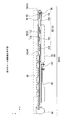
図11、図12、図13、図14は、操作側筐体内部の実装状態を示す断面図である。 11, 12, 13, and 14 are cross-sectional views showing the mounting state inside the operation-side casing.
支持部品92は、たとえば図11に示すように、バッテリユニット94から離間した突出部110がフロントカバー70に対して直接固定されることでバッテリユニット94の荷重による重力(−Y方向)に対して対抗している。これにより支持部品92は、たとえば突出部110の固定により剛性が維持されるので、一端側が変位し、または歪みが生じないので、支持するタッチパッドユニット64やバッテリユニット94の実装位置を維持させ、他の機能部品と接触させることがない。
For example, as shown in FIG. 11, the
支持部品92は、突出部110の一部を下方側に屈曲させ、突出高さを調整する段差部130が形成されている。この段差部130は、フロントカバー70に実装されたプリント基板80に対して高さ方向への突出を回避させるために形成される。すなわち、支持部品92の切片部106は、フロントカバー70に対する実装高さをプリント基板80の実装高さに近づけるとともに、突出部110とプリント基板80とが干渉させないように配置高さを調整している。したがって段差部130は、たとえば突出部110を固定するフロントカバー70の位置や近傍に設置される他の機能部品との高低に応じて高さが設定されればよい。
The
そして支持部品92は、胴体部101においてフロントカバー70に露出させたタッチパッドユニット64を支持するとともに、背面側の切片部103においてバッテリユニット94を支持する。
The
支持部品92は、図12に示すように、バッテリユニット94の一端側に形成された突起片96の平板部97に対してフック108を係合させることで重力方向(−Y方向)への変位を阻止している。
As shown in FIG. 12, the
バッテリユニット94は、図13に示すように、突起片96(図6)が形成された辺に対して反対側の辺において、外装側に形成された支持片98に挿通された固定部品32によりプリント基板82側に固定される。
As shown in FIG. 13, the
これにより支持部品92は、図14に示すように、フロントカバー70内の近傍に設置されたプリント基板80に対してバッテリユニット94を接触させずに支持するとともに、フロントカバー70に対する突出部110の固定により、支持剛性を維持している。
As a result, as shown in FIG. 14, the
<第2の実施の形態の効果> <Effects of Second Embodiment>
(1) 支持部品92の両面側に積層状態でバッテリユニット94やタッチパッドユニット64を支持させることで情報処理装置50内における実装高さを抑えることができ、情報処理装置50の薄型化を図ることができる。
(1) The mounting height in the
(2) 支持部品92によりバッテリユニット94やタッチパッドユニット64が面で支持され、支持機能を高められる。
(2) The
(3) 支持部品92が突出部110においてバッテリユニット94やタッチパッドユニット64の支持部分よりも外周側でフロントカバー70に固定されることで支持強度を確保し、バッテリユニット94の荷重などによる撓みや変形を防止する。
(3) The
(4) 支持部品92によりバッテリユニット94やタッチパッドユニット64の配置高さや設置位置を維持させることで、周囲に配置されるプリント基板80、82や他の機能部品との干渉を回避でき、情報処理装置50の機能安定性を確保して信頼性を高めることができる。
(4) By maintaining the arrangement height and installation position of the
(5) フック108と突起片96による係合構造により、支持部品92に対するバッテリユニット94の位置決め作業の簡易化や固定部品の削減による組立て作業の簡略化が図れる。
(5) Due to the engagement structure of the
以上説明した実施の形態について、変形例を以下に列挙する。 Examples of modifications described above are listed below.
(1) 上記実施の形態では、支持部品92によって支持される機能部品として、バッテリユニット94の外装側に支持片98や突起片96が形成される場合を示したがこれに限られない。情報処理装置50は、たとえば図15に示すように、支持部品92の載置面100上にバッテリユニット140が支持されている。このバッテリユニット140は、たとえば一辺側に形成された支持片98に固定部品32が挿入されてプリント基板82などに固定されるとともに、長辺側に備えた突起片96によって支持部品92のフック108に係合して支持される。
(1) In the above embodiment, the case where the
バッテリユニット140は、たとえば図16に示すように、本開示の電子部品であるバッテリセルやその他の部品が樹脂性の筐体によって覆われたバッテリ部品142と、このバッテリ部品142を収納する収納ケース144が含まれる。バッテリ部品142は、たとえば一辺側にコネクタなどが搭載されており、プリント基板82のコネクタ120に接続されて給電する。バッテリ部品142は、たとえば情報処理装置50の専用部品に限られず、他の情報処理装置に搭載されるバッテリ部品であってもよい。
For example, as shown in FIG. 16, the
収納ケース144は、バッテリ部品142を収納して支持する本開示の支持ケースの一例であり、バッテリ部品142を載置する載置部の周囲にバッテリ部品142の周縁を覆う壁部146が立設されている。また収納ケース144は、たとえば上面側が開放されており、バッテリ部品142の着脱が可能に形成されるほか、壁部146の一部にバッテリ部品142の図示しないコネクタを配置させる開口部148が形成されている。
The
収納ケース144は、たとえば壁部146によって形成される収納エリアの形状が挿入されるバッテリ部品142の外形形状と同等に形成され、収納エリア内部にバッテリ部品142が嵌合される。従って、バッテリ部品142が他の形状である場合、収納ケース144は、たとえばコネクタを挿通させる開口部148の位置を基準に、バッテリ部品142に合わせて形成されればよい。
The
収納ケース144は、たとえば開口部148が形成された辺に対して反対側の辺の外周側に、平板部97や立壁部99を含む突起片96が形成される。そのほか、収納ケース144は、たとえば壁部146の内側に、配置されたバッテリ部品142に係止してバッテリ部品142を支持する爪部品や、壁部146を傾斜して立設させてバッテリ部品142の側面側を圧接支持するように形成してもよい。
In the
そして収納ケース144は、たとえば図17に示すように、操作側筐体54内の支持部品92に対し、底面部分を載置面100に接触させて支持される。支持部品92に対する収納ケース144の設置手順は、既述のバッテリユニット94の設置処理と同等に行えばよい。支持部品92に載置された収納ケース144は、開口部148にプリント基板82のコネクタ120が配置され、バッテリ部品142のコネクタと接続する。
Then, for example, as shown in FIG. 17, the
なお、支持部品92に対するバッテリユニット140の設置処理では、たとえば収納ケース144とバッテリ部品142とを一体化させた後に支持部品92上に載置させてもよい。または収納ケース144のみを載置させ、その収納エリアにバッテリ部品142を設置してもよい。また、収納ケース142に保持されて支持部品92に支持される機能部品は、バッテリ部品142に限られず、他の電子部品であってもよい。
In the installation process of the
斯かる構成によれば、支持部品92による機能部品の固定状態の安定化を図ることができる。また、支持部品92は、たとえば図示しない機能部品とともに両面側に機能部品を積層して一体化して支持することで、情報処理装置50の薄型化が図れる。収納ケース144は、たとえば情報処理装置50に搭載するバッテリ部品142の形状に応じて形成し、設置することで、利用可能なバッテリ部品142を増やすことができ、利便性が高められる。
According to such a configuration, it is possible to stabilize the fixed state of the functional component by the
(2) 上記実施の形態では、支持部品92の両面側に積層状態で一体化させる機能部品4、6の一例としてバッテリユニット94やタッチパッドユニット64を用いる場合を示したがこれに限られない。支持部品92は、たとえばバッテリユニット94と他の機能部品とを積層させてもよい。また、支持部品92は、外装側に突起部14を形成した他の機能部品をフック16で係合させてもよい。
(2) In the above embodiment, the case where the
(3) 上記実施の形態では、支持部品92に形成された突出部110が三角形状に形成され、フロントカバー70に対して1箇所で固定させる場合を示したがこれに限られない。突出部110は、たとえば四角形やその他の形状などであり、近接した基板や機能部品を回避しつつ、フロントカバー70と連結可能な位置に突出させる形状で形成されてもよい。また、突出部110に対する固定部品24の設置数は、2以上設定してもよい。支持部品92は、たとえば中心を基準に左右対称になるよう固定部品24の設置位置や切片部103、106、突出部110を含む形状が設定されればよい。また、載置された機能部品について左右の荷重バランス、ばらつきに応じて固定部品24による固定数や位置を調整し、支持強度を確保してもよい。
(3) In the above-described embodiment, the
(4) 上記実施の形態では、支持部品92の突出部110が固定されるケースとして、フロントカバー70に対して固定部品24により固定される場合を示したがこれに限られない。突出部110は、たとえばリアカバー68や図示しないフロントカバー70に設置された金属部品などに固定されてもよい。
(4) In the above embodiment, the case where the
次に、以上述べた実施の形態に関し、更に以下の付記を開示する。本開示の技術に係る技術的思想は上位概念から下位概念まで、様々なバリエーションにより把握できるものであり、以下の付記に本開示の技術が限定されるものではない。 Next, the following additional notes are disclosed with respect to the embodiment described above. The technical idea related to the technology of the present disclosure can be grasped by various variations from the superordinate concept to the subordinate concept, and the technology of the present disclosure is not limited to the following supplementary notes.
(付記1)機能部品を内部に収納するケースと、
前記ケースに収納される第1の機能部品を支持する一面側に対し、その背面側に第2の機能部品に形成された固定部と係合する係合部が形成され、該第1の機能部品と積層状態で該第2の機能部品を支持する支持部品と、
を備え、前記支持部品は、前記第1の機能部品と前記第2の機能部品の積層部分よりも外周側に突出部が形成され、該突出部が前記ケースに固定されることを特徴とする電子機器。
(Appendix 1) A case for storing functional parts inside,
An engagement portion that engages with a fixing portion formed on the second functional component is formed on the back surface side of the one surface side that supports the first functional component housed in the case. A support component that supports the second functional component in a stacked state with the component;
The support component is characterized in that a protrusion is formed on the outer peripheral side of the laminated portion of the first functional component and the second functional component, and the protrusion is fixed to the case. Electronics.
(付記2)前記支持部品は、前記第2の機能部品の外装側に突出して形成された前記固定部に対し、前記第2の機能部品を載置面に対して平行方向に係合させるように前記係合部が形成されることを特徴とする付記1に記載の電子機器。 (Supplementary Note 2) The support component is configured to engage the second functional component in a direction parallel to the mounting surface with respect to the fixing portion formed to protrude to the exterior side of the second functional component. The electronic device according to appendix 1, wherein the engaging portion is formed on the electronic device.
(付記3)前記支持部品は、前記第1の機能部品と積層しない部分に前記係合部が形成されることを特徴とする付記1または付記2に記載の電子機器。
(Supplementary note 3) The electronic device according to
(付記4)前記突出部は、前記係合部が形成される方向に突出して形成されることを特徴とする付記1ないし付記3のいずれか1つに記載の電子機器。 (Supplementary note 4) The electronic device according to any one of supplementary notes 1 to 3, wherein the protruding portion is formed to protrude in a direction in which the engaging portion is formed.
(付記5)前記第2の機能部品は、外周側に前記固定部とともに支持孔が形成され、該支持片に挿通された固定部品により前記ケースまたは他の機能部品に固定されることを特徴とする請求項1ないし付記4のいずれか1つに記載の電子機器。 (Supplementary Note 5) The second functional component is characterized in that a support hole is formed on the outer peripheral side together with the fixing portion, and the second functional component is fixed to the case or another functional component by a fixing component inserted through the supporting piece. The electronic device according to any one of claims 1 to 4, wherein:
(付記6)前記突出部は、周縁に配置された他の機能部品に対して高さ方向に回避する段差部が形成されることを特徴とする付記1ないし付記5のいずれか1つに記載の電子機器。 (Additional remark 6) The said protrusion part forms the level | step-difference part avoided in a height direction with respect to the other functional components arrange | positioned at the periphery, The additional remark 1 thru | or any one of the additional remarks 5 characterized by the above-mentioned. Electronic equipment.
(付記7)前記支持部品は、前記係合部が前記第2の機能部品を接続させる端子部品の挿入方向に対向して形成されることを特徴とする付記1ないし付記6のいずれか1つに記載の電子機器。 (Supplementary note 7) Any one of Supplementary notes 1 to 6, wherein the support component is formed so as to face the insertion direction of the terminal component to which the engagement portion connects the second functional component. The electronic device as described in.
(付記8)第2の機能部品は、内部に電子部品を収納し、外装側に前記固定部が形成された支持ケースを備えることを特徴とする付記1ないし付記7のいずれか1つに記載の電子機器。 (Supplementary note 8) The second functional component includes any one of Supplementary notes 1 to 7, wherein the second functional component includes an electronic component inside and a support case in which the fixing portion is formed on the exterior side. Electronic equipment.
以上、本開示の構成の好ましい実施形態等について説明した。しかし、本開示の技術は上記実施の形態の記載に限定されるものではない。特許請求の範囲に記載され、または明細書に開示された技術の要旨に基づき、当業者において様々な変形や変更が可能であることは勿論である。そして斯かる変形や変更が本開示の技術に含まれることは言うまでもない。
The preferred embodiments of the configuration of the present disclosure have been described above. However, the technology of the present disclosure is not limited to the description of the above embodiment. It goes without saying that various modifications and changes can be made by those skilled in the art based on the gist of the technology described in the claims or disclosed in the specification. Needless to say, such modifications and changes are included in the technology of the present disclosure.
2 電子機器
4、6 機能部品
8 ケース
10、92 支持部品
12、18、100 載置面
14 突起部
16、108 フック
20、72、84、105、148 開口部
22、110 突出部
24、32 固定部品
30 支持部
34、114 基板
36 孔
38、39、103、106 切片部
40 支持孔
42 スタッド
50 情報処理装置
54 操作側筐体
64 タッチパッドユニット
68 リアカバー
70 フロントカバー
74 コネクタ部
80、82 プリント基板
94、140 バッテリユニット
96 突起片
97 平板部
98 支持片
99、102 立壁部
101 胴体部
104 収納部
112 センサパッド
116 クリックボタン
120 コネクタ
130 段差部
142 バッテリ部品
144 収納ケース
146 壁部
2
Claims (5)
胴体部と該胴体部の両端側に前記胴体部と高さを異ならせて形成した第1及び第2の切片部とを備え、前記ケースに収納される第1の機能部品を前記胴体部に載置させて支持する一面側に対し、その背面側に第2の機能部品に形成された固定部と係合する係合部が前記第1の切片部に形成され、前記第1及び第2の切片部に前記第2の機能部品を載置して支持する支持部品と、
を備え、前記支持部品は、前記第1の切片部の外周側の、前記第1の機能部品と前記第2の機能部品のいずれも載置しない位置に、前記胴体部から離間する方向に向けて突出部が形成され、該突出部が前記ケースに固定されることを特徴とする電子機器。 A case for storing functional parts inside,
A first functional component housed in the case is provided in the body portion; and a body portion and first and second sections formed at different heights from the body portion on both ends of the body portion. An engaging portion that engages with a fixing portion formed on the second functional component on the back surface side is formed in the first section portion with respect to the one surface side to be placed and supported, and the first and second sections A support component for placing and supporting the second functional component on the section of
The support component is directed to a direction away from the body portion at a position on the outer peripheral side of the first section portion where neither the first functional component nor the second functional component is placed. The electronic device is characterized in that a protruding portion is formed and the protruding portion is fixed to the case.
Priority Applications (1)
| Application Number | Priority Date | Filing Date | Title |
|---|---|---|---|
| JP2014005478A JP6213248B2 (en) | 2014-01-15 | 2014-01-15 | Electronics |
Applications Claiming Priority (1)
| Application Number | Priority Date | Filing Date | Title |
|---|---|---|---|
| JP2014005478A JP6213248B2 (en) | 2014-01-15 | 2014-01-15 | Electronics |
Publications (2)
| Publication Number | Publication Date |
|---|---|
| JP2015133086A JP2015133086A (en) | 2015-07-23 |
| JP6213248B2 true JP6213248B2 (en) | 2017-10-18 |
Family
ID=53900206
Family Applications (1)
| Application Number | Title | Priority Date | Filing Date |
|---|---|---|---|
| JP2014005478A Expired - Fee Related JP6213248B2 (en) | 2014-01-15 | 2014-01-15 | Electronics |
Country Status (1)
| Country | Link |
|---|---|
| JP (1) | JP6213248B2 (en) |
Families Citing this family (1)
| Publication number | Priority date | Publication date | Assignee | Title |
|---|---|---|---|---|
| JP6271671B1 (en) * | 2016-10-04 | 2018-01-31 | レノボ・シンガポール・プライベート・リミテッド | INPUT DEVICE, ELECTRONIC DEVICE, AND METHOD FOR ASSEMBLING INPUT DEVICE |
Family Cites Families (6)
| Publication number | Priority date | Publication date | Assignee | Title |
|---|---|---|---|---|
| JPH0784673A (en) * | 1993-09-09 | 1995-03-31 | Toshiba Corp | Portable electronic insrument and its assembling method |
| JP3713088B2 (en) * | 1996-02-19 | 2005-11-02 | ローム株式会社 | Display device |
| JP2005157790A (en) * | 2003-11-26 | 2005-06-16 | Toshiba Corp | Electronic device |
| JP4653449B2 (en) * | 2004-09-30 | 2011-03-16 | 株式会社東芝 | Electronics |
| JP2010020506A (en) * | 2008-07-10 | 2010-01-28 | Sony Corp | Electronic apparatus |
| TWM396988U (en) * | 2010-06-15 | 2011-01-21 | Wistron Corp | Touch-board fix apparatus and electronic equipment containing the same |
-
2014
- 2014-01-15 JP JP2014005478A patent/JP6213248B2/en not_active Expired - Fee Related
Also Published As
| Publication number | Publication date |
|---|---|
| JP2015133086A (en) | 2015-07-23 |
Similar Documents
| Publication | Publication Date | Title |
|---|---|---|
| US8170407B2 (en) | Housing structure and electronic device | |
| US20130083257A1 (en) | Television and electronic apparatus | |
| JP2013187129A (en) | Electronic apparatus | |
| JP5342030B2 (en) | Electronics | |
| US20130083254A1 (en) | Television and electronic apparatus | |
| JP5377694B2 (en) | Electronics | |
| JP5002713B1 (en) | Electronics | |
| JP6213248B2 (en) | Electronics | |
| JP2007048085A (en) | Electronic device | |
| US20130286299A1 (en) | Television receiver and electronic device | |
| WO2011061858A1 (en) | Display device and electronic apparatus | |
| JP2013229745A (en) | Electronic apparatus | |
| WO2014006756A1 (en) | Switch unit and electronic device | |
| JP2013142939A (en) | Input acceptance unit and electronic equipment | |
| CN105742896B (en) | Electronic device | |
| CN105720435B (en) | Electronic device | |
| JP4751469B2 (en) | Electronics | |
| US20120243161A1 (en) | Electronic device | |
| JP4922241B2 (en) | Electronics | |
| JP2016042415A (en) | Portable terminal and switch assembly | |
| WO2011061856A1 (en) | Electronic apparatus | |
| CN219514141U (en) | Electronic equipment | |
| JP6241497B2 (en) | Electronic equipment | |
| JP4563961B2 (en) | Electronics | |
| JP5232292B2 (en) | Electronics |
Legal Events
| Date | Code | Title | Description |
|---|---|---|---|
| A621 | Written request for application examination |
Free format text: JAPANESE INTERMEDIATE CODE: A621 Effective date: 20160905 |
|
| A977 | Report on retrieval |
Free format text: JAPANESE INTERMEDIATE CODE: A971007 Effective date: 20170515 |
|
| A131 | Notification of reasons for refusal |
Free format text: JAPANESE INTERMEDIATE CODE: A131 Effective date: 20170606 |
|
| A521 | Request for written amendment filed |
Free format text: JAPANESE INTERMEDIATE CODE: A523 Effective date: 20170807 |
|
| TRDD | Decision of grant or rejection written | ||
| A01 | Written decision to grant a patent or to grant a registration (utility model) |
Free format text: JAPANESE INTERMEDIATE CODE: A01 Effective date: 20170822 |
|
| A61 | First payment of annual fees (during grant procedure) |
Free format text: JAPANESE INTERMEDIATE CODE: A61 Effective date: 20170904 |
|
| R150 | Certificate of patent or registration of utility model |
Ref document number: 6213248 Country of ref document: JP Free format text: JAPANESE INTERMEDIATE CODE: R150 |
|
| S111 | Request for change of ownership or part of ownership |
Free format text: JAPANESE INTERMEDIATE CODE: R313113 |
|
| R350 | Written notification of registration of transfer |
Free format text: JAPANESE INTERMEDIATE CODE: R350 |
|
| R250 | Receipt of annual fees |
Free format text: JAPANESE INTERMEDIATE CODE: R250 |
|
| LAPS | Cancellation because of no payment of annual fees |