JP6212934B2 - Storage system, information processing apparatus control program, and storage system control method - Google Patents
Storage system, information processing apparatus control program, and storage system control method Download PDFInfo
- Publication number
- JP6212934B2 JP6212934B2 JP2013097648A JP2013097648A JP6212934B2 JP 6212934 B2 JP6212934 B2 JP 6212934B2 JP 2013097648 A JP2013097648 A JP 2013097648A JP 2013097648 A JP2013097648 A JP 2013097648A JP 6212934 B2 JP6212934 B2 JP 6212934B2
- Authority
- JP
- Japan
- Prior art keywords
- storage
- disk
- storage device
- raid
- group
- Prior art date
- Legal status (The legal status is an assumption and is not a legal conclusion. Google has not performed a legal analysis and makes no representation as to the accuracy of the status listed.)
- Active
Links
Images


Classifications
-
- G—PHYSICS
- G06—COMPUTING; CALCULATING OR COUNTING
- G06F—ELECTRIC DIGITAL DATA PROCESSING
- G06F11/00—Error detection; Error correction; Monitoring
- G06F11/07—Responding to the occurrence of a fault, e.g. fault tolerance
- G06F11/08—Error detection or correction by redundancy in data representation, e.g. by using checking codes
- G06F11/10—Adding special bits or symbols to the coded information, e.g. parity check, casting out 9's or 11's
- G06F11/1076—Parity data used in redundant arrays of independent storages, e.g. in RAID systems
- G06F11/1092—Rebuilding, e.g. when physically replacing a failing disk
Description
本発明は、ストレージシステム、情報処理装置の制御プログラム、およびストレージシステムの制御方法に関する。 The present invention relates to a storage system, an information processing apparatus control program, and a storage system control method.
複数のディスクでRAID(Redundant Arrays of Independent Disks)を構成してデータの可用性および信頼性を確保するストレージシステムが知られている。ストレージシステムでは、RAIDを構成するディスクの障害に備えて、複数のRAIDグループに共通のスペアディスクを用意したり、特定のRAIDグループに専用のスペアディスクを用意したりしてディスクの故障に備える。ストレージシステムは、ディスクの障害時にスペアディスクを交えたリビルド処理により、障害からの復旧をおこなう。 A storage system is known in which a plurality of disks constitutes a RAID (Redundant Array of Independent Disks) to ensure availability and reliability of data. In the storage system, in preparation for a failure of a disk constituting a RAID, a common spare disk is prepared for a plurality of RAID groups, or a dedicated spare disk is prepared for a specific RAID group to prepare for a disk failure. The storage system recovers from a failure by rebuilding with a spare disk in the event of a disk failure.
しかしながら、ストレージシステムは、所定数のディスクを収容可能な、ディスクボックスやディスクエンクロージャと呼ばれるストレージユニットを複数備えることで、多数のディスクをディスクプールとして管理する場合がある。 However, a storage system may manage a large number of disks as a disk pool by providing a plurality of storage units called disk boxes or disk enclosures that can accommodate a predetermined number of disks.
このようなストレージシステムは、信頼性を考慮してそれぞれ異なるストレージユニットのディスクによってRAIDを構成するが、ディスクの障害によりスペアディスクを交えたリビルド処理をおこなうと、RAIDを構成する複数のディスクが同一のストレージユニットに属することがある。このとき、ストレージユニット単位の障害が発生すると、ストレージシステムは、複数のディスクで同時に障害が発生することとなり、データロストするおそれがある。 In such a storage system, RAID is configured by disks of different storage units in consideration of reliability. However, when rebuild processing is performed with a spare disk due to a disk failure, a plurality of disks constituting the RAID are the same. May belong to other storage units. At this time, if a failure occurs in units of storage units, the storage system may fail simultaneously with a plurality of disks, which may cause data loss.
1つの側面では、本発明は、ストレージユニット単位の障害によるデータロストを防止できるストレージシステム、情報処理装置の制御プログラム、およびストレージシステムの制御方法を提供することを目的とする。 In one aspect, an object of the present invention is to provide a storage system, an information processing apparatus control program, and a storage system control method that can prevent data loss due to a failure in units of storage units.
上記目的を達成するために、以下に示すような、ストレージシステムが提供される。ストレージシステムは、複数のストレージデバイスを有する複数のストレージユニットと、ストレージデバイスを管理する管理装置と、管理装置から割当を受けてストレージデバイスと接続可能な情報処理装置と、を備える。情報処理装置は、構成部と、検出部と、再構成部と、複製部と、を備える。構成部は、それぞれ異なるストレージユニットに属するストレージデバイスの割当を受けてグループを構成する。検出部は、グループを構成するストレージデバイスの障害を検出する。再構成部は、障害を検出したストレージデバイスを代替するストレージデバイスを、グループを構成するその余のストレージデバイスが属するストレージユニットから割当を受ける場合に、その余のストレージデバイスが属するストレージユニットのうちの第1のストレージユニットから第1のストレージデバイスの割当を受けてグループの再構成をおこなう。複製部は、その余のストレージデバイスが属するストレージユニットのうちの第2のストレージユニットから第2のストレージデバイスの割当を受けて、第2のストレージデバイスに第1のストレージデバイスを複製する。 In order to achieve the above object, a storage system as shown below is provided. The storage system includes a plurality of storage units each having a plurality of storage devices, a management device that manages the storage devices, and an information processing device that is allocated by the management device and can be connected to the storage devices. The information processing apparatus includes a configuration unit, a detection unit, a reconstruction unit, and a replication unit. The configuration unit configures a group by receiving allocation of storage devices belonging to different storage units. The detection unit detects a failure of the storage devices constituting the group. When the reconfiguration unit receives allocation of a storage device that replaces the storage device that detected the failure from the storage unit to which the remaining storage device that constitutes the group belongs, The group is reconfigured by receiving the first storage device assignment from the first storage unit. The duplication unit receives the assignment of the second storage device from the second storage unit among the storage units to which the remaining storage devices belong, and duplicates the first storage device to the second storage device.
1態様によれば、ストレージシステム、情報処理装置の制御プログラム、およびストレージシステムの制御方法において、ストレージユニット単位の障害によるデータロストを防止できる。 According to one aspect, in the storage system, the information processing apparatus control program, and the storage system control method, it is possible to prevent data lost due to a failure in units of storage units.
以下、実施の形態について、図面を参照しながら詳細に説明する。
[第1の実施形態]
まず、第1の実施形態のストレージシステムについて図1を用いて説明する。図1は、第1の実施形態のストレージシステムの構成の一例を示す図である。
Hereinafter, embodiments will be described in detail with reference to the drawings.
[First Embodiment]
First, the storage system of the first embodiment will be described with reference to FIG. FIG. 1 is a diagram illustrating an example of a configuration of a storage system according to the first embodiment.
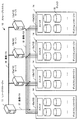
ストレージシステム1は、管理装置2と、情報処理装置3と、複数のストレージユニット4を備える。図1に示すストレージシステム1は、4つのストレージユニット4(4a,4b,4c,4d)を備えるが、3または5以上のストレージユニット4を備えるものであってもよい。
The
ストレージユニット4は、複数のストレージデバイス5を有する。ストレージユニット4は、たとえば、ディスクボックスやディスクエンクロージャなどであり、複数のストレージデバイス5を収容する。ストレージユニット4は、収容する複数のストレージデバイス5の電源供給や冷却、所要のコントロールなどを担う。ストレージデバイス5は、データを格納可能なデバイスであり、たとえば、HDD(Hard Disk Drive)やSSD(Solid State Drive:フラッシュメモリドライブ)などである。
The
管理装置2は、ストレージシステム1におけるストレージ資源を管理し、情報処理装置3へのストレージデバイス5の割当を担う。管理装置2は、通信パス7を介してストレージユニット4と接続し、ストレージユニット4、およびストレージユニット4が収容するストレージデバイス5を管理する。また、管理装置2は、通信パス6を介して情報処理装置3と接続し、情報処理装置3とストレージデバイス5との接続を管理する。
The
情報処理装置3は、管理装置2からストレージ資源の割当を受けて、割当を受けたストレージ資源にデータを格納する。情報処理装置3は、通信パス8を介してストレージユニット4と接続し、割当を受けたストレージ資源、すなわち割当を受けたストレージデバイス5と接続する。
The
情報処理装置3は、構成部3aと、検出部3bと、再構成部3cと、複製部3dを備える。構成部3aは、それぞれ異なるストレージユニット4に属するストレージデバイス5の割当を受けてグループを構成する。グループは、たとえばRAIDグループであり、RAIDの1つにRAID5などがある。図1に示すRAIDグループの構成例では、ストレージデバイス5a,5b,5c,5dは、それぞれデータ「A」,「B」,「C」,「D」を格納してRAIDグループを構成する。ストレージデバイス5a,5b,5c,5dは、それぞれ、異なるストレージユニット4a,4b,4c,4dに属する。
The
このように、グループを構成するストレージデバイス5をそれぞれ異なるストレージユニット4から割り当てることで、ストレージシステム1は、グループを構成する複数のストレージデバイス5の同時故障によるデータロストの危険を低減する。
Thus, by assigning the
検出部3bは、グループを構成するストレージデバイス5の障害を検出する。検出部3bは、通信パス8を介して接続するストレージデバイス5の障害を検出することができる。また、検出部3bは、通信パス6を介して接続する管理装置2からの通知によりストレージデバイス5の障害を検出することができる。また、検出部3bは、管理装置2からの通知によりストレージデバイス5が属するストレージユニット4の障害を検出することができる。
The
再構成部3cは、検出部3bによるグループを構成するストレージデバイス5の障害検出により、障害を検出したストレージデバイス5をグループの構成から外す。再構成部3cは、あらたにストレージデバイス5の割当を受けてグループの再構成をおこなう。このとき、再構成部3cは、構成部3aがグループを構成したように、障害を検出していないストレージデバイス5とは異なるストレージユニット4からストレージデバイス5の割当を受けることが望ましい。しかしながら、再構成部3cは、ストレージ資源の状況によっては、障害を検出していないストレージデバイス5が属するストレージユニット4から割当を受けざるを得ない場合がある。このような場合に、再構成部3cは、障害を検出していないストレージデバイス5が属するストレージユニット4のうちの1つからストレージデバイス5の割当を受けてグループの再構成をおこなう。
The
図1に示すグループの構成例において、再構成部3cは、ストレージデバイス5aの障害検出を受けて、ストレージデバイス5bの属するストレージユニット4bからストレージデバイス5eを割り当てる。したがって、再構成部3cは、ストレージデバイス5aの障害検出後、ストレージデバイス5e,5b,5c,5dに、それぞれデータ「A1(A)」,「B」,「C」,「D」を格納してグループを再構成する。ストレージデバイス5e,5bは、ともにストレージユニット4bに属し、ストレージデバイス5c,5dは、それぞれ、ストレージユニット4c,4dに属する。このとき、ストレージユニット4bに障害が発生すると、ストレージデバイス5e,5bにも障害が発生してデータをロストするおそれがある。
In the group configuration example shown in FIG. 1, the
複製部3dは、障害を検出していないストレージデバイス5が属するストレージユニット4のうち再構成部3cが割当を受けたストレージデバイス5が属するストレージユニット4と異なるストレージユニット4からストレージデバイス5の割当を受ける。複製部3dは、複製部3dが割当を受けたストレージデバイス5に、再構成部3cが割当を受けたストレージデバイス5を複製する。
The duplicating
図1に示すグループの構成例において、複製部3dは、ストレージデバイス5e,5bがともにストレージユニット4bに属することから、ストレージユニット4b以外のストレージユニット4からストレージデバイス5を割り当てる。この場合、複製部3dは、ストレージデバイス5cの属するストレージユニット4cからストレージデバイス5fを割り当てる。複製部3dは、ストレージデバイス5eをストレージデバイス5fに複製する。したがって、複製部3dは、ストレージデバイス5e,5fは、それぞれデータ「A1(A)」,「A2(A)」を格納してRAID1を構成する。
In the group configuration example shown in FIG. 1, the
これにより、ストレージシステム1は、ストレージユニット4b,4c,4dのいずれに障害が発生しても、データをロストすることがない。また、ストレージシステム1は、RAID1による2重化機会を限定するため、グループ構成時に使用するストレージデバイス5の数を抑制できる。したがって、ストレージシステム1は、低コストにして耐障害性に優れるシステムを構築可能である。
As a result, the
[第2の実施形態]
次に、第2の実施形態のストレージシステムの構成について図2を用いて説明する。図2は、第2の実施形態のストレージシステムの構成の一例を示す図である。
[Second Embodiment]
Next, the configuration of the storage system of the second embodiment will be described with reference to FIG. FIG. 2 is a diagram illustrating an example of the configuration of the storage system according to the second embodiment.
ストレージシステム10は、リソースマネージャ11と、サーバ12と、複数のディスクエンクロージャ13を備える。ディスクエンクロージャ13は、ストレージ資源として複数のディスク15を収容する。なお、図2に示すディスクエンクロージャ13は、6つのディスク15を備えるが、2以上を備えるもの(たとえば、24)であればいくつであってもよい。ディスク15は、データを格納可能なストレージデバイスであり、たとえば、HDDやSSDなどである。
The storage system 10 includes a resource manager 11, a
ディスクエンクロージャ13は、スイッチ14を備え、スイッチ14により外部機器(サーバ12)とディスク15との接続および切り離しをおこなう。スイッチ14は、リソースマネージャ11の制御対象であり、通信パス17によりリソースマネージャ11と接続する。
The
ストレージシステム10は、ディスクエンクロージャ13を一単位にしてストレージ資源の交換あるいは増減をおこなうことができる。なお、図2に示すストレージシステム10は、4つのディスクエンクロージャ13(13a,13b,13c,13d)を備えるが、3または5以上のディスクエンクロージャ13を備えるものであってもよい。
The storage system 10 can exchange or increase / decrease storage resources with the
リソースマネージャ11は、ストレージシステム10におけるストレージ資源を管理する管理装置であり、サーバ12へのディスク15の割当を担う。リソースマネージャ11は、通信パス17を介してディスクエンクロージャ13と接続し、ディスクエンクロージャ13、およびディスクエンクロージャ13が収容するディスク15を管理する。また、リソースマネージャ11は、通信パス16を介してサーバ12と接続し、サーバ12とディスク15との接続を管理する。
The resource manager 11 is a management device that manages storage resources in the storage system 10 and is responsible for allocating
リソースマネージャ11は、スイッチ14を制御し、サーバ12とディスク15との接続によりサーバ12へのディスク15の割当をおこなう。また、リソースマネージャ11は、スイッチ14を制御し、サーバ12とディスク15との接続解除(切り離し)によりサーバ12へのディスク15の割当解消をおこなう。なお、図2に示すストレージシステム10は、1つのリソースマネージャ11を備えるが、2以上のリソースマネージャ11を備えて冗長性確保あるいは負荷分散を図るものであってもよい。
The resource manager 11 controls the
サーバ12は、ストレージシステム10においてリソースマネージャ11からストレージ資源の割当を受ける情報処理装置である。サーバ12は、各ディスクエンクロージャ13が備えるスイッチ14と通信パス18を介して接続する。サーバ12は、スイッチ14を介して接続するディスク15の接続と接続解除を、ホットプラグ機能により認識できる。なお、図2に示すストレージシステム10は、3つのサーバ12(12a,12b,12c)を備えるが、任意の数のサーバ12を備えることができる。
The
サーバ12は、複数のディスクエンクロージャ13からそれぞれディスク15の割当を受けて、RAID(たとえば、RAID5)グループを構成する。サーバ12は、複数のRAIDグループを構成可能であり、それぞれのRAIDグループは識別情報によって区別される。このように、RAIDグループを構成するディスク15をそれぞれ異なるディスクエンクロージャ13から割り当てることで、ストレージシステム10は、RAIDグループを構成する複数のディスク15の同時故障によるデータロストの危険を低減する。
The
なお、複数のサーバ12と、複数のディスクエンクロージャ13を、通信パス18を介してそれぞれ接続するようにしたが、別途スイッチを設けて接続するようにしてもよい。
次に、第2の実施形態のディスクエンクロージャの構成について図3を用いて説明する。図3は、第2の実施形態のディスクエンクロージャの構成の一例を示す図である。
Although the plurality of
Next, the configuration of the disk enclosure of the second embodiment will be described with reference to FIG. FIG. 3 is a diagram illustrating an example of the configuration of the disk enclosure according to the second embodiment.
ディスクエンクロージャ13は、スイッチ14と、複数のディスク15と、コントローラ25と、電源部26と、冷却部27を備える。スイッチ14は、各ディスク15について外部機器との接続および切り離しをおこなう。冷却部27は、ディスク15、電源部26を含めてディスクエンクロージャ13の筺体内を冷却する。電源部26は、コントローラ25、冷却部27、スイッチ14、およびディスク15を含むディスクエンクロージャ13内の各機器に電力を供給する。
The
コントローラ25は、ディスクエンクロージャ13内の各機器を制御する。また、コントローラ25は、ディスクエンクロージャ13内の各機器の状態監視をおこない、ディスクエンクロージャ13内の各機器の故障、またはディスクエンクロージャ13全体としての故障を検出する。コントローラ25は、検出した故障をリソースマネージャ11に通知する。
The
次に、第2の実施形態のサーバのハードウェア構成について図4を用いて説明する。図4は、第2の実施形態のサーバのハードウェア構成の一例を示す図である。
サーバ12は、プロセッサ101によって装置全体が制御されている。プロセッサ101には、バス106を介してRAM(Random Access Memory)102と複数の周辺機器が接続されている。プロセッサ101は、マルチプロセッサであってもよい。プロセッサ101は、たとえばCPU(Central Processing Unit)、MPU(Micro Processing Unit)、DSP(Digital Signal Processor)、ASIC(Application Specific Integrated Circuit)、またはPLD(Programmable Logic Device)である。またプロセッサ101は、CPU、MPU、DSP、ASIC、PLDのうちの2以上の要素の組み合わせであってもよい。
Next, the hardware configuration of the server according to the second embodiment will be described with reference to FIG. FIG. 4 is a diagram illustrating an example of a hardware configuration of the server according to the second embodiment.
The
RAM102は、サーバ12の主記憶装置として使用される。RAM102には、プロセッサ101に実行させるオペレーティングシステム(Operating System)のプログラムやファームウェア、アプリケーションプログラムの少なくとも一部が一時的に格納される。また、RAM102には、プロセッサ101による処理に必要な各種データ(たとえば、システム制御の情報管理)が格納される。また、RAM102は、各種データの格納に用いるメモリと別体にキャッシュメモリを含むものであってもよい。
The RAM 102 is used as a main storage device of the
バス106に接続されている周辺機器としては、不揮発性メモリ103、入出力インタフェース104、および通信インタフェース105がある。
不揮発性メモリ103は、サーバ12の電源遮断時においても記憶内容を保持する。不揮発性メモリ103は、たとえば、EEPROM(Electrically Erasable Programmable Read-Only Memory)やフラッシュメモリなどの半導体記憶装置や、HDDなどである。また、不揮発性メモリ103は、サーバ12の補助記憶装置として使用される。不揮発性メモリ103には、オペレーティングシステムのプログラムやファームウェア、アプリケーションプログラム、および各種データが格納される。
Peripheral devices connected to the bus 106 include a nonvolatile memory 103, an input / output interface 104, and a communication interface 105.
The non-volatile memory 103 retains the stored contents even when the
入出力インタフェース104は、図示しない入出力装置と接続して入出力をおこなう。
通信インタフェース105は、通信パス16,18を形成するネットワークと接続することで、通信パス16,18を介して、リソースマネージャ11やディスクエンクロージャ13との間でデータの送受信をおこなう。
The input / output interface 104 is connected to an input / output device (not shown) to perform input / output.
The communication interface 105 transmits and receives data to and from the resource manager 11 and the
以上のようなハードウェア構成によって、第2の実施形態のサーバ12の処理機能を実現することができる。なお、サーバ12の他、リソースマネージャ11、コントローラ25、第1の実施形態に示した管理装置2、情報処理装置3、ストレージユニット4も、図4に示したサーバ12と同様のハードウェアにより実現することができる。
With the hardware configuration as described above, the processing function of the
サーバ12は、たとえばコンピュータ読み取り可能な記録媒体に記録されたプログラムを実行することにより、第2の実施形態の処理機能を実現する。サーバ12に実行させる処理内容を記述したプログラムは、様々な記録媒体に記録しておくことができる。たとえば、サーバ12に実行させるプログラムを不揮発性メモリ103に格納しておくことができる。プロセッサ101は、不揮発性メモリ103内のプログラムの少なくとも一部をRAM102にロードし、プログラムを実行する。またサーバ12に実行させるプログラムを、図示しない光ディスク、メモリ装置、メモリカードなどの可搬型記録媒体に記録しておくこともできる。光ディスクには、DVD(Digital Versatile Disc)、DVD−RAM、CD−ROM(Compact Disc Read Only Memory)、CD−R(Recordable)/RW(ReWritable)などがある。メモリ装置は、入出力インタフェース104あるいは図示しない機器接続インタフェースとの通信機能を搭載した記録媒体である。たとえば、メモリ装置は、メモリリーダライタによりメモリカードへのデータの書き込み、またはメモリカードからのデータの読み出しをおこなうことができる。メモリカードは、カード型の記録媒体である。
The
可搬型記録媒体に格納されたプログラムは、たとえばプロセッサ101からの制御により、不揮発性メモリ103にインストールされた後、実行可能となる。またプロセッサ101が、可搬型記録媒体から直接プログラムを読み出して実行することもできる。 The program stored in the portable recording medium becomes executable after being installed in the nonvolatile memory 103 under the control of the processor 101, for example. The processor 101 can also read and execute a program directly from a portable recording medium.
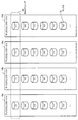
次に、第2の実施形態のサーバが構成するRAIDグループについて図5を用いて説明する。図5は、第2の実施形態のサーバが構成するRAIDグループの一例を示す図である。 Next, a RAID group configured by the server according to the second embodiment will be described with reference to FIG. FIG. 5 is a diagram illustrating an example of a RAID group configured by the server according to the second embodiment.
ディスクエンクロージャ13aは、複数のディスク15(「#A1」,「#A2」,「#A3」,・・・)を備える。ディスクエンクロージャ13bは、複数のディスク15(「#B1」,「#B2」,「#B3」,・・・)を備える。ディスクエンクロージャ13cは、複数のディスク15(「#C1」,「#C2」,「#C3」,・・・)を備える。ディスクエンクロージャ13dは、複数のディスク15(「#D1」,「#D2」,「#D3」,・・・)を備える。
The
サーバ12(たとえば、サーバ12a)は、ディスクエンクロージャ13a,13b,13c,13dからそれぞれディスク15(「#A1」,「#B1」,「#C1」,「#D1」)の割当を受けてRAIDグループ30(たとえば、RAID5)を構成する。
The server 12 (for example, the
RAIDグループ30は、ディスク15(「#A1」,「#B1」,「#C1」,「#D1」)がそれぞれ異なるディスクエンクロージャ13に属する。そのため、サーバ12は、4つのディスクエンクロージャ13のうちの1つが故障しても、故障するディスク15が1つに限られる。したがって、サーバ12は、RAIDグループ30のデータへのアクセスを継続可能であり、またRAIDグループ30を再構成可能である。
In the
次に、第2の実施形態のサーバが管理するRAID構成情報について図6を用いて説明する。図6は、第2の実施形態のRAID構成情報の一例を示す図である。
RAID構成情報50は、サーバ12(たとえば、サーバ12a)が管理するRAIDグループの構成を示す情報である。サーバ12は、たとえば、不揮発性メモリ103にRAID構成情報50を保持する。RAID構成情報50は、RAIDグループID(Identification)、ブロックNo.、ステータス、ディスクエンクロージャID、ディスクIDを含む。
Next, RAID configuration information managed by the server of the second embodiment will be described with reference to FIG. FIG. 6 is a diagram illustrating an example of RAID configuration information according to the second embodiment.
The
RAIDグループIDは、サーバ12が管理するRAIDグループ30を識別するための情報である。RAID構成情報50に示すRAIDグループIDは、いずれも「#0001」であり、RAID構成情報50に示す情報は、同一のRAIDグループに属する情報である。
The RAID group ID is information for identifying the
ブロックNo.は、RAIDグループ30を構成するディスク15に付したシリアル番号である。ステータスは、RAIDグループ30を構成するディスク15の状態を示す。通常時のステータスは、「物理」である。ディスクエンクロージャIDは、ストレージシステム10内でディスクエンクロージャ13を一意に識別可能な識別情報である。ディスクIDは、各ディスクエンクロージャ13内でディスク15を一意に識別可能な識別情報である。したがって、サーバ12は、ディスクエンクロージャIDとディスクIDとから、ストレージシステム10内でディスク15を一意に識別できる。
Block No. Is a serial number assigned to the
したがって、RAID構成情報50は、ブロックNo.「1」,「2」,「3」,「4」の4つのディスク15からRAIDグループID「#0001」のRAIDグループ30が構成されていることを示す。また、RAID構成情報50は、ステータス「物理」より、通常のRAIDグループが構成されていることを示す。また、RAID構成情報50は、ブロックNo.「1」のディスク15がディスクエンクロージャID「#A」、ディスクID「#1」であることを示す。同様に、RAID構成情報50は、ブロックNo.「2」のディスク15がディスクエンクロージャID「#B」、ディスクID「#1」であることを示す。同様に、RAID構成情報50は、ブロックNo.「3」のディスク15がディスクエンクロージャID「#C」、ディスクID「#1」であることを示す。同様に、RAID構成情報50は、ブロックNo.「4」のディスク15がディスクエンクロージャID「#D」、ディスクID「#1」であることを示す。
Therefore, the
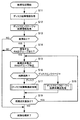
次に、第2の実施形態の故障処理について図7を用いて説明する。図7は、第2の実施形態の故障処理のフローチャートを示す図である。
故障処理は、ストレージ資源の故障を検出してRAIDの再構成をおこなう処理である。故障処理は、サーバ12が定期的に実行する処理である。
Next, failure processing according to the second embodiment will be described with reference to FIG. FIG. 7 is a diagram illustrating a flowchart of failure processing according to the second embodiment.
The failure process is a process of reconfiguring RAID by detecting a failure of storage resources. The failure process is a process that the
[ステップS11]サーバ12のプロセッサ101(制御部)は、ディスク故障情報を取得する。ディスク故障情報は、サーバ12に割当のあるディスク15の故障に関する情報である。プロセッサ101は、通信パス18を介して定期または不定期にディスク15の稼働状態を監視することによりディスク15の故障を検出してディスク故障情報を生成する。プロセッサ101は、ディスク15へのポーリングまたはディスク15からの通知により、ディスク15の稼働状態を監視することができる。
[Step S11] The processor 101 (control unit) of the
[ステップS12]制御部は、ディスクエンクロージャ故障情報を取得する。ディスクエンクロージャ故障情報は、リソースマネージャ11が管理するディスクエンクロージャ13の故障に関する情報である。リソースマネージャ11は、通信パス17を介して定期または不定期にディスクエンクロージャ13の稼働状態を監視することによりディスクエンクロージャ13の故障を検出してディスクエンクロージャ故障情報を生成する。リソースマネージャ11は、ディスクエンクロージャ13へのポーリングまたはディスクエンクロージャ13からの通知により、ディスクエンクロージャ13の稼働状態を監視することができる。なお、リソースマネージャ11は、ディスクエンクロージャ13を介して検出したディスク故障にもとづいてディスク故障情報を生成してサーバ12に通知するようにしてもよい。
[Step S12] The control unit acquires disk enclosure failure information. The disk enclosure failure information is information related to a failure of the
[ステップS13]制御部は、ディスク故障情報およびディスクエンクロージャ故障情報からディスク15の故障の有無を判定する。制御部は、ディスク15の故障ありと判定した場合にステップS14にすすみ、ディスク15の故障なしと判定した場合に故障処理を終了する。
[Step S13] The control unit determines whether there is a failure of the
[ステップS14]制御部は、RAID構成情報を参照して故障したディスク15に関係するRAIDグループの有無を判定する。制御部は、故障したディスク15に関係するRAIDグループがある場合にステップS15にすすみ、故障したディスク15に関係するRAIDグループがない場合に故障処理を終了する。
[Step S14] The control unit determines whether or not there is a RAID group related to the failed
[ステップS15]制御部は、故障したディスク15を構成要素とするRAIDグループの1つを特定する。
[ステップS16]制御部は、故障個所がディスク15かディスクエンクロージャ13かを判定する。制御部は、故障個所がディスク15の場合にステップS17にすすみ、故障個所がディスクエンクロージャ13の場合にステップS18にすすむ。
[Step S15] The control unit identifies one of the RAID groups having the failed
[Step S16] The control unit determines whether the failure location is the
[ステップS17]制御部は、ディスク故障再構成処理を実行する。ディスク故障再構成処理は、ディスク15が故障した場合にRAIDの再構成をおこなう処理である。詳細は、図8を用いて後で説明する。
[Step S17] The control unit executes a disk failure reconfiguration process. The disk failure reconfiguration process is a process for performing RAID reconfiguration when the
[ステップS18]制御部は、ディスクエンクロージャ故障再構成処理を実行する。ディスクエンクロージャ故障再構成処理は、ディスクエンクロージャ13が故障した場合にRAIDの再構成をおこなう処理である。詳細は、図9を用いて後で説明する。
[Step S18] The control unit executes a disk enclosure failure reconfiguration process. The disk enclosure failure reconfiguration process is a process for performing RAID reconfiguration when the
[ステップS19]制御部は、ステップS15で特定したRAIDグループの他に、故障したディスク15を構成要素とするRAIDグループ、すなわち再構成対象のRAIDグループがまだあるか否かを判定する。制御部は、再構成対象のRAIDグループがあると判定した場合にステップS15にすすみ、再構成対象のRAIDグループがないと判定した場合に故障処理を終了する。
[Step S19] In addition to the RAID group specified in Step S15, the control unit determines whether there is still a RAID group including the failed
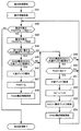
次に、第2の実施形態のディスク故障再構成処理について図8を用いて説明する。図8は、第2の実施形態のディスク故障再構成処理のフローチャートを示す図である。ディスク故障再構成処理は、故障処理のステップS17でサーバ12が実行する処理である。
Next, disk failure reconfiguration processing according to the second embodiment will be described with reference to FIG. FIG. 8 is a diagram illustrating a flowchart of disk failure reconfiguration processing according to the second embodiment. The disk failure reconstruction process is a process executed by the
[ステップS21]サーバ12のプロセッサ101(制御部)は、故障したディスク15が属するディスクエンクロージャ13(DE:Disk Enclosure)、すなわち故障ディスクのDEに空きディスクがあるか否かを判定する。制御部は、リソースマネージャ11に照会することにより、故障ディスクのDEに空きディスクがあるか否かを判定することができる。制御部は、故障ディスクのDEに空きディスクがある場合にステップS22にすすみ、故障ディスクのDEに空きディスクがない場合にステップS23にすすむ。
[Step S21] The processor 101 (control unit) of the
[ステップS22]制御部は、故障ディスクが属するディスクエンクロージャ13からディスク15の割当を受けて、代替ディスクを獲得する。
[ステップS23]制御部は、RAIDグループを構成するディスクが属さないディスクエンクロージャ13(DE)、すなわちRAID構成外DEに空きディスクがあるか否かを判定する。制御部は、リソースマネージャ11に照会することにより、RAID構成外DEに空きディスクがあるか否かを判定することができる。制御部は、空きディスクがある場合にステップS24にすすみ、空きディスクがない場合にステップS25にすすむ。
[Step S22] The control unit receives an allocation of the
[Step S23] The control unit determines whether or not there is a free disk in the disk enclosure 13 (DE) to which the disk constituting the RAID group does not belong, that is, the RAID non-RAID configured DE. The control unit can determine whether or not there is a free disk in the RAID unconfigured DE by making an inquiry to the resource manager 11. The control unit proceeds to step S24 when there is a free disk, and proceeds to step S25 when there is no free disk.
[ステップS24]制御部は、RAID構成外DEから代替ディスクを獲得する。
[ステップS25]制御部は、RAIDグループを構成するディスクが属する2以上のディスクエンクロージャ13(DE)、すなわちRAID構成DEに空きディスクがあるか否かを判定する。制御部は、リソースマネージャ11に照会することにより、2以上のRAID構成DEに空きディスクがあるか否かを判定することができる。制御部は、2以上のRAID構成DEに空きディスクがない場合にステップS26にすすみ、2以上のRAID構成DEに空きディスクがある場合にステップS27にすすむ。
[Step S24] The control unit obtains an alternative disk from the RAID unconfigured DE.
[Step S25] The control unit determines whether or not there is a free disk in the two or more disk enclosures 13 (DE) to which the disks constituting the RAID group belong, that is, the RAID configuration DE. The control unit can determine whether or not there are free disks in two or more RAID configurations DE by making an inquiry to the resource manager 11. The control unit proceeds to step S26 when there is no free disk in two or more RAID configuration DEs, and proceeds to step S27 when there is a free disk in two or more RAID configuration DEs.
[ステップS26]制御部は、1つのRAID構成DEからディスク15の割当を受けて、代替ディスクを獲得する。
[ステップS27]制御部は、2以上のRAID構成DEのうちの2つのRAID構成DEから1つずつディスク15の割当を受けて、代替ディスクを獲得する。
[Step S26] The control unit receives an allocation of the
[Step S27] The control unit receives the allocation of the
[ステップS28]制御部は、獲得した代替ディスクを含めてRAID再構成(第1のリビルド処理)をおこなう。このとき、ステップS22,S24において獲得した代替ディスクによりRAID再構成したRAIDグループは、RAIDグループを構成するディスクがそれぞれ異なるディスクエンクロージャ13に属する。一方、ステップS26において獲得した代替ディスクによりRAID再構成したRAIDグループは、RAIDグループを構成するディスクが一部のディスクエンクロージャ13に重複して属する。そのため、このRAIDグループは、一部のディスクエンクロージャ13が故障した場合に、データロストのおそれがある。
[Step S28] The control unit performs RAID reconstruction (first rebuild process) including the acquired replacement disk. At this time, the RAID groups reconfigured by RAID using the replacement disks acquired in steps S22 and S24 belong to
[ステップS29]制御部は、獲得した代替ディスクを含めてRAID1併用RAID再構成(第2のリビルド処理)をおこなう。ステップS27において獲得した代替ディスクによりRAID再構成したRAIDグループは、RAIDグループを構成するディスクが一部のディスクエンクロージャ13に重複して属する。制御部は、2つの代替ディスクがそれぞれの複製となるようにして、RAIDグループを再構成する。RAIDグループの再構成については、後で図10から図12を用いてRAIDグループの再構成例を挙げて説明する。
[Step S29] The control unit performs RAID1 combined RAID reconstruction (second rebuild process) including the acquired replacement disk. In the RAID group reconfigured by the replacement disk acquired in step S27, the disks constituting the RAID group belong to some of the
[ステップS30]制御部は、RAID構成情報を更新してディスク故障再構成処理を終了する。
次に、第2の実施形態のディスクエンクロージャ故障再構成処理について図9を用いて説明する。図9は、第2の実施形態のディスクエンクロージャ故障再構成処理のフローチャートを示す図である。ディスクエンクロージャ故障再構成処理は、故障処理のステップS18でサーバ12が実行する処理である。
[Step S30] The control unit updates the RAID configuration information and ends the disk failure reconfiguration process.
Next, disk enclosure failure reconfiguration processing according to the second embodiment will be described with reference to FIG. FIG. 9 is a flowchart of the disk enclosure failure reconfiguration process according to the second embodiment. The disk enclosure failure reconfiguration process is a process executed by the
[ステップS31]サーバ12のプロセッサ101(制御部)は、RAIDグループを構成するディスクが属さないディスクエンクロージャ13(DE)、すなわちRAID構成外DEに空きディスクがあるか否かを判定する。制御部は、リソースマネージャ11に照会することにより、RAID構成外DEに空きディスクがあるか否かを判定することができる。制御部は、空きディスクがある場合にステップS32にすすみ、空きディスクがない場合にステップS33にすすむ。
[Step S31] The processor 101 (control unit) of the
[ステップS32]制御部は、RAID構成外DEから代替ディスクを獲得する。
[ステップS33]制御部は、RAIDグループを構成するディスクが属する2以上のディスクエンクロージャ13(DE)、すなわちRAID構成DEに空きディスクがあるか否かを判定する。制御部は、リソースマネージャ11に照会することにより、2以上のRAID構成DEに空きディスクがあるか否かを判定することができる。制御部は、2以上のRAID構成DEに空きディスクがない場合にステップS34にすすみ、2以上のRAID構成DEに空きディスクがある場合にステップS35にすすむ。
[Step S32] The control unit obtains an alternative disk from the RAID unconfigured DE.
[Step S33] The control unit determines whether or not there is a free disk in two or more disk enclosures 13 (DE) to which the disks constituting the RAID group belong, that is, the RAID configuration DE. The control unit can determine whether or not there are free disks in two or more RAID configurations DE by making an inquiry to the resource manager 11. The control unit proceeds to step S34 when there is no free disk in two or more RAID configuration DEs, and proceeds to step S35 when there is a free disk in two or more RAID configuration DEs.
[ステップS34]制御部は、1つのRAID構成DEからディスク15の割当を受けて、代替ディスクを獲得する。
[ステップS35]制御部は、2以上のRAID構成DEのうちの2つのRAID構成DEから1つずつディスク15の割当を受けて、代替ディスクを獲得する。
[Step S34] The control unit receives the allocation of the
[Step S35] The control unit receives the allocation of the
[ステップS36]制御部は、獲得した代替ディスクを含めてRAID再構成(第1のリビルド処理)をおこなう。このとき、ステップS32において獲得した代替ディスクによりRAID再構成したRAIDグループは、RAIDグループを構成するディスクがそれぞれ異なるディスクエンクロージャ13に属する。一方、ステップS34において獲得した代替ディスクによりRAID再構成したRAIDグループは、RAIDグループを構成するディスクが一部のディスクエンクロージャ13に重複して属する。そのため、このRAIDグループは、一部のディスクエンクロージャ13が故障した場合に、データロストのおそれがある。
[Step S36] The control unit performs RAID reconfiguration (first rebuild process) including the acquired replacement disk. At this time, the RAID groups reconfigured by RAID using the replacement disk acquired in step S32 belong to
[ステップS37]制御部は、獲得した代替ディスクを含めてRAID1併用RAID再構成(第2のリビルド処理)をおこなう。ステップS35において獲得した代替ディスクによりRAID再構成したRAIDグループは、RAIDグループを構成するディスクが一部のディスクエンクロージャ13に重複して属する。制御部は、2つの代替ディスクがそれぞれの複製となるようにして、RAIDグループを再構成する。RAIDグループの再構成については、後で図10から図12を用いてRAIDグループの再構成例を挙げて説明する。
[Step S37] The control unit performs RAID1 combined RAID reconstruction (second rebuilding process) including the acquired replacement disk. In the RAID group reconfigured by RAID using the replacement disk acquired in step S35, the disks constituting the RAID group belong to some of the
[ステップS38]制御部は、RAID構成情報を更新してディスクエンクロージャ故障再構成処理を終了する。
次に、第2の実施形態のRAID構成DEから代替ディスクを獲得する場合のRAID再構成について図10から図12を用いて説明する。まず、RAID構成DEの1つが故障して、代替ディスクを他のRAID構成DEから獲得しなければならない場合について図10を用いて説明する。図10は、第2の実施形態のサーバが構成するRAIDグループの一例を示す図である。
[Step S38] The control unit updates the RAID configuration information and ends the disk enclosure failure reconfiguration process.
Next, RAID reconfiguration when an alternative disk is acquired from the RAID configuration DE according to the second embodiment will be described with reference to FIGS. First, a case where one of the RAID configuration DEs fails and an alternative disk must be acquired from another RAID configuration DE will be described with reference to FIG. FIG. 10 is a diagram illustrating an example of a RAID group configured by the server according to the second embodiment.
ディスクエンクロージャ13aは、故障により、複数のディスク15(「#A1」,「#A2」,「#A3」,・・・)が故障した状態である。制御部は、ディスクエンクロージャ13aの故障検出により、他のディスクエンクロージャ13からディスク15「#A1」を代替するディスク15の割当を受ける。たとえば、ディスク故障再構成処理のステップS26、またはディスクエンクロージャ故障再構成処理のステップS34の場合、制御部は、ディスクエンクロージャ13bからディスク15「#B2」の割当を受ける。また、ディスク故障再構成処理のステップS27、またはディスクエンクロージャ故障再構成処理のステップS35の場合、制御部は、ディスク15「#B2」に加えて、ディスクエンクロージャ13cからディスク15「#C2」の割当を受ける。
The
制御部は、ディスクエンクロージャ13aのディスク15「#A1」に代えてディスクエンクロージャ13bのディスク15「#B2」を加えて、RAIDグループ30をRAIDグループ30aとして再構成する。
The control unit adds the
すなわち、制御部は、ディスクエンクロージャ13b,13c,13dからそれぞれディスク15(「#B2」,「#B1」,「#C1」,「#D1」)の割当を受けてRAIDグループ30をRAIDグループ30aとして再構成する。
That is, the control unit receives the allocation of the disks 15 (“# B2”, “# B1”, “# C1”, “# D1”) from the
RAIDグループ30aは、ディスク15(「#B2」,「#B1」)が同一のディスクエンクロージャ13bに属する。そのため、サーバ12は、ディスクエンクロージャ13bが故障するとデータロストするおそれのある状態である。したがって、ディスク故障再構成処理のステップS26、またはディスクエンクロージャ故障再構成処理のステップS34を経てRAID再構成をおこなった場合、サーバ12は、ディスクエンクロージャ13bが故障した場合にデータロストするおそれがある。
In the
一方、サーバ12は、2つのRAID構成DEからそれぞれ代替ディスクを獲得できた場合は、データロストのおそれのないRAID再構成をおこなうことができる。2つのRAID構成DEからそれぞれ代替ディスクを獲得できた場合について図11を用いて説明する。図11は、第2の実施形態のサーバが構成するRAIDグループの一例を示す図である。
On the other hand, when the
制御部は、ディスク15「#B2」に加えて、ディスクエンクロージャ13cからディスク15「#C2」の割当を受けた場合、ディスク15「#B2」をディスク15「#C2」に複製する。すなわち、制御部は、ディスク15「#B2」とディスク15「#C2」とでRAID1を構成する。言い換えれば、制御部は、ディスクエンクロージャ13aのディスク15「#A1」を、ディスク15「#B2」とディスク15「#C2」とに置き換える。
When receiving the allocation of the
これにより、制御部は、ディスクエンクロージャ13b,13c,13dからそれぞれディスク15(「#B2」,「#C2」,「#B1」,「#C1」,「#D1」)の割当を受けて、RAID1を併用してRAIDグループ30をRAIDグループ30bとして再構成する。
Thus, the control unit receives the allocation of the disks 15 (“# B2”, “# C2”, “# B1”, “# C1”, “# D1”) from the
RAIDグループ30bは、ディスク15(「#B2」,「#B1」)が同一のディスクエンクロージャ13bに属し、ディスク15(「#C2」,「#C1」)が同一のディスクエンクロージャ13bに属する。しかしながら、ディスクエンクロージャ13b,13cのいずれか一方が故障しても、サーバ12は、RAIDグループ30に対してアクセス可能である。
In the
したがって、ストレージシステム10は、ディスクエンクロージャ13(ストレージユニット単位)の障害によるデータロストを防止できる。また、ストレージシステム10は、通常時において、各ディスク15を2重化することを要しないから信頼性の向上とストレージ資源の効率的な利用とを両立することができる。
Therefore, the storage system 10 can prevent data loss due to a failure of the disk enclosure 13 (unit of storage unit). In addition, since the storage system 10 does not require duplication of each
RAID1併用なしのRAID再構成をおこなった場合、ディスク15が2台存在しているディスクエンクロージャ13の故障でデータロストのおそれがある。このとき、ディスク故障率をfhdd、ディスクエンクロージャ故障率をfdeとすると、故障率は、fhdd×(fhdd+fde)となる。
When RAID reconstruction without
一方、RAID1併用RAID再構成をおこなった場合、ディスク15が2台存在しているディスクエンクロージャ13の故障があってもデータロストのおそれがない。このとき、故障率は、fhdd×fhddとなり、RAID1併用なしのRAID再構成をおこなった場合と比較して故障率を低減できる。
On the other hand, when RAID reconstruction with
次に、第2の実施形態のRAID1併用RAID再構成後のRAID構成情報について図12を用いて説明する。図12は、第2の実施形態のRAID構成情報の一例を示す図である。
Next, RAID configuration information after
RAID構成情報51は、RAID構成情報50をRAID1併用RAID再構成後に更新した情報である。
RAID構成情報51は、ブロックNo.「1」が2つと、ブロックNo.「2」,「3」,「4」が1つずつの合計5つのディスク15からRAIDグループID「#0001」のRAIDグループ30が構成されていることを示す。また、RAID構成情報51は、ステータス「RAID1」より、ブロックNo.「1」の2つのディスク15がRAID1を構成していることを示す。ステータス「RAID1」は、ディスク15が複製を有することを示す。すなわち、ステータス「RAID1」は、ディスク15が複製を有するか否かを判別可能な複製判別情報に相当する。
The RAID configuration information 51 is information obtained by updating the
The RAID configuration information 51 includes a block No. “1” is two and block No. This indicates that the
また、RAID構成情報51は、ブロックNo.「1」の1つのディスク15がディスクエンクロージャID「#B」、ディスクID「#2」であることを示す。また、RAID構成情報51は、ブロックNo.「1」のもう1つのディスク15がディスクエンクロージャID「#C」、ディスクID「#2」であることを示す。同様に、RAID構成情報51は、ブロックNo.「2」のディスク15がディスクエンクロージャID「#B」、ディスクID「#1」であることを示す。同様に、RAID構成情報51は、ブロックNo.「3」のディスク15がディスクエンクロージャID「#C」、ディスクID「#1」であることを示す。同様に、RAID構成情報51は、ブロックNo.「4」のディスク15がディスクエンクロージャID「#D」、ディスクID「#1」であることを示す。
The RAID configuration information 51 includes a block No. It indicates that one
次に、第2の実施形態の復旧処理について図13を用いて説明する。図13は、第2の実施形態の復旧処理のフローチャートを示す図である。復旧処理は、故障したディスク15や、故障したディスクエンクロージャ13の交換処理など、ストレージ資源のメンテナンスの終了を契機にしてサーバ12が実行する処理である。たとえば、復旧処理は、管理者による指示にもとづいて実行されるが、定期的に実行されるものであってもよい。
Next, the recovery process of the second embodiment will be described with reference to FIG. FIG. 13 is a diagram illustrating a flowchart of the recovery process according to the second embodiment. The recovery process is a process executed by the
[ステップS41]サーバ12のプロセッサ101(制御部)は、復旧情報を取得する。復旧情報は、サーバ12に割当のあるディスク15、またはサーバ12に割当のあるディスク15が属するディスクエンクロージャ13の故障に関する情報である。プロセッサ101は、通信パス18を介して定期または不定期にディスク15の稼働状態を監視することによりディスク15の復旧を検出してディスク15に関する復旧情報を生成する。リソースマネージャ11は、通信パス17を介して定期または不定期にディスクエンクロージャ13の稼働状態を監視することによりディスクエンクロージャ13の復旧を検出してディスクエンクロージャに関する復旧情報を生成する。なお、リソースマネージャ11は、ディスクエンクロージャ13を介して検出したディスク15の復旧にもとづいてディスクに関する復旧情報を生成してサーバ12に通知するようにしてもよい。なお、ここでいう復旧は、故障したディスク15、または故障したディスクエンクロージャ13の交換であるが、ディスク15の割当可能な状態への移行という観点から、ディスク15またはディスクエンクロージャ13の追加を含むものであってもよい。
[Step S41] The processor 101 (control unit) of the
[ステップS42]制御部は、復旧したディスク15を割当可能なRAIDグループの有無を判定する。制御部は、復旧したディスク15を割当可能なRAIDグループがある場合にステップS43にすすみ、復旧したディスク15を割当可能なRAIDグループがない場合に復旧処理を終了する。
[Step S42] The control unit determines whether there is a RAID group to which the recovered
[ステップS43]制御部は、復旧したディスク15を割当可能なRAIDグループの1つを特定する。
[ステップS44]制御部は、1つのディスクエンクロージャ13(同一DE)に属するRAIDグループを構成するディスク(RAID構成ディスク)の有無を判定する。制御部は、同一DEに属するRAID構成ディスクがある場合にステップS45にすすみ、同一DEに属するRAID構成ディスクがない場合にステップS49にすすむ。
[Step S43] The control unit identifies one of the RAID groups to which the recovered
[Step S44] The control unit determines whether or not there is a disk (RAID configuration disk) that constitutes a RAID group belonging to one disk enclosure 13 (same DE). The control unit proceeds to step S45 when there is a RAID constituent disk belonging to the same DE, and proceeds to step S49 when there is no RAID constituent disk belonging to the same DE.
[ステップS45]制御部は、復旧情報とRAID構成情報とにもとづいて、特定したRAIDグループに属するディスクエンクロージャ13(RAID構成DE)から代替ディスクを獲得可能か否かを判定する。制御部は、RAID構成DEから代替ディスクを獲得できる場合にステップS46にすすみ、RAID構成DEから代替ディスクを獲得できない場合にステップS49にすすむ。 [Step S45] Based on the recovery information and the RAID configuration information, the control unit determines whether or not a replacement disk can be acquired from the disk enclosure 13 (RAID configuration DE) belonging to the specified RAID group. The control unit proceeds to step S46 when an alternative disk can be acquired from the RAID configuration DE, and proceeds to step S49 when an alternative disk cannot be acquired from the RAID configuration DE.
[ステップS46]制御部は、代替ディスクを獲得する。
[ステップS47]制御部は、同一DEに属するRAID構成ディスクについて代替ディスクとの間でRAID1化をおこなう。
[Step S46] The control unit obtains an alternative disk.
[Step S47] The control unit performs
[ステップS48]制御部は、RAID構成情報を更新してステップS49にすすむ。
[ステップS49]制御部は、復旧情報とRAID構成情報とにもとづいて、特定したRAIDグループに属さないディスクエンクロージャ13(RAID構成外DE)から代替ディスクを獲得可能か否かを判定する。制御部は、RAID構成外DEから代替ディスクを獲得できる場合にステップS50にすすみ、RAID構成外DEから代替ディスクを獲得できない場合にステップS42にすすむ。
[Step S48] The control unit updates the RAID configuration information and proceeds to Step S49.
[Step S49] Based on the recovery information and the RAID configuration information, the control unit determines whether or not a replacement disk can be acquired from the disk enclosure 13 (RAID non-RAID configuration) that does not belong to the specified RAID group. The control unit proceeds to step S50 when an alternative disk can be acquired from a non-RAID configuration DE, and proceeds to step S42 when an alternative disk cannot be acquired from a non-RAID configuration DE.
[ステップS50]制御部は、RAID構成情報のステータスを参照して、特定したRAIDグループにRAID1があるか否かを判定する。制御部は、特定したRAIDグループにRAID1がある場合にステップS51にすすみ、特定したRAIDグループにRAID1がない場合にステップS42にすすむ。
[Step S50] The control unit refers to the status of the RAID configuration information and determines whether there is
[ステップS51]制御部は、RAID構成外DEからから代替ディスクを獲得する。
[ステップS52]制御部は、RAID1を構成していたディスク15から代替ディスクにコピーバック処理をおこなう。
[Step S51] The control unit obtains an alternative disk from the RAID unconfigured DE.
[Step S52] The control unit performs a copy-back process from the
[ステップS53]制御部は、RAID1を構成していたディスク15を解放する。
[ステップS54]制御部は、RAID構成情報を更新してステップS42にすすむ。
ここで、獲得ディスクへのコピーバックと、RAID1を構成していたディスク15の解放について図14を用いて説明する。図14は、第2の実施形態のサーバが構成するRAIDグループの一例を示す図である。
[Step S53] The control unit releases the
[Step S54] The control unit updates the RAID configuration information and proceeds to step S42.
Here, copy back to the acquisition disk and release of the
図11に示したRAIDグループ30bは、ディスクエンクロージャ13aが故障し、RAID1を併用してRAIDグループを構成している状態である。ここで、図14に示すようにディスクエンクロージャ13aが復旧した場合、制御部は、ディスクエンクロージャ13aのディスク15(たとえば、ディスク15「#A1」)を獲得する。制御部は、RAID1を構成していたディスク15「#B2」からディスク15「#A1」にコピーバック処理をおこなう。これにより、サーバ12は、RAIDグループ30cを再構成することができる。また、制御部は、RAID1を構成していたディスク15「#B2」,「#C2」を解放対象31として、リソースマネージャ11に解放依頼をおこない、サーバ12への割当から解放する。
The
したがって、ストレージシステム10は、ディスクエンクロージャ13(ストレージユニット単位)の復旧により、RAID1を併用していたRAIDグループを復旧することができる。
Therefore, the storage system 10 can recover the RAID group that has used
[第3の実施形態]
次に、第3の実施形態のディスクエンクロージャ故障再構成処理について図15、図16を用いて説明する。図15および図16は、第3の実施形態のディスクエンクロージャ故障再構成処理のフローチャートを示す図である。第3の実施形態のディスクエンクロージャ故障再構成処理は、RAID1を併用するRAIDグループを構成するディスクエンクロージャ13の故障に対応する。
[Third Embodiment]
Next, a disk enclosure failure reconfiguration process according to the third embodiment will be described with reference to FIGS. 15 and 16 are flowcharts of the disk enclosure failure reconfiguration process according to the third embodiment. The disk enclosure failure reconfiguration processing according to the third embodiment corresponds to a failure of the
[ステップS61]サーバ12のプロセッサ101(制御部)は、故障ディスクのステータスを確認する。制御部は、故障ディスクのステータスが「物理」である場合にステップS66にすすみ、故障ディスクのステータスが「RAID1」である場合にステップS62にすすむ。
[Step S61] The processor 101 (control unit) of the
[ステップS62]制御部は、RAIDグループを構成するディスクが属するディスクエンクロージャ13(RAID構成DE)のうち、RAID1を復元可能なディスクエンクロージャ13(DE)に空きディスクがあるか否かを判定する。RAID1を復元可能なディスクエンクロージャ13は、ステータスが「RAID1」のディスク15が属するディスクエンクロージャ13と異なるディスクエンクロージャ13である。制御部は、RAID1を復元可能なディスクエンクロージャ13(DE)に空きディスクがある場合にステップS63にすすみ、空きディスクがない場合にステップS74にすすむ。
[Step S62] Of the disk enclosures 13 (RAID configuration DE) to which the disks constituting the RAID group belong, the control unit determines whether there is a free disk in the disk enclosure 13 (DE) capable of restoring RAID1. The
[ステップS63]制御部は、RAID1を復元可能なディスクエンクロージャ13(DE)から代替ディスクを獲得する。
[ステップS64]制御部は、故障ディスクに代えて代替ディスクでRAID1を復元する。
[Step S63] The control unit acquires a replacement disk from the disk enclosure 13 (DE) that can restore RAID1.
[Step S64] The control unit restores
[ステップS65]制御部は、RAID構成情報を更新してステップS74にすすむ。
[ステップS66]制御部は、RAIDグループを構成するディスクが属さないディスクエンクロージャ13(RAID構成外DE)に空きディスクがあるか否かを判定する。制御部は、RAID構成外DEに空きディスクがある場合にステップS67にすすみ、RAID構成外DEに空きディスクがない場合にステップS68にすすむ。
[Step S65] The control unit updates the RAID configuration information and proceeds to step S74.
[Step S66] The control unit determines whether there is a free disk in the disk enclosure 13 (RAID unconfigured DE) to which the disk constituting the RAID group does not belong. The control unit proceeds to step S67 when there is an empty disk in the RAID non-configuration DE, and proceeds to step S68 when there is no free disk in the RAID non-configuration DE.
[ステップS67]制御部は、RAID構成外DEから代替ディスクを獲得する。
[ステップS68]制御部は、2以上のRAID構成DEに空きディスクがあるか否かを判定する。制御部は、2以上のRAID構成DEに空きディスクがない場合にステップS69にすすみ、2以上のRAID構成DEに空きディスクがある場合にステップS70にすすむ。
[Step S67] The control unit obtains an alternative disk from the RAID unconfigured DE.
[Step S68] The control unit determines whether there are free disks in two or more RAID configurations DE. The control unit proceeds to step S69 when there is no free disk in two or more RAID configuration DEs, and proceeds to step S70 when there is a free disk in two or more RAID configuration DEs.
[ステップS69]制御部は、1つのRAID構成DEからディスク15の割当を受けて、代替ディスクを獲得する。
[ステップS70]制御部は、2以上のRAID構成DEのうちの2つのRAID構成DEから1つずつディスク15の割当を受けて、代替ディスクを獲得する。
[Step S69] The control unit receives an allocation of the
[Step S70] The control unit receives an allocation of the
[ステップS71]制御部は、獲得した代替ディスクを含めてRAID再構成(第1のリビルド処理)をおこなう。このとき、ステップS67において獲得した代替ディスクによりRAID再構成したRAIDグループは、RAIDグループを構成するディスクがそれぞれ異なるディスクエンクロージャ13に属する。一方、ステップS69において獲得した代替ディスクによりRAID再構成したRAIDグループは、RAIDグループを構成するディスクが一部のディスクエンクロージャ13に重複して属する。そのため、このRAIDグループは、一部のディスクエンクロージャ13が故障した場合に、データロストのおそれがある。
[Step S71] The control unit performs RAID reconstruction (first rebuild process) including the acquired replacement disk. At this time, the RAID groups reconfigured by RAID using the replacement disk acquired in step S67 belong to
[ステップS72]制御部は、獲得した代替ディスクを含めてRAID1併用RAID再構成(第2のリビルド処理)をおこなう。ステップS70において獲得した代替ディスクによりRAID再構成したRAIDグループは、RAIDグループを構成するディスクが一部のディスクエンクロージャ13に重複して属する。制御部は、2つの代替ディスクがそれぞれの複製となるようにして、RAIDグループを再構成する。
[Step S72] The control unit performs RAID1 combined RAID reconstruction (second rebuild process) including the acquired replacement disk. In the RAID group reconfigured by RAID using the replacement disk acquired in step S70, the disks constituting the RAID group belong to some of the
[ステップS73]制御部は、RAID構成情報を更新する。
[ステップS74]制御部は、すべての故障ディスクについて代替ディスクを獲得したか否かを判定する。制御部は、すべての故障ディスクについて代替ディスクを獲得していない場合にステップS61にすすみ、すべての故障ディスクについて代替ディスクを獲得した場合にディスクエンクロージャ故障再構成処理を終了する。
[Step S73] The control unit updates the RAID configuration information.
[Step S74] The control unit determines whether or not replacement disks have been acquired for all the failed disks. The control unit proceeds to step S61 when the replacement disk is not acquired for all the failed disks, and ends the disk enclosure failure reconfiguration process when the replacement disk is acquired for all the failed disks.
これにより、制御部は、故障ディスクのステータスが「RAID1」であっても、さらにRAID1を併用したRAIDグループを再構成することができる。したがって、ストレージシステム10は、ディスクエンクロージャ13(ストレージユニット単位)の繰り返しの障害があってもデータロストを防止できる。また、ストレージシステム10は、通常時において、各ディスク15を2重化することを要しないから信頼性の向上とストレージ資源の効率的な利用とを両立することができる。
Thereby, even if the status of the failed disk is “
次に、第3の実施形態のRAID構成DEから代替ディスクを獲得する場合のRAID再構成について図17および図18を用いて説明する。まず、RAID構成DEの1つが故障して、代替ディスクを他のRAID構成DEから獲得した図11に示すRAIDグループ30bの状態から、さらにRAID構成DEの1つが故障した場合について図17を用いて説明する。図17は、第3の実施形態のサーバが構成するRAIDグループの一例を示す図である。
Next, RAID reconstruction in the case of acquiring an alternative disk from the RAID configuration DE according to the third embodiment will be described with reference to FIGS. 17 and 18. First, referring to FIG. 17, a case where one RAID configuration DE fails and one of the RAID configurations DE fails from the state of the
ディスクエンクロージャ13bは、故障により、複数のディスク15(「#B1」,「#B2」,「#B3」,・・・)が故障した状態である。制御部は、ディスクエンクロージャ13bの故障検出により、他のディスクエンクロージャ13からディスク15(「#B1」,「#B2」)を代替するディスク15の割当を受ける。たとえば、ディスクエンクロージャ故障再構成処理のステップS67の場合、制御部は、ディスク15「#B1」を代替するため、ディスクエンクロージャ13c,13dからそれぞれディスク15「#C3」,「#D2」の割当を受ける。また、ディスクエンクロージャ故障再構成処理のステップS70の場合、制御部は、ディスク15「#B2」を代替するため、ディスクエンクロージャ13dからディスク15「#D3」の割当を受ける。
The
制御部は、ディスクエンクロージャ13bのディスク15「#B1」に代えてディスクエンクロージャ13cのディスク15「#C3」を加えて、RAIDグループ30を再構成する。
The control unit reconfigures the
すなわち、制御部は、ディスクエンクロージャ13c,13dからそれぞれディスク15(「#C2」,「#C3」,「#C1」,「#D1」)の割当を受けてRAIDグループ30を再構成する。また、制御部は、ディスク15「#C2」をディスク15「#D3」に複製してRAID1を構成する。また、制御部は、ディスク15「#C3」をディスク15「#D2」に複製してRAID1を構成する。
That is, the control unit reconfigures the
これにより、制御部は、2組のRAID1を併用してRAIDグループ30dとしてRAIDグループ30を再構成する。
RAIDグループ30dは、ディスクエンクロージャ13c,13dのいずれか一方が故障しても、サーバ12がRAIDグループ30に対してアクセス可能である。
Accordingly, the control unit reconfigures the
In the RAID group 30d, the
したがって、ストレージシステム10は、ディスクエンクロージャ13(ストレージユニット単位)の障害によるデータロストを防止できる。また、ストレージシステム10は、通常時において、各ディスク15を2重化することを要しないから信頼性の向上とストレージ資源の効率的な利用とを両立することができる。
Therefore, the storage system 10 can prevent data loss due to a failure of the disk enclosure 13 (unit of storage unit). In addition, since the storage system 10 does not require duplication of each
また、故障ディスクのステータスが「RAID1」の場合に、制御部は、故障ディスクとペアになるステータスが「RAID1」のディスク15からデータを取得し、代替ディスクへの書き込みをおこなうことができる。また、故障ディスクとペアになるステータスが「RAID1」のディスク15をRAIDグループの再構成に利用することで、RAIDグループの再構成のためのデータリードタイムを短縮することができる。
When the status of the failed disk is “
次に、第3の実施形態のRAID1併用RAID再構成後のRAID構成情報について図18を用いて説明する。図18は、第3の実施形態のRAID構成情報の一例を示す図である。
Next, RAID configuration information after
RAID構成情報52は、2組のRAID1併用によるRAID再構成後にRAID構成情報51を更新した情報である。
RAID構成情報52は、ブロックNo.「1」,「2」が2つと、ブロックNo.「3」,「4」が1つずつの合計6つのディスク15からRAIDグループID「#0001」のRAIDグループ30が構成されていることを示す。また、RAID構成情報52は、ステータス「RAID1」より、ブロックNo.「1」の2つのディスク15がRAID1を構成し、ブロックNo.「2」の2つのディスク15がもう1つのRAID1を構成していることを示す。また、RAID構成情報52は、ブロックNo.「1」の1つのディスク15がディスクエンクロージャID「#C」、ディスクID「#2」であることを示す。また、RAID構成情報52は、ブロックNo.「1」のもう1つのディスク15がディスクエンクロージャID「#D」、ディスクID「#3」であることを示す。また、RAID構成情報52は、ブロックNo.「2」の1つのディスク15がディスクエンクロージャID「#C」、ディスクID「#3」であることを示す。また、RAID構成情報52は、ブロックNo.「2」のもう1つのディスク15がディスクエンクロージャID「#D」、ディスクID「#2」であることを示す。同様に、RAID構成情報52は、ブロックNo.「3」のディスク15がディスクエンクロージャID「#C」、ディスクID「#1」であることを示す。同様に、RAID構成情報52は、ブロックNo.「4」のディスク15がディスクエンクロージャID「#D」、ディスクID「#1」であることを示す。
The
The
ここで、獲得ディスクへのコピーバックと、RAID1を構成していたディスク15の解放について図19を用いて説明する。図19は、第3の実施形態のサーバが構成するRAIDグループの一例を示す図である。
Here, the copy back to the acquisition disk and the release of the
図17に示したRAIDグループ30dは、ディスクエンクロージャ13a,13bが故障し、RAID1を併用してRAIDグループを構成している状態である。ここで、図19に示すようにディスクエンクロージャ13a,13bが復旧した場合、制御部は、ディスクエンクロージャ13a,13bからそれぞれディスク15(たとえば、ディスク15「#A1」,「#B1」)を獲得する。制御部は、RAID1を構成していたディスク15「#C2」からディスク15「#A1」にコピーバック処理をおこなう。また、制御部は、もう1つのRAID1を構成していたディスク15「#C3」からディスク15「#B1」にコピーバック処理をおこなう。これにより、サーバ12は、RAIDグループ30eを再構成することができる。また、制御部は、RAID1を構成していたディスク15「#C2」,「#C3」,「#D2」,「#D3」を解放対象32として、リソースマネージャ11に解放依頼をおこない、サーバ12への割当から解放する。
The RAID group 30d shown in FIG. 17 is a state in which the
したがって、ストレージシステム10は、ディスクエンクロージャ13(ストレージユニット単位)の復旧により、RAID1を併用していたRAIDグループを復旧することができる。
Therefore, the storage system 10 can recover the RAID group that has used
なお、上記の処理機能は、コンピュータによって実現することができる。その場合、管理装置2、情報処理装置3、リソースマネージャ11、サーバ12が有すべき機能の処理内容を記述したプログラムが提供される。そのプログラムをコンピュータで実行することにより、上記処理機能がコンピュータ上で実現される。処理内容を記述したプログラムは、コンピュータで読み取り可能な記録媒体に記録しておくことができる。コンピュータで読み取り可能な記録媒体としては、磁気記憶装置、光ディスク、光磁気記録媒体、半導体メモリなどがある。磁気記憶装置には、ハードディスク装置(HDD)、フレキシブルディスク(FD)、磁気テープなどがある。光ディスクには、DVD、DVD−RAM、CD−ROM/RWなどがある。光磁気記録媒体には、MO(Magneto-Optical disk)などがある。
The above processing functions can be realized by a computer. In that case, a program describing processing contents of functions that the
プログラムを流通させる場合には、たとえば、そのプログラムが記録されたDVD、CD−ROMなどの可搬型記録媒体が販売される。また、プログラムをサーバコンピュータの記憶装置に格納しておき、ネットワークを介して、サーバコンピュータから他のコンピュータにそのプログラムを転送することもできる。 When distributing the program, for example, portable recording media such as a DVD and a CD-ROM in which the program is recorded are sold. It is also possible to store the program in a storage device of a server computer and transfer the program from the server computer to another computer via a network.
プログラムを実行するコンピュータは、たとえば、可搬型記録媒体に記録されたプログラムもしくはサーバコンピュータから転送されたプログラムを、自己の記憶装置に格納する。そして、コンピュータは、自己の記憶装置からプログラムを読み取り、プログラムに従った処理を実行する。なお、コンピュータは、可搬型記録媒体から直接プログラムを読み取り、そのプログラムに従った処理を実行することもできる。また、コンピュータは、ネットワークを介して接続されたサーバコンピュータからプログラムが転送されるごとに、逐次、受け取ったプログラムに従った処理を実行することもできる。 The computer that executes the program stores, for example, the program recorded on the portable recording medium or the program transferred from the server computer in its own storage device. Then, the computer reads the program from its own storage device and executes processing according to the program. The computer can also read the program directly from the portable recording medium and execute processing according to the program. In addition, each time a program is transferred from a server computer connected via a network, the computer can sequentially execute processing according to the received program.
また、上記の処理機能の少なくとも一部を、DSP、ASIC、PLDなどの電子回路で実現することもできる。 In addition, at least a part of the processing functions described above can be realized by an electronic circuit such as a DSP, ASIC, or PLD.
1、10 ストレージシステム
2 管理装置
3 情報処理装置
3a 構成部
3b 検出部
3c 再構成部
3d 複製部
4,4a,4b,4c,4d ストレージユニット
5,5a,5b,5c,5d,5e,5f ストレージデバイス
6,7,8,16,17,18 通信パス
11 リソースマネージャ
12,12a,12b,12c サーバ
13,13a,13b,13c,13d ディスクエンクロージャ
14 スイッチ
15 ディスク
25 コントローラ
26 電源部
27 冷却部
101 プロセッサ
102 RAM
103 不揮発性メモリ
104 入出力インタフェース
105 通信インタフェース
106 バス
DESCRIPTION OF
103 Nonvolatile memory 104 Input / output interface 105 Communication interface 106 Bus
Claims (8)
前記情報処理装置は、
それぞれ異なる前記ストレージユニットに属する前記ストレージデバイスの割当を受けて第1のグループを構成する第1の構成部と、
前記第1のグループを構成するストレージデバイスの障害を検出する検出部と、
障害を検出したストレージデバイスを代替するストレージデバイスを、前記第1のグループを構成するその余のストレージデバイスが属するストレージユニットから割当を受ける場合に、前記その余のストレージデバイスが属するストレージユニットのうちの第1のストレージユニットから第1のストレージデバイスの割当を受けて前記第1のグループの構成を前記その余のストレージデバイスと前記第1のストレージデバイスとが属する第2のグループに構成する第2の構成部と、
前記その余のストレージデバイスが属するストレージユニットのうちの第2のストレージユニットから第2のストレージデバイスの割当を受けて、前記第2のストレージデバイスに前記第1のストレージデバイスを複製する複製部と、
を備えることを特徴とするストレージシステム。 A storage system comprising a plurality of storage units having a plurality of storage devices, a management device that manages the storage devices, and an information processing device that is allocated from the management device and can be connected to the storage devices,
The information processing apparatus includes:
A first component that configures a first group in response to allocation of the storage devices belonging to different storage units;
A detection unit for detecting a failure of a storage device constituting the first group;
When a storage device that replaces a storage device that has detected a failure is assigned by a storage unit to which the remaining storage device that constitutes the first group belongs, of the storage units to which the remaining storage device belongs second constituting a first storage unit to the first storage device a second group of the its said the remaining storage devices first storage device belongs a configuration of the first group receiving the allocation of A component,
A duplicating unit that receives an assignment of a second storage device from a second storage unit among storage units to which the surplus storage device belongs, and duplicates the first storage device to the second storage device;
A storage system comprising:
前記管理情報は、前記ストレージデバイスが複製を有するか否かを判別可能な複製判別情報を含む、
ことを特徴とする請求項1記載のストレージシステム。 The information processing apparatus includes a storage unit that stores management information that can identify storage devices that form the second group;
The management information includes copy determination information that can determine whether the storage device has a copy,
The storage system according to claim 1.
前記管理装置は、前記スイッチの接続と接続解除の切替を制御して、前記情報処理装置に前記ストレージデバイスを割り当てる、
ことを特徴とする請求項1記載のストレージシステム。 A switch capable of switching connection and disconnection between the information processing apparatus and the storage unit;
The management apparatus controls switching of connection and disconnection of the switch, and allocates the storage device to the information processing apparatus.
The storage system according to claim 1.
前記情報処理装置に、
それぞれ異なる前記ストレージユニットに属する前記ストレージデバイスの割当を受けて第1のグループを構成させ、
前記第1のグループを構成するストレージデバイスの障害を検出させ、
障害を検出したストレージデバイスを代替するストレージデバイスを、前記第1のグループを構成するその余のストレージデバイスが属するストレージユニットから割当を受ける場合に、前記その余のストレージデバイスが属するストレージユニットのうちの第1のストレージユニットから第1のストレージデバイスの割当を受けて前記第1のグループの構成を前記その余のストレージデバイスと前記第1のストレージデバイスとが属する第2のグループに構成させ、
前記その余のストレージデバイスが属するストレージユニットのうちの第2のストレージユニットから第2のストレージデバイスの割当を受けて、前記第2のストレージデバイスに前記第1のストレージデバイスを複製させる、
ことを特徴とする情報処理装置の制御プログラム。 In a control program for an information processing apparatus connected to a management apparatus that manages a plurality of storage units having a plurality of storage devices,
In the information processing apparatus,
Receiving the allocation of the storage devices belonging to different storage units to form a first group;
Detecting a failure of a storage device constituting the first group;
When a storage device that replaces a storage device that has detected a failure is assigned by a storage unit to which the remaining storage device that constitutes the first group belongs, of the storage units to which the remaining storage device belongs is composed of a first storage unit to the first storage device a second group of the its said the remaining storage devices first storage device belongs a configuration of the first group receives an assignment of,
Receiving a second storage device assignment from a second storage unit of the storage units to which the remaining storage devices belong, and causing the second storage device to replicate the first storage device;
A control program for an information processing apparatus.
前記情報処理装置が、
それぞれ異なる前記ストレージユニットに属する前記ストレージデバイスの割当を受けて第1のグループを構成し、
前記第1のグループを構成するストレージデバイスの障害を検出し、
障害を検出したストレージデバイスを代替するストレージデバイスを、前記第1のグループを構成するその余のストレージデバイスが属するストレージユニットから割当を受ける場合に、前記その余のストレージデバイスが属するストレージユニットのうちの第1のストレージユニットから第1のストレージデバイスの割当を受けて前記第1のグループの構成を前記その余のストレージデバイスと前記第1のストレージデバイスとが属する第2のグループに構成し、
前記その余のストレージデバイスが属するストレージユニットのうちの第2のストレージユニットから第2のストレージデバイスの割当を受けて、前記第2のストレージデバイスに前記第1のストレージデバイスを複製する、
ことを特徴とするストレージシステムの制御方法。 In a storage system control method comprising: a plurality of storage units each having a plurality of storage devices; a management apparatus that manages the storage devices; and an information processing apparatus that is allocated from the management apparatus and is connectable to the storage devices. ,
The information processing apparatus is
Receiving a storage device belonging to each of the different storage units to form a first group;
Detecting a failure of a storage device constituting the first group;
When a storage device that replaces a storage device that has detected a failure is assigned by a storage unit to which the remaining storage device that constitutes the first group belongs, of the storage units to which the remaining storage device belongs constructed from the first storage unit to the first storage device a second group of the its said the remaining storage devices first storage device belongs a configuration of the first group receives an assignment of,
Receiving the allocation of the second storage device from the second storage unit of the storage units to which the remaining storage device belongs, and replicating the first storage device to the second storage device;
A storage system control method.
Priority Applications (2)
| Application Number | Priority Date | Filing Date | Title |
|---|---|---|---|
| JP2013097648A JP6212934B2 (en) | 2013-05-07 | 2013-05-07 | Storage system, information processing apparatus control program, and storage system control method |
| US14/208,145 US9507664B2 (en) | 2013-05-07 | 2014-03-13 | Storage system including a plurality of storage units, a management device, and an information processing apparatus, and method for controlling the storage system |
Applications Claiming Priority (1)
| Application Number | Priority Date | Filing Date | Title |
|---|---|---|---|
| JP2013097648A JP6212934B2 (en) | 2013-05-07 | 2013-05-07 | Storage system, information processing apparatus control program, and storage system control method |
Publications (2)
| Publication Number | Publication Date |
|---|---|
| JP2014219787A JP2014219787A (en) | 2014-11-20 |
| JP6212934B2 true JP6212934B2 (en) | 2017-10-18 |
Family
ID=51865736
Family Applications (1)
| Application Number | Title | Priority Date | Filing Date |
|---|---|---|---|
| JP2013097648A Active JP6212934B2 (en) | 2013-05-07 | 2013-05-07 | Storage system, information processing apparatus control program, and storage system control method |
Country Status (2)
| Country | Link |
|---|---|
| US (1) | US9507664B2 (en) |
| JP (1) | JP6212934B2 (en) |
Families Citing this family (9)
| Publication number | Priority date | Publication date | Assignee | Title |
|---|---|---|---|---|
| CN105468484B (en) * | 2014-09-30 | 2020-07-28 | 伊姆西Ip控股有限责任公司 | Method and apparatus for locating a fault in a storage system |
| JP2016157257A (en) * | 2015-02-24 | 2016-09-01 | Necプラットフォームズ株式会社 | Disk array device and control method of the same |
| WO2016135872A1 (en) * | 2015-02-25 | 2016-09-01 | 株式会社日立製作所 | Storage unit and storage device |
| WO2016162916A1 (en) * | 2015-04-06 | 2016-10-13 | 株式会社日立製作所 | Management computer and resource management method |
| US11288017B2 (en) | 2017-02-23 | 2022-03-29 | Smart IOPS, Inc. | Devices, systems, and methods for storing data using distributed control |
| US10394474B2 (en) | 2017-11-10 | 2019-08-27 | Smart IOPS, Inc. | Devices, systems, and methods for reconfiguring storage devices with applications |
| US11354247B2 (en) | 2017-11-10 | 2022-06-07 | Smart IOPS, Inc. | Devices, systems, and methods for configuring a storage device with cache |
| CN110058963B (en) * | 2018-01-18 | 2023-05-09 | 伊姆西Ip控股有限责任公司 | Method, apparatus and computer program product for managing a storage system |
| US10531592B1 (en) * | 2018-07-19 | 2020-01-07 | Quanta Computer Inc. | Smart rack architecture for diskless computer system |
Family Cites Families (16)
| Publication number | Priority date | Publication date | Assignee | Title |
|---|---|---|---|---|
| JPH06230903A (en) * | 1993-01-31 | 1994-08-19 | Hitachi Ltd | Fault recovery method for disk array device and disk array device |
| JP2005100259A (en) | 2003-09-26 | 2005-04-14 | Hitachi Ltd | Array type disk device, program, and method for preventing double fault of drive |
| JP4412989B2 (en) * | 2003-12-15 | 2010-02-10 | 株式会社日立製作所 | Data processing system having a plurality of storage systems |
| US7249277B2 (en) * | 2004-03-11 | 2007-07-24 | Hitachi, Ltd. | Disk array including plural exchangeable magnetic disk unit |
| JP4426939B2 (en) * | 2004-03-11 | 2010-03-03 | 株式会社日立製作所 | Storage device |
| JP4476683B2 (en) * | 2004-04-28 | 2010-06-09 | 株式会社日立製作所 | Data processing system |
| US7814273B2 (en) * | 2004-11-05 | 2010-10-12 | Data Robotics, Inc. | Dynamically expandable and contractible fault-tolerant storage system permitting variously sized storage devices and method |
| JP2006227964A (en) * | 2005-02-18 | 2006-08-31 | Fujitsu Ltd | Storage system, processing method and program |
| JP5052193B2 (en) * | 2007-04-17 | 2012-10-17 | 株式会社日立製作所 | Storage control device and storage control method |
| JP4500346B2 (en) * | 2007-11-21 | 2010-07-14 | 富士通株式会社 | Storage system |
| JP4952605B2 (en) * | 2008-02-07 | 2012-06-13 | 日本電気株式会社 | Disk array device, data switchback method, and data switchback program |
| JP2009252114A (en) * | 2008-04-09 | 2009-10-29 | Hitachi Ltd | Storage system and data saving method |
| JP5252574B2 (en) * | 2009-04-21 | 2013-07-31 | Necシステムテクノロジー株式会社 | Disk array control device, method, and program |
| WO2012140692A1 (en) * | 2011-04-12 | 2012-10-18 | Hitachi, Ltd. | Storage apparatus and method of controlling the same |
| JP2014056445A (en) * | 2012-09-12 | 2014-03-27 | Fujitsu Ltd | Storage device, storage control program, and storage control method |
| WO2014091600A1 (en) * | 2012-12-13 | 2014-06-19 | 株式会社日立製作所 | Storage device and method for moving storage device |
-
2013
- 2013-05-07 JP JP2013097648A patent/JP6212934B2/en active Active
-
2014
- 2014-03-13 US US14/208,145 patent/US9507664B2/en active Active
Also Published As
| Publication number | Publication date |
|---|---|
| US9507664B2 (en) | 2016-11-29 |
| US20140337665A1 (en) | 2014-11-13 |
| JP2014219787A (en) | 2014-11-20 |
Similar Documents
| Publication | Publication Date | Title |
|---|---|---|
| JP6212934B2 (en) | Storage system, information processing apparatus control program, and storage system control method | |
| US8234467B2 (en) | Storage management device, storage system control device, storage medium storing storage management program, and storage system | |
| JP4606455B2 (en) | Storage management device, storage management program, and storage system | |
| JP5158074B2 (en) | Storage management program, storage management method, storage management device, and storage system | |
| CN109857334B (en) | Storage system and control method thereof | |
| JP2010097385A (en) | Data management program, storage device diagnostic program, and multi-node storage system | |
| JP5412882B2 (en) | Logical volume configuration information providing program, logical volume configuration information providing method, and logical volume configuration information providing apparatus | |
| JP6850771B2 (en) | Information processing system, information processing system management method and program | |
| WO2011057885A1 (en) | Method and apparatus for failover of redundant disk controllers | |
| JP5218284B2 (en) | Virtual disk management program, storage device management program, multi-node storage system, and virtual disk management method | |
| JP4979348B2 (en) | Apparatus and method for assigning network addresses in a storage array | |
| CN104994168A (en) | distributed storage method and distributed storage system | |
| JP2007200299A (en) | Apparatus and method to reconfigure storage array disposed in data storage system | |
| JP6540334B2 (en) | SYSTEM, INFORMATION PROCESSING DEVICE, AND INFORMATION PROCESSING METHOD | |
| JP4454299B2 (en) | Disk array device and maintenance method of disk array device | |
| JP2010049637A (en) | Computer system, storage system and configuration management method | |
| US7506201B2 (en) | System and method of repair management for RAID arrays | |
| US10719265B1 (en) | Centralized, quorum-aware handling of device reservation requests in a storage system | |
| CN116204137B (en) | Distributed storage system, control method, device and equipment based on DPU | |
| JP5169993B2 (en) | Data storage system and data area management method | |
| JP5348300B2 (en) | Data management program and multi-node storage system | |
| US8578206B2 (en) | Disk controller and disk control method | |
| JP5773446B2 (en) | Storage device, redundancy recovery method, and program | |
| JP3636163B2 (en) | Recovery method and exclusive control device in loosely coupled system | |
| JP2010009476A (en) | Computer system |
Legal Events
| Date | Code | Title | Description |
|---|---|---|---|
| A621 | Written request for application examination |
Free format text: JAPANESE INTERMEDIATE CODE: A621 Effective date: 20160226 |
|
| A977 | Report on retrieval |
Free format text: JAPANESE INTERMEDIATE CODE: A971007 Effective date: 20161221 |
|
| A131 | Notification of reasons for refusal |
Free format text: JAPANESE INTERMEDIATE CODE: A131 Effective date: 20170110 |
|
| A521 | Written amendment |
Free format text: JAPANESE INTERMEDIATE CODE: A523 Effective date: 20170307 |
|
| TRDD | Decision of grant or rejection written | ||
| A01 | Written decision to grant a patent or to grant a registration (utility model) |
Free format text: JAPANESE INTERMEDIATE CODE: A01 Effective date: 20170822 |
|
| A61 | First payment of annual fees (during grant procedure) |
Free format text: JAPANESE INTERMEDIATE CODE: A61 Effective date: 20170904 |
|
| R150 | Certificate of patent or registration of utility model |
Ref document number: 6212934 Country of ref document: JP Free format text: JAPANESE INTERMEDIATE CODE: R150 |