JP6211655B1 - Transport pallet - Google Patents

Transport pallet Download PDF

Info

Publication number
JP6211655B1
JP6211655B1 JP2016152979A JP2016152979A JP6211655B1 JP 6211655 B1 JP6211655 B1 JP 6211655B1 JP 2016152979 A JP2016152979 A JP 2016152979A JP 2016152979 A JP2016152979 A JP 2016152979A JP 6211655 B1 JP6211655 B1 JP 6211655B1
Authority
JP
Japan
Prior art keywords
panel
side wall
floor panel
toe
wall panels
Prior art date
Legal status (The legal status is an assumption and is not a legal conclusion. Google has not performed a legal analysis and makes no representation as to the accuracy of the status listed.)
Active
Application number
JP2016152979A
Other languages
Japanese (ja)
Other versions
JP2018020805A (en
Inventor
敬之 重実
敬之 重実
昌宏 渋谷
昌宏 渋谷
翔大 徳丸
翔大 徳丸
Original Assignee
親和パッケージ株式会社
Priority date (The priority date is an assumption and is not a legal conclusion. Google has not performed a legal analysis and makes no representation as to the accuracy of the date listed.)
Filing date
Publication date
Application filed by 親和パッケージ株式会社 filed Critical 親和パッケージ株式会社
Priority to JP2016152979A priority Critical patent/JP6211655B1/en
Application granted granted Critical
Publication of JP6211655B1 publication Critical patent/JP6211655B1/en
Publication of JP2018020805A publication Critical patent/JP2018020805A/en
Active legal-status Critical Current
Anticipated expiration legal-status Critical

Links

Images

Abstract

【課題】対向する2枚の側壁パネルを内側に回転させて折り畳むことが可能であり、全側壁パネルを床パネルから取り外すことも可能なリターナブルタイプの輸送パレットを提供する。【解決手段】床パネル130の四辺に側壁パネル110、120がそれぞれ着脱可能に立設された輸送パレット100である。対向する少なくとも2枚の側壁パネル120は立設状態から床パネル130側に倒伏可能なように回転支点部の丸棒部材40を中心として床パネル130に対して回転可能に載置される。丸棒部材40は床パネル130の四隅のコーナー金具30に形成された傾斜溝34と垂直溝35を通して出し入れ可能とされている。側壁パネル120の柱部材121の基端部に凸部50が配設されている。側壁パネル120の立設状態で、床パネル130の四隅のコーナー金具30に配設された凹部32cに当該凸部50が嵌合することで側壁パネル120が自立可能状態とされる。【選択図】図4CProvided is a returnable transport pallet in which two opposing side wall panels can be folded inwardly and all the side wall panels can be detached from a floor panel. A transport pallet 100 has side wall panels 110 and 120 detachably mounted on four sides of a floor panel 130, respectively. The at least two opposing side wall panels 120 are placed so as to be rotatable with respect to the floor panel 130 around the round bar member 40 at the rotation fulcrum so that the side wall panel 120 can fall on the floor panel 130 side from the standing state. The round bar member 40 can be taken in and out through the inclined grooves 34 and the vertical grooves 35 formed in the corner metal fittings 30 at the four corners of the floor panel 130. A convex portion 50 is disposed at the base end portion of the column member 121 of the side wall panel 120. When the side wall panel 120 is erected, the convex part 50 is fitted into the concave part 32c provided in the corner metal fitting 30 at the four corners of the floor panel 130, so that the side wall panel 120 is in a self-supporting state. [Selection] Figure 4C

Description

本発明は、自動車部品等の輸送に使用される折畳み可能な輸送パレットに関する。 The present invention relates to a foldable transportation pallet used for transportation of automobile parts and the like.

自動車部品等を輸送する輸送パレットは、ボルトや釘を使用せずに、簡単に組み立て・解体ができるようにしたものが一般的に使用されている。当該輸送パレットは輸送先で解体・廃棄されるワンウェイタイプと、折畳み可能で再利用するリターナブルタイプがある。 A transport pallet for transporting automobile parts or the like is generally used so that it can be easily assembled and disassembled without using bolts or nails. The transport pallet is classified into a one-way type that is dismantled and discarded at the transport destination and a returnable type that can be folded and reused.

リターナブルタイプは2つの形式があり、第1の形式は特許文献1(特許第3392308号公報)に記載のように、側パネルが床パネルに対して支点ピンで固定されたものである。この形式の輸送パレットは、つまパネルを取り外して床パネル上に載置した後、側パネルを支点ピンを中心として内側に回転させ、つまパネル上に重ね合わせて収納する。第2の形式は特許文献2(特許第4549120号公報)に記載のように、すべての側壁パネルが床パネルから取り外し可能とされたもので、取り外した側壁パネルを床パネル上に重ね合わせて収納する。 The returnable type has two types, and the first type is one in which the side panel is fixed to the floor panel with a fulcrum pin as described in Patent Document 1 (Japanese Patent No. 3392308). In this type of transportation pallet, after removing the toe panel and placing it on the floor panel, the side panel is rotated inwardly around the fulcrum pin, and is stacked and stored on the toe panel. As described in Patent Document 2 (Japanese Patent No. 4549120), the second type is such that all the side wall panels are removable from the floor panel, and the removed side wall panels are stored on top of each other on the floor panel. To do.

特許第3392308号公報Japanese Patent No. 3392308 特許第4549120号公報Japanese Patent No. 4549120

第2の形式(特許文献2)は、床パネルから全ての側壁パネルを取り外し可能なので貨物の梱包作業がしやすい。すなわち、床パネル上の貨物を例えばバンド掛け等する場合に側壁パネルが邪魔にならないので作業性がよい。しかし、リターン時は4枚の側壁パネルをすべて取り外して床パネル上に重ね合わせなければならないし、また組み立て時は4枚の側壁パネルを床パネルの各辺に1枚ずつ取り付けなければならないので面倒である。 In the second type (Patent Document 2), since all the side wall panels can be removed from the floor panel, it is easy to pack cargo. That is, when the cargo on the floor panel is banded, for example, the side wall panel does not get in the way, so the workability is good. However, when returning, all four side wall panels must be removed and stacked on the floor panel, and when assembled, four side wall panels must be attached to each side of the floor panel. It is.

これに対して第1の形式(特許文献1)は、リターン時に取り外すパネルはつま側2枚のみである。側パネル2枚は内側に回転させれば済む。また組み立て時はつま側2枚を床パネルに取り付け、側パネル2枚はそのまま回転させて立ち上げればよい。このように第1の形式は折畳み性と組み立て性がよい。しかし、側パネルは支点ピンで床パネルと連結されているので取り外すことができず、貨物梱包時に当該側パネルが邪魔になって作業がしづらい場合がある。 On the other hand, in the first form (Patent Document 1), only two panels on the toe side are removed when returning. The two side panels need only be rotated inward. At the time of assembly, two toe sides are attached to the floor panel, and the two side panels are rotated as they are and started up. Thus, the first type has good foldability and ease of assembly. However, since the side panel is connected to the floor panel by a fulcrum pin, it cannot be removed, and it may be difficult to work because the side panel becomes an obstacle during cargo packing.

そこで本発明の目的は、対向する2枚の側壁パネルを内側に回転させて折り畳むことが可能であり、かつ、床パネル上の梱包作業の内容に応じて、当該2枚の側壁パネルを含めて全側壁パネルを床パネルから取り外し可能なリターナブルタイプとして使用可能な輸送パレットを提供することにある。 Accordingly, an object of the present invention is to fold the two opposing side wall panels by rotating them inward, and include the two side wall panels depending on the contents of the packing operation on the floor panel. It is an object of the present invention to provide a transportation pallet that can be used as a returnable type in which all side wall panels can be removed from the floor panel.

前記課題を解決するため、本発明は、矩形状床パネルの四辺に側壁パネルがそれぞれ着脱可能に立設される輸送パレットであって、対向する少なくとも2枚の側壁パネルが立設状態から前記床パネル側に倒伏可能なようにその基端部に配設された回転支点部が前記床パネルに対して回転可能に載置され、当該2枚の側壁パネルの柱部材の基端部の側面に形成された係合部が、当該2枚の側壁パネルの立設状態で、前記床パネルの四隅部に配設されたコーナー金具の被係合部に上方から嵌合することで当該2枚の側壁パネルが内側方向及び外側方向に回転不能な自立可能状態になるように構成し、前記2枚の側壁パネルを前記回転支点部を中心として起立回転させて前記自立可能状態にする際に、前記係合部が摺動可能なガイド部が前記コーナー金具の前記被係合部に隣接して形成され、前記床パネル上に載置された前記回転支点部をその軸線方向と直角方向で前記床パネル上に対して出し入れ可能にするため、前記床パネルに対する垂直方向から所定角度で傾斜した傾斜溝が前記コーナー金具に形成されている、ことを特徴とする輸送パレットである。 In order to solve the above-mentioned problems, the present invention provides a transportation pallet in which side wall panels are detachably installed on four sides of a rectangular floor panel, and at least two opposing side wall panels are in an upright state from the floor. A rotation fulcrum portion arranged at the base end portion so as to be able to fall on the panel side is placed so as to be rotatable with respect to the floor panel, and on the side surface of the base end portion of the pillar member of the two side wall panels. The formed engaging portions are fitted from above to the engaged portions of the corner metal fittings arranged at the four corners of the floor panel in the standing state of the two side wall panels. The side wall panel is configured to be in a self-supporting state incapable of rotating in the inner and outer directions, and when the two side wall panels are rotated upright about the rotation fulcrum part to be in the self-supporting state, The guide portion on which the engaging portion can slide is the corner. In order to allow the rotation fulcrum portion formed adjacent to the engaged portion of the metal fitting and placed on the floor panel to be taken in and out of the floor panel in a direction perpendicular to the axial direction thereof, the floor The transportation pallet is characterized in that an inclined groove inclined at a predetermined angle from a direction perpendicular to the panel is formed in the corner metal fitting.

本発明の輸送パレットは、梱包時とリターン時に側壁パネル全てを床パネルから取り外すことが可能である。また必要に応じて、リターン時は対向する2枚の側壁パネルのみを取り外して床パネル上に載せ、残りの側壁パネルは床パネルから取り外すことなく、その回転支点部を中心として床パネル側に倒伏して折り畳むことも可能である。このように側壁パネルの折畳み方を選択可能とすることで作業性を向上することができる。 The transportation pallet of the present invention can remove all the side wall panels from the floor panel at the time of packing and at the time of return. Also, if necessary, at the time of return, only the two opposite side wall panels are removed and placed on the floor panel, and the remaining side wall panels are laid on the floor panel side around the rotation fulcrum, without being removed from the floor panel. And can be folded. Thus, workability | operativity can be improved by enabling selection of how to fold a side wall panel.

本発明の実施形態に係る輸送パレットのつま面側側面図である。It is a toe side side view of a transportation pallet according to an embodiment of the present invention. 本発明の実施形態に係る輸送パレットの側面側側面図である。It is a side view side view of the transport pallet according to the embodiment of the present invention. 本発明の実施形態に係る輸送パレットを二段積みしたつま面側側面図である。It is a side surface side view to which the transportation pallet which concerns on embodiment of this invention was piled up in two steps. 輸送パレットの段積み時の位置ずれを防止する位置ずれ防止構造を示す斜視図である。It is a perspective view which shows the position shift prevention structure which prevents the position shift at the time of stacking of a transport pallet. 輸送パレットのつまパネル2枚を取り外して床パネル上に重ね合わせた状態の斜視図である。It is a perspective view in the state where two toe panels of a transportation pallet were removed and superimposed on the floor panel. 図2Aの状態から側パネルを内側に倒して折り畳みを完了した状態の斜視図である。FIG. 2B is a perspective view of a state in which folding is completed by tilting the side panel inward from the state of FIG. 2A. 折り畳んだ輸送パレットを3段積みした状態の側面図である。It is a side view of the state which piled up the folded transportation pallet. (a)は輸送パレットのコーナー部を下方から見た斜視図、(b)は折り畳み段積み状態の輸送パレットのコーナー部の斜視図である。(A) is the perspective view which looked at the corner part of the transportation pallet from the lower part, (b) is the perspective view of the corner part of the transportation pallet in the folding stacked state. 床パネルのコーナー部を下側から見た図である。It is the figure which looked at the corner part of a floor panel from the lower side. 床部材のコーナー金具の斜視図である。It is a perspective view of the corner metal fittings of a floor member. 床部材の片側のコーナー金具と折畳み状態の側パネルの基端部の斜視図である。It is a perspective view of the base metal part of the corner metal fitting of one side of a floor member, and the side panel of a folded state. 床部材の反対側のコーナー金具と折畳み状態の側パネルの基端部の斜視図である。It is a perspective view of the base metal part of the side metal panel of a corner member and the folding state on the opposite side of a floor member. 折り畳み段積み状態にした輸送パレットのコーナー部と側パネルの斜視図である。It is a perspective view of the corner part and side panel of the transportation pallet which were made into the folding stacked state. コーナー金具を支点として側パネルを立ち上げる途中状態の斜視図である。It is a perspective view of the state in the middle of raising a side panel using a corner metal fitting as a fulcrum. コーナー金具を支点として側パネルを立ち上げ完了した状態の斜視図である。It is a perspective view of the state which started up a side panel by using a corner metal fitting as a fulcrum. 側パネルの立ち上げ状態を段階的に示した側面図である。It is the side view which showed the stand-up state of the side panel in steps. つまパネルの基端部に側パネルの内側移動を阻止するストッパーを付けた変形例の側面図である。It is a side view of the modification which attached the stopper which prevents the inner side movement of a side panel to the base end part of the toe panel. 床部材のつまパネル固定用金具の斜視図である。It is a perspective view of the toe panel fixing metal fitting of a floor member. 床部材につまパネルを立てる途中状態の斜視図である。It is a perspective view of the state in the middle of standing a toe panel on a floor member. つまパネルを立てる途中状態のつまパネル基端部の斜視図である。It is a perspective view of the toe panel base end part in the middle of standing up a toe panel. つまパネル側のハンドルラッチを側パネルのコーナー金具に差し込む直前の斜視図である。It is a perspective view just before inserting the handle latch on the side panel into the corner metal fitting of the side panel. つまパネル側のハンドルラッチを側パネルのコーナー金具に差し込む直前の側面図である。It is a side view just before inserting the handle latch on the side panel into the corner metal fitting of the side panel. ハンドルラッチをコーナー金具に差し込む途中の斜視図である。It is a perspective view in the middle of inserting a handle latch in a corner metal fitting. ハンドルラッチをコーナー金具に差し込み完了した状態の側面図である。It is a side view of the state which inserted the handle latch in the corner metal fitting and was completed. つまパネルより先に側パネルを取り外す際の方法を示す側面図である。It is a side view which shows the method at the time of removing a side panel ahead of a toe panel. つまパネルより先に側パネルを取り外す際の方法を示す側面図である。It is a side view which shows the method at the time of removing a side panel ahead of a toe panel. つまパネルより先に側パネルを取り外す際の方法を示す側面図である。It is a side view which shows the method at the time of removing a side panel ahead of a toe panel. つまパネルより先に側パネルを取り外す際の方法を示す側面図である。It is a side view which shows the method at the time of removing a side panel ahead of a toe panel.

以下、本発明の実施形態を図面を参照して説明する。なお、全図を通じて同一又は相当部分には同一符号を付することで重複した説明を適宜省略することとする。 Hereinafter, embodiments of the present invention will be described with reference to the drawings. Throughout the drawings, the same or corresponding parts are denoted by the same reference numerals, and redundant description will be omitted as appropriate.

(輸送パレットの構成)
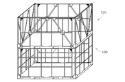
図1Aは、本発明の実施形態に係るリターナブルタイプの輸送パレット100をつま面側(長手側)から見た側面図、図1Bは側面側(短手側)から見た側面図である。この輸送パレット100は、2枚のつまパネル110と2枚の側パネル120を、矩形状の床パネル130の四辺上に垂直に立てた後に互いに連結することで、床パネル130と一体化されるようになっている。床パネル130は図示例では長方形であるが、正方形で構成することも可能である。
(Configuration of transport pallet)
FIG. 1A is a side view of a returnable transport pallet 100 according to an embodiment of the present invention as viewed from the toe surface side (longitudinal side), and FIG. 1B is a side view from the side surface side (short side). The transport pallet 100 is integrated with the floor panel 130 by vertically connecting two toe panels 110 and two side panels 120 on four sides of the rectangular floor panel 130 and then connecting them to each other. It is like that. The floor panel 130 is rectangular in the illustrated example, but it may be configured as a square.

床パネル130には、フォークリフトの2本の爪を差し込むための2つの長方形の穴部132がつま側に形成されている。床パネル130の形状(例えば正方形)によっては、当該穴部132を床パネル130の四方に形成することでフォークリフトの四方差しも可能である。 In the floor panel 130, two rectangular holes 132 for inserting the two claws of the forklift are formed on the toe side. Depending on the shape (for example, square) of the floor panel 130, the forklift can be inserted in four directions by forming the hole 132 in the four directions of the floor panel 130.

つまパネル110と側パネル120は、図1Aと図1Bの例では、角パイプや形鋼等の鋼材を格子状に組み合わせて構成している。当該格子状は一例であって、つまパネル110と側パネル120の構成は任意である。例えばつまパネル110と側パネル120は、斜め材を追加的に組み合わせて構成することも可能である。また、矩形状フレーム枠の内側に波板鋼板を配置した構造にしてもよい。 In the example of FIG. 1A and FIG. 1B, the toe panel 110 and the side panel 120 are configured by combining steel materials such as square pipes and shaped steel in a lattice shape. The lattice shape is an example, and the configuration of the toe panel 110 and the side panel 120 is arbitrary. For example, the toe panel 110 and the side panel 120 can be configured by additionally combining diagonal materials. Moreover, you may make it the structure which has arrange | positioned the corrugated steel plate inside the rectangular frame.

図1Cは、図1Aと図1Bの格子状のバネルを使用した輸送パレット100(下段)と、斜め材を追加的に組み合わせたパネルを使用した輸送パレット100(上段)を二段積みした状態を示している。このように、つまパネル110と側パネル120の構成は任意である。 FIG. 1C shows a state in which the transport pallet 100 (lower stage) using the lattice-like panel of FIGS. 1A and 1B and the transport pallet 100 (upper stage) using a panel in which diagonal materials are additionally combined are stacked in two stages. Show. Thus, the structure of the toe panel 110 and the side panel 120 is arbitrary.

輸送パレット100は段積み可能に構成されている。当該段積みのために、図1D(a)(b)のように、側パネル120の柱部材121の上端部に固定された上端コーナ金具20の上に半球状凸部21が形成され、当該凸部21に対応して床パネル130の四隅部下面に円形穴部131が形成されている。そして輸送パレット100を段積みすると、下段の輸送パレット100の半球状凸部凸部21が上段の輸送パレット100の床パネル130の円形穴部131に嵌合してパレット100相互の位置ズレが防止されるようになっている。 The transport pallet 100 is configured to be stacked. For the stacking, as shown in FIGS. 1D (a) and 1 (b), a hemispherical convex portion 21 is formed on the upper end corner metal fitting 20 fixed to the upper end portion of the column member 121 of the side panel 120. A circular hole 131 is formed in the bottom surface of the four corners of the floor panel 130 corresponding to the convex portion 21. When the transport pallets 100 are stacked, the hemispherical convex portions 21 of the lower transport pallet 100 are fitted into the circular holes 131 of the floor panel 130 of the upper transport pallet 100, thereby preventing misalignment between the pallets 100. It has come to be.

パレット100の側壁を構成する4枚のパネル110、120は、床パネル130上に重ねて置くことができる。図2Aは、2枚のつまパネル110を床パネル130から取り外して、床パネル130上に重ねた状態を示している。 The four panels 110 and 120 constituting the side wall of the pallet 100 can be placed on the floor panel 130 in an overlapping manner. FIG. 2A shows a state where the two toe panels 110 are removed from the floor panel 130 and stacked on the floor panel 130.

図2Bは、当該2枚重ねのつまパネル110の上に、2枚の側パネル120を内側に倒して重ね合わせた状態を示している。2枚の側パネル120は互いに上框を突き合わせた状態で配置されているが、床パネル130の形状及び側パネル120の高さによっては、2枚の側パネル120を上下段違い状に重ね合わせることも可能である。図2Bの折畳み状態で、図2Cのように、複数の輸送パレット100を段積みすることが可能である。 FIG. 2B shows a state in which the two side panels 120 are folded inward and superimposed on the two-stacked toe panel 110. The two side panels 120 are arranged in a state in which their upper collars are in contact with each other. However, depending on the shape of the floor panel 130 and the height of the side panel 120, the two side panels 120 may be stacked in a stepped manner. Is also possible. In the folded state of FIG. 2B, a plurality of transport pallets 100 can be stacked as shown in FIG. 2C.

また、図2Dのように、床パネル130の四隅部のコーナー金具30の四隅ポスト31のL字状上端部が、上側の床パネル130の四隅部下部外側に嵌まり込むように構成されている。四隅ポスト31は図2Eのように所定の厚みを有するスペーサー金具29を介して床パネル130の角部に溶接されている。 Further, as shown in FIG. 2D, the L-shaped upper ends of the four corner posts 31 of the corner metal fittings 30 at the four corners of the floor panel 130 are configured to fit into the lower outer sides of the four corners of the upper floor panel 130. . The four corner posts 31 are welded to the corners of the floor panel 130 through spacer fittings 29 having a predetermined thickness as shown in FIG. 2E.

スペーサー金具29はパレット100の段積み及び分離をスムーズにするためのもので、スペーサー金具29の厚み分だけ上側の床パネル130の四隅部と四隅ポスト31との間に適度の間隙が形成される。これにより、上下のパレット100の水平方向の位置ずれ・ガタツキを最小限にすると共に、パレット100のスムーズな段積み及び分離が可能になる。 The spacer metal fittings 29 are for smooth stacking and separation of the pallets 100, and an appropriate gap is formed between the four corners of the upper floor panel 130 and the four corner posts 31 by the thickness of the spacer metal fittings 29. . As a result, horizontal displacement and backlash of the upper and lower pallets 100 can be minimized, and the pallets 100 can be stacked and separated smoothly.

図3Aは床パネル130のコーナー金具30の斜視図である。このコーナー金具30は床パネル130の四隅部上に溶接付けされている。コーナー金具30は、平面視でL字状を成す四隅ポスト31と、当該四隅ポスト31の一方の縦壁部31aの内面に固定されたプレート材32、33で構成されている。 FIG. 3A is a perspective view of the corner fitting 30 of the floor panel 130. The corner fittings 30 are welded onto the four corners of the floor panel 130. The corner metal fitting 30 is composed of a four-corner post 31 having an L shape in plan view, and plate members 32 and 33 fixed to the inner surface of one vertical wall portion 31a of the four-corner post 31.

一方のプレート材32は、水平方向(床パネル130の「つま側」中央方向)に張り出した凸部32aと、当該凸部32aから床パネル130の角部に向かって上り傾斜(例えば約15°)したガイド部32bと、当該ガイド部32bの終端に短い水平部32b1を介して隣接した円弧状凹部32cと、前記凸部32aから床パネル130の角部に向かって下り傾斜(例えば約15°)したガイド部32dと、当該ガイド部32dの終端から垂直下方に延びたガイド部32eとを有する。上り傾斜のガイド部32bの方が、下り傾斜のガイド部32dよりも、水平方向の長さがやや長くされている。水平部32b1の両端部は、必要に応じて適当な曲率半径の円弧状に形成することができる。また当該水平部32b1を含むガイド部32b全体を、適当な曲率半径の円弧状に形成してもよい。 One plate member 32 has a convex portion 32a projecting in the horizontal direction (the center direction of the “toe side” of the floor panel 130) and an upward slope (for example, about 15 ° from the convex portion 32a toward the corner portion of the floor panel 130). ), The arcuate concave portion 32c adjacent to the end of the guide portion 32b via a short horizontal portion 32b1, and a downward slope from the convex portion 32a toward the corner of the floor panel 130 (for example, about 15 °). ) And a guide portion 32e extending vertically downward from the end of the guide portion 32d. The upward inclined guide part 32b is slightly longer in the horizontal direction than the downward inclined guide part 32d. Both ends of the horizontal portion 32b1 can be formed in an arc shape with an appropriate curvature radius as required. Further, the entire guide portion 32b including the horizontal portion 32b1 may be formed in an arc shape having an appropriate curvature radius.

他方のプレート材33は、前記下り傾斜のガイド部32dと平行状に対向して傾斜したガイド部33aと、当該ガイド部33aの下り側終端から垂直下方に延びたガイド部33bとを有する。そして図4Cのように、傾斜したガイド部32dと33aの相互間に傾斜溝34が形成され、垂直下方に延びたガイド部32eと33bの相互間に垂直溝35が形成されている。 The other plate member 33 has a guide portion 33a inclined in parallel with the downwardly inclined guide portion 32d, and a guide portion 33b extending vertically downward from the lower end of the guide portion 33a. 4C, an inclined groove 34 is formed between the inclined guide portions 32d and 33a, and a vertical groove 35 is formed between the guide portions 32e and 33b extending vertically downward.

傾斜溝34と垂直溝35の溝幅は、丸棒部材40が通過可能なように、その直径よりも僅かに大きく設定されている。前記傾斜溝34は床パネル130に対する垂直方向から所定角度で傾斜しており、当該「所定角度」は、後述する凸部50の出し入れをスムーズに行える、例えば30°、45°、60°などの任意の角度である。また垂直溝35の上下方向の長さ(高さ)は、後述するように、側パネル120を引き起こす際に、側パネル120の凸部50の円弧状下端部が円弧状凹部32cに嵌り込むと同時に、丸棒部材40が垂直溝35の下端部に落下して嵌り込むのを可能にする長さである。 The groove width of the inclined groove 34 and the vertical groove 35 is set to be slightly larger than the diameter so that the round bar member 40 can pass therethrough. The inclined groove 34 is inclined at a predetermined angle with respect to the vertical direction with respect to the floor panel 130, and the “predetermined angle” can smoothly insert and remove the convex portion 50 described later, for example, 30 °, 45 °, 60 °, etc. Any angle. The vertical length (height) of the vertical groove 35 is such that, as will be described later, when the side panel 120 is raised, the arcuate lower end of the projection 50 of the side panel 120 fits into the arcuate recess 32c. At the same time, the length allows the round bar member 40 to fall and fit into the lower end of the vertical groove 35.

側パネル120を折り畳んだ状態では、図3B及び図3Cに示すように、左右の側パネル120の左右一対の柱部材121の基端部に溶接付けされた回転支点部としての丸棒部材40が、ガタツキのない僅かな隙間を残した状態で垂直溝35の下端部に回転可能に嵌め込まれている。この嵌め込み状態において、前記四隅ポスト31の一方の縦壁部31aが、側パネル120の左右一対の丸棒部材40の両外側に位置している。これにより、パレット100を折り畳んで(特に段積み状態で)トラックで輸送したり、フォークリフトで搬送したりする際の、側パネル120の水平方向(前後・左右方向)のガタツキ・アバレを規制することができる。 In the state in which the side panel 120 is folded, as shown in FIGS. 3B and 3C, the round bar member 40 as a rotation fulcrum portion welded to the base end portion of the pair of left and right column members 121 of the left and right side panels 120 is provided. The vertical groove 35 is rotatably fitted in the lower end of the vertical groove 35 while leaving a slight gap without backlash. In this fitted state, one vertical wall portion 31 a of the four corner post 31 is located on both outer sides of the pair of left and right round bar members 40 of the side panel 120. By this, the horizontal (front / rear / left / right) rattling / abare of the side panel 120 when the pallet 100 is folded (particularly in a stacked state) and transported by truck or transported by forklift is regulated. Can do.

四隅ポスト31の内側の一方のプレート材32に形成された上り傾斜のガイド部32bは、パレット組み立てのため側パネル120を立ち上げる際に、当該側パネル120の柱部材121の基端部外側面に溶接付けされた係合部としての凸部50をガイドするためのものである。この凸部50の下端部の形状は、プレート材32の前記円弧状凹部32cと同じように円弧状とされ、当該円弧状の形で柱部材121の外側面から側方に所定幅で隆起している。 When the side panel 120 is raised for assembling the pallet, the upwardly inclined guide portion 32b formed on the one plate member 32 inside the four corner posts 31 is the outer surface of the base end portion of the column member 121 of the side panel 120. It is for guiding the convex part 50 as an engaging part welded to. The shape of the lower end portion of the convex portion 50 is an arc shape similar to the arc-shaped concave portion 32c of the plate member 32, and protrudes laterally from the outer surface of the column member 121 in the arc shape. ing.

前記円弧状凹部32cは上方に向かって開口し、図4Cに示すように、側パネル120の凸部50が上方から円弧状凹部32cに嵌入可能に構成されている。側パネル120の凸部50が円弧状凹部32cに嵌入することで、側パネル120の自立機能が働く。 The arc-shaped recess 32c opens upward, and as shown in FIG. 4C, the convex portion 50 of the side panel 120 is configured to be fitted into the arc-shaped recess 32c from above. The self-standing function of the side panel 120 works because the convex part 50 of the side panel 120 fits into the circular arc-shaped concave part 32c.

(側パネルの引き起こし)
次に、輸送パレット100の組み立てのために側パネル120を引き起こす際の作動を図4Cを参照して説明する。床パネル130上に水平状に倒伏して置かれた側パネル120を、図4Cの矢印方向に引き起こすと、側パネル120の左右の柱部材121の基端部に位置する丸棒部材40を回転支点として、側パネル120が上方に回転する。丸棒部材40は垂直溝35内に回転可能に保持されているので、図4Cの実線で示す丸棒部材40の位置を定位置として側パネル120が回転する。
(Cause of side panel)
Next, the operation of causing the side panel 120 to assemble the transport pallet 100 will be described with reference to FIG. 4C. When the side panel 120 lying down horizontally on the floor panel 130 is raised in the direction of the arrow in FIG. 4C, the round bar member 40 positioned at the base end of the left and right column members 121 of the side panel 120 is rotated. As a fulcrum, the side panel 120 rotates upward. Since the round bar member 40 is rotatably held in the vertical groove 35, the side panel 120 rotates with the position of the round bar member 40 shown by the solid line in FIG. 4C as a fixed position.

側パネル120を丸棒部材40を中心としてある程度上方に回転させると、側パネル120の凸部50の下端部が上り傾斜のガイド部32bに当接する。そして、この当接状態からさらに側パネル120を図4Cで右方向に回転させると、凸部50の円弧状下端部がガイド部32bに沿って上り摺動する間に、丸棒部材40が一点鎖線で示すように垂直溝35内で一方のプレート材33の垂直なガイド部33bを擦りながら上昇する。 When the side panel 120 is rotated upward about the round bar member 40 to some extent, the lower end portion of the convex portion 50 of the side panel 120 comes into contact with the upwardly inclined guide portion 32b. When the side panel 120 is further rotated to the right in FIG. 4C from this contact state, the round bar member 40 is moved to one point while the arc-shaped lower end portion of the convex portion 50 slides up along the guide portion 32b. As indicated by the chain line, the vertical guide 35 is raised while rubbing the vertical guide portion 33b of one plate member 33 in the vertical groove 35.

つまり、上り傾斜のガイド部32bによる案内作用(一種のカム作用)によって、側パネル120の基端部が床パネル130から浮き上がるのであるが、これは側パネル120を引き起こす回転モーメントの一部を、てこの作用で、側パネル120の上昇力(持ち上げ力)に変換した結果でもある。したがって、作業者は側パネル120の重量を特に意識することなく、側パネル120を回転させつつ垂直方向に楽に浮き上がらせることができる。 In other words, the base end portion of the side panel 120 is lifted from the floor panel 130 by the guiding action (a kind of cam action) by the upwardly inclined guide part 32b, but this is a part of the rotational moment that causes the side panel 120, This is also the result of converting the lifting force (lifting force) of the side panel 120 by the lever action. Therefore, the operator can easily float in the vertical direction while rotating the side panel 120 without being particularly aware of the weight of the side panel 120.

そして側パネル120をほぼ垂直状態まで回転させると、側パネル120の凸部50の円弧状下端部が、ガイド部32bを通り越して円弧状凹部32cに嵌り込む。またこの嵌り込んだ状態で、側パネル120の下端部122が床パネル130の上面に当接すると共に、垂直なガイド部33bを擦りながらそれまで上昇していた丸棒部材40が再び垂直溝35の下端部に落下して嵌り込む。 When the side panel 120 is rotated to a substantially vertical state, the arc-shaped lower end portion of the convex portion 50 of the side panel 120 passes through the guide portion 32b and fits into the arc-shaped concave portion 32c. Further, in this fitted state, the lower end portion 122 of the side panel 120 abuts on the upper surface of the floor panel 130, and the round bar member 40 that has been raised while rubbing the vertical guide portion 33b again becomes the vertical groove 35. Drop and fit into the lower end.

つまり、凸部50の円弧状下端部が円弧状凹部32cに嵌り込んだ途端に、側パネル120が図4Cの矢印方向に突然下降するので、作業者はその時に発生する音と振動で側パネル120が自立可能状態になったことを確認することができる。また、当該自立可能状態においては、側パネル120を垂直上方に引き抜くことが不可能になる。 That is, as soon as the arc-shaped lower end of the convex portion 50 is fitted into the arc-shaped recess 32c, the side panel 120 suddenly descends in the direction of the arrow in FIG. 4C. It can be confirmed that the panel 120 is in a self-supporting state. Further, in the self-supporting state, it is impossible to pull out the side panel 120 vertically upward.

すなわち、丸棒部材40が垂直溝35の下端部に嵌り込んでいる状態では、当該丸棒部材40の上方にプレート材32の下り傾斜のガイド部32dが位置しているので、側パネル120を垂直上方に引き抜こうとしても、丸棒部材40が当該ガイド部32dに当接する。したがって、それ以上は側パネル120を垂直上方に引き抜くことが不可能になる。 That is, in the state where the round bar member 40 is fitted in the lower end portion of the vertical groove 35, the downwardly inclined guide portion 32 d of the plate material 32 is located above the round bar member 40. Even if it is going to be pulled out vertically upward, the round bar member 40 comes into contact with the guide portion 32d. Accordingly, it becomes impossible to pull the side panel 120 vertically upward.

このように、後述するハンドルラッチ80でつまパネル110を側パネル120にロックする前でも、側パネル120の垂直上方の引き抜きが不能になるから、つまパネル110の浮き上がりを阻止する床パネル130の傾斜板部60bは、必ずしも内側に傾斜させる必要はない。傾斜板部60bを垂直板部に変更することで、つまパネル110の立て掛けを容易化することも可能である。つまり、つまパネル110を上方に引き抜き可能に構成することも可能である。 In this way, even if the toe panel 110 is locked to the side panel 120 by the handle latch 80 described later, the side panel 120 cannot be pulled out vertically, so that the inclination of the floor panel 130 that prevents the toe panel 110 from being lifted up. The plate portion 60b is not necessarily inclined inward. By changing the inclined plate portion 60b to a vertical plate portion, it is possible to facilitate the leaning of the toe panel 110. That is, it is also possible to configure the toe panel 110 so that it can be pulled out upward.

以上は、床パネル130上に水平状に置かれた側パネル120をそのまま回転させて立ち上げる場合の操作であるが、床パネル130上に載せる貨物の種類によっては、側パネル120を外した状態で当該貨物を床パネル上でバンド掛け等をしたい場合がある。このバンド掛けの場合、作業者は床パネル130の周縁を移動しなからバンド掛けをするので、側パネル120が立っていると邪魔になるのである。 The above is the operation when the side panel 120 placed horizontally on the floor panel 130 is rotated and started up as it is, but depending on the type of cargo loaded on the floor panel 130, the side panel 120 is removed. In some cases, you may want to band the cargo on the floor panel. In the case of this banding, the operator performs banding without moving the peripheral edge of the floor panel 130, so it becomes an obstacle when the side panel 120 stands.

このような場合は、側パネル120を自立状態で立て掛けないで、側パネル120を回転させて立ち上げた後に当該側パネル120を持ち上げて少し浮かせた状態にし、その状態で下端部の丸棒部材40を垂直溝35と傾斜溝34を通して上方に抜き出すことで側パネル120を床パネル130から取り外す。或いは、水平状の側パネル120を手で持って少し上方に浮かせてその丸棒部材40を垂直溝35と傾斜溝34を通して上方に抜き出し、そのまま水平方向に移動する。 In such a case, the side panel 120 is not stood up in a self-standing state, the side panel 120 is rotated and raised, and then the side panel 120 is lifted and slightly floated, and in this state, the round bar member at the lower end portion The side panel 120 is removed from the floor panel 130 by pulling 40 upward through the vertical groove 35 and the inclined groove 34. Alternatively, the horizontal side panel 120 is held by hand and floated slightly upward, and the round bar member 40 is extracted upward through the vertical groove 35 and the inclined groove 34 and moved in the horizontal direction as it is.

このようにして、側パネル120を床パネル130上から簡単に除去することができる。取り外した側パネル120は、床パネル130の横の空きスペース等に一時的に置いておく。そして貨物のバンド掛けが終了した後、側パネル120を床パネル130の縁に戻して立て掛ける。 In this way, the side panel 120 can be easily removed from the floor panel 130. The removed side panel 120 is temporarily placed in an empty space or the like next to the floor panel 130. After the cargo banding is completed, the side panel 120 is returned to the edge of the floor panel 130 and leaned.

この立て掛けの際、側パネル120を図4Cの右側から三番目のようにやや斜めに倒した状態にして、その下端部の丸棒部材40を図4Cの傾斜溝34を通して垂直溝35の下端部に嵌め込む。そして、側パネル120を当該斜めの状態から矢印方向に回転させて垂直状に立ち上げる。 At the time of this leaning, the side panel 120 is tilted slightly obliquely from the right side of FIG. 4C, and the round bar member 40 at the lower end thereof is passed through the inclined groove 34 of FIG. Fit into. Then, the side panel 120 is rotated in the direction of the arrow from the oblique state to rise up vertically.

これにより、側パネル120の柱部材121の下端部が床パネル130上に当接し、同時に、柱部材121の基端部外側面の凸部50の円弧状下端部が、床パネル130の四隅ポスト31の内側に配設されたプレート材32の凹部32cに嵌合する。これで側パネル120が自立可能状態になる。この自立可能状態で、側パネル120は垂直上方に引き抜き不能となる。すなわち、垂直溝35に嵌った丸棒部材40は、その上方に傾斜溝34があるので、側パネル120を垂直上方に引き抜こうとしても、丸棒部材40が傾斜溝34の縁(下り傾斜のガイド部32d)に当接するので、側パネル120の垂直上方への引き抜きが阻止される。 Accordingly, the lower end portion of the column member 121 of the side panel 120 abuts on the floor panel 130, and at the same time, the arc-shaped lower end portion of the convex portion 50 on the outer surface of the base end portion of the column member 121 is the four corner posts of the floor panel 130. It fits into the recess 32 c of the plate material 32 disposed inside 31. Thus, the side panel 120 is in a state where it can stand on its own. In this self-supporting state, the side panel 120 cannot be pulled out vertically upward. That is, since the round bar member 40 fitted in the vertical groove 35 has the inclined groove 34 above the round bar member 40, even if the side panel 120 is pulled out vertically upward, the round bar member 40 does not move the Since it abuts on the guide portion 32d), the side panel 120 is prevented from being pulled out vertically upward.

側パネル120は前述のように垂直上方への引き抜きが阻止される構造ではあるが、輸送中の輸送パレット100の振動や衝撃等によって丸棒部材40が傾斜溝34に沿って不測に斜め上方に移動する可能性はゼロではない。そこで本実施形態では図4Dのように、つまパネル110の柱部材111にストッパー部115を設けている。 As described above, the side panel 120 has a structure that prevents the upward pulling in the vertical direction. However, the round bar member 40 is unexpectedly inclined upward along the inclined groove 34 due to vibration or impact of the transportation pallet 100 during transportation. The possibility of moving is not zero. Therefore, in the present embodiment, as shown in FIG. 4D, the stopper portion 115 is provided on the column member 111 of the toe panel 110.

このストッパー部115の形状は、つまパネル110を立て掛けた状態において、その柱部材111の下端部に近い側面(基端部)から、側パネル120の柱部材121の基端部に向けて、水平方向に突出した横長長方形板状である。そして当該ストッパー部115の先端部115aが柱部材121の側面に当接することで、側パネル120の下端部(基端部)が内側方向に不測に移動して丸棒部材40が傾斜溝34に沿って上方に移動するのを確実に阻止する。 The shape of the stopper portion 115 is such that, in a state where the toe panel 110 is leaned up, the side surface (base end portion) near the lower end portion of the column member 111 is horizontally directed toward the base end portion of the column member 121 of the side panel 120. It is a horizontally long rectangular plate protruding in the direction. Then, when the distal end portion 115a of the stopper portion 115 abuts against the side surface of the column member 121, the lower end portion (base end portion) of the side panel 120 moves unexpectedly inwardly, so that the round bar member 40 becomes the inclined groove 34. To prevent it from moving upwards along.

(つまパネルの立て掛け)
図5A〜図5Cは、床パネル130上につまパネル110を立て掛ける構造を示している。床パネル130のつま面側縁部には、複数の浮き止め金具60が所定間隔で溶接付けされている。当該浮き止め金具60は、床パネル130の外側面に溶接付けされた垂直板部60aと、当該垂直板部60aの上端部から床パネル130の内側斜め方向に延びた傾斜板部60bで構成されている。
(Steel panel leaning)
5A to 5C show a structure in which the toe panel 110 is leaned on the floor panel 130. A plurality of floating metal fittings 60 are welded to the edge portion of the floor surface of the floor panel 130 at predetermined intervals. The floating metal fitting 60 is composed of a vertical plate portion 60a welded to the outer surface of the floor panel 130, and an inclined plate portion 60b extending in an obliquely inward direction of the floor panel 130 from the upper end portion of the vertical plate portion 60a. ing.

また、浮き止め金具60の内側面に対向するようにして、床パネル130上に垂直板部62が溶接付けされている。当該垂直板部62は、図示例ではつま側の長手方向に連続して形成されているが、所定間隔で複数配置してもよい。つまパネル110を立て掛けるには、つまパネル110を外側に開いた傾斜状態で、その下框114の断面L型の水平板部114aを、床パネル130の浮き止め金具60と垂直板部62の間に嵌め込む。 In addition, the vertical plate portion 62 is welded onto the floor panel 130 so as to face the inner side surface of the floating metal fitting 60. In the illustrated example, the vertical plate portion 62 is continuously formed in the longitudinal direction of the toe side, but a plurality of the vertical plate portions 62 may be arranged at a predetermined interval. In order to lean the toe panel 110, with the toe panel 110 opened to the outside, the L-shaped horizontal plate portion 114a of the lower collar 114 is placed between the floating bracket 60 and the vertical plate portion 62 of the floor panel 130. Fit into.

この状態で、つまパネル110の下框114の左右両端部には、プレート材33が隣接して位置している。したがって、当該プレート材33によってつまパネル110の横ズレが規制される。このように横ズレが規制された状態のつまパネル110を、そのまま垂直状態まで立て掛けることで、パネル110を仮置き状態にすることができる。 In this state, the plate material 33 is positioned adjacent to the left and right ends of the lower collar 114 of the toe panel 110. Accordingly, the lateral displacement of the toe panel 110 is regulated by the plate material 33. Thus, the panel 110 can be put into a temporarily placed state by leaning the toe panel 110 in a state where the lateral displacement is restricted to the vertical state as it is.

この仮置き状態では、床パネル130の傾斜板部60bがつまパネル110の下框114の水平板部114aを抑える形になっているので、つまパネル110を上方に向けて引き抜くことは不可能な状態になっている。但し、つまパネル110から手を離すとつまパネル110が自然に外側に倒れる可能性がある。そこで、つまパネル110をハンドルラッチ80で側パネル120にロックするまでの間、後述するように、つまパネル110を凸部112aによって側パネル120に仮止めする。なお、当該傾斜板部60bは前述したように垂直板部に変更可能であり、つまパネル110を上方に引き抜き可能に構成することも可能である。 In this temporarily placed state, since the inclined plate portion 60b of the floor panel 130 is configured to restrain the horizontal plate portion 114a of the lower collar 114 of the toe panel 110, it is impossible to pull the toe panel 110 upward. It is in a state. However, when the hand is released from the toe panel 110, the toe panel 110 may fall down naturally. Therefore, until the toe panel 110 is locked to the side panel 120 by the handle latch 80, the toe panel 110 is temporarily fixed to the side panel 120 by the convex portion 112a as described later. The inclined plate portion 60b can be changed to a vertical plate portion as described above, and the hook panel 110 can be configured to be pulled out upward.

(ハンドルラッチの構成・作用)
次に、図6A〜図6Dを参照してハンドルラッチ80について説明する。このハンドルラッチ80は、床パネル130上に垂直状態に仮置きした2枚のつまパネル110を、自立している2枚の側パネル120に対して係合させるものである。ハンドルラッチ80を掛けることで、つまパネル110と側パネル120とが一体化され、4枚すべてのパネルが床パネル130から浮き上がることなく垂直状に自立する。4枚の側壁パネルの浮き上がりを規制しているのは、床パネル130の傾斜板部60bである。
(Structure / action of handle latch)
Next, the handle latch 80 will be described with reference to FIGS. 6A to 6D. The handle latch 80 engages the two toe panels 110 temporarily placed on the floor panel 130 in a vertical state with the two standing side panels 120. By hooking the handle latch 80, the toe panel 110 and the side panel 120 are integrated, and all four panels are self-supporting without being lifted from the floor panel 130. It is the inclined plate portion 60b of the floor panel 130 that regulates the lifting of the four side wall panels.

ハンドルラッチ80は、2枚のつまパネル110の左右両端に1つずつ、合計で4つ備えられている。ハンドルラッチ80は水平方向にスライド可能な係合ロッド81を有し、当該係合ロッド81の両端部分は、つまパネル110の柱部材111に成形された挿通穴と、支持板90の挿通穴とに、それぞれスライド可能に支持されている。 A total of four handle latches 80 are provided, one at each of the left and right ends of the two toe panels 110. The handle latch 80 has an engaging rod 81 that is slidable in the horizontal direction, and both end portions of the engaging rod 81 are an insertion hole formed in the column member 111 of the toe panel 110 and an insertion hole of the support plate 90. In addition, each is slidably supported.

また、つまパネル110の上框112の両端部には、後述する丸穴23に嵌合可能な円柱状の短い凸部112aが、上框112の長手方向に突出した状態で溶接付けされている。当該凸部112aは、つまパネル110と側パネル120の位置ズレを規制する機能と、つまパネル110が外側に自然に倒れないように、つまパネル110を側パネル120に仮止めする機能を有する。凸部112aの先端面形状は、丸穴23に対するスムーズな挿入を可能にするため、例えば滑らかな球面状にすることができる。 Moreover, the column-shaped short convex part 112a which can be fitted to the round hole 23 mentioned later is welded to the both ends of the upper collar 112 of the toe panel 110 in the state which protruded in the longitudinal direction of the upper collar 112. . The convex portion 112a has a function of restricting the positional deviation between the toe panel 110 and the side panel 120 and a function to temporarily fix the toe panel 110 to the side panel 120 so that the toe panel 110 does not fall down naturally. The front end surface shape of the convex portion 112a can be, for example, a smooth spherical surface in order to enable smooth insertion into the round hole 23.

係合ロッド81の中間部には、つまパネル110の外側から操作可能なハンドル部82が、係合ロッド81の長手方向と直角に一体的に取り付けられている。このハンドル部82は金属棒をU字状に屈曲したもので、当該U字状の両方の先端部分が係合ロッド81の中間部に溶接付けされている。また、つまパネル110の柱部材から側パネル120側に突出した係合ロッド81の先端部には、係合ロッド81の長手方向に直角に屈曲されたL字状の係合部83が形成されている。 A handle portion 82 that can be operated from the outside of the toe panel 110 is integrally attached to an intermediate portion of the engagement rod 81 at a right angle to the longitudinal direction of the engagement rod 81. The handle portion 82 is formed by bending a metal rod into a U shape, and both end portions of the U shape are welded to the intermediate portion of the engagement rod 81. In addition, an L-shaped engagement portion 83 that is bent at a right angle to the longitudinal direction of the engagement rod 81 is formed at the distal end portion of the engagement rod 81 that protrudes from the column member of the toe panel 110 toward the side panel 120. ing.

一方、側パネル120の上端コーナ金具20(段積み用支持部)の側面には、前記係合ロッド81の先端部のL字状係合部83を挿入可能な縦長穴22と、当該縦長穴22の上方に位置する丸穴23が形成されている。当該丸穴23は、つまパネル110の上框両端部に配置された前述の凸部112aを嵌合するためのものである。ハンドル部82を水平に持ち上げることで、L字状係合部83を垂直(縦上向き)にした状態で前記縦長穴22に挿入することができる。 On the other hand, on the side surface of the upper end corner metal fitting 20 (the stacking support portion) of the side panel 120, a vertically long hole 22 into which the L-shaped engaging portion 83 at the tip of the engaging rod 81 can be inserted, and the vertically long hole. A round hole 23 located above 22 is formed. The said round hole 23 is for fitting the above-mentioned convex part 112a arrange | positioned at the upper collar both ends of the toe panel 110. FIG. By lifting the handle portion 82 horizontally, the L-shaped engaging portion 83 can be inserted into the vertically elongated hole 22 in a vertical state (vertically upward).

そして、縦長穴22にL字状係合部83を挿入した後、ハンドル部82から手を離すと、ハンドル部82が自重で下方に約90°回動し、係合ロッド81の先端部のL字状係合部83が、上向き位置から、ほぼ90°回転した横向き位置に変わる。これにより、L字状係合部83が縦長穴22の内側に係合して、縦長穴22からの係合ロッド81の抜き出し不能になる。 Then, after inserting the L-shaped engaging portion 83 into the vertically long hole 22, when the hand is released from the handle portion 82, the handle portion 82 rotates downward by about 90 ° under its own weight, and the tip of the engaging rod 81 The L-shaped engaging portion 83 changes from an upward position to a lateral position rotated by approximately 90 °. As a result, the L-shaped engaging portion 83 engages with the inside of the vertically long hole 22 so that the engaging rod 81 cannot be extracted from the vertically long hole 22.

支持板90には、ハンドル部82を挟んでそのスライド移動を規制するクリップ91が配置されている。このクリップ91は弾力性を有する樹脂等により略U字状に形成されたものであって、ハンドル部82のU字状のいずれか一方の部分をクリップ91に押し込むことで、係合ロッド81の横方向のスライド移動を規制して、ハンドルラッチ80をロック又はアンロック状態に固定する。ハンドル部82のU字状の一方の部分をクリップ91に押し込んだ状態(図6B)がアンロック状態で、ハンドル部82のU字状の反対部分をクリップ91に押し込んだ状態(図6D)がロック状態である。 The support plate 90 is provided with a clip 91 that restricts the slide movement with the handle portion 82 interposed therebetween. The clip 91 is formed in a substantially U shape with a resin or the like having elasticity, and by pushing one of the U-shaped portions of the handle portion 82 into the clip 91, The sliding movement in the lateral direction is restricted, and the handle latch 80 is fixed in the locked or unlocked state. A state in which one U-shaped portion of the handle portion 82 is pushed into the clip 91 (FIG. 6B) is in an unlocked state, and a state in which the opposite U-shaped portion of the handle portion 82 is pushed into the clip 91 (FIG. 6D). It is locked.

ハンドルラッチ80は、つまパネル110の左右両端に1つずつ備えられ、全部で4つのハンドルラッチ80を2枚の側パネル120の縦長穴22に係合させることで、2枚のつまパネル110を、2枚の自立した側パネル120に係合させることができる。この状態でパレット100の床パネル130上に搭載した荷物を輸送する。 One handle latch 80 is provided at each of the left and right ends of the toe panel 110, and the four handle latches 80 are engaged with the longitudinal elongated holes 22 of the two side panels 120, thereby allowing the two toe panels 110 to be engaged. It can be engaged with two free standing side panels 120. In this state, the cargo loaded on the floor panel 130 of the pallet 100 is transported.

L字状の係合部83は、ハンドルラッチ80のロック状態において、つまパネル110の柱部材111から水平方向に比較的長く延び出た係合ロッド81の先端部に配置されている。このため、従来、係合ロッド81の当該長く延び出た部分が、輸送時の輸送パレット100の揺れ等によって曲ってしまうことがあった。 The L-shaped engaging portion 83 is disposed at the distal end portion of the engaging rod 81 extending relatively long in the horizontal direction from the column member 111 of the toe panel 110 when the handle latch 80 is locked. For this reason, conventionally, the long extending portion of the engagement rod 81 may be bent due to shaking of the transportation pallet 100 during transportation.

係合ロッド81がこのように曲がると、ハンドルラッチ80の抜き差しが最早不能になることもある。本発明の実施形態では、つまパネル110の上框112の凸部112aを側パネル120のコーナー金具20の丸穴23に嵌合させることでパネル相互の位置ズレを規制し、従来、係合部83に作用していた曲げ力を凸部112aが代わって負担することが可能になる。したがって、輸送パレット100の強度アップを図ると共に、係合ロッド81やその先端係合部83の変形を防止し、ハンドルラッチ80のスムーズな抜き差しを保証することができる。 If the engagement rod 81 is bent in this way, the handle latch 80 may no longer be inserted or removed. In the embodiment of the present invention, the protrusion 112a of the upper collar 112 of the toe panel 110 is fitted into the round hole 23 of the corner metal fitting 20 of the side panel 120 to restrict the positional deviation between the panels. It becomes possible for the convex part 112a to bear the bending force acting on the 83 instead. Therefore, the strength of the transport pallet 100 can be increased, the deformation of the engagement rod 81 and its tip engagement portion 83 can be prevented, and smooth insertion and removal of the handle latch 80 can be ensured.

従来の輸送パレットは、前述のハンドルラッチ80を備えていても、ハンドルラッチ80があるつまパネル110を、側パネル120に仮止めする機構がなかった。このため、つまパネル110を片手で持って垂直状に保持した状態で、空いた方の手でハンドルラッチ80を操作してL字状係合部83を縦長穴22に係合させなければならなかった。 Even if the conventional transportation pallet is provided with the handle latch 80 described above, there is no mechanism for temporarily fixing the toe panel 110 with the handle latch 80 to the side panel 120. For this reason, in a state where the toe panel 110 is held vertically with one hand, the handle latch 80 must be operated with the free hand to engage the L-shaped engaging portion 83 with the vertically elongated hole 22. There wasn't.

この係合作業は、L字状係合部83を上向き状態で縦長穴22に挿入する作業であるが、L字状係合部83と縦長穴22との位置合わせが必ずしも容易ではなく、L字状係合部83を縦長穴22に挿入するのに手間取ることがあった。この原因の1つは、つまパネル110と側パネル120間で関連部品の寸法誤差等によって元々多少の位置ずれがあるためである。 This engagement operation is an operation of inserting the L-shaped engagement portion 83 into the vertically elongated hole 22 in an upward state, but the alignment of the L-shaped engagement portion 83 and the vertically elongated hole 22 is not always easy. It may take time to insert the character-shaped engaging portion 83 into the vertically long hole 22. One reason for this is that there is a slight misalignment between the toe panel 110 and the side panel 120 due to dimensional errors of related parts.

他の原因は、ハンドルラッチ80のロック操作に起因するものである。すなわち、1つのハンドルラッチ80をロック操作すると、当該ロック操作によって、他のハンドルラッチ80があるパネル間で位置ずれが生じ、ハンドルラッチ80のL字状係合部83と縦長穴22との位置関係が微妙にズレてしまう場合がある。実際は、このハンドルラッチ80のロック操作に起因して、L字状係合部83と縦長穴22との位置合わせがうまくいかない場合が多い。 Another cause is due to the locking operation of the handle latch 80. That is, when one handle latch 80 is locked, a position shift occurs between the panels with the other handle latch 80 due to the lock operation, and the positions of the L-shaped engaging portion 83 of the handle latch 80 and the vertically elongated hole 22 are shifted. The relationship may be slightly different. In practice, due to the locking operation of the handle latch 80, the alignment between the L-shaped engaging portion 83 and the vertically elongated hole 22 often fails.

本発明の実施形態では、まず側パネル120を弾性的にやや外側に開いた状態にして、つまパネル110の凸部112aと丸穴23の位置とが合うようにつまパネル110を垂直状に立て掛ける。そして、この立て掛け状態で側パネル120を元のように垂直状に戻す。これで凸部112aが丸穴23に確実に嵌合する。この嵌合状態では、つまパネル110から手を離しても、つまパネル110が自然に外側に倒れることがない。 In the embodiment of the present invention, first, the side panel 120 is elastically opened to the outside, and the toe panel 110 is leaned vertically so that the projection 112a of the toe panel 110 and the position of the round hole 23 are aligned. . Then, in this leaning state, the side panel 120 is returned to the original vertical shape. Thus, the convex portion 112a is securely fitted into the round hole 23. In this fitting state, even if the hand is released from the toe panel 110, the toe panel 110 does not fall down naturally.

したがって、作業者はまず輸送パレット100の各コーナー部で凸部112aを丸穴23に嵌合させ、その後に4箇所のハンドルラッチ80を順次ロック操作していけばよい。各コーナー部では凸部112aが丸穴23に嵌合して既に位置合わせが完了しているので、L字状係合部83を縦長穴22に容易に係合させることができる。したがって、従来のようにL字状係合部83を縦長穴22に挿入するのに手間取ることがない。すなわち、一箇所でハンドルラッチ80をロック操作することにより、他の箇所でハンドルラッチ80のL字状係合部83と縦長穴22との位置関係が微妙にズレてしまうことがない。 Therefore, the operator first fits the convex portion 112a into the round hole 23 at each corner portion of the transport pallet 100, and then sequentially locks the four handle latches 80. At each corner portion, the convex portion 112a is fitted into the round hole 23, and the alignment has already been completed. Therefore, the L-shaped engaging portion 83 can be easily engaged with the vertically elongated hole 22. Therefore, it does not take time to insert the L-shaped engaging portion 83 into the vertically long hole 22 as in the prior art. That is, by locking the handle latch 80 at one location, the positional relationship between the L-shaped engagement portion 83 of the handle latch 80 and the vertically elongated hole 22 does not slightly shift at other locations.

(輸送パレットの折畳み・段積み)
リターナブル輸送パレット100が輸送先に到着すると、全てのハンドルラッチ80を外す。その後、床パネル130からつまパネル110を取り外す。ハンドルラッチ80を外しても、つまパネル110の凸部112aが側パネル120のコーナー金具20に嵌合している間は、つまパネル110が自然に外側に倒れることはない。側パネル120を少し外側に押し開くとつまパネル110の凸部112aが側パネル120のコーナー金具20から外れるので、つまパネル110をやや外側に傾けながらその下框114を浮き止め金具60から外す。
(Folding and stacking of transport pallets)
When the returnable transport pallet 100 arrives at the transport destination, all the handle latches 80 are removed. Thereafter, the toe panel 110 is removed from the floor panel 130. Even if the handle latch 80 is removed, the toe panel 110 does not naturally fall outward while the convex portion 112a of the toe panel 110 is fitted to the corner fitting 20 of the side panel 120. When the side panel 120 is pushed slightly outward, the projection 112a of the toe panel 110 is detached from the corner metal fitting 20 of the side panel 120. Therefore, the lower collar 114 is removed from the floating metal fitting 60 while tilting the toe panel 110 slightly outward.

つまパネル110を取り外しても、側パネル120の凸部50が床パネル130の凹部32cに嵌合しているので、側パネル120は自立姿勢をそのまま維持している。作業者は当該側パネル120を自立したままにしておいて、床パネル130上につまパネル110を2枚重ねで載置する。その後、2枚の側パネル120を順番に内側に倒してつまパネル110の上に水平に重ね合わせる。 Even if the toe panel 110 is removed, since the convex portion 50 of the side panel 120 is fitted in the concave portion 32c of the floor panel 130, the side panel 120 maintains the self-supporting posture as it is. The worker places the side panel 120 in a self-supporting manner and places the toe panels 110 on the floor panel 130 in a stacked manner. After that, the two side panels 120 are brought down inward in order and are superposed horizontally on the toe panel 110.

この際、側パネル120は床パネル130から完全に取り外すのではなく、床パネル130から少し持ち上げてから内側に倒す。これにより側パネル120の凸部50が床パネル130の凹部32cから外れて側パネル120を内側に回転することが可能になる。 At this time, the side panel 120 is not completely removed from the floor panel 130 but is slightly lifted from the floor panel 130 and then tilted inward. Thereby, the convex part 50 of the side panel 120 can remove | deviate from the recessed part 32c of the floor panel 130, and it becomes possible to rotate the side panel 120 inside.

この側パネル120の内側方向への回転の間、側パネル120の下端部の丸棒部材40は、図4Cのように垂直溝35の下端部に位置決めされているので、側パネル120をスムーズに回転することができる。このため、側パネル120がつまパネル110に重なる水平倒伏位置も常に一定になる。したがって、折畳み状態の輸送パレット100の形態的なまとまりがよい。このようにして輸送パレット100を図2Bの折畳み状態とし、この折畳み状態の輸送パレット100を図2Cのように段積みして再利用のためにリターン輸送する。 During the rotation of the side panel 120 in the inward direction, the round bar member 40 at the lower end of the side panel 120 is positioned at the lower end of the vertical groove 35 as shown in FIG. Can rotate. For this reason, the horizontal lying position where the side panel 120 overlaps the toe panel 110 is also always constant. Therefore, the morphological unit of the transport pallet 100 in the folded state is good. In this way, the transport pallet 100 is brought into the folded state of FIG. 2B, and the folded transport pallets 100 are stacked as shown in FIG. 2C and transported in return for reuse.

(側パネルのみ取り外す方法)
図7A〜図7Dは、つまパネル110を残して側パネル120を取り外す際の方法を順を追って示す図である。このように側パネル120を取り外しておくと、複数の輸送パレット100を、各パレット100のつまパネル110を向かい合わせで一列に並べた状態にして、各輸送パレット100の床パネル130上に次々と貨物を搭載する作業が容易に行える。
(How to remove the side panel only)
7A to 7D are diagrams sequentially illustrating a method for removing the side panel 120 while leaving the toe panel 110. When the side panel 120 is removed in this way, the plurality of transport pallets 100 are arranged in a row with the toe panels 110 of each pallet 100 facing each other, and successively on the floor panel 130 of each transport pallet 100. Cargo loading work can be done easily.

図7Aは左右のハンドルラッチ80をロックした状態の輸送パレット100である。この状態から図7Bのように右側のハンドルラッチ80のみを外す。右側のハンドルラッチ80を外しても右側の側パネル120は自立状態を維持し、そのままでは内側及び外側に倒すことができない。この自立状態から、図7Bのように側パネル120を垂直上方に少し持ち上げる。すると円弧状凹部32cに自立のため嵌合していた凸部50が当該凹部32cの上方へと離脱する。 FIG. 7A shows the transport pallet 100 with the left and right handle latches 80 locked. From this state, only the right handle latch 80 is removed as shown in FIG. 7B. Even if the right handle latch 80 is removed, the right side panel 120 maintains a self-supporting state and cannot be tilted inward or outward as it is. From this self-supporting state, the side panel 120 is slightly lifted vertically upward as shown in FIG. 7B. Then, the convex part 50 fitted for self-standing in the circular arc-shaped concave part 32c is detached above the concave part 32c.

次に図7Cのように側パネル120の下端部の丸棒部材40を傾斜溝34へと逃しながら側パネル120を少し外側に傾斜させる。この傾斜状態で、図7Dのように側パネル120を斜め上方に引き抜く。そうすると、丸棒部材40がプレート材32の凸部32aとその上方にあるストッパー部115との間を斜めに通過するので、側パネル120を斜め上方に引き抜くことができる。 Next, as shown in FIG. 7C, the side panel 120 is slightly tilted outward while the round bar member 40 at the lower end of the side panel 120 escapes into the inclined groove 34. In this inclined state, the side panel 120 is pulled out obliquely upward as shown in FIG. 7D. Then, since the round bar member 40 obliquely passes between the convex portion 32a of the plate member 32 and the stopper portion 115 located above the convex portion 32a, the side panel 120 can be pulled out obliquely upward.

このようにして、左右の側パネル120の少なくとも一方を取り外し、残りのパネルは立てたままにしておくことで、貨物の搭載及び梱包作業を省作業スペースで短時間で能率よく行うことができる。 In this way, by removing at least one of the left and right side panels 120 and leaving the remaining panels standing, loading and packing operations of cargo can be efficiently performed in a short work space.

以上、本発明の実施形態について説明したが、本発明は前記実施形態に限定されることなく種々の変形が可能である。例えば前記実施形態では側パネル120をその基端部の回転支点部を中心として床パネル130側に倒伏可能に構成したが、つまパネル110を同様の構造で床パネル130側に倒伏可能に構成することも可能である。また、側パネル120を自立させる凸部50と円弧状凹部32cの配置を入れ換えて、凸部50を床パネル130側に形成し、円弧状凹部32cを側パネル120側に配設してもよい。また前記実施形態では、つまパネル110の上框112に凸部112aを形成し、相手側の側パネル120のコーナー金具20に丸穴23を形成したが、これを反対にして、上框112に丸穴23を形成し、コーナー金具20に凸部112aを形成してもよい。 As mentioned above, although embodiment of this invention was described, this invention can be variously deformed without being limited to the said embodiment. For example, in the above-described embodiment, the side panel 120 is configured to be able to fall on the floor panel 130 side with the rotation fulcrum at the base end thereof as the center. It is also possible. In addition, the arrangement of the convex portion 50 and the arc-shaped concave portion 32c for allowing the side panel 120 to stand independently may be interchanged so that the convex portion 50 is formed on the floor panel 130 side and the arc-shaped concave portion 32c is disposed on the side panel 120 side. . Moreover, in the said embodiment, although the convex part 112a was formed in the upper collar 112 of the toe panel 110, and the round hole 23 was formed in the corner metal fitting 20 of the other party side panel 120, this is reversed, The round hole 23 may be formed, and the convex portion 112 a may be formed on the corner metal fitting 20.

10:穴部 20:コーナー金具
21:突起部 22:縦長穴
23:丸穴 30:コーナー金具
31:四隅ポスト 31a:縦壁部
31a1:縦縁 31b:円弧状角部
31c:円弧状凹部 32:プレート材
33:プレート材 34:傾斜溝
35:垂直溝 40:丸棒部材(回転支点部)
50:凸部 60:金具
60a:垂直板部 60b:傾斜板部
62:垂直板部 80:ハンドルラッチ
81:係合ロッド 82:ハンドル部
83:係合部 90:支持板
91:クリップ 100:輸送パレット
110:つまパネル 111:柱部材
112:上框 112a:凸部
114:下框 114a:水平板部
120:側パネル 121:柱部材
122:下端部 130:床パネル
132:穴部
10: Hole 20: Corner fitting 21: Protruding portion 22: Long hole 23: Round hole 30: Corner fitting 31: Four corner post 31a: Vertical wall portion 31a1: Vertical edge 31b: Arc-shaped corner 31c: Arc-shaped recess 32: Plate material 33: Plate material 34: Inclined groove 35: Vertical groove 40: Round bar member (rotating fulcrum)
50: convex portion 60: metal fitting 60a: vertical plate portion 60b: inclined plate portion 62: vertical plate portion 80: handle latch 81: engagement rod 82: handle portion 83: engagement portion 90: support plate 91: clip 100: transport Pallet 110: Toe panel 111: Column member 112: Upper rod 112a: Convex portion 114: Lower rod 114a: Horizontal plate portion 120: Side panel 121: Column member 122: Lower end portion 130: Floor panel 132: Hole portion

Claims (6)

矩形状床パネルの四辺に側壁パネルがそれぞれ着脱可能に立設される輸送パレットであって、
対向する少なくとも2枚の側壁パネルが立設状態から前記床パネル側に倒伏可能なようにその基端部に配設された回転支点部が前記床パネルに対して回転可能に載置され、当該2枚の側壁パネルの柱部材の基端部の側面に形成された係合部が、当該2枚の側壁パネルの立設状態で、前記床パネルの四隅部に配設されたコーナー金具の被係合部に上方から嵌合することで当該2枚の側壁パネルが内側方向及び外側方向に回転不能な自立可能状態になるように構成し、
前記2枚の側壁パネルを前記回転支点部を中心として起立回転させて前記自立可能状態にする際に、前記係合部が摺動可能な上り傾斜のガイド部が前記コーナー金具の前記被係合部に隣接して形成され、
前記床パネル上に載置された前記回転支点部をその軸線方向と直角方向で前記床パネル上に対して出し入れ可能にするため、前記床パネルに対する垂直方向から所定角度で傾斜した傾斜溝が前記コーナー金具に形成されている、ことを特徴とする輸送パレット。
A transportation pallet in which side wall panels are detachably mounted on four sides of a rectangular floor panel,
A rotating fulcrum portion disposed at a base end portion of the at least two side wall panels facing each other so as to be able to fall on the floor panel side from a standing state is rotatably mounted on the floor panel, Engagement portions formed on the side surfaces of the base end portions of the pillar members of the two side wall panels are covered with corner metal fittings disposed at the four corners of the floor panel in the standing state of the two side wall panels. The two side wall panels are configured to be in a self-supportable state in which the two side wall panels cannot rotate in the inner and outer directions by fitting into the engaging portion from above,
When the two side wall panels are erected and rotated about the rotation fulcrum portion so as to be in a self-supporting state, an upwardly inclined guide portion on which the engagement portion is slidable is the engaged portion of the corner metal fitting. Formed adjacent to the part,
In order to enable the rotation fulcrum portion placed on the floor panel to be inserted into and withdrawn from the floor panel in a direction perpendicular to the axial direction thereof, an inclined groove inclined at a predetermined angle from a direction perpendicular to the floor panel is A transport pallet characterized by being formed in a corner bracket.
対向する前記2枚の側壁パネルの前記自立可能状態において、当該側壁パネルの前記柱部材の基端部が、対向する相手側の側壁パネルに向けて移動するのを阻止するストッパー部が、対向する他の2枚の側壁パネルの基端部にそれぞれ形成されていることを特徴とする請求項1に記載の輸送パレット。   In the self-supporting state of the two side wall panels facing each other, a stopper portion that prevents the base end portion of the column member of the side wall panel from moving toward the opposing side wall panel is opposed. The transportation pallet according to claim 1, wherein the transportation pallet is formed at a base end portion of the other two side wall panels. 前記床パネル上に載置された前記回転支点部を収容する垂直溝が前記コーナー金具に形成され、当該垂直溝の上端部に前記傾斜溝が接続されていることを特徴とする請求項1又は2に記載の輸送パレット。   The vertical groove which accommodates the said rotation fulcrum part mounted on the said floor panel is formed in the said corner metal fitting, The said inclination groove | channel is connected to the upper end part of the said vertical groove, or it is characterized by the above-mentioned. 2. The transport pallet according to 2. 前記2枚の側壁パネルを前記回転支点部を中心として起立回転させて前記自立可能状態にする際に、前記係合部が前記ガイド部を摺動する間、前記回転支点部が前記垂直溝内で上昇可能とされていることを特徴とする請求項3に記載の輸送パレット。   When the two side wall panels are erected and rotated about the rotation fulcrum part to be in the self-supporting state, the rotation fulcrum part is in the vertical groove while the engaging part slides on the guide part. The transportation pallet according to claim 3, wherein the transportation pallet is capable of ascending. 前記側壁パネルが2枚の側パネルと2枚のつまパネルで構成され、前記つまパネルが前記床パネルに対して浮き上がり不能又は浮き上がり可能に係合可能とされ、前記側パネルが前記回転支点部を中心として前記床パネルに対して回転可能とされていることを特徴とする請求項1から4のいすれか1項に記載の輸送パレット。   The side wall panel is composed of two side panels and two toe panels, and the toe panel can be engaged with the floor panel so that it cannot be lifted or lifted, and the side panel has the rotation fulcrum portion. The transportation pallet according to any one of claims 1 to 4, wherein the transportation pallet is rotatable with respect to the floor panel as a center. 前記側パネルと前記つまパネルがハンドルラッチによって連結可能に構成され、前記ハンドルラッチを有する側壁パネルの上框の両端部に、当該ハンドルラッチの長手方向で相手側の側壁パネルの上框に係合する係合部が設けられていることを特徴とする請求項1から5のいずれか1項に記載の輸送パレット。   The side panel and the toe panel are configured to be connectable by a handle latch, and are engaged with both ends of the upper side of the side wall panel having the handle latch and the upper side of the opposite side wall panel in the longitudinal direction of the handle latch. The transportation pallet according to any one of claims 1 to 5, wherein an engaging portion is provided.
JP2016152979A 2016-08-03 2016-08-03 Transport pallet Active JP6211655B1 (en)

Priority Applications (1)

Application Number Priority Date Filing Date Title
JP2016152979A JP6211655B1 (en) 2016-08-03 2016-08-03 Transport pallet

Applications Claiming Priority (1)

Application Number Priority Date Filing Date Title
JP2016152979A JP6211655B1 (en) 2016-08-03 2016-08-03 Transport pallet

Publications (2)

Publication Number Publication Date
JP6211655B1 true JP6211655B1 (en) 2017-10-11
JP2018020805A JP2018020805A (en) 2018-02-08

Family

ID=60040478

Family Applications (1)

Application Number Title Priority Date Filing Date
JP2016152979A Active JP6211655B1 (en) 2016-08-03 2016-08-03 Transport pallet

Country Status (1)

Country Link
JP (1) JP6211655B1 (en)

Families Citing this family (3)

* Cited by examiner, † Cited by third party
Publication number Priority date Publication date Assignee Title
JP7220451B2 (en) * 2018-09-05 2023-02-10 親和パッケージ株式会社 returnable shipping pallet
KR102563652B1 (en) * 2021-03-29 2023-08-07 주식회사 액세스나인 Pallet for loading goods
CN113479453B (en) * 2021-09-08 2021-11-16 湖南兴运物流有限公司 Auxiliary device for tray applied to logistics and using method thereof

Citations (5)

* Cited by examiner, † Cited by third party
Publication number Priority date Publication date Assignee Title
JPS57101795U (en) * 1980-12-15 1982-06-23
JPH11310238A (en) * 1998-04-30 1999-11-09 Zeon Kasei Co Ltd Container
JP2001122261A (en) * 1999-10-27 2001-05-08 Daifuku Co Ltd Carrying tool
JP2001253435A (en) * 2000-03-14 2001-09-18 Nittsu Shoji Co Ltd Pallet for exporting two-wheeled vehicle
US20090206078A1 (en) * 2008-02-13 2009-08-20 Goodpack Ltd. Crates

Patent Citations (5)

* Cited by examiner, † Cited by third party
Publication number Priority date Publication date Assignee Title
JPS57101795U (en) * 1980-12-15 1982-06-23
JPH11310238A (en) * 1998-04-30 1999-11-09 Zeon Kasei Co Ltd Container
JP2001122261A (en) * 1999-10-27 2001-05-08 Daifuku Co Ltd Carrying tool
JP2001253435A (en) * 2000-03-14 2001-09-18 Nittsu Shoji Co Ltd Pallet for exporting two-wheeled vehicle
US20090206078A1 (en) * 2008-02-13 2009-08-20 Goodpack Ltd. Crates

Also Published As

Publication number Publication date
JP2018020805A (en) 2018-02-08

Similar Documents

Publication Publication Date Title
US8561824B2 (en) Assembly box and plate material connecting structure
JP6211655B1 (en) Transport pallet
JP3700676B2 (en) Returnable case
JP7034511B2 (en) container
JP6933892B2 (en) palette
JP6468870B2 (en) container
JP2018162085A (en) Folding container
JP5964525B1 (en) Returnable transport pallet
JP2006123953A (en) Transfer pallet for glass sheet
JP2009196693A (en) Box pallet
JP7097610B2 (en) Returnable transport pallets
JP3227046U (en) palette
JP6914532B2 (en) Returnable transport pallets
JP5188919B2 (en) Foldable container
JP2018158748A (en) Height extension member for transportation pallet
JP7220451B2 (en) returnable shipping pallet
JP5215754B2 (en) Folding container
JP5210644B2 (en) Storage pallet connection structure and connection rod
JP6325020B2 (en) Returnable transport pallet
US7066332B2 (en) Foldable accommodating box
JP2005126076A (en) Returnable box
JP2009091006A (en) Freely foldable loading pallet
JP2001171664A (en) Transportation container
JP6707353B2 (en) container
JP4142843B2 (en) Carrier pallet with container displacement prevention structure

Legal Events

Date Code Title Description
A02 Decision of refusal

Free format text: JAPANESE INTERMEDIATE CODE: A02

Effective date: 20170724

A521 Request for written amendment filed

Free format text: JAPANESE INTERMEDIATE CODE: A523

Effective date: 20170728

A911 Transfer to examiner for re-examination before appeal (zenchi)

Free format text: JAPANESE INTERMEDIATE CODE: A911

Effective date: 20170809

TRDD Decision of grant or rejection written
A01 Written decision to grant a patent or to grant a registration (utility model)

Free format text: JAPANESE INTERMEDIATE CODE: A01

Effective date: 20170828

A61 First payment of annual fees (during grant procedure)

Free format text: JAPANESE INTERMEDIATE CODE: A61

Effective date: 20170913

R150 Certificate of patent or registration of utility model

Ref document number: 6211655

Country of ref document: JP

Free format text: JAPANESE INTERMEDIATE CODE: R150

R250 Receipt of annual fees

Free format text: JAPANESE INTERMEDIATE CODE: R250

R250 Receipt of annual fees

Free format text: JAPANESE INTERMEDIATE CODE: R250

R250 Receipt of annual fees

Free format text: JAPANESE INTERMEDIATE CODE: R250

R250 Receipt of annual fees

Free format text: JAPANESE INTERMEDIATE CODE: R250