JP6209624B2 - Method for determining the position of an object using a marker or strut projection - Google Patents
Method for determining the position of an object using a marker or strut projection Download PDFInfo
- Publication number
- JP6209624B2 JP6209624B2 JP2015562961A JP2015562961A JP6209624B2 JP 6209624 B2 JP6209624 B2 JP 6209624B2 JP 2015562961 A JP2015562961 A JP 2015562961A JP 2015562961 A JP2015562961 A JP 2015562961A JP 6209624 B2 JP6209624 B2 JP 6209624B2
- Authority
- JP
- Japan
- Prior art keywords
- markers
- body part
- ray
- ray source
- ray image
- Prior art date
- Legal status (The legal status is an assumption and is not a legal conclusion. Google has not performed a legal analysis and makes no representation as to the accuracy of the status listed.)
- Active
Links
Images


Classifications
-
- G—PHYSICS
- G06—COMPUTING; CALCULATING OR COUNTING
- G06T—IMAGE DATA PROCESSING OR GENERATION, IN GENERAL
- G06T19/00—Manipulating 3D models or images for computer graphics
- G06T19/20—Editing of 3D images, e.g. changing shapes or colours, aligning objects or positioning parts
-
- G—PHYSICS
- G06—COMPUTING; CALCULATING OR COUNTING
- G06T—IMAGE DATA PROCESSING OR GENERATION, IN GENERAL
- G06T7/00—Image analysis
- G06T7/80—Analysis of captured images to determine intrinsic or extrinsic camera parameters, i.e. camera calibration
- G06T7/85—Stereo camera calibration
-
- A—HUMAN NECESSITIES
- A61—MEDICAL OR VETERINARY SCIENCE; HYGIENE
- A61B—DIAGNOSIS; SURGERY; IDENTIFICATION
- A61B17/00—Surgical instruments, devices or methods, e.g. tourniquets
- A61B17/56—Surgical instruments or methods for treatment of bones or joints; Devices specially adapted therefor
- A61B17/58—Surgical instruments or methods for treatment of bones or joints; Devices specially adapted therefor for osteosynthesis, e.g. bone plates, screws, setting implements or the like
- A61B17/60—Surgical instruments or methods for treatment of bones or joints; Devices specially adapted therefor for osteosynthesis, e.g. bone plates, screws, setting implements or the like for external osteosynthesis, e.g. distractors, contractors
- A61B17/62—Ring frames, i.e. devices extending around the bones to be positioned
-
- G—PHYSICS
- G06—COMPUTING; CALCULATING OR COUNTING
- G06T—IMAGE DATA PROCESSING OR GENERATION, IN GENERAL
- G06T2207/00—Indexing scheme for image analysis or image enhancement
- G06T2207/10—Image acquisition modality
- G06T2207/10116—X-ray image
-
- G—PHYSICS
- G06—COMPUTING; CALCULATING OR COUNTING
- G06T—IMAGE DATA PROCESSING OR GENERATION, IN GENERAL
- G06T2219/00—Indexing scheme for manipulating 3D models or images for computer graphics
- G06T2219/20—Indexing scheme for editing of 3D models
- G06T2219/2004—Aligning objects, relative positioning of parts
Description
[技術分野]
本開示は、概してX線撮像法の分野に関し、より詳細には、空間における物体の3次元(3D)モデルを2次元(2D)レントゲン画像に基づいて作成することに関する。
[Technical field]
The present disclosure relates generally to the field of X-ray imaging, and more particularly to creating a three-dimensional (3D) model of an object in space based on a two-dimensional (2D) X-ray image.
[背景]
3D空間における物体のモデル化には、いくつかの有用な用途がある。物体の3Dモデルにより、各物体の相互の向きをより容易に可視化し分析することができる。モデル化のこの側面は、整形外科学において(または、とくに骨変形(bone deformities)を分析する際に)、とくに有用である。コンピュータ断層撮影法(CT)は、人体組織の3D表現を生成するために、整形外科分野において用いられてきた従来技法の一つである。別の従来技術は、2Dのレントゲン画像の支援による骨変形の可視化および分析を含む。まず、変形した骨セグメントの放射線像が直交視点(orthogonal views)において取得される。続いて、撮像された骨セグメントの2D線形表現を作成し、そのような線形表現を変形平面に投影することにより、変形を分析することができる。代替として、2Dのレントゲン画像における変形した骨セグメントのアウトラインを手作業で決定し、これを外挿して、変形した骨セグメントの3Dモデルを構築してもよい。
[background]
There are several useful applications for modeling objects in 3D space. With the 3D model of the object, the mutual orientation of each object can be visualized and analyzed more easily. This aspect of modeling is particularly useful in orthopedics (or especially when analyzing bone deformities). Computed tomography (CT) is one of the conventional techniques used in the orthopedic field to generate a 3D representation of human tissue. Another prior art involves visualization and analysis of bone deformation with the aid of 2D X-ray images. First, a radiographic image of a deformed bone segment is acquired at an orthogonal view. Subsequently, the deformation can be analyzed by creating a 2D linear representation of the imaged bone segment and projecting such a linear representation onto the deformation plane. Alternatively, the deformed bone segment outline in the 2D X-ray image may be manually determined and extrapolated to build a 3D model of the deformed bone segment.
[概要]
本開示は、身体部分の3Dモデルを作成する方法であって、前記身体部分は物体に結合され、前記物体は、前記物体に沿って、事前に決定された距離において、複数のマーカーを備える、方法を提供する。一実施形態では、前記方法は、
1)X線源とX線撮像装置との間に配置された前記身体部分および前記物体の、第1のレントゲン画像を受信することであって、前記第1のレントゲン画像は、
‐前記身体部分と、
‐前記物体と、
‐前記複数のマーカーと
の画像を含む、第1のレントゲン画像を受信することと、
2)前記X線源と前記X線撮像装置との間に配置された前記身体部分および前記物体の、第2のレントゲン画像を受信することであって、前記第2のレントゲン画像は、
‐前記身体部分と、
‐前記物体と、
‐前記複数のマーカーと
の画像を含む、第2のレントゲン画像を受信することと、
3)前記第1のレントゲン画像上の前記複数のマーカーの投影の間の距離の第1の組を決定することと、
4)前記複数のマーカー間の前記事前に決定された距離と、前記第1のレントゲン画像上の前記複数のマーカーの投影の間の距離の前記第1の組とを用いて、前記X線撮像装置に対する、前記X線源の第1の3D位置と、前記物体の第1の3D位置とを決定することと、
4)前記第2のレントゲン画像上の前記複数のマーカーの投影の間の距離の第2の組を決定することと、
5)前記複数のマーカー間の前記事前に決定された距離と、前記第2のレントゲン画像上の前記複数のマーカーの投影の間の距離の前記第2の組とを用いて、前記X線撮像装置に対する、前記X線源の第2の3D位置と、前記物体の第2の3D位置とを決定することと、
6)前記第1および第2の向きにおける前記X線撮像装置に対する、前記複数のマーカーの前記各3D位置を用いて、3D参照フレームにおける前記第1および第2の3D物体投影を位置合わせすることと、
7)前記第1および第2の3D物体投影に基づいて、前記3D参照フレームにおける撮像された物体の3Dモデルを作成することと
を備える。一実施形態では、前記複数のマーカーは、複数のストラットが少なくとも1つのリングに接続される複数のジョイントを含む。一実施形態では、前記物体は整形外科固定器である。一実施形態では、前記複数のマーカーは5つのマーカーを含み、前記X線源の3D位置と物体の3D位置とは数学的関係によって決定される。他の実施形態では、前記複数のマーカーは4つのマーカーを含み、前記X線源の3D位置と物体の3D位置とは数学的関係によって決定される。別の実施形態は、物体の3Dモデルを作成する方法であって、
前記物体は物体に結合され、
前記物体は、事前に決定された長さの複数のストラットを備え、
前記複数のストラットは、それぞれ、事前に決定された諸寸法の少なくとも2つの固定部材に接続され、
前記方法は、
1)前記X線源とX線撮像装置との間に配置された前記物体の、第1のレントゲン画像を受信することであって、前記第1のレントゲン画像は、
‐前記物体と、
‐事前に決定された長さの前記複数のストラットであって、前記複数のストラットは、それぞれ少なくとも2つの固定部材に、2つの接続点で接続され、前記2つの接続点の間の距離は事前に決められている、前記複数のストラットと
の画像を含む、第1のレントゲン画像を受信することと、
2)前記X線源と前記X線撮像装置との間に配置された前記物体の、第2のレントゲン画像を受信することであって、前記第2のレントゲン画像は、
‐前記物体と、
‐事前に決定された長さの前記複数のストラットであって、前記複数のストラットは、それぞれ少なくとも2つの固定部材に、2つの接続点で接続され、前記2つの接続点の間の距離は事前に決められている、前記複数のストラットと
の画像を含む、第2のレントゲン画像を受信することと、
3)前記第1のレントゲン画像上の、前記複数のストラットの長手軸の投影の第1の組を決定することと、
4)前記複数のストラットの前記接続点間の前記事前に決定された距離と、前記第1のレントゲン画像上の前記複数のストラットの長手軸の投影の前記第1の組とを用いて、前記X線撮像装置に対する、前記X線源の第1の3D位置と、前記物体の第1の3D位置とを決定することと、
5)記第2のレントゲン画像上の、前記複数のストラットの長手軸の投影の第2の組を決定することと、
6)前記複数のストラットの前記接続点間の前記事前に決定された距離と、前記第2のレントゲン画像上の前記複数のストラットの長手軸の投影の前記第2の組とを用いて、前記X線撮像装置に対する、前記X線源の第2の3D位置と、前記物体の第2の3D位置とを決定することと
7)前記第1および第2の向きにおける前記X線撮像装置に対する、前記複数のストラットの前記各3D位置を用いて、3D参照フレームにおける前記第1および第2の3D物体投影を位置合わせすることと、
8)前記第1および第2の3D物体投影に基づいて、前記3D参照フレームにおける撮像された物体の3Dモデルを作成することと
を備える、方法を提供する。一実施形態では、前記物体は整形外科固定器である。一実施形態では、前記複数のストラットは5つのストラットを含み、前記X線源の3D位置と物体の3D位置とは数学的関係によって決定される。他の実施形態では、前記複数のストラットは4つのストラットを含み、前記X線源の3D位置と物体の3D位置とは数学的関係によって決定される。
[Overview]
The present disclosure is a method for creating a 3D model of a body part, wherein the body part is coupled to an object, the object comprising a plurality of markers at a predetermined distance along the object. Provide a method. In one embodiment, the method comprises:
1) receiving a first X-ray image of the body part and the object arranged between an X-ray source and an X-ray imaging device, wherein the first X-ray image is:
-The body part;
-The object;
-Receiving a first X-ray image comprising an image with said plurality of markers;
2) receiving a second X-ray image of the body part and the object arranged between the X-ray source and the X-ray imaging device, wherein the second X-ray image is:
-The body part;
-The object;
-Receiving a second X-ray image comprising an image with said plurality of markers;
3) determining a first set of distances between projections of the plurality of markers on the first X-ray image;
4) using the pre-determined distance between the plurality of markers and the first set of distances between projections of the plurality of markers on the first X-ray image; Determining a first 3D position of the X-ray source and a first 3D position of the object relative to an imaging device;
4) determining a second set of distances between the projections of the plurality of markers on the second X-ray image;
5) using the predetermined distance between the plurality of markers and the second set of distances between projections of the plurality of markers on the second X-ray image; Determining a second 3D position of the X-ray source and a second 3D position of the object relative to an imaging device;
6) Align the first and second 3D object projections in a 3D reference frame using each 3D position of the plurality of markers relative to the X-ray imaging device in the first and second orientations. When,
7) Creating a 3D model of the imaged object in the 3D reference frame based on the first and second 3D object projections. In one embodiment, the plurality of markers includes a plurality of joints in which a plurality of struts are connected to at least one ring. In one embodiment, the object is an orthopedic fixator. In one embodiment, the plurality of markers includes five markers, and the 3D position of the X-ray source and the 3D position of the object are determined by a mathematical relationship. In another embodiment, the plurality of markers includes four markers, and the 3D position of the X-ray source and the 3D position of the object are determined by a mathematical relationship. Another embodiment is a method for creating a 3D model of an object, comprising:
The object is coupled to the object;
The object comprises a plurality of struts of a predetermined length;
Each of the plurality of struts is connected to at least two securing members of predetermined dimensions;
The method
1) receiving a first X-ray image of the object disposed between the X-ray source and the X-ray imaging device, wherein the first X-ray image is:
-The object;
The plurality of struts of a predetermined length, each of the plurality of struts being connected to at least two fixing members at two connection points, the distance between the two connection points being determined in advance; Receiving a first X-ray image comprising an image with said plurality of struts as defined in
2) receiving a second X-ray image of the object disposed between the X-ray source and the X-ray imaging device, wherein the second X-ray image is:
-The object;
The plurality of struts of a predetermined length, each of the plurality of struts being connected to at least two fixing members at two connection points, the distance between the two connection points being determined in advance; Receiving a second X-ray image comprising an image with said plurality of struts, as defined in
3) determining a first set of longitudinal projections of the plurality of struts on the first X-ray image;
4) using the predetermined distance between the connection points of the plurality of struts and the first set of projections of the longitudinal axes of the plurality of struts on the first X-ray image; Determining a first 3D position of the X-ray source and a first 3D position of the object relative to the X-ray imaging device;
5) determining a second set of projections of the longitudinal axes of the plurality of struts on the second X-ray image;
6) using the predetermined distance between the connection points of the plurality of struts and the second set of projections of the longitudinal axes of the plurality of struts on the second X-ray image; Determining a second 3D position of the X-ray source and a second 3D position of the object relative to the X-ray imaging device; and 7) relative to the X-ray imaging device in the first and second orientations. Using the respective 3D positions of the plurality of struts to align the first and second 3D object projections in a 3D reference frame;
8) creating a 3D model of the imaged object in the 3D reference frame based on the first and second 3D object projections. In one embodiment, the object is an orthopedic fixator. In one embodiment, the plurality of struts includes five struts, and the 3D position of the X-ray source and the 3D position of the object are determined by a mathematical relationship. In another embodiment, the plurality of struts includes four struts, and the 3D position of the X-ray source and the 3D position of the object are determined by a mathematical relationship.
一実施形態では、方法は、
前記第1のレントゲン画像において、撮像された身体部分の、第1身体部分アウトラインを特定することと、
前記第2のレントゲン画像において、撮像された身体部分の、第2身体部分アウトラインを特定することと、
前記第1身体部分アウトラインから、前記X線源の前記第1の3D位置への、第1の3D身体部分投影を準備することと、
前記第2身体部分アウトラインから、前記X線源の前記第2の3D位置への、第2の3D身体部分投影を準備することと、
前記第1の身体部分投影および前記第2の身体部分投影に基づき、前記3D参照フレームにおいて前記撮像された身体部分の3Dモデルを作成することと
を備える。別の実施形態では、方法は、
前記3D参照フレームにおいて傾斜軸を特定することであって、前記傾斜軸は、
‐前記第1の向きにおける前記X線源の前記第1の位置に対応する、前記3D参照フレームにおける第1の3D位置と、
‐前記第2の向きにおける前記X線源の前記第2の位置に対応する、前記3D参照フレームにおける第2の3D位置と、
の間を通過する、傾斜軸を特定することと、
前記傾斜軸を通過し、前記3D参照フレームにおける前記撮像された身体部分の前記第1および第2の3D投影を通過する、1つ以上の交差平面を特定することと、
前記1つ以上の交差平面のそれぞれについて、次のステップa)〜c)を実行すること:
a)前記3D参照フレームにおいて、前記第1の3D身体部分投影および前記第2の3D身体部分投影の間の交点を1つ以上と、前記交差平面とを特定すること、
b)前記交差平面内で各前記交点を接続する1つ以上の多角形を準備すること、
c)前記1つ以上の多角形のそれぞれの内部に1つ以上の閉曲線を準備することであって、前記1つ以上の閉曲線は、前記交差平面における前記撮像された身体部分の断面図に対応する、1つ以上の閉曲線を準備すること、
と、
前記撮像された身体部分の3Dモデルを形成するために、前記3D参照フレームにおいて、前記閉曲線のそれぞれを接続する表面を準備することと
をさらに備える。
In one embodiment, the method comprises:
Identifying a first body part outline of the imaged body part in the first X-ray image;
Identifying a second body part outline of the imaged body part in the second X-ray image;
Providing a first 3D body part projection from the first body part outline to the first 3D position of the x-ray source;
Providing a second 3D body part projection from the second body part outline to the second 3D position of the x-ray source;
Creating a 3D model of the imaged body part in the 3D reference frame based on the first body part projection and the second body part projection. In another embodiment, the method comprises:
Identifying a tilt axis in the 3D reference frame, wherein the tilt axis is
-A first 3D position in the 3D reference frame corresponding to the first position of the X-ray source in the first orientation;
-A second 3D position in the 3D reference frame corresponding to the second position of the X-ray source in the second orientation;
Identifying the tilt axis that passes between
Identifying one or more intersecting planes that pass through the tilt axis and pass through the first and second 3D projections of the imaged body part in the 3D reference frame;
Performing the following steps a) to c) for each of the one or more intersecting planes:
a) identifying in the 3D reference frame one or more intersections between the first 3D body part projection and the second 3D body part projection and the intersection plane;
b) providing one or more polygons connecting each intersection point in the intersection plane;
c) providing one or more closed curves within each of the one or more polygons, the one or more closed curves corresponding to a cross-sectional view of the imaged body part in the intersection plane; Preparing one or more closed curves;
When,
Providing a surface connecting each of the closed curves in the 3D reference frame to form a 3D model of the imaged body part.
本開示およびその利点のより完全な理解のために、添付図面と併せて以下の記載への参照が提供される。添付図面において、類似の参照番号は類似の特徴を示す。 For a more complete understanding of the present disclosure and its advantages, reference is made to the following description, taken in conjunction with the accompanying drawings, in which: In the accompanying drawings, like reference numerals indicate like features.
[詳細な説明]
3Dモデルを生成するための従来技術は、多数の欠点を有する。CTスキャンは、人体組織の3D表現を作成するために組み合わせることができる断面図の組を生成する。しかしながら、CTスキャンを整形外科用途に用いることは、いくつかの制限により現実的ではない可能性がある。CTスキャンの間、患者は比較的大量の放射線を受け、CTスキャンを繰り返し用いることは患者を過度の放射線に曝露して健康リスクを与える可能性がある。さらに、CTスキャンは比較的高価であり、望ましくない変形を起こし得る金属を撮像するには適切ではない。また、患者はCTスキャンの間静止することを要求され、患者が幼い子供である場合には麻酔が必要となる可能性がある。しかしながら、麻酔の使用は処置のコストを増加させ、追加の健康リスクを与える可能性がある。
[Detailed description]
The prior art for generating 3D models has a number of drawbacks. CT scans generate a set of cross-sectional views that can be combined to create a 3D representation of human tissue. However, using CT scans for orthopedic applications may not be practical due to some limitations. During a CT scan, the patient receives a relatively large amount of radiation, and repeated use of the CT scan can expose the patient to excessive radiation and pose a health risk. Furthermore, CT scans are relatively expensive and are not suitable for imaging metals that can cause undesirable deformation. Also, the patient is required to remain stationary during the CT scan, and anesthesia may be required if the patient is a young child. However, the use of anesthesia increases the cost of the procedure and can pose additional health risks.
別の従来技術は、変形した骨セグメントのアウトラインを2Dレントゲン画像において手作業で決定することと、2Dのアウトラインを外挿して変形した骨セグメントの3Dモデルを構築することとを含む。しかしながら、そのような技術を用いて作成されたモデルの精度には、様々な要素が悪影響を与え得る。第一に、変形した骨セグメントの線形表現を投影することは、3D空間における骨セグメントの周囲(girth)の詳細を明らかにはせず、内科医(physician)に、骨変形を十分に修正しない処置を指示させるかもしれない。さらに、従来技術によって作成されたモデルは、各レントゲン画像が直交位置で取得されたという想定に基づいており、そうでない場合にはモデルの精度に悪影響を生じる。レントゲン画像を取得するための直交位置を推定するよう技師を訓練することはできるが、小さいヒューマンエラーは不可避であり、したがって従来技術によって生成されたモデルを不正確なものにする。さらに、X線源から撮像装置まで進むX線の拡大効果により、レントゲン画像内の物体は実際のサイズより大きく現れる。この拡大効果に対応するために、既知の寸法の参照マーカー(複数可)が、関心領域に近接する物体上に正確に配置されなければならない(この参照マーカーの既知の寸法が、拡大効果を決定し対応するために用いられる)。ここでも、参照マーカーの配置における、人間による不可避の不正確さが、精度の低下をもたらす可能性がある。 Another prior art involves manually determining the outline of the deformed bone segment in the 2D X-ray image and constructing a 3D model of the deformed bone segment by extrapolating the 2D outline. However, various factors can adversely affect the accuracy of models created using such techniques. First, projecting a linear representation of a deformed bone segment does not reveal the details of the bone segment's girth in 3D space and does not adequately correct the bone deformation to the physician May direct treatment. Furthermore, the model created by the prior art is based on the assumption that each X-ray image was acquired at an orthogonal position, otherwise the model accuracy is adversely affected. Although engineers can be trained to estimate the orthogonal position for acquiring X-ray images, small human errors are inevitable, thus making the models generated by the prior art inaccurate. Furthermore, the object in the X-ray image appears larger than the actual size due to the X-ray enlargement effect traveling from the X-ray source to the imaging device. To accommodate this magnification effect, the reference marker (s) of known dimensions must be accurately placed on the object proximate the region of interest (the known dimensions of this reference marker determine the magnification effect) And used to respond). Again, human inevitable inaccuracies in the placement of the reference markers can lead to reduced accuracy.
従来技術における上述の誤差に起因して、取得される線形パラメータおよび角度パラメータは、真のパラメータではなく投影となる。投影は物体の真のサイズや形状とは対応せず、物体の真の形状と比べると歪んでいる。そのような技術は、選択された物体の3D空間における各点の座標を正確に決定するためには適切ではなく、また、整形外科用途においては、そのような方法は、組織セグメントの望ましい伸延、圧縮、変位または他の移動を正確に計算するには適切ではない。 Due to the above-mentioned errors in the prior art, the acquired linear and angular parameters are projections rather than true parameters. The projection does not correspond to the true size or shape of the object and is distorted compared to the true shape of the object. Such a technique is not suitable for accurately determining the coordinates of each point in 3D space of the selected object, and in orthopedic applications, such a method is a desirable distraction of tissue segments, It is not appropriate to accurately calculate compression, displacement or other movement.
本開示は、レントゲン画像を用いて物体の3Dモデルを作成するための技術を提供する。X線の拡大効果に対応するよう正確に配置されたマーカーを用いる必要性を、本開示の技術が回避する可能性があるということを、当業者は本開示から理解するであろう。また、本開示の技術は、直交位置で取得されたレントゲン画像を要しない可能性があり、様々な相対的向きにおいて取得されたレントゲン画像に適している可能性がある。さらに、本開示の技術は、レントゲン画像を取得する時に撮像装置に配置されたマーカーの使用を必要としない可能性がある。そして、本開示の技術は、基準を伴うマーカーを用いる必要性を回避する可能性がある。 The present disclosure provides a technique for creating a 3D model of an object using X-ray images. Those skilled in the art will appreciate from the present disclosure that the techniques of the present disclosure may avoid the need to use markers that are accurately positioned to accommodate x-ray enhancement effects. In addition, the technique of the present disclosure may not require X-ray images acquired at orthogonal positions, and may be suitable for X-ray images acquired in various relative orientations. Furthermore, the technology of the present disclosure may not require the use of markers placed on the imaging device when acquiring X-ray images. And the techniques of this disclosure may avoid the need to use markers with criteria.
本開示の各実施形態により、2Dレントゲン画像に基づく物体の正確な3Dモデル化が可能となる。これらの実施形態は、既知の幾何学的配置を持つ物体を用いて、身体各部(骨等)の位置を決定する可能性がある。物体の一実施形態は、外部固定器(固定部材、ストラットおよび/またはマーカーを含む)であってもよい。図1Aは、2つの固定部材101と、3つのストラット102と、6つのマーカー103とを含む、外部固定器100(環状固定器)の実施形態である。6つのマーカー103は、2つの固定部材101が3つのストラット102に接続する点である。他の実施形態は、外部固定器100の異なる部分に配置されたマーカーを有してもよい。また、外部固定器100は、固定部材101に取り付けられた追加のマーカー104を用いてもよい。外部固定器100は、身体部分105を取り囲み、身体部分105の破損(fracture)が治癒可能となるように身体部分105を固定するために使用されてもよい。固定部材101は、本実施形態ではリングであるが、他の実施形態は、六角形状、矩形状、五角形状または他の適切な形状に成形された固定部材101を有してもよい。さらに、本実施形態は3つのストラット102を用いるが、他の実施形態は任意の適切な数(4つ、5つまたは6つ等)のストラットを用いてもよい。
Embodiments of the present disclosure allow for accurate 3D modeling of objects based on 2D X-ray images. These embodiments may determine the position of body parts (such as bones) using objects with known geometrical arrangements. One embodiment of the object may be an external fixator (including a fixing member, struts and / or markers). FIG. 1A is an embodiment of an external fixator 100 (annular fixator) that includes two fixing
図1Bは、外部固定器110の別実施形態である。これは、2つの固定部材101と、6つのストラット102と、12個のマーカー113とを含み、12個のマーカーは、2つの固定部材101が6つのストラット102に接続する位置に配置されている。ここでも、他の実施形態は、固定部材101の異なる部分に配置された追加のマーカー104を有してもよい。図1A〜図1Bに図示される各実施形態は、単に例示的なものであり、本明細書に開示される様々な設計要素または既知の技術に従って変更してもよいということが理解される。
FIG. 1B is another embodiment of the external fixator 110. This includes two fixing
本開示により、空間内で、X線源、身体部分、および物体の位置を導出するために、物体(外部固定器等)の既知の幾何学的配置および2Dレントゲン画像へのその投影を含む数学的モデルを用いて、身体部分を3Dモデル化することが可能となる。空間内で身体部分の位置を決定することにより、内科医または他の医療スタッフメンバーは、処置中の骨の最適な固定のために物体(外部固定器等)を調整してもよい。また、彼らは他の医療目的の身体部分の既知の位置を用いてもよい。 In accordance with the present disclosure, mathematics including a known geometry of an object (such as an external fixator) and its projection onto a 2D X-ray image to derive the position of the x-ray source, body part, and object in space It is possible to make a 3D model of a body part using a target model. By determining the position of the body part within the space, a physician or other medical staff member may adjust the object (such as an external fixator) for optimal fixation of the bone during the procedure. They may also use known locations of body parts for other medical purposes.
いくつかの実施形態は、物体の3Dモデル化を作成するために複数のマーカーを用いる数学的モデルを採用する。一実施形態では、複数のマーカーはさらに基準を含んでもよい。しかしながら、この複数のマーカーは、ストラットが固定部材に接する位置のマーカーまたは基準を伴うマーカーに限らない。さらに、複数のマーカーは、5つのマーカーまたは4つのマーカーを含んでもよい。 Some embodiments employ a mathematical model that uses multiple markers to create a 3D modeling of an object. In one embodiment, the plurality of markers may further include a reference. However, the plurality of markers is not limited to a marker at a position where the strut contacts the fixing member or a marker with a reference. Further, the plurality of markers may include 5 markers or 4 markers.
他の実施形態は、物体の3Dモデル化を作成するために、複数のマーカーに代えて複数のストラットを用いる数学的モデルを採用してもよい。一実施形態では、複数のストラットは、固定部材に接続されたストラットを含んでもよく、複数のストラットが5つのストラットまたは4つのストラットを含んでもよい。 Other embodiments may employ a mathematical model that uses multiple struts instead of multiple markers to create a 3D modeling of the object. In one embodiment, the plurality of struts may include struts connected to the securing member, and the plurality of struts may include five struts or four struts.
[マーカーの投影の使用]
本明細書において開示される技術の一実施形態は、X線源と撮像装置との間に配置された身体部分と物体との、第1および第2のレントゲン画像を受信することを含む。身体部分は物体に結合している(coupled)。図2Aは、第1および第2の向き220,230において第1および第2のレントゲン画像をそれぞれ取得するために動作可能な概略図である。第1および第2のレントゲン画像を取得するために、X線源202と撮像装置204との間に、物体210に取り囲まれた身体部分201が配置される。物体210は整形外科固定器であってもよく、より具体的には図2Aに示すようなヘキサポッド(hexapod)であってもよい。物体210は、物体210に沿って事前に決定された距離に複数のマーカー203を備える。第1のレントゲン画像を生成するために、物体210に取り囲まれた身体部分201と、X線源202と、撮像装置204とは、互いに対して第1の向き220にある。第2のレントゲン画像は、物体210に取り囲まれた身体部分201を、X線源202および撮像装置204に対して新たな第2の向き230まで回転させることによって、または、図2Aに示すように、X線源202および撮像装置204を、身体部分201の周りに新たな第2の向き230まで回転させることによって、生成されてもよい。したがって、第1のレントゲン画像は、第1の向き220における、身体部分201と、物体210と、複数のマーカー203との画像を含む。同様に、第2のレントゲン画像は、第2の向き230における、身体部分201と、物体210と、複数のマーカー203との画像を含む。本実施形態では、マーカー203はストラット205が固定部材206に接続する位置にあるが、他の実施形態では、マーカー203は物体の他の部分に配置されてもよい。固定部材206はリングまたは他の適切な形状として構成することができる。
Use marker projection
One embodiment of the technology disclosed herein includes receiving first and second X-ray images of a body part and an object disposed between an X-ray source and an imaging device. The body part is coupled to the object. FIG. 2A is a schematic diagram operable to acquire first and second X-ray images in first and
本実施形態は、X線撮像装置204上に描画される、第1のレントゲン画像の複数のマーカー203の投影の第1の組と、X線撮像装置204上に描画される、第2のレントゲン画像の複数のマーカー203の投影の第2の組とを決定する。図2Bは、第1のレントゲン画像220に描画され、また、第2のレントゲン画像230に描画される、2つのマーカーの投影の決定を図示する。本実施形態は、その後、複数のマーカー間の事前に決定された距離と、第1のレントゲン画像220上に描画される複数のマーカーの投影の第1の組とを用いて、X線撮像装置に対する、X線源202の第1の3D位置と、物体210の第1の3D位置とを決定してもよい。同様に、本技術は、複数のマーカー間の事前に決定された距離と、第2のレントゲン画像230上の複数のマーカーの投影の第2の組とを用いて、X線撮像装置に対する、X線源202の第2の3D位置と、物体210の第2の3D位置とを決定してもよい。一実施形態では、複数のマーカーの投影の第1および第2の組は、より詳細には、それぞれ、第1および第2のレントゲン画像上の複数のマーカー間の距離の投影であってもよい。X線源202および物体の、第1および第2の3D位置を決定するために、様々な数学的モデルを採用することができる。これらのモデルは、後により詳しく記述する。
In the present embodiment, a first set of projections of the plurality of
X線源および物体の、第1および第2の3D位置が決定されると、その後、本技術は、第1および第2の向きにおけるX線撮像装置に対し、複数のマーカーの各3D位置を用いて、3D参照フレームにおいて第1および第2の3D物体投影を位置合わせ(align)させてもよい。その後、本実施形態は、第1および第2の3D物体投影に基づいて、撮像された身体部分の3Dモデルを3D参照フレームにおいて作成してもよい。別の実施形態は、物体210の3Dモデルを、単独で、または、撮像された身体部分の3Dモデルに加えて、作成してもよい。
Once the first and second 3D positions of the X-ray source and the object are determined, the technique then determines each 3D position of the plurality of markers for the X-ray imaging device in the first and second orientations. Used to align the first and second 3D object projections in the 3D reference frame. Thereafter, the present embodiment may create a 3D model of the imaged body part in a 3D reference frame based on the first and second 3D object projections. Another embodiment may create a 3D model of the
[モデル1]
本明細書に開示される技術の一実施形態では、複数のマーカーは物体に関連付けられた5つのマーカーを含んでもよい。図3は、ある向きの、2つの固定部材302と、少なくとも5つのマーカー303とを備える物体310(この場合には整形外科固定器)を示す。これら少なくとも5つのマーカー303は、ストラット306が固定部材302に接する位置にある。他の実施形態では、これら少なくとも5つのマーカー303は、物体310の異なる部分に配置されてもよい。本実施形態では、X線源301の第1の3D位置と、物体310の第1の3D位置とは、以下に論じる数学的モデルを用いて決定されてもよい。この数学的モデルでは、(x,y,z)はX線源301の座標であり、(x0,y0,z0)〜(x4,y4,z4)は5つのマーカー303の座標であり、(X0,Y0,Z0)〜(X4,Y4,Z4)は第1のレントゲン画像上の5つのマーカー303の投影の第1の組の座標であり、l01,l02,l03,l04,l12,l13,l14,l23,l24,l34は5つのマーカー303間の事前に決定された距離であると想定される。このように18個の未知のパラメータがあり、X線源301および物体310の位置を決定するためには18個の方程式の系が必要である。
[Model 1]
In one embodiment of the technology disclosed herein, the plurality of markers may include five markers associated with the object. FIG. 3 shows an object 310 (in this case an orthopedic fixator) comprising two
3点(x,y,z),(xi,yi,zi),(Xi,Yi,Zi)は、X線源301からマーカー303へ、そして撮像装置304へと通過する同一の直線上に位置している。したがって、この直線の方程式は、
The three points (x, y, z), (xi, yi, zi), (Xi, Yi, Zi) are located on the same straight line passing from the
![]()
![]()
と表せる。ここでiは0から4までの数である。 It can be expressed. Here, i is a number from 0 to 4.
この方程式は、代替的に、2つの方程式により表現することもできる: This equation can alternatively be represented by two equations:
![]()
![]()
本実施形態では5つのマーカーがあり、5つのマーカーそれぞれについて上記の方程式の対があるので、マーカー間の距離を記述する方程式が10個あることになる。マーカーの位置に関与する追加の8つの方程式を、ピタゴラスの定理を用いて導出してもよい。したがって、結果として次の方程式が得られてもよい: In this embodiment, there are five markers, and for each of the five markers, there is a pair of the above equations, so there are ten equations describing the distance between the markers. Eight additional equations involving the marker position may be derived using the Pythagorean theorem. Thus, the result may be the following equation:

しかしながら、この方程式の組は、各マーカー相互の相対的な位置を記述する方程式をすべて含むわけではない。したがって、系に含まれない次の方程式に関連して、X線源301および物体310の3D位置に対する方程式の組の解をチェックする必要がある:
However, this set of equations does not include all equations that describe the relative position of each marker. Therefore, it is necessary to check the solution of the set of equations for the 3D positions of the
X線源301の第2の3D位置と、物体310の第2の3D位置とは、以下に論じる、実質的に同様な数学的モデルを用いて決定されてもよい。この数学的モデルでは、(‘x,‘y,‘z)はX線源301の座標であり、(´X0,´Y0,´Z0)〜(´X4,´Y4,´Z4)は第2のレントゲン画像上の5つのマーカーの投影の第2の組の座標であると想定される。
The second 3D position of the
しかしながら、この方程式の組は、各マーカー相互の相対的な位置を記述する方程式をすべて含むわけではない。したがって、系に含まれない次の方程式に関連して、X線源301および物体310の3D位置に対する方程式の組の解をチェックする必要がある:
However, this set of equations does not include all equations that describe the relative position of each marker. Therefore, it is necessary to check the solution of the set of equations for the 3D positions of the
これによって、X線源301および物体310の、第1および第2の3D位置を求めてもよい。
Thereby, the first and second 3D positions of the
特定の状況下では、X線源301のZ座標の変化は、レントゲン画像上の各マーカーの投影の比例的変化(proportional change)を生じる場合がある。これらの状況下では、X線源301のZ座標は、方程式の組を解く際に解く必要のない定数パラメータとして設定することができる。ここで、Z座標に対する定数パラメータは、物体がX線源301とレントゲン画像との間にフィットできるようにする大きな数とすべきである。これにより、以下のモデル2〜4に例示するように、X線源301の3D位置と物体310の3D位置とを決定するために、より少ない数のマーカーを用いることができるようになる。
Under certain circumstances, a change in the Z coordinate of the
[モデル2]
本技術の本実施形態では、複数のマーカーは4つのマーカーを含んでもよい。本実施形態では、X線源301の第1の3D位置と、物体310の第1の3D位置とは、以下に論じる数学的モデルを用いて決定されてもよい。この数学的モデルでは、(x,y,z)はX線源301の座標であり、(x0,y0,z0)〜(x3,y3,z3)は4つのマーカー303の座標であり、(X0,Y0,Z0)〜(X3,Y3,Z3)は第1のレントゲン画像上の4つのマーカー303の投影の第1の組の座標であり、l01,l02,l03,l12,l13,l23は4つのマーカー303間の事前に決定された距離であると想定される。これらの変数の間の関係は、さらに図4に示される。
[Model 2]
In this embodiment of the present technology, the plurality of markers may include four markers. In this embodiment, the first 3D position of the
3点(x,y,z),(xi,yi,zi),(Xi,Yi,Zi)は、X線源301からマーカー303へ、そして撮像装置304へと通過する同一の直線上に位置している。したがって、この直線の方程式は、
The three points (x, y, z), (xi, yi, zi), (Xi, Yi, Zi) are located on the same straight line passing from the
![]()
![]()
と表せる。 It can be expressed.
この方程式は、代替的に、2つの方程式により表現することもできる: This equation can alternatively be represented by two equations:
![]()
![]()
ここでiは0から3までの数である。 Here, i is a number from 0 to 3.
本実施形態では4つのマーカーがあり、4つのマーカーそれぞれについて上記の方程式の対があるので、マーカー間の距離を記述する方程式が8つあることになる。マーカーの位置に関与する追加の6つの方程式を、ピタゴラスの定理を用いて導出してもよい。したがって、結果として次の方程式が得られてもよい: In this embodiment, there are four markers, and for each of the four markers there are pairs of the above equations, so there are eight equations describing the distance between the markers. Six additional equations involving the marker position may be derived using the Pythagorean theorem. Thus, the result may be the following equation:
X線源301の第2の3D位置と、物体310の第2の3D位置とは、以下に論じる、実質的に同様な数学的モデルを用いて決定されてもよい。この数学的モデルでは、(‘x,’y,’z)はX線源301の座標であり、(´X0,´Y0,´Z0)〜(´X3,´Y3,´Z3)は第2のレントゲン画像上の4つのマーカーの投影の第2の組の座標であると想定される。
The second 3D position of the
これによって、X線源301および物体310の、第1および第2の3D位置を求めてもよい。
Thereby, the first and second 3D positions of the
[モデル3]
本技術の別の実施形態でもまた、複数のマーカーは4つのマーカーであってもよい。この実施形態では、X線源301の第1の3D位置と、物体310の第1の3D位置とは、以下に論じる数学的モデルを用いて決定されてもよい。この数学的モデルでは、(x,y,z)はX線源301の座標であり、(x0,y0,z0)〜(x3,y3,z3)は4つのマーカー303の座標であり、(X0,Y0,Z0)〜(X3,Y3,Z3)は第1のレントゲン画像上の4つのマーカー303の投影の第1の組の座標であり、l01,l02,l03,l12,l13,l23は4つのマーカー303間の事前に決定された距離であると想定される。これらの変数の間の関係は、さらに図4に示される。
[Model 3]
In another embodiment of the present technology, the plurality of markers may be four markers. In this embodiment, the first 3D position of the
本実施形態は、次のパラメータ方程式を採用する:
x=x0+α*t; y=y0+β*t; z=z0+γ*t
This embodiment employs the following parameter equation:
x = x0 + α * t; y = y0 + β * t; z = z0 + γ * t
ここで、α,β,γは方向ベクトルを示し、tはある直線上の点(x,y,z)を別の点(たとえば(x0,y0,z0))に対して特徴づけるパラメータである。3点(x,y,z),(xi,yi,zi),(Xi,Yi,Zi)は同一の直線上に位置している。したがって、この直線のパラメータ方程式は、次のように表せる:
xi=x+αi*ti; yi=y+βi*ti; zi=z+γi*ti
ただしαi=Xi−x; βi=Yi−y; γi=Zi−z
ここでiは0から3までの数である。
Here, α, β, and γ indicate direction vectors, and t is a parameter that characterizes a point (x, y, z) on a certain straight line with respect to another point (for example, (x0, y0, z0)). . Three points (x, y, z), (xi, yi, zi), and (Xi, Yi, Zi) are located on the same straight line. Thus, this linear parametric equation can be expressed as:
xi = x + α i * t i ; yi = y + β i * t i ; zi = z + γ i * t i
However, (alpha) i = Xi-x; (beta) i = Yi-y; (gamma) i = Zi-z
Here, i is a number from 0 to 3.
本実施形態は、物体上のマーカー間の距離についての適切な数の方程式(既知の幾何学的配置の接続点間の6つの距離について6つの方程式)を追加することにより、14個の方程式を採用する。これらをマーカー間の距離についての方程式に組み込むことにより、本実施形態は次の6つの方程式を提供する: This embodiment adds 14 equations by adding an appropriate number of equations for the distance between markers on the object (6 equations for 6 distances between connection points of known geometry). adopt. By incorporating these into the equation for the distance between markers, this embodiment provides the following six equations:
本実施形態は、t0〜t3,x,yを、上記6つの方程式を解くことにより決定してもよい。その後、X線源301の第1の3D位置と物体310の第1の3D位置とを決定してもよい。X線源301の第2の3D位置と物体310の第2の3D位置とは、実質的に同様な数学的モデルを用いて決定されてもよい。
In the present embodiment, t0 to t3, x, y may be determined by solving the above six equations. Thereafter, the first 3D position of the
3点(‘x,‘y,‘z),(xi,yi,zi),(‘Xi,‘Yi,‘Zi)は同一の直線上に位置している。したがって、この直線のパラメータ方程式は、次のように表せる:
xi=´x+αi*ti; yi=´y+βi*ti; zi=´z+γi*ti
ただしαi=´Xi−x; βi=´Yi−y; γi=´Zi−z
ここでiは0から3までの数である。
Three points ('x,' y, 'z), (xi, yi, zi), (' Xi, 'Yi,' Zi) are located on the same straight line. Thus, this linear parametric equation can be expressed as:
xi = ′ x + α i * t i ; yi = ′ y + β i * t i ; zi = ′ z + γ i * t i
Where α i = 'Xi-x; β i ='Yi-y; γ i = 'Zi-z
Here, i is a number from 0 to 3.
本実施形態は、物体上のマーカー間の距離についての適切な数の方程式(既知の幾何学的配置の接続点間の6つの距離について6つの方程式)を追加することにより、14個の方程式を採用する。これらをマーカー間の距離についての方程式に組み込むことにより、本実施形態は次の6つの方程式を提供する: This embodiment adds 14 equations by adding an appropriate number of equations for the distance between markers on the object (6 equations for 6 distances between connection points of known geometry). adopt. By incorporating these into the equation for the distance between markers, this embodiment provides the following six equations:
これにより、X線源301および物体(t0〜t3,x、y)の、第1および第2の3D位置を求めてもよい。
Thereby, the first and second 3D positions of the
[モデル4]
本技術の別の実施形態では、複数のマーカーは4つのマーカーを含んでもよい。この実施形態では、X線源301の第1の3D位置と、物体310の第1の3D位置とは、以下に論じる数学的モデルを用いて決定されてもよい。この数学的モデルでは、(x,y,z)はX線源301の座標であり、(x0,y0,z0)〜(x3,y3,z3)は4つのマーカー303の座標であり、(X0,Y0,Z0)〜(X3,Y3,Z3)は第1のレントゲン画像上の4つのマーカー303の投影の第1の組の座標であり、l01,l02,l03,l12,l13,l23は4つのマーカー303間の事前に決定された距離であると想定される。これらの変数の間の関係は、図4に示される。さらに、各マーカーは、X線源301と、そのマーカーの投影点と、隣接する(neighboring)マーカーの投影点とを通る平面上に配置される。このように、物体のマーカーそれぞれについて
2平面付属方程式(two planes appurtenant equations)が決定され、以下に提供するように、4つのマーカーを伴う物体310について8つの方程式の系を作成してもよい。
[Model 4]
In another embodiment of the present technology, the plurality of markers may include four markers. In this embodiment, the first 3D position of the
ここで、本実施形態は、マーカー間の距離についての適切な数の方程式(たとえば、既知の幾何学的配置固定器の4つの点間の6つの距離について6つの方程式)を追加することにより、次のような14個の方程式の数学的モデルを提供する: Here, this embodiment adds an appropriate number of equations for the distance between markers (eg, 6 equations for 6 distances between 4 points of a known geometry fixator), Provide a mathematical model of 14 equations as follows:
X線源301の第1の3D位置と、物体310の第1の3D位置とは、上記の方程式を解くことにより決定されてもよい。X線源301の第2の3D位置と、物体310の第2の3D位置とは、以下に論じる、実質的に同様な数学的モデルを用いて決定されてもよい。この数学的モデルでは、(‘x,’y,’z)はX線源301の座標であり、(´X0,´Y0,´Z0)〜(´X3,´Y3,´Z3)は第2のレントゲン画像上の4つのマーカーの投影の第2の組の座標であると想定される。
The first 3D position of the
これにより、X線源301および物体の、第1および第2の3D位置を決定してもよい。
Thereby, the first and second 3D positions of the
[ストラットの投影の使用]
本明細書に開示される技術の、別の実施形態は、X線源と撮像装置との間に配置された物体の、第1および第2のレントゲン画像を受信することを含む。図2Aは、第1の向き220および第2の向き230において、それぞれ第1のレントゲン画像および第2のレントゲン画像を取得するために動作可能な概略図である。第1および第2のレントゲン画像を取得するために、物体210に取り囲まれた身体部分201が、X線源202と撮像装置204との間に配置される。物体210は整形外科固定器であってもよく、より詳細には図2Aに示すヘキサポッドであってもよい。物体210は、事前に決められた寸法の少なくとも2つの固定部材206にそれぞれ接続された、事前に決められた長さの複数のストラット205を備える。この実施形態では固定部材206はリングであるが、他の実施形態は他の形状に成形された固定部材を採用してもよい。第1のレントゲン画像を生成するために、物体210によって取り囲まれた身体部分201と、X線源202と、撮像装置204とが、互いに対して第1の向き220にある。第2のレントゲン画像は、物体210に取り囲まれた身体部分201を、X線源202および撮像装置204に対して新たな第2の向き230まで回転させることによって、または、図2Aに示すように、X線源202および撮像装置204を、身体部分201の周りに新たな第2の向き230まで回転させることによって、生成されてもよい。したがって、第1のレントゲン画像は、身体部分201と、物体210と、事前に決められた寸法の少なくとも2つの固定部材206にそれぞれ接続された事前に決められた長さの複数のストラット205との第1の画像を含む。同様に、第2のレントゲン画像は、身体部分201と、物体210と、事前に決められた寸法の少なくとも2つの固定部材206にそれぞれ接続された事前に決められた長さの複数のストラット205との第2の画像を含む。
[Use of strut projection]
Another embodiment of the technology disclosed herein includes receiving first and second X-ray images of an object disposed between an X-ray source and an imaging device. FIG. 2A is a schematic diagram operable to acquire a first X-ray image and a second X-ray image in a
本実施形態は、第1のレントゲン画像上に描画される複数のストラット205の投影の第1の組と、第2のレントゲン画像上に描画される複数のストラット205の投影の第2の組とを決定する。一実施形態では、複数のストラット205の投影の第1および第2の組は、より詳細には、複数のストラット205の長手軸の投影を含んでもよい。別の実施形態では、複数のストラット205の投影の第1および第2の組は、ストラット接続点の投影を含む。ストラット接続点とは、ストラット205が固定部材206に接する位置をいう。別の実施形態では、ストラットの長手軸の投影の各組と、ストラット接続点の投影との双方が採用される。図2Bは、第1のレントゲン画像220上に描画される、また、第2のレントゲン画像230上に描画される、あるストラット205の投影の決定を図示する。その後、本実施形態は、複数のストラット205の事前に決定された長さと、第1のレントゲン画像220上に描画される複数のストラット205の投影の第1の組とを用いて、X線撮像装置に対する、X線源202の第1の3D位置と、物体210の第1の3D位置とを決定してもよい。その後、同様に、本技術は、複数のストラット205の事前に決定された長さと、第2のレントゲン画像230上に描画される複数のストラット205の投影の第2の組とを用いて、X線撮像装置に対する、X線源202の第2の3D位置と、物体210の第2の3D位置とを決定してもよい。X線源202および物体210の、第1および第2の3D位置を決定するために、様々な数学的モデルを採用することができる。これらのモデルは、後により詳しく記述される。
In the present embodiment, a first set of projections of a plurality of
X線源202および物体210の、第1および第2の3D位置が決定されると、その後、本技術は、第1および第2の向き220,230において、X線撮像装置204に対し、複数のストラット205の3D位置を用いて、3D参照フレームにおいて第1および第2の3D物体投影を位置合わせしてもよい。その後、本実施形態は、第1および第2の3D物体投影に基づいて、撮像された身体部分の3Dモデルを3D参照フレームにおいて作成してもよい。別の実施形態は、物体210の3Dモデルを、単独で、または、撮像された身体部分の3Dモデルに加えて、作成してもよい。
Once the first and second 3D positions of the
[モデル5]
本明細書に開示される技術の一例示的実施形態では、複数のストラットは5つのストラットを含んでもよい。図5は、ある向きにおける、2つの固定部材502と5つのストラット506とを備える物体510を示す。本実施形態では、X線源501の第1の3D位置と、物体510の第1の3D位置とは、以下に論じる数学的モデルを用いて決定されてもよい。この数学的モデルでは、(x,y,z)はX線源501の座標であり、(x0,y0,z0)〜(x9,y9,z9)は、固定部材502への10個のストラット接続点503の座標であり、(X0,Y0,Z0)から(X1,Y1,Z1)まで、…、(X8,Y8,Z8)から(X9,Y9,Z9)までは、第1のレントゲン画像上のストラット506の長手軸の投影の第1の組であり、l01,l02,l03,l04,l06,l07,l08,l09,l12,l13,l14,l15,l16,l17,l18,l19,l23,l24,l25,l26,l27,l28,l29は、10個のストラット接続点503間の事前に決定された距離であり、siは未知の比率であり、v(i−1)ix,v(i−1)iy,v(i−1)izはストラット506の長手軸の投影のベクトルであり、ただしv(i−1)ix=Xi−X(i−1),v(i−1)iy=Yi−Y(i−1),v(i−1)iz=Zi−Z(i−1)であると想定される。ここでiは0から9までの数である。したがって、たとえばv01x=X1−X0,v01y=Y1−Y0,v01z=Z1−Z0である。このように33個の未知のパラメータがあり、X線源501および物体510の位置を決定するためには33個の方程式の系が必要である。
[Model 5]
In one exemplary embodiment of the technology disclosed herein, the plurality of struts may include five struts. FIG. 5 shows an object 510 with two
さらに、ストラット接続点の投影の座標は、次の方程式によって表せる:
X座標: X0+v01x*s0
Y座標: Y0+v01y*s0
Z座標: Z0+v01z*s0
In addition, the coordinates of the strut connection point projection can be expressed by the following equation:
X coordinate: X0 + v01x * s0
Y coordinate: Y0 + v01y * s0
Z coordinate: Z0 + v01z * s0
他のストラット接続点503の座標は同様に決定され、結果として43個の未知のパラメータとなる。したがって、43個の未知のパラメータを持つ数学的モデルを解くために43個の方程式が必要となる。しかしながら、この数学的モデルは無制限な数の解を生成する可能性がある。本実施形態は、解の数を制限するために、投影上に単一の区別可能な点(distinguishable point)を決定してもよい。ストラット端点の1つの投影が、ユーザにより手作業で決定されてもよい。たとえば、ユーザは、s9=0である場合に点の投影(X9,Y9,Z9)を決定し、これにより42個の方程式の数学的モデルが解けるようにしてもよい。 The coordinates of the other strut connection points 503 are determined in the same way, resulting in 43 unknown parameters. Therefore, 43 equations are needed to solve a mathematical model with 43 unknown parameters. However, this mathematical model can produce an unlimited number of solutions. This embodiment may determine a single distinguishable point on the projection to limit the number of solutions. One projection of the strut end points may be determined manually by the user. For example, the user may determine a point projection (X9, Y9, Z9) when s9 = 0, thereby solving a mathematical model of 42 equations.
本実施形態では、X線源501と、ストラット接続点503と、ストラット接続点の投影とは、同一の直線上に位置している。したがって、点(x0,y0,z0)について、次の方程式の対が決定可能である:
In this embodiment, the
![]()
![]()
本実施形態では5つのストラットがあり、各ストラットについて上記の方程式の対があるので、ストラット接続点を記述する方程式が10個あることになる。ストラット接続点の位置に関与する追加の22個の方程式を、ピタゴラスの定理を用いて導出してもよい。したがって、結果として次の方程式が得られてもよい: In this embodiment, there are five struts, and for each strut there is a pair of the above equations, so there are ten equations describing the strut connection points. Twenty-two additional equations relating to the location of the strut connection point may be derived using the Pythagorean theorem. Thus, the result may be the following equation:
しかしながら、この方程式の組は、各マーカー相互の相対的な位置を記述する方程式をすべて含むわけではない。したがって、系に含まれない方程式に関連して、X線源501および物体510の3D位置に対する方程式の組の解をチェックする必要がある:
However, this set of equations does not include all equations that describe the relative position of each marker. Therefore, in relation to equations not included in the system, it is necessary to check the solution of the set of equations for the 3D positions of the
![]()
![]()
X線源501の第2の3D位置と、物体510の第2の3D位置とは、以下に論じる、実質的に同様な数学的モデルを用いて決定されてもよい。この数学的モデルでは、(‘x,’y,’z)はX線源301の座標であり、(´X0,´Y0,´Z0)から(´X1,´Y1,´Z1)まで、…、(´X8,´Y8,´Z8)から(´X9,´Y9,´Z9)までは、第2のレントゲン画像上のストラット506の長手軸の投影の第2の組であり、‘siは未知の比率であり、‘v(i−1)ix,‘v(i−1)iy,‘v(i−1)izはストラット506の長手軸の投影のベクトルであり、ただし‘v(i−1)ix=’Xi−‘X(i−1),‘v(i−1)iy=’Yi−‘Y(i−1),‘v(i−1)iz=’Zi−‘Z(i−1)であると想定される。ここでiは0から9までの数である。したがって、たとえば‘v01x=’X1−‘X0,‘v01y=’Y1−‘Y0,‘v01z=’Z1−‘Z0である。
The second 3D position of the
しかしながら、この方程式の組は、ストラット506の位置およびストラット接続点503の位置を記述する方程式をすべて含むわけではない。したがって、系に含まれない方程式に関連して、X線源501および物体510の3D位置に対する方程式の組の解をチェックする必要がある:
However, this set of equations does not include all the equations that describe the position of
![]()
![]()
これにより、X線源501および物体510の、第1および第2の3D位置を求めてもよい。
Accordingly, the first and second 3D positions of the
特定の状況下では、X線源501のZ座標の変化は、レントゲン画像上の各マーカーの投影の比例的変化(proportional change)を生じる。これらの状況下では、X線源501のZ座標は、方程式の組を解く際に解く必要のない定数パラメータとして設定することができる。ここで、Z座標に対する定数パラメータは、物体510がX線源501とレントゲン画像との間にフィットできるようにする大きな数とすべきである。これにより、以下のモデル6〜8に例示するように、X線源501の3D位置と物体510の3D位置とを決定するために、より少ない数のマーカーを用いることができるようになる。
Under certain circumstances, a change in the Z coordinate of the
[モデル6]
本技術の本実施形態では、複数のストラット506は4つのストラット506を含んでもよい。本実施形態では、X線源501の第1の3D位置と、物体510の第1の3D位置とは、以下に論じる数学的モデルを用いて決定されてもよい。この数学的モデルでは、(x,y,z)はX線源501の座標であり、(x0,y0,z0)〜(x7,y7,z7)は、8つのストラット接続点503の座標であり、(X0,Y0,Z0)から(X1,Y1,Z1)まで、…、(X6,Y6,Z6)から(X7,Y7,Z7)までは、第1のレントゲン画像上のストラットの長手軸の投影の第1の組であり、l01,l02,l03,l04,l06,l07,l12,l13,l14,l15,l16,l17,l23,l24,l25,l26,l27は、8個のストラット接続点503間の事前に決定された距離であり、siは未知の比率であり、v(i−1)ix,v(i−1)iy,v(i−1)izはストラットの長手軸の投影のベクトルであり、ただしv(i−1)ix=Xi−X(i−1),v(i−1)iy=Yi−Y(i−1),v(i−1)iz=Zi−Z(i−1)であると想定される。ここでiは0から7までの数である。したがって、たとえばv01x=X1−X0,v01y=Y1−Y0,v01z=Z1−Z0である。変数のこのような関係は、さらに図6に示される。
[Model 6]
In this embodiment of the present technology, the plurality of
さらに、(´X0,´Y0,´Z0)〜(´X7,´Y7,´Z7)は第1のレントゲン画像上の8つのストラット接続点503の投影の第1の組であると想定され、これは次のように表せる:
X’0=X0+v01x*s0
Y’0=Y0+v01y*s0
Z’0=Z0+v01z*s0
Furthermore, ('X0,' Y0, 'Z0) to (' X7, 'Y7,' Z7) are assumed to be the first set of projections of the eight strut connection points 503 on the first X-ray image, This can be expressed as:
X′0 = X0 + v01x * s0
Y′0 = Y0 + v01y * s0
Z′0 = Z0 + v01z * s0
同様の方程式が、固定部材502に対して他のストラット接続点503について決定される。
A similar equation is determined for the other strut connection points 503 for the
3点(x,y,z),(xi,yi,zi),(X’i,Y’i,Z’i)は同一の直線上に位置している。したがって、この直線の方程式は次のように表せる: The three points (x, y, z), (xi, yi, zi), (X′i, Y′i, Z′i) are located on the same straight line. Thus, this straight line equation can be expressed as:
![]()
![]()
この方程式は、代替的に、2つの方程式により表現することもできる: This equation can alternatively be represented by two equations:
![]()
![]()
固定部材502に対して8つのストラット接続点503があり、ストラット接続点503それぞれについて上記の方程式の対があるので、ストラット506の長さを記述する方程式が16個あることになる。ストラット接続の位置に関与する追加の18個の方程式を、ピタゴラスの定理を用いて導出してもよい。
Since there are eight strut connection points 503 for the fixed
X線源501の第2の3D位置と、物体510の第2の3D位置とは、以下に論じる、実質的に同様な数学的モデルを用いて決定されてもよい。この数学的モデルでは、(‘x,’y,’z)はX線源501の座標であり、(‘X0,’Y0,’Z0)から(‘X1,’Y1,’Z1)まで、…、(‘X6,’Y6,’Z6)から(‘X7,’Y7,’Z7)までは、第2のレントゲン画像上のストラット506の長手軸の投影の第2の組であり、(´X´0,´Y´0,´Z´0)〜(´X´7,´Y´7,´Z´7)は、第2のレントゲン画像上の8つのストラット接続点503の投影の第2の組の座標であり、l01,l02,l03,l04,l06,l07,l12,l13,l14,l15,l16,l17,l23,l24,l25,l26,l27は、は、8個のストラット接続点503間の事前に決定された距離であり、siは未知の比率であり、‘v(i−1)ix,‘v(i−1)iy,‘v(i−1)izはストラット506の長手軸の投影のベクトルであり、ただし‘v(i−1)ix=’Xi−‘X(i−1),‘v(i−1)iy=’Yi−‘Y(i−1),‘v(i−1)iz=’Zi−‘Z(i−1)であると想定される。ここでiは0から7までの数である。したがって、たとえばv01x=X1−X0,v01y=Y1−Y0,v01z=Z1−Z0である。
The second 3D position of the
これにより、X線源501および物体510の、第1および第2の3D位置を求めてもよい。
Accordingly, the first and second 3D positions of the
[モデル7]
本技術の別の実施形態では、複数のマーカーは4つのストラットを含んでもよい。この実施形態では、X線源501の第1の3D位置と、物体510の第1の3D位置とは、以下に論じる数学的モデルを用いて決定されてもよい。この数学的モデルでは、(x,y,z)はX線源501の座標であり、(x0,y0,z0)〜(x7,y7,z7)は、固定部材502に対する8つのストラット接続点503の座標であり、(X0,Y0,Z0)から(X1,Y1,Z1)まで、…、(X6,Y6,Z6)から(X7,Y7,Z7)までは、第1のレントゲン画像上のストラット506の長手軸の投影の第1の組であり、l01,l02,l03,l04,l06,l07,l12,l13,l14,l15,l16,l17,l23,l24,l25,l26,l27は、8個のストラット接続点503間の事前に決定された距離であり、siは未知の比率であり、v(i−1)ix,v(i−1)iy,v(i−1)izはストラットの長手軸の投影のベクトルであり、ただしv(i−1)ix=Xi−X(i−1),v(i−1)iy=Yi−Y(i−1),v(i−1)iz=Zi−Z(i−1)であると想定される。ここでiは0から7までの数である。したがって、たとえばv01x=X1−X0,v01y=Y1−Y0,v01z=Z1−Z0である。変数のこのような関係は図6に示される。
[Model 7]
In another embodiment of the present technology, the plurality of markers may include four struts. In this embodiment, the first 3D position of the
さらに、(X´0,Y´0,Z´0)〜(X´7,Y´7,Z´7)は第1のレントゲン画像上の8つのストラット接続点503の投影の第1の組であると想定され、これは次のように表せる:
X’0=X0+v01x*s0
Y’0=Y0+v01y*s0
Z’0=Z0+v01z*s0
Further, (X′0, Y′0, Z′0) to (X′7, Y′7, Z′7) are the first set of projections of the eight strut connection points 503 on the first X-ray image. Which can be expressed as:
X′0 = X0 + v01x * s0
Y′0 = Y0 + v01y * s0
Z′0 = Z0 + v01z * s0
同様の方程式が、固定部材502に対して他のストラット接続点503について決定される。
A similar equation is determined for the other strut connection points 503 for the
本実施形態は、次のパラメータ方程式を採用する:
x=x0+α*t; y=y0+β*t; z=z0+γ*t
ここで、α,β,γは方向ベクトルを示し、tはある直線上の点(x,y,z)を別の点(たとえば(x0,y0,z0))に対して特徴づけるパラメータである。3点(x,y,z),(xi,yi,zi),(X’i,Y’i,Z’i)は、X線源601からマーカー603へ、そして撮像装置604へと通過する同一の直線上に位置している。ここでiは0から7までの数である。したがって、この直線のパラメータ方程式は、次のように表せる:
xi=x+αi*ti; yi=y+βi*ti; zi=z+γi*ti
ただしαi=X´i−x; βi=Y´i−y; γi=Z´i−z
This embodiment employs the following parameter equation:
x = x0 + α * t; y = y0 + β * t; z = z0 + γ * t
Here, α, β, and γ indicate direction vectors, and t is a parameter that characterizes a point (x, y, z) on a certain straight line with respect to another point (for example, (x0, y0, z0)). . Three points (x, y, z), (xi, yi, zi), (X′i, Y′i, Z′i) pass from the
xi = x + α i * t i ; yi = y + β i * t i ; zi = z + γ i * t i
Where α i = X′i−x; β i = Y′i−y; γ i = Z′i−z
本実施形態は、固定部材502上のストラット接続点503間の距離についての適切な数の方程式(既知の幾何学的配置の固定器の4つのストラット506の8つのストラット接続点503間の18個の距離について18個の方程式)を追加することにより、18個の方程式を決定する。結果として得られる18個の方程式は、次のように提供される:
This embodiment provides an appropriate number of equations for the distance between the strut connection points 503 on the fixation member 502 (18 of the eight strut connection points 503 of the four
本実施形態は、t0〜t7,s0〜s7およびX線源501の第1の3D位置を決定してもよく、続いてストラット接続点503の座標を計算してもよい。X線源501の第2の3D位置と物体510の第2の3D位置とは、以下に論じる、実質的に同様な数学的モデルを用いて決定されてもよい。この数学的モデルでは、(‘x,’y,’z)はX線源501の座標であり、(‘X0,’Y0,’Z0)から(‘X1,’Y1,’Z1)まで、…、(‘X6,’Y6,’Z6)から(‘X7,’Y7,’Z7)までは、第2のレントゲン画像上のストラット506の長手軸の投影の第2の組であると想定される。
In this embodiment, t0 to t7, s0 to s7 and the first 3D position of the
さらに、(´X´0,´Y´0,´Z´0)〜(´X´7,´Y´7,´Z´7)は第2のレントゲン画像上の8つのストラット接続点503の投影の第2の組の座標であると想定され、これは次のように表せる:
‘X’0=‘X0+‘v01x*‘s0
‘Y’0=‘Y0+‘v01y*‘s0
‘Z’0=‘Z0+‘v01z*‘s0
Further, ('X'0,'Y'0,'Z'0) to ('X'7,'Y'7,'Z'7) are the eight strut connection points 503 on the second X-ray image. It is assumed that this is the second set of coordinates of the projection, which can be expressed as:
'X'0 =' X0 + 'v01x *' s0
'Y'0 =' Y0 + 'v01y *' s0
'Z'0 =' Z0 + 'v01z *' s0
同様の方程式が、固定部材502に対して他のストラット接続点503について決定される。
A similar equation is determined for the other strut connection points 503 for the
本実施形態は、次のパラメータ方程式を採用する:
´x=x0+α*t; ´y=y0+β*t; ´z=z0+γ*t
This embodiment employs the following parameter equation:
'X = x0 + α * t;' y = y0 + β * t; 'z = z0 + γ * t
3点(‘x,‘y,‘z),(xi,yi,zi),(‘X’i,‘Y’i,‘Z’i)は、X線源601からマーカー603へ、そして撮像装置604へと通過する同一の直線上に位置している。したがって、この直線のパラメータ方程式は、次のように表せる:
xi=´x+αi*ti; yi=´y+βi*ti; zi=´z+γi*ti
ただしαi=´X´i−´x; βi=´Y´i−´y; γi=´Z´i−´z
Three points ('x,' y, 'z), (xi, yi, zi), ('X'i,'Y'i,'Z'i) are transferred from the
xi = ′ x + α i * t i ; yi = ′ y + β i * t i ; zi = ′ z + γ i * t i
Where α i = 'X'i-'x; β i ='Y'i-'y; γ i = 'Z'i-'z
本実施形態は、リング上のストラット接続点間の距離についての適切な数の方程式を追加することにより、18個の方程式を決定する。結果として得られる18個の方程式は、以下に提供される: This embodiment determines 18 equations by adding an appropriate number of equations for the distance between strut connection points on the ring. The resulting 18 equations are provided below:
これによって、X線源および物体の、第1および第2の3D位置を求めてもよい。
[モデル8]
本技術の別の実施形態では、複数のストラット506は4つのストラットを含んでもよい。この実施形態では、X線源501の第1の3D位置と、物体510の第1の3D位置とは、以下に論じる数学的モデルを用いて決定されてもよい。この数学的モデルでは、(x,y,z)はX線源501の座標であり、(x0,y0,z0)〜(x7,y7,z7)は、固定部材502に対する8つのストラット接続点503の座標であり、(X0,Y0,Z0)から(X1,Y1,Z1)まで、…、(X6,Y6,Z6)から(X7,Y7,Z7)までは、第1のレントゲン画像上のストラット506の長手軸の投影の第1の組であり、l01,l02,l03,l04,l06,l07,l12,l13,l14,l15,l16,l17,l23,l24,l25,l26,l27は、8個のストラット接続点503間の事前に決定された距離であると想定される。変数のこのような関係は図6に示される。
Thereby, the first and second 3D positions of the X-ray source and the object may be obtained.
[Model 8]
In another embodiment of the present technology, the plurality of
さらに、各ストラット接続点503は、X線源501と、当該ストラットの長手軸の投影とを通る平面上に配置される。このように、ストラット接続点503のそれぞれについて1平面付属方程式(one plane appurtenant equations)が決定され、以下に提供するように、4つのストラット506を持つ固定器について8つの方程式の系を作成してもよい。
Further, each
ここで、本実施形態は、ストラット接続点間の距離についての適切な数の方程式(たとえば、既知の幾何学的配置固定器の4つのストラットの8つのストラット接続点間の18個の距離について18個の方程式)を追加することにより、次のような26個の方程式の数学的モデルを提供する: Here, the present embodiment provides an appropriate number of equations for the distance between strut connection points (e.g. 18 for 18 distances between 8 strut connection points of 4 struts of a known geometry fixture). To provide a mathematical model of the following 26 equations:
X線源501の第1の3D位置と、物体510の第1の3D位置とは、上記の方程式を解くことにより決定されてもよい。X線源501の第2の3D位置と、物体510の第2の3D位置とは、以下に論じる、実質的に同様な数学的モデルを用いて決定されてもよい。この数学的モデルでは、(‘x,’y,’z)はX線源501の座標であり、(´X0,´Y0,´Z0)から(´X1,´Y1,´Z1)まで、…、(´X6,´Y6,´Z6)から(´X7,´Y7,´Z7)までは第2のレントゲン画像上の4つのストラットの投影の第2の組であると想定される:
The first 3D position of the
これにより、X線源501および物体510の、第1および第2の3D位置を決定してもよい。
Thereby, the first and second 3D positions of the
[X線源の位置の近似]
場合によっては、第1および第2のレントゲン画像の解像度は、マーカーによって第1および第2のレントゲン画像上に作成された影の位置を正確に特定できるようにするには充分でないということが理解される。図2Bを参照すると、小さな誤差が存在してベクトル/軌跡(たとえば242および244)の位置合わせを誤らせ交差しないようにする可能性がある。そのような場合には、X線源202の位置は近似モデルを用いて決定してもよい。例示的な近似モデルでは、ベクトル/軌跡242および244の間の線分(segment、セグメント)の向きおよび位置を決定してもよく、X線源202の位置を表すために線分上の1点を選択してもよい。一実施形態では、選択される線分は、ベクトル/軌跡242および244の共通垂線であってもよく、この共通垂線の中点がX線源202の位置を表すものとして選択されてもよい。ベクトル/軌跡242および244の双方の共通垂線は、ベクトル/軌跡242および244の間の最短線分であってもよく、X線源202の正確な近似を可能にしてもよいし、近似モデルの望ましい精度に応じて他の線分を選択してもよいということが理解される。
[Approximation of X-ray source position]
It is understood that in some cases, the resolution of the first and second X-ray images is not sufficient to allow the marker to accurately locate the shadow created on the first and second X-ray images. Is done. Referring to FIG. 2B, there may be small errors that can cause misalignment of the vectors / trajectories (eg, 242 and 244) to avoid crossing. In such a case, the position of the
一例示的実施形態では、ベクトル/軌跡242および244の共通垂線は、以下に論じる数学的モデルを用いて決定されてもよい。この数学的モデルでは、(x1 1,y1 1,z1 1)はマーカー1影(250)の座標であり、(x1 2,y1 2,z1 2)はマーカー1(252)の座標であり、(x2 1,y2 1,z2 1)はマーカー2影(254)の座標であり、(x2 2,y2 2,z2 2)はマーカー2(256)の座標であると想定される。したがって、第1の直線242についての方程式は、次のように表せる:
In one exemplary embodiment, the common perpendicular of vectors /
![]()
![]()
また、第2の直線244についての方程式は、次のように表せる:
Also, the equation for the second
![]()
![]()
第1の直線242および第2の直線244から結果として得られるベクトルは、それぞれ次のように表せる:
The resulting vector from the first
![]()
![]()
ただし However,
である。 It is.
ベクトルaおよびbを、次の方程式に従って乗算すると、直線242および244の双方に対して垂直なベクトルcが提供される:
Multiplying vectors a and b according to the following equation provides a vector c that is perpendicular to both
ただしi,j,kは座標軸x,y,zに沿う向きの単位ベクトルである。 However, i, j, and k are unit vectors oriented along the coordinate axes x, y, and z.
一実施形態では、X線源202の位置の近似は、ベクトルc内に存在して直線242および244を接続する線分Sを定義することを含んでもよい。したがって線分Sは直線242および244の共通垂線である。これを行う方法の一つは、マーカー1影(250)と、第1の直線242と、ベクトルcとを含む平面Dを構築することである。そのような平面Dに垂直なベクトルは、ベクトル乗算
In one embodiment, the approximation of the position of the
![]()
![]()
の積であり、次のように表せる: Which can be expressed as:
このベクトルは、単位長に対して正規化可能であり、次のように表せる: This vector can be normalized to unit length and can be expressed as:
したがって、座標 Therefore, coordinates
![]()
![]()
を有するマーカー1影(250)を通過し、垂直ベクトル A vertical vector that passes through one shadow (250) with marker
![]()
![]()
を有する平面Dは、次の方程式によって表せる: A plane D with can be represented by the following equation:
![]()
![]()
線分Sの端点の1つは、平面Dが直線244と交わる交点であってもよい。この交点の位置を決定するために、斜辺Gが直線244に沿って延び、マーカー2影254と直線244が平面Dに交わる交点とを接続するような、直角三角形を描いてもよい。さらに、この直角三角形の、斜辺でない第1の辺Rは、平面Dに垂直でマーカー2影254から平面Dに延びるベクトルrによって定義されてもよい。直角三角形の、斜辺でない第2の辺は、平面D内の斜辺Gの投影によって定義されてもよい。
One of the end points of the line segment S may be an intersection where the plane D intersects with the
斜辺でない第1の辺Rの長さ(マーカー2影254と平面Dとの距離)は、平面Dの正規化された垂直ベクトルnと、ベクトルrとのスカラー乗算(scalar multiplication)により決定されてもよい。この場合には、このスカラー乗算の積は、次の方程式に示すように「マーカー2影254」の座標について表せる:
The length of the first side R that is not the hypotenuse (the distance between the marker 2
![]()
![]()
さらに、ベクトルrとベクトルbとがなす角φの余弦は、次のように表せる: Further, the cosine of the angle φ formed by the vector r and the vector b can be expressed as follows:
したがって、斜辺Gの長さは、斜辺でない第1の辺Rの長さを、この辺Rと斜辺Gとがなす角の余弦で除算することによって決定することができる: Thus, the length of the hypotenuse G can be determined by dividing the length of the first non-hypotenical side R by the cosine of the angle formed by this side R and the hypotenuse G:
![]()
![]()
直線244が平面Dと交わる交点の座標を求めるために、マーカー2影254および長さGから、直線244に沿って延びるベクトル
A vector extending along the
![]()
![]()
を定義することができる。 Can be defined.
ただし However,
である。 It is.
これらの座標は、線分Sの端点の1つを定義する。線分Sの第2の端点の座標を求めるために、同様の計算を実行してもよい。一実施形態では、直線244に沿って平面を定義してもよく、この平面の直線244上の交点を求めてもよい。一実施形態では、線分の両端を定義した後に、X線源202の位置が線分Sの中点に配置されていると近似してもよく、それらの座標の平均値として計算されてもよい:
These coordinates define one of the end points of the line segment S. In order to obtain the coordinates of the second end point of the line segment S, a similar calculation may be performed. In one embodiment, a plane may be defined along the
他の実施形態では、X線源202が近似される位置は、線分Sの両端間の任意の位置としてよいということが理解される。さらに、上に論じた例示的な数学的モデルは、X線源202の位置を近似する効率的かつ正確な方法を提供するが、X線源の位置を近似するために、本開示の原理による他の適切なモデルを用いてもよいということが理解される。
It will be appreciated that in other embodiments, the position where the
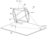
第1および第2の撮像の向き(220,230)におけるX線源202の3D位置が特定されると、様々な技術を用いて撮像された物体の3Dモデルを作成することができる。一実施形態では、第1の撮像の向き220と、第2の撮像の向き230との間の、撮像軸I周りの角変位量が既知である。この実施形態に対応する例は、図12A〜図12Gに図示される。図12Aは、2つの向き(1220,1230)において撮像される物体1201を図示する。2つの相対的向き(1220,1230)における画像は、撮像される物体1201を撮像軸Iの周りに角変位αだけ回転させることにより、または、X線源および撮像装置を撮像軸Iの周りに角変位αだけ回転させることにより、準備することができる。撮像軸Iは、第1の向き1220のX線撮像装置(図示せず)の平面と、第2の向き1230のX線撮像装置の平面とに平行であることが好ましいが、これは必須ではない。2つの向きにおいてこれらの画像を作成することにより、結果として、向き1220,1230にそれぞれ対応する2つのレントゲン画像(1202,1204)が得られる。また、図12Aには、レントゲン画像(1202,1204)それぞれに対するX線源1212の相対的位置が示されている。これらのX線源1212の3D位置は、上述のようにレントゲン画像(1202,1204)上に参照マーカーにより作成される影に基づいて決定してもよいし、当該技術分野で既知の任意の他の技術(たとえば撮像装置104に対するX線源1212の位置を物理的に測定する等)により決定してもよい。
Once the 3D position of the
物体1201の3Dモデルの作成における別のステップは、レントゲン画像における撮像された物体1201のアウトラインを決定することである。このコンセプトは図12Bに図示されており、図12Bでは、第1のレントゲン画像1202における撮像された物体のアウトラインがアウトライン1213として特定されている。同様に、第2のレントゲン画像1204における撮像された物体のアウトラインがアウトライン1215として特定されている。レントゲン画像はコンピュータシステムに記憶されるデジタル画像であるが、この処理は画像処理ソフトウェアを用いることにより自動的に実行可能である。別の実施形態によれば、この処理は、レントゲン画像における撮像された物体のアウトラインを、マウス、スタイラスまたは他の任意のトレース装置でトレースすることにより、手作業で実行可能である。撮像された物体のアウトラインと、X線源1212の3D位置とを決定した後に、撮像された物体のアウトラインの投影を作成することができる。第1の向き120における物体アウトライン1213の投影は、図12Bにおいて、第1のレントゲン画像1202におけるアウトライン1213から第1の向き1220におけるX線源1212の3D位置まで通過する投影線308によって示される。同様に、第2の向き1230における物体アウトライン1215の投影は、図12Bにおいて、第2のレントゲン画像1204におけるアウトライン1215から第2の向き1230におけるX線源1212の3D位置まで通過する投影線1216によって示される。
Another step in creating a 3D model of the
第1および第2のレントゲン画像(1220,1230)それぞれについて撮像された物体の投影が作成されると、それらの投影が互いにどのように交差するかを、向き(1220,1230)の互いに対する相対的位置を用いて決定することができる。これは様々な方法で行うことができる。一実施形態では、各3D投影を、図12A〜図12Eに図示されるx,y,z参照フレーム1250に対応する単一の3D参照フレーム内に組み合わせてもよい。x,y,z参照フレーム1250の原点は、撮像軸Iに沿って、第1の向き1220におけるX線源1212からのX線が撮像軸と垂直に交差し、第2の向き1230におけるX線源1212からのX線が撮像軸と垂直に交差する点1251に配置されてもよい。上述のように、この参照フレーム1250において、角度αは、x軸または撮像軸Iの周りの、2つの向き(1220,1230)の間の角変位量に対応する。この角度αは様々な方法で決定することができる。X線源1212および撮像装置が静止しており物体が回転する実施形態では、図2Aおよび図2Bに示すように、角度αはx軸または撮像軸Iの周りの物体の回転量に対応する。物体が静止しているがX線源1212および撮像装置が物体の周りに回転する代替的実施形態では、図2Aおよび図2Bに示すように、角度αは、撮像軸Iの周りのX線源1212および撮像装置の回転量に対応する。X線源1212および撮像装置を撮像される物体1201の周りに回転する時には、X線源1212の位置が撮像装置の位置に対して固定されていることが好ましい可能性があるが、これは必須ではない。さらに、レントゲン画像(1202,1204)は、互いに実質的に直交する向き(1220,1230)において取得されることが好ましい可能性があるが、これは必須ではない。上記の角変位αとアウトラインの投影とを用いて、レントゲン画像(1202,1204)の相対的位置と、それらの対応する投影とを互いに位置合わせすることができる。
When projections of the imaged objects are created for each of the first and second X-ray images (1220, 1230), how the projections intersect each other is relative to each other in orientation (1220, 1230). Can be determined using the target position. This can be done in various ways. In one embodiment, each 3D projection may be combined in a single 3D reference frame corresponding to the x, y,
角度βおよびγは、それぞれ、z軸およびy軸周りの、第2のレントゲン画像1204に対する第1のレントゲン画像1202の角変位に対応する。上述のように、実施形態によっては、第1および第2の相対的向き1220および1230が互いに実質的に直交しており、それらの実施形態では角度βおよびγは実質的に0であってもよい。第1および第2の相対的向き1220および1230が互いに実質的に直交していない実施形態では、第1および第2のレントゲン画像(1202,1204)はさらに、様々な手法(本開示に記載される反復的手法を含む)を用いて、角度βおよびγで位置合わせすることができる。レントゲン画像(1202,1204)を角度βおよびγで位置合わせすることは任意選択的であるが、位置合わせすることによってより正確な物体1201の3Dモデルが可能になる可能性があるということが理解される。
The angles β and γ correspond to the angular displacement of the
図12Cは、撮像された物体1201のレントゲン画像(1202,1204)と、撮像された物体1201の3D物体投影とが、複数の平面(平面1231,1232,1234を含む)と交差し得るということを図示する。これらの平面は、それぞれ、第1の向き1220におけるX線源1212の位置に対応する3D参照フレームにおける第1の3D位置と、第2の向き1230におけるX線源1212の位置に対応する3D参照フレームにおける第2の3D位置とを通過する。また、図12Cは、3D参照フレームにおいて第1および第2の3D位置を通過する傾斜軸1236を図示する。平面1231,1232,1234は、傾斜軸1236の周りにそれぞれ異なる傾斜を有し、第1および第2のレントゲン画像(1202,1204)において撮像された物体1201のアウトラインと交差する。平面1231と、第1および第2のレントゲン画像(1202,1204)における画像アウトラインとの交点の位置は、点318でマークされている。平面1232と、第1および第2のレントゲン画像(1202,1204)における画像アウトラインとの交点の位置は、点1240でマークされている。平面1234と、第1および第2のレントゲン画像(1202,1204)における画像アウトラインとの交点の位置は、点1244でマークされている。
FIG. 12C shows that the X-ray image (1202, 1204) of the imaged
図12Dでは、交点1238,1240,1242は、それぞれ、対応する向き(120,150)で3D参照フレーム1250においてX線源1212の位置に接続されている。したがって、レントゲン画像1202における交点1238,1240,1242は、直線324によって、3D参照フレーム1250における第1の3D位置に接続されており、これは第1の向き1220におけるX線源1212の位置に対応する。同様に、レントゲン画像1204における交点1238,1240,1242は、直線1256によって、3D参照フレーム1250における第2の3D位置に接続されており、これは第2の向き1230におけるX線源1212の位置に対応する。さらに、第1および第2のレントゲン画像(1202,1204)における点の組1238と交差する4本の直線は、また、3D参照フレーム1250における多角形1258を形成するよう互いに交差する。同様にして、第1および第2のレントゲン画像(1202,1204)における点の組1240と交差する4本の直線は、また、3D参照フレーム1250における多角形1258を形成するよう互いに交差する。さらに、第1および第2のレントゲン画像(1202,1204)における点の組1242と交差する4本の直線は、また、3D参照フレーム1250における多角形1258を形成するよう互いに交差する。
In FIG. 12D, the intersection points 1238, 1240, and 1242 are connected to the position of the
図12Eにおいて、多角形1258を定義する処理は、十分な解に到達するか、または撮像された物体1201との交点がそれ以上発見されなくなるまで、傾斜軸1236と位置合わせされた1つ以上の平面について繰り返されてもよい。これらの多角形1258は、それぞれ、参照フレーム1250における、第1および第2の向き(1202,1204)における3D物体投影の間の交差部分に対応する。
In FIG. 12E, the process of defining the
3D投影の交差部分に対応する多角形1258の系列を作成した後に、各多角形1258を、図12Fに図示される撮像された物体1201の断面形状に対応する閉曲線(たとえば楕円)1290へと変換してもよい。多角形1258の系列を閉曲線1290に変換する前に、撮像された物体1201の概略的な形状および向きが既知であることが好ましいが、これは必須ではない。たとえば、撮像された物体(骨等)が、概して楕円の断面形状を有している場合には、各多角形1258は、その多角形内に配置される閉曲線1290(楕円等)によって置き換えることが可能である。一方、撮像された物体が非対称な形状を有している場合には、物体の正確な3Dモデルを作成するために、撮像された物体についての他の情報(たとえば、形状、断面、向き、等)を用いることができる。各多角形1258が対応する形状(たとえば閉曲線または楕円)1290によって置き換えられると、これらの形状を接続する表面を準備することができる。この表面は、図12Gに図示するように、撮像された物体の正確な3Dモデル1292を表す場合がある。いくつかの実施形態では、3Dモデル332の精度は、画像ライブラリに格納された既知の形状に従ってモデル1292を修正することによって改善することができる。
After creating a series of
上述のように、第1および第2の相対的な向き1220および1230が実質的に直交しない場合には、角度βおよびγは、本開示の原理に従って反復的手法を用いて決定されてもよい。一例示的実施形態では、レントゲン画像(1202,1204)は、まずレントゲン画像(1202,1204)を既知のαで位置合わせし、その後、レントゲン画像(1202,1204)を様々な角度βおよびγで位置合わせすることによって撮像された物体1201の様々なテスト3Dモデルを作成し、最後に第1および第2のレントゲン画像1202および1204において撮像された物体1201のアウトラインに実質的にマッチする2D投影を作成する3Dモデルを特定することによって、角度βおよびγに向けられてもよい。物体1201のテストモデルは、精度をより良くするために、図12C〜図12Gに関連して上述された手法に従って作成されてもよい。しかしながら、当該技術分野で既知の任意の適切なモデル化技術に従って様々なモデルを生成してもよいということが理解される。
As described above, if the first and second
別の実施形態では、物体の3Dモデルは、2つの撮像の向き(1220,1230)の間の角変位αが既知でない時であっても、固定された参照フレームにおいて作成可能である。この実施形態に対応する例は、図13A〜図13Eに図示される。直前に述べた、角変位αが既知である処理と同様に、物体の2つのレントゲン画像が異なる複数の向きにおいて準備される。これらのレントゲン画像は、それぞれ、物体マーカーが取り付けられた物体1301の画像を含む。少なくとも1つの物体マーカー1342は、物体1301に直接的または間接的に取り付けられてもよく、物体マーカー1342の数は、それぞれが含む基準(fiducial)の数に応じて変化してもよい。一例示的実施形態では、少なくとも1つの物体マーカー1342に、全部で少なくとも3つの基準が含まれる。この少なくとも3つの基準は、1つの物体マーカー1342に封入されてもよく(enclosed)、または複数の物体マーカー1342(たとえば2つまたは3つの物体マーカー1342等)にわたって分散してもよい。別の例示的実施形態では、少なくとも1つの物体マーカー1342に、全部で4つ以上の基準が含まれる。この4つ以上の基準は、1つのマーカー1342に封入されてもよく(enclosed)、または、基準の具体的な数に応じて、複数(たとえば2つ、3つ、4つ、またはそれ以上)の物体マーカー1342にわたって分散してもよい。
In another embodiment, a 3D model of the object can be created in a fixed reference frame even when the angular displacement α between the two imaging orientations (1220, 1230) is not known. An example corresponding to this embodiment is illustrated in FIGS. 13A-13E. Similar to the process just described, where the angular displacement α is known, two X-ray images of the object are prepared in different orientations. Each of these X-ray images includes an image of an
代表的な物体マーカー1342が取り付けられた物体1301の例が図13Aに図示される。図13Aでは、撮像された物体1301は、それぞれに取り付けられる4つの物体マーカー1342を含み、これらの物体マーカー1342はそれぞれ基準1344を含む。固定された参照フレームにおいて物体1301のモデルを作成するために物体マーカー1342を用いる第1の手法では、少なくとも3つの基準1344が直接的または間接的に少なくとも1つの撮像された物体1301に取り付けられていれば、物体マーカー1342の数および種類は異なってもよい。たとえば、一実施形態では、1つの物体マーカー1342が3つの基準1344を備えてもよい。別の例示的実施形態では、それぞれ2つの基準1344を備えた物体マーカー1342を2つ用いてもよい。さらに別の例示的実施形態では、基準1344を1つずつ備えた物体マーカー1342を3つ用いてもよい。いくつかの実施形態では3つの基準1344を用いてもよいが、以下に論じる理由から、4つ以上の基準1344を用いる実施形態がより望ましいということが理解される。さらに、固定された参照フレームにおいて物体1301のモデルを作成するために物体マーカー1342を用いる第1の手法によれば、基準1344の互いに対する位置は事前に決定されているということが理解される。一例示的実施形態では、基準1344間の線分の長さおよび向きを決定するために、測定値を取得してもよい。別の実施形態では、基準1344の互いに対する位置を事前に決定できるように、物体マーカー1342を事前に決定された向きに配置してもよい。この場合、基準1344の間の線分は数学的に決定可能である。
An example of an
図13Aに図示する実施形態では、物体マーカー1342の各画像が、それぞれ対応するレントゲン画像1302および1304に示されている。2つのレントゲン画像を受信する際に、X線撮像装置に対するX線源1312の3D位置が、本開示に開示される原理に従って、撮像の向き(1320,1330)のそれぞれについて決定されてもよい。とくに、このような決定は、上記の各実施形態に関連して記載されたものと同一の方法において、参照マーカーおよび基準の使用に基づいてもよい。同様に、第1および第2のレントゲン画像(1302,1304)における、撮像された物体1301のアウトラインと、基準1344の影点1306とは、直前の実施形態において記載されたものと同一の技術を用いて特定されてもよい。ここで、撮像された物体1301の3Dモデルを準備するために、物体マーカー1342および基準1344を用いて、異なるステップを利用してもよい。
In the embodiment illustrated in FIG. 13A, each image of the
一般的に、固定された参照フレームにおける物体1301のモデルを作成するために物体マーカー1342を用いる第1の手法は、図13Bに示すように、レントゲン画像(1302,1304)における影点1306と、それらがそれぞれ対応する撮像の向き(1320,1330)におけるX線源1312の位置とを接続する投影線1340を構成することを含む。各レントゲン画像(1302,1304)に対する基準1344の相対的な3D位置は、投影線410の向きと、基準1344間の事前に決定された線分とに基づいて数学的に決定してもよい。また、2つの撮像の向き220,230間の角変位αは、基準1344の3D位置を固定された参照フレームにおいて位置合わせすることによって決定してもよい。変位角度αが特定されると、撮像された物体の3Dモデルを作成する処理は、図12C〜図12Gに関連して記載したものと同一の方法で進行してもよい。
In general, a first technique that uses an
また、各レントゲン画像(1302,1304)に対する基準1344の3D位置の決定は、様々な数学的手法に従って達成可能であるということが理解される。一例示的数学的手法は、図13Cを参照して探索される。上述のように、マーカー(図示せず)は、3つの基準1344の互いに対する位置が事前に決定されたものとなるように、物体(図示せず)に固定されてもよい。図13Cに例示する実施形態では、レントゲン画像304における基準1344の影点1306を用いて、投影線1340(これらは幾何学的に協働して三角錐(three-sided pyramid)を形成してもよい)を構成してもよい。さらに、対応する基準1344の互いに対する位置は事前に決定されているので、各基準1344の3D位置を接続することによって形成される三角形1308の諸寸法もまた数学的に決定可能である。この場合、図13Cに示すように、以下の幾何学的要素が確立可能である:光源1312の座標(L)、影点406の座標(K,M,N)、三角形1308の辺(a,b,c)の長さ。図13Cの例示的手法は、三角形1308の3D位置および向きを決定するために、三角形1308の諸寸法と錐の外側輪郭とがマッチする位置に到達するまで、三角形1308を錐内で回転させかつ「移動」させることを含んでもよい。既知の三角測量および三角法の技術に基づき、三角形1308の位置は、次の方程式の系の解に対応するものであってもよい:
It is also understood that the determination of the 3D position of the
ここで、角度KLM,MLN,KLNはそれぞれα,β,γに対応し、x,y,zは、光源1312と基準1344との距離に対応する。この方程式の系は、数学的には8つの異なる解を持つが、それらの一部は複素数および負の数を含む可能性があり、したがって除外されてもよい。この場合、基準1344の位置を正しく反映し得る解が2つ残る可能性がある。しかしながら、残った2つの解のうちいずれが正しいかを数学的に決定するのは困難である。一実施形態では、双方の解に基づく画像物体の3Dモデルが人間に提示され、その人間が、撮像された物体の向きにマッチするモデルを視覚的に決定して選択してもよい。整形外科用途では、マッチするモデルを選択する人間は内科医であってもよい。
Here, the angles KLM, MLN, and KLN correspond to α, β, and γ, respectively, and x, y, and z correspond to the distance between the
モデル化処理をより速めるために、上述のように正しいモデルを選択する人間の関与を、図13Dおよび図13Eに関連して開示される手法に従って低減または排除してもよい。一般的に、上述の数学的モデルは、追加の基準の考慮を含むよう変更されてもよい。例示される手法によれば、追加の基準1344が1つ用いられて、3つでなく4つの基準1344が用いられ、結果として、3つの影点1306からなる組が4通りあることに基づいて4つの異なる三角錐が構成される。三角錐のそれぞれについていくつかの解が利用可能な場合がある。一実施形態では、異なる複数の解が互いに比較され、当該技術分野で既知の数学的基準に従って最終的な解が選択されてもよい。たとえば、他の解からの偏差(deviation)が最も小さい解を、レントゲン画像1304に対する基準1344の3D位置を決定するために選択してもよい。別の例では、基準1344の3D位置を決定するために、すべての解の平均値を選択してもよい。
To speed up the modeling process, human involvement in selecting the correct model as described above may be reduced or eliminated according to the techniques disclosed in connection with FIGS. 13D and 13E. In general, the mathematical model described above may be modified to include consideration of additional criteria. According to the illustrated technique, one
上述の各手法は、他のレントゲン画像1302に対する各基準1344の3D位置を決定するために繰り返されてもよい。そうすることによって、基準1344の3D位置を、2つの異なる座標系に対し、上述の手法に従って決定することができる。さらに、各基準を2つの座標系において位置合わせすることによって、図13Bに図示されるように、第1および第2のレントゲン画像の平行移動および回転の向き(x,y,z,α,β,γ)を、単一の固定された参照フレームにおいて決定することができる。いくつかの実施形態では、固定された参照フレームにおいて基準1344の3D位置を決定することによって、また、物体に対する、3D空間における基準1344の事前に決定された相対的な向きが与えられると、固定された参照フレームにおいて物体の3D位置を決定することができる。
Each of the above approaches may be repeated to determine the 3D position of each
上述の各例示的手法は、第2のレントゲン画像1304に対する第1のレントゲン画像1302の平行移動および回転の向き(x,y,z,α,β,γ)に対応する効率的かつ正確な方法を提供するために、3つまたは4つの基準1344を用いて実施してもよいが、本開示の原理に従う他の手法では、これら以外の数の基準1344を用いてもよいということが理解される。正確さおよび/または精密さをより高くできるようにするために、5つまたはそれ以上の基準を用いてもよい。たとえば、図13Aに示す実施形態では、8つの基準を用いてもよい。そのような場合には、3つの基準からなる組の組み合わせが56個存在してもよい。各組み合わせに対する少なくとも2つの可能な解によって、基準1344の位置について少なくとも112個の異なる可能な解が存在し得る。最終的な解は、基準1344の可能な位置すべての数学的分析に基づく、以下の例示的アルゴリズムに従って選択されてもよい:
Each exemplary approach described above is an efficient and accurate method that corresponds to the translation and rotation orientations (x, y, z, α, β, γ) of the
1)上述のようにして取得された可能な解すべてに基づき、各基準1344の潜在的3D位置をすべて決定する。
2)各基準1344の平均3D位置を決定する。
3)ステップ2で決定された平均3D位置それぞれからの、各基準1344の潜在的3D位置すべての偏差を決定する。
4)ステップ2で決定された平均3D位置それぞれから最も大きくずれている3D位置に対応する、最も尤度の低い3D位置を特定する。
5)最も尤度の低い3D位置を導いた解を排除する。
6)各基準1344の、残る潜在的3D位置のそれぞれの、対応する平均3D位置からの偏差が、閾値(たとえば2mm、5mm、10mm、等)より小さくなるまで、ステップ1 5を繰り返す。
7)各基準1344の3D位置を、各基準1344の、残る潜在的3D位置のそれぞれの平均として近似する。
1) Determine all potential 3D positions for each
2) Determine the average 3D position of each
3) Determine the deviation of all potential 3D positions of each
4) Specify the 3D position with the lowest likelihood corresponding to the 3D position that is the largest deviation from each of the average 3D positions determined in step 2.
5) Eliminate the solution that led to the least likelihood 3D position.
6) Repeat step 15 until the deviation of each of the remaining potential 3D positions of each
7) Approximate the 3D position of each
上記のアルゴリズムにより、基準1344の位置について正確な近似が可能になるということ、また、これは本明細書で論じた原理および当該技術分野で既知の任意の数学的技術に従って修正してもよいということが理解される。たとえば、一例示的実施形態では、このアルゴリズムは、各基準1344の潜在的位置間の分散を決定することを含み、平均および分散の双方から偏差に基づいて潜在的解を排除するよう、さらに修正されてもよい。
The above algorithm allows an accurate approximation of the position of the
[実用的考慮]
整形外科装置が物体とともにレントゲン画像に撮像された後、手作業で、または適切なグラフィックソフトウェアを用いて、整形外科装置のアウトラインを決定してもよい。たとえば、内科医が手作業で整形外科装置のアウトラインを取り、そのような情報をコンピュータに入力してもよい。別の実施形態では、整形外科装置のアウトラインはパターン認識ソフトウェアによって自動的に生成されてもよい。その場合、整形外科装置のアウトラインは、本開示に従って、物体の3Dモデルを決定するために用いられてもよい。
[Practical considerations]
After the orthopedic device has been imaged with the object into an X-ray image, the outline of the orthopedic device may be determined manually or using appropriate graphic software. For example, a physician may manually outline an orthopedic device and enter such information into a computer. In another embodiment, the orthopedic device outline may be automatically generated by pattern recognition software. In that case, the outline of the orthopedic device may be used to determine a 3D model of the object in accordance with the present disclosure.
いくつかの実施形態では、視認可能な影がデジタルのレントゲン画像上で2つ以上の画素にわたる可能性があるということが理解される。したがって、視認可能な影の正確な位置は、近似モデルを用いて近似されてもよい。図7は、一例示的近似モデル700の手法を図示するフローチャートである。近似モデル700は、複数の被制御画素領域(各被制御画素領域は複数の画素を含む)を定義するためのステップ702を含む。各被制御画素領域の複数の画素は、それぞれ、視認可能な影のそれぞれが配置される可能性が最も高い各位置に対応してもよい。たとえば、ある定義された被制御画素領域は、ある視認可能な影の周辺に3×3グリッドの9つの画素を含んでもよい。別の例では、ある定義された被制御画素領域は、ある視認可能な影の周辺に4×4グリッドの16個の画素を含んでもよい。例示的モデル700は、画素の様々な組(画素の各組は、それぞれ、定義された被制御画素領域からのピクセルを1つ含む)に基づいて、可能な影位置の複数の組み合わせを任意に割り当てるステップ704を含んでもよい。例示的モデル700は、割り当てられた影位置の組み合わせのそれぞれについて、望ましい参照点の位置を決定するステップ706を含んでもよい。たとえば、望ましい参照点は、リングの中心であってもよい。一実施形態では、望ましい参照点に対応する位置を決定するために、影位置の組み合わせがすべて割り当てられ、用いられる。別の実施形態では、望ましい参照点に対応する位置を決定するために、影位置の組み合わせのうち選択された組み合わせのみが割り当てられ、用いられる。例示的モデル700は、さらに、リングの中心の近似された位置を決定するために客観的判定基準を用いて望ましい参照点の第1および第2の位置を処理するステップ708を含んでも良い。例示的実施形態では、ステップ708のこの客観的判定基準は、当該技術分野において既知の、1つ以上の数学測定(平均、中央値、分散、標準偏差またはこれらの任意の組み合わせ、等)を含んでもよい。例示的実施形態では、差が0.01mmより大きい位置はすべて除去してもよい。選択された領域の組み合わせのいずれもその精度を持たない場合には、リングの中心の位置決定において差を最も小さくする組み合わせを用いてもよい。
It will be appreciated that in some embodiments, a visible shadow may span more than one pixel on a digital X-ray image. Accordingly, the exact position of the visible shadow may be approximated using an approximate model. FIG. 7 is a flowchart illustrating an exemplary
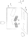
図8は、合成3D座標系850において固定具(fixture)のモデルを示す概略図である。図2A〜図2Bに関連して上述したように、2つのレントゲン画像に基づいて第1および第2の3D座標系が独立に作成され、それぞれ第1および第2の平面801および802を含んでいる。この第1および第2の3D座標系が組み合わされて、合成3D座標系850が作成される。第1および第2の平面801および802は、第1および第2の3D座標系における第1および第2の参照点の座標が一致するような角度に位置合わせされている。
FIG. 8 is a schematic diagram illustrating a fixture model in the composite 3D coordinate
図9は、固定具900の第1リング901に結合された第1の物体セグメント910と、固定具900の第2リング902に結合された第2の物体セグメント920とのモデルである。このモデルは、上述の方法を用いて生成された合成3D座標系850に基づいている。いくつかの実施形態では、図8のモデルにより、第2のセグメント920の向きに対する第1の骨セグメント910の向きを決定することができる。とくに、このモデルにより、第2リング902に対する第1リング901の様々な向きに基づいて、第1および第2の骨セグメント910および920の相対的な向きを数学的に決定することができる。
FIG. 9 is a model of a
本開示は、互いに実質的に直交する撮像の向き、または直交しない向きを用いることを説明してきた。これら2通りの実施形態からの選択は、様々な要素(器具の制限、および、特定の向きを撮像する関心またはその欠如を含む)に依存し得る。さらに、本開示の範囲と整合して、3つ以上の向きを利用してもよい。3つ以上の撮像の向きを用いることにより、フレームおよび組織の3Dモデルの精度を向上することができる。 The present disclosure has described using imaging orientations that are substantially orthogonal to each other, or non-orthogonal orientations. The choice from these two embodiments may depend on various factors, including instrument limitations and interest or lack of interest in imaging a particular orientation. Further, more than two orientations may be utilized consistent with the scope of this disclosure. By using more than two imaging orientations, the accuracy of the 3D model of the frame and tissue can be improved.
フレームおよび組織セグメントの3Dモデルが作成されると、内科医または外科医は、より容易に、破損の性質と、望ましい結果を達成するために組織セグメントに作用させるべき固定、圧縮または伸延(または他の力)の程度とを理解することができる。ヘキサポッドリング固定器の3Dモデルは、望ましい固定、圧縮または伸延の命令が自動的に実行されるように、自動化されたフレーム制御装置に結合することもできると考えられる。 Once the 3D model of the frame and tissue segment has been created, the physician or surgeon can more easily fix, compress or distract (or other) the nature of the failure and the tissue segment to act on to achieve the desired result. Understand the degree of power). It is contemplated that the 3D model of the hexapod ring fixator can also be coupled to an automated frame controller so that the desired locking, compression or distraction instructions are automatically executed.
上述のように、物体の3Dモデルは物体のレントゲン画像から生成されてもよい。図10は、本開示の原理に従って、撮像された物体(図示せず)の3Dモデルをデジタルに生成するよう動作可能なシステム1000の概略図である。システム1000は、撮像された物体のレントゲン画像を受信するよう動作可能なコンピュータワークステーション1002を含んでもよく、コンピュータワークステーション1002は、様々な補助装置と通信する1つ以上のマイクロプロセッサ/コントローラを含んでもよい。一実施形態では、システム1000は、コンピュータワークステーション1002と通信するX線撮像装置1004を含んでもよく、X線撮像装置1004は、X線源1006から出て撮像される物体を通過するX線を受信するよう動作可能であってもよい。X線撮像装置1004は、レントゲン画像を直接的に生成するよう動作可能であってもよいし、画像データをコンピュータワークステーション1002に送信するよう動作可能であってもよい(その場合にはコンピュータワークステーション1002がX線画像を生成する)。別の実施形態では、システム1000は、ワークステーション1002と通信するスキャナ1008を含んでもよく、スキャナ1008は、X線フィルムをデジタル化されたレントゲン画像へとスキャンするよう動作可能であってもよい。いくつかの実施形態では、システム1000はさらに、ワークステーション1002と通信するディスプレイ1010を含んでもよく、ディスプレイ1010は、LCDディスプレイであってもよく、CRTディスプレイであってもよく、当該技術分野において既知の他の任意の表示装置であってもよい。ワークステーション1002は、デジタル化されたレントゲン画像をユーザに対してディスプレイ1010上に表示するよう構成されてもよく、ユーザは、本開示におけるような、表示されたレントゲン画像に関連する様々なデータ(マーカーまたはストラットの位置、マーカーまたはストラットの互いに対する事前に決定された位置、等)を入力してもよい。一例示的実施形態では、システム1000は、ワークステーション1002と通信する1つ以上の入力装置1012(マウス、ライトペンおよび/またはキーボード等)を含み、ユーザはこの入力装置1012を用いてデータを入力してもよい。ワークステーション1002のマイクロプロセッサまたはコントローラは、ユーザ入力データおよび画像データに基づき、本開示に従って、撮像された物体の3Dモデルを生成してもよい。いくつかの実施形態では、システム1000はさらに、ユーザに様々なモデルデータ、計算結果、画像またはグラフィックスを提供するよう動作可能な出力装置1014(プリンター等)を含んでもよい。システム1000はさらに、様々なモデルデータ、計算結果、画像またはグラフィックスを、後に使用するために格納するための記憶モジュール1016を含んでもよい。
As described above, a 3D model of an object may be generated from an X-ray image of the object. FIG. 10 is a schematic diagram of a
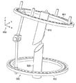
図11は、図10に例示されるシステムの応用の概略図である。本実施形態は、本開示の原理に従って、撮像された物体の3Dモデルをデジタル的に生成する。患者がテーブル1101に座るかまたは横たわっていてもよい。他の実施形態では、患者はテーブル1101でなく椅子に座っていてもよい。テーブル1101の表面は、撮像装置と同一の材料から構成されてもよい。代替的に、撮像装置は、テーブル1101の表面の上、患者の下に配置されてもよい。X線およびレントゲン画像によって検査されるべき領域(本実施形態では脚)は、整形外科固定器1109で取り囲まれている。整形外科固定器1109で取り囲まれた脚は、本開示の原理に従って、X線装置1102によってX線照射される。整形外科固定器1109で取り囲まれた脚は、x,y,z方向において回転可能なX線装置1102によって、異なる複数の向きからX線照射されてもよい。
FIG. 11 is a schematic diagram of application of the system illustrated in FIG. This embodiment digitally generates a 3D model of the imaged object in accordance with the principles of the present disclosure. A patient may sit or lie on the table 1101. In other embodiments, the patient may be sitting in a chair instead of the table 1101. The surface of the table 1101 may be made of the same material as the imaging device. Alternatively, the imaging device may be placed on the surface of the table 1101 and below the patient. The area to be examined by X-ray and X-ray images (in this embodiment, the leg) is surrounded by an
X線照射されたデータは、インターネットまたは他の適切なネットワークを介して、ケーブル(図示せず)を通じてまたは無線で、ユーザのローカルマシン1107に送信される。ユーザのローカルマシン1107は、本実施形態では通常のデスクトップコンピュータであるが、図10のコンピュータワークステーション1002として例示されるような任意の計算装置であってもよい。ユーザのローカルマシン1107は、X線データを受信し、処理し、記憶するためのプロセッサおよびメモリを備えてもよい。ユーザのローカルマシン1107は、X線データを画像として表示するディスプレイ1103に接続されてもよい。ユーザのローカルマシン1107は、マウス1104、キーボード(図示せず)、およびスキャナ/プリンタ1108に接続されてもよい。スキャナ/プリンタ1108は、X線画像をスキャンするか、または送信されたX線データを印刷するよう動作可能である。X線データは、また、CD、ユニバーサルシリアルバス(USB)ドライブ1105または任意の他の記憶装置(フロッピー(登録商標)ディスク等)によってユーザのローカルマシン1107に供給されてもよい。
X-rayed data is transmitted to the user's
患者の脚および固定器の3D位置は、開示された方法に従って決定される。その後、ユーザは、送信されたX線データを処理して、整形外科固定器1109に与えられなければならない必要な調整を決定する。ユーザは、これらの決定に基づき、ユーザのローカルマシン1107に接続されたプログラマブルレンチ1106を用いて、接続点を締めるまたは緩めることにより、自動的に整形外科固定器1109を調整してもよい。代替的に、ユーザ(最も可能性が高い者は内科医または医療スタッフメンバー)は、送信されたX線データに基づき、整形外科固定器1109を手作業で調整してもよい。
The 3D position of the patient's leg and fixator is determined according to the disclosed method. The user then processes the transmitted x-ray data to determine the necessary adjustments that must be provided to the
本明細書に記載される特定の実施形態は、発明の限定ではなく、例示という方法によって示されているということが理解される。本発明の主要な特徴は、本発明の範囲から逸脱することなく、様々な実施形態において採用可能である。当業者は、本明細書に記載された特定の手順のいくつかの均等物を、せいぜい日常的な実験法を用いることにより、認識し、または把握することができる。そのような均等物は、本発明の範囲内であると考えられ、特許請求の範囲によってカバーされる。 It is understood that the specific embodiments described herein are shown by way of illustration and not limitation of the invention. The principal features of this invention can be employed in various embodiments without departing from the scope of the invention. Those skilled in the art will recognize, or be able to ascertain using no more than routine experimentation, some equivalents of the specific procedures described herein. Such equivalents are considered to be within the scope of this invention and are covered by the claims.
本明細書において言及したすべての刊行物および特許出願は、本発明に関連する技術分野における当業者の水準を示す。すべての刊行物および特許出願は、各刊行物または各特許出願が参照により組み込まれるものとして個別にかつ独立して示された場合と同程度に、参照により本明細書に組み込まれる。 All publications and patent applications mentioned in the specification are indicative of the level of those skilled in the art to which this invention pertains. All publications and patent applications are incorporated herein by reference to the same extent as if each publication or patent application was individually and independently presented as being incorporated by reference.
本発明の方法およびシステムは、好適な実施形態に関して記述してきたが、これらの方法およびシステムに対して、また、本明細書に記載される方法の各ステップまたはステップの系列において、本発明のコンセプト、精神および範囲から逸脱することなく、変更を加えることができるということが当業者には明白である。当業者に明白な、すべてのそのような同様な置き換えおよび修正は、添付の特許請求の範囲によって定義される本発明の、精神、範囲およびコンセプトの範囲内にあると考えられる。 Although the method and system of the present invention have been described with reference to preferred embodiments, the inventive concept for these methods and systems and at each step or series of steps of the methods described herein. It will be apparent to those skilled in the art that modifications can be made without departing from the spirit and scope. All such similar substitutes and modifications apparent to those skilled in the art are deemed to be within the spirit, scope and concept of the invention as defined by the appended claims.
Claims (8)
前記身体部分は、整形外科固定器に結合され、
前記整形外科固定器は、前記整形外科固定器に沿って、事前に決定された距離において、複数のマーカーを備え、
前記方法は、
第1の向きにおいて、X線源とX線撮像装置との間に配置された前記身体部分および前記整形外科固定器の、第1のレントゲン画像を受信することであって、前記第1のレントゲン画像は、
‐前記身体部分と、
‐前記整形外科固定器と、
‐前記複数のマーカーと
の画像を含む、第1のレントゲン画像を受信することと、
第2の向きにおいて、前記X線源と前記X線撮像装置との間に配置された前記身体部分および前記整形外科固定器の、第2のレントゲン画像を受信することであって、前記第2のレントゲン画像は、
‐前記身体部分と、
‐前記整形外科固定器と、
‐前記複数のマーカーと
の画像を含む、第2のレントゲン画像を受信することと、
前記第1のレントゲン画像上の前記複数のマーカーの投影の第1の組を決定することと、
前記複数のマーカー間の前記事前に決定された距離と、前記第1のレントゲン画像上の前記複数のマーカーの投影の前記第1の組とを用いて、前記第1の向きにおける前記X線撮像装置に対する、前記X線源の第1の3D位置と、前記整形外科固定器の第1の3D位置とを決定することと、
前記第2のレントゲン画像上の前記複数のマーカーの投影の第2の組を決定することと、
前記複数のマーカー間の前記事前に決定された距離と、前記第2のレントゲン画像上の前記複数のマーカーの投影の前記第2の組とを用いて、前記第2の向きにおける前記X線撮像装置に対する、前記X線源の第2の3D位置と、前記整形外科固定器の第2の3D位置とを決定することと、
前記第1および第2の向きにおける前記X線撮像装置に対する、前記複数のマーカーの前記各3D位置を用いて、3D参照フレームにおける前記第1および第2の3D整形外科固定器投影を位置合わせすることと、
前記第1および第2の3D整形外科固定器投影に基づいて、前記3D参照フレームにおける撮像された身体部分の3Dモデルを作成することと
を備え、
前記方法はさらに、
前記第1のレントゲン画像において、撮像された身体部分の、第1身体部分アウトラインを特定することと、
前記第2のレントゲン画像において、撮像された身体部分の、第2身体部分アウトラインを特定することと、
前記第1身体部分アウトラインから、前記X線源の前記第1の3D位置への、第1の3D身体部分投影を準備することと、
前記第2身体部分アウトラインから、前記X線源の前記第2の3D位置への、第2の3D身体部分投影を準備することと、
前記第1の身体部分投影および第2の身体部分投影に基づき、前記3D参照フレームにおいて前記撮像された身体部分の3Dモデルを作成することと、
前記3D参照フレームにおいて傾斜軸を特定することであって、前記傾斜軸は、
‐前記第1の向きにおける前記X線源の前記第1の位置に対応する、前記3D参照フレームにおける第1の3D位置と、
‐前記第2の向きにおける前記X線源の前記第2の位置に対応する、前記3D参照フレームにおける第2の3D位置と、
の間を通過する、傾斜軸を特定することと、
前記傾斜軸を通過し、前記3D参照フレームにおける前記撮像された身体部分の前記第1および第2の3D投影を通過する、1つ以上の交差平面を特定することと、
前記1つ以上の交差平面のそれぞれについて、次のステップa)〜c)を実行すること:
a)前記3D参照フレームにおいて、前記第1の3D身体部分投影および前記第2の3D身体部分投影の間の交点を1つ以上と、前記交差平面とを特定すること、
b)前記交差平面内で各前記交点を接続する1つ以上の多角形を準備すること、
c)前記1つ以上の多角形のそれぞれの内部に1つ以上の閉曲線を準備することであって、前記1つ以上の閉曲線は、前記交差平面における前記撮像された身体部分の断面図に対応する、1つ以上の閉曲線を準備すること、
と、
前記撮像された身体部分の3Dモデルを形成するために、前記3D参照フレームにおいて、前記閉曲線のそれぞれを接続する表面を準備することと
を備える、方法。 A method for creating a 3D model of a body part,
The body part is coupled to an orthopedic fixator;
The orthopedic fixator comprises a plurality of markers at a predetermined distance along the orthopedic fixator;
The method
Receiving a first X-ray image of the body part and the orthopedic fixator disposed between an X-ray source and an X-ray imaging device in a first orientation, the first X-ray The image
-The body part;
-The orthopedic fixator;
-Receiving a first X-ray image comprising an image with said plurality of markers;
Receiving, in a second orientation, a second X-ray image of the body part and the orthopedic fixator disposed between the X-ray source and the X-ray imaging device, the second X-ray image comprising: X-ray image of
-The body part;
-The orthopedic fixator;
-Receiving a second X-ray image comprising an image with said plurality of markers;
Determining a first set of projections of the plurality of markers on the first X-ray image;
The X-rays in the first orientation using the predetermined distance between the plurality of markers and the first set of projections of the plurality of markers on the first X-ray image. Determining a first 3D position of the x-ray source relative to an imaging device and a first 3D position of the orthopedic fixator;
Determining a second set of projections of the plurality of markers on the second X-ray image;
The X-ray in the second orientation using the predetermined distance between the plurality of markers and the second set of projections of the plurality of markers on the second X-ray image. Determining a second 3D position of the x-ray source relative to an imaging device and a second 3D position of the orthopedic fixator;
Align the first and second 3D orthopedic fixator projections in a 3D reference frame using the respective 3D positions of the plurality of markers relative to the x-ray imaging device in the first and second orientations. And
Creating a 3D model of the imaged body part in the 3D reference frame based on the first and second 3D orthopedic fixator projections ;
The method further comprises:
Identifying a first body part outline of the imaged body part in the first X-ray image;
Identifying a second body part outline of the imaged body part in the second X-ray image;
Providing a first 3D body part projection from the first body part outline to the first 3D position of the x-ray source;
Providing a second 3D body part projection from the second body part outline to the second 3D position of the x-ray source;
Creating a 3D model of the imaged body part in the 3D reference frame based on the first body part projection and the second body part projection;
Identifying a tilt axis in the 3D reference frame, wherein the tilt axis is
-A first 3D position in the 3D reference frame corresponding to the first position of the X-ray source in the first orientation;
-A second 3D position in the 3D reference frame corresponding to the second position of the X-ray source in the second orientation;
Identifying the tilt axis that passes between
Identifying one or more intersecting planes that pass through the tilt axis and pass through the first and second 3D projections of the imaged body part in the 3D reference frame;
Performing the following steps a) to c) for each of the one or more intersecting planes:
a) identifying in the 3D reference frame one or more intersections between the first 3D body part projection and the second 3D body part projection and the intersection plane;
b) providing one or more polygons connecting each intersection point in the intersection plane;
c) providing one or more closed curves within each of the one or more polygons, the one or more closed curves corresponding to a cross-sectional view of the imaged body part in the intersection plane; Preparing one or more closed curves;
When,
Providing a surface connecting each of the closed curves in the 3D reference frame to form a 3D model of the imaged body part;
A method comprising:
さらに、前記X線源の前記第1の3D位置および前記整形外科固定器の前記第1の3D位置は、次の関係により決定され、
さらに、前記X線源の前記第2の3D位置および前記整形外科固定器の前記第2の3D位置は、次の関係により決定され、
請求項1に記載の方法。 The plurality of markers includes five markers;
Furthermore, the first 3D position of the x-ray source and the first 3D position of the orthopedic fixator are determined by the following relationship:
Further, the second 3D position of the x-ray source and the second 3D position of the orthopedic fixator are determined by the following relationship:
The method of claim 1.
さらに、前記X線源の前記第1の3D位置および前記整形外科固定器の前記第1の3D位置は、次の関係により決定され、
さらに、前記X線源の前記第2の3D位置および前記整形外科固定器の前記第2の3D位置は、次の関係により決定され、
請求項1に記載の方法。 The plurality of markers includes four markers,
Furthermore, the first 3D position of the x-ray source and the first 3D position of the orthopedic fixator are determined by the following relationship:
Further, the second 3D position of the x-ray source and the second 3D position of the orthopedic fixator are determined by the following relationship:
The method of claim 1.
前記命令は、コンピュータに、以下の各ステップ:
第1の向きにおいて、X線源とX線撮像装置との間に配置された前記身体部分および前記整形外科固定器の、第1のレントゲン画像を受信することであって、前記第1のレントゲン画像は、
‐前記身体部分と、
‐前記整形外科固定器と、
‐前記複数のマーカーと
の画像を含む、第1のレントゲン画像を受信することと、
第2の向きにおいて、前記X線源と前記X線撮像装置との間に配置された前記身体部分および前記整形外科固定器の、第2のレントゲン画像を受信することであって、前記第2のレントゲン画像は、
‐前記身体部分と、
‐前記整形外科固定器と、
‐前記複数のマーカーと
の画像を含む、第2のレントゲン画像を受信することと、
前記第1のレントゲン画像上の前記複数のマーカーの投影の第1の組を決定することと、
前記複数のマーカー間の前記事前に決定された距離と、前記第1のレントゲン画像上の前記複数のマーカーの投影の前記第1の組とを用いて、前記第1の向きにおける前記X線撮像装置に対する、前記X線源の第1の3D位置と、前記整形外科固定器の第1の3D位置とを決定することと、
前記第2のレントゲン画像上の前記複数のマーカーの投影の第2の組を決定することと、
前記複数のマーカー間の前記事前に決定された距離と、前記第2のレントゲン画像上の前記複数のマーカーの投影の前記第2の組とを用いて、前記第2の向きにおける前記X線撮像装置に対する、前記X線源の第2の3D位置と、前記整形外科固定器の第2の3D位置とを決定することと、
前記第1および第2の向きにおける前記X線撮像装置に対する、前記複数のマーカーの前記各3D位置を用いて、3D参照フレームにおける前記第1および第2の3D整形外科固定器投影を位置合わせすることと、
前記第1および第2の3D整形外科固定器投影に基づいて、前記3D参照フレームにおける撮像された身体部分の3Dモデルを作成することと、
前記第1のレントゲン画像において、撮像された身体部分の、第1身体部分アウトラインを特定することと、
前記第2のレントゲン画像において、撮像された身体部分の、第2身体部分アウトラインを特定することと、
前記第1身体部分アウトラインから、前記X線源の前記第1の3D位置への、第1の3D身体部分投影を準備することと、
前記第2身体部分アウトラインから、前記X線源の前記第2の3D位置への、第2の3D身体部分投影を準備することと、
前記第1の身体部分投影および第2の身体部分投影に基づき、前記3D参照フレームにおいて前記撮像された身体部分の3Dモデルを作成することと、
前記3D参照フレームにおいて傾斜軸を特定することであって、前記傾斜軸は、
‐前記第1の向きにおける前記X線源の前記第1の位置に対応する、前記3D参照フレームにおける第1の3D位置と、
‐前記第2の向きにおける前記X線源の前記第2の位置に対応する、前記3D参照フレームにおける第2の3D位置と、
の間を通過する、傾斜軸を特定することと、
前記傾斜軸を通過し、前記3D参照フレームにおける前記撮像された身体部分の前記第1および第2の3D投影を通過する、1つ以上の交差平面を特定することと、
前記1つ以上の交差平面のそれぞれについて、次のステップa)〜c)を実行すること:
a)前記3D参照フレームにおいて、前記第1の3D身体部分投影および前記第2の3D身体部分投影の間の交点を1つ以上と、前記交差平面とを特定すること、
b)前記交差平面内で各前記交点を接続する1つ以上の多角形を準備すること、
c)前記1つ以上の多角形のそれぞれの内部に1つ以上の閉曲線を準備することであって、前記1つ以上の閉曲線は、前記交差平面における前記撮像された身体部分の断面図に対応する、1つ以上の閉曲線を準備すること、
と、
前記撮像された身体部分の3Dモデルを形成するために、前記3D参照フレームにおいて、前記閉曲線のそれぞれを接続する表面を準備することと
を実行させる、命令が符号化されたコンピュータメモリ装置。 A computer memory device encoded with instructions comprising:
The instructions give the computer the following steps:
Receiving a first X-ray image of the body part and the orthopedic fixator disposed between an X-ray source and an X-ray imaging device in a first orientation, the first X-ray The image
-The body part;
-The orthopedic fixator;
-Receiving a first X-ray image comprising an image with said plurality of markers;
Receiving, in a second orientation, a second X-ray image of the body part and the orthopedic fixator disposed between the X-ray source and the X-ray imaging device, the second X-ray image comprising: X-ray image of
-The body part;
-The orthopedic fixator;
-Receiving a second X-ray image comprising an image with said plurality of markers;
Determining a first set of projections of the plurality of markers on the first X-ray image;
The X-rays in the first orientation using the predetermined distance between the plurality of markers and the first set of projections of the plurality of markers on the first X-ray image. Determining a first 3D position of the x-ray source relative to an imaging device and a first 3D position of the orthopedic fixator;
Determining a second set of projections of the plurality of markers on the second X-ray image;
The X-ray in the second orientation using the predetermined distance between the plurality of markers and the second set of projections of the plurality of markers on the second X-ray image. Determining a second 3D position of the x-ray source relative to an imaging device and a second 3D position of the orthopedic fixator;
Align the first and second 3D orthopedic fixator projections in a 3D reference frame using the respective 3D positions of the plurality of markers relative to the x-ray imaging device in the first and second orientations. And
Creating a 3D model of the imaged body part in the 3D reference frame based on the first and second 3D orthopedic fixator projections ;
Identifying a first body part outline of the imaged body part in the first X-ray image;
Identifying a second body part outline of the imaged body part in the second X-ray image;
Providing a first 3D body part projection from the first body part outline to the first 3D position of the x-ray source;
Providing a second 3D body part projection from the second body part outline to the second 3D position of the x-ray source;
Creating a 3D model of the imaged body part in the 3D reference frame based on the first body part projection and the second body part projection;
Identifying a tilt axis in the 3D reference frame, wherein the tilt axis is
-A first 3D position in the 3D reference frame corresponding to the first position of the X-ray source in the first orientation;
-A second 3D position in the 3D reference frame corresponding to the second position of the X-ray source in the second orientation;
Identifying the tilt axis that passes between
Identifying one or more intersecting planes that pass through the tilt axis and pass through the first and second 3D projections of the imaged body part in the 3D reference frame;
Performing the following steps a) to c) for each of the one or more intersecting planes:
a) identifying in the 3D reference frame one or more intersections between the first 3D body part projection and the second 3D body part projection and the intersection plane;
b) providing one or more polygons connecting each intersection point in the intersection plane;
c) providing one or more closed curves within each of the one or more polygons, the one or more closed curves corresponding to a cross-sectional view of the imaged body part in the intersection plane; Preparing one or more closed curves;
When,
Computer-encoded instructions for causing a surface connecting each of the closed curves to be executed in the 3D reference frame to form a 3D model of the imaged body part apparatus.
前記コンピュータコードセグメントは、コンピュータに、以下の各ステップ:
第1の向きにおいて、X線源とX線撮像装置との間に配置された前記身体部分および物体の、第1のレントゲン画像を受信することであって、前記第1のレントゲン画像は、
‐前記身体部分と、
‐前記物体と、
‐前記複数のマーカーと
の画像を含む、第1のレントゲン画像を受信することと、
第2の向きにおいて、前記X線源と前記X線撮像装置との間に配置された前記身体部分および前記物体の、第2のレントゲン画像を受信することであって、前記第2のレントゲン画像は、
‐前記身体部分と、
‐前記物体と、
‐前記複数のマーカーと
の画像を含む、第2のレントゲン画像を受信することと、
前記第1のレントゲン画像上の前記複数のマーカーの投影の第1の組を決定することと、
前記複数のマーカー間の前記事前に決定された距離と、前記第1のレントゲン画像上の前記複数のマーカーの投影の前記第1の組とを用いて、前記第1の向きにおける前記X線撮像装置に対する、前記X線源の第1の3D位置と、前記物体の第1の3D位置とを決定することと、
前記第2のレントゲン画像上の前記複数のマーカーの投影の第2の組を決定することと、
前記複数のマーカー間の前記事前に決定された距離と、前記第2のレントゲン画像上の前記複数のマーカーの投影の前記第2の組とを用いて、前記第2の向きにおける前記X線撮像装置に対する、前記X線源の第2の3D位置と、前記物体の第2の3D位置とを決定することと、
前記第1および第2の向きにおける前記X線撮像装置に対する、前記複数のマーカーの前記各3D位置を用いて、3D参照フレームにおける前記第1および第2の3D物体投影を位置合わせすることと、
前記第1および第2の3D物体投影に基づいて、前記3D参照フレームにおける撮像された身体部分の3Dモデルを作成することと、
前記第1のレントゲン画像において、撮像された身体部分の、第1身体部分アウトラインを特定することと、
前記第2のレントゲン画像において、撮像された身体部分の、第2身体部分アウトラインを特定することと、
前記第1身体部分アウトラインから、前記X線源の前記第1の3D位置への、第1の3D身体部分投影を準備することと、
前記第2身体部分アウトラインから、前記X線源の前記第2の3D位置への、第2の3D身体部分投影を準備することと、
前記第1の身体部分投影および第2の身体部分投影に基づき、前記3D参照フレームにおいて前記撮像された身体部分の3Dモデルを作成することと、
前記3D参照フレームにおいて傾斜軸を特定することであって、前記傾斜軸は、
‐前記第1の向きにおける前記X線源の前記第1の位置に対応する、前記3D参照フレームにおける第1の3D位置と、
‐前記第2の向きにおける前記X線源の前記第2の位置に対応する、前記3D参照フレームにおける第2の3D位置と、
の間を通過する、傾斜軸を特定することと、
前記傾斜軸を通過し、前記3D参照フレームにおける前記撮像された身体部分の前記第1および第2の3D投影を通過する、1つ以上の交差平面を特定することと、
前記1つ以上の交差平面のそれぞれについて、次のステップa)〜c)を実行すること:
a)前記3D参照フレームにおいて、前記第1の3D身体部分投影および前記第2の3D身体部分投影の間の交点を1つ以上と、前記交差平面とを特定すること、
b)前記交差平面内で各前記交点を接続する1つ以上の多角形を準備すること、
c)前記1つ以上の多角形のそれぞれの内部に1つ以上の閉曲線を準備することであって、前記1つ以上の閉曲線は、前記交差平面における前記撮像された身体部分の断面図に対応する、1つ以上の閉曲線を準備すること、
と、
前記撮像された身体部分の3Dモデルを形成するために、前記3D参照フレームにおいて、前記閉曲線のそれぞれを接続する表面を準備することと
を実行させるよう動作可能である、コンピュータコードセグメント。 A computer code segment,
The computer code segment provides the computer with the following steps:
In the first orientation, the method comprising: receiving the body parts and products thereof, a first X-ray image that is disposed between the X-ray source and the X-ray imaging apparatus, the first X-ray image Is
-The body part;
-The object;
-Receiving a first X-ray image comprising an image with said plurality of markers;
Receiving a second X-ray image of the body part and the object disposed between the X-ray source and the X-ray imaging device in a second orientation, the second X-ray image; Is
-The body part;
-The object;
-Receiving a second X-ray image comprising an image with said plurality of markers;
Determining a first set of projections of the plurality of markers on the first X-ray image;
The X-rays in the first orientation using the predetermined distance between the plurality of markers and the first set of projections of the plurality of markers on the first X-ray image. Determining a first 3D position of the X-ray source and a first 3D position of the object relative to an imaging device;
Determining a second set of projections of the plurality of markers on the second X-ray image;
The X-ray in the second orientation using the predetermined distance between the plurality of markers and the second set of projections of the plurality of markers on the second X-ray image. Determining a second 3D position of the X-ray source and a second 3D position of the object relative to an imaging device;
Aligning the first and second 3D object projections in a 3D reference frame using the respective 3D positions of the plurality of markers relative to the X-ray imaging device in the first and second orientations;
Creating a 3D model of the imaged body part in the 3D reference frame based on the first and second 3D object projections ;
Identifying a first body part outline of the imaged body part in the first X-ray image;
Identifying a second body part outline of the imaged body part in the second X-ray image;
Providing a first 3D body part projection from the first body part outline to the first 3D position of the x-ray source;
Providing a second 3D body part projection from the second body part outline to the second 3D position of the x-ray source;
Creating a 3D model of the imaged body part in the 3D reference frame based on the first body part projection and the second body part projection;
Identifying a tilt axis in the 3D reference frame, wherein the tilt axis is
-A first 3D position in the 3D reference frame corresponding to the first position of the X-ray source in the first orientation;
-A second 3D position in the 3D reference frame corresponding to the second position of the X-ray source in the second orientation;
Identifying the tilt axis that passes between
Identifying one or more intersecting planes that pass through the tilt axis and pass through the first and second 3D projections of the imaged body part in the 3D reference frame;
Performing the following steps a) to c) for each of the one or more intersecting planes:
a) identifying in the 3D reference frame one or more intersections between the first 3D body part projection and the second 3D body part projection and the intersection plane;
b) providing one or more polygons connecting each intersection point in the intersection plane;
c) providing one or more closed curves within each of the one or more polygons, the one or more closed curves corresponding to a cross-sectional view of the imaged body part in the intersection plane; Preparing one or more closed curves;
When,
A computer code segment operable to cause a surface connecting each of the closed curves to be performed in the 3D reference frame to form a 3D model of the imaged body part. .
Applications Claiming Priority (1)
| Application Number | Priority Date | Filing Date | Title |
|---|---|---|---|
| PCT/RU2013/000203 WO2014142703A1 (en) | 2013-03-15 | 2013-03-15 | Method of determining the position of an object using projections of markers or struts |
Publications (2)
| Publication Number | Publication Date |
|---|---|
| JP2016513529A JP2016513529A (en) | 2016-05-16 |
| JP6209624B2 true JP6209624B2 (en) | 2017-10-04 |
Family
ID=49304291
Family Applications (1)
| Application Number | Title | Priority Date | Filing Date |
|---|---|---|---|
| JP2015562961A Active JP6209624B2 (en) | 2013-03-15 | 2013-03-15 | Method for determining the position of an object using a marker or strut projection |
Country Status (8)
| Country | Link |
|---|---|
| US (1) | US9959683B2 (en) |
| EP (1) | EP2973410B1 (en) |
| JP (1) | JP6209624B2 (en) |
| CN (1) | CN105051786B (en) |
| AU (1) | AU2013382253B2 (en) |
| BR (2) | BR112015023127B1 (en) |
| IL (1) | IL241476B (en) |
| WO (1) | WO2014142703A1 (en) |
Families Citing this family (18)
| Publication number | Priority date | Publication date | Assignee | Title |
|---|---|---|---|---|
| US9204937B2 (en) | 2013-02-19 | 2015-12-08 | Stryker Trauma Gmbh | Software for use with deformity correction |
| US10251705B2 (en) | 2016-06-02 | 2019-04-09 | Stryker European Holdings I, Llc | Software for use with deformity correction |
| JP6765092B2 (en) * | 2016-06-20 | 2020-10-07 | 国立大学法人千葉大学 | Position calibration plate, imaging device using this, and position calibration method |
| CN114469293A (en) | 2016-07-14 | 2022-05-13 | Amdt控股公司 | External bone fixation system |
| US10835318B2 (en) | 2016-08-25 | 2020-11-17 | DePuy Synthes Products, Inc. | Orthopedic fixation control and manipulation |
| US11638623B2 (en) | 2016-09-26 | 2023-05-02 | Texas Scottish Rite Hospital For Children | Radiography aid for an external fixator |
| US10874433B2 (en) | 2017-01-30 | 2020-12-29 | Stryker European Holdings I, Llc | Strut attachments for external fixation frame |
| US11457953B2 (en) | 2017-08-31 | 2022-10-04 | J & A Medical Llc | External fixation alignment gauge |
| EP3457353B1 (en) * | 2017-09-18 | 2020-11-25 | Siemens Healthcare GmbH | Method and system for obtaining a true shape of objects in a medical image |
| USD888947S1 (en) | 2018-03-14 | 2020-06-30 | J&A Medical LLC | External fixation alignment gauge |
| CN108937987B (en) * | 2018-05-22 | 2021-07-02 | 上海联影医疗科技股份有限公司 | Method and system for determining position of marker in motif |
| US10743918B2 (en) * | 2018-06-27 | 2020-08-18 | Texas Scottish Rite Hospital For Children | External fixation connection rod with female attachment |
| JP2021530326A (en) * | 2018-07-24 | 2021-11-11 | エーエムディーティー ホールディングス インコーポレイテッドAmdt Holdings, Inc. | Methods and systems for registering 3D models of radiographic images and external fixation devices |
| CN109009376B (en) * | 2018-08-10 | 2019-12-17 | 天津大学 | Automatic identification method for fracture parallel external fixation support space pose |
| US11334997B2 (en) | 2020-04-03 | 2022-05-17 | Synthes Gmbh | Hinge detection for orthopedic fixation |
| CN112120772B (en) * | 2020-08-24 | 2023-11-24 | 北京工业大学 | Fixed-angle rotation center parallel external fixator for tibia deformity correction |
| CN112129789A (en) * | 2020-09-22 | 2020-12-25 | 云南电网有限责任公司电力科学研究院 | Method and device for positioning defects of lead |
| EP4163821A1 (en) * | 2021-10-08 | 2023-04-12 | Vito NV | A method and system for performing characterization of one or more materials |
Family Cites Families (13)
| Publication number | Priority date | Publication date | Assignee | Title |
|---|---|---|---|---|
| US6701174B1 (en) * | 2000-04-07 | 2004-03-02 | Carnegie Mellon University | Computer-aided bone distraction |
| AU9088801A (en) * | 2000-09-14 | 2002-03-26 | Univ Leland Stanford Junior | Assessing the condition of a joint and devising treatment |
| JP4488678B2 (en) * | 2001-02-07 | 2010-06-23 | アーオー テクノロジー アクチエンゲゼルシャフト | Establishing a three-dimensional display of bone X-ray images |
| CA2505744C (en) * | 2002-11-14 | 2012-05-29 | Visionmed, Llc | Method for using a fixator device |
| JP2007515985A (en) * | 2003-06-24 | 2007-06-21 | コーニンクレッカ フィリップス エレクトロニクス エヌ ヴィ | Device for generating a three-dimensional image of a moved object |
| US8265770B2 (en) * | 2003-10-02 | 2012-09-11 | Medtronic, Inc. | Driver circuitry switchable between energy transfer and telemetry for an implantable medical device |
| FR2882245B1 (en) * | 2005-02-21 | 2007-05-18 | Gen Electric | METHOD FOR DETERMINING THE 3D DISPLACEMENT OF A PATIENT POSITIONED ON A TABLE OF AN IMAGING DEVICE |
| US7756244B2 (en) * | 2006-06-22 | 2010-07-13 | Varian Medical Systems, Inc. | Systems and methods for determining object position |
| EP2245986B1 (en) * | 2008-08-22 | 2013-10-16 | BrainLAB AG | Arrangement of x-ray markers in the form of a pyramid |
| WO2010104567A1 (en) * | 2009-03-10 | 2010-09-16 | Stryker Trauma Sa | External fixation system |
| US8503745B2 (en) * | 2009-05-13 | 2013-08-06 | Medtronic Navigation, Inc. | System and method for automatic registration between an image and a subject |
| DE102009049818A1 (en) * | 2009-10-19 | 2011-04-21 | Siemens Aktiengesellschaft | Method for determining the projection geometry of an X-ray system |
| GB201008281D0 (en) * | 2010-05-19 | 2010-06-30 | Nikonovas Arkadijus | Indirect analysis and manipulation of objects |
-
2013
- 2013-03-15 AU AU2013382253A patent/AU2013382253B2/en active Active
- 2013-03-15 JP JP2015562961A patent/JP6209624B2/en active Active
- 2013-03-15 WO PCT/RU2013/000203 patent/WO2014142703A1/en active Application Filing
- 2013-03-15 CN CN201380074667.XA patent/CN105051786B/en active Active
- 2013-03-15 BR BR112015023127-6A patent/BR112015023127B1/en active IP Right Grant
- 2013-03-15 BR BR112015022014A patent/BR112015022014A2/en not_active IP Right Cessation
- 2013-03-15 US US14/777,417 patent/US9959683B2/en active Active
- 2013-03-15 EP EP13773426.5A patent/EP2973410B1/en active Active
-
2015
- 2015-09-10 IL IL241476A patent/IL241476B/en active IP Right Grant
Also Published As
| Publication number | Publication date |
|---|---|
| BR112015023127A2 (en) | 2017-08-22 |
| CN105051786A (en) | 2015-11-11 |
| EP2973410B1 (en) | 2024-04-24 |
| BR112015023127B1 (en) | 2022-02-08 |
| US20160042571A1 (en) | 2016-02-11 |
| BR112015022014A2 (en) | 2017-08-22 |
| IL241476B (en) | 2020-07-30 |
| AU2013382253A1 (en) | 2015-11-05 |
| WO2014142703A1 (en) | 2014-09-18 |
| EP2973410A1 (en) | 2016-01-20 |
| AU2013382253B2 (en) | 2019-11-21 |
| JP2016513529A (en) | 2016-05-16 |
| CN105051786B (en) | 2020-03-17 |
| IL241476A0 (en) | 2015-11-30 |
| US9959683B2 (en) | 2018-05-01 |
Similar Documents
| Publication | Publication Date | Title |
|---|---|---|
| JP6209624B2 (en) | Method for determining the position of an object using a marker or strut projection | |
| EP2606467B1 (en) | Method and system for roentgenography-based modeling | |
| Schulze et al. | Precision and accuracy of measurements in digital panoramic radiography | |
| JP7269222B2 (en) | Methods and systems for determining adjustment prescriptions for external fixation devices | |
| Xiaojun et al. | Image guided oral implantology and its application in the placement of zygoma implants | |
| US10705677B2 (en) | Method and system for planning implant component position | |
| Brown et al. | Computer-assisted location of reference points in three dimensions for radiographic cephalometry | |
| Jayaratne et al. | How accurate are the fusion of cone-beam CT and 3-D stereophotographic images? | |
| US20210007806A1 (en) | A method for obtaining 3-d deformity correction for bones | |
| EP2323101A2 (en) | Method for 3D spine and full 3D trunk imaging fusion in standing position | |
| KR20160004862A (en) | Patient specific virtual set-up and its simulation and the method manufacturing Orthodontics device or Orthodontics guidance | |
| US20180061090A1 (en) | Method and device for the automatic generation of synthetic projections | |
| CN110462681A (en) | For physics to image/image to multiple surfaces of physics registration and image authentication | |
| Andre et al. | Effect of radiographic landmark identification errors on the accuracy of three-dimensional reconstruction of the human spine | |
| Novosad et al. | Three-dimensional (3-D) reconstruction of the spine from a single X-ray image and prior vertebra models | |
| Lagacé et al. | 3D reconstruction of the scapula from biplanar radiographs | |
| Miao et al. | Computer animation body surface analysis of total skin electron radiation therapy dose homogeneity via Cherenkov imaging | |
| Elad et al. | Three-dimensional measurement of biological surfaces | |
| Enciso et al. | Precision, repeatability and validation of indirect 3D anthropometric measurements with light-based imaging techniques | |
| Zeng et al. | Low‐dose three‐dimensional reconstruction of the femur with unit free‐form deformation | |
| Dong et al. | Theories and algorithms for 3-D root canal model construction | |
| JP3667727B2 (en) | Object position measuring method and apparatus | |
| CN115222885A (en) | Bi-plane lower process self-adaptive bone structure space reconstruction method and device | |
| Aoki et al. | 3D head model construction of individuals utilizing standard model and photogrammetry | |
| Coelho | A 3D computer assisted Orthopedic Surgery Planning approach based on planar radiography |
Legal Events
| Date | Code | Title | Description |
|---|---|---|---|
| A521 | Request for written amendment filed |
Free format text: JAPANESE INTERMEDIATE CODE: A821 Effective date: 20160205 |
|
| A621 | Written request for application examination |
Free format text: JAPANESE INTERMEDIATE CODE: A621 Effective date: 20160302 |
|
| A977 | Report on retrieval |
Free format text: JAPANESE INTERMEDIATE CODE: A971007 Effective date: 20161227 |
|
| A131 | Notification of reasons for refusal |
Free format text: JAPANESE INTERMEDIATE CODE: A131 Effective date: 20170110 |
|
| A521 | Request for written amendment filed |
Free format text: JAPANESE INTERMEDIATE CODE: A523 Effective date: 20170331 |
|
| TRDD | Decision of grant or rejection written | ||
| A01 | Written decision to grant a patent or to grant a registration (utility model) |
Free format text: JAPANESE INTERMEDIATE CODE: A01 Effective date: 20170815 |
|
| A61 | First payment of annual fees (during grant procedure) |
Free format text: JAPANESE INTERMEDIATE CODE: A61 Effective date: 20170911 |
|
| R150 | Certificate of patent or registration of utility model |
Ref document number: 6209624 Country of ref document: JP Free format text: JAPANESE INTERMEDIATE CODE: R150 |
|
| R250 | Receipt of annual fees |
Free format text: JAPANESE INTERMEDIATE CODE: R250 |
|
| S111 | Request for change of ownership or part of ownership |
Free format text: JAPANESE INTERMEDIATE CODE: R313117 |
|
| S531 | Written request for registration of change of domicile |
Free format text: JAPANESE INTERMEDIATE CODE: R313531 |
|
| R350 | Written notification of registration of transfer |
Free format text: JAPANESE INTERMEDIATE CODE: R350 |
|
| R250 | Receipt of annual fees |
Free format text: JAPANESE INTERMEDIATE CODE: R250 |
|
| R250 | Receipt of annual fees |
Free format text: JAPANESE INTERMEDIATE CODE: R250 |
|
| R250 | Receipt of annual fees |
Free format text: JAPANESE INTERMEDIATE CODE: R250 |