JP7269222B2 - Methods and systems for determining adjustment prescriptions for external fixation devices - Google Patents
Methods and systems for determining adjustment prescriptions for external fixation devices Download PDFInfo
- Publication number
- JP7269222B2 JP7269222B2 JP2020510578A JP2020510578A JP7269222B2 JP 7269222 B2 JP7269222 B2 JP 7269222B2 JP 2020510578 A JP2020510578 A JP 2020510578A JP 2020510578 A JP2020510578 A JP 2020510578A JP 7269222 B2 JP7269222 B2 JP 7269222B2
- Authority
- JP
- Japan
- Prior art keywords
- radiographic image
- external fixation
- determining
- fixation device
- fiducial
- Prior art date
- Legal status (The legal status is an assumption and is not a legal conclusion. Google has not performed a legal analysis and makes no representation as to the accuracy of the status listed.)
- Active
Links
- 238000000034 method Methods 0.000 title claims description 156
- 241000238631 Hexapoda Species 0.000 claims description 93
- 210000003484 anatomy Anatomy 0.000 claims description 92
- 238000005259 measurement Methods 0.000 claims description 50
- 239000003550 marker Substances 0.000 claims description 28
- 238000004590 computer program Methods 0.000 claims description 22
- 230000000712 assembly Effects 0.000 claims description 10
- 238000000429 assembly Methods 0.000 claims description 10
- 210000000988 bone and bone Anatomy 0.000 description 67
- 238000012937 correction Methods 0.000 description 15
- 238000010586 diagram Methods 0.000 description 10
- 230000008901 benefit Effects 0.000 description 8
- 230000006870 function Effects 0.000 description 7
- 230000008569 process Effects 0.000 description 7
- 230000000399 orthopedic effect Effects 0.000 description 5
- 238000002601 radiography Methods 0.000 description 5
- 230000003750 conditioning effect Effects 0.000 description 4
- 238000004519 manufacturing process Methods 0.000 description 4
- 239000000463 material Substances 0.000 description 4
- 230000003287 optical effect Effects 0.000 description 4
- 230000004323 axial length Effects 0.000 description 3
- 239000007943 implant Substances 0.000 description 3
- 230000006872 improvement Effects 0.000 description 3
- 230000007246 mechanism Effects 0.000 description 3
- 239000000203 mixture Substances 0.000 description 3
- 238000005094 computer simulation Methods 0.000 description 2
- 238000011960 computer-aided design Methods 0.000 description 2
- 238000013461 design Methods 0.000 description 2
- 230000005670 electromagnetic radiation Effects 0.000 description 2
- 238000003384 imaging method Methods 0.000 description 2
- 238000003780 insertion Methods 0.000 description 2
- 230000037431 insertion Effects 0.000 description 2
- 238000012886 linear function Methods 0.000 description 2
- 238000012986 modification Methods 0.000 description 2
- 230000004048 modification Effects 0.000 description 2
- 239000013307 optical fiber Substances 0.000 description 2
- 238000013519 translation Methods 0.000 description 2
- 230000014616 translation Effects 0.000 description 2
- 239000013598 vector Substances 0.000 description 2
- 230000009471 action Effects 0.000 description 1
- 230000004075 alteration Effects 0.000 description 1
- 238000013459 approach Methods 0.000 description 1
- 238000003491 array Methods 0.000 description 1
- 230000009286 beneficial effect Effects 0.000 description 1
- 230000002146 bilateral effect Effects 0.000 description 1
- 230000015572 biosynthetic process Effects 0.000 description 1
- 230000008468 bone growth Effects 0.000 description 1
- 230000008878 coupling Effects 0.000 description 1
- 238000010168 coupling process Methods 0.000 description 1
- 238000005859 coupling reaction Methods 0.000 description 1
- 230000002939 deleterious effect Effects 0.000 description 1
- 238000011161 development Methods 0.000 description 1
- 230000018109 developmental process Effects 0.000 description 1
- 239000000835 fiber Substances 0.000 description 1
- 239000012634 fragment Substances 0.000 description 1
- 230000003278 mimic effect Effects 0.000 description 1
- 230000011164 ossification Effects 0.000 description 1
- 230000002093 peripheral effect Effects 0.000 description 1
- 238000012545 processing Methods 0.000 description 1
- 230000001737 promoting effect Effects 0.000 description 1
- 230000009467 reduction Effects 0.000 description 1
- 230000008439 repair process Effects 0.000 description 1
- 230000004044 response Effects 0.000 description 1
- 239000004065 semiconductor Substances 0.000 description 1
- 238000006467 substitution reaction Methods 0.000 description 1
- 230000000007 visual effect Effects 0.000 description 1
Images


Classifications
-
- G—PHYSICS
- G06—COMPUTING; CALCULATING OR COUNTING
- G06T—IMAGE DATA PROCESSING OR GENERATION, IN GENERAL
- G06T7/00—Image analysis
- G06T7/0002—Inspection of images, e.g. flaw detection
- G06T7/0012—Biomedical image inspection
-
- A—HUMAN NECESSITIES
- A61—MEDICAL OR VETERINARY SCIENCE; HYGIENE
- A61B—DIAGNOSIS; SURGERY; IDENTIFICATION
- A61B17/00—Surgical instruments, devices or methods, e.g. tourniquets
- A61B17/56—Surgical instruments or methods for treatment of bones or joints; Devices specially adapted therefor
- A61B17/58—Surgical instruments or methods for treatment of bones or joints; Devices specially adapted therefor for osteosynthesis, e.g. bone plates, screws, setting implements or the like
- A61B17/60—Surgical instruments or methods for treatment of bones or joints; Devices specially adapted therefor for osteosynthesis, e.g. bone plates, screws, setting implements or the like for external osteosynthesis, e.g. distractors, contractors
- A61B17/62—Ring frames, i.e. devices extending around the bones to be positioned
-
- G06T5/80—
-
- G—PHYSICS
- G06—COMPUTING; CALCULATING OR COUNTING
- G06T—IMAGE DATA PROCESSING OR GENERATION, IN GENERAL
- G06T7/00—Image analysis
- G06T7/70—Determining position or orientation of objects or cameras
- G06T7/73—Determining position or orientation of objects or cameras using feature-based methods
- G06T7/74—Determining position or orientation of objects or cameras using feature-based methods involving reference images or patches
-
- G—PHYSICS
- G16—INFORMATION AND COMMUNICATION TECHNOLOGY [ICT] SPECIALLY ADAPTED FOR SPECIFIC APPLICATION FIELDS
- G16H—HEALTHCARE INFORMATICS, i.e. INFORMATION AND COMMUNICATION TECHNOLOGY [ICT] SPECIALLY ADAPTED FOR THE HANDLING OR PROCESSING OF MEDICAL OR HEALTHCARE DATA
- G16H50/00—ICT specially adapted for medical diagnosis, medical simulation or medical data mining; ICT specially adapted for detecting, monitoring or modelling epidemics or pandemics
- G16H50/50—ICT specially adapted for medical diagnosis, medical simulation or medical data mining; ICT specially adapted for detecting, monitoring or modelling epidemics or pandemics for simulation or modelling of medical disorders
-
- A—HUMAN NECESSITIES
- A61—MEDICAL OR VETERINARY SCIENCE; HYGIENE
- A61B—DIAGNOSIS; SURGERY; IDENTIFICATION
- A61B17/00—Surgical instruments, devices or methods, e.g. tourniquets
- A61B17/56—Surgical instruments or methods for treatment of bones or joints; Devices specially adapted therefor
- A61B17/58—Surgical instruments or methods for treatment of bones or joints; Devices specially adapted therefor for osteosynthesis, e.g. bone plates, screws, setting implements or the like
- A61B17/60—Surgical instruments or methods for treatment of bones or joints; Devices specially adapted therefor for osteosynthesis, e.g. bone plates, screws, setting implements or the like for external osteosynthesis, e.g. distractors, contractors
-
- A—HUMAN NECESSITIES
- A61—MEDICAL OR VETERINARY SCIENCE; HYGIENE
- A61B—DIAGNOSIS; SURGERY; IDENTIFICATION
- A61B90/00—Instruments, implements or accessories specially adapted for surgery or diagnosis and not covered by any of the groups A61B1/00 - A61B50/00, e.g. for luxation treatment or for protecting wound edges
- A61B90/39—Markers, e.g. radio-opaque or breast lesions markers
- A61B2090/3966—Radiopaque markers visible in an X-ray image
-
- G—PHYSICS
- G06—COMPUTING; CALCULATING OR COUNTING
- G06T—IMAGE DATA PROCESSING OR GENERATION, IN GENERAL
- G06T2207/00—Indexing scheme for image analysis or image enhancement
- G06T2207/10—Image acquisition modality
- G06T2207/10116—X-ray image
-
- G—PHYSICS
- G06—COMPUTING; CALCULATING OR COUNTING
- G06T—IMAGE DATA PROCESSING OR GENERATION, IN GENERAL
- G06T2207/00—Indexing scheme for image analysis or image enhancement
- G06T2207/20—Special algorithmic details
- G06T2207/20092—Interactive image processing based on input by user
- G06T2207/20101—Interactive definition of point of interest, landmark or seed
-
- G—PHYSICS
- G06—COMPUTING; CALCULATING OR COUNTING
- G06T—IMAGE DATA PROCESSING OR GENERATION, IN GENERAL
- G06T2207/00—Indexing scheme for image analysis or image enhancement
- G06T2207/30—Subject of image; Context of image processing
- G06T2207/30004—Biomedical image processing
- G06T2207/30008—Bone
-
- G—PHYSICS
- G06—COMPUTING; CALCULATING OR COUNTING
- G06T—IMAGE DATA PROCESSING OR GENERATION, IN GENERAL
- G06T2207/00—Indexing scheme for image analysis or image enhancement
- G06T2207/30—Subject of image; Context of image processing
- G06T2207/30204—Marker
Description
本出願は、2017年8月24日に出願された、Methods and Systems for Determining Adjustment Prescriptions of External Fixation Devicesという名称の米国仮特許出願第62/549,841号の優先権を主張し、その全体が参照により本明細書に明示的に組み込まれる。 This application claims priority to U.S. Provisional Patent Application No. 62/549,841, entitled Methods and Systems for Determining Adjustment Prescriptions of External Fixation Devices, filed Aug. 24, 2017, the entirety of which expressly incorporated herein by reference.
本開示の実施形態は、骨格骨折を含む筋骨格状態の治療に関する。より具体的には、1つまたは複数の骨のセグメントを所望の位置に固定および配置するための方法およびシステムが開示される。本開示のいくつかの実施形態では、方法およびシステムを使用して、固定装置および骨セグメントのコンピュータモデルを生成する。モデルでの動作により、骨セグメントの所望の配置およびそのような所望の配置を達成するための外部固定装置の動作は、固定装置の初期構成に関係なく迅速かつ正確に決定される。骨セグメントの所望の配置を作成するために必要な動作は、筋骨格状態を治療するために、対応する固定装置と骨セグメントで実行される。 Embodiments of the present disclosure relate to treatment of musculoskeletal conditions, including skeletal fractures. More specifically, methods and systems are disclosed for securing and positioning one or more bone segments in desired locations. In some embodiments of the present disclosure, methods and systems are used to generate computer models of fixation devices and bone segments. By operating on the model, the desired placement of the bone segments and the operation of the external fixation device to achieve such desired placement are quickly and accurately determined regardless of the initial configuration of the fixation device. The movements necessary to create the desired alignment of the bone segments are performed on the corresponding fixation devices and bone segments to treat the musculoskeletal condition.
リング外部固定構造を使用して骨格骨折を治療する装置および方法は、当技術分野で周知である。例えば、スチュワートプラットフォームの一般的な概念に基づく多くの外部リング固定具(多くの場合、ヘキサポッドと呼ばれる)が開発されており、骨セグメントなどの解剖学的構造を所望の配置(最終的にその固定を達成するように)になるように操作するために使用される。ヘキサポッドまたはスチュワートプラットフォームには、解剖学的固定プラットフォームとして機能する少なくとも一対のプラットフォーム(例えばリング)の間に広がる6自由度(6DOF)の平行マニピュレータまたはストラットが含まれる。プラットフォームは関心のある解剖学的構造に固定され、プラットフォームはストラットを介して操作され、解剖学的構造を所望の配置に順番に操作する。これにより、ヘキサポッドは、3つすべての直交軸移動(X、Y、Z位置)およびこれら3つの直交軸の周りのすべての回転(ロール、ピッチ、ヨーポーズ)で、ベースに対して1つまたは複数の骨セグメントまたはその他の解剖学的構造を操作することができる。例えば、米国特許第5,702,389号、米国特許第5,728,095号、米国特許第5,891,143号、米国特許第5,971,984号、米国特許第6,030,386号、米国特許第6,129,727号、および国際特許出願第PCT/US2017/017276号は、多くのスチュワートプラットフォームベースの外部固定器を開示しており、これらはそれぞれ参照によりその全体が本明細書に明示的に組み込まれる。 Devices and methods for treating skeletal fractures using ring external fixation structures are well known in the art. For example, a number of external ring fixtures (often called hexapods) based on the general concept of the Stewart platform have been developed to position anatomical structures such as bone segments in their desired placement (and ultimately their used to manipulate so as to achieve fixation). A hexapod or Stewart platform includes 6 degrees of freedom (6DOF) parallel manipulators or struts that span between at least a pair of platforms (eg, rings) that act as anatomical fixation platforms. The platform is secured to the anatomy of interest and the platform is manipulated via the struts, which in turn manipulate the anatomy into the desired placement. This allows the hexapod to move one or Multiple bone segments or other anatomical structures can be manipulated. For example, US Pat. No. 5,702,389, US Pat. No. 5,728,095, US Pat. No. 5,891,143, US Pat. No. 5,971,984, US Pat. No. 6,129,727, and International Patent Application No. PCT/US2017/017276 disclose a number of Stewart Platform-based external fixators, each of which is incorporated herein by reference in its entirety. explicitly incorporated in the book.
使用中、ヘキサポッドのプラットフォームが2つ以上の骨セグメント(または他の解剖学的構造)に取り付けられた後に、ストラットは時間をかけて手動で個別に段階的に調整(すなわち、2つ以上のストラットの長さを調整)してプラットフォームをゆっくりと操作し、それにより、骨セグメントが所望の配置になるように操作される。最終的に所望の配置を達成するためのストラットのこの漸進的な調整は、通常、医療従事者および/または患者が調整または固定処方または計画に従って行う。通常、調整処方には、ストラットの調整スケジュールまたは指示が含まれ、これにより、医療従事者および/または患者に、時間間隔にわたってストラットの長さを段階的に調整して、骨セグメントを初期配置または配列から所望の配置または配列に再配向するよう指示する。 In use, after the hexapod platform has been attached to two or more bone segments (or other anatomical structures), the struts are individually stepped manually over time (i.e., two or more The strut length is adjusted) and the platform is slowly manipulated, thereby manipulating the bone segments into the desired alignment. This gradual adjustment of the struts to ultimately achieve the desired placement is typically made by a medical practitioner and/or patient according to an adjustment or fixed prescription or plan. The adjustment prescription typically includes a strut adjustment schedule or instructions that instruct the healthcare professional and/or patient to incrementally adjust the length of the strut over time intervals to initially position or adjust the bone segments. Direct reorientation from array to desired configuration or array.
調整処方は、コンピュータ支援プログラムまたはシステムを介して決定されてもよい。例えば、いくつかの調整処方は、骨セグメントなどの関心のある解剖学的構造に取り付けられたヘキサポッドまたは他の外部固定システムの2次元または3次元モデルをユーザに提供するコンピュータベースのシステムまたはプログラムによって決定される。いくつかのそのような調整処方プログラムおよびシステムは、3次元モデルを形成するために2つ以上の解剖学的平面に沿って取られた固定ヘキサポッドの患者の放射線写真画像(例えば、X線)を利用する。これらのプログラムおよびシステムにより、ユーザは、ヘキサポッドと解剖学的構造を示すモデルを使用して、ヘキサポッドと解剖学的構造を操作して、例えば骨セグメントの固定を達成するなど、解剖学的構造が所望の配置または配列になる配置にすることができる。コンピュータベースのシステムまたはプログラムは、ヘキサポッドと解剖学的構造の現在の状態、および解剖学的構造の所望の配置に基づいて、調整処方全体を自動的に生成する。そのため、ユーザは調整処方を制御、指示、またはカスタマイズすることができない。 Adjustment prescriptions may be determined through a computer-aided program or system. For example, some adjustment prescriptions are computer-based systems or programs that provide the user with a two- or three-dimensional model of a hexapod or other external fixation system attached to an anatomical structure of interest, such as a bony segment. determined by Some such tailored prescription programs and systems use radiographic images (e.g., X-rays) of a fixed hexapod patient taken along two or more anatomical planes to form a three-dimensional model. take advantage of These programs and systems allow users to use models representing hexapods and anatomy to manipulate the hexapods and anatomy to achieve, for example, fixation of bony segments. The structures can be arranged in any desired arrangement or arrangement. A computer-based system or program automatically generates an overall adjustment prescription based on the current state of the hexapod and anatomy and the desired placement of the anatomy. As such, the user cannot control, direct, or customize the adjusted prescription.
多くの調整処方システムと方法で使用されるX線写真画像を生成する典型的なX線写真装置は、患者に固定されたヘキサポッドに向けて投影される発生器を介してX線(または他の形式の「電磁放射線」)のビームを利用しており、多くの場合、これは投影X線写真と呼ばれる。特定の量のX線は、その密度と組成に応じて、ヘキサポッドと解剖学的構造の患者によって吸収される。ヘキサポッドと患者を通過するすべてのX線は、ヘキサポッドと患者の背後に配置された「検出器」(例えば、「写真フィルム」またはデジタル検出器)によって取り込まれる。検出されたX線は、検出されたX線の相対量を示す画像として表示され、これにより、ヘキサポッドの特徴と患者の解剖学的構造が表示される。 A typical radiographic device that produces the radiographic images used in many prescription systems and methods uses x-rays (or other ("electromagnetic radiation"), which is often referred to as projection radiography. A certain amount of X-rays is absorbed by the hexapod and patient anatomy, depending on their density and composition. All x-rays passing through the hexapod and patient are captured by a "detector" (eg, "photographic film" or digital detector) placed behind the hexapod and patient. The detected x-rays are displayed as an image showing the relative amount of detected x-rays, thereby displaying the features of the hexapod and the patient's anatomy.
しかしながら、投影X線撮影は、通常、画像の中心に対してサイズおよび位置の両方で拡大されたヘキサポッドおよび/または解剖学的構造の特徴を有する画像を生成する。この倍率の大きさは、X線が生成焦点または領域から放出される可能性があるため、検出器からの特徴部の距離の線形関数であり得る。例えば、検出器から遠くに位置する特徴部は、生成点/領域からのX線の発散により、検出器に比較的近くに位置する特徴部よりも大きく拡大される。このように、検出器から遠くに位置する特徴部は、検出器に比較的近くに位置する特徴部のそれと比較して、検出器で吸収されたX線の大きな影を投じる(したがって、検出されるX線が少なくなる)。 However, projection radiography usually produces images with hexapods and/or anatomical features that are magnified in both size and position relative to the center of the image. The magnitude of this magnification can be a linear function of the feature's distance from the detector, as x-rays can be emitted from the focal point or region of origin. For example, features located far from the detector are magnified more than features located relatively close to the detector due to x-ray divergence from the generation point/region. In this way, features located far from the detector cast a larger shadow of X-rays absorbed at the detector (and thus are not detected) compared to features located relatively close to the detector. less X-rays are emitted).
当業者には理解されるように、必要なのは、ユーザがカスタマイズ可能および/または制御可能な調整処方を提供する外部固定装置(例えば、ヘキサポッド)調整処方の方法、システムおよび装置である。さらに、投影X線写真画像の固有の歪みを補正する外部固定装置(例えば、ヘキサポッド)の調整処方の方法、システム、および装置が望ましい。また、未知のおよび/または不正確に識別された視点のX線写真画像(すなわち、未知および/または正確に識別された解剖学的平面に沿って撮影されたX線写真画像)を利用できる外部固定装置(例えば、ヘキサポッド)の調整処方の方法、システムおよび装置が有利であろう。そのような改善された外部固定装置の調整処方の方法、システム、および装置は、分散コンピュータまたは中央コンピュータまたは両方の組み合わせの記憶装置および使用のいずれかによって、ネットワーク上で実行、更新、および交換するように動作するソフトウェアを通じて実装され得る。 As will be appreciated by those skilled in the art, what is needed are methods, systems and apparatus for external fixation device (eg, hexapod) conditioning regimens that provide user customizable and/or controllable conditioning regimens. Additionally, methods, systems, and apparatus for adjusting prescriptions for external fixation devices (eg, hexapods) that correct for the inherent distortion of projection radiographic images are desirable. Also, external radiographic images of unknown and/or incorrectly identified viewpoints (i.e., radiographic images taken along unknown and/or incorrectly identified anatomical planes) are available. A method, system and apparatus for conditioning prescriptions of fixed devices (eg, hexapods) would be advantageous. Such improved external fixation device adjustment prescription methods, systems, and apparatus are implemented, updated, and exchanged over a network, either by storage and use of distributed computers or central computers or a combination of both. can be implemented through software that operates as
本出願は、ユーザがカスタマイズ可能および/または制御可能な調整処方を提供する外部固定装置(例えば、ヘキサポッド)の調整処方の方法、システムおよび装置を開示する。さらに、本出願は、投影X線写真画像の固有の歪みを補正する外部固定装置(例えば、ヘキサポッド)の調整処方の方法、システム、および装置を開示する。本出願はまた、未知および/または不正確に識別された視点のX線写真画像(すなわち、未知および/または正確に識別された解剖学的平面に沿って撮影されたX線写真画像)を利用および補正できる外部固定装置(例えば、ヘキサポッド)の調整処方の方法、システムおよび装置を開示する。 The present application discloses methods, systems and apparatus for adjustment prescriptions for external fixation devices (eg, hexapods) that provide user-customizable and/or controllable adjustment prescriptions. Additionally, the present application discloses methods, systems, and apparatus for adjustment prescriptions of external fixation devices (eg, hexapods) that correct for inherent distortions in projection radiographic images. The present application also utilizes radiographic images of unknown and/or incorrectly identified viewpoints (i.e., radiographic images taken along unknown and/or incorrectly identified anatomical planes). and compensable external fixation device (eg, hexapod) adjustment prescription methods, systems and apparatus are disclosed.
一態様では、本開示は、解剖学的構造に固定された外部固定装置の調整処方を決定する方法を提供する。本方法は、初期配置における外部固定装置および解剖学的構造の異なる配向の少なくとも2つのデジタルX線写真画像を取得するステップを含む。本方法はまた、少なくとも2つのX線写真画像中の外部固定装置の基準マーカーを識別するステップを含む。本方法は、少なくとも2つのX線写真画像中の解剖学的構造の軸を識別するステップをさらに含む。本方法はまた、識別された基準マーカー、少なくとも2つのX線写真画像、および解剖学的構造の識別された軸から、外部固定装置および解剖学的構造の仮想操作可能な3次元モデルを提供するステップを含む。本方法は、少なくとも1つのユーザが選択した中間点(waypoint)を介して、解剖学的構造を初期配置から所望の配置に再配置する、ユーザが決定した解剖学的構造の所望の配置に基づいて、外部固定装置のストラットアセンブリの調整処方を提供するステップをさらに含み、ユーザが決定した解剖学的構造の所望の配置は3次元モデルを介して決定される。 In one aspect, the present disclosure provides a method of determining an adjustment prescription for an external fixation device secured to an anatomical structure. The method includes acquiring at least two digital radiographic images of different orientations of the external fixation device and anatomy in the initial placement. The method also includes identifying fiducial markers of the external fixation device in the at least two radiographic images. The method further includes identifying an anatomical axis in the at least two radiographic images. The method also provides a virtual steerable three-dimensional model of the external fixation device and the anatomy from the identified fiducial markers, the at least two radiographic images, and the identified axes of the anatomy. Including steps. The method is based on a user-determined desired placement of the anatomy for repositioning the anatomy from an initial placement to a desired placement via at least one user-selected waypoint. providing an adjustment prescription for the strut assembly of the external fixation device, wherein the desired placement of the user-determined anatomy is determined via the three-dimensional model.
いくつかの実施形態では、本方法はコンピュータシステムで実装される。いくつかの実施形態では、外部固定装置は、ヘキサポッド型外部固定装置である。いくつかの実施形態では、少なくとも2つのX線写真画像中の外部固定装置の基準マーカーを識別するステップは、X線写真画像の歪みを修正することにより、X線写真画像中の各基準に対して個別にスケーリングされたデジタル基準マーカーを作成するステップを含む。いくつかのそのような実施形態では、X線写真画像の歪みを修正するステップは、基準測定の単位当たりのピクセルでの画像の体積スケールを決定するために、外部固定装置の実際の基準マーカーの寸法の予想合計に対する、ピクセルでのX線写真画像の基準マーカーの合計の比を決定するステップと、X線写真画像の画像測定単位当たりのピクセルでの予想解像度に対する、基準測定単位当たりのピクセルの比を決定するステップと、X線写真画像の体積スケールを決定するステップと、決定された体積スケールに従ってX線写真画像をスケーリングするステップと、個々の基準に基づいて、予想された基準寸法に対する体積スケールで識別された基準の寸法の比を決定するステップと、X線写真画像上の各基準について個別にスケーリングされたデジタル基準マーカーを作成するために、個々の比を利用するステップと、を含む。 In some embodiments, the method is implemented in a computer system. In some embodiments, the external fixation device is a hexapod external fixation device. In some embodiments, identifying the fiducial markers of the external fixation device in the at least two radiographic images comprises correcting the distortion of the radiographic images for each fiducial in the radiographic images. creating individually scaled digital fiducial markers. In some such embodiments, the step of correcting for distortions in the radiographic image is performed on the actual fiducial markers of the external fixation device to determine the volume scale of the image in pixels per unit of fiducial measurement. determining the ratio of the sum of the fiducial markers of the radiographic image in pixels to the expected sum of the dimensions; determining a ratio; determining a volume scale of the radiographic image; scaling the radiographic image according to the determined volume scale; determining the ratio of the dimensions of the fiducials identified on the scale; and utilizing the individual ratios to create individually scaled digital fiducial markers for each fiducial on the radiographic image. .
別の態様では、本開示は、解剖学的構造に固定された外部固定装置の調整処方を決定する方法を実施するための実行のための命令を格納するコンピュータ可読記憶媒体を含むコンピュータプログラム製品を提供する。本方法は、初期配置における外部固定装置および解剖学的構造の異なる配向の少なくとも2つのデジタルX線写真画像を取得するステップを含む。本方法はまた、少なくとも2つのX線写真画像中の外部固定装置の基準マーカーを識別するステップを含む。本方法は、少なくとも2つのX線写真画像中の解剖学的構造の軸を識別するステップをさらに含む。本方法はまた、識別された基準マーカー、少なくとも2つのX線写真画像、および解剖学的構造の識別された軸から、外部固定装置および解剖学的構造の仮想操作可能な3次元モデルを提供するステップを含む。本方法は、少なくとも1つのユーザが選択した中間点を介して、解剖学的構造を初期配置から所望の配置に再配置する、ユーザが決定した解剖学的構造の所望の配置に基づいて、外部固定装置のストラットアセンブリの調整処方を提供するステップをさらに含み、ユーザが決定した解剖学的構造の所望の配置は3次元モデルを介して決定される。 In another aspect, the present disclosure provides a computer program product including a computer readable storage medium storing instructions for execution to perform a method for determining an adjustment prescription for an external fixation device secured to an anatomical structure. offer. The method includes acquiring at least two digital radiographic images of different orientations of the external fixation device and anatomy in the initial placement. The method also includes identifying fiducial markers of the external fixation device in the at least two radiographic images. The method further includes identifying an anatomical axis in the at least two radiographic images. The method also provides a virtual steerable three-dimensional model of the external fixation device and the anatomy from the identified fiducial markers, the at least two radiographic images, and the identified axes of the anatomy. Including steps. Based on a user-determined desired placement of the anatomy, the method repositions the anatomy from an initial placement to a desired placement via at least one user-selected waypoint. Further comprising the step of providing an adjustment prescription for the strut assembly of the fixation device, the desired placement of the user-determined anatomy being determined via the three-dimensional model.
いくつかの実施形態では、外部固定装置は、ヘキサポッド型外部固定装置である。いくつかの実施形態では、少なくとも2つのX線写真画像中の外部固定装置の基準マーカーを識別するステップは、X線写真画像の歪みを修正することにより、X線写真画像中の各基準に対して個別にスケーリングされたデジタル基準マーカーを作成するステップを含む。いくつかのそのような実施形態では、X線写真画像の歪みを修正するステップは、基準測定の単位当たりのピクセルでの画像の体積スケールを決定するために、外部固定装置の実際の基準マーカーの寸法の予想合計に対する、ピクセルでのX線写真画像の基準マーカーの合計の比を決定するステップと、X線写真画像の画像測定単位当たりのピクセルでの予想解像度に対する、基準測定単位当たりのピクセルの比を決定するステップと、X線写真画像の体積スケールを決定するステップと、決定された体積スケールに従ってX線写真画像をスケーリングするステップと、個々の基準に基づいて、予想された基準寸法に対する体積スケールで識別された基準の寸法の比を決定するステップと、X線写真画像上の各基準について個別にスケーリングされたデジタル基準マーカーを作成するために、個々の比を利用するステップと、を含む。 In some embodiments, the external fixation device is a hexapod external fixation device. In some embodiments, identifying the fiducial markers of the external fixation device in the at least two radiographic images comprises correcting the distortion of the radiographic images for each fiducial in the radiographic images. creating individually scaled digital fiducial markers. In some such embodiments, the step of correcting for distortions in the radiographic image is performed on the actual fiducial markers of the external fixation device to determine the volume scale of the image in pixels per unit of fiducial measurement. determining the ratio of the sum of the fiducial markers of the radiographic image in pixels to the expected sum of the dimensions; determining a ratio; determining a volume scale of the radiographic image; scaling the radiographic image according to the determined volume scale; determining the ratio of the dimensions of the fiducials identified on the scale; and utilizing the individual ratios to create individually scaled digital fiducial markers for each fiducial on the radiographic image. .
別の態様では、本開示は、解剖学的構造に固定された外部固定装置の調整処方を決定するステップを含む方法を実行するように構成されたコンピュータシステムを提供する。調整処方を決定するステップは、初期配置における外部固定装置および解剖学的構造の異なる配向の少なくとも2つのデジタルX線写真画像を取得するステップを含む。調整処方を決定するステップはまた、少なくとも2つのX線写真画像中の外部固定装置の基準マーカーを識別するステップを含む。調整処方を決定するステップは、少なくとも2つのX線写真画像中の解剖学的構造の軸を識別するステップをさらに含む。調整処方を決定するステップは、識別された基準マーカー、少なくとも2つのX線写真画像、および解剖学的構造の識別された軸から、外部固定装置および解剖学的構造の仮想操作可能な3次元モデルを提供するステップをさらに含む。調整処方を決定するステップはまた、本方法は、少なくとも1つのユーザが選択した中間点を介して、解剖学的構造を初期配置から所望の配置に再配置する、ユーザが決定した解剖学的構造の所望の配置に基づいて、外部固定装置のストラットアセンブリの調整処方を提供するステップをさらに含み、ユーザが決定した解剖学的構造の所望の配置は3次元モデルを介して決定される。 In another aspect, the present disclosure provides a computer system configured to perform a method including determining an adjustment prescription for an external fixation device secured to an anatomical structure. Determining the adjustment prescription includes acquiring at least two digital radiographic images of different orientations of the external fixator and the anatomy in the initial placement. Determining the adjustment prescription also includes identifying fiducial markers of the external fixation device in the at least two radiographic images. Determining the adjustment prescription further includes identifying an anatomical axis in the at least two radiographic images. Determining an adjustment prescription comprises creating a virtual steerable three-dimensional model of the external fixation device and the anatomy from the identified fiducial markers, the at least two radiographic images, and the identified axes of the anatomy. and providing a. The step of determining the adjustment prescription also comprises: the method repositioning the anatomy from the initial placement to the desired placement via at least one user-selected waypoint; The step of providing an adjustment prescription for the strut assembly of the external fixation device based on the desired placement of the user-determined desired placement of the anatomy is determined via the three-dimensional model.
いくつかの実施形態では、外部固定装置は、ヘキサポッド型外部固定装置である。いくつかの実施形態では、少なくとも2つのX線写真画像中の外部固定装置の基準マーカーを識別するステップは、X線写真画像の歪みを修正することにより、X線写真画像中の各基準に対して個別にスケーリングされたデジタル基準マーカーを作成するステップを含む。いくつかのそのような実施形態では、X線写真画像の歪みを修正するステップは、基準測定の単位当たりのピクセルでの画像の体積スケールを決定するために、外部固定装置の実際の基準マーカーの寸法の予想合計に対する、ピクセルでのX線写真画像の基準マーカーの合計の比を決定するステップと、X線写真画像の画像測定単位当たりのピクセルでの予想解像度に対する、基準測定単位当たりのピクセルの比を決定するステップと、X線写真画像の体積スケールを決定するステップと、決定された体積スケールに従ってX線写真画像をスケーリングするステップと、個々の基準に基づいて、予想された基準寸法に対する体積スケールで識別された基準の寸法の比を決定するステップと、X線写真画像上の各基準について個別にスケーリングされたデジタル基準マーカーを作成するために、個々の比を利用するステップと、を含む。 In some embodiments, the external fixation device is a hexapod external fixation device. In some embodiments, identifying the fiducial markers of the external fixation device in the at least two radiographic images comprises correcting the distortion of the radiographic images for each fiducial in the radiographic images. creating individually scaled digital fiducial markers. In some such embodiments, the step of correcting for distortions in the radiographic image is performed on the actual fiducial markers of the external fixation device to determine the volume scale of the image in pixels per unit of fiducial measurement. determining the ratio of the sum of the fiducial markers of the radiographic image in pixels to the expected sum of the dimensions; determining a ratio; determining a volume scale of the radiographic image; scaling the radiographic image according to the determined volume scale; determining the ratio of the dimensions of the fiducials identified on the scale; and utilizing the individual ratios to create individually scaled digital fiducial markers for each fiducial on the radiographic image. .
別の態様では、本開示は、外部固定装置および解剖学的構造の基準マーカーのX線写真画像の歪みを修正する方法を提供する。本方法は、基準測定の単位当たりのピクセルでの画像の体積スケールを決定するために、外部固定装置の実際の基準マーカーの寸法の予想合計に対する、ピクセルでのX線写真画像の基準マーカーの合計の比を決定するステップを含む。本方法はまた、X線写真画像の画像測定単位当たりのピクセルでの予想解像度に対する、基準測定単位当たりのピクセルの比を決定するステップを含む。本方法は、X線写真画像の体積スケールを決定するステップをさらに含む。本方法はまた、決定された体積スケールに従ってX線写真画像をスケーリングするステップを含む。本方法は、個々の基準に基づいて、予想された基準寸法に対する体積スケールで識別された基準の寸法の比を決定するステップをさらに含む。本方法はまた、X線写真画像上の各基準について個別にスケーリングされたデジタル基準マーカーを作成するために、個々の比を利用するステップを含む。 In another aspect, the present disclosure provides a method of correcting distortion in radiographic images of external fixation devices and anatomical fiducial markers. The method compares the sum of the fiducial markers of the radiographic image in pixels to the expected sum of the dimensions of the actual fiducial markers of the external fixation device to determine the volume scale of the image in pixels per unit of fiducial measurement. determining the ratio of The method also includes determining a ratio of pixels per reference unit of measurement to an expected resolution in pixels per image measurement unit of the radiographic image. The method further includes determining a volume scale of the radiographic image. The method also includes scaling the radiographic image according to the determined volumetric scale. The method further includes determining a ratio of the dimension of the identified fiducial at the volume scale to the expected fiducial dimension based on the individual fiducial. The method also includes utilizing the individual ratios to create individually scaled digital fiducial markers for each fiducial on the radiographic image.
いくつかの実施形態では、X線写真画像の体積スケールを決定するステップは、基準測定単位当たりのピクセルでの画像の体積スケールの比を、X線写真画像の画像測定単位当たりのピクセルでの予想解像度に対する基準測定単位当たりのピクセルの比に対して決定するステップを含む。いくつかの実施形態では、本方法はコンピュータシステムで実装される。 In some embodiments, the step of determining the volume scale of the radiographic image comprises the ratio of the volume scale of the image in pixels per reference unit of measurement to the expected ratio of the volume scale of the radiographic image in pixels per image measurement unit of the radiographic image. Determining for a ratio of pixels per reference unit of measure to resolution. In some embodiments, the method is implemented in a computer system.
別の態様では、本開示は、外部固定装置および解剖学的構造の基準マーカーのX線写真画像の歪みを修正する方法を実施するための実行のための命令を格納するコンピュータ可読記憶媒体を含むコンピュータプログラム製品を提供する。本方法は、基準測定の単位当たりのピクセルでの画像の体積スケールを決定するために、外部固定装置の実際の基準マーカーの寸法の予想合計に対する、ピクセルでのX線写真画像の基準マーカーの合計の比を決定するステップを含む。本方法はまた、X線写真画像の画像測定単位当たりのピクセルでの予想解像度に対する、基準測定単位当たりのピクセルの比を決定するステップを含む。本方法は、X線写真画像の体積スケールを決定するステップをさらに含む。本方法はまた、決定された体積スケールに従ってX線写真画像をスケーリングするステップを含む。本方法は、個々の基準に基づいて、予想された基準寸法に対する体積スケールで識別された基準の寸法の比を決定するステップをさらに含む。本方法はまた、X線写真画像上の各基準について個別にスケーリングされたデジタル基準マーカーを作成するために、個々の比を利用するステップを含む。 In another aspect, the present disclosure includes a computer-readable storage medium storing instructions for execution to perform a method for correcting distortion in a radiographic image of an external fixation device and an anatomical fiducial marker. The Company provides computer program products. The method compares the sum of the fiducial markers of the radiographic image in pixels to the expected sum of the dimensions of the actual fiducial markers of the external fixation device to determine the volume scale of the image in pixels per unit of fiducial measurement. determining the ratio of The method also includes determining a ratio of pixels per reference unit of measurement to an expected resolution in pixels per image measurement unit of the radiographic image. The method further includes determining a volume scale of the radiographic image. The method also includes scaling the radiographic image according to the determined volumetric scale. The method further includes determining a ratio of the dimension of the identified fiducial at the volume scale to the expected fiducial dimension based on the individual fiducial. The method also includes utilizing the individual ratios to create individually scaled digital fiducial markers for each fiducial on the radiographic image.
いくつかの実施形態では、X線写真画像の体積スケールを決定するステップは、基準測定単位当たりのピクセルでの画像の体積スケールの比を、X線写真画像の画像測定単位当たりのピクセルでの予想解像度に対する基準測定単位当たりのピクセルの比に対して決定するステップを含む。 In some embodiments, the step of determining the volume scale of the radiographic image comprises the ratio of the volume scale of the image in pixels per reference unit of measurement to the expected ratio of the volume scale of the radiographic image in pixels per image measurement unit of the radiographic image. Determining for a ratio of pixels per reference unit of measure to resolution.
別の態様では、本開示は、外部固定装置および解剖学的構造の基準マーカーのX線写真画像の歪みを修正するステップを含む方法を実行するように構成されたコンピュータシステムを提供する。本方法は、基準測定の単位当たりのピクセルでの画像の体積スケールを決定するために、外部固定装置の実際の基準マーカーの寸法の予想合計に対する、ピクセルでのX線写真画像の基準マーカーの合計の比を決定するステップを含んでもよい。本方法はまた、X線写真画像の画像測定単位当たりのピクセルでの予想解像度に対する、基準測定単位当たりのピクセルの比を決定するステップを含んでもよい。本方法は、X線写真画像の体積スケールを決定するステップをさらに含んでもよい。本方法はまた、決定された体積スケールに従ってX線写真画像をスケーリングするステップを含んでもよい。本方法は、個々の基準に基づいて、予想された基準寸法に対する体積スケールで識別された基準の寸法の比を決定するステップをさらに含んでもよい。本方法はまた、X線写真画像上の各基準について個別にスケーリングされたデジタル基準マーカーを作成するために、個々の比を利用するステップを含んでもよい。 In another aspect, the present disclosure provides a computer system configured to perform a method comprising correcting for distortion in a radiographic image of an external fixation device and an anatomical fiducial marker. The method compares the sum of the fiducial markers of the radiographic image in pixels to the expected sum of the dimensions of the actual fiducial markers of the external fixation device to determine the volume scale of the image in pixels per unit of fiducial measurement. may include determining a ratio of . The method may also include determining a ratio of pixels per reference unit of measurement to an expected resolution in pixels per image measurement unit of the radiographic image. The method may further comprise determining a volume scale of the radiographic image. The method may also include scaling the radiographic image according to the determined volumetric scale. The method may further comprise determining a ratio of the dimension of the identified fiducial at the volume scale to the expected fiducial dimension based on the individual fiducial. The method may also include utilizing the individual ratios to create individually scaled digital fiducial markers for each fiducial on the radiographic image.
いくつかの実施形態では、X線写真画像の体積スケールを決定するステップは、基準測定単位当たりのピクセルでの画像の体積スケールの比を、X線写真画像の画像測定単位当たりのピクセルでの予想解像度に対する基準測定単位当たりのピクセルの比に対して決定するステップを含む。 In some embodiments, the step of determining the volume scale of the radiographic image comprises the ratio of the volume scale of the image in pixels per reference unit of measurement to the expected ratio of the volume scale of the radiographic image in pixels per image measurement unit of the radiographic image. Determining for a ratio of pixels per reference unit of measure to resolution.
本開示のこれらおよび他の目的、特徴、および利点は、添付の図面と併せて本開示の様々な態様の以下の詳細な説明から明らかになるであろう。 These and other objects, features, and advantages of the present disclosure will become apparent from the following detailed description of various aspects of the disclosure when taken in conjunction with the accompanying drawings.
本明細書に組み込まれ、その一部を構成する添付図面は、本開示の実施形態を示し、本明細書の詳細な説明と共に、本開示の原理を説明するのに役立つ。図面は、いくつかの実施形態を例示する目的のためだけであり、本開示を限定するものとして解釈されるべきではない。業界の標準的な慣行に従って、様々な特徴部が縮尺どおりに描かれていない場合があることを強調する。本開示の前述および他の目的、特徴、および利点は、添付の図面と併せて以下の詳細な説明から明らかである。 The accompanying drawings, which are incorporated in and constitute a part of this specification, illustrate embodiments of the disclosure and, together with the detailed description, serve to explain the principles of the disclosure. The drawings are for purposes of illustrating some embodiments only and should not be construed as limiting the disclosure. It is emphasized that, in accordance with standard industry practice, various features may not be drawn to scale. The foregoing and other objects, features, and advantages of the present disclosure will be apparent from the following detailed description, taken in conjunction with the accompanying drawings.
この詳細な説明および以下の特許請求の範囲において、近位、遠位、前方、後方、内側、外側、上方、および下方という言葉は、自然な骨の相対的な配置または参照の方向用語に従って、骨またはインプラントの特定の部分を示すために、それらの標準的な使用法によって規定される。例えば、「近位」は胴体に最も近いインプラントの部分を意味し、「遠位」は胴体から最も遠いインプラントの部分を示す。方向用語に関して、「前方」は身体の前面に向かう方向であり、「後方」は身体の背面に向かう方向を意味し、「内側」は身体の正中線に向かうことを意味し、「外側」とは、体の側面に向かう方向または体の正中線から離れる方向であり、「上方」とは別の物体または構造物の上方向を意味し、「下方」とは別の物体または構造物の下方向を意味する。加えて、本開示の目的のために、装置を参照する場合、「近位」という用語は、挿入器具に最も近接するまたは最も近い装置の部分を意味する。「遠位」という用語は、挿入器具から最も遠い装置の部分を意味するものとする。本明細書では、骨接合、骨切断などの用語は、以下でさらに説明するように、骨形成/成長および骨の内部成長の促進を指すために使用される。 In this detailed description and the claims that follow, the terms proximal, distal, anterior, posterior, medial, lateral, superior, and inferior are used in accordance with the relative orientation of natural bones or directional terms of reference. Defined by their standard usage to denote specific parts of bone or implants. For example, "proximal" refers to the portion of the implant closest to the trunk, and "distal" refers to the portion of the implant furthest from the trunk. With respect to directional terms, "anterior" means toward the front of the body, "posterior" means toward the back of the body, "medial" means toward the midline of the body, and "lateral" means toward the midline of the body. is toward the sides of the body or away from the midline of the body, "upward" means above another object or structure, and "downward" means below another object or structure. means direction. Additionally, for the purposes of this disclosure, when referring to a device, the term "proximal" means the portion of the device closest or closest to the insertion tool. The term "distal" shall mean the portion of the device furthest from the insertion tool. The terms osteosynthesis, osteotomy, etc. are used herein to refer to the promotion of bone formation/growth and bone ingrowth, as further described below.
本発明の様々な実施形態の要素を導入する場合、冠詞「a」、「an」、「the」、および「said」は、1つまたは複数の要素があることを意味するものとする。「備える」、「含む」、および「有する」という用語は、包括的であることを意図しており、記載された要素以外の追加の要素が存在する可能性があることを意味する。パラメータの例は、開示された実施形態の他のパラメータを排除するものではない。特定の実施形態に関して本明細書で説明、図示または開示される構成要素、態様、特徴、構成、配置、使用などは、本明細書で開示されるその他の実施形態にも同様に適用され得る。 When introducing elements of various embodiments of the invention, the articles "a," "an," "the," and "said" shall mean there is one or more of the element. The terms "comprising," "including," and "having" are intended to be inclusive and mean that there may be additional elements other than the listed elements. Examples of parameters are not exclusive of other parameters of the disclosed embodiments. Components, aspects, features, configurations, arrangements, uses, etc. described, illustrated or disclosed herein with respect to particular embodiments may apply to other embodiments disclosed herein as well.
本出願は、ユーザがカスタマイズ可能および/または制御可能な調整処方を提供する外部固定装置(例えば、ヘキサポッド)の調整処方の方法、システムおよび装置を開示する。さらに、本出願は、投影X線写真画像の固有の歪みを補正する外部固定装置(例えば、ヘキサポッド)の調整処方の方法、システム、および装置を開示する。本出願はまた、未知および/または不正確に識別された視点のX線写真画像(すなわち、未知および/または正確に識別された解剖学的平面に沿って撮影されたX線写真画像)を利用および補正できる外部固定装置(例えば、ヘキサポッド)の調整処方の方法、システムおよび装置を開示する。 The present application discloses methods, systems and apparatus for adjustment prescriptions for external fixation devices (eg, hexapods) that provide user-customizable and/or controllable adjustment prescriptions. Additionally, the present application discloses methods, systems, and apparatus for adjustment prescriptions of external fixation devices (eg, hexapods) that correct for inherent distortions in projection radiographic images. The present application also utilizes radiographic images of unknown and/or incorrectly identified viewpoints (i.e., radiographic images taken along unknown and/or incorrectly identified anatomical planes). and compensable external fixation device (eg, hexapod) adjustment prescription methods, systems and apparatus are disclosed.
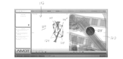
図面を参照し、特に図1~図3を参照すると、患者の解剖学的構造26を初期配置または望ましくない配置または配列(例えば、骨セグメント26(単一の骨のフラグメントまたは2つ以上の骨および/またはそのセグメントのいずれかであってもよい))から所望の配置または配列に操作するのに有用な例示的な外部整形外科固定装置10が示されている。図1~図3に示す装置10は、ヘキサポッドまたはスチュワートプラットフォームベースのリング固定装置であるが、本明細書に記載の方法およびシステムは、以下で説明するように、ヘキサポッドと同様に動作する他のタイプの整形外科外部固定システムに適用可能であり得る。いくつかの実施形態では、装置10は、国際PCT特許出願第PCT/US2017/017276号に開示されているヘキサポッドであってもよく、これは参照によりその全体が本明細書に明示的に組み込まれる。
Referring to the drawings, and in particular to FIGS. 1-3,
固定装置10は、少なくとも1つの近位または第1のプラットフォームのリング固定要素20、ならびに少なくとも1つの遠位または第2のプラットフォームのリングまたは固定要素30を含むことができる。装置10が患者に固定または結合されるときの装置10の配向に応じて、第1のプラットフォーム20が遠位プラットフォームであってもよく、第2のプラットフォーム30が近位プラットフォームであってもよいことに留意されたい。図2に示すように、第1および第2のプラットフォーム20、30は、それぞれ少なくとも1つの第1の骨セグメントおよび少なくとも1つの第2の骨セグメントなどのそれぞれの解剖学的構造26に取り外し可能に固定または結合され得る。図2に示すように、解剖学的構造26(例えば、骨セグメント)は、ピン構造14を介して第1および第2のプラットフォーム20、30と結合され得る。しかしながら、解剖学的構造と第1および第2のプラットフォーム20、30を取り外し可能に結合するために、その他の任意の装置または機構、例えば、限定はしないが、ワイヤ、両側ピン、ねじ、またはプラットフォームに対して骨セグメントを固定するのに有効な様々な結合装置などが利用されてもよい。さらに、解剖学的構造26は、初期配置(例えば、望ましくない配置)から所望の配置(例えば、修正された配置)への相対的な操作または動きから利益を得る任意の解剖学的構造であってもよいことに留意されたい。一例として、解剖学的構造26は、第1および第2のプラットフォーム20、30に結合される望ましくないまたは有害な配置で初期配置され、装置10を介して、骨セグメントの固定を促進および/または容易にする配置などの所望の配置になるように操作される、骨セグメントであってもよい。
The
図1~図3に示すように、第1および第2のプラットフォーム20、30は、6つの長さ調節可能なストラットアセンブリ11によって互いに結合されている。各ストラットアセンブリ11は、その第1の端部が第1の固定要素10に結合され、その第2の端部が3つの直交軸周りの3つの回転を可能にするジョイント13を介して第2の固定要素20に結合される。図1~図3に示すように、ストラットアセンブリ11は、第1および第2のプラットフォーム20、30の周りに(例えば、円周方向に)配置および結合されてもよく、各ストラットアセンブリ11は、プラットフォーム20、30および装置10の中心軸の周り(すなわち、患者の解剖学的構造の周り)の異なる位置で、ジョイント13を介して第1および第2のプラットフォーム20、30に取り付けられてもよい。このようにして、ストラットアセンブリ11の長さを調整することにより、固定装置10は、第2のプラットフォーム30に結合された少なくとも1つの第2の解剖学的構造に対して、第1のプラットフォーム20に結合された少なくとも1つの第1の解剖学的構造を、3つの直交軸のすべての平行移動(X、Y、Z位置)およびそれらの3つの直交軸の周りのすべての回転(ロール、ピッチ、ヨー)により、操作することができる(逆も同様である)。
As shown in FIGS. 1-3, the first and
ストラットアセンブリ11の構成は、ストラット11の軸方向の長さを調整する(すなわち、長くするおよび/または短くする)ことを可能にする任意の構成であってもよい。一例では、図1~図3に示すように、ストラットアセンブリ11は、少なくとも1つのジョイント13を介して第1および第2のプラットフォーム20、30の一方に結合されたロッド部分12と、少なくとも1つのジョイント13を介して第1および第2のプラットフォーム20、30の他方に結合されたバレル部分15と、を含んでもよい。ストラットアセンブリ11のロッド部分12およびバレル部分15は、それらの軸方向長さを調整し、それにより、第1および第2のプラットフォーム20、30ならびにそれらに固定された解剖学的構造26の距離および配向を調整するための調整機構16を介して互いに対して選択的に軸方向に並進移動可能であるように、移動可能に(例えば、ねじ式に)結合することができる。例えば、図2に示すように、第1および第2のプラットフォーム20、30は、初期配置または配列における固定機構14を介して第1および第2の骨セグメント26にそれぞれ固定されてもよい。
The configuration of
図3に示すように、ストラットアセンブリ11の軸方向の長さは、本開示の方法およびシステム(以下でさらに説明する)によって決定される調整処方または計画に従って経時的に増分的に調整して、第1および第2の骨セグメント26を所望の配置または配列になるように再配向、整列または操作することができる(一例では、第1および第2の骨セグメント26の固定を促進または達成することができる)。
As shown in FIG. 3, the axial length of
上述のように、6つのストラットアセンブリ11を備えたヘキサポッドなど、複数のストラットアセンブリ11を備えた外部固定装置の調整処方または計画は、解剖学的構造26を所望の配置になるように操作するために、ストラットアセンブリ11の経時的な増分的長さ調整で構成することができる。それにより、各ストラットアセンブリ11は、ストラット11を互いに区別し、調整処方に従ってその調整を可能にするために、固有の触覚および/または視覚インジケータを含んでもよい。例えば、ストラットアセンブリ11は、色分けおよび/または番号付けされてもよい。
As described above, the adjustment prescription or planning of an external fixation device with
調整処方の開発を支援または促進するために、装置10は、図1~図3に示すように、第1および第2のプラットフォーム20、30に関連する基準マーカー24を含んでもよい。基準マーカー24は、調整処方を決定する方法およびシステムのための、第1および第2のプラットフォーム20、30、ならびにストラットアセンブリ11などの、装置10の位置および配向または構成の基準点として利用できるように、装置10上の所定のまたは特定の位置に配置することができる。例えば、基準マーカー24は、図1~図3に示すように、第1および第2のプラットフォーム20、30の周りで円周方向に結合された球状部材であってもよい。いくつかの実施形態では、各基準マーカー24は、一対の隣接するストラットアセンブリ11に関連付けられ(例えば、近接して配置され)てもよく、第1または第2のプラットフォーム20、30の関連する部分の空間位置および/または一対の隣接するストラットアセンブリ11のジョイント13の関節点に関する基準を提供してもよい。いくつかの実施形態では、基準マーカー24は、図1~図3に示すように、第1および第2のプラットフォーム20、30の周りに均等に離間されてもよい。いくつかの実施形態では、基準マーカー24は、第1および第2のプラットフォーム20、30の対応する基準点または領域に関して固定された所定の空間的関係に配置されてもよく、第1および第2のプラットフォーム20、30の位置と配向、それにより、固定された所定の相対位置で、第1および第2のプラットフォーム20、30に結合されてもよいストラットアセンブリ11の位置、配向および長さが、方法およびシステムによって、関心のある解剖学的構造26と共に決定および表示することができる。このようにして、方法およびシステムは、基準マーカー24を利用して、解剖学的構造26および装置10の初期/現在および所望の配置をX線写真画像を介して表示および決定することができ、最終的に、以下でさらに説明するように、初期配置から所望の配置まで装置10を介して解剖学的構造26を操作するためのカスタマイズされた調整処方を決定することができる。基準マーカー24は、関心のある解剖学的構造26および装置10の他の部分に関してなど、X線写真画像で識別可能または区別可能な材料および/または形状で形成することができる。
To assist or facilitate the development of tailored prescriptions, the
図1~図3に示すように、基準マーカー24は、X線写真画像内の他のマーカーと判別可能または識別可能な方法で他のマーカー24と物理的に異なる少なくとも1つの固有のマーカー24’を含むことができる(例えば、他のマーカー24と比較して、より小さい、より大きい、形状が異なる、異なる素材/組成で構成されるなどの固有のマーカー24’)。固有のマーカー24’は、システムおよび方法によって利用されて、各ストラットアセンブリ11のアイデンティティを解読または決定することができる。例えば、第1および第2のプラットフォーム20、30の相対的な配向を決定するために、システムおよび方法によって固有のマーカー24’を利用することができ(例えば、第1のプラットフォーム20が遠位または近位のプラットフォームである場合)、それにより、(第1および第2のプラットフォーム20、30の配向に応じて)時計回りまたは反時計回りの相対位置に基づいてストラットアセンブリ11のアイデンティティを決定することができる。
As shown in FIGS. 1-3, the
本開示の外部固定装置(例えば、ヘキサポッド)調整処方の方法およびシステムは、少なくとも1つのコンピュータを利用してもよい。少なくとも1つのコンピュータは、例えば第1のコンピュータシステムなどの自律的に動作するコンピュータシステムであってもよい。外部固定装置の調整処方を決定および表示するために必要なすべての記憶、処理などは、第1のコンピュータシステムで達成されてもよい。他の実施形態では、外部固定装置の調整処方を決定および表示するために必要なタスクを達成するために、ネットワークを介して2つ以上のコンピュータに一緒にリンクされてもよい。例えば、第1および第2のコンピュータシステムは、ネットワークを介してリンクされ、協働して外部固定装置の調整処方を決定および表示してもよい。ネットワークは、ローカルエリアネットワークでも、インターネットなどのワイドエリアネットワークであってもよい。いくつかの実施形態では、タスクを達成するために実行されるすべてのプログラムは、コンピュータシステムの1つまたは複数で実行されてもよく、別のコンピュータシステムは単にデータを表示するために使用されてもよい。あるいは、プログラムはいくつかのコンピュータシステムで部分的に実行されてもよく、データと命令はネットワーク上で共有される。 The external fixation device (eg, hexapod) conditioning prescription methods and systems of the present disclosure may utilize at least one computer. The at least one computer may be an autonomously operating computer system, such as the first computer system. All storage, processing, etc. necessary to determine and display adjustment prescriptions for the external fixation device may be accomplished in the first computer system. In other embodiments, two or more computers may be linked together via a network to accomplish the tasks necessary to determine and display adjustment prescriptions for external fixation devices. For example, the first and second computer systems may be linked via a network and cooperate to determine and display adjustment prescriptions for the external fixation device. The network may be a local area network or a wide area network such as the Internet. In some embodiments, all programs executed to accomplish a task may be executed on one or more of the computer systems, while another computer system is simply used to display the data. good too. Alternatively, the program may be partially executed on several computer systems, with data and instructions shared over a network.
例えば、いくつかの実施形態では、本開示の方法およびシステムは、命令を実行し、ネットワークを介してデータをサーバーである第2のコンピュータシステムと共有するワールドワイドウェブブラウザを実行するコンピュータシステムを利用してもよい。これは、より複雑な、またはメモリを集中的に使用するプログラムを実行するためにより大きなコンピュータシステムが必要な状況で有利である。コンピュータ支援エンジニアリングプログラムは、そのようなプログラムの一例である。本発明のいくつかの実施形態では、サーバーコンピュータを使用して、コンピュータ支援エンジニアリングプログラムを実行し、ワールドワイドウェブサイトを提供またはホストする。コンピュータ支援エンジニアリングプログラムという用語には、従来のコンピュータ支援設計(CAD)プログラムと、製図だけでなく、プロジェクトの実施に役立つ設計ソリューションや他のデータを提供できるプログラムの両方が含まれる。例えば、少なくとも1つの外部固定装置の構成要素の動的な関係は、いくつかのそのようなプログラムで提供されてもよい。いくつかの実施形態では、コンピュータ支援エンジニアリングおよびウェブホスティング機能自体を別個のマシン専用にしてもよい。このような構成のサポートプログラムは、中央コンピュータでプログラムを更新するだけで更新できるため、提供されるプログラムの配列も有益である。したがって、ソフトウェアの更新ははるかに簡単になり、はるかに安価になる。 For example, in some embodiments, the methods and systems of the present disclosure utilize a computer system running a World Wide Web browser that executes instructions and shares data over a network with a second computer system that is a server. You may This is advantageous in situations where a larger computer system is required to run more complex or memory intensive programs. A computer aided engineering program is an example of such a program. In some embodiments of the invention, a server computer is used to run computer-aided engineering programs and to provide or host a World Wide Web site. The term computer-aided engineering program includes both traditional computer-aided design (CAD) programs and programs that can provide design solutions and other data to aid in the execution of a project, as well as drawings. For example, dynamic relationships of at least one external fixation device component may be provided in some such programs. In some embodiments, the computer aided engineering and web hosting functions themselves may be dedicated to separate machines. The array of programs provided is also beneficial, as the support program in such a configuration can be updated simply by updating the program at the central computer. Software updates are therefore much easier and much cheaper.
図4~図10は、本開示による外部固定装置の調整処方を決定および表示するコンピュータ支援方法およびシステム100を示している。調整処方の方法およびシステム100は、関心のある解剖学的構造として骨セグメント26に固定される、上述のヘキサポッド装置10などのヘキサポッド型外部固定装置を参照して説明および図示される。しかし、上述のように、また当業者には理解されるように、外部固定装置の調整処方を決定および表示する方法およびシステム100は、本開示の趣旨および範囲から逸脱することなく、任意の解剖学的構造に対して任意の外部固定装置(例えば、ヘキサポッドまたは他の外部固定装置)の調整処方を決定および表示することができる。
4-10 illustrate a computer-assisted method and
図4~図10に示すように、方法およびシステム100は、コンピュータプログラムおよびコンピュータシステムのグラフィカルユーザインターフェース(GUI)132を利用して、ユーザが方法およびシステム100を動作または実行できるようにすることができる。図4および図5に示すように、方法およびシステム100は、上述のヘキサポッド装置10などの骨セグメント26(または関心のある他の解剖学的構造)に固定されたヘキサポッド装置(または他の固定装置)の異なる配向の少なくとも2つのデジタルX線写真画像120を取得することを含むことができる含むことができる。X線写真画像120および/またはプログラムは、GUI132と同じコンピュータシステム、またはネットワーク接続されたコンピュータシステムに保存されてもよい。図5に示すように、GUI132を介して、ユーザは、X線写真画像120をアップロードまたはアクセスし、プログラムが調整処方を決定するために利用する画像120として、それらをタグ付けまたは識別することができる。例えば、図5に示すように、ユーザは、X線写真画像ファイルにアクセスし、X線写真画像120(またはその表示)をGUI132のウィンドウまたは指定エリアに配置する(またはその他の方法でX線写真画像ファイルを選択する)ことができる。X線写真画像120を含むファイル(すなわち、デジタルファイル)は、X線写真装置または中間ソースから直接になど、任意のソースから提供または取得することができる。
As shown in FIGS. 4-10, the method and
いくつかの実施形態では、X線写真画像120は、ヘキサポッド装置および患者(すなわち、解剖学的構造)の特定の配向または視点で撮影された画像としてラベル付けまたはその他の方法(ファイル自体および/またはプログラムを介してなど)で識別され得る。例えば、X線写真画像120は、認識された解剖学的平面(例えば、矢状面、正面、横断面または冠状面)または解剖学的軸(例えば、前後(A-P)または内側-外側(M-L))に沿って撮影されたものとして、ユーザによって(例えば、GUI32を介して)少なくともプログラム内で識別され得る。各X線写真画像120(またはX線写真画像120の視点)におけるヘキサポッドおよび骨セグメントの配向は、以下でさらに説明するように、ヘキサポッドおよび骨セグメントを示す操作可能な3次元モデルを作成する際に方法およびシステム100によって決定または考慮され得る。
In some embodiments, the
図4、図6Aおよび図6Bに示すように、方法およびシステム100は、取得またはアップロードされたX線写真画像120を利用し、ヘキサポッドの基準マーカーを識別する(ステップ104)ことができる。例えば、方法およびシステム100は、X線写真画像120(例えば、そのピクセル)を自動的に分析または解析し、画像120内の基準マーカーを識別するためにヘキサポッドの基準マーカーの形状に対応する画像120内の形状/構成を配置しようとすることができる。GUI132は、正確性を確保するために、X線写真画像120内の識別された基準マーカー124をユーザにグラフィカルに示すことができる。図6Aおよび図6Bに示すように、そのような基準マーカー識別104は、(画像120に示すヘキサポッドの基準マーカーの供給情報に基づいて)方法およびシステム100(例えば、プログラム)によって自動的に達成され得る。「自動」基準マーカー識別(ステップ104)プロセスの精度を確保するために、および/または方法およびシステム100によって自動的に検出されなかった(すなわち、プログラムによって自動的に検出されなかった)任意の基準マーカーの識別(ステップ104)を容易にするために、方法およびシステム100は、ユーザが、図6Bに示すように、GUI132を介して画像120内の基準マーカーの位置、サイズおよび/または形状を手動でグラフィカルに識別できるようにすることができる。次に、方法およびシステム100は、X線写真画像120のユーザ識別領域または位置を分析または解析して、その中の対応する基準マーカーを識別する(ステップ104)ことができる。いくつかの実施形態では、方法およびシステム100がX線写真画像120内の基準マーカーを識別できない場合には、方法およびシステム100は、ユーザ識別領域の中心を基準マーカーの中心として利用してもよい。
As shown in FIGS. 4, 6A and 6B, the method and
いくつかの実施形態では、方法およびシステム100は、識別された基準マーカー124、およびヘキサポッドの基準マーカーの予想または実際のサイズ、形状、および/または各画像120内のヘキサポッドの空間的方向/構成を決定するためのヘキサポッドの基準マーカーの構成に関する既知または供給された情報を介して、各X線写真画像120内のヘキサポッドの配向/構成を決定してもよい。例えば、方法およびシステム100は、潜在的に予想されるサイズおよび相対位置(固有のマーカー124’を含む)(方法とシステム100のプログラムにプリロードまたは提供されてもよい)と比較して、識別された基準マーカー124のそれぞれのサイズおよびX線写真画像120におけるそれらの相対位置を分析または計算することができ、各X線写真画像120に従って、ヘキサポッドのプラットフォームの相対位置および配向/構成を決定し、それによってそのストラットを決定することができる。
In some embodiments, the method and
例えば、各画像120の透視情報は方法およびシステム100により決定できるので、各画像120の平面内の基準の位置の動きおよび画像120からの距離を決定することができる。そのような情報は、各画像120内のヘキサポッドの基準の3次元データを提供する。方法およびシステム100は、この3次元データを利用して基準を3次元空間に配置し、それらの間の距離を計算して空間に三角形を作成することができる。次いで、方法およびシステム100は、この三角形を外接円で囲むことができる。この円の直径または半径は、精度を確保するために、ヘキサポッドのプラットフォームの直径または半径としてユーザに提供されてもよい。直径または半径が実際に使用されているプラットフォームと一致しない場合には、ユーザはこの推定直径または半径を実際の直径または半径に置き換えることができる(あるいは実際の直径または半径を最初に入力してもよい)。方法およびシステム100は、実際の直径または半径を計算された直径または半径と比較することができ、本明細書で説明したものと同じアルゴリズムを再実行することにより精度を高めるためにさらなるスケーリング調整を体積スケーリングに対して行うことができる。
For example, since the perspective information of each
さらに、方法およびシステム100は、各画像120のこの3次元データを利用して、四面体を作成することができ、そのベースは、識別された基準124中心の中心の位置であり、そのエッジは、修正された基準の実際の3次元位置と交差し、焦点で終了する。次いで、方法およびシステム100は、この焦点から画像中心への軸を作成することができ、これは、画像120の視点を記述または示すベクトルであり得る。このプロセスは、各画像120について繰り返されてもよい。次いで、方法およびシステム100は、画像120のベクトル間の角度を計算して、2つのX線写真画像120間の角度を決定することができ、これを用いて各画像120に対するヘキサポッド(例えば、プラットフォームおよびストラット)の空間配向を決定することができる。しかし、当業者が理解するように、各画像120内の識別された基準マーカー124からヘキサポッドの空間配向/構成を決定するその他の方法またはプロセスを利用できることに留意されたい。
Additionally, the method and
図4に示すように、いくつかの実施形態では、方法およびシステム100は、GUI132内のヘキサポッドの少なくとも一部(例えば、少なくともそのプラットフォーム)の決定された配向/構成をグラフィカルに表示または例示して、決定された方向/構成が正確であることをユーザが確認できるようにすることができる。いくつかのそのような実施形態では、ヘキサポッドの部分は、ヘキサポッドの配向/構成を示す3次元モデルで提示されてもよい。
As shown in FIG. 4, in some embodiments the method and
X線写真画像120のラベル付きまたは予め識別された視点(すなわち、ヘキサポッドおよび骨セグメントの配向)を利用する代わりに、および/またはそれに加えて、方法およびシステム100は、X線写真画像120間の視点/配向の差を決定するように構成されてもよい。例えば、方法およびシステム100は、識別された基準マーカー124および各X線写真画像120のヘキサポッドの基準マーカーの既知の情報を介して、ヘキサポッドの決定された配向/構成を比較して、X線写真画像120間の視点/配向の相対的な差を決定することができる。このようにして、方法およびシステム100は、X線写真画像120の視点/配向を決定し、以下でさらに説明するように、ヘキサポッドおよび骨セグメントを示す操作可能な3次元モデルを作成する際にそのような情報を潜在的に利用することができる。
Instead of and/or in addition to utilizing labeled or pre-identified viewpoints (i.e., hexapod and bone segment orientations) of the
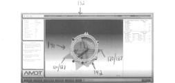
図4に示すように、方法およびシステム100は、GUI132上にX線写真画像120を表示または提示し、ユーザがX線写真画像120内の骨セグメント(または関心のある他の解剖学的構造)の軸をデジタル的に識別することを可能にすることができる。例えば、方法およびシステム100は、GUI132上にX線写真画像120を表示し、図4および図7に示すように、ユーザが各X線写真画像120内の骨セグメントの軸136に沿って線を引くまたは形成することを可能にすることができる。方法およびシステム100は、GUI132上にX線写真画像120を表示または提示し、ユーザが、X線写真画像120内の骨セグメント(または関心のある他の解剖学的構造)を含む識別された軸に隣接する画像の一部をデジタルで識別できるようにすることもできる。例えば、方法およびシステム100は、X線写真画像120をGUI132に表示し、図7に示すように、ユーザが、骨セグメントを含む画像120の部分を含む指示された各軸136から延在するウィンドウまたは画定空間138を描画または形成できるようにすることができる。
As shown in FIG. 4, the method and
骨セグメントの軸136および各X線写真画像120内の画像120の選択された部分138(および骨セグメントを含むX線写真画像120の選択された部分)は、図4、図8Aおよび図8Bに示すように、方法およびシステム100により利用されて、画像120およびヘキサポッドモデル142から骨セグメントを示す操作可能な3次元モデル140を形成することができる。例えば、指示された軸136は、X線写真画像120に垂直に延びる平面を表してもよい。図8Aおよび図8Bに示すように、各骨セグメントのこれらの平面を3次元軸に沿って交差させて、X線写真画像120の選択された部分を3次元モデル140に配置することができる。X線写真画像120が直交する場合、各骨セグメント(およびX線写真画像120のそれぞれの選択された部分)の平面は、指示された軸136に沿って90度で交差し、それに応じてX線写真画像120の対応する部分を配置することができる。しかしながら、上記のように、X線写真画像120は直交しない場合があり、方法およびシステム100は画像120の視点/配向の差を決定してもよい。方法およびシステム100は、画像120の視点/配向の決定された差を利用して、それに応じて(すなわち、画像120の「真の」視点/配向に従って)平面と交差することができ、それにより、各骨セグメントの「真の」3次元軸に沿ったX線写真画像120のそれぞれの選択された部分と交差することができる。さらに、図4、図8Aおよび図8Bに示すように、3次元モデル140は、上述のX線写真画像120内の識別された基準124によって決定される予想ヘキサポッドに対応するモデルヘキサポッド142を含むことができる。
The
図4、図8Aおよび図8Bに示すように、3次元モデル140は、それにより、画像120の交差する選択された部分124によって示される3次元骨セグメントと、画像120で示されるようにその初期配置におけるモデルヘキサポッド142と、から構成することができる。3次元モデル140は、GUI132上に表示することができ、ユーザは、初期配置から(モデルヘキサポッド142のプラットフォームと共に)互いに対して対応する3次元軸に沿って3次元骨セグメントを操作することができる。例えば、方法およびシステム100は、ユーザがGUI120を利用して、図9A~図9Cに示すように、骨セグメントの所望の3次元配置への所定の経路または経路に従って、骨セグメントの3次元軸の少なくとも一方を他方に対して操作できるようにすることができる。
As shown in FIGS. 4, 8A and 8B, the three-
図4および図9A~図9Cに示すように、ユーザは、GUI132を利用して、ユーザ定義の中間点、セグメントまたは段階144に沿って骨セグメントモデルの位置および配向を互いに対して操作することができる。例えば、ユーザは、図9A~図9Cに示すように、GUI132を利用して、骨セグメントモデルを初期配置から第1のユーザ定義中間点の配置に再配置する骨セグメントモデルの第1の操作段階144(すなわち、それらの3次元軸の相対移動)を形成することができる。第1のユーザ定義中間点の配置144から、ユーザは、図9A~図9Cに示すように、第1のユーザ定義中間点の配置から第2のユーザ定義中間点の配置に骨セグメントモデルを再配置する骨セグメントモデルの第2の操作段階144に入ることができる。同様に、ユーザは次に、骨セグメントモデルを第2のユーザ定義中間点の配置から第3のユーザ定義中間点の配置に再配置する骨セグメントモデルの第3の操作段階144に入ることができる。このようにして、ユーザは、初期配置から所望の配置までの骨セグメントの移動の経路またはコースを決定することができる。
As shown in FIGS. 4 and 9A-9C, the user can utilize the
図8A~図9Cに示すように、ヘキサポッドモデル142は、定義された中間点144に沿った骨セグメントモデルの相対的再配置または移動に対応して調整することができる。このようにして、方法およびシステム100は、骨セグメントおよびそれに固定されたプラットフォームが初期配置から所望の配置に再配置されるにつれて、ヘキサポッドモデルのストラット長の変化を計算または決定することができる。図10に示すように、方法およびシステム100は、定義された中間点または経路144に沿った初期配置から所望の配置への骨セグメントの移動を実現するヘキサポッドのための調整処方150(すなわち、ストラットの長さの増分調整、またはそのようなストラットの長さ調整を実施するための指示)を、GUI132上に表示し、別のGUI上に表示し、あるいはその他の方法で出力(例えば、物理的形態、コンピュータメモリなどに出力)することができる。これにより、ユーザまたは患者は、調整処方150に従って患者の実際のヘキサポッドのストラットを段階的に調整し、定義された中間点144に沿って初期配置から所望の配置に骨セグメントを移動させることができる。このようにして、ユーザまたは患者は、調整処方150によって提供される調整を利用して、実際のヘキサポッドのストラットを調整し、骨セグメントを所望の配置に移動または操作することができる。
As shown in FIGS. 8A-9C, the
本明細書で具体的に詳述した本発明の実施形態はヘキサポッド型外部固定構造を含むが、本発明の装置および方法は多くの種類の外部固定装置に適用可能であることに留意することが重要である。上記の参照により組み込まれた特許および文書には、ヘキサポッドまたはスチュワートプラットフォームベースの外部固定器の多くの変形例が記載されている。本発明の装置および方法は、これらの変形例のいずれかで有用であって、これらの変形例には、部分的リングのみを含むか、ストラットの数が少ないか、あるいは外部固定装置に組み込まれたまたは外部固定装置とは別個に構築されたクランプおよびバー構造を含む外部固定器が含まれる。本発明の装置および方法は、米国特許第5,702,389号に開示されている片側性装置などの片側性整形外科用外部固定装置を構成するのに等しく有用である。図示された装置には、6ストラットのスチュワートプラットフォームも組み込まれている。しかし、本発明の特許請求の範囲内の片側性整形外科用外部固定装置は、必ずしもスチュワートプラットフォームを含むとは限らない。本発明の特許請求の範囲を備えた装置は、装置が上述の装置の並進および回転の程度の一部またはすべてを模倣することを可能にする調整の組み合わせを単に含むことができる。 Note that although the embodiments of the invention specifically detailed herein include hexapod external fixation structures, the apparatus and methods of the present invention are applicable to many types of external fixation devices. is important. The patents and documents incorporated by reference above describe many variations of hexapod or Stewart platform-based external fixators. The devices and methods of the present invention are useful with any of these variations, including only partial rings, fewer struts, or integrated into the external fixation device. Also included is an external fixator comprising a clamp and bar structure constructed separately from the external fixator. The devices and methods of the present invention are equally useful in constructing unilateral orthopedic external fixation devices such as the unilateral device disclosed in US Pat. No. 5,702,389. The illustrated device also incorporates a six-strut Stewart platform. However, a unilateral orthopedic external fixation device within the scope of the claims of the present invention does not necessarily include a Stewart platform. A device comprising the claims of the present invention may simply include a combination of adjustments that allow the device to mimic some or all of the degrees of translation and rotation of the device described above.
方法およびシステムのいくつかの実施形態では、各X線写真画像内のヘキサポッドの識別されたデジタル基準は、3次元モデルの作成前に調整されて、ヘキサポッドおよび骨セグメントの配置のより正確な表現、および、それにより、より正確で効果的な修正処方を提供することができる。具体的には、各X線写真画像内の基準の歪みを修正することにより、ヘキサポッドおよび骨セグメントのより正確な3次元モデル(前述のように、ユーザが修正処方を決定するために使用される)を提供することができる。 In some embodiments of the method and system, the identified digital fiducials of the hexapods in each radiographic image are adjusted prior to creation of the three-dimensional model to provide more accurate placement of the hexapods and bone segments. Representations and thereby more accurate and effective corrective prescriptions can be provided. Specifically, by correcting fiducial distortions in each radiographic image, more accurate three-dimensional models of the hexapods and bony segments (used to determine the correction prescription by the user, as described above) can be obtained. ) can be provided.
上述のように、この方法およびシステムは、患者に固定されたヘキサポッド型外部固定装置の異なる配向のX線写真装置から、または異なる相対的視点から撮影された2つのデジタルX線写真画像を利用することができる。画像を作成するために、典型的なX線写真装置は、患者の骨セグメントに固定されたヘキサポッドに向けて投影される発生器を介してX線(または他の形式の「電磁放射」)を生成する。特定の量のX線は、その密度と組成に応じて、ヘキサポッドと患者に吸収される。ヘキサポッドと患者を透過するX線は、「検出器」(例えば、「写真フィルム」またはデジタル検出器)によってヘキサポッドと患者の背後で取り込まれる。検出されたX線は、検出されたX線の相対量を示す画像として表示される。この技術によるこの平坦な2次元画像の生成は、しばしば「投影X線写真」と呼ばれる。 As described above, the method and system utilize two digital radiographic images taken from different orientations of the radiographic device of a hexapod external fixator fixed to the patient or from different relative viewpoints. can do. To create an image, a typical radiographic device emits x-rays (or other forms of "electromagnetic radiation") through a generator projected onto hexapods fixed to the patient's bony segments. to generate A certain amount of X-rays is absorbed by the hexapod and the patient, depending on their density and composition. X-rays passing through the hexapod and patient are captured behind the hexapod and patient by a "detector" (eg, "photographic film" or digital detector). The detected x-rays are displayed as an image showing the relative amount of detected x-rays. The production of this flat two-dimensional image by this technique is often referred to as "projection radiography".
しかし、投影X線撮影では、通常、画像の中心に対してサイズと位置の両方が拡大された特定のアーチファクトを有する画像が生成される。この倍率の大きさは、X線が生成焦点または領域から放出される可能性があるため、検出器からのアーチファクトの距離の線形関数であり得る。図11に示すように、検出器112からより遠くに位置するアーチファクト110a、110bは、生成点/領域116からのX線114の発散により検出器112に比較的近くに位置するアーチファクト110c、110dよりも大きく拡大される。このようにして、検出器112からより遠くに位置するアーチファクト110a、110bは、検出器112に比較的近くに配置されたアーチファクト110c、110dのそれと比較して、検出器112 114で吸収されたX線のより大きな影を投じる(それにより、検出されるX線114が少なくなる)。
However, projection radiography typically produces images with certain artifacts that are magnified in both size and position relative to the center of the image. The magnitude of this magnification can be a linear function of the distance of the artifact from the detector, since x-rays may be emitted from the focal point or region of origin. As shown in FIG. 11,
上述のように、いくつかの実施形態では、方法およびシステムは、患者の骨セグメントおよび他の解剖学的構造の周りに配置された複数の球状基準のアレイ(例えば、各プラットフォームに結合された3つの基準を持つ合計6つの基準)を含むヘキサポッド型外部固定装置の修正処方を生成するように構成されてもよい。X線写真画像を生成するために投影X線撮影で画像を作成する場合、各基準マーカーは異なる位置にあるため、X線検出器からの距離は基準ごとに異なり、したがって倍率は対象の解剖学的構造(すなわち、骨セグメント)の倍率とは個別に異なってくる。基準の倍率と患者の解剖学的構造(特に、骨セグメント)のこのような違いを考慮するために、本方法およびシステムは、X線写真画像と識別された基準の位置とサイズを修正し、最終的に、(ヘキサポッドと骨セグメントの3次元モデルを介して)骨セグメントの所望の配置をより正確にもたらす修正処方を作成する、歪み修正方式を実行することができる。 As noted above, in some embodiments, the methods and systems include arrays of multiple spherical fiducials (e.g., 3 datums coupled to each platform) positioned around bony segments and other anatomical structures of the patient. A total of six criteria with six criteria) may be configured to generate a revised prescription for a hexapod external fixation device. When imaging with projection radiography to produce a radiographic image, each fiducial marker is at a different location, so the distance from the x-ray detector is different for each fiducial, and therefore the magnification depends on the subject's anatomy. The magnification of the physical structures (ie, bone segments) will vary individually. To account for such differences in fiducial magnification and patient anatomy (particularly bony segments), the method and system modify the position and size of the radiographic image and the identified fiducial, Ultimately, a distortion correction scheme can be implemented (via the hexapod and the 3D model of the bone segment) to create a correction prescription that more accurately results in the desired placement of the bone segment.
図12~図15に示すように、いくつかの実施形態では、方法およびシステムは、各X線写真画像の体積歪み全体および/または基準固有のサイズおよび位置歪みを考慮する歪み修正方式200を使用することができる。いくつかの実施形態では、方法およびシステムは、X線写真画像を修正して、識別された基準の寸法の合計と基準直径の予想または実際の合計の比較は、骨セグメント(すなわち、関心のある囲まれた解剖学的構造)の拡大率に比較的密接に対応するバルクまたは体積倍率に達することを認識することにより、その体積歪みを補正する。例えば、図12~図15に示すように、いくつかの実施形態では、基準測定単位当たりのピクセルでの画像の体積スケールを決定するために、何らかの測定単位(例えば、インチ、ミリメートルなど)で、患者に固定されているヘキサポッドの実際の基準マーカーの寸法の予想される合計に対するピクセルでのX線写真画像120内で発見された基準マーカー124の合計の比を決定すること(ステップ222)によって、歪み修正方式200は、各X線写真画像120を修正して、その体積歪み、および、それにより、骨セグメント126(および/または関心のある他の解剖学的構造)を補正することができる。実際の基準マーカーが実質的に球形である場合など、いくつかの実施形態では、基準の直径を合計して比較することができる。X線写真画像120内の識別された基準マーカー124は、図13および図15に示すように、X線の発散性のために少なくとも実質的に楕円形であってもよいことに留意されたい。そのような実施形態では、ピクセルのX線写真画像120内の識別された基準マーカー124の短軸を合計し、ヘキサポッドの実際の基準マーカーの直径の予想合計と比較して、その比を決定する(ステップ122)ことができる。
As shown in FIGS. 12-15, in some embodiments, the methods and systems employ a
図12に示すように、歪み修正方式200は、X線写真画像120の画像測定単位当たりのピクセルにおける予想解像度に対する基準測定単位当たりのピクセルの比を決定する(ステップ224)こともできる。画像の測定単位あたりのピクセルの予想画像解像度は、画像のデジタルファイル内に含まれるパラメータによって決定されてもよい。また、図12に示すように、歪み修正方式200は、X線写真画像120の体積スケール、したがって体積スケール骨セグメント126(および/または関心のある他の解剖学的構造)を決定する(ステップ226)ことを含んでもよい。X線写真画像120の体積スケールを決定するステップ226は、基準測定単位当たりのピクセルでの画像の体積スケールの比を、X線写真画像120の画像測定単位当たりのピクセルでの予想解像度に対する基準測定単位当たりのピクセルの比に対して決定するステップを含んでもよい(すなわち、基準測定単位あたりのピクセルの、予想解像度に対するX線写真画像120の画像測定単位当たりのピクセルの比を、基準測定単位当たりのピクセルでの画像のメトリックスケールに分割する)。
As shown in FIG. 12, the
歪み修正方式200は、X線写真画像120の体積スケールを利用して、それに応じてX線写真画像120をスケーリングする(ステップ228)ことができる。例えば、X線写真画像120全体は、画像120の中心から計算された体積スケールに従ってスケーリングする(ステップ228)ことができる。それにより、体積スケールに従ってX線写真画像120をスケーリングする(ステップ228)ことにより、X線写真画像120全体を縮小または拡大し、最初に識別された基準124は、図13~図15に示すように、それらの歪んだ位置から、体積スケーリングされた基準128としてのスケーリングされた位置に移動する。さらに、X線写真画像120の他のすべてのアーチファクトも、体積スケールに従って画像120の縮小または拡大に基づいて移動または再配置される。この体積スケール決定プロセスは、各画像120について繰り返されてもよい。このようにして、例えば、方法およびシステムは、全体として各X線写真画像120の体積歪みを補正する歪み修正方式200を採用してもよい。
The
上述したように、図13~図15に示すように、いくつかの実施形態では、方法およびシステムは、(潜在的には、上述のように各X線写真画像全体の体積歪みを考慮することに加えて)基準固有のサイズおよび位置歪みを補正する歪み修正方式200を使用することができる。いくつかの実施形態では、方法およびシステムは、ヘキサポッドの各基準がX線検出器に対して固有の位置および距離として配置され、それにより異なるように歪められたため、識別された基準124のサイズおよび位置を個別にまたは具体的に修正することができる。図12~図15に示すように、歪み修正方式200は、予想される基準寸法(すなわち、ヘキサポッドの物理的基準マーカーの実際の寸法)の個々の基準比を、対応する体積スケーリングされた基準128の寸法に対して個別に決定する(ステップ230)ことによって(すなわち、予想される基準寸法と、対応する体積スケーリングされた基準128の寸法との個々の基準比)、基準固有のサイズおよび位置歪みを補正することができる。上述のように、ヘキサポッドの実際の基準は球形であってもよく、体積スケーリングされた基準128は楕円形であってもよい。そのような実施形態では、個々の基準比は、予想基準直径を、対応する体積スケーリングされた基準128の直径(例えば、非円形の場合は短径)に分割することにより決定する(ステップ230)ことができる。
As described above, and as shown in FIGS. 13-15, in some embodiments, the methods and systems may (potentially consider the volumetric distortion across each radiographic image as described above). ), a
個々の基準比が決定されると、図12~図15に示すように、歪み修正方式200は、個々の比を利用して(ステップ232)、具体的にスケーリングされた位置にあり、予想される基準直径(すなわち、ヘキサポッドの対応する物理的基準マーカーの実際の直径)の各基準に対して新しいデジタルまたはグラフィックの個別にスケーリングされた基準マーカー130を作成することができる。例えば、ヘキサポッドの各基準の実際の直径に対応する個別にスケーリングされたデジタルの基準円またはマーカー130が、X線写真画像120上に形成され得る。個々にスケーリングされた基準マーカーまたは円130は、図13~図15に示すように、個々の基準比に基づいて、体積スケーリングされた基準128に対して配置されてもよい。例えば、個別にスケーリングされた基準マーカー130は、図13~図15に示すように、個々の基準比に基づいて、X線写真画像120の焦点または中心に近い、または遠く離れた、体積スケーリングされた基準128の中心から半径方向に移動または位置決めされてもよい。X線写真画像120の焦点または中心を決定または近似することができる。例えば、X線写真画像120の焦点または中心は、X線写真画像120の数学的中心(すなわち、画像120のxおよびy寸法/方向の中心)であってもよい。別の例として、X線写真画像120の焦点または中心は、体積スケーリングされた基準128を介して決定されてもよい。いくつかのそのような実施形態では、X線写真画像120内の体積スケーリングされた基準128は楕円形であってもよく、体積スケーリングされた基準128の長軸は、X線写真画像120の焦点または中心を表し得るそれらの交点まで延長されてもよい。しかしながら、X線写真画像120の焦点または中心を識別するその他の任意の方法が利用されてもよい。
Once the individual reference ratios are determined, the
個別にスケーリングされた基準マーカー130は、図13~図15に示すように、体積スケーリングされた基準128の中心の位置と個々の基準比に基づいて、体積スケーリングされた基準128の中心とX線写真画像120の焦点または距離の中心との間に延在する方向に沿って半径方向に移動または位置決めされてもよい。例えば、個々の基準比が1.0未満である場合、対応する個々にスケーリングされた基準マーカー130の中心は、図12~図14に示すように、X線写真画像120上で、X線写真画像120の焦点または中心と、個々の基準比に応じて画像中心に近づく体積スケーリングされた基準128(図13参照)の中心と、の間に延在する半径方向に沿って配置されてもよい。そのようなシナリオでは、対応する個別にスケーリングされた基準マーカー130の中心は、図13~図15に示すように、X線写真画像120の焦点または中心と、対応する体積スケーリングされた基準128の中心との間に延在する半径方向に沿って(図13を参照)、X線写真画像120の焦点または中心から距離を置いて配置されてもよく、それは、X線写真画像120の焦点または中心と、対応する個々の基準比を乗じた、対応する体積スケーリングされた基準128の中心との間の半径方向距離に等しい(それにより、X線写真画像120の焦点または中心と、対応する体積スケーリングされた基準128の中心と、の間の半径方向距離よりも小さくなる)。同様に、個々の基準比が1.0よりも大きい場合、図13~図15に示すように、対応する個々にスケーリングされた基準マーカー130の中心は、X線写真画像120上で、X線写真画像120の焦点または中心と、個々の基準比に従って画像中心からさらに離れた対応する体積スケーリングされた基準128(図13参照)の中心との間に延在する半径方向に沿って配置されてもよい。このようにして、このようなシナリオでは、対応する個別にスケーリングされた基準マーカー130の中心は、図13~図15に示すように、X線写真画像120の焦点または中心と、対応する体積スケーリングされた基準128の中心との間に延在する半径方向に沿って(図13を参照)、X線写真画像120の焦点または中心から距離を置いて配置されてもよく、それは、X線写真画像120の焦点または中心と、対応する個々の基準比を乗じた、対応する体積スケーリング基準128の中心との間の半径方向距離に等しい(それにより、X線写真画像120の焦点または中心と、対応する体積スケーリング基準128の中心と、の間の半径方向距離よりも大きくなる)。
The individually scaled
個々にスケーリングされた基準マーカー130は、図14および図15に示すように、各X線写真画像120に対してこのプロセスを介して形成され得る。個々の基準比が決定されると、歪み修正方式200により、あたかもX線写真画像120を作成するために利用されるX線発生器が(検出器からある有限の距離とは対照的に)無限遠にあるかのように各X線写真画像120の直線座標(例えば、xおよびy座標)に配置された個別にスケーリングされた基準マーカー130を得ることができる。図15に示すように、個別にスケーリングされた基準マーカー130および体積スケーリングされた骨セグメントおよび/または関心のある他の解剖学的構造を有するX線写真画像120を組み合わせて、患者のヘキサポッドの基準の実際の座標を計算し、ヘキサポッドおよび骨セグメントおよび/または関心のある他の解剖学的構造の3次元モデルを形成することができ、これを上述のように修正処方を決定するために利用することができる。
Individually scaled
当業者には明らかなように、本開示の発明は、外部固定装置およびヘキサポッドおよび骨セグメントモデリングの分野を含む解剖学的構造のコンピュータモデリングの分野において著しい改善を提供する。さらに、本開示の発明は、X線写真画像の歪み修正の分野を含む、X線写真画像作成の分野における顕著な改善を提供する。本開示の発明はまた、ヘキサポッド調整処方の分野を含む、外部固定装置の調整処方決定の分野において著しい改善を提供する。 As will be appreciated by those skilled in the art, the disclosed invention provides significant improvements in the field of computer modeling of anatomy, including the fields of external fixation devices and hexapod and bony segment modeling. Further, the disclosed invention provides significant improvements in the field of radiographic imaging, including the field of radiographic image distortion correction. The disclosed invention also provides significant improvements in the field of external fixation device adjustment prescription determination, including the area of hexapod adjustment prescription.
当業者は、本発明の態様がシステム、方法、および/またはコンピュータプログラム製品で具体化され得ることを認識するであろう。いくつかの実施形態では、本発明の態様は、ハードウェアで完全に、ソフトウェアで完全に(例えば、ファームウェア、常駐ソフトウェア、マイクロコードなど)、あるいは本明細書では「システム」と呼ばれ、回路および/またはモジュールを含むソフトウェアとハードウェアの組み合わせで具体化することができる。 Those skilled in the art will recognize that aspects of the present invention can be embodied in systems, methods and/or computer program products. In some embodiments, aspects of the present invention are entirely in hardware, entirely in software (e.g., firmware, resident software, microcode, etc.), or referred to herein as a "system", comprising circuits and / Or can be embodied in a combination of software and hardware including modules.
図16は、本発明の1つまたは複数の態様を組み込み使用するためのコンピュータシステムの一例を示している。コンピュータシステム300は、物品を積層製造するために使用されるコンピュータシステムなどの物品製造および/または修理施設のコンピュータシステム、および/または物品を製造するためにAM装置またはデバイスによって使用されるデータを生成するためのコンピュータシステムであってもよい。図7のコンピュータシステム300は、上述のプロセスを実行するためのプログラムコードなどのプログラムコードを格納および/または実行するのに適していてもよく、バス320を介してメモリ304に直接または間接的に結合された少なくとも1つのプロセッサ302を含む。動作中、プロセッサ302は、プロセッサによる実行のための命令をメモリ304から取得してもよい。メモリ304は、プログラムコードの実際の実行中に使用されるローカルメモリ、バルク記憶装置、およびプログラムコードの実行中にバルク記憶装置からコードを取得しなければならない回数を減らすために少なくともいくつかのプログラムコードの一時記憶装置を提供するキャッシュメモリを含んでもよい。メモリ304の例の非限定的なリストには、ハードディスク、ランダムアクセスメモリ(RAM)、読み取り専用メモリ(ROM)、消去可能プログラマブル読み取り専用メモリ(EPROMまたはフラッシュメモリ)、光ファイバ、ポータブルコンパクトディスク読み取り専用メモリ(CD-ROM)、光学記憶装置、磁気記憶装置、または前述の任意の適切な組み合わせが含まれる。メモリ304は、オペレーティングシステム305と、回路設計のデジタルレイアウトの調整を行うなど、本明細書で説明する態様を実行するための実行用の1つまたは複数のプログラムなどの1つまたは複数のコンピュータプログラム306と、を含んでもよい。
FIG. 16 illustrates an example computer system for incorporating and using one or more aspects of the present invention. The
入力/出力(I/O)装置312、314(周辺機器など)は、直接またはI/Oコントローラ310を介してシステムに結合されてもよい。ネットワークアダプタ308をシステムに結合して、介在するプライベートまたはパブリックネットワークを介してコンピュータシステムを他のコンピュータシステムに結合できるようにすることもできる。モデム、ケーブルモデム、およびイーサネットカードは、現在利用可能なネットワークアダプタ308のほんの一部である。一例では、ネットワークアダプタ308は、本発明の態様を促進するために、リモートソースからのデータの取得を促進する。
Input/output (I/O)
コンピュータシステム300は、1つまたは複数のデータベースを有する記憶装置316(例えば、磁気ディスクドライブ、光ディスクドライブ、テープドライブなどの不揮発性記憶装置エリア)に結合されてもよい。記憶装置316は、内部記憶装置または接続された記憶装置またはネットワークアクセス可能な記憶装置を含んでもよい。記憶装置316内のコンピュータプログラムは、メモリ304にロードされ、プロセッサ302によって実行されてもよい。
コンピュータシステム300は、図示されているよりも少ない構成要素、本明細書に示されていない追加の構成要素、または示されている構成要素と追加の構成要素の何らかの組み合わせを含んでもよい。コンピュータシステム300は、メインフレーム、サーバー、パーソナルコンピュータ、ワークステーション、ラップトップ、ハンドヘルドコンピュータ、スマートフォン、テーブル、または他のモバイル装置、電話装置、ネットワーク機器、仮想化装置、記憶装置コントローラなどのコンピューティング装置を含んでもよい。
加えて、上述のプロセスは、コンピューティング環境の一部として協調して動作する複数のコンピュータシステム300によって実行されてもよい。
Additionally, the processes described above may be performed by
いくつかの実施形態では、本発明の態様は、コンピュータ可読媒体で具体化されるコンピュータプログラム製品の形態をとることができる。コンピュータ可読媒体には、コンピュータ可読プログラムコードが組み込まれていてもよい。様々なコンピュータ可読媒体またはそれらの組み合わせが利用されてもよい。例えば、コンピュータ可読媒体は、コンピュータ可読記憶媒体を含むことができ、その例には、(限定はしないが)1つもしくは複数の電子、磁気、光学、または半導体システム、装置、またはデバイス、または任意の適切な上記の組み合わせが含まれる。コンピュータ可読記憶媒体の例には、例えば、1つまたは複数のワイヤを有する電気接続、ポータブルコンピュータディスケット、ハードディスクまたは大容量記憶装置、ランダムアクセスメモリ(RAM)、読み取り専用メモリ(ROM)、および/またはEPROMまたはフラッシュメモリなどの消去可能プログラム可能な読み取り専用メモリ、光ファイバ、ポータブルコンパクトディスク読み取り専用メモリ(CD-ROM)、光学記憶装置、磁気記憶装置(テープデバイスを含む)、または上記の任意の適切な組み合わせが含まれる。コンピュータ可読記憶媒体は、プロセッサなどの命令実行システム、装置、または装置によって使用するための、またはそれらに関連するプログラムコードを含むまたは格納できる有形媒体を含むように定義される。したがって、コンピュータ可読媒体の中に/その上に格納されたプログラムコードは、プログラムコードを含む製品(「コンピュータプログラム製品」など)を作製する。 In some embodiments, aspects of the invention may take the form of a computer program product embodied in a computer-readable medium. The computer readable medium may have computer readable program code embodied therein. Various computer readable media or combinations thereof may be utilized. For example, computer-readable media may include computer-readable storage media, including (without limitation) one or more electronic, magnetic, optical, or semiconductor systems, apparatus, or devices, or any any suitable combination of the above. Examples of computer-readable storage media include, for example, an electrical connection having one or more wires, a portable computer diskette, a hard disk or mass storage device, a random access memory (RAM), a read only memory (ROM), and/or erasable programmable read-only memory such as EPROM or flash memory, optical fiber, portable compact disc read-only memory (CD-ROM), optical storage, magnetic storage (including tape devices), or any suitable of the above combinations are included. A computer-readable storage medium is defined to include any tangible medium that contains or can store program code for use by, or associated with, an instruction execution system, device, or device, such as a processor. Thus, program code stored in/on a computer-readable medium creates a product (such as a "computer program product") containing the program code.
ここで図17を参照すると、一例では、コンピュータプログラム製品400は、例えば、本発明の1つまたは複数の態様を提供および促進するためのコンピュータ可読プログラムコード手段またはロジック404を格納する1つまたは複数のコンピュータ可読媒体402を含む。
Referring now to FIG. 17, in one example, a computer program product 400 includes, for example, one or more computer readable program code means or
コンピュータ可読媒体に含まれる/格納されるプログラムコードは、コンピュータシステム(コンピュータ、その構成要素を含むコンピュータシステムなど)および/または他の装置によって取得および実行され、コンピュータシステム、その構成要素、および/または他の装置を特定の方法で動作/機能させることができる。プログラムコードは、無線、有線、光ファイバ、および/または無線周波数を含む(ただしこれらに限定されない)適切な媒体を使用して送信することができる。本発明の態様を実行、達成、または促進するための動作を実行するためのプログラムコードは、1つまたは複数のプログラミング言語で書かれていてもよい。いくつかの実施形態では、プログラミング言語は、C、C++、C#、Javaなどのオブジェクト指向および/または手続き型プログラミング言語を含む。プログラムコードは、ユーザのコンピュータ上で完全に実行されるか、ユーザのコンピュータから完全にリモートで実行されるか、一部がユーザのコンピュータ上で、一部がリモートコンピュータ上で実行されてもよい。いくつかの実施形態では、ユーザのコンピュータとリモートコンピュータは、ローカルエリアネットワーク(LAN)またはワイドエリアネットワーク(WAN)などのネットワークを介して、および/または外部コンピュータを介して(例えば、インターネットサービスプロバイダを使用するインターネットを介して)通信する。 Program code contained/stored on a computer-readable medium is obtained and executed by a computer system (such as a computer, a computer system including components thereof) and/or other devices to Other devices may operate/function in a particular manner. The program code may be transmitted using any suitable medium including, but not limited to, wireless, wire, fiber optic, and/or radio frequency. Program code may be written in one or more programming languages to carry out operations to implement, achieve, or facilitate aspects of the invention. In some embodiments, the programming language includes an object-oriented and/or procedural programming language such as C, C++, C#, Java. The program code may run entirely on the user's computer, entirely remotely from the user's computer, or partly on the user's computer and partly on a remote computer. . In some embodiments, the user's computer and the remote computer are connected via a network, such as a local area network (LAN) or wide area network (WAN), and/or via an external computer (e.g., through an Internet service provider). Communicate (via the Internet you use).
一例では、プログラムコードは、1つまたは複数のプロセッサによる実行のために取得された1つまたは複数のプログラム命令を含む。コンピュータプログラム命令は、例えば、1つまたは複数のコンピュータシステムの1つまたは複数のプロセッサに提供されて、機械を生成することができ、プログラム命令は、1つまたは複数のプロセッサによって実行されると、本明細書で説明するフローチャートおよび/またはブロック図で説明するアクションまたは機能など、本発明の態様を実行、達成、または促進する。したがって、本明細書で図示および説明されるフローチャートおよび/またはブロック図の各ブロック、またはブロックの組み合わせは、いくつかの実施形態では、コンピュータプログラム命令によって実装されてもよい。 In one example, program code includes one or more program instructions obtained for execution by one or more processors. The computer program instructions may be provided, for example, to one or more processors of one or more computer systems to produce a machine, the program instructions being executed by the one or more processors to Perform, achieve, or facilitate aspects of the invention, such as the actions or functions illustrated in the flowcharts and/or block diagrams described herein. Thus, each block, or combination of blocks, of the flowcharts and/or block diagrams shown and described herein may in some embodiments be implemented by computer program instructions.
図面を参照して図示および説明されるフローチャートおよびブロック図は、本発明の態様によるシステム、方法、および/またはコンピュータプログラム製品の可能な実施形態のアーキテクチャ、機能、および動作を示す。したがって、これらのフローチャートおよび/またはブロック図は、本発明の態様による方法、装置(システム)、および/またはコンピュータプログラム製品であってもよい。 The flowcharts and block diagrams shown and described with reference to the drawings illustrate the architecture, functionality, and operation of possible embodiments of systems, methods and/or computer program products according to aspects of the present invention. Accordingly, these flowcharts and/or block diagrams may be methods, apparatus (systems) and/or computer program products according to aspects of the present invention.
いくつかの実施形態では、上述のように、フローチャートまたはブロック図の各ブロックは、ブロックの指定された動作および/または論理機能を実装するための1つまたは複数の実行可能な命令を含むモジュール、セグメント、またはコードの一部を表してもよい。ブロックによって指定または実行される動作/機能は、図示および/または説明とは異なる順序で生じるか、1つまたは複数の他のブロックと同時に、または部分的/完全に生じる可能性があることを当業者は理解するであろう。連続して示される2つのブロックは、実際には実質的に同時に実行されてもよく、ブロックがときどき逆の順序で実行されてもよい。さらに、ブロック図および/またはフローチャートの各ブロック、およびブロック図および/またはフローチャートのブロックの組み合わせは、完全に専用ハードウェアベースのシステムによって、あるいはブロックまたはブロック図もしくはフローチャート全体で指定された動作/機能を実行する、コンピュータ命令と組み合わせて実装することができる。 In some embodiments, as noted above, each block of a flowchart or block diagram is a module containing one or more executable instructions for implementing the specified acts and/or logic functions of the block; It may represent a segment or part of the code. It is understood that the operations/functions specified or performed by a block may occur out of order, contemporaneously, or partially/completely with one or more other blocks. Traders will understand. Two blocks shown in succession may, in fact, be executed substantially concurrently, and the blocks may sometimes be executed in the reverse order. Further, each block of the block diagrams and/or flowchart illustrations, and combinations of blocks in the block diagrams and/or flowchart illustrations, may represent operations/functions specified by an entirely dedicated hardware-based system or blocks or block diagrams or flowchart illustrations as a whole. can be implemented in combination with computer instructions to perform
上述の説明は例示的なものであり、限定的なものではないことを理解されたい。本明細書では、添付の特許請求の範囲およびその均等物によって定義される本発明の一般的な趣旨および範囲から逸脱することなく、多数の変更および修正を当業者が行うことができる。例えば、上述の実施形態(および/またはその態様)は、互いに組み合わせて使用されてもよい。加えて、その範囲から逸脱することなく、特定の状況または材料を様々な実施形態の教示に適合させるために、多くの修正が行われてもよい。本明細書で説明する材料の寸法およびタイプは、様々な実施形態のパラメータを定義することを意図しているが、決して限定するものではなく、単なる例示である。上述の説明を検討すると、当業者には他の多くの実施形態が明らかであろう。したがって、様々な実施形態の範囲は、添付の特許請求の範囲を参照して、そのような特許請求の範囲が権利を与えられる均等物の全範囲と共に決定されるべきである。添付の特許請求の範囲では、「含む(including)」および「ここで(in which)」という用語は、「備える(comprising)」および「ここで(wherein)」というそれぞれの用語の平易な英語の同等物として使用される。さらに、以下の請求項では、「第1」、「第2」、「第3」などの用語は単にラベルとして使用され、それらの対象物に数値要件を課すことを意図していない。また、本明細書では、「動作可能に接続された」という用語は、直接的または間接的に結合された別個の構成要素および一体形成された構成要素から生じる両方の接続を指すために使用される。さらに、以下の特許請求の範囲の限定はミーンズプラスファンクション形式で書かれておらず、そのようなクレームの制限が明示的に「手段」という語句を使用し、その後にさらなる構造のない機能のステートメントが続く場合を除いて、米国特許法第112条第6項に基づいて解釈されることを意図していない。上述のそのような目的または利点のすべてが特定の実施形態に従って必ずしも達成されるわけではないことを理解されたい。したがって、例えば、当業者は、本明細書で説明されるシステムおよび技術が、本明細書で教示または提案され得るように他の目的または利点を必ずしも達成することなく、本明細書で教示される1つの利点または利点群を達成または最適化する方法で具体化または実行され得ることを認識するであろう。 It should be understood that the above description is intended to be illustrative, not limiting. Numerous changes and modifications can be made herein by those skilled in the art without departing from the general spirit and scope of the invention as defined by the appended claims and their equivalents. For example, the above-described embodiments (and/or aspects thereof) may be used in combination with each other. In addition, many modifications may be made to adapt a particular situation or material to the teachings of various embodiments without departing from its scope. The dimensions and types of materials described herein are intended to define the parameters of various embodiments and are in no way limiting, but merely exemplary. Many other embodiments will be apparent to those of skill in the art upon reviewing the above description. The scope of various embodiments should, therefore, be determined with reference to the appended claims, along with the full scope of equivalents to which such claims are entitled. In the appended claims, the terms "including" and "in which" are the plain English equivalents of the respective terms "comprising" and "wherein". Used as an equivalent. Furthermore, in the claims that follow, the terms "first", "second", "third", etc. are used merely as labels and are not intended to impose numerical requirements on their subject matter. Also, the term "operably connected" is used herein to refer to both connections resulting from separate and integrally formed components that are directly or indirectly coupled. be. Moreover, the following claim limitations are not written in means-plus-function format, and such claim limitations expressly use the word "means" followed by a statement of function without further structure. is not intended to be construed under 35 U.S.C. §112, paragraph 6, except where followed by It is to be understood that not necessarily all such objectives or advantages described above may be achieved in accordance with any particular embodiment. Thus, for example, it will be appreciated by those skilled in the art that the systems and techniques described herein are taught herein without necessarily achieving other objectives or advantages as may be taught or suggested herein. It will be appreciated that they can be embodied or carried out in ways that achieve or optimize one advantage or advantages.
限られた数の実施形態のみに関連して本発明を詳細に説明したが、本発明はそのような開示された実施形態に限定されないことを容易に理解されたい。むしろ、本発明は、これまで説明されていないが、本発明の趣旨および範囲に相応する任意の数の変形、変更、置換、または同等の配置を組み込むように修正することができる。さらに、本発明の様々な実施形態が説明されたが、本開示の態様は、説明された実施形態の一部のみを含んでもよいことを理解されたい。したがって、本発明は、前述の説明によって限定されるとみなされるべきではなく、添付の特許請求の範囲によってのみ限定される。 While the invention has been described in detail in connection with only a limited number of embodiments, it should be readily understood that the invention is not limited to such disclosed embodiments. Rather, the invention can be modified to incorporate any number of variations, alterations, substitutions or equivalent arrangements not heretofore described, but which are commensurate with the spirit and scope of the invention. Additionally, while various embodiments of the invention have been described, it is to be understood that aspects of the disclosure may include only some of the described embodiments. Accordingly, the present invention should not be considered limited by the foregoing description, but only by the appended claims.
この記述では、最良のモードを含む本発明を開示し、また、任意の装置またはシステムを作製および使用し、組み込まれた方法を実行するなど、当業者が本発明を実施できるように、例を使用している。本発明の特許性のある範囲は、特許請求の範囲によって定義され、当業者が思いつく他の例を含むことができる。そのような他の例は、クレームの文言と異ならない構造要素を有する場合、またはクレームの文言と実質的な違いのない同等の構造要素を含む場合、クレームの範囲内にあることを意図している。
This written description discloses the invention, including the best mode, and also provides examples so that any person skilled in the art can practice the invention, including making and using any device or system, and performing the methods incorporated therein. are using. The patentable scope of the invention is defined by the claims, and may include other examples that occur to those skilled in the art. Such other examples are intended to be within the scope of the claims if they have structural elements that do not differ from the claim language or if they contain equivalent structural elements that do not differ materially from the claim language. there is
Claims (20)
初期配置における前記外部固定装置および解剖学的構造の異なる配向の少なくとも2つのデジタルX線写真画像を取得するステップと、
前記少なくとも2つのX線写真画像中の前記外部固定装置の基準マーカーを識別するステップと、
前記少なくとも2つのX線写真画像中の前記解剖学的構造の軸を識別するステップと、
前記識別された基準マーカー、前記少なくとも2つのX線写真画像、および前記解剖学的構造の前記識別された軸から、前記外部固定装置および前記解剖学的構造の仮想操作可能な3次元モデルを提供するステップと、
前記初期配置と所望の配置との間の特定の中間配置を表す、ユーザが選択した解剖学的構造の少なくとも1つの中間点の配置を介して、前記解剖学的構造を前記初期配置から所望の配置に再配置する、ユーザが決定した前記解剖学的構造の所望の配置に基づいて、前記外部固定装置のストラットアセンブリの調整処方を提供するステップであって、前記ユーザが決定した前記解剖学的構造の所望の配置は前記3次元モデルを介して決定される、ステップと、
を含む方法。 A method of determining an adjustment prescription for an external fixation device secured to an anatomical structure, the method comprising:
acquiring at least two digital radiographic images of different orientations of the external fixation device and anatomy in an initial placement;
identifying fiducial markers of the external fixation device in the at least two radiographic images;
identifying axes of the anatomy in the at least two radiographic images;
providing a virtually steerable three-dimensional model of the external fixation device and the anatomy from the identified fiducial markers, the at least two radiographic images, and the identified axis of the anatomy; and
moving the anatomy from the initial configuration to a desired configuration through placement of at least one user-selected intermediate point of the anatomy that represents a particular intermediate configuration between the initial configuration and the desired configuration; providing an adjustment prescription for strut assemblies of the external fixation device based on a user-determined desired placement of the anatomical structure to be repositioned to the user-determined anatomical structure; a desired arrangement of structures is determined via the three-dimensional model;
method including.
基準測定の単位当たりのピクセルでの前記画像の体積スケールを決定するために、前記外部固定装置の実際の基準マーカーの寸法の予想合計に対する、ピクセルでの前記X線写真画像の基準マーカーの合計の比を決定するステップと、
前記X線写真画像の画像測定単位当たりのピクセルでの予想解像度に対する、基準測定単位当たりのピクセルの比を決定するステップと、
前記X線写真画像の前記体積スケールを決定するステップと、
前記決定された体積スケールに従って前記X線写真画像をスケーリングするステップと、
個々の基準に基づいて、前記予想された基準寸法に対する前記体積スケールで識別された基準の寸法の比を決定するステップと、
前記X線写真画像上の各基準について前記個別にスケーリングされたデジタル基準マーカーを作成するために、前記個々の比を利用するステップと、
を含む、請求項3に記載の方法。 The step of correcting the distortion of the radiographic image comprises:
The sum of the fiducial markers of the radiographic image in pixels to the expected sum of the dimensions of the actual fiducial markers of the external fixation device to determine the volume scale of the image in pixels per unit of fiducial measurement. determining the ratio;
determining a ratio of pixels per reference unit of measurement to an expected resolution in pixels per image measurement unit of the radiographic image;
determining the volume scale of the radiographic image;
scaling the radiographic image according to the determined volume scale;
determining a ratio of the dimension of the identified fiducials on the volume scale to the expected fiducial dimension based on the individual fiducials;
utilizing the individual ratios to create the individually scaled digital fiducial markers for each fiducial on the radiographic image;
4. The method of claim 3, comprising:
解剖学的構造に固定された外部固定装置の調整処方を決定する方法を実施するための実行のための命令を格納するコンピュータ可読記憶媒体であって、前記方法は、
初期配置における前記外部固定装置および解剖学的構造の異なる配向の少なくとも2つのデジタルX線写真画像を取得するステップと、
前記少なくとも2つのX線写真画像中の前記外部固定装置の基準マーカーを識別するステップと、
前記少なくとも2つのX線写真画像中の前記解剖学的構造の軸を識別するステップと、
前記識別された基準マーカー、前記少なくとも2つのX線写真画像、および前記解剖学的構造の前記識別された軸から、前記外部固定装置および前記解剖学的構造の仮想操作可能な3次元モデルを提供するステップと、
前記初期配置と所望の配置との間の特定の中間配置を表す、ユーザが選択した解剖学的構造の少なくとも1つの中間点の配置を介して、前記解剖学的構造を前記初期配置から所望の配置に再配置する、ユーザが決定した前記解剖学的構造の所望の配置に基づいて、前記外部固定装置のストラットアセンブリの調整処方を提供するステップであって、前記ユーザが決定した前記解剖学的構造の所望の配置は3次元モデルを介して決定される、ステップと、
を含む、コンピュータプログラム製品。 A computer program product,
A computer readable storage medium storing instructions for execution to perform a method of determining an adjustment prescription for an external fixation device secured to an anatomical structure, the method comprising:
acquiring at least two digital radiographic images of different orientations of the external fixation device and anatomy in an initial placement;
identifying fiducial markers of the external fixation device in the at least two radiographic images;
identifying axes of the anatomy in the at least two radiographic images;
providing a virtually steerable three-dimensional model of the external fixation device and the anatomy from the identified fiducial markers, the at least two radiographic images, and the identified axis of the anatomy; and
moving the anatomy from the initial configuration to a desired configuration through placement of at least one user-selected intermediate point of the anatomy that represents a particular intermediate configuration between the initial configuration and the desired configuration; providing an adjustment prescription for strut assemblies of the external fixation device based on a user-determined desired placement of the anatomical structure to be repositioned to the user-determined anatomical structure; the desired arrangement of the structures is determined via the three-dimensional model;
computer program products, including
測定の単位当たりのピクセルでの前記画像の体積倍率を決定するために、測定単位での前記外部固定装置の実際の基準マーカーの特定寸法の合計に対する、ピクセルでの前記X線写真画像の基準マーカーの前記特定寸法の合計の比を決定するステップと、
測定単位当たりのピクセルでの前記X線写真画像の解像度に対する、測定単位当たりのピクセルでの前記X線写真画像の決定された体積倍率の比を決定するステップと、
前記X線写真画像の体積スケールを決定するステップと、
前記決定された体積スケールに従って前記X線写真画像をスケーリングするステップと、
個々の基準に基づいて、前記の実際の基準マーカーの寸法に対する前記体積スケールで識別された基準マーカーの寸法の比を決定するステップと、
前記X線写真画像上の各基準について個別にスケーリングされたデジタル基準マーカーを作成するために、前記個々の比を利用するステップと、
を含む、請求項8に記載のコンピュータプログラム製品。 The step of correcting the distortion of the radiographic image comprises:
of the radiographic image in pixels to the sum of the specified dimensions of the actual fiducial markers of the external fixation device in units of measurement to determine the volumetric magnification of the image in pixels per unit of measurement. determining a ratio of the sums of the specified dimensions of the fiducial marker;
determining a ratio of the determined volumetric magnification of the radiographic image in pixels per unit of measurement to the resolution of the radiographic image in pixels per unit of measurement;
determining a volume scale of the radiographic image;
scaling the radiographic image according to the determined volume scale;
determining the ratio of the dimensions of the fiducial markers identified on the volume scale to the dimensions of the actual fiducial markers based on individual fiducials;
utilizing the individual ratios to create individually scaled digital fiducial markers for each fiducial on the radiographic image;
9. The computer program product of claim 8, comprising:
解剖学的構造に固定された外部固定装置の調整処方を決定するステップを含み、前記ステップは、
初期配置における前記外部固定装置および解剖学的構造の異なる配向の少なくとも2つのデジタルX線写真画像を取得するステップと、
前記少なくとも2つのX線写真画像中の前記外部固定装置の基準マーカーを識別するステップと、
前記少なくとも2つのX線写真画像中の前記解剖学的構造の軸を識別するステップと、
前記識別された基準マーカー、前記少なくとも2つのX線写真画像、および前記解剖学的構造の前記識別された軸から、前記外部固定装置および前記解剖学的構造の仮想操作可能な3次元モデルを提供するステップと、
前記初期配置と所望の配置との間の特定の中間配置を表す、ユーザが選択した解剖学的構造の少なくとも1つの中間点の配置を介して、前記解剖学的構造を前記初期配置から所望の配置に再配置する、ユーザが決定した前記解剖学的構造の所望の配置に基づいて、前記外部固定装置のストラットアセンブリの調整処方を提供するステップであって、前記ユーザが決定した前記解剖学的構造の所望の配置は前記3次元モデルを介して決定される、ステップと、
を含む、コンピュータシステム。 A computer system configured to perform a method, the method comprising:
determining an adjustment prescription for an external fixation device secured to an anatomical structure, said step comprising:
acquiring at least two digital radiographic images of different orientations of the external fixation device and anatomy in an initial placement;
identifying fiducial markers of the external fixation device in the at least two radiographic images;
identifying axes of the anatomy in the at least two radiographic images;
providing a virtually steerable three-dimensional model of the external fixation device and the anatomy from the identified fiducial markers, the at least two radiographic images, and the identified axis of the anatomy; and
moving the anatomy from the initial configuration to a desired configuration through placement of at least one user-selected intermediate point of the anatomy that represents a particular intermediate configuration between the initial configuration and the desired configuration; providing an adjustment prescription for strut assemblies of the external fixation device based on a user-determined desired placement of the anatomical structure to be repositioned to the user-determined anatomical structure; a desired arrangement of structures is determined via the three-dimensional model;
computer system, including;
測定の単位当たりのピクセルでの前記画像の体積倍率を決定するために、測定単位での前記外部固定装置の実際の基準マーカーの特定寸法の合計に対する、ピクセルでの前記X線写真画像の基準マーカーの前記特定寸法の合計の比を決定するステップと、
測定単位当たりのピクセルでの前記X線写真画像の解像度に対する、測定単位当たりのピクセルでの前記X線写真画像の決定された体積倍率の比を決定するステップと、
前記X線写真画像の体積スケールを決定するステップと、
前記決定された体積スケールに従って前記X線写真画像をスケーリングするステップと、
個々の基準に基づいて、前記の実際の基準マーカーの寸法に対する前記体積スケールで識別された基準マーカーの寸法の比を決定するステップと、
前記X線写真画像上の各基準について個別にスケーリングされたデジタル基準マーカーを作成するために、前記個々の比を利用するステップと、
を含む、請求項12に記載のコンピュータシステム。 The step of correcting the distortion of the radiographic image comprises:
of the radiographic image in pixels to the sum of the specified dimensions of the actual fiducial markers of the external fixation device in units of measurement to determine the volumetric magnification of the image in pixels per unit of measurement. determining a ratio of the sums of the specified dimensions of the fiducial marker;
determining a ratio of the determined volumetric magnification of the radiographic image in pixels per unit of measurement to the resolution of the radiographic image in pixels per unit of measurement;
determining a volume scale of the radiographic image;
scaling the radiographic image according to the determined volume scale;
determining the ratio of the dimensions of the fiducial markers identified on the volume scale to the dimensions of the actual fiducial markers based on individual fiducials;
utilizing the individual ratios to create individually scaled digital fiducial markers for each fiducial on the radiographic image;
13. The computer system of claim 12, comprising:
測定の単位当たりのピクセルでの前記画像の体積倍率を決定するために、測定単位での前記外部固定装置の実際の基準マーカーの特定寸法の合計に対する、ピクセルでの前記X線写真画像の基準マーカーの前記特定寸法の合計の比を決定するステップと、
測定単位当たりのピクセルでの前記X線写真画像の解像度に対する、測定単位当たりのピクセルでの前記X線写真画像の決定された体積倍率の比を決定するステップと、
前記X線写真画像の体積スケールを決定するステップと、
前記決定された体積スケールに従って前記X線写真画像をスケーリングするステップと、
個々の基準に基づいて、前記の実際の基準マーカーの寸法に対する前記体積スケールで識別された基準マーカーの寸法の比を決定するステップと、
前記X線写真画像上の各基準について個別にスケーリングされたデジタル基準マーカーを作成するために、前記個々の比を利用するステップと、
を含む方法。 A method for correcting distortion in a radiographic image of an external fixation device and anatomical fiducial markers, said method comprising:
of the radiographic image in pixels to the sum of the specified dimensions of the actual fiducial markers of the external fixation device in units of measurement to determine the volumetric magnification of the image in pixels per unit of measurement. determining a ratio of the sums of the specified dimensions of the fiducial marker;
determining a ratio of the determined volumetric magnification of the radiographic image in pixels per unit of measurement to the resolution of the radiographic image in pixels per unit of measurement;
determining a volume scale of the radiographic image;
scaling the radiographic image according to the determined volume scale;
determining the ratio of the dimensions of the fiducial markers identified on the volume scale to the dimensions of the actual fiducial markers based on individual fiducials;
utilizing the individual ratios to create individually scaled digital fiducial markers for each fiducial on the radiographic image;
method including.
外部固定装置および解剖学的構造の基準マーカーのX線写真画像の歪みを修正する方法を実施するための実行のための命令を格納するコンピュータ可読記憶媒体を含み、前記方法は、
測定の単位当たりのピクセルでの前記画像の体積倍率を決定するために、測定単位での前記外部固定装置の実際の基準マーカーの特定寸法の合計に対する、ピクセルでの前記X線写真画像の基準マーカーの前記特定寸法の合計の比を決定するステップと、
測定単位当たりのピクセルでの前記X線写真画像の解像度に対する、測定単位当たりのピクセルでの前記X線写真画像の決定された体積倍率の比を決定するステップと、
前記X線写真画像の体積スケールを決定するステップと、
前記決定された体積スケールに従って前記X線写真画像をスケーリングするステップと、
個々の基準に基づいて、前記の実際の基準マーカーの寸法に対する前記体積スケールで識別された基準マーカーの寸法の比を決定するステップと、
前記X線写真画像上の各基準について個別にスケーリングされたデジタル基準マーカーを作成するために、前記個々の比を利用するステップと、
を含む、コンピュータプログラム製品。 A computer program product,
a computer readable storage medium storing instructions for execution to perform a method for correcting distortion in a radiographic image of an external fixation device and an anatomical fiducial marker, the method comprising:
of the radiographic image in pixels to the sum of the specified dimensions of the actual fiducial markers of the external fixation device in units of measurement to determine the volumetric magnification of the image in pixels per unit of measurement. determining a ratio of the sums of the specified dimensions of the fiducial marker;
determining a ratio of the determined volumetric magnification of the radiographic image in pixels per unit of measurement to the resolution of the radiographic image in pixels per unit of measurement;
determining a volume scale of the radiographic image;
scaling the radiographic image according to the determined volume scale;
determining the ratio of the dimensions of the fiducial markers identified on the volume scale to the dimensions of the actual fiducial markers based on individual fiducials;
utilizing the individual ratios to create individually scaled digital fiducial markers for each fiducial on the radiographic image;
computer program products, including
外部固定装置および解剖学的構造の基準マーカーのX線写真画像の歪みを修正するステップを含み、前記ステップは、
測定の単位当たりのピクセルでの前記画像の体積倍率を決定するために、測定単位での前記外部固定装置の実際の基準マーカーの特定寸法の合計に対する、ピクセルでの前記X線写真画像の基準マーカーの前記特定寸法の合計の比を決定するステップと、
測定単位当たりのピクセルでの前記X線写真画像の解像度に対する、測定単位当たりのピクセルでの前記X線写真画像の決定された体積倍率の比を決定するステップと、
前記X線写真画像の体積スケールを決定するステップと、
前記決定された体積スケールに従って前記X線写真画像をスケーリングするステップと、
個々の基準に基づいて、前記の実際の基準マーカーの寸法に対する前記体積スケールで識別された基準マーカーの寸法の比を決定するステップと、
前記X線写真画像上の各基準について個別にスケーリングされたデジタル基準マーカーを作成するために、前記個々の比を利用するステップと、
を含む、コンピュータシステム。 A computer system configured to perform a method, the method comprising:
correcting the distortion of the radiographic image of the external fixation device and the anatomical fiducial markers, said step comprising:
of the radiographic image in pixels to the sum of the specified dimensions of the actual fiducial markers of the external fixation device in units of measurement to determine the volumetric magnification of the image in pixels per unit of measurement. determining a ratio of the sums of the specified dimensions of the fiducial marker;
determining a ratio of the determined volumetric magnification of the radiographic image in pixels per unit of measurement to the resolution of the radiographic image in pixels per unit of measurement;
determining a volume scale of the radiographic image;
scaling the radiographic image according to the determined volume scale;
determining the ratio of the dimensions of the fiducial markers identified on the volume scale to the dimensions of the actual fiducial markers based on individual fiducials;
utilizing the individual ratios to create individually scaled digital fiducial markers for each fiducial on the radiographic image;
computer system, including;
Applications Claiming Priority (3)
| Application Number | Priority Date | Filing Date | Title |
|---|---|---|---|
| US201762549841P | 2017-08-24 | 2017-08-24 | |
| US62/549,841 | 2017-08-24 | ||
| PCT/US2018/047880 WO2019040829A1 (en) | 2017-08-24 | 2018-08-24 | Methods and systems for determining adjustment prescriptions of external fixation devices |
Publications (2)
| Publication Number | Publication Date |
|---|---|
| JP2020531135A JP2020531135A (en) | 2020-11-05 |
| JP7269222B2 true JP7269222B2 (en) | 2023-05-08 |
Family
ID=65439281
Family Applications (1)
| Application Number | Title | Priority Date | Filing Date |
|---|---|---|---|
| JP2020510578A Active JP7269222B2 (en) | 2017-08-24 | 2018-08-24 | Methods and systems for determining adjustment prescriptions for external fixation devices |
Country Status (8)
| Country | Link |
|---|---|
| US (1) | US20200253640A1 (en) |
| EP (1) | EP3672495A4 (en) |
| JP (1) | JP7269222B2 (en) |
| CN (1) | CN111031933A (en) |
| AU (1) | AU2018321383A1 (en) |
| BR (1) | BR112020003579A2 (en) |
| CA (1) | CA3073495A1 (en) |
| WO (1) | WO2019040829A1 (en) |
Families Citing this family (15)
| Publication number | Priority date | Publication date | Assignee | Title |
|---|---|---|---|---|
| GB201008281D0 (en) | 2010-05-19 | 2010-06-30 | Nikonovas Arkadijus | Indirect analysis and manipulation of objects |
| US10835318B2 (en) | 2016-08-25 | 2020-11-17 | DePuy Synthes Products, Inc. | Orthopedic fixation control and manipulation |
| EP3917419A1 (en) * | 2019-01-31 | 2021-12-08 | Smith&Nephew, Inc. | Device for external fixation strut measurement and real-time feedback |
| DE102019201526A1 (en) * | 2019-02-06 | 2020-08-06 | Ford Global Technologies, Llc | Method and system for detecting and measuring the position of a component relative to a reference position and the displacement and rotation of a component moving relative to a reference system |
| JP7359860B2 (en) * | 2019-03-12 | 2023-10-11 | エーエムディーティー ホールディングス インコーポレイテッド | Registration method and system for monoscopic radiographic images and 3D models |
| US11439436B2 (en) | 2019-03-18 | 2022-09-13 | Synthes Gmbh | Orthopedic fixation strut swapping |
| US11304757B2 (en) | 2019-03-28 | 2022-04-19 | Synthes Gmbh | Orthopedic fixation control and visualization |
| US20200390503A1 (en) * | 2019-06-13 | 2020-12-17 | Carlos Quiles Casas | Systems and methods for surgical navigation and orthopaedic fixation |
| US11737786B2 (en) | 2019-12-31 | 2023-08-29 | Orthopediatrics Corp. | Multiple track system for positioning of bone segments |
| US11334997B2 (en) | 2020-04-03 | 2022-05-17 | Synthes Gmbh | Hinge detection for orthopedic fixation |
| CN111685880B (en) * | 2020-05-18 | 2021-08-31 | 天津大学 | Wearable fracture reduction and rehabilitation integrated robot |
| US20230081244A1 (en) * | 2021-04-19 | 2023-03-16 | Globus Medical, Inc. | Computer assisted surgical navigation system for spine procedures |
| CN114732522A (en) * | 2022-03-14 | 2022-07-12 | 天津大学 | Flexible wire driven fracture reduction operation robot |
| KR20240009628A (en) * | 2022-07-14 | 2024-01-23 | 주식회사 에어스 | Wireless fracture reduction robot device and its motion system |
| US20240050129A1 (en) * | 2022-08-12 | 2024-02-15 | Stryker European Operations Limited | External Fixation Frame Reference Bodies and Methods of Use |
Citations (1)
| Publication number | Priority date | Publication date | Assignee | Title |
|---|---|---|---|---|
| JP2013526377A (en) | 2010-05-19 | 2013-06-24 | ジンテス ゲゼルシャフト ミット ベシュレンクテル ハフツング | Orthopedic fixation with image analysis |
Family Cites Families (15)
| Publication number | Priority date | Publication date | Assignee | Title |
|---|---|---|---|---|
| US5971984A (en) | 1995-03-01 | 1999-10-26 | Smith & Nephew, Inc. | Method of using an orthopaedic fixation device |
| EP0814714B1 (en) | 1995-03-01 | 2005-10-05 | Smith & Nephew, Inc. | Spatial frame |
| US5728095A (en) | 1995-03-01 | 1998-03-17 | Smith & Nephew, Inc. | Method of using an orthopaedic fixation device |
| US5891143A (en) | 1997-10-20 | 1999-04-06 | Smith & Nephew, Inc. | Orthopaedic fixation plate |
| US6030386A (en) | 1998-08-10 | 2000-02-29 | Smith & Nephew, Inc. | Six axis external fixator strut |
| US6129727A (en) | 1999-03-02 | 2000-10-10 | Smith & Nephew | Orthopaedic spatial frame apparatus |
| US6701174B1 (en) * | 2000-04-07 | 2004-03-02 | Carnegie Mellon University | Computer-aided bone distraction |
| US7449023B2 (en) * | 2002-07-15 | 2008-11-11 | Ebi, Llc | Method and apparatus for the external fixation and correction of bone |
| US7801271B2 (en) * | 2007-12-23 | 2010-09-21 | Oraya Therapeutics, Inc. | Methods and devices for orthovoltage ocular radiotherapy and treatment planning |
| US20100087819A1 (en) * | 2008-10-07 | 2010-04-08 | Extraortho, Inc. | Forward Kinematic Solution for a Hexapod Manipulator and Method of Use |
| US8457930B2 (en) * | 2009-04-15 | 2013-06-04 | James Schroeder | Personalized fit and functional designed medical prostheses and surgical instruments and methods for making |
| WO2013116812A1 (en) * | 2012-02-03 | 2013-08-08 | Orthohub, Inc. | External fixator deformity correction systems and methods |
| EP2660776A1 (en) * | 2012-05-01 | 2013-11-06 | Universität Bern | Image distortion correction and robust phantom detection |
| EP2973410B1 (en) * | 2013-03-15 | 2024-04-24 | Orthofix S.r.l. | Method of determining the position of an object using projections of markers or struts |
| WO2014163591A1 (en) * | 2013-04-04 | 2014-10-09 | Harma Ahmet | Computer programmable circular external fixator system |
-
2018
- 2018-08-24 WO PCT/US2018/047880 patent/WO2019040829A1/en unknown
- 2018-08-24 AU AU2018321383A patent/AU2018321383A1/en active Pending
- 2018-08-24 CN CN201880054974.4A patent/CN111031933A/en active Pending
- 2018-08-24 CA CA3073495A patent/CA3073495A1/en active Pending
- 2018-08-24 BR BR112020003579-3A patent/BR112020003579A2/en unknown
- 2018-08-24 JP JP2020510578A patent/JP7269222B2/en active Active
- 2018-08-24 EP EP18847520.6A patent/EP3672495A4/en active Pending
-
2020
- 2020-02-18 US US16/793,696 patent/US20200253640A1/en active Pending
Patent Citations (1)
| Publication number | Priority date | Publication date | Assignee | Title |
|---|---|---|---|---|
| JP2013526377A (en) | 2010-05-19 | 2013-06-24 | ジンテス ゲゼルシャフト ミット ベシュレンクテル ハフツング | Orthopedic fixation with image analysis |
Also Published As
| Publication number | Publication date |
|---|---|
| EP3672495A1 (en) | 2020-07-01 |
| CN111031933A (en) | 2020-04-17 |
| US20200253640A1 (en) | 2020-08-13 |
| BR112020003579A2 (en) | 2020-09-01 |
| EP3672495A4 (en) | 2021-10-06 |
| WO2019040829A1 (en) | 2019-02-28 |
| JP2020531135A (en) | 2020-11-05 |
| CA3073495A1 (en) | 2019-02-28 |
| AU2018321383A1 (en) | 2020-04-02 |
Similar Documents
| Publication | Publication Date | Title |
|---|---|---|
| JP7269222B2 (en) | Methods and systems for determining adjustment prescriptions for external fixation devices | |
| US11918292B2 (en) | Orthopedic fixation control and manipulation | |
| US6701174B1 (en) | Computer-aided bone distraction | |
| EP2973410B1 (en) | Method of determining the position of an object using projections of markers or struts | |
| US20040068187A1 (en) | Computer-aided orthopedic surgery | |
| US20210166424A1 (en) | Methods and systems of registering a radiographic image and a 3d model of an external fixation device | |
| US11628012B2 (en) | Patient positioning using a skeleton model | |
| US20180071551A1 (en) | CBCT and X-Ray Combined Setup with X-Ray Verification of Patient Positioning | |
| Uneri et al. | Deformable 3D-2D registration of known components for image guidance in spine surgery | |
| JP2023182681A (en) | Monoscopic radiographic image and three-dimensional model registration methods and systems | |
| US11648035B2 (en) | Orthopedic fixation strut swapping | |
| US11304757B2 (en) | Orthopedic fixation control and visualization | |
| WO2023034620A1 (en) | Two-dimensional image registration methods and systems for three-dimensional object transformation |
Legal Events
| Date | Code | Title | Description |
|---|---|---|---|
| A621 | Written request for application examination |
Free format text: JAPANESE INTERMEDIATE CODE: A621 Effective date: 20210729 |
|
| A977 | Report on retrieval |
Free format text: JAPANESE INTERMEDIATE CODE: A971007 Effective date: 20220617 |
|
| A131 | Notification of reasons for refusal |
Free format text: JAPANESE INTERMEDIATE CODE: A131 Effective date: 20220705 |
|
| A601 | Written request for extension of time |
Free format text: JAPANESE INTERMEDIATE CODE: A601 Effective date: 20221004 |
|
| A521 | Request for written amendment filed |
Free format text: JAPANESE INTERMEDIATE CODE: A523 Effective date: 20230104 |
|
| TRDD | Decision of grant or rejection written | ||
| A01 | Written decision to grant a patent or to grant a registration (utility model) |
Free format text: JAPANESE INTERMEDIATE CODE: A01 Effective date: 20230322 |
|
| A61 | First payment of annual fees (during grant procedure) |
Free format text: JAPANESE INTERMEDIATE CODE: A61 Effective date: 20230421 |
|
| R150 | Certificate of patent or registration of utility model |
Ref document number: 7269222 Country of ref document: JP Free format text: JAPANESE INTERMEDIATE CODE: R150 |