JP6208758B2 - Household beauty treatment equipment - Google Patents
Household beauty treatment equipment Download PDFInfo
- Publication number
- JP6208758B2 JP6208758B2 JP2015523655A JP2015523655A JP6208758B2 JP 6208758 B2 JP6208758 B2 JP 6208758B2 JP 2015523655 A JP2015523655 A JP 2015523655A JP 2015523655 A JP2015523655 A JP 2015523655A JP 6208758 B2 JP6208758 B2 JP 6208758B2
- Authority
- JP
- Japan
- Prior art keywords
- carrier
- sensor
- head
- motor
- tissue
- Prior art date
- Legal status (The legal status is an assumption and is not a legal conclusion. Google has not performed a legal analysis and makes no representation as to the accuracy of the status listed.)
- Expired - Fee Related
Links
- 230000003796 beauty Effects 0.000 title claims description 19
- 238000011282 treatment Methods 0.000 title description 34
- 230000000694 effects Effects 0.000 claims description 8
- 230000003287 optical effect Effects 0.000 claims description 3
- 230000010355 oscillation Effects 0.000 claims description 2
- 208000035484 Cellulite Diseases 0.000 description 25
- 206010049752 Peau d'orange Diseases 0.000 description 25
- 230000036232 cellulite Effects 0.000 description 25
- 210000001519 tissue Anatomy 0.000 description 24
- 239000002537 cosmetic Substances 0.000 description 10
- 238000000034 method Methods 0.000 description 5
- 210000000577 adipose tissue Anatomy 0.000 description 4
- 230000004913 activation Effects 0.000 description 3
- 238000012986 modification Methods 0.000 description 2
- 230000004048 modification Effects 0.000 description 2
- 210000001015 abdomen Anatomy 0.000 description 1
- 230000003187 abdominal effect Effects 0.000 description 1
- 238000009825 accumulation Methods 0.000 description 1
- 239000000969 carrier Substances 0.000 description 1
- 230000008859 change Effects 0.000 description 1
- 238000004891 communication Methods 0.000 description 1
- 210000002808 connective tissue Anatomy 0.000 description 1
- 238000006073 displacement reaction Methods 0.000 description 1
- 238000010438 heat treatment Methods 0.000 description 1
- 210000003141 lower extremity Anatomy 0.000 description 1
- 230000009347 mechanical transmission Effects 0.000 description 1
- 230000007246 mechanism Effects 0.000 description 1
- 230000024121 nodulation Effects 0.000 description 1
- 210000004197 pelvis Anatomy 0.000 description 1
- 238000010008 shearing Methods 0.000 description 1
- 210000004003 subcutaneous fat Anatomy 0.000 description 1
- 230000008961 swelling Effects 0.000 description 1
Images


Classifications
-
- A—HUMAN NECESSITIES
- A61—MEDICAL OR VETERINARY SCIENCE; HYGIENE
- A61H—PHYSICAL THERAPY APPARATUS, e.g. DEVICES FOR LOCATING OR STIMULATING REFLEX POINTS IN THE BODY; ARTIFICIAL RESPIRATION; MASSAGE; BATHING DEVICES FOR SPECIAL THERAPEUTIC OR HYGIENIC PURPOSES OR SPECIFIC PARTS OF THE BODY
- A61H23/00—Percussion or vibration massage, e.g. using supersonic vibration; Suction-vibration massage; Massage with moving diaphragms
- A61H23/02—Percussion or vibration massage, e.g. using supersonic vibration; Suction-vibration massage; Massage with moving diaphragms with electric or magnetic drive
-
- A—HUMAN NECESSITIES
- A61—MEDICAL OR VETERINARY SCIENCE; HYGIENE
- A61N—ELECTROTHERAPY; MAGNETOTHERAPY; RADIATION THERAPY; ULTRASOUND THERAPY
- A61N5/00—Radiation therapy
- A61N5/06—Radiation therapy using light
- A61N5/0613—Apparatus adapted for a specific treatment
- A61N5/0616—Skin treatment other than tanning
-
- A—HUMAN NECESSITIES
- A61—MEDICAL OR VETERINARY SCIENCE; HYGIENE
- A61B—DIAGNOSIS; SURGERY; IDENTIFICATION
- A61B5/00—Measuring for diagnostic purposes; Identification of persons
- A61B5/0059—Measuring for diagnostic purposes; Identification of persons using light, e.g. diagnosis by transillumination, diascopy, fluorescence
-
- A—HUMAN NECESSITIES
- A61—MEDICAL OR VETERINARY SCIENCE; HYGIENE
- A61B—DIAGNOSIS; SURGERY; IDENTIFICATION
- A61B5/00—Measuring for diagnostic purposes; Identification of persons
- A61B5/01—Measuring temperature of body parts ; Diagnostic temperature sensing, e.g. for malignant or inflamed tissue
-
- A—HUMAN NECESSITIES
- A61—MEDICAL OR VETERINARY SCIENCE; HYGIENE
- A61B—DIAGNOSIS; SURGERY; IDENTIFICATION
- A61B5/00—Measuring for diagnostic purposes; Identification of persons
- A61B5/05—Detecting, measuring or recording for diagnosis by means of electric currents or magnetic fields; Measuring using microwaves or radio waves
- A61B5/053—Measuring electrical impedance or conductance of a portion of the body
- A61B5/0531—Measuring skin impedance
-
- A—HUMAN NECESSITIES
- A61—MEDICAL OR VETERINARY SCIENCE; HYGIENE
- A61H—PHYSICAL THERAPY APPARATUS, e.g. DEVICES FOR LOCATING OR STIMULATING REFLEX POINTS IN THE BODY; ARTIFICIAL RESPIRATION; MASSAGE; BATHING DEVICES FOR SPECIAL THERAPEUTIC OR HYGIENIC PURPOSES OR SPECIFIC PARTS OF THE BODY
- A61H23/00—Percussion or vibration massage, e.g. using supersonic vibration; Suction-vibration massage; Massage with moving diaphragms
- A61H23/02—Percussion or vibration massage, e.g. using supersonic vibration; Suction-vibration massage; Massage with moving diaphragms with electric or magnetic drive
- A61H23/0254—Percussion or vibration massage, e.g. using supersonic vibration; Suction-vibration massage; Massage with moving diaphragms with electric or magnetic drive with rotary motor
- A61H23/0263—Percussion or vibration massage, e.g. using supersonic vibration; Suction-vibration massage; Massage with moving diaphragms with electric or magnetic drive with rotary motor using rotating unbalanced masses
-
- A—HUMAN NECESSITIES
- A61—MEDICAL OR VETERINARY SCIENCE; HYGIENE
- A61H—PHYSICAL THERAPY APPARATUS, e.g. DEVICES FOR LOCATING OR STIMULATING REFLEX POINTS IN THE BODY; ARTIFICIAL RESPIRATION; MASSAGE; BATHING DEVICES FOR SPECIAL THERAPEUTIC OR HYGIENIC PURPOSES OR SPECIFIC PARTS OF THE BODY
- A61H7/00—Devices for suction-kneading massage; Devices for massaging the skin by rubbing or brushing not otherwise provided for
- A61H7/002—Devices for suction-kneading massage; Devices for massaging the skin by rubbing or brushing not otherwise provided for by rubbing or brushing
- A61H7/004—Devices for suction-kneading massage; Devices for massaging the skin by rubbing or brushing not otherwise provided for by rubbing or brushing power-driven, e.g. electrical
- A61H7/005—Devices for suction-kneading massage; Devices for massaging the skin by rubbing or brushing not otherwise provided for by rubbing or brushing power-driven, e.g. electrical hand-held
-
- A—HUMAN NECESSITIES
- A61—MEDICAL OR VETERINARY SCIENCE; HYGIENE
- A61N—ELECTROTHERAPY; MAGNETOTHERAPY; RADIATION THERAPY; ULTRASOUND THERAPY
- A61N1/00—Electrotherapy; Circuits therefor
- A61N1/18—Applying electric currents by contact electrodes
- A61N1/32—Applying electric currents by contact electrodes alternating or intermittent currents
- A61N1/322—Electromedical brushes, combs, massage devices
-
- A—HUMAN NECESSITIES
- A61—MEDICAL OR VETERINARY SCIENCE; HYGIENE
- A61B—DIAGNOSIS; SURGERY; IDENTIFICATION
- A61B18/00—Surgical instruments, devices or methods for transferring non-mechanical forms of energy to or from the body
- A61B2018/00315—Surgical instruments, devices or methods for transferring non-mechanical forms of energy to or from the body for treatment of particular body parts
- A61B2018/00452—Skin
- A61B2018/00458—Deeper parts of the skin, e.g. treatment of vascular disorders or port wine stains
- A61B2018/00464—Subcutaneous fat, e.g. liposuction, lipolysis
-
- A—HUMAN NECESSITIES
- A61—MEDICAL OR VETERINARY SCIENCE; HYGIENE
- A61B—DIAGNOSIS; SURGERY; IDENTIFICATION
- A61B18/00—Surgical instruments, devices or methods for transferring non-mechanical forms of energy to or from the body
- A61B2018/00636—Sensing and controlling the application of energy
- A61B2018/00773—Sensed parameters
- A61B2018/00791—Temperature
-
- A—HUMAN NECESSITIES
- A61—MEDICAL OR VETERINARY SCIENCE; HYGIENE
- A61B—DIAGNOSIS; SURGERY; IDENTIFICATION
- A61B18/00—Surgical instruments, devices or methods for transferring non-mechanical forms of energy to or from the body
- A61B2018/00636—Sensing and controlling the application of energy
- A61B2018/00773—Sensed parameters
- A61B2018/00875—Resistance or impedance
-
- A—HUMAN NECESSITIES
- A61—MEDICAL OR VETERINARY SCIENCE; HYGIENE
- A61H—PHYSICAL THERAPY APPARATUS, e.g. DEVICES FOR LOCATING OR STIMULATING REFLEX POINTS IN THE BODY; ARTIFICIAL RESPIRATION; MASSAGE; BATHING DEVICES FOR SPECIAL THERAPEUTIC OR HYGIENIC PURPOSES OR SPECIFIC PARTS OF THE BODY
- A61H2201/00—Characteristics of apparatus not provided for in the preceding codes
- A61H2201/10—Characteristics of apparatus not provided for in the preceding codes with further special therapeutic means, e.g. electrotherapy, magneto therapy or radiation therapy, chromo therapy, infrared or ultraviolet therapy
-
- A—HUMAN NECESSITIES
- A61—MEDICAL OR VETERINARY SCIENCE; HYGIENE
- A61H—PHYSICAL THERAPY APPARATUS, e.g. DEVICES FOR LOCATING OR STIMULATING REFLEX POINTS IN THE BODY; ARTIFICIAL RESPIRATION; MASSAGE; BATHING DEVICES FOR SPECIAL THERAPEUTIC OR HYGIENIC PURPOSES OR SPECIFIC PARTS OF THE BODY
- A61H2201/00—Characteristics of apparatus not provided for in the preceding codes
- A61H2201/16—Physical interface with patient
- A61H2201/1657—Movement of interface, i.e. force application means
- A61H2201/1664—Movement of interface, i.e. force application means linear
- A61H2201/1666—Movement of interface, i.e. force application means linear multidimensional
-
- A—HUMAN NECESSITIES
- A61—MEDICAL OR VETERINARY SCIENCE; HYGIENE
- A61H—PHYSICAL THERAPY APPARATUS, e.g. DEVICES FOR LOCATING OR STIMULATING REFLEX POINTS IN THE BODY; ARTIFICIAL RESPIRATION; MASSAGE; BATHING DEVICES FOR SPECIAL THERAPEUTIC OR HYGIENIC PURPOSES OR SPECIFIC PARTS OF THE BODY
- A61H2201/00—Characteristics of apparatus not provided for in the preceding codes
- A61H2201/16—Physical interface with patient
- A61H2201/1657—Movement of interface, i.e. force application means
- A61H2201/1671—Movement of interface, i.e. force application means rotational
-
- A—HUMAN NECESSITIES
- A61—MEDICAL OR VETERINARY SCIENCE; HYGIENE
- A61H—PHYSICAL THERAPY APPARATUS, e.g. DEVICES FOR LOCATING OR STIMULATING REFLEX POINTS IN THE BODY; ARTIFICIAL RESPIRATION; MASSAGE; BATHING DEVICES FOR SPECIAL THERAPEUTIC OR HYGIENIC PURPOSES OR SPECIFIC PARTS OF THE BODY
- A61H2201/00—Characteristics of apparatus not provided for in the preceding codes
- A61H2201/50—Control means thereof
- A61H2201/5005—Control means thereof for controlling frequency distribution, modulation or interference of a driving signal
-
- A—HUMAN NECESSITIES
- A61—MEDICAL OR VETERINARY SCIENCE; HYGIENE
- A61H—PHYSICAL THERAPY APPARATUS, e.g. DEVICES FOR LOCATING OR STIMULATING REFLEX POINTS IN THE BODY; ARTIFICIAL RESPIRATION; MASSAGE; BATHING DEVICES FOR SPECIAL THERAPEUTIC OR HYGIENIC PURPOSES OR SPECIFIC PARTS OF THE BODY
- A61H2201/00—Characteristics of apparatus not provided for in the preceding codes
- A61H2201/50—Control means thereof
- A61H2201/5058—Sensors or detectors
- A61H2201/5064—Position sensors
-
- A—HUMAN NECESSITIES
- A61—MEDICAL OR VETERINARY SCIENCE; HYGIENE
- A61H—PHYSICAL THERAPY APPARATUS, e.g. DEVICES FOR LOCATING OR STIMULATING REFLEX POINTS IN THE BODY; ARTIFICIAL RESPIRATION; MASSAGE; BATHING DEVICES FOR SPECIAL THERAPEUTIC OR HYGIENIC PURPOSES OR SPECIFIC PARTS OF THE BODY
- A61H2201/00—Characteristics of apparatus not provided for in the preceding codes
- A61H2201/50—Control means thereof
- A61H2201/5058—Sensors or detectors
- A61H2201/5071—Pressure sensors
-
- A—HUMAN NECESSITIES
- A61—MEDICAL OR VETERINARY SCIENCE; HYGIENE
- A61H—PHYSICAL THERAPY APPARATUS, e.g. DEVICES FOR LOCATING OR STIMULATING REFLEX POINTS IN THE BODY; ARTIFICIAL RESPIRATION; MASSAGE; BATHING DEVICES FOR SPECIAL THERAPEUTIC OR HYGIENIC PURPOSES OR SPECIFIC PARTS OF THE BODY
- A61H2201/00—Characteristics of apparatus not provided for in the preceding codes
- A61H2201/50—Control means thereof
- A61H2201/5058—Sensors or detectors
- A61H2201/5092—Optical sensor
-
- A—HUMAN NECESSITIES
- A61—MEDICAL OR VETERINARY SCIENCE; HYGIENE
- A61H—PHYSICAL THERAPY APPARATUS, e.g. DEVICES FOR LOCATING OR STIMULATING REFLEX POINTS IN THE BODY; ARTIFICIAL RESPIRATION; MASSAGE; BATHING DEVICES FOR SPECIAL THERAPEUTIC OR HYGIENIC PURPOSES OR SPECIFIC PARTS OF THE BODY
- A61H2207/00—Anti-cellulite devices
-
- A—HUMAN NECESSITIES
- A61—MEDICAL OR VETERINARY SCIENCE; HYGIENE
- A61H—PHYSICAL THERAPY APPARATUS, e.g. DEVICES FOR LOCATING OR STIMULATING REFLEX POINTS IN THE BODY; ARTIFICIAL RESPIRATION; MASSAGE; BATHING DEVICES FOR SPECIAL THERAPEUTIC OR HYGIENIC PURPOSES OR SPECIFIC PARTS OF THE BODY
- A61H2230/00—Measuring physical parameters of the user
- A61H2230/50—Temperature
- A61H2230/505—Temperature used as a control parameter for the apparatus
-
- A—HUMAN NECESSITIES
- A61—MEDICAL OR VETERINARY SCIENCE; HYGIENE
- A61H—PHYSICAL THERAPY APPARATUS, e.g. DEVICES FOR LOCATING OR STIMULATING REFLEX POINTS IN THE BODY; ARTIFICIAL RESPIRATION; MASSAGE; BATHING DEVICES FOR SPECIAL THERAPEUTIC OR HYGIENIC PURPOSES OR SPECIFIC PARTS OF THE BODY
- A61H2230/00—Measuring physical parameters of the user
- A61H2230/65—Impedance, e.g. skin conductivity; capacitance, e.g. galvanic skin response [GSR]
- A61H2230/655—Impedance, e.g. skin conductivity; capacitance, e.g. galvanic skin response [GSR] used as a control parameter for the apparatus
-
- A—HUMAN NECESSITIES
- A61—MEDICAL OR VETERINARY SCIENCE; HYGIENE
- A61N—ELECTROTHERAPY; MAGNETOTHERAPY; RADIATION THERAPY; ULTRASOUND THERAPY
- A61N5/00—Radiation therapy
- A61N5/06—Radiation therapy using light
- A61N2005/0635—Radiation therapy using light characterised by the body area to be irradiated
- A61N2005/0643—Applicators, probes irradiating specific body areas in close proximity
- A61N2005/0644—Handheld applicators
Description
本方法及び本装置は個人用美容処置の分野に関し、詳しくはセルライト除去及びボディコントワリング処置に関する。 The method and apparatus relate to the field of personal cosmetic procedures, and more particularly to cellulite removal and body controlling procedures.
外見は実際上、誰にとっても重要である。身体の輪郭に影響を与える最も一般的な肌の変化の2つとして、大抵は思春期後の女性に生じるセルライトと脂肪組織の増加とがある。脂肪組織すなわち身体脂肪の位置は、脂肪が他の身体セグメントに堆積するにもかかわらず腹部領域に特定される。 Appearance is practically important for everyone. Two of the most common skin changes that affect body contours are cellulite and increased adipose tissue, which usually occur in post-pubertal women. The location of adipose tissue or body fat is specified in the abdominal region despite the accumulation of fat in other body segments.
セルライトは、皮膚のへこみ及び小結節形成として明らかな皮膚表面の外見上の変化として現れる。これらは主に女性の骨盤領域、下肢及び腹部に生じる。セルライトは、皮下脂肪が線維性結合組織内に膨出することによって引き起こされ、詰め物又はオレンジの皮のような外見につながる。 Cellulite appears as an apparent change in the skin surface manifested as skin dents and nodule formation. These occur mainly in the female pelvic region, lower limbs and abdomen. Cellulite is caused by the swelling of subcutaneous fat into the fibrous connective tissue, leading to an appearance such as a stuffing or orange peel.
近年、異なる美容又は美観トリートメント、特にセルライトのトリートメントを目的とする方法及び装置が開発されている。 In recent years, methods and apparatus have been developed for the purpose of different cosmetic or aesthetic treatments, particularly cellulite treatments.
ボディコントワリングトリートメントとも称する脂肪組織に係る身体美容整形トリートメントは一般に、身体の脂肪を減らすべく複雑な装置及び多数のトリートメント方法を含む。かかる装置及びトリートメントは、様々な形態の加熱エネルギー、機械エネルギー等の適用を含む。 Body tissue cosmetic treatments, also referred to as body controlling treatments, typically involve complex devices and numerous treatment methods to reduce body fat. Such devices and treatments include the application of various forms of heating energy, mechanical energy, and the like.
これらのトリートメントのすべてではないにしてもほとんどは、専門美容クリニックにおいてプロフェッショナルが行う。時が経つにつれ、ボディコントワリングのような皮膚処置をユーザが自宅でかつ自分にとって最も都合のよいときに自分で行うことができる家庭用処置装置に対する需要が高まってきた。 Most if not all of these treatments are performed by professionals in specialized beauty clinics. Over time, there has been a growing demand for home treatment devices that allow users to perform skin treatments such as body controlling at home and when it is most convenient for them.
この需要を満たすには、可搬型の使用が容易かつ安全な皮膚処置美容装置の開発が必要となる。 In order to meet this demand, it is necessary to develop a portable skin treatment beauty device that is easy to use and safe.
本開示は、ボディコントワリング及びセルライト美容トリートメントのような皮膚処置を、例えば自宅においてかつ自分にとって最も都合のよいときにユーザが自分で行うことができる軽量かつ安全な家庭用美容ボディコントワリング及びセルライトトリートメント装置を与えようとする。 The present disclosure provides a lightweight and safe home beauty body controlling and cellulite treatment device that allows a user to perform skin treatments such as body controlling and cellulite cosmetic treatments, for example, at home and when it is most convenient for him. Try to give.
したがって、ヘッド及び保持容易なハンドルを有する装置が与えられる。ヘッドは、ハンドルに一体的に取り付けられたベースと、リムを有する壁によって画定されて回転可能キャリアを回転動作可能に収容するボアとを含む。 Thus, a device having a head and a handle that is easy to hold is provided. The head includes a base integrally attached to the handle and a bore defined by a wall having a rim for rotatably accommodating a rotatable carrier.
一例によれば、キャリアは、当該キャリア表面上方に延びる壁リムによって画定されたボアの沈下部分内側に落とし込むことができる。その結果、ヘッドが組織表面に適用されるとき、壁リムの半径によって画定される限られた面積の組織表面のみが沈下部分内に入るように促されてキャリア表面及び電極に接触するようになる。 According to one example, the carrier can be dropped inside a bore subsidence defined by a wall rim extending above the carrier surface. As a result, when the head is applied to the tissue surface, only a limited area of the tissue surface defined by the radius of the wall rim is urged to enter the subsidence and come into contact with the carrier surface and the electrode. .
他例によれば、振動エネルギーの形態にある機械エネルギーも、美容トリートメントを行うべく沈下部分内に入るように促された組織表面にのみ適用することができる。 According to another example, mechanical energy in the form of vibrational energy can also be applied only to the tissue surface that has been prompted to enter the subsidence to perform a cosmetic treatment.
他例によれば、キャリアはまた、一以上の剛体又は半剛体曲線RF電極が取り付け可能な第1表面を含む。付加的かつ随意的に、電極同士間若しくは電極周囲において又はベース内にボアを画定する鉛直壁のリムにおいて、一以上の発光素子を第1表面に取り付けることもできる。 According to another example, the carrier also includes a first surface to which one or more rigid or semi-rigid curved RF electrodes can be attached. Additionally and optionally, one or more light emitting elements can be attached to the first surface, between the electrodes or around the electrodes or in a rim of a vertical wall that defines a bore in the base.
さらなる他例によれば、キャリア表面はまた、ハンドル又はベース内に収容されたコントローラと通信する一以上のセンサを含む。センサは、温度センサ、圧力センサ、光センサ、皮膚インピーダンスセンサ及び/又は動き若しくは位置センサを含むセンサ群から選択された一以上のセンサである。 According to yet another example, the carrier surface also includes one or more sensors in communication with a controller housed within the handle or base. The sensor is one or more sensors selected from a group of sensors including a temperature sensor, a pressure sensor, a light sensor, a skin impedance sensor, and / or a motion or position sensor.
さらなる他例によれば、装置ヘッド又はハンドルはまた、一以上の電源又は外部電源コネクタ、起動ボタン、コントローラ、電子回路、キャリアに取り付けられてこれを回転させるべく動作可能な一以上のモータを含む。 According to yet another example, the device head or handle also includes one or more power or external power connectors, activation buttons, controllers, electronics, one or more motors attached to the carrier and operable to rotate it. .
さらなる他例によれば、キャリアはまた、マッサージ効果を適用対象組織表面に及ぼすべくキャリア表面に取り付けられた振動電気モータを含む。 According to yet another example, the carrier also includes an oscillating electric motor attached to the carrier surface to exert a massage effect on the target tissue surface.
本発明は、図面とともに参照される以下の詳細な説明から、より十分に理解かつ認識される。 The present invention will be understood and appreciated more fully from the following detailed description, taken in conjunction with the drawings in which:
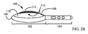
ここで図1、2A、2B及び2Cを参照する。これらは、一例に係る家庭用美容ボディコントワリング及びセルライトトリートメント装置の平面図及び側面図である。軽量ボディコントワリング及びセルライトトリートメント装置100は、ヘッド102及び保持容易なハンドル104を含む。ヘッド102は、円盤形状であり、又は他の適切な形状及び一般に平坦な断面を有する。代替的かつ随意的に、ヘッド102は断面が卵形(図2A)又は半卵形(図2B)であり、ハンドル104に一体的に取り付けられたベース106と、回転可能キャリア108を回転動作可能に収容する中心配置ボア302(図3)とを含む。ベース106は、電気回路及び配線のような様々な電気部品を収容する中空部である。
Reference is now made to FIGS. 1, 2A, 2B and 2C. These are a plan view and a side view of a household beauty body controlling and cellulite treatment device according to an example. The lightweight body controlling and
回転可能キャリア108はベース106内において、180度まで回転動作可能であり、又は時計回り方向若しくは反時計回り方向に揺動可能である。最も一般的なキャリア108は、矢印150に示すように揺動可能である。随意的に、キャリア108は、身体の輪郭に合わせて身体表面に均一な圧力を適用するべく、及び/又は、美容トリートメント対象の身体表面に振動エネルギーの形態にある機械エネルギーを適用するべく動作可能な受動型又は能動型の「浮動」キャリアである。これらは以下に詳述される。回転可能キャリア108の表面110は、曲面(図2A及び2B)又は平坦面(図2C)であり、一以上の剛体又は半剛体の曲線(例えばS字形状)RF電極112を含む。追加的かつ随意的に、表面110はまた、発光ダイオード(LED)、レーザ光源、強パルス光(IPL)、赤外(IR)エネルギー放射器等を含む光エネルギー放射器群から選択された一以上の発光素子114を含む。
図2A及び2Bに示されるように電極112は丸みのある断面を有し、表面110から1〜10mm突出する。丸みのある断面により、電極の尖った角及びエッジに沿って電荷及び電流が集中することでユーザに不快感を生じさせる一般的な現象を防止することができる。
As shown in FIGS. 2A and 2B, the
追加的に又は代替的かつ随意的に、ヘッド102は、ハンドル104又はベース106内のコントローラ120と通信する一以上のセンサ124を含む。センサ124は、キャリア108の表面110上に及び/又は一以上の電極112上に位置する。センサ124は、温度センサ、サーモパイル赤外線センサ、圧力センサ、光センサ、及び/又は動き若しくは位置センサを含むセンサ群から選択された一以上のセンサである。皮膚インピーダンスは電極112を介して検知することができる。
Additionally or alternatively and optionally, the
センサ124は、リム316(図3A及び3B)に沿って配列され、又は複数のRF電極112のまわり及び/又は間において表面110上に分散される。
追加的かつ随意的に、ヘッド102はまた、取り外し可能にベース106に取り付けられる剛体ヘッド102カバー122(図2A)も含む。
Additionally and optionally, the
ハンドル104は、充電可能バッテリ又は外部AC若しくはDC電源のような一以上の電源116、美容ボディコントワリング及びセルライトトリートメント装置100を起動させる起動ボタン118、RF電極112及び発光素子114を起動かつ制御するコントローラ120、電極112のようなヘッド102の電気部品を起動かつ制御する電子回路(図示せず)、一以上のモータ304(図3A)を含む。これらは以下に詳述される。
The
代替的かつ随意的に、電源116、起動ボタン118、コントローラ120、モータ304及び電子回路(図示せず)はヘッド102内に収容される。
Alternatively and optionally, the
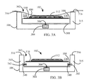
ここで図3A及び3Bを参照する。これらは、いくつかの例に係る家庭用美容ボディコントワリング及びセルライトトリートメント装置のヘッドを簡単に例示するQ−Q軸線(図1)断面図である。図3Aに示されるように、ベース106は、床308と、リム316を含んで回転可能キャリア108の収容動作が可能なリング状鉛直壁315とによって画定された中心配置ボア302を含む。いくつかの例では、リム316は丸みのあるエッジを有する。キャリア108は、剛体の、伸縮自在の又は可撓性の回転可能駆動器306を介して揺動電気モータ304に取り付けられる。モータ304は、ブラシレスモータ、AC若しくはDCモータ、ステッパモータ又は圧電モータを含むモータ群から選択され、ハンドル104に組み込まれた場合に機械伝動を介してキャリア108を駆動する。
Reference is now made to FIGS. 3A and 3B. These are QQ axis (FIG. 1) cross-sectional views that simply illustrate the heads of a home cosmetic body controlling and cellulite treatment device according to some examples. As shown in FIG. 3A, the
キャリア108は、壁315のリム316がキャリア108の表面110上方に1〜10mm延びることができるようにボア302の中に落とし込まれる。この構成により、壁315によって画定されるボア302の沈下部分320、すなわちリム316の高さにありかつ壁315及びキャリア108の表面110に直交する仮想平面がもたらされる。その結果、図3Aに示されるように、ヘッド102が組織表面400(図4)に適用される場合、壁315のリム316の半径によって画定される限られた面積の組織表面400(図3Aにおいて破線で示される)のみが、沈下部分320の中に入るように促されてキャリア108の表面110及び電極112に接触するようになる。キャリア108の表面110上に1〜10mm延びる壁315のリム316は、組織表面400(図3Aにおいて破線で示される)によって適用される圧力のほとんどを吸収し又は受け入れる。これゆえに、沈下部分320の中に入るように促されかつキャリア108の表面110及び電極112に接触する組織のセグメントは、モータ304の軸306に過剰な圧力を適用することがない。いくつかの例では軸306は伸縮自在軸である。
The
代替的かつ随意的に、キャリア108はまた、図3Bに示されるように、壁315の溝342の中を鉛直方向に摺動可能及び/又は回転可能な水平回転ホイール340も含む。これにより、キャリア108はボア302の内側の中心に維持される。
Alternatively and optionally, the
ここで図4A、4B及び4Cを参照する。これらは、2つの例に係るキャリアのマッサージ効果を描く簡単な例示のW−W軸線(図1)断面図である。 Reference is now made to FIGS. 4A, 4B and 4C. These are simple exemplary WW axis (FIG. 1) cross-sectional views depicting the massage effect of a carrier according to two examples.
図4Aに示されるように、キャリア108のマッサージ効果は、例えば偏心回転質量によって生じる。キャリア108の表面110の反対側表面に取り付けられた振動するコイン型等の電気モータ402が、当該質量を回転させるべく又はキャリア108を直接振動させるべく結合される。キャリア108は、キャリア108の揺動を許容するべく鉛直方向に伸縮動作可能な及び剪断力により部分的に変形可能な一以上のバイアス404上に載置される。
As shown in FIG. 4A, the massage effect of the
モータ402は、双方向矢印450によって描かれるように特に表面110に対して垂直方向の、又は双方向矢印470によって描かれるように表面110に対して平行方向の鉛直振動を誘導する。
The
追加的かつ随意的に、キャリア108には、可撓性駆動器406を介してキャリア108に接続されたモータ304による揺動がもたらされる。
Additionally and optionally, the
図4B及び4Cは、図3Aに描かれているのと同様の配列で揺動電気モータ304がキャリア108に取り付けられている他例を描く。キャリア108は、バイアス408内に収容された回転可能な伸縮自在駆動器306を介して駆動される。追加的に、キャリア108はまた、その周囲沿いが、キャリア108の限られた揺動を許容するべく動作可能な一以上の柔軟線410によって支持される。
4B and 4C depict another example in which an oscillating
図4Bにおいて、柔軟線410は静止した緩んだ位置に存在するように示される。キャリア108はバイアス408によってモータ304に向かって引っ張られる。ヘッド102が組織表面400に適用されるときにボア302の沈下部分320の中に入るように促される組織表面400が収容される。揺動する場合、図4Cに示されるように、キャリア108の部分的な回転によって、キャリア108を鉛直方向にかつモータ304から離して組織表面400に寄るように引っ張る柔軟線410の張力が増大する。組織表面400は、ボア302の沈下部分320から出るように強いられ、バイアス408には荷重がかかる。反対方向の回転は柔軟線410の緩みをもたらし、図4Bに示されるように、バイアス408は再びキャリア108をモータ304に向けて鉛直方向に引っ張る。ヘッド102が組織表面400に適用されるときにボア302の沈下部分320の中に入るように促される組織表面400が、再び収容される。このメカニズムは、キャリア108の揺動中、沈下部320の中に収容される組織表面400の限られた部分に対し及び当該部分に垂直に機械的なマッサージ効果を及ぼす。
In FIG. 4B, the
他例が図5A及び5Bに描かれる。これらは、2例に係る家庭用美容ボディコントワリング及びセルライトトリートメント装置のヘッドを簡単に例示するW−W軸線(図1)断面図である。キャリア108の表面110は曲げられてベース106のリム316を超えて延びる。図5Aが図4Aと類似の構成を描く一方、図5Bは図3Aと類似の構成を描く。キャリア108の表面110は剛体であるか、又は、身体の輪郭に対するヘッド102の適用の快適性を増大させる感触の柔軟体である。表面110が柔軟体の場合、電極112もまた、身体の輪郭に対するヘッド102の適用の快適性を増す半剛体となり得る。
Another example is depicted in FIGS. 5A and 5B. These are cross-sectional views taken along the W-W axis (FIG. 1) that simply illustrate the heads of home cosmetic body controlling and cellulite treatment devices according to two examples. The
図5Bにおいて、温度又は圧力センサのようなセンサ124が、単数又は複数のRF電極112上に位置決めされるように示される。随意的に、センサ124は、表面112に取り付けられた他方の電極112上の他のセンサ(図示せず)と対にされたインピーダンスセンサである。この構成では、RF電極112は、パルスRFエネルギーを組織表面400(図4)に適用してRFパルス同士間の組織インピーダンスを測定する。
In FIG. 5B, a
追加的かつ随意的に、キャリア108はまた、上述のような一以上の温度赤外センサを含む。
Additionally and optionally, the
ここで図6A、6B、6C及び6Dを参照する。これらは、一例に係る家庭用美容ボディコントワリング及びセルライトトリートメント装置の揺動ヘッド102(図1)の発光素子を簡単に例示する平面図である。図6Aに示されるように、発光素子114は、キャリア108の表面110上のRF電極112まわりに同心円状に配列されてRF電極112とともに揺動する。代替的かつ随意的に、図6Bに描かれるように発光素子114は、RF電極112まわりにベース106のリム316に沿って固定同心円パターンで配列される。図6Cは、キャリア108の表面110上における、図5A及び5Bに例示される発光素子114の配列を例示する。この例では、電極112は非S字形状曲線電極である。図6Dに示されるように、発光素子114は、キャリア108の表面110全体にかつ電極112同士の間に分散される。
Reference is now made to FIGS. 6A, 6B, 6C and 6D. These are plan views simply illustrating the light emitting elements of the swing head 102 (FIG. 1) of the home beauty body controlling and cellulite treatment device according to an example. As shown in FIG. 6A, the
一例に係る家庭用美容ボディコントワリング及びセルライトトリートメント装置を簡単に例示する平面図である図7は、単数のRF電極装置を例示する。この構成において、帰還電極702が、ハンドル104がユーザの手によって把持された場合にユーザの身体に接触するように、ハンドル104に埋め込まれ又は取り付けられる。
FIG. 7, which is a top view simply illustrating a home cosmetic body controlling and cellulite treatment device according to an example, illustrates a single RF electrode device. In this configuration, the
一例に係る家庭用美容ボディコントワリング及びセルライトトリートメント装置を簡単に例示する平面図である図8A及び8Bは、一般に使用される直線電極に対する曲線(例えばS字形状)電極の利点を実証する。一例では、用いられるS字形状電極112は、電極の尖った角及びエッジに沿って電荷及び電流が集中することでユーザに不快感を生じさせる一般的な現象を防止するべく、丸みのある断面及び丸みのある先端802を有する。
FIGS. 8A and 8B, which are top views briefly illustrating an example home cosmetic body controlling and cellulite treatment device, demonstrate the advantages of a curved (eg, S-shaped) electrode over a commonly used straight electrode. In one example, the
電極112の曲線形状によりユーザにとって、身体表面の所与面積に対し、直線電極812によっては適用できない一定量の美容トリートメントエネルギーを適用することが容易となる。図8A及び8Bにおいて、電極112及び812の長さはスケールどおりに描かれており同じである。
The curved shape of the
電極112/812を揺動させることによるトリートメントを受ける面積804を破線円で描く。当業者にわかるように、図8Aにおいて電極112は、その全長範囲に沿った面積804にエネルギーを適用することができるが、電極812(図8B)は、その長さの一部分のみに沿った面積804にエネルギーを適用することができるので、電極112は、家庭用装置にとって効率的、コンパクトかつ適切となる。さらに、以下で詳述されることだが、揺動するS字形状電極112が丸みのある前面806を含む場合、前面806は、複数の矢印850によって描かれるように、身体表面400(図4)に対して矢印750が示す方向に動かすときに、複数の矢印870によって描かれる電極812の直線状前面よりもユーザにとってずっと快適となる。
An
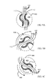
ここで図9A、9B及び9Cを参照する。これらは、一例に係る揺動曲線電極のマッサージ効果を簡単に例示する平面図である。図9A〜9Cでは例示のみを目的として、沈下部分320(図3A及び4B)の中に入るように促される組織表面400の一部分は、参照番号900で示す破線円によって描かれる。またも例示のみを目的として、図面では電極112のみが描かれる。図9Aに示されるように、ボディコントワリング及びセルライトトリートメント装置100は、身体表面400に適用されている。電極112同士間に組織が押し込まれて組織のひだ902がもたらされる。表面110(図1)の揺動により、最初に矢印950(図9B)が示す方向への電極112の部分的な回転が生じる。その後、矢印960(図9C)が示す反対方向への部分的な回転が生じる。電極112の揺動的な回転により、図9B及び9Cに示されるように、組織のひだ902の回転水平変位が生じる。これにより、表面400の下にある近似的に深さ1〜10mmまでの組織が変形かつマッサージされる。
Reference is now made to FIGS. 9A, 9B and 9C. These are plan views simply illustrating the massage effect of the swing curve electrode according to an example. 9A-9C, by way of example only, the portion of
図9A〜9Cに示されるように、沈下部分320の外側すなわち円900の外側における組織表面400の配向が、揺動サイクルの間中、直線配向に一般的に維持される。
As shown in FIGS. 9A-9C, the orientation of the
またも当業者にわかるように、本発明の装置は、以上において特に示され及び上述されたものに限られない。むしろ、本発明の範囲は、上述の説明を読む当業者に想到されかつ従来技術には存在しない修正例及び変形のみならず、上述された様々な特徴のコンビネーションと変更を加えたサブコンビネーションとの双方も含む。 As will also be appreciated by those skilled in the art, the apparatus of the present invention is not limited to what has been particularly shown and described above. Rather, the scope of the present invention is not limited to modifications and variations that have been conceived by those skilled in the art reading the above description and do not exist in the prior art, but also combinations of the various features described above and subcombinations with modifications. Includes both.
Claims (19)
一定軸まわりに時計回り方向及び反時計回り方向に回転可能な揺動キャリアを含むヘッドと、
前記ヘッドに一体的に取り付けられた保持容易なハンドルと、
前記揺動キャリアの表面上に設けられた少なくとも一つのRF電極と
を含み、
前記RF電極は、前記一定軸の方向から見てS字形状に構成されることにより、その全長範囲に沿った領域にエネルギーを適用する装置。 A home beauty body controlling device,
A head including an oscillating carrier rotatable in a clockwise direction and a counterclockwise direction around a fixed axis ;
An easy-to-hold handle integrally attached to the head;
See contains at least one of R F electrode is provided on a surface of the oscillating carrier,
The RF electrode is configured to be S-shaped when viewed from the direction of the constant axis, thereby applying energy to a region along the entire length range .
電源が充電可能バッテリ及び外部AC又はDC電源の少なくとも一つである請求項1に記載の装置。 In addition, it includes a power supply, start button, controller and electronic circuit,
The apparatus of claim 1, wherein the power source is at least one of a rechargeable battery and an external AC or DC power source.
前記ハンドルに一体的に取り付けられたベースと、
床とリムを有するリング状壁とによって画定されて前記揺動キャリアを、前記一定軸まわりに回転動作可能に収容する中心配置のボアと
を含む請求項1に記載の装置。 The head further includes
A base integrally attached to the handle;
2. The apparatus of claim 1 including a centrally located bore defined by a floor and a ring-shaped wall having a rim for receiving said oscillating carrier for rotation about said fixed axis .
前記揺動キャリアはさらに表面を含み、
センサが、前記リムに沿って配列され、又は複数のRF電極のまわり及び/若しくは間において前記揺動キャリアの前記表面上に分散される請求項1に記載の装置。 The head further includes a base having a centered bore defined by a floor and a ring-shaped wall having a rim;
The rocking carrier further includes a surface;
The apparatus according to claim 1, wherein sensors are arranged along the rim or distributed on the surface of the rocking carrier around and / or between a plurality of RF electrodes.
前記揺動電気モータは、ブラシレスモータ、AC若しくはDCモータ、ステッパモータ又は圧電モータを含むモータ群から選択される請求項5に記載の装置。 The swing carrier is attached via a shaft to a swing electric motor positioned on at least one of the base and the handle,
6. The apparatus of claim 5 , wherein the oscillating electric motor is selected from a motor group including a brushless motor, an AC or DC motor, a stepper motor, or a piezoelectric motor.
前記リング状壁のリムは、前記揺動キャリアの表面上方に1〜10mm延び、かつ、組織のセグメントを、前記ヘッドが前記組織の表面に適用されるときに収容するべく動作可能な前記ボアの沈下部分を画定し、前記組織の表面の限られた面積のみが前記沈下部分の中に入るように促されて前記揺動キャリアの表面及び前記RF電極に接触するようになる請求項5に記載の装置。 The rocking carrier is dropped into the bore;
The ring wall rim extends 1-10 mm above the surface of the rocking carrier and is operable to receive a tissue segment when the head is applied to the tissue surface. defining a subsidence part, according to claim 5 in which only a limited area of the surface of the tissue comes into contact with the surface and the RF electrodes of the oscillating carrier prompted to enter within said sink portion Equipment.
キャリアの表面に接触することはモータの軸へ過剰な圧力を適用することがない請求項10に記載の装置。 The rim of the ring-shaped wall absorbs most of the pressure applied by the tissue surface and the tissue urged to enter the subsidence,
11. The apparatus of claim 10 , wherein contacting the surface of the carrier does not apply excessive pressure to the motor shaft.
保持容易なハンドルと、
円盤形状を有するヘッドであって、前記ハンドルに一体的に取り付けられたベースと中心配置のボアとを含むヘッドと、
表面を有して前記ボア内を一定軸まわりに180度まで時計回り方向又は反時計回り方向に回転する動作が可能な、前記表面に取り付けられた少なくとも一つの剛体又は半剛体のRF電極を有する回転可能キャリアと、
前記表面に取り付けられた発光素子及びセンサと
を含み、
前記RF電極は、前記一定軸の方向から見てS字形状に構成されることにより、その全長範囲に沿った領域にエネルギーを適用する装置。 A home beauty body controlling device,
A handle that is easy to hold,
A head having a disk shape, a head including a bore centered arrangement and a base that is integrally attached to the said handle,
Surface capable of operating you rotating in a clockwise or counterclockwise direction up to 180 degrees around a fixed axis within said bore a, RF electrodes of the at least one rigid or semi-rigid attached to said surface A rotatable carrier having
Look including a light emitting element and a sensor mounted on said surface,
The RF electrode is configured to be S-shaped when viewed from the direction of the constant axis, thereby applying energy to a region along the entire length range .
14. A device according to claim 1 or 13 , wherein the cross section of the head along the constant axis is oval or semi-oval.
Applications Claiming Priority (2)
| Application Number | Priority Date | Filing Date | Title |
|---|---|---|---|
| US201261675973P | 2012-07-26 | 2012-07-26 | |
| PCT/IL2013/000061 WO2014016820A2 (en) | 2012-07-26 | 2013-07-22 | A home-use cosmetic treatment device |
Publications (3)
| Publication Number | Publication Date |
|---|---|
| JP2015531245A JP2015531245A (en) | 2015-11-02 |
| JP2015531245A5 JP2015531245A5 (en) | 2016-09-08 |
| JP6208758B2 true JP6208758B2 (en) | 2017-10-18 |
Family
ID=49997922
Family Applications (1)
| Application Number | Title | Priority Date | Filing Date |
|---|---|---|---|
| JP2015523655A Expired - Fee Related JP6208758B2 (en) | 2012-07-26 | 2013-07-22 | Household beauty treatment equipment |
Country Status (5)
| Country | Link |
|---|---|
| US (1) | US20150224020A1 (en) |
| EP (1) | EP2877244A4 (en) |
| JP (1) | JP6208758B2 (en) |
| IL (1) | IL236720A0 (en) |
| WO (1) | WO2014016820A2 (en) |
Families Citing this family (27)
| Publication number | Priority date | Publication date | Assignee | Title |
|---|---|---|---|---|
| DE102012013534B3 (en) | 2012-07-05 | 2013-09-19 | Tobias Sokolowski | Apparatus for repetitive nerve stimulation for the degradation of adipose tissue by means of inductive magnetic fields |
| US11491342B2 (en) | 2015-07-01 | 2022-11-08 | Btl Medical Solutions A.S. | Magnetic stimulation methods and devices for therapeutic treatments |
| US20180001107A1 (en) | 2016-07-01 | 2018-01-04 | Btl Holdings Limited | Aesthetic method of biological structure treatment by magnetic field |
| US10695575B1 (en) | 2016-05-10 | 2020-06-30 | Btl Medical Technologies S.R.O. | Aesthetic method of biological structure treatment by magnetic field |
| US11266850B2 (en) | 2015-07-01 | 2022-03-08 | Btl Healthcare Technologies A.S. | High power time varying magnetic field therapy |
| US11484724B2 (en) | 2015-09-30 | 2022-11-01 | Btl Medical Solutions A.S. | Methods and devices for tissue treatment using mechanical stimulation and electromagnetic field |
| CN105251108B (en) * | 2015-10-24 | 2019-04-19 | 王芬秀 | A kind of skin care device |
| US11253717B2 (en) | 2015-10-29 | 2022-02-22 | Btl Healthcare Technologies A.S. | Aesthetic method of biological structure treatment by magnetic field |
| US11464993B2 (en) | 2016-05-03 | 2022-10-11 | Btl Healthcare Technologies A.S. | Device including RF source of energy and vacuum system |
| US11247039B2 (en) | 2016-05-03 | 2022-02-15 | Btl Healthcare Technologies A.S. | Device including RF source of energy and vacuum system |
| US11534619B2 (en) | 2016-05-10 | 2022-12-27 | Btl Medical Solutions A.S. | Aesthetic method of biological structure treatment by magnetic field |
| US10583287B2 (en) | 2016-05-23 | 2020-03-10 | Btl Medical Technologies S.R.O. | Systems and methods for tissue treatment |
| CN105879225A (en) * | 2016-06-08 | 2016-08-24 | 广州加佳康医疗科技有限公司 | Intelligent and portable electrotherapeutical apparatus |
| US10556122B1 (en) | 2016-07-01 | 2020-02-11 | Btl Medical Technologies S.R.O. | Aesthetic method of biological structure treatment by magnetic field |
| US20180185236A1 (en) * | 2017-01-05 | 2018-07-05 | Benzion Levi | Multifunctional facial and body treatment device |
| US11399624B2 (en) * | 2018-12-18 | 2022-08-02 | L'oreal | Skincare device having optimized dual energy modalities, and associated systems and methods |
| US11730668B2 (en) | 2020-06-29 | 2023-08-22 | Therabody, Inc. | Vibrating therapy system and device |
| US10525277B1 (en) | 2019-01-08 | 2020-01-07 | Laluer Llc | Skin treatment device |
| PL4066887T3 (en) | 2019-04-11 | 2024-03-04 | Btl Medical Solutions A.S. | Devices for aesthetic treatment of biological structures by radiofrequency and magnetic energy |
| US11878167B2 (en) | 2020-05-04 | 2024-01-23 | Btl Healthcare Technologies A.S. | Device and method for unattended treatment of a patient |
| KR20230000081U (en) | 2020-05-04 | 2023-01-10 | 비티엘 헬쓰케어 테크놀로지스 에이.에스. | Device and method for unattended treatment of patients |
| US11564863B2 (en) | 2020-06-29 | 2023-01-31 | Therabody, Inc. | Cooling attachment module for facial treatment device |
| WO2022006086A1 (en) | 2020-06-29 | 2022-01-06 | Theragun, Inc. | Vibration therapy system and device |
| KR102304110B1 (en) * | 2021-01-29 | 2021-09-23 | (주)울파인 | Ultrasonic massager |
| USD1004793S1 (en) | 2021-03-02 | 2023-11-14 | Therabody, Inc. | Facial treatment device |
| USD976431S1 (en) | 2021-03-02 | 2023-01-24 | Therabody, Inc. | Facial treatment device |
| US11896816B2 (en) | 2021-11-03 | 2024-02-13 | Btl Healthcare Technologies A.S. | Device and method for unattended treatment of a patient |
Family Cites Families (12)
| Publication number | Priority date | Publication date | Assignee | Title |
|---|---|---|---|---|
| FR2738155B1 (en) * | 1995-08-31 | 1998-02-20 | Dervieux Dominique | DEVICE FOR THE RELIEF OF PAIN, CONTRACTURES AND OTHER REFLEX AND DERMATOLOGICAL ACTIONS BY APPLICATION OF ELECTRIC PULSES |
| JP3168162B2 (en) * | 1996-08-26 | 2001-05-21 | ヤーマン株式会社 | Complex beauty treatment equipment |
| US20070038206A1 (en) * | 2004-12-09 | 2007-02-15 | Palomar Medical Technologies, Inc. | Photocosmetic device |
| ES2432140T3 (en) * | 2004-08-06 | 2013-11-29 | Syneron Beauty Ltd. | Therapy device |
| US20080183252A1 (en) * | 2006-09-05 | 2008-07-31 | Roee Khen | Apparatus and method for treating cellulite |
| US9101524B2 (en) * | 2006-11-09 | 2015-08-11 | Lumenis Ltd. | Apparatus and method for treating tissue |
| AU2009215265A1 (en) * | 2008-02-20 | 2009-08-27 | Syneron Medical Ltd. | A skin treatment apparatus for personal use and method for using same |
| EP2258332B1 (en) * | 2009-06-03 | 2012-02-15 | Yongxing Yan | Massage device |
| US8500754B2 (en) * | 2010-04-30 | 2013-08-06 | Johnson & Johnson Consumer Companies, Inc. | Handheld, personal skin care systems with detachable skin care elements |
| JP5934211B2 (en) * | 2010-08-19 | 2016-06-15 | シネロン メディカル リミテッド | Electromagnetic energy applicator for personal cosmetic skin treatment |
| EP2637625A4 (en) * | 2010-11-12 | 2015-03-04 | Syneron Medical Ltd | Method and device for soft tissue treatment |
| JP2013078432A (en) * | 2011-10-03 | 2013-05-02 | Panasonic Corp | Cosmetic device |
-
2013
- 2013-07-22 US US14/417,556 patent/US20150224020A1/en not_active Abandoned
- 2013-07-22 JP JP2015523655A patent/JP6208758B2/en not_active Expired - Fee Related
- 2013-07-22 WO PCT/IL2013/000061 patent/WO2014016820A2/en active Application Filing
- 2013-07-22 EP EP13822583.4A patent/EP2877244A4/en not_active Withdrawn
-
2015
- 2015-01-15 IL IL236720A patent/IL236720A0/en unknown
Also Published As
| Publication number | Publication date |
|---|---|
| IL236720A0 (en) | 2015-02-26 |
| US20150224020A1 (en) | 2015-08-13 |
| EP2877244A2 (en) | 2015-06-03 |
| EP2877244A4 (en) | 2016-07-13 |
| WO2014016820A2 (en) | 2014-01-30 |
| JP2015531245A (en) | 2015-11-02 |
| WO2014016820A3 (en) | 2015-06-25 |
Similar Documents
| Publication | Publication Date | Title |
|---|---|---|
| JP6208758B2 (en) | Household beauty treatment equipment | |
| US10966515B2 (en) | Skincare device | |
| KR102321046B1 (en) | Massage device with massage head provided with tapping finger | |
| US10383486B2 (en) | Handheld motorized facial brush having three floating heads | |
| CN112956934B (en) | Skin cleaner | |
| KR102307741B1 (en) | Massage device with at least one massage head having eccentric rotation | |
| KR20200013653A (en) | TENS attachment for device to clean and treat skin | |
| JP2015531245A5 (en) | ||
| JP5916362B2 (en) | Facial massager | |
| JP2009525066A (en) | Skin cleaner | |
| KR20160072194A (en) | Massage device with massage head provided with a paddle roller and a smooth roller | |
| KR20160068781A (en) | Hand held dermaplaning device and dermaplaning process | |
| US6997889B1 (en) | Electric massage comb | |
| WO2019173652A1 (en) | Devices and systems for manipulating tissue and methods for using same | |
| KR20180123662A (en) | Fragment type derma planing device and derma planing process | |
| US20170119618A1 (en) | Lower eyelid treatment | |
| KR101747949B1 (en) | Skin Beauty Machine for Massage and Control Method Thereof | |
| KR102507843B1 (en) | Device for skin care | |
| JP6346015B2 (en) | Scalp / Skin Massager | |
| US20230172799A1 (en) | System and method for performing tissue treatment using powered treatment devices | |
| KR102370845B1 (en) | Multi-function skin care device | |
| CN209123189U (en) | Massage device | |
| JP6969028B1 (en) | Massage device | |
| KR101205959B1 (en) | Massage apparatus using spheroid wavelength | |
| TWM312982U (en) | Cosmetic equipment |
Legal Events
| Date | Code | Title | Description |
|---|---|---|---|
| A521 | Request for written amendment filed |
Free format text: JAPANESE INTERMEDIATE CODE: A523 Effective date: 20160721 |
|
| A621 | Written request for application examination |
Free format text: JAPANESE INTERMEDIATE CODE: A621 Effective date: 20160721 |
|
| A977 | Report on retrieval |
Free format text: JAPANESE INTERMEDIATE CODE: A971007 Effective date: 20170512 |
|
| A131 | Notification of reasons for refusal |
Free format text: JAPANESE INTERMEDIATE CODE: A131 Effective date: 20170704 |
|
| A521 | Request for written amendment filed |
Free format text: JAPANESE INTERMEDIATE CODE: A523 Effective date: 20170727 |
|
| TRDD | Decision of grant or rejection written | ||
| A01 | Written decision to grant a patent or to grant a registration (utility model) |
Free format text: JAPANESE INTERMEDIATE CODE: A01 Effective date: 20170808 |
|
| A61 | First payment of annual fees (during grant procedure) |
Free format text: JAPANESE INTERMEDIATE CODE: A61 Effective date: 20170907 |
|
| R150 | Certificate of patent or registration of utility model |
Ref document number: 6208758 Country of ref document: JP Free format text: JAPANESE INTERMEDIATE CODE: R150 |
|
| LAPS | Cancellation because of no payment of annual fees |