JP6206503B2 - Imaging device - Google Patents
Imaging device Download PDFInfo
- Publication number
- JP6206503B2 JP6206503B2 JP2015546602A JP2015546602A JP6206503B2 JP 6206503 B2 JP6206503 B2 JP 6206503B2 JP 2015546602 A JP2015546602 A JP 2015546602A JP 2015546602 A JP2015546602 A JP 2015546602A JP 6206503 B2 JP6206503 B2 JP 6206503B2
- Authority
- JP
- Japan
- Prior art keywords
- lens
- imaging
- lens hood
- recess
- hood
- Prior art date
- Legal status (The legal status is an assumption and is not a legal conclusion. Google has not performed a legal analysis and makes no representation as to the accuracy of the status listed.)
- Active
Links
Images


Classifications
-
- G—PHYSICS
- G03—PHOTOGRAPHY; CINEMATOGRAPHY; ANALOGOUS TECHNIQUES USING WAVES OTHER THAN OPTICAL WAVES; ELECTROGRAPHY; HOLOGRAPHY
- G03B—APPARATUS OR ARRANGEMENTS FOR TAKING PHOTOGRAPHS OR FOR PROJECTING OR VIEWING THEM; APPARATUS OR ARRANGEMENTS EMPLOYING ANALOGOUS TECHNIQUES USING WAVES OTHER THAN OPTICAL WAVES; ACCESSORIES THEREFOR
- G03B11/00—Filters or other obturators specially adapted for photographic purposes
- G03B11/04—Hoods or caps for eliminating unwanted light from lenses, viewfinders or focusing aids
-
- H—ELECTRICITY
- H04—ELECTRIC COMMUNICATION TECHNIQUE
- H04N—PICTORIAL COMMUNICATION, e.g. TELEVISION
- H04N23/00—Cameras or camera modules comprising electronic image sensors; Control thereof
- H04N23/50—Constructional details
- H04N23/55—Optical parts specially adapted for electronic image sensors; Mounting thereof
-
- G—PHYSICS
- G02—OPTICS
- G02B—OPTICAL ELEMENTS, SYSTEMS OR APPARATUS
- G02B7/00—Mountings, adjusting means, or light-tight connections, for optical elements
- G02B7/02—Mountings, adjusting means, or light-tight connections, for optical elements for lenses
-
- G—PHYSICS
- G03—PHOTOGRAPHY; CINEMATOGRAPHY; ANALOGOUS TECHNIQUES USING WAVES OTHER THAN OPTICAL WAVES; ELECTROGRAPHY; HOLOGRAPHY
- G03B—APPARATUS OR ARRANGEMENTS FOR TAKING PHOTOGRAPHS OR FOR PROJECTING OR VIEWING THEM; APPARATUS OR ARRANGEMENTS EMPLOYING ANALOGOUS TECHNIQUES USING WAVES OTHER THAN OPTICAL WAVES; ACCESSORIES THEREFOR
- G03B11/00—Filters or other obturators specially adapted for photographic purposes
- G03B11/04—Hoods or caps for eliminating unwanted light from lenses, viewfinders or focusing aids
- G03B11/045—Lens hoods or shields
-
- G—PHYSICS
- G03—PHOTOGRAPHY; CINEMATOGRAPHY; ANALOGOUS TECHNIQUES USING WAVES OTHER THAN OPTICAL WAVES; ELECTROGRAPHY; HOLOGRAPHY
- G03B—APPARATUS OR ARRANGEMENTS FOR TAKING PHOTOGRAPHS OR FOR PROJECTING OR VIEWING THEM; APPARATUS OR ARRANGEMENTS EMPLOYING ANALOGOUS TECHNIQUES USING WAVES OTHER THAN OPTICAL WAVES; ACCESSORIES THEREFOR
- G03B17/00—Details of cameras or camera bodies; Accessories therefor
- G03B17/02—Bodies
-
- H—ELECTRICITY
- H04—ELECTRIC COMMUNICATION TECHNIQUE
- H04N—PICTORIAL COMMUNICATION, e.g. TELEVISION
- H04N23/00—Cameras or camera modules comprising electronic image sensors; Control thereof
- H04N23/50—Constructional details
- H04N23/51—Housings
-
- H—ELECTRICITY
- H04—ELECTRIC COMMUNICATION TECHNIQUE
- H04N—PICTORIAL COMMUNICATION, e.g. TELEVISION
- H04N23/00—Cameras or camera modules comprising electronic image sensors; Control thereof
- H04N23/50—Constructional details
- H04N23/54—Mounting of pick-up tubes, electronic image sensors, deviation or focusing coils
-
- H—ELECTRICITY
- H04—ELECTRIC COMMUNICATION TECHNIQUE
- H04N—PICTORIAL COMMUNICATION, e.g. TELEVISION
- H04N7/00—Television systems
- H04N7/14—Systems for two-way working
- H04N7/141—Systems for two-way working between two video terminals, e.g. videophone
- H04N7/142—Constructional details of the terminal equipment, e.g. arrangements of the camera and the display
-
- H—ELECTRICITY
- H04—ELECTRIC COMMUNICATION TECHNIQUE
- H04N—PICTORIAL COMMUNICATION, e.g. TELEVISION
- H04N7/00—Television systems
- H04N7/14—Systems for two-way working
- H04N7/15—Conference systems
Description
本発明は、レンズを保護する機構を備えた撮像装置に関する。 The present invention relates to an imaging device having a mechanism for protecting a lens.
インターネット等の通信ネットワークを介して遠隔地との間で、遠隔会議を行う会議システムが普及している。この会議システムに関し、会議出席者がいる一方の会議室において、通信装置により、会議出席者の画像及び発言などの音声を撮影及び収集したものをデジタルデータに変換して相手方の通信装置に送信する。そして、撮影画像を表示、収集した音声を相手方の会議室において出力することにより、実際の会議に近い状態で遠隔会議を行う技術が知られている。 2. Description of the Related Art Conference systems that conduct remote conferences with remote locations via a communication network such as the Internet are widespread. With regard to this conference system, in a conference room where a conference attendee is present, a communication device captures and collects voices such as images and speeches of conference attendees, converts them into digital data, and transmits the digital data to the other communication device. . And the technique of performing a remote conference in the state close | similar to an actual meeting is known by displaying the picked-up image and outputting the collected audio | voice in the other party's meeting room.
上記に関し、特許文献1には携帯性に優れる通信装置を提供することを目的として、電子カメラを含む画像入力ユニットと筐体とを回動可能に接続する一軸ヒンジを備えた構造が記載されている。 With respect to the above, Patent Document 1 describes a structure including a uniaxial hinge that rotatably connects an image input unit including an electronic camera and a housing for the purpose of providing a communication device having excellent portability. Yes.
特許文献1に記載された技術によれば、通信装置の携帯性を高め、カメラアームを収納することでレンズの保護が可能なため、従来付属していたレンズキャップが不要となり、使用あるいは未使用時にレンズキャップを着脱するという煩雑な作業が不要となる。また、特許文献1では、カメラアーム収納時にレンズが筐体に対して接触しないように、突起部とレンズフィルタとを備えている。 According to the technique described in Patent Document 1, the portability of the communication device is improved and the lens can be protected by storing the camera arm. Sometimes the cumbersome work of attaching and detaching the lens cap is unnecessary. In Patent Document 1, a projection and a lens filter are provided so that the lens does not come into contact with the housing when the camera arm is housed.
本発明の一実施例は、煩雑な操作や複雑な機構を要することなくレンズ保護を行うとともに、不要光による撮影画像の画質低下を防止することを目的とする。 An embodiment of the present invention aims to protect a lens without requiring a complicated operation and a complicated mechanism, and to prevent deterioration in image quality of a captured image due to unnecessary light.
本発明の一実施例による撮像装置は、被写体を撮像する撮像部と、前記撮像部を一端で保持する保持部と、前記撮像部と前記保持部とからなる撮像ユニットを収納する凹部が一側の面に形成された筐体と、前記凹部内で前記一側の面に略平行に延びる軸線の周りに相対回動可能に連結されたヒンジ部材を含み、前記ヒンジ部材が前記凹部内に収納された状態で該筐体に接続されたヒンジ装置と、を備える。前記撮像ユニットは、前記筐体に対し前記ヒンジ装置を介して前記軸線の周りで前記凹部内に収納される収納位置と前記凹部内から突出する突出位置との間を回動する。前記撮像部は、略長方形状の撮像素子と、前記撮像素子に外部からの光を入射させるレンズと、前記レンズの外周に設けられた略長方形状のレンズフードを備える。前記レンズフードは、少なくとも、前記撮像部により被写体を撮像するために必要な前記レンズから前記撮像素子に入射させる必要光を確保でき、前記レンズから前記撮像素子へ入射する不要光を遮光する遮光機能を確保できる距離だけ前記レンズ表面の頂点から突出している。前記レンズフードは、前記レンズフードと前記レンズとが嵌合された状態で前記レンズの表面を露出させる開口部を有し、前記開口部の外周に少なくとも3つの突起が相互に等間隔に配置されている。 An imaging apparatus according to an embodiment of the present invention includes an imaging unit that captures an image of a subject, a holding unit that holds the imaging unit at one end, and a recess that houses an imaging unit including the imaging unit and the holding unit. And a hinge member connected to the inside of the recess so as to be relatively rotatable about an axis extending substantially parallel to the one side surface. The hinge member is housed in the recess. And a hinge device connected to the housing in a state of being provided. The imaging unit rotates with respect to the housing between a storage position stored in the recess and a protruding position protruding from the recess around the axis via the hinge device. The imaging unit includes a substantially rectangular imaging element, a lens for allowing light from the outside to enter the imaging element, and a substantially rectangular lens hood provided on the outer periphery of the lens. The lens hood can secure at least necessary light to be incident on the imaging element from the lens necessary for imaging the subject by the imaging unit, and shields unnecessary light incident on the imaging element from the lens. Projecting from the apex of the lens surface by a distance that can ensure the above. The lens hood has an opening that exposes the surface of the lens in a state where the lens hood and the lens are fitted, and at least three protrusions are arranged at equal intervals on the outer periphery of the opening. ing.
本発明の一実施例によれば、煩雑な操作や複雑な機構を要することなくレンズ保護を行うとともに、不要光による撮影画像の画質低下を防止することが可能となる。 According to an embodiment of the present invention, it is possible to protect a lens without requiring a complicated operation and a complicated mechanism, and to prevent a deterioration in image quality of a captured image due to unnecessary light.
本発明の実施形態の撮像装置に関し以下図面を用いて説明するが、本発明の趣旨を越えない限り、何ら本実施形態に限定されるものではない。なお、各図中、同一又は相当する部分には同一の符号を付しており、その重複説明は適宜に簡略化乃至省略する。
以下の説明では、本実施形態における撮像装置を備える装置として図1及び図2に示したテレビ会議装置を一例に説明するが、本発明はテレビ会議装置に限定されるものでなく、ビデオカメラ、スチルカメラ、テレビ会議装置等の通信装置やスマートフォン等の情報処理装置、その他撮像部が本体筐体に収納されるタイプの撮像装置、通信装置や情報処理装置等に適用されるものであってもよい。An imaging apparatus according to an embodiment of the present invention will be described below with reference to the drawings. However, the present invention is not limited to this embodiment as long as the gist of the present invention is not exceeded. In addition, in each figure, the same code | symbol is attached | subjected to the part which is the same or it corresponds, The duplication description is simplified thru | or abbreviate | omitted suitably.
In the following description, the video conference device shown in FIGS. 1 and 2 will be described as an example of a device including the imaging device in the present embodiment, but the present invention is not limited to the video conference device, and a video camera, Even a communication device such as a still camera or a video conference device, an information processing device such as a smartphone, or any other imaging device in which the imaging unit is housed in the main body housing, a communication device or an information processing device, etc. Good.
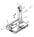
本発明の実施形態における撮像装置を備える装置としてのテレビ会議装置1の概略構成について図1及び図2を参照して説明する。図1は、テレビ会議装置1の不使用状態における外観を示したものである。テレビ会議装置1は、不使用状態において、全体として、薄く細長い略直方体状あるいは略平板状の外形を有している。テレビ会議装置1は、例えば机、テーブル上などに水平面に平行に載置されている。 A schematic configuration of a video conference device 1 as a device including an imaging device according to an embodiment of the present invention will be described with reference to FIGS. 1 and 2. FIG. 1 shows an external appearance of the video conference apparatus 1 when not in use. When not in use, the video conference apparatus 1 has a thin, thin, substantially rectangular parallelepiped or substantially flat outer shape as a whole. The video conference device 1 is placed, for example, on a desk or table parallel to the horizontal plane.
テレビ会議装置1は、カメラヘッド21とカメラアーム22からなる撮像ユニットとしてのカメラ部20と、筐体30で構成される。カメラヘッド21は被写体を撮像する撮像部であり、カメラアーム22はカメラヘッド21を一端で保持する保持部である。筐体30には、カメラ部20を収納する凹部31が一側の面としての筐体30の上面に形成されている。図1に示すように、カメラ部20は使用されないとき凹部31に収納される。これによりテレビ会議装置1は持ち運びしやすくなり携帯性が向上する。このカメラ部20が、撮像装置に該当する。
The video conference apparatus 1 includes a
次に、テレビ会議装置1の使用時の状態について図2を加えて説明する。ここで、テレビ会議装置1は、凹部31内で上面に略平行に延びる軸線の周りに相対回動可能に連結されたヒンジ部材が凹部31内に収納された状態で筐体30に接続されたヒンジ装置Hを備える。カメラ部20を使用する際は、ヒンジ装置Hの回動軸を介してカメラ部20を筐体30に対して垂直する位置まで回動方向Rへ回動させる。
Next, a state when the video conference apparatus 1 is used will be described with reference to FIG. Here, the video conference apparatus 1 is connected to the
より具体的にカメラ部20の回動機構について説明する。カメラ部20は、筐体30に対しヒンジ装置Hを介して軸線の周りで凹部31内に収納される収納位置Sと凹部31内から突出する突出位置Tとの間を回動する。
More specifically, the rotation mechanism of the
本実施形態のテレビ会議装置1は、使用時にはカメラ部20を収納位置Sから突出位置Tへ回動させることで、カメラヘッド21の高さとユーザーの目線が一致する。このため、カメラ部20から所定の投影部へ映し出された映像にユーザーの視線が一致し、ユーザーは映し出された映像を無理なく見ることができる。
The video conference apparatus 1 of the present embodiment rotates the
カメラ部20の使用時、カメラ部20は筐体30から垂直に突出するため、このまま持ち運ぶには不便である。しかし、本実施形態のように、凹部31にカメラ部20を収納位置Sへ収納することで持ち運びやすくなり携帯性が向上する。
When the
本実施形態の構造上の特徴としては、上述の点に加え、カメラ部20を筐体30に収納したときのカメラ部20が備えるレンズ部分を外部からの衝撃や汚れから保護し、収納される筐体30の当接面とレンズ部分との接触による損傷を防ぐレンズフードを備える点である。
As structural features of the present embodiment, in addition to the above-described points, the lens portion of the
ここで、例えば、一般的な一眼レフカメラやビデオカメラのように、カメラレンズに単にレンズフードが装着されているだけの構成では、レンズフードが収納時における破損を防止する役割を担ってはいない。つまり、一般的な一眼レフカメラやビデオカメラの収納時には、レンズカバーを利用することで、レンズへの埃などの汚れの付着やレンズ表面に傷がつくのを防いでいる。つまり、レンズフードとは別体のレンズカバーが必要である。 Here, for example, in a configuration in which a lens hood is simply attached to a camera lens, such as a general single-lens reflex camera or a video camera, the lens hood does not play a role in preventing damage during storage. . In other words, when a general single-lens reflex camera or video camera is housed, the lens cover is used to prevent dirt and other dirt from being attached to the lens and damage to the lens surface. That is, a lens cover separate from the lens hood is required.
また、カメラ部20を凹部31に収納する際に、レンズフードが無ければ、筐体30にレンズが接触することになる。例えば、カメラアーム22をユーザーが勢いよく倒した際には、レンズと筐体30が強く接触し、衝撃によりレンズが損傷する恐れがある。
Further, when the
他方、レンズ周りに突起物を設けることにより、レンズの保護を行うことも可能である。しかし、突起物の形状によっては、レンズへの入射光が遮られ、撮影した画像に物理的な影が写ってしまう所謂ケラレ現象が生じる可能性もある。このため、レンズを保護するための単純な突起物を設けるだけでは画質の向上を図ることができない。 On the other hand, it is also possible to protect the lens by providing a protrusion around the lens. However, depending on the shape of the protrusion, there is a possibility that a so-called vignetting phenomenon occurs in which the incident light to the lens is blocked and a physical shadow appears in the photographed image. For this reason, the image quality cannot be improved only by providing a simple protrusion for protecting the lens.
本実施形態は、上述したようなカメラアーム22の回動機構に加えて後述する特徴的なレンズフードを採用する。これにより、煩雑な操作や複雑な機構を要することなくレンズ保護を行うとともに、不要光による撮影画像の画質低下を防止することができることを特徴とするものである。なお、本実施形態によれば、使用時にカメラアームを立ち上げるという構造をとることにより、通常のカメラ等におけるレンズキャップを外すという操作を実現する。つまり、レンズキャップを外す操作を省略できるという効果がある。
The present embodiment employs a characteristic lens hood described later in addition to the rotation mechanism of the
本実施形態のレンズフード11を備えたカメラヘッド21の概略構成について図3〜9を参照して説明する。本実施形態のカメラヘッド21は、内部に略長方形状、例えば横縦比が16:9の撮像素子と、撮像素子に外部からの光を入射させるレンズ12と、レンズ12の外周に設けられた略長方形状、つまり矩形形状のレンズフード11を備える。このように、略長方形状は、撮像素子の形状とほぼ相似となっていると、レンズフードの高さが縦並びに横方向が一致するようになる。つまり、撮像素子への入射光を考慮しても、レンズフードの縦と横方向の高さが一致することになる。このためレンズフードの形成が容易となり、さらに、凹部31にカメラ部20を収納位置Sへ収納する際に、凹部31の形状を平面にすることが可能となる。凹部31をレンズフードの形状に合わせて成形することも可能であるが、製造時に複雑になる等の好ましくない状況が生ずる。
A schematic configuration of the
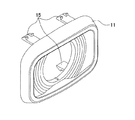
図3はカメラヘッド21の外観を示した斜視図である。レンズフード11は、カメラヘッド筐体13の端部でレンズ12部分の外周縁を覆うように設けられる。
FIG. 3 is a perspective view showing the appearance of the
レンズフード11の内側には、レンズフード11の被写体側の端面周囲から、該端面より撮像素子側に配置されるレンズフード11の開口部周囲に向けて傾斜状に形成された傾斜部14が設けられる。本実施形態では、例えば傾斜部14は階段状に形成されている(図3〜図6参照)。これによりレンズフード内での反射光がレンズ12に入射する割合を低減することができる。
On the inner side of the
なお、より一層光の反射を抑えるべく、レンズフード11に黒色を施すことが望ましい。
In order to further suppress the reflection of light, it is desirable to black the
また、図4に示すように、レンズフード11とレンズ12とが嵌合された状態でレンズ12の表面を露出させるレンズフード11の開口部Kの外周に少なくとも3つの突起110を相互に等間隔に配置している。
Further, as shown in FIG. 4, at least three
なお、突起110が無い場合には、レンズ12がレンズフード11の中心部に対して偏って位置する可能性があり、撮像素子への入射光が遮られる可能性がある。また、レンズフード11とレンズ12との間の隙間が視覚的に目立ってしまう。そこでレンズフード11の開口部Kの外周に少なくとも3つの突起110を相互に等間隔に配置する構成により、レンズ12をレンズフード11の中心部に位置させ、撮像素子への入射光を十分にし、レンズフード11とレンズ12間の隙間を目立たせない効果がある。
In addition, when there is no
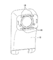
図6、図7、図8に示すように、レンズフード11の裏面には、レンズフード11をカメラヘッド筐体13に取り付ける取付手段としての爪部15を上下に2箇所ずつ計4箇所に、爪が設けられた側が外側になるように対向して設けられている。そして、この爪部15が、図9に示すカメラヘッド筐体13の対応する爪受け部16に嵌め合わされることにより、レンズフード11がカメラヘッド筐体13に取り付けられる。
As shown in FIGS. 6, 7, and 8, on the back surface of the
なお、レンズフード11の内側にゴムやスポンジ等の弾性材料を設けることにより、上述のような位置決めと、隙間を覆うような形状としても良い。
In addition, it is good also as a shape which covers the clearance gap as mentioned above by providing elastic materials, such as rubber | gum and sponge, inside the
また、レンズフード11をクッション材等の弾性部材により形成してもよい。さらに、筐体30の凹部31における、少なくともカメラ部20が収納位置Sに収納される場合の収納位置Sのカメラヘッド21に対向する部分をクッション材等の弾性部材により形成してもよい。これにより、カメラヘッド21やレンズ12への衝撃吸収効果を高めることができる。
Further, the
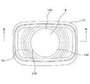
また、図8に示すように、本実施形態では、レンズフード11の被写体側の端面の少なくとも中央部113を該中央部113を挟んで両側に位置する端部に対して被写体側に突出させている。これは、例えば、レンズフード11の長手方向における端面111の中央部113が、レンズフード11の端面111の左右の両端部112に対してなだらかに突出して形成されていることを意味するものである。ここで端面111は、略長方形状の端面における一辺の部分を意味している。
Further, as shown in FIG. 8, in the present embodiment, at least the
より具体的には、中央部113に接する接線Yと、左右両端部112を結ぶ線分Zとの高さの差が1.0mm程度となるように中央部113が左右両端部112より突出していればよい。これによりカメラ部20を筐体30の凹部31に収納する際、レンズフード11が凹部31側に接触する位置が中央部113に限定される。なお、高さの差を1.0mm程度にしているのは、先にも示したように凹部31を深く形成しないためである。凹部31を深く形成することは、筐体の厚みを増加させることにつながるので、好ましくない。なお、中央部113ではなく、端部の一部が他の部分に対して突出していれば良いことは言うまでも無い。また、レンズフード11の上側の長手方向における端面と、下側の長手方向における端面の両方ともの中央部113が、両端部に対して突出していても良い。
More specifically, the
仮にレンズフード11の端面が平面状に形成されていると、筐体30に収納した際に、筐体30の対応部分と接触することによりレンズフード11全体に細かい傷が生じる結果となり、見た目を損なう。本実施形態の上述の構成によれば、筐体30との接触によりレンズフード11に生じる傷が特定の位置に限られるため、傷が目立たず、意匠性が向上するという効果がある。
If the end face of the
なお、本構成を採用する一方で、上述した凹部31側のカメラヘッド21に対向する部分を弾性部材により形成せずともよい。
While adopting this configuration, the portion facing the
次に、本実施形態におけるレンズフード11の構造の特徴的構成について図10及び図11を参照して説明する。まず、本実施形態のテレビ会議装置1においては、会議参加者を撮影視野に納められるように、広角カメラを用いることが望ましい。一般的に、広角カメラを採用した場合、広範囲に亘って光線を撮像素子に入射させる必要があるため、レンズフードの全長、つまりレンズからの距離は短くなる。
Next, a characteristic configuration of the structure of the
ここで、レンズフードは撮影画角外からの強い光線を遮断するためのものであり、レンズフレアなどの現象を防ぐことができる。不要光をより広い範囲に亘って遮断できればできるほど効果が高い。一方で、被写体を撮像するために必要な光量をレンズを通して撮像素子に入射させる必要がある。 Here, the lens hood is for blocking strong light rays from outside the shooting angle of view, and can prevent phenomena such as lens flare. The effect is higher as unnecessary light can be blocked over a wider range. On the other hand, it is necessary to make the light quantity necessary for imaging the subject incident on the imaging element through the lens.
この相反する2つの課題を同時に解決するため、本実施形態のレンズフード11は、少なくとも、カメラヘッド21により被写体を撮像するために必要なレンズ12から撮像素子に入射させる必要光を確保でき、レンズ12から撮像素子へ入射する不要光を遮光する遮光機能を確保できる距離だけレンズ12表面の頂点から突出させた構造をとる。
In order to solve the two conflicting problems at the same time, the
具体的には、本実施形態におけるレンズフード11を次のように設計した。まず、レンズフード11の寸法はレンズへの入射角度及び撮像素子の有効面積から算出する。本実施形態における撮像素子の形状は横縦比が16:9の横長の長方形状である。撮像素子が横長であるため画角は上下方向が狭く、左右は広くなる。また、画角は対角方向にて最大になる。
Specifically, the
本実施形態では、レンズフード11によりレンズ12を保護するため、レンズ頂点よりも1.0mm程度以上突出していることが望ましい。本実施形態では、公差が±0.5程度あること、また組み付け時の焦点距離調整のためにレンズ12から撮像素子までの距離に0.5mm程度の個体差が生じることを考慮し、レンズ12の頂点よりも2.0mm高い位置にレンズフード11の頂点があることが望ましい。すなわち、レンズフード11のレンズ12表面の頂点からの突出距離Rが1.0mm≦R≦2.0mmであることが望ましい。
In the present embodiment, in order to protect the
なお、レンズフード11の頂点はさらに高くすることも可能であるが、本実施形態では未使用時にカメラ部20を収納するという性質上、レンズフード11が高くなる分、カメラヘッド筐体13の厚みが増してしまう。そこで、本実施形態ではカメラヘッド筐体13の厚みを40mm以下とすることが望ましい。
Although the top of the
図10及び図11にも示したように、本実施形態では、レンズフード11を除くカメラヘッド筐体13の厚みを30mmとしている。さらに、カメラ部20の受け側の筐体30の厚みも考慮すると、レンズフード11の高さの上限は5mm程度であることが望ましい。
As shown in FIGS. 10 and 11, in this embodiment, the thickness of the
ここで、レンズフード11の厚みを高くする場合、撮像素子に入射する光が遮断されないようにするため、レンズフード11の径も大きくする必要が出てくる。本実施形態におけるテレビ会議装置1は携帯性の観点から小型であることが望ましい。よって、レンズフード11の高さは、必要十分な寸法とすべく、例えば2.0mm程度が望ましい。
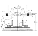
次に、レンズ12への入射経路について図10を参照して説明する。本実施形態では、対角方向の入射角度が最も大きく、147°とし、水平方向を127°、垂直方向を72°とすることが望ましい。上述したレンズ12の頂点よりも2.0mm高い位置では、対角方向では30.32Φの範囲内の光が撮像素子17に入射する。レンズフード11はこの入射光がケラレない寸法とすることが望ましい。本実施形態では、例えばレンズフード11の対角線長さを32mmとすることが望ましい。Here, when the thickness of the
Next, the incident path to the
なお、ここではカメラヘッド筐体13内には、レンズホルダ18、センサ基板19が設けられている。
Here, a
ここで、レンズフード11を32Φの丸型のレンズフードとしてもよい。なお、丸型にした場合、水平方向及び垂直方向の画角は対角方向よりも小さく、それぞれ19.41Φ、7.90Φの範囲で有効な光が入射する。このため、32Φの丸型のレンズフードを用いて光を遮断する場合、遮断できる不要光の割合が低くなってしまう。
Here, the
そのため、本実施形態では角型のレンズフードを採用することがもっとも望ましい。角型のレンズフードは丸型のレンズフードと比較して、水平及び垂直方向の寸法を小さくすることが可能である。そのため、遮光性能を高めることができる。さらにレンズフードの垂直方向の寸法を小さくできるため、その分カメラヘッドを小型化することが可能である。 Therefore, it is most desirable to employ a square lens hood in this embodiment. The rectangular lens hood can be reduced in dimensions in the horizontal and vertical directions compared to the round lens hood. Therefore, the light shielding performance can be improved. Furthermore, since the vertical dimension of the lens hood can be reduced, the camera head can be reduced in size accordingly.
本実施形態のレンズフード11の寸法設計について図11を参照して説明する。上述したように、撮像素子の形状は横縦比が16:9の長方形状である。よって、レンズフード11は撮像素子に対応させた、対角線の長さが32mmで横縦比が16:9の長方形とする。すなわち、本実施形態においては、例えば横の長さを27.9mmとし、縦の長さを15.7mmとすることが望ましい。
The dimension design of the
本国際出願は2013年11月6日に出願された日本国特許出願第2013−230385号に基づく優先権を主張するものであり、日本国特許出願第2013−230385号の全内容を本国際出願に援用する。
This international application claims priority based on Japanese Patent Application No. 2013-230385 filed on November 6, 2013, and the entire contents of Japanese Patent Application No. 2013-230385 are hereby incorporated by reference. Incorporated into.
1 テレビ会議装置
11 レンズフード
12 レンズ
13 カメラヘッド筐体
14 傾斜部
15 爪部
16 爪受け部
17 撮像素子
20 カメラ部
21 カメラヘッド
22 カメラアーム
30 筐体
31 凹部
110 突起
112 両端部
113 中央部DESCRIPTION OF SYMBOLS 1
Claims (6)
前記撮像部を一端で保持する保持部と、
前記撮像部と前記保持部とからなる撮像ユニットを収納する凹部が一側の面に形成された筐体と、
前記凹部内で前記一側の面に略平行に延びる軸線の周りに相対回動可能に連結されたヒンジ部材を含み、前記ヒンジ部材が前記凹部内に収納された状態で該筐体に接続されたヒンジ装置と、を備える撮像装置であって、
前記撮像ユニットは、前記筐体に対し前記ヒンジ装置を介して前記軸線の周りで前記凹部内に収納される収納位置と前記凹部内から突出する突出位置との間を回動し、
前記撮像部は、略長方形状の撮像素子と、前記撮像素子に外部からの光を入射させるレンズと、前記レンズの外周に設けられた略長方形状のレンズフードを備え、
前記レンズフードは、少なくとも、前記撮像部により被写体を撮像するために必要な前記レンズから前記撮像素子に入射させる必要光を確保でき、前記レンズから前記撮像素子へ入射する不要光を遮光する遮光機能を確保できる距離だけ前記レンズ表面の頂点から突出しており、
前記レンズフードは、前記レンズフードと前記レンズとが嵌合された状態で前記レンズの表面を露出させる開口部を有し、
前記開口部の外周に少なくとも3つの突起が相互に等間隔に配置されている
ことを特徴とする撮像装置。 An imaging unit for imaging a subject;
A holding unit for holding the imaging unit at one end;
A housing in which a recess for housing an imaging unit composed of the imaging unit and the holding unit is formed on one surface;
A hinge member coupled in a relatively rotatable manner around an axis extending substantially parallel to the one side surface in the recess, the hinge member being connected to the housing in a state of being housed in the recess. An imaging device comprising:
The imaging unit rotates between the storage position stored in the recess and the protruding position protruding from the recess around the axis with respect to the housing via the hinge device,
The imaging unit includes a substantially rectangular imaging element, a lens that allows light from the outside to enter the imaging element, and a substantially rectangular lens hood provided on an outer periphery of the lens,
The lens hood can secure at least necessary light to be incident on the imaging element from the lens necessary for imaging the subject by the imaging unit, and shields unnecessary light incident on the imaging element from the lens. Projecting from the apex of the lens surface by a distance that can be secured ,
The lens hood has an opening that exposes the surface of the lens in a state where the lens hood and the lens are fitted,
The imaging apparatus, wherein at least three protrusions are arranged at equal intervals on the outer periphery of the opening .
前記傾斜部は、前記レンズフードの被写体側の端面周囲から、該端面より前記撮像素子側に配置される前記レンズフードの開口部周囲に向けて傾斜していることを特徴とする請求項1又は2記載の撮像装置。 The lens hood includes an inclined portion,
The inclined portion from the end surface surrounding the object side of the lens hood claim 1 or, characterized in that it is inclined toward the peripheral openings of the lens hood which is arranged on the imaging element side than the end surface 2. The imaging device according to 2 .
少なくとも前記中央部は、該中央部を挟む前記端部に対して被写体側に突出していることを特徴とする請求項1から3の何れか1項に記載の撮像装置。 On the end surface of the lens hood on the subject side, a center portion and an end portion sandwiching the center portion are provided,
At least the central portion, an imaging apparatus according to any one of claims 1 to 3, characterized in that projecting on the object side with respect to said end portions sandwiching the middle part.
少なくとも前記凹部の前記部分は、弾性部材により形成されていることを特徴とする請求項1から5の何れか1項に記載の撮像装置。 The recess has a portion where the storage position faces the imaging unit when the imaging unit is stored in the storage position;
At least the portion of the recess, the imaging apparatus according to any one of claims 1 to 5, characterized in that it is formed by an elastic member.
Applications Claiming Priority (3)
| Application Number | Priority Date | Filing Date | Title |
|---|---|---|---|
| JP2013230385 | 2013-11-06 | ||
| JP2013230385 | 2013-11-06 | ||
| PCT/JP2014/078321 WO2015068591A1 (en) | 2013-11-06 | 2014-10-24 | Image-capturing device |
Publications (2)
| Publication Number | Publication Date |
|---|---|
| JPWO2015068591A1 JPWO2015068591A1 (en) | 2017-03-09 |
| JP6206503B2 true JP6206503B2 (en) | 2017-10-04 |
Family
ID=53041373
Family Applications (1)
| Application Number | Title | Priority Date | Filing Date |
|---|---|---|---|
| JP2015546602A Active JP6206503B2 (en) | 2013-11-06 | 2014-10-24 | Imaging device |
Country Status (7)
| Country | Link |
|---|---|
| US (1) | US10116845B2 (en) |
| EP (1) | EP3067745B1 (en) |
| JP (1) | JP6206503B2 (en) |
| CN (1) | CN105705992B (en) |
| CA (1) | CA2928322A1 (en) |
| MX (1) | MX2016005782A (en) |
| WO (1) | WO2015068591A1 (en) |
Families Citing this family (8)
| Publication number | Priority date | Publication date | Assignee | Title |
|---|---|---|---|---|
| US20150172522A1 (en) * | 2013-12-16 | 2015-06-18 | Olloclip, Llc | Devices and methods for close-up imaging with a mobile electronic device |
| US20170090272A1 (en) * | 2015-05-12 | 2017-03-30 | Muneer Ayaad | Foldable camera and projector with code activated controls |
| US20190014269A1 (en) * | 2017-07-05 | 2019-01-10 | Motorola Mobility Llc | Device with Lens, Bezel, and Mechanical Upright, and Corresponding Systems and Methods |
| CN210093262U (en) * | 2019-06-12 | 2020-02-18 | Oppo广东移动通信有限公司 | Mobile terminal |
| EP3975539A4 (en) * | 2019-06-28 | 2022-10-12 | Guangdong Oppo Mobile Telecommunications Corp., Ltd. | Aperture diaphragm cover used for camera module, camera assembly and electronic equipment |
| CN110987876A (en) * | 2019-12-24 | 2020-04-10 | 上海蓝长自动化科技有限公司 | Wide-range optical turbidity detection equipment and detection method thereof |
| US11531145B2 (en) * | 2020-03-09 | 2022-12-20 | Motherson Innovations Company Limited | Device for an image acquisition system |
| CN112702500B (en) * | 2020-12-30 | 2023-02-03 | 广州市森锐科技股份有限公司 | Image acquisition device of video conference terminal |
Family Cites Families (19)
| Publication number | Priority date | Publication date | Assignee | Title |
|---|---|---|---|---|
| JPH1010607A (en) * | 1996-06-26 | 1998-01-16 | Asahi Optical Co Ltd | Lens hood |
| JPH1023321A (en) * | 1996-07-05 | 1998-01-23 | Tamron Co Ltd | Image input device |
| US6411332B1 (en) * | 1997-01-07 | 2002-06-25 | Eastman Kodak Company | Digital camera with an articulating capture module |
| JP4320091B2 (en) * | 1999-08-31 | 2009-08-26 | 富士通株式会社 | Expansion unit and portable information processing apparatus |
| JP3938106B2 (en) * | 2003-06-24 | 2007-06-27 | ソニー株式会社 | Lens hood and imaging device |
| JP4812389B2 (en) * | 2004-12-14 | 2011-11-09 | パナソニック株式会社 | Lens hood equipment |
| CA2704932C (en) | 2007-11-07 | 2015-06-23 | Aoti, Inc. | Wound treatment devices |
| JP4647022B2 (en) * | 2008-09-09 | 2011-03-09 | パナソニック株式会社 | Lens hood attachment / detachment mechanism |
| US7775486B2 (en) * | 2008-10-04 | 2010-08-17 | Hewlett-Packard Development Company, L.P. | Webcam assembly with clamp and stand forms |
| IE86454B1 (en) * | 2008-11-18 | 2014-11-05 | Ash Technologies Res Ltd | A handheld viewing device |
| JP5691304B2 (en) * | 2010-09-02 | 2015-04-01 | 株式会社リコー | Conference equipment |
| JP2012054813A (en) * | 2010-09-02 | 2012-03-15 | Ricoh Co Ltd | Casing of conference apparatus, and conference apparatus |
| US8430580B2 (en) * | 2010-11-15 | 2013-04-30 | DigitalOptics Corporation MEMS | Rotationally deployed actuators |
| JP2012141442A (en) * | 2010-12-28 | 2012-07-26 | Sony Corp | Lens protection device, lens unit, and image pickup apparatus |
| JP5754618B2 (en) * | 2011-01-14 | 2015-07-29 | 株式会社リコー | Communication device |
| JP2012235264A (en) * | 2011-04-28 | 2012-11-29 | Ricoh Co Ltd | Conference device |
| JP2013009304A (en) * | 2011-05-20 | 2013-01-10 | Ricoh Co Ltd | Image input device, conference device, image processing control program, and recording medium |
| JP5984046B2 (en) | 2012-05-18 | 2016-09-06 | 株式会社リコー | Imaging device |
| KR102171366B1 (en) * | 2013-09-13 | 2020-10-29 | 엘지이노텍 주식회사 | Camera module |
-
2014
- 2014-10-24 CA CA2928322A patent/CA2928322A1/en not_active Abandoned
- 2014-10-24 JP JP2015546602A patent/JP6206503B2/en active Active
- 2014-10-24 MX MX2016005782A patent/MX2016005782A/en unknown
- 2014-10-24 EP EP14860630.4A patent/EP3067745B1/en active Active
- 2014-10-24 CN CN201480060137.4A patent/CN105705992B/en not_active Expired - Fee Related
- 2014-10-24 WO PCT/JP2014/078321 patent/WO2015068591A1/en active Application Filing
-
2016
- 2016-04-20 US US15/133,346 patent/US10116845B2/en active Active
Also Published As
| Publication number | Publication date |
|---|---|
| CA2928322A1 (en) | 2015-05-14 |
| US20160234412A1 (en) | 2016-08-11 |
| EP3067745A1 (en) | 2016-09-14 |
| EP3067745A4 (en) | 2016-11-16 |
| JPWO2015068591A1 (en) | 2017-03-09 |
| EP3067745B1 (en) | 2018-06-20 |
| US10116845B2 (en) | 2018-10-30 |
| WO2015068591A1 (en) | 2015-05-14 |
| CN105705992B (en) | 2018-09-18 |
| CN105705992A (en) | 2016-06-22 |
| MX2016005782A (en) | 2016-07-18 |
Similar Documents
| Publication | Publication Date | Title |
|---|---|---|
| JP6206503B2 (en) | Imaging device | |
| JP4319444B2 (en) | Imaging device | |
| WO2012063482A1 (en) | Dome camera | |
| US20180324364A1 (en) | Communication apparatus and optical device thereof | |
| JP2009164654A (en) | Compound eye camera module | |
| JPWO2003013127A1 (en) | Mobile terminal | |
| JP2007519329A (en) | System and method for a multi-directional imaging system | |
| CN214225579U (en) | Optical system, periscopic camera and electronic device | |
| JP5984046B2 (en) | Imaging device | |
| JP2017220824A (en) | Entire-celestial-sphere camera | |
| JP5113010B2 (en) | Intercom device entrance cordless handset | |
| JP2007148051A (en) | Photographing lens unit | |
| KR101696683B1 (en) | The portable terminal of recordable pictures | |
| JP2014044429A (en) | Dome-shaped camera | |
| CN101285987A (en) | Imaging apparatus | |
| WO2017197690A1 (en) | Self-timer for mobile terminal | |
| CN218473254U (en) | Recording instrument | |
| JP2014041380A (en) | Dome type camera | |
| JP4358694B2 (en) | Image input device, digital camera, and portable information terminal device | |
| JP2002171447A (en) | Compound eye imaging system, imaging device and electronic equipment | |
| KR101040953B1 (en) | Camera With Mirror Ball And Mobile Phone Having The Same | |
| JP4916002B2 (en) | Imaging device | |
| TWI578778B (en) | Multiple lens system and portable electronic device with same | |
| JP2016038494A (en) | Imaging device | |
| KR100753202B1 (en) | Protective device for photographing device |
Legal Events
| Date | Code | Title | Description |
|---|---|---|---|
| A131 | Notification of reasons for refusal |
Free format text: JAPANESE INTERMEDIATE CODE: A131 Effective date: 20170131 |
|
| A521 | Request for written amendment filed |
Free format text: JAPANESE INTERMEDIATE CODE: A523 Effective date: 20170331 |
|
| TRDD | Decision of grant or rejection written | ||
| A01 | Written decision to grant a patent or to grant a registration (utility model) |
Free format text: JAPANESE INTERMEDIATE CODE: A01 Effective date: 20170808 |
|
| A61 | First payment of annual fees (during grant procedure) |
Free format text: JAPANESE INTERMEDIATE CODE: A61 Effective date: 20170821 |
|
| R151 | Written notification of patent or utility model registration |
Ref document number: 6206503 Country of ref document: JP Free format text: JAPANESE INTERMEDIATE CODE: R151 |