EP3067745A1 - Image-capturing device - Google Patents
Image-capturing device Download PDFInfo
- Publication number
- EP3067745A1 EP3067745A1 EP14860630.4A EP14860630A EP3067745A1 EP 3067745 A1 EP3067745 A1 EP 3067745A1 EP 14860630 A EP14860630 A EP 14860630A EP 3067745 A1 EP3067745 A1 EP 3067745A1
- Authority
- EP
- European Patent Office
- Prior art keywords
- lens
- imaging
- lens hood
- housing
- hood
- Prior art date
- Legal status (The legal status is an assumption and is not a legal conclusion. Google has not performed a legal analysis and makes no representation as to the accuracy of the status listed.)
- Granted
Links
- 238000003384 imaging method Methods 0.000 claims abstract description 91
- 239000012858 resilient material Substances 0.000 claims description 5
- 210000000078 claw Anatomy 0.000 description 9
- 238000005516 engineering process Methods 0.000 description 5
- 230000000593 degrading effect Effects 0.000 description 4
- 230000000694 effects Effects 0.000 description 4
- 239000000463 material Substances 0.000 description 3
- 230000011514 reflex Effects 0.000 description 3
- 230000002411 adverse Effects 0.000 description 2
- 238000010586 diagram Methods 0.000 description 2
- 230000010365 information processing Effects 0.000 description 2
- 230000002093 peripheral effect Effects 0.000 description 2
- 238000010521 absorption reaction Methods 0.000 description 1
- 239000000945 filler Substances 0.000 description 1
- 238000012986 modification Methods 0.000 description 1
- 230000004048 modification Effects 0.000 description 1
- 230000001012 protector Effects 0.000 description 1
- 238000006748 scratching Methods 0.000 description 1
- 230000002393 scratching effect Effects 0.000 description 1
- 238000007493 shaping process Methods 0.000 description 1
- 239000000758 substrate Substances 0.000 description 1
- 230000000007 visual effect Effects 0.000 description 1
Images


Classifications
-
- G—PHYSICS
- G03—PHOTOGRAPHY; CINEMATOGRAPHY; ANALOGOUS TECHNIQUES USING WAVES OTHER THAN OPTICAL WAVES; ELECTROGRAPHY; HOLOGRAPHY
- G03B—APPARATUS OR ARRANGEMENTS FOR TAKING PHOTOGRAPHS OR FOR PROJECTING OR VIEWING THEM; APPARATUS OR ARRANGEMENTS EMPLOYING ANALOGOUS TECHNIQUES USING WAVES OTHER THAN OPTICAL WAVES; ACCESSORIES THEREFOR
- G03B11/00—Filters or other obturators specially adapted for photographic purposes
- G03B11/04—Hoods or caps for eliminating unwanted light from lenses, viewfinders or focusing aids
-
- G—PHYSICS
- G02—OPTICS
- G02B—OPTICAL ELEMENTS, SYSTEMS OR APPARATUS
- G02B7/00—Mountings, adjusting means, or light-tight connections, for optical elements
- G02B7/02—Mountings, adjusting means, or light-tight connections, for optical elements for lenses
-
- G—PHYSICS
- G03—PHOTOGRAPHY; CINEMATOGRAPHY; ANALOGOUS TECHNIQUES USING WAVES OTHER THAN OPTICAL WAVES; ELECTROGRAPHY; HOLOGRAPHY
- G03B—APPARATUS OR ARRANGEMENTS FOR TAKING PHOTOGRAPHS OR FOR PROJECTING OR VIEWING THEM; APPARATUS OR ARRANGEMENTS EMPLOYING ANALOGOUS TECHNIQUES USING WAVES OTHER THAN OPTICAL WAVES; ACCESSORIES THEREFOR
- G03B11/00—Filters or other obturators specially adapted for photographic purposes
- G03B11/04—Hoods or caps for eliminating unwanted light from lenses, viewfinders or focusing aids
- G03B11/045—Lens hoods or shields
-
- G—PHYSICS
- G03—PHOTOGRAPHY; CINEMATOGRAPHY; ANALOGOUS TECHNIQUES USING WAVES OTHER THAN OPTICAL WAVES; ELECTROGRAPHY; HOLOGRAPHY
- G03B—APPARATUS OR ARRANGEMENTS FOR TAKING PHOTOGRAPHS OR FOR PROJECTING OR VIEWING THEM; APPARATUS OR ARRANGEMENTS EMPLOYING ANALOGOUS TECHNIQUES USING WAVES OTHER THAN OPTICAL WAVES; ACCESSORIES THEREFOR
- G03B17/00—Details of cameras or camera bodies; Accessories therefor
- G03B17/02—Bodies
-
- H—ELECTRICITY
- H04—ELECTRIC COMMUNICATION TECHNIQUE
- H04N—PICTORIAL COMMUNICATION, e.g. TELEVISION
- H04N23/00—Cameras or camera modules comprising electronic image sensors; Control thereof
- H04N23/50—Constructional details
- H04N23/51—Housings
-
- H—ELECTRICITY
- H04—ELECTRIC COMMUNICATION TECHNIQUE
- H04N—PICTORIAL COMMUNICATION, e.g. TELEVISION
- H04N23/00—Cameras or camera modules comprising electronic image sensors; Control thereof
- H04N23/50—Constructional details
- H04N23/54—Mounting of pick-up tubes, electronic image sensors, deviation or focusing coils
-
- H—ELECTRICITY
- H04—ELECTRIC COMMUNICATION TECHNIQUE
- H04N—PICTORIAL COMMUNICATION, e.g. TELEVISION
- H04N23/00—Cameras or camera modules comprising electronic image sensors; Control thereof
- H04N23/50—Constructional details
- H04N23/55—Optical parts specially adapted for electronic image sensors; Mounting thereof
-
- H—ELECTRICITY
- H04—ELECTRIC COMMUNICATION TECHNIQUE
- H04N—PICTORIAL COMMUNICATION, e.g. TELEVISION
- H04N7/00—Television systems
- H04N7/14—Systems for two-way working
- H04N7/141—Systems for two-way working between two video terminals, e.g. videophone
- H04N7/142—Constructional details of the terminal equipment, e.g. arrangements of the camera and the display
-
- H—ELECTRICITY
- H04—ELECTRIC COMMUNICATION TECHNIQUE
- H04N—PICTORIAL COMMUNICATION, e.g. TELEVISION
- H04N7/00—Television systems
- H04N7/14—Systems for two-way working
- H04N7/15—Conference systems
Definitions
- An aspect in the following disclosure relates to an imaging device provided with a lens protecting mechanism.
- Conference systems capable of being used to conduct a remote conference between remote places via communications networks such as the Internet have become popular.
- Such conference systems utilize a technology known in the art to conduct a remote conference; that is, a communications apparatus acquires images and speech of conference participants in one conference room, converts the acquired images and speech into digital data, and transmits the converted digital data to a counterpart communications apparatus.
- the counterpart communications apparatus subsequently displays the acquired images and outputs the speech in a counterpart conference room so that conference participants in two remotely separate conference rooms can conduct a remote conference in a state close to an actual conference.
- Patent Document 1 discloses a communications apparatus having excellent portability as an example of the above technology.
- the disclosed communications apparatus has a uniaxial hinge configured to pivotally connect an image input unit including a digital camera and a housing.
- Patent Document 1 Japanese Unexamined Patent Application Publication No. 2012-151521
- Patent Document 1 may improve portability and operability of the communications apparatus because the disclosed technology enables the communications apparatus to house a camera arm to protect a camera lens, thereby no longer requiring a lens cap attached to the communications apparatus so as to eliminate inefficient operations of attaching and detaching the lens whenever the communications apparatus is used and unused.
- the technology disclosed in Patent Document 1 may further provide the communications apparatus with a protruding object and a lens filter to prevent the lens from contacting the housing when housing the camera arm.
- an imaging device that includes an imaging unit having an imaging part configured to image a subject, and a holder configured to hold the imaging part at one end thereof; a housing including a recess part formed in a first surface thereof, and configured to house the imaging unit; and a hinge device having a hinge member housed in the recess part pivotally coupled to the housing around an axle extending approximately in parallel with the first surface inside the recess part of the housing.
- the imaging unit pivots around the axle via the hinge device between a housing position at which the imaging unit is housed inside the recess part of the housing and a projecting position at which the imaging unit is projected from the recess part of the housing.
- the imaging part includes an imaging element having an approximately rectangular shape, a lens configured to introduce external light into the imaging element, and a lens hood mounted at an outer periphery of the lens.
- the lens hood projects from a surface of the lens by a distance to allow the imaging part to introduce light necessary for imaging a subject from the lens into the imaging element and to block unnecessary light introduced from the lens into the imaging element.
- the following embodiment illustrates a TV conference apparatus illustrated in FIGS. 1 and 2 as an example of an apparatus provided with an imaging device according to an embodiment.
- the invention is not limited to the TV conference.
- the invention may include a communications apparatus such as a camcorder, a digital still camera, and a TV conference apparatus, or an information processing apparatus such as a smartphone.
- the invention applied may further include an imaging device, a communications apparatus, and an information processing apparatus of another type that incorporates an imaging part in a housing of a main body.
- FIG. 1 is an external view illustrating the TV conference apparatus 1 that is unused.
- the TV conference apparatus 1 that is unused has a substantially thin and oblong rectangular parallelepiped outer shape or a substantially plate-like outer shape.
- the TV conference apparatus 1 may be placed on a table or a desk parallel to a horizontal plane.
- the TV conference apparatus 1 includes a camera part 20 serving as an imaging unit composed of a camera head 21 and a camera arm 22, and a housing 30.
- the camera head 21 serves as an imaging part configured to image a subject
- the camera arm 22 serves as a holder configured to hold the camera head 21 at one end.
- the housing 30 has a recess part 31 as an upper surface of one side, which is configured to house the camera part 20.
- the camera part 20 that is not being used is housed in the recess part 31, as illustrated in FIG. 1 . This facilitates users' carrying the TV conference apparatus 1, thereby improving its portability.
- the camera part 20 corresponds to an imaging device.
- the TV conference apparatus 1 is provided with a hinge device H.
- the hinge device H includes a hinge member connected to the housing 30 inside the recess part 31 relatively and pivotally around an axle extending in substantially parallel with the upper surface inside the recess part 31 of the TV conference apparatus 1.
- the camera part 20 pivotally moves via a pivoting shaft of the hinge device H in a pivoting direction R to a position perpendicular to the housing 30.
- the camera part 20 is configured to pivotally moves between a housing position S and projecting position T.
- the housing position S is a position around the axle at which the camera part 20 is housed via the hinge device H inside the recess part 31, and the projecting position T is a position at which the camera part 20 projects from the recess part 31.
- the TV conference apparatus 1 when it is used is configured to pivotally move the camera part 20 from the housing position S to the projecting position T, thereby matching the user's eye and a height of the camera head 21.
- a position of the images projected from the camera part 20 onto a predetermined projecting part thus matches the user's eye to facilitate the user's observation of the projected images.
- the camera part 20 that is in use is vertically projected from the housing 30, which is not easy for the user to carry.
- the TV conference apparatus 1 according to the embodiment is configured to house the camera part 20 inside the recess part 31 to enable the user to easily carry the TV conference apparatus 1, thereby improving the portability of the TV conference apparatus 1.
- the structural features of the TV conference apparatus 1 further include a lens hood configured to protect a lens part of the camera part 20 from external impacts and dirt when the camera part 20 is housed in the housing 30, and prevent the damage to the lens part caused by contact between the housed lens part and the surface of the housing 30.
- a typical digital single-lens reflex camera or a camcorder has a lens hood simply attached to the camera lens, and the lens hood of this configuration does not serve as a protector to prevent the camera lens from being damaged when the camera is housed.
- the digital single-lens reflex camera or the camcorder uses a lens cover to simply protect a lens surface from scratching or dirt. That is, the digital single-lens reflex camera or the camcorder needs to have a separate lens cover.
- the lens contacts the housing 30 without the lens hood when the camera part 20 is housed in the recess part 31.
- the lens may strongly contact the housing 30. This may damage the lens due to impact.
- the lens may be protected by attaching a protruding object around the lens.
- the protruding object may have a shape that interferes with rays of light incident on the lens, generating so-called vignetting that is physically introducing a shadow in an image taken.
- simply providing a protruding object for protecting the lens may fail to improve the quality of the image.
- the present embodiment there may be employed a later-described lens hood having a specific feature in addition to the above-described pivoting mechanism of the camera arm 22.
- the features capable of protecting the lens without a complicated mechanism and avoiding inefficient operations as well as preventing the quality of the acquired images from degrading due to undesired light.
- lifting the camera arm when using the TV conference apparatus 1 achieves an operation of detaching a lens cap in the typical camera or the like. That is, the TV conference apparatus 1 according to the embodiment provides an effect of omitting the operation of detaching the lens cap.
- the camera head 21 of the embodiment includes an imaging element 17 (see FIG. 10 ) having a substantially rectangular shape with an aspect ratio of 16:9, a lens 12 introducing external light into the imaging element 17, and a lens hood 11 having a substantially rectangular shape disposed on an outer periphery of the lens 12.
- the lens hood 11 having the substantially rectangular shape may have the same height in a horizontal direction since the shape of the lens hood 11 is roughly similar to the shape of the imaging element 17. That is, the lens hood has approximately the same height in vertical and horizontal directions, having taken account of the light incident on the imaging element 17.
- the recess part 31 may be shaped to match the shape of the lens hood 11; however, it is not preferable to shape the recess part 31 into a complex form.
- FIG. 3 is a perspective view illustrating an example of an appearance of the camera head 21.
- the lens hood 11 covers an outer circumferential edge of the lens part at an end of a camera head housing 13.
- the lens hood 11 includes a gradient part 14 inclined downward from an outer peripheral end on a subject side (outside) of the lens hood 11 to an opening peripheral end on the imaging element side of the lens hood 11.
- the lens hood 11 includes a stepwise gradient part 14, for example (see FIGS. 3 to 6 ). This may reduce the proportion of reflection light incident on the lens 12 inside the lens hood 11.
- the lens hood 11 may preferably be painted black to further reduce the reflection light.
- the lens hood 11 further includes three protruding objects 110 mutually arranged at equal intervals on an outer periphery of an opening part K of the lens hood 11, which is fitted with the lens 12 to expose a surface of the lens 12 from the opening part K.
- the lens 12 may be deflected toward the center of the lens hood 11, which may shield the light incident on the imaging element 17. Further, this configuration of the lens hood 11 and the lens 12 without having the protruding objects 110 in between may allow a gap between the lens hood 11 and the lens 12 to visually stand out conspicuously.
- arranging at least three protruding objects 110 mutually at equal internals on the outer periphery of the opening part K of the lens hood 11 may position the lens 12 at the center of the lens hood 11 to sufficiently introduce the incident light into the imaging element 17 as well as making the gap between the lens hood 11 and the lens 12 to visually less stand out.
- claw parts 15 serving as attaching units are mounted on a rear surface of the lens hood 11; two of the claw parts 15 being mounted at an upper part of the rear face and two of the image forming apparatus 13 being mounted at a lower part of the rear surface to face the claw parts 15 at the upper part.
- the claw parts 15 each include claws directed outward, and are configured to attach the lens hood 11 to the image forming apparatus 13.
- the lens hood 11 is attached to the image forming apparatus 13 by fitting the claw parts 15 into counterpart claw receivers 16 formed in the image forming apparatus 13 illustrated in FIG. 9 .
- an elastic member such as rubber or sponge may be included inside the lens hood 11 instead to serve as the above-described locators and filler for filling the gap between the lens hood 11 and the lens 12.
- the lens hood 11 may be formed of a resilient material such as a cushion material (buffer material). Further, a part of the recess part 31 of the housing 30 that faces the camera head 21 housed in the recess part 31 at the housing position S may be formed of a resilient material such as a cushion material. The application of the above-described configuration may improve an impact absorption effect of the camera head 21 or the lens 12.
- a middle part 113 of the lens hood 11 has an end face 111 projected toward a subject side of the lens hood 11 with respect to two opposing ends sandwiching the middle part 113 as illustrated in FIG. 8 .
- the middle part 113 of the end face 111 in a longitudinal direction of the lens hood 11 forms a gradual projection with respect to left and right ends of the end face 111 of the lens hood 11.
- the end face 111 indicates a part of an end face on one side in an approximately rectangular shape of the end face 111.
- the middle part 113 may be projected from the opposing ends 112 such that a difference in height between a tangent Y to the middle part 113 and a line segment Z connecting between the opposing ends 112 is approximately 1.0 mm.
- This structural configuration may restrict a position of the lens hood 11 coming in contact with the recess part 31 to the middle part 113 when the camera part 20 is housed in the recess part 31 of the housing 30.
- the reason for determining the difference in height to be approximately 1.0 mm is, as illustrated earlier, to form the recess part 31 having a shallow depth. This is because forming the recess part 31 having a greater depth leads to an undesired increase in the thickness of the housing 30.
- a projecting part with respect to the opposing ends is not limited to the middle part 113, and any part of the end part may be projected with respect to other parts of the end part.
- the middle parts 113 of both an upper end face and a lower end face in the longitudinal direction of the lens hood 11 may be projected with respect to the opposing ends 112.
- the overall part of the lens hood 11 may acquire fine scratches due to the contact between the lens hood 11 and the housing 30 when the lens hood 11 is housed in the housing 30, thereby degrading the appearance of the lens hood 11.
- the structural configuration of the lens hood 11 restricts a position to acquire such fine scratches due to the contact between the lens hood 11 and the housing 30 to a specific position of the lens hood 11, thereby allowing the scratch to be unnoticeable to improve a design property.
- the following illustrates a featured structure of the lens hood 11 according to the embodiment with reference to FIGS. 10 and 11 .
- the TV conference apparatus 1 preferably employ a wide angle camera to capture all the conference participants in an imaging visual field.
- the apparatus employing a wide angle camera generally needs to introduce rays of light into the imaging element 17 in a wider range of angles, which leads to a total length of the lens hood to be short; that is, a distance from the lens to the lens hood 11 is short.
- the lens hood is configured to block strong rays of light introduced from outside the imaging view angle, and hence prevent an adverse phenomenon such as lens flare.
- the lens hood may provide higher effect on preventing the adverse phenomenon as the lens hood blocks unnecessary light in a wider range.
- the lens hood may also need to introduce an amount of light necessary for imaging the subject into the imaging element 17 through the lens.
- the lens hood 11 may have a projection with a distance from the surface of the lens 12 to acquire light necessary for imaging the subject by the camera head 21 to be introduced from the lens 12 into the imaging element 17 and to block unnecessary light to be introduced from the lens 12 into the imaging element 17.
- the lens hood 11 of the embodiment is designed as follows. Dimensions of the lens hood 11 are calculated based on an angle incident on the lens and an effective area of the imaging element 17.
- the imaging element 17 of the camera head 21 has a landscape-oriented rectangular shape having an aspect ratio of 16:9. Since the imaging element 17 of the embodiment has a landscape-oriented rectangular shape, the imaging element 17 has a rectangular shape having a short length in a vertical direction and a greater width in a horizontal direction. Further, the imaging element 17 of the camera head 21 has a maximum angle of view in a diagonal direction.
- the TV conference apparatus 1 is configured to protect the lens 12 by the lens hood 11, where the lens hood 11 is desired to project from a top of the lens by approximately 1.0 mm.
- the TV conference apparatus 1 may preferably have a structural configuration in which a top of the lens hood 11 is at a position 2.0 mm higher than the top of the lens 12.
- a projecting distance R from a top of the surface of the lens 12 of the lens hood 11 is preferably 1.0 mm ⁇ R ⁇ 2.0 mm.
- the top of the lens hood 11 may be at a higher position. However, this increases a thickness of the camera head housing 13 due to the configuration of the camera head 21 allowing to house the camera part 20 when the TV conference apparatus 1 is unused.
- the thickness of the camera head housing 13 to be set may preferably be less than 40 mm.
- the TV conference apparatus 1 of the embodiment has the thickness of the camera head housing 13 excluding the lens hood 11 being 30 mm.
- the upper limit of the height of the lens hood 11 may preferably be approximately 5.0 mm.
- the TV conference apparatus 1 of the embodiment may desirably be compact.
- a preferable height of the lens hood 11 may be, for example, approximately 2.0 mm.
- the maximum incident angle is obtained in the diagonal direction, and is preferably 147°, the incident angle in the horizontal direction is preferably 127°, and the incident angle in the vertical direction is preferably 72°.
- Light is incident on the imaging element 17 within a diameter range of 30.32 mm at a position 2.0 mm higher than the top of the above-described lens 12.
- the lens hood 11 preferably has dimensions to introduce incident light into the imaging element 17 without vignetting.
- the camera head 21 may preferably have a diagonal length of the lens hood 11 to be 32 mm.
- a lens holder 18 and a sensor substrate 19 are further mounted within the camera head housing 13.
- the lens hood 11 may have a round shape having a diameter of 32 mm. Note that in this example of having a round diameter, the angle of view in the horizontal direction and the angle of view in the vertical direction are smaller than the angle of view in the diagonal direction, and effective incident light is incident within a corresponding diameter range of 19.4 mm and 7.90 mm. Thus, the lens hood 11 having a diameter of 32 mm may lower a proportion of unnecessary light to be blocked by the lens hood 11.
- the TV conference apparatus 1 of the embodiment may preferably employ a square lens hood.
- the square lend hood may have smaller dimensions in the horizontal and the vertical directions compared to the round lens hood.
- the TV conference apparatus 1 of the embodiment having the square lend hood may improve light shielding performance.
- the TV conference apparatus 1 of the embodiment having the square lend hood may have a compact camera head because the dimensions of the lens hood in the vertical direction are reduced.
- the imaging element 17 of the camera head 21 has a landscape-oriented rectangular shape having an aspect ratio of 16:9.
- the lens hood 11 thus has a rectangular shape having a diagonal length of 32 mm and an aspect ratio of 16:9. This indicates that the lens hood 11 may preferably have a lateral length of 27.9 mm, and a vertical length of 15.7 mm, for example.
Abstract
Description
- An aspect in the following disclosure relates to an imaging device provided with a lens protecting mechanism.
- Conference systems capable of being used to conduct a remote conference between remote places via communications networks such as the Internet have become popular. Such conference systems utilize a technology known in the art to conduct a remote conference; that is, a communications apparatus acquires images and speech of conference participants in one conference room, converts the acquired images and speech into digital data, and transmits the converted digital data to a counterpart communications apparatus. The counterpart communications apparatus subsequently displays the acquired images and outputs the speech in a counterpart conference room so that conference participants in two remotely separate conference rooms can conduct a remote conference in a state close to an actual conference.
- Patent Document 1, for example, discloses a communications apparatus having excellent portability as an example of the above technology. The disclosed communications apparatus has a uniaxial hinge configured to pivotally connect an image input unit including a digital camera and a housing.
- [Patent Document 1] Japanese Unexamined Patent Application Publication No.
2012-151521 - The technology disclosed in Patent Document 1 may improve portability and operability of the communications apparatus because the disclosed technology enables the communications apparatus to house a camera arm to protect a camera lens, thereby no longer requiring a lens cap attached to the communications apparatus so as to eliminate inefficient operations of attaching and detaching the lens whenever the communications apparatus is used and unused. The technology disclosed in Patent Document 1 may further provide the communications apparatus with a protruding object and a lens filter to prevent the lens from contacting the housing when housing the camera arm.
- It is one of objects of the present invention to solve such problems. In other words, it is an object of the present invention to provide a communications apparatus capable of protecting the lens without a complicated mechanism and avoid inefficient operations as well as preventing the quality of the acquired images from degrading due to undesired light.
- According to an aspect in the disclosure, there is proviced an imaging device that includes an imaging unit having an imaging part configured to image a subject, and a holder configured to hold the imaging part at one end thereof; a housing including a recess part formed in a first surface thereof, and configured to house the imaging unit; and a hinge device having a hinge member housed in the recess part pivotally coupled to the housing around an axle extending approximately in parallel with the first surface inside the recess part of the housing. The imaging unit pivots around the axle via the hinge device between a housing position at which the imaging unit is housed inside the recess part of the housing and a projecting position at which the imaging unit is projected from the recess part of the housing. The imaging part includes an imaging element having an approximately rectangular shape, a lens configured to introduce external light into the imaging element, and a lens hood mounted at an outer periphery of the lens. The lens hood projects from a surface of the lens by a distance to allow the imaging part to introduce light necessary for imaging a subject from the lens into the imaging element and to block unnecessary light introduced from the lens into the imaging element.
- According to an aspect in the disclosure, it is possible to protect a lens without a complicated mechanism and avoid inefficient operations as well as preventing the quality of the acquired images from degrading due to undesired light.
-
-
FIG. 1 is a schematic perspective view illustrating an imaging apparatus according to an embodiment; -
FIG. 2 is a schematic perspective view illustrating an imaging apparatus according to the embodiment; -
FIG. 3 is a schematic perspective view illustrating an imaging part according to the embodiment; -
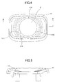
FIG. 4 is a front view illustrating a lens hood according to the embodiment; -
FIG. 5 is a cross-sectional view illustrating the lens hood according to the embodiment; -
FIG. 6 is a perspective view illustrating the lens hood according to the embodiment; -
FIG. 7 is a perspective view illustrating the lens hood according to the embodiment; -
FIG. 8 is a top view illustrating the lens hood according to the embodiment; -
FIG. 9 is a perspective view illustrating a housing of the imaging part according to the embodiment; -
FIG. 10 is a schematic diagram illustrating a design of the lens hood according to the embodiment; and -
FIG. 11 is a schematic diagram illustrating the design of the lens hood according to the embodiment. - In the following, an imaging device according to an embodiment of the present invention will be described with reference to the accompanying drawings; however, the present invention is not limited to the specifically disclosed embodiment within the gist of the present invention. Note that the same or similar components are provided with the same reference numbers in the drawings to omit or partially omit duplicated illustration.
- The following embodiment illustrates a TV conference apparatus illustrated in
FIGS. 1 and 2 as an example of an apparatus provided with an imaging device according to an embodiment. However, the invention is not limited to the TV conference. The invention may include a communications apparatus such as a camcorder, a digital still camera, and a TV conference apparatus, or an information processing apparatus such as a smartphone. The invention applied may further include an imaging device, a communications apparatus, and an information processing apparatus of another type that incorporates an imaging part in a housing of a main body. - The following illustrates a schematic configuration of a TV conference apparatus 1 as an apparatus having an imaging device according to an embodiment with reference to
FIGS. 1 and 2. FIG. 1 is an external view illustrating the TV conference apparatus 1 that is unused. The TV conference apparatus 1 that is unused has a substantially thin and oblong rectangular parallelepiped outer shape or a substantially plate-like outer shape. The TV conference apparatus 1 may be placed on a table or a desk parallel to a horizontal plane. - The TV conference apparatus 1 includes a
camera part 20 serving as an imaging unit composed of acamera head 21 and acamera arm 22, and ahousing 30. Thecamera head 21 serves as an imaging part configured to image a subject, and thecamera arm 22 serves as a holder configured to hold thecamera head 21 at one end. Thehousing 30 has arecess part 31 as an upper surface of one side, which is configured to house thecamera part 20. Thecamera part 20 that is not being used is housed in therecess part 31, as illustrated inFIG. 1 . This facilitates users' carrying the TV conference apparatus 1, thereby improving its portability. Thecamera part 20 corresponds to an imaging device. - Next, an illustration is given of the TV conference apparatus 1 that is used with additional reference to
FIG. 2 . In this example, the TV conference apparatus 1 is provided with a hinge device H. The hinge device H includes a hinge member connected to thehousing 30 inside therecess part 31 relatively and pivotally around an axle extending in substantially parallel with the upper surface inside therecess part 31 of the TV conference apparatus 1. When thecamera part 20 is used, thecamera part 20 pivotally moves via a pivoting shaft of the hinge device H in a pivoting direction R to a position perpendicular to thehousing 30. - The following specifically describes a pivoting mechanism of the
camera part 20. Thecamera part 20 is configured to pivotally moves between a housing position S and projecting position T. The housing position S is a position around the axle at which thecamera part 20 is housed via the hinge device H inside therecess part 31, and the projecting position T is a position at which thecamera part 20 projects from therecess part 31. - The TV conference apparatus 1 according to the embodiment when it is used is configured to pivotally move the
camera part 20 from the housing position S to the projecting position T, thereby matching the user's eye and a height of thecamera head 21. A position of the images projected from thecamera part 20 onto a predetermined projecting part thus matches the user's eye to facilitate the user's observation of the projected images. - The
camera part 20 that is in use is vertically projected from thehousing 30, which is not easy for the user to carry. However, the TV conference apparatus 1 according to the embodiment is configured to house thecamera part 20 inside therecess part 31 to enable the user to easily carry the TV conference apparatus 1, thereby improving the portability of the TV conference apparatus 1. - The structural features of the TV conference apparatus 1 further include a lens hood configured to protect a lens part of the
camera part 20 from external impacts and dirt when thecamera part 20 is housed in thehousing 30, and prevent the damage to the lens part caused by contact between the housed lens part and the surface of thehousing 30. - Note that a typical digital single-lens reflex camera or a camcorder has a lens hood simply attached to the camera lens, and the lens hood of this configuration does not serve as a protector to prevent the camera lens from being damaged when the camera is housed. The digital single-lens reflex camera or the camcorder uses a lens cover to simply protect a lens surface from scratching or dirt. That is, the digital single-lens reflex camera or the camcorder needs to have a separate lens cover.
- The lens contacts the
housing 30 without the lens hood when thecamera part 20 is housed in therecess part 31. For example, when a user replaces thecamera arm 22 strongly, the lens may strongly contact thehousing 30. This may damage the lens due to impact. - On the other hand, the lens may be protected by attaching a protruding object around the lens. However, the protruding object may have a shape that interferes with rays of light incident on the lens, generating so-called vignetting that is physically introducing a shadow in an image taken. Thus, simply providing a protruding object for protecting the lens may fail to improve the quality of the image.
- In the present embodiment, there may be employed a later-described lens hood having a specific feature in addition to the above-described pivoting mechanism of the
camera arm 22. Thus, in the embodiment, there may be the features capable of protecting the lens without a complicated mechanism and avoiding inefficient operations as well as preventing the quality of the acquired images from degrading due to undesired light. Note that in the TV conference apparatus 1 according to the embodiment, lifting the camera arm when using the TV conference apparatus 1 achieves an operation of detaching a lens cap in the typical camera or the like. That is, the TV conference apparatus 1 according to the embodiment provides an effect of omitting the operation of detaching the lens cap. - The following describes a schematic configuration of the
camera head 21 provided with theAD server apparatus 11 of the present embodiment with reference toFIGS. 3 to 9 . Thecamera head 21 of the embodiment includes an imaging element 17 (seeFIG. 10 ) having a substantially rectangular shape with an aspect ratio of 16:9, alens 12 introducing external light into theimaging element 17, and alens hood 11 having a substantially rectangular shape disposed on an outer periphery of thelens 12. Thelens hood 11 having the substantially rectangular shape may have the same height in a horizontal direction since the shape of thelens hood 11 is roughly similar to the shape of theimaging element 17. That is, the lens hood has approximately the same height in vertical and horizontal directions, having taken account of the light incident on theimaging element 17. This facilitates forming thelens hood 11, and further shaping therecess part 31 into a planer shape for placing thecamera part 20 into therecess part 31 at the housing position S. Note that therecess part 31 may be shaped to match the shape of thelens hood 11; however, it is not preferable to shape therecess part 31 into a complex form. -
FIG. 3 is a perspective view illustrating an example of an appearance of thecamera head 21. Thelens hood 11 covers an outer circumferential edge of the lens part at an end of acamera head housing 13. - The
lens hood 11 includes agradient part 14 inclined downward from an outer peripheral end on a subject side (outside) of thelens hood 11 to an opening peripheral end on the imaging element side of thelens hood 11. Thelens hood 11 includes astepwise gradient part 14, for example (seeFIGS. 3 to 6 ). This may reduce the proportion of reflection light incident on thelens 12 inside thelens hood 11. - Note that the
lens hood 11 may preferably be painted black to further reduce the reflection light. - As illustrated in
FIG. 4 , thelens hood 11 further includes three protrudingobjects 110 mutually arranged at equal intervals on an outer periphery of an opening part K of thelens hood 11, which is fitted with thelens 12 to expose a surface of thelens 12 from the opening part K. - Note that when the
lens hood 11 is not provided with the protrudingobjects 110, thelens 12 may be deflected toward the center of thelens hood 11, which may shield the light incident on theimaging element 17. Further, this configuration of thelens hood 11 and thelens 12 without having the protrudingobjects 110 in between may allow a gap between thelens hood 11 and thelens 12 to visually stand out conspicuously. Thus, arranging at least three protrudingobjects 110 mutually at equal internals on the outer periphery of the opening part K of thelens hood 11 may position thelens 12 at the center of thelens hood 11 to sufficiently introduce the incident light into theimaging element 17 as well as making the gap between thelens hood 11 and thelens 12 to visually less stand out. - As illustrated in
FIGS. 6, 7 , and8 , fourclaw parts 15 serving as attaching units are mounted on a rear surface of thelens hood 11; two of theclaw parts 15 being mounted at an upper part of the rear face and two of theimage forming apparatus 13 being mounted at a lower part of the rear surface to face theclaw parts 15 at the upper part. Theclaw parts 15 each include claws directed outward, and are configured to attach thelens hood 11 to theimage forming apparatus 13. Thelens hood 11 is attached to theimage forming apparatus 13 by fitting theclaw parts 15 intocounterpart claw receivers 16 formed in theimage forming apparatus 13 illustrated inFIG. 9 . - Alternatively, an elastic member such as rubber or sponge may be included inside the
lens hood 11 instead to serve as the above-described locators and filler for filling the gap between thelens hood 11 and thelens 12. - Further, the
lens hood 11 may be formed of a resilient material such as a cushion material (buffer material). Further, a part of therecess part 31 of thehousing 30 that faces thecamera head 21 housed in therecess part 31 at the housing position S may be formed of a resilient material such as a cushion material. The application of the above-described configuration may improve an impact absorption effect of thecamera head 21 or thelens 12. - Further, a
middle part 113 of thelens hood 11 has anend face 111 projected toward a subject side of thelens hood 11 with respect to two opposing ends sandwiching themiddle part 113 as illustrated inFIG. 8 . For example, themiddle part 113 of theend face 111 in a longitudinal direction of thelens hood 11 forms a gradual projection with respect to left and right ends of theend face 111 of thelens hood 11. Note that theend face 111 indicates a part of an end face on one side in an approximately rectangular shape of theend face 111. - More specifically, the
middle part 113 may be projected from the opposing ends 112 such that a difference in height between a tangent Y to themiddle part 113 and a line segment Z connecting between the opposing ends 112 is approximately 1.0 mm. This structural configuration may restrict a position of thelens hood 11 coming in contact with therecess part 31 to themiddle part 113 when thecamera part 20 is housed in therecess part 31 of thehousing 30. Note that the reason for determining the difference in height to be approximately 1.0 mm is, as illustrated earlier, to form therecess part 31 having a shallow depth. This is because forming therecess part 31 having a greater depth leads to an undesired increase in the thickness of thehousing 30. Note that a projecting part with respect to the opposing ends is not limited to themiddle part 113, and any part of the end part may be projected with respect to other parts of the end part. Alternatively, themiddle parts 113 of both an upper end face and a lower end face in the longitudinal direction of thelens hood 11 may be projected with respect to the opposing ends 112. - If the end face of the
lens hood 11 is flat, the overall part of thelens hood 11 may acquire fine scratches due to the contact between thelens hood 11 and thehousing 30 when thelens hood 11 is housed in thehousing 30, thereby degrading the appearance of thelens hood 11. By contrast, the structural configuration of thelens hood 11 restricts a position to acquire such fine scratches due to the contact between thelens hood 11 and thehousing 30 to a specific position of thelens hood 11, thereby allowing the scratch to be unnoticeable to improve a design property. - Note that it is not necessary to form a part of the above-described
recess part 31 facing thecamera head 21 with a resilient material. - The following illustrates a featured structure of the
lens hood 11 according to the embodiment with reference toFIGS. 10 and 11 . The TV conference apparatus 1 according to the embodiment preferably employ a wide angle camera to capture all the conference participants in an imaging visual field. The apparatus employing a wide angle camera generally needs to introduce rays of light into theimaging element 17 in a wider range of angles, which leads to a total length of the lens hood to be short; that is, a distance from the lens to thelens hood 11 is short. - Note that the lens hood is configured to block strong rays of light introduced from outside the imaging view angle, and hence prevent an adverse phenomenon such as lens flare. The lens hood may provide higher effect on preventing the adverse phenomenon as the lens hood blocks unnecessary light in a wider range. On the other hand, the lens hood may also need to introduce an amount of light necessary for imaging the subject into the
imaging element 17 through the lens. - To reduce contradiction between the two opposing factors, the
lens hood 11 may have a projection with a distance from the surface of thelens 12 to acquire light necessary for imaging the subject by thecamera head 21 to be introduced from thelens 12 into theimaging element 17 and to block unnecessary light to be introduced from thelens 12 into theimaging element 17. - Specifically, the
lens hood 11 of the embodiment is designed as follows. Dimensions of thelens hood 11 are calculated based on an angle incident on the lens and an effective area of theimaging element 17. Theimaging element 17 of thecamera head 21 has a landscape-oriented rectangular shape having an aspect ratio of 16:9. Since theimaging element 17 of the embodiment has a landscape-oriented rectangular shape, theimaging element 17 has a rectangular shape having a short length in a vertical direction and a greater width in a horizontal direction. Further, theimaging element 17 of thecamera head 21 has a maximum angle of view in a diagonal direction. - The TV conference apparatus 1 is configured to protect the
lens 12 by thelens hood 11, where thelens hood 11 is desired to project from a top of the lens by approximately 1.0 mm. In order to allow a tolerance of ±0.5 mm and an individual difference in a distance of approximately 0.5 mm from thelens 12 to theimaging element 17 for adjusting a focal distance at assembling, the TV conference apparatus 1 according to the embodiment may preferably have a structural configuration in which a top of thelens hood 11 is at a position 2.0 mm higher than the top of thelens 12. Specifically, a projecting distance R from a top of the surface of thelens 12 of thelens hood 11 is preferably 1.0 mm ≤ R ≤ 2.0 mm. - Note that the top of the
lens hood 11 may be at a higher position. However, this increases a thickness of thecamera head housing 13 due to the configuration of thecamera head 21 allowing to house thecamera part 20 when the TV conference apparatus 1 is unused. The thickness of thecamera head housing 13 to be set may preferably be less than 40 mm. - As illustrated in
FIGS. 10 and 11 , the TV conference apparatus 1 of the embodiment has the thickness of thecamera head housing 13 excluding thelens hood 11 being 30 mm. To further consider the thickness of a receiver side of thehousing 30 to receive thecamera part 20, the upper limit of the height of thelens hood 11 may preferably be approximately 5.0 mm. - In order to increase the thickness of the
lens hood 11 without preventing the light being introduced into theimaging element 17, a diameter of thelens hood 11 needs to be increased. In view of the portability, the TV conference apparatus 1 of the embodiment may desirably be compact. Thus, a preferable height of thelens hood 11 may be, for example, approximately 2.0 mm. - Next, a description is given, with reference to
FIG. 10 , of an incident path of light incident on thelens 12. The maximum incident angle is obtained in the diagonal direction, and is preferably 147°, the incident angle in the horizontal direction is preferably 127°, and the incident angle in the vertical direction is preferably 72°. Light is incident on theimaging element 17 within a diameter range of 30.32 mm at a position 2.0 mm higher than the top of the above-describedlens 12. Thelens hood 11 preferably has dimensions to introduce incident light into theimaging element 17 without vignetting. Thecamera head 21 may preferably have a diagonal length of thelens hood 11 to be 32 mm. - Note that a
lens holder 18 and asensor substrate 19 are further mounted within thecamera head housing 13. - Note that the
lens hood 11 may have a round shape having a diameter of 32 mm. Note that in this example of having a round diameter, the angle of view in the horizontal direction and the angle of view in the vertical direction are smaller than the angle of view in the diagonal direction, and effective incident light is incident within a corresponding diameter range of 19.4 mm and 7.90 mm. Thus, thelens hood 11 having a diameter of 32 mm may lower a proportion of unnecessary light to be blocked by thelens hood 11. - The TV conference apparatus 1 of the embodiment may preferably employ a square lens hood. The square lend hood may have smaller dimensions in the horizontal and the vertical directions compared to the round lens hood. The TV conference apparatus 1 of the embodiment having the square lend hood may improve light shielding performance. Further, the TV conference apparatus 1 of the embodiment having the square lend hood may have a compact camera head because the dimensions of the lens hood in the vertical direction are reduced.
- Next, an illustration is given of designing the dimensions of the
lens hood 11 of the embodiment with reference toFIG. 11 . As described above, theimaging element 17 of thecamera head 21 has a landscape-oriented rectangular shape having an aspect ratio of 16:9. Thelens hood 11 thus has a rectangular shape having a diagonal length of 32 mm and an aspect ratio of 16:9. This indicates that thelens hood 11 may preferably have a lateral length of 27.9 mm, and a vertical length of 15.7 mm, for example. - Further, the present invention is not limited to these embodiments and examples described above, but various variations and modifications may be made without departing from the scope of the present invention.
- The present application is based on and claims the benefit of priority of Japanese Priority Application No.
2013-230385, filed on November 6, 2013 -
- 1
- TV conference apparatus
- 11
- lens hood
- 12
- lens
- 13
- camera head housing
- 14
- gradient part
- 15
- claw part
- 16
- claw receiver
- 17
- imaging element
- 20
- camera part
- 21
- camera head
- 22
- camera arm
- 30
- housing
- 31
- recess part
- 110
- protruding object
- 112
- opposing ends
- 113
- middle part
Claims (7)
- An imaging device comprising:an imaging unit having an imaging part configured to image a subject, and a holder configured to hold the imaging part at one end thereof;a housing including a recess part formed in a first surface thereof, and configured to house the imaging unit; anda hinge device having a hinge member housed in the recess part pivotally coupled to the housing around an axle extending approximately in parallel with the first surface inside the recess part of the housing, whereinthe imaging unit pivots around the axle via the hinge device between a housing position at which the imaging unit is housed inside the recess part of the housing and a projecting position at which the imaging unit is projected from the recess part of the housing, whereinthe imaging part includes an imaging element having an approximately rectangular shape, a lens configured to introduce external light into the imaging element, and a lens hood mounted at an outer periphery of the lens, and whereinthe lens hood projects from a surface of the lens by a distance to allow the imaging part to introduce light necessary for imaging a subject from the lens into the imaging element and to block unnecessary light introduced from the lens into the imaging element.
- The imaging device according to claim 1, wherein
when R represents the distance by which the lens hood projects from the surface of the lens, R is 1.0 mm ≤ R ≤ 2.0 mm. - The imaging device according to claim 1 or 2, wherein
the lens hood includes an opening part to expose the surface of the lens when the lens is fit into the lens hood, and
at least three protruding objects are mounted mutually at equal internals on an outer periphery of the opening part. - The imaging device according to any one of claims 1 to 3, wherein
the lens hood further includes a gradient part, and
the gradient part is inclined from a periphery of a subject side end face of the lens hood to a periphery of the opening part of the lens hood toward an imaging element side. - The imaging device according to any one of claims 1 to 4, wherein
the subject side end face of the lens hood includes a middle part and end parts that sandwich the middle part, and
at least the middle part projects toward a subject side with respect to the end parts that sandwich the middle part. - The imaging device according to any one of claims 1 to 5, wherein
the lens hood is formed of a resilient material. - The imaging device according to any one of claims 1 to 6, wherein
the recess part includes a part facing the imaging part at a housing position at which the imaging unit is housed, and
at least the part facing the imaging part is formed of a resilient material.
Applications Claiming Priority (2)
| Application Number | Priority Date | Filing Date | Title |
|---|---|---|---|
| JP2013230385 | 2013-11-06 | ||
| PCT/JP2014/078321 WO2015068591A1 (en) | 2013-11-06 | 2014-10-24 | Image-capturing device |
Publications (3)
| Publication Number | Publication Date |
|---|---|
| EP3067745A1 true EP3067745A1 (en) | 2016-09-14 |
| EP3067745A4 EP3067745A4 (en) | 2016-11-16 |
| EP3067745B1 EP3067745B1 (en) | 2018-06-20 |
Family
ID=53041373
Family Applications (1)
| Application Number | Title | Priority Date | Filing Date |
|---|---|---|---|
| EP14860630.4A Active EP3067745B1 (en) | 2013-11-06 | 2014-10-24 | Image-capturing device |
Country Status (7)
| Country | Link |
|---|---|
| US (1) | US10116845B2 (en) |
| EP (1) | EP3067745B1 (en) |
| JP (1) | JP6206503B2 (en) |
| CN (1) | CN105705992B (en) |
| CA (1) | CA2928322A1 (en) |
| MX (1) | MX2016005782A (en) |
| WO (1) | WO2015068591A1 (en) |
Families Citing this family (8)
| Publication number | Priority date | Publication date | Assignee | Title |
|---|---|---|---|---|
| US20150172522A1 (en) * | 2013-12-16 | 2015-06-18 | Olloclip, Llc | Devices and methods for close-up imaging with a mobile electronic device |
| US20170090272A1 (en) * | 2015-05-12 | 2017-03-30 | Muneer Ayaad | Foldable camera and projector with code activated controls |
| US20190014269A1 (en) * | 2017-07-05 | 2019-01-10 | Motorola Mobility Llc | Device with Lens, Bezel, and Mechanical Upright, and Corresponding Systems and Methods |
| CN210093262U (en) * | 2019-06-12 | 2020-02-18 | Oppo广东移动通信有限公司 | Mobile terminal |
| EP3975539A4 (en) * | 2019-06-28 | 2022-10-12 | Guangdong Oppo Mobile Telecommunications Corp., Ltd. | Aperture diaphragm cover used for camera module, camera assembly and electronic equipment |
| CN110987876A (en) * | 2019-12-24 | 2020-04-10 | 上海蓝长自动化科技有限公司 | Wide-range optical turbidity detection equipment and detection method thereof |
| US11531145B2 (en) * | 2020-03-09 | 2022-12-20 | Motherson Innovations Company Limited | Device for an image acquisition system |
| CN112702500B (en) * | 2020-12-30 | 2023-02-03 | 广州市森锐科技股份有限公司 | Image acquisition device of video conference terminal |
Citations (3)
| Publication number | Priority date | Publication date | Assignee | Title |
|---|---|---|---|---|
| US20120056973A1 (en) * | 2010-09-02 | 2012-03-08 | Ryota Yano | Housing for conference device and conference device having such housing |
| WO2012147993A1 (en) * | 2011-04-28 | 2012-11-01 | Ricoh Company, Limited | Conference device |
| US20120293692A1 (en) * | 2011-05-20 | 2012-11-22 | Kenji Namie | Apparatus, method, and system of image processing, and recording medium storing image processing control program |
Family Cites Families (16)
| Publication number | Priority date | Publication date | Assignee | Title |
|---|---|---|---|---|
| JPH1010607A (en) * | 1996-06-26 | 1998-01-16 | Asahi Optical Co Ltd | Lens hood |
| JPH1023321A (en) * | 1996-07-05 | 1998-01-23 | Tamron Co Ltd | Image input device |
| US6411332B1 (en) * | 1997-01-07 | 2002-06-25 | Eastman Kodak Company | Digital camera with an articulating capture module |
| JP4320091B2 (en) * | 1999-08-31 | 2009-08-26 | 富士通株式会社 | Expansion unit and portable information processing apparatus |
| JP3938106B2 (en) * | 2003-06-24 | 2007-06-27 | ソニー株式会社 | Lens hood and imaging device |
| JP4812389B2 (en) * | 2004-12-14 | 2011-11-09 | パナソニック株式会社 | Lens hood equipment |
| CA2704932C (en) | 2007-11-07 | 2015-06-23 | Aoti, Inc. | Wound treatment devices |
| JP4647022B2 (en) * | 2008-09-09 | 2011-03-09 | パナソニック株式会社 | Lens hood attachment / detachment mechanism |
| US7775486B2 (en) * | 2008-10-04 | 2010-08-17 | Hewlett-Packard Development Company, L.P. | Webcam assembly with clamp and stand forms |
| IE86454B1 (en) * | 2008-11-18 | 2014-11-05 | Ash Technologies Res Ltd | A handheld viewing device |
| JP5691304B2 (en) * | 2010-09-02 | 2015-04-01 | 株式会社リコー | Conference equipment |
| US8430580B2 (en) * | 2010-11-15 | 2013-04-30 | DigitalOptics Corporation MEMS | Rotationally deployed actuators |
| JP2012141442A (en) * | 2010-12-28 | 2012-07-26 | Sony Corp | Lens protection device, lens unit, and image pickup apparatus |
| JP5754618B2 (en) * | 2011-01-14 | 2015-07-29 | 株式会社リコー | Communication device |
| JP5984046B2 (en) | 2012-05-18 | 2016-09-06 | 株式会社リコー | Imaging device |
| KR102171366B1 (en) * | 2013-09-13 | 2020-10-29 | 엘지이노텍 주식회사 | Camera module |
-
2014
- 2014-10-24 CA CA2928322A patent/CA2928322A1/en not_active Abandoned
- 2014-10-24 JP JP2015546602A patent/JP6206503B2/en active Active
- 2014-10-24 MX MX2016005782A patent/MX2016005782A/en unknown
- 2014-10-24 EP EP14860630.4A patent/EP3067745B1/en active Active
- 2014-10-24 CN CN201480060137.4A patent/CN105705992B/en not_active Expired - Fee Related
- 2014-10-24 WO PCT/JP2014/078321 patent/WO2015068591A1/en active Application Filing
-
2016
- 2016-04-20 US US15/133,346 patent/US10116845B2/en active Active
Patent Citations (3)
| Publication number | Priority date | Publication date | Assignee | Title |
|---|---|---|---|---|
| US20120056973A1 (en) * | 2010-09-02 | 2012-03-08 | Ryota Yano | Housing for conference device and conference device having such housing |
| WO2012147993A1 (en) * | 2011-04-28 | 2012-11-01 | Ricoh Company, Limited | Conference device |
| US20120293692A1 (en) * | 2011-05-20 | 2012-11-22 | Kenji Namie | Apparatus, method, and system of image processing, and recording medium storing image processing control program |
Non-Patent Citations (2)
| Title |
|---|
| None * |
| See also references of WO2015068591A1 * |
Also Published As
| Publication number | Publication date |
|---|---|
| CA2928322A1 (en) | 2015-05-14 |
| US20160234412A1 (en) | 2016-08-11 |
| EP3067745A4 (en) | 2016-11-16 |
| JPWO2015068591A1 (en) | 2017-03-09 |
| EP3067745B1 (en) | 2018-06-20 |
| JP6206503B2 (en) | 2017-10-04 |
| US10116845B2 (en) | 2018-10-30 |
| WO2015068591A1 (en) | 2015-05-14 |
| CN105705992B (en) | 2018-09-18 |
| CN105705992A (en) | 2016-06-22 |
| MX2016005782A (en) | 2016-07-18 |
Similar Documents
| Publication | Publication Date | Title |
|---|---|---|
| US10116845B2 (en) | Imaging device | |
| KR101748260B1 (en) | Camera module | |
| US9948854B2 (en) | Electronic device, imaging system and control method thereof for dual lens shooting | |
| US20150192155A1 (en) | Image Capture System and Clamping Mechanism | |
| JP2004109970A (en) | Imaging apparatus | |
| US10616503B2 (en) | Communication apparatus and optical device thereof | |
| CN111279676B (en) | Image capturing apparatus | |
| US20180340651A1 (en) | Photographing apparatus, photographing device, and electronic device | |
| AU2013260788B2 (en) | Lens protector and imaging device incorporating the same | |
| US10742854B2 (en) | Imaging camera | |
| US20190391502A1 (en) | Optical component holding apparatus for holding optical component, and optical device | |
| JP2017220824A (en) | Entire-celestial-sphere camera | |
| US9131134B2 (en) | Camera and optical apparatus | |
| CN209295782U (en) | A kind of rifle of the OLED imaging display with distance measurement function takes aim at system | |
| WO2017197690A1 (en) | Self-timer for mobile terminal | |
| CN216956414U (en) | Film protection structure and lens module with film | |
| CN110875962A (en) | Camera device capable of being multiplexed front and back and mobile terminal | |
| DK201970808A1 (en) | Rotational element for wearable device imaging | |
| WO2016131317A1 (en) | Mobile terminal | |
| JP2016038494A (en) | Imaging device | |
| KR20150106634A (en) | Camera module | |
| JP2013152351A (en) | Electronic apparatus | |
| TW201735610A (en) | Multiple lens system and portable electronic device with same |
Legal Events
| Date | Code | Title | Description |
|---|---|---|---|
| PUAI | Public reference made under article 153(3) epc to a published international application that has entered the european phase |
Free format text: ORIGINAL CODE: 0009012 |
|
| 17P | Request for examination filed |
Effective date: 20160503 |
|
| AK | Designated contracting states |
Kind code of ref document: A1 Designated state(s): AL AT BE BG CH CY CZ DE DK EE ES FI FR GB GR HR HU IE IS IT LI LT LU LV MC MK MT NL NO PL PT RO RS SE SI SK SM TR |
|
| AX | Request for extension of the european patent |
Extension state: BA ME |
|
| A4 | Supplementary search report drawn up and despatched |
Effective date: 20161013 |
|
| RIC1 | Information provided on ipc code assigned before grant |
Ipc: H04N 5/225 20060101ALI20161007BHEP Ipc: H04N 7/14 20060101ALI20161007BHEP Ipc: G02B 7/02 20060101ALI20161007BHEP Ipc: G03B 17/02 20060101ALI20161007BHEP Ipc: G03B 11/04 20060101AFI20161007BHEP Ipc: H04N 7/15 20060101ALI20161007BHEP |
|
| DAX | Request for extension of the european patent (deleted) | ||
| 17Q | First examination report despatched |
Effective date: 20170411 |
|
| GRAP | Despatch of communication of intention to grant a patent |
Free format text: ORIGINAL CODE: EPIDOSNIGR1 |
|
| INTG | Intention to grant announced |
Effective date: 20180130 |
|
| GRAS | Grant fee paid |
Free format text: ORIGINAL CODE: EPIDOSNIGR3 |
|
| GRAA | (expected) grant |
Free format text: ORIGINAL CODE: 0009210 |
|
| AK | Designated contracting states |
Kind code of ref document: B1 Designated state(s): AL AT BE BG CH CY CZ DE DK EE ES FI FR GB GR HR HU IE IS IT LI LT LU LV MC MK MT NL NO PL PT RO RS SE SI SK SM TR |
|
| REG | Reference to a national code |
Ref country code: GB Ref legal event code: FG4D |
|
| RIN1 | Information on inventor provided before grant (corrected) |
Inventor name: HIRAMATSU, TAKAHIRO |
|
| REG | Reference to a national code |
Ref country code: IE Ref legal event code: FG4D |
|
| REG | Reference to a national code |
Ref country code: AT Ref legal event code: REF Ref document number: 1011020 Country of ref document: AT Kind code of ref document: T Effective date: 20180715 |
|
| REG | Reference to a national code |
Ref country code: DE Ref legal event code: R096 Ref document number: 602014027402 Country of ref document: DE |
|
| REG | Reference to a national code |
Ref country code: FR Ref legal event code: PLFP Year of fee payment: 5 |
|
| REG | Reference to a national code |
Ref country code: NL Ref legal event code: MP Effective date: 20180620 |
|
| PG25 | Lapsed in a contracting state [announced via postgrant information from national office to epo] |
Ref country code: LT Free format text: LAPSE BECAUSE OF FAILURE TO SUBMIT A TRANSLATION OF THE DESCRIPTION OR TO PAY THE FEE WITHIN THE PRESCRIBED TIME-LIMIT Effective date: 20180620 Ref country code: SE Free format text: LAPSE BECAUSE OF FAILURE TO SUBMIT A TRANSLATION OF THE DESCRIPTION OR TO PAY THE FEE WITHIN THE PRESCRIBED TIME-LIMIT Effective date: 20180620 Ref country code: FI Free format text: LAPSE BECAUSE OF FAILURE TO SUBMIT A TRANSLATION OF THE DESCRIPTION OR TO PAY THE FEE WITHIN THE PRESCRIBED TIME-LIMIT Effective date: 20180620 Ref country code: NO Free format text: LAPSE BECAUSE OF FAILURE TO SUBMIT A TRANSLATION OF THE DESCRIPTION OR TO PAY THE FEE WITHIN THE PRESCRIBED TIME-LIMIT Effective date: 20180920 Ref country code: BG Free format text: LAPSE BECAUSE OF FAILURE TO SUBMIT A TRANSLATION OF THE DESCRIPTION OR TO PAY THE FEE WITHIN THE PRESCRIBED TIME-LIMIT Effective date: 20180920 |
|
| REG | Reference to a national code |
Ref country code: LT Ref legal event code: MG4D |
|
| PG25 | Lapsed in a contracting state [announced via postgrant information from national office to epo] |
Ref country code: HR Free format text: LAPSE BECAUSE OF FAILURE TO SUBMIT A TRANSLATION OF THE DESCRIPTION OR TO PAY THE FEE WITHIN THE PRESCRIBED TIME-LIMIT Effective date: 20180620 Ref country code: GR Free format text: LAPSE BECAUSE OF FAILURE TO SUBMIT A TRANSLATION OF THE DESCRIPTION OR TO PAY THE FEE WITHIN THE PRESCRIBED TIME-LIMIT Effective date: 20180921 Ref country code: LV Free format text: LAPSE BECAUSE OF FAILURE TO SUBMIT A TRANSLATION OF THE DESCRIPTION OR TO PAY THE FEE WITHIN THE PRESCRIBED TIME-LIMIT Effective date: 20180620 Ref country code: RS Free format text: LAPSE BECAUSE OF FAILURE TO SUBMIT A TRANSLATION OF THE DESCRIPTION OR TO PAY THE FEE WITHIN THE PRESCRIBED TIME-LIMIT Effective date: 20180620 |
|
| REG | Reference to a national code |
Ref country code: AT Ref legal event code: MK05 Ref document number: 1011020 Country of ref document: AT Kind code of ref document: T Effective date: 20180620 |
|
| PG25 | Lapsed in a contracting state [announced via postgrant information from national office to epo] |
Ref country code: NL Free format text: LAPSE BECAUSE OF FAILURE TO SUBMIT A TRANSLATION OF THE DESCRIPTION OR TO PAY THE FEE WITHIN THE PRESCRIBED TIME-LIMIT Effective date: 20180620 |
|
| PG25 | Lapsed in a contracting state [announced via postgrant information from national office to epo] |
Ref country code: PL Free format text: LAPSE BECAUSE OF FAILURE TO SUBMIT A TRANSLATION OF THE DESCRIPTION OR TO PAY THE FEE WITHIN THE PRESCRIBED TIME-LIMIT Effective date: 20180620 Ref country code: SK Free format text: LAPSE BECAUSE OF FAILURE TO SUBMIT A TRANSLATION OF THE DESCRIPTION OR TO PAY THE FEE WITHIN THE PRESCRIBED TIME-LIMIT Effective date: 20180620 Ref country code: IS Free format text: LAPSE BECAUSE OF FAILURE TO SUBMIT A TRANSLATION OF THE DESCRIPTION OR TO PAY THE FEE WITHIN THE PRESCRIBED TIME-LIMIT Effective date: 20181020 Ref country code: CZ Free format text: LAPSE BECAUSE OF FAILURE TO SUBMIT A TRANSLATION OF THE DESCRIPTION OR TO PAY THE FEE WITHIN THE PRESCRIBED TIME-LIMIT Effective date: 20180620 Ref country code: AT Free format text: LAPSE BECAUSE OF FAILURE TO SUBMIT A TRANSLATION OF THE DESCRIPTION OR TO PAY THE FEE WITHIN THE PRESCRIBED TIME-LIMIT Effective date: 20180620 Ref country code: EE Free format text: LAPSE BECAUSE OF FAILURE TO SUBMIT A TRANSLATION OF THE DESCRIPTION OR TO PAY THE FEE WITHIN THE PRESCRIBED TIME-LIMIT Effective date: 20180620 Ref country code: RO Free format text: LAPSE BECAUSE OF FAILURE TO SUBMIT A TRANSLATION OF THE DESCRIPTION OR TO PAY THE FEE WITHIN THE PRESCRIBED TIME-LIMIT Effective date: 20180620 |
|
| PG25 | Lapsed in a contracting state [announced via postgrant information from national office to epo] |
Ref country code: ES Free format text: LAPSE BECAUSE OF FAILURE TO SUBMIT A TRANSLATION OF THE DESCRIPTION OR TO PAY THE FEE WITHIN THE PRESCRIBED TIME-LIMIT Effective date: 20180620 Ref country code: SM Free format text: LAPSE BECAUSE OF FAILURE TO SUBMIT A TRANSLATION OF THE DESCRIPTION OR TO PAY THE FEE WITHIN THE PRESCRIBED TIME-LIMIT Effective date: 20180620 Ref country code: IT Free format text: LAPSE BECAUSE OF FAILURE TO SUBMIT A TRANSLATION OF THE DESCRIPTION OR TO PAY THE FEE WITHIN THE PRESCRIBED TIME-LIMIT Effective date: 20180620 |
|
| REG | Reference to a national code |
Ref country code: DE Ref legal event code: R097 Ref document number: 602014027402 Country of ref document: DE |
|
| PLBE | No opposition filed within time limit |
Free format text: ORIGINAL CODE: 0009261 |
|
| STAA | Information on the status of an ep patent application or granted ep patent |
Free format text: STATUS: NO OPPOSITION FILED WITHIN TIME LIMIT |
|
| 26N | No opposition filed |
Effective date: 20190321 |
|
| PG25 | Lapsed in a contracting state [announced via postgrant information from national office to epo] |
Ref country code: DK Free format text: LAPSE BECAUSE OF FAILURE TO SUBMIT A TRANSLATION OF THE DESCRIPTION OR TO PAY THE FEE WITHIN THE PRESCRIBED TIME-LIMIT Effective date: 20180620 |
|
| REG | Reference to a national code |
Ref country code: CH Ref legal event code: PL |
|
| REG | Reference to a national code |
Ref country code: BE Ref legal event code: MM Effective date: 20181031 |
|
| PG25 | Lapsed in a contracting state [announced via postgrant information from national office to epo] |
Ref country code: LU Free format text: LAPSE BECAUSE OF NON-PAYMENT OF DUE FEES Effective date: 20181024 Ref country code: MC Free format text: LAPSE BECAUSE OF FAILURE TO SUBMIT A TRANSLATION OF THE DESCRIPTION OR TO PAY THE FEE WITHIN THE PRESCRIBED TIME-LIMIT Effective date: 20180620 |
|
| REG | Reference to a national code |
Ref country code: IE Ref legal event code: MM4A |
|
| PG25 | Lapsed in a contracting state [announced via postgrant information from national office to epo] |
Ref country code: SI Free format text: LAPSE BECAUSE OF FAILURE TO SUBMIT A TRANSLATION OF THE DESCRIPTION OR TO PAY THE FEE WITHIN THE PRESCRIBED TIME-LIMIT Effective date: 20180620 Ref country code: BE Free format text: LAPSE BECAUSE OF NON-PAYMENT OF DUE FEES Effective date: 20181031 Ref country code: CH Free format text: LAPSE BECAUSE OF NON-PAYMENT OF DUE FEES Effective date: 20181031 Ref country code: LI Free format text: LAPSE BECAUSE OF NON-PAYMENT OF DUE FEES Effective date: 20181031 |
|
| PG25 | Lapsed in a contracting state [announced via postgrant information from national office to epo] |
Ref country code: IE Free format text: LAPSE BECAUSE OF NON-PAYMENT OF DUE FEES Effective date: 20181024 |
|
| PG25 | Lapsed in a contracting state [announced via postgrant information from national office to epo] |
Ref country code: AL Free format text: LAPSE BECAUSE OF FAILURE TO SUBMIT A TRANSLATION OF THE DESCRIPTION OR TO PAY THE FEE WITHIN THE PRESCRIBED TIME-LIMIT Effective date: 20180620 |
|
| PG25 | Lapsed in a contracting state [announced via postgrant information from national office to epo] |
Ref country code: MT Free format text: LAPSE BECAUSE OF NON-PAYMENT OF DUE FEES Effective date: 20181024 |
|
| PG25 | Lapsed in a contracting state [announced via postgrant information from national office to epo] |
Ref country code: TR Free format text: LAPSE BECAUSE OF FAILURE TO SUBMIT A TRANSLATION OF THE DESCRIPTION OR TO PAY THE FEE WITHIN THE PRESCRIBED TIME-LIMIT Effective date: 20180620 |
|
| PG25 | Lapsed in a contracting state [announced via postgrant information from national office to epo] |
Ref country code: PT Free format text: LAPSE BECAUSE OF FAILURE TO SUBMIT A TRANSLATION OF THE DESCRIPTION OR TO PAY THE FEE WITHIN THE PRESCRIBED TIME-LIMIT Effective date: 20180620 |
|
| PG25 | Lapsed in a contracting state [announced via postgrant information from national office to epo] |
Ref country code: HU Free format text: LAPSE BECAUSE OF FAILURE TO SUBMIT A TRANSLATION OF THE DESCRIPTION OR TO PAY THE FEE WITHIN THE PRESCRIBED TIME-LIMIT; INVALID AB INITIO Effective date: 20141024 Ref country code: MK Free format text: LAPSE BECAUSE OF NON-PAYMENT OF DUE FEES Effective date: 20180620 Ref country code: CY Free format text: LAPSE BECAUSE OF FAILURE TO SUBMIT A TRANSLATION OF THE DESCRIPTION OR TO PAY THE FEE WITHIN THE PRESCRIBED TIME-LIMIT Effective date: 20180620 |
|
| P01 | Opt-out of the competence of the unified patent court (upc) registered |
Effective date: 20230522 |
|
| PGFP | Annual fee paid to national office [announced via postgrant information from national office to epo] |
Ref country code: GB Payment date: 20231020 Year of fee payment: 10 |
|
| PGFP | Annual fee paid to national office [announced via postgrant information from national office to epo] |
Ref country code: FR Payment date: 20231026 Year of fee payment: 10 Ref country code: DE Payment date: 20231020 Year of fee payment: 10 |