JP6206366B2 - Head mounted display - Google Patents

Head mounted display Download PDF

Info

Publication number
JP6206366B2
JP6206366B2 JP2014187103A JP2014187103A JP6206366B2 JP 6206366 B2 JP6206366 B2 JP 6206366B2 JP 2014187103 A JP2014187103 A JP 2014187103A JP 2014187103 A JP2014187103 A JP 2014187103A JP 6206366 B2 JP6206366 B2 JP 6206366B2
Authority
JP
Japan
Prior art keywords
sphere
ball joint
display device
image display
contact
Prior art date
Legal status (The legal status is an assumption and is not a legal conclusion. Google has not performed a legal analysis and makes no representation as to the accuracy of the status listed.)
Expired - Fee Related
Application number
JP2014187103A
Other languages
Japanese (ja)
Other versions
JP2016063270A (en
Inventor
裕稔 石▲崎▼
裕稔 石▲崎▼
Current Assignee (The listed assignees may be inaccurate. Google has not performed a legal analysis and makes no representation or warranty as to the accuracy of the list.)
Brother Industries Ltd
Original Assignee
Brother Industries Ltd
Priority date (The priority date is an assumption and is not a legal conclusion. Google has not performed a legal analysis and makes no representation as to the accuracy of the date listed.)
Filing date
Publication date
Application filed by Brother Industries Ltd filed Critical Brother Industries Ltd
Priority to JP2014187103A priority Critical patent/JP6206366B2/en
Publication of JP2016063270A publication Critical patent/JP2016063270A/en
Application granted granted Critical
Publication of JP6206366B2 publication Critical patent/JP6206366B2/en
Expired - Fee Related legal-status Critical Current
Anticipated expiration legal-status Critical

Links

Images

Description

本発明はヘッドマウントディスプレイに関する。   The present invention relates to a head mounted display.

使用者の片側の眼に画像を提示する単眼型のヘッドマウントディスプレイ(以下、「HMD」という。)が知られている。特許文献1は、光学系筐体、及び、頭部装着部を有するHMDを開示する。光学系筐体は、液晶表示パネル、レンズ、及び、ミラーを内部に備える。液晶表示パネルは、画像を表示させることで画像光を形成させる。レンズは、画像光をミラーに導く。ミラーは、レンズによって導かれた画像光を使用者側に反射させる。頭部装着部は、使用者の頭部に装着される。頭部装着部はボールジョイントを介して光学系筐体と接続し、使用者の片側の眼の前に光学系筐体を保持する。この状態で、光学系筐体のミラーによって反射された画像光は、光学系筐体から射出され、使用者の片側の眼に入射する。   A monocular head-mounted display (hereinafter referred to as “HMD”) that presents an image to one eye of a user is known. Patent Document 1 discloses an HMD having an optical system housing and a head mounting portion. The optical system housing includes a liquid crystal display panel, a lens, and a mirror inside. The liquid crystal display panel forms image light by displaying an image. The lens guides image light to the mirror. The mirror reflects the image light guided by the lens to the user side. The head mounting portion is mounted on the user's head. The head mounting portion is connected to the optical system casing via a ball joint, and holds the optical system casing in front of one eye of the user. In this state, the image light reflected by the mirror of the optical system casing is emitted from the optical system casing and enters one eye of the user.

ボールジョイントの棒状本体部の一端側に設けられたボール部は、頭部装着部に設けられた収容部に嵌り、他端側に設けられたボール部は、光学系筐体に設けられた収容部に嵌る。ボールジョイントは、2つの収容部のそれぞれから棒状本体部が延びる方向を変化させることによって、光学系筐体の状態を変化させることができる。以下、収容部から棒状本体部が延びる方向を変化させることを、「ボールジョイントの端部の角度を変化させる」という。   The ball part provided on one end side of the rod-shaped main body part of the ball joint fits into the accommodating part provided on the head mounting part, and the ball part provided on the other end side accommodates in the optical system housing. Fit into the part. The ball joint can change the state of the optical system casing by changing the direction in which the rod-shaped main body extends from each of the two accommodating portions. Hereinafter, changing the direction in which the rod-shaped main body extends from the housing is referred to as “changing the angle of the end of the ball joint”.

特許第4363929号Japanese Patent No. 4363929

使用者が、光学系筐体を持って移動させ、光学系筐体の状態を調整する場合がある。この場合、ボールジョイントの両端部の角度が変化することが好ましい。理由は、両端部の角度が変化する場合、一方の端部の角度が変化する場合と比べて、ボールジョイントがより多くの可動支点を有することになるためである。この場合、使用者は、所望する位置に光学系筐体を移動させ易くなる場合がある。   In some cases, the user moves the optical system casing to adjust the state of the optical system casing. In this case, it is preferable that the angle of both ends of the ball joint changes. The reason is that when the angle of both ends changes, the ball joint has more movable fulcrums than when the angle of one end changes. In this case, the user may easily move the optical system housing to a desired position.

しかしながら、ボールジョイントの両端部のそれぞれのトルクの大きさの関係によっては、光学系筐体を移動させたときに、ボールジョイントの一方の端部の角度のみが変化する場合がある。この場合、使用者は、ボールジョイントの両端部の角度が変化する場合と比べて、所望する位置に光学系筐体を移動させる操作が煩わしいという問題点がある。   However, depending on the relationship between the respective torque magnitudes at both ends of the ball joint, only the angle at one end of the ball joint may change when the optical system casing is moved. In this case, there is a problem that the user is troublesome to move the optical system housing to a desired position as compared with the case where the angles of both ends of the ball joint are changed.

本発明の目的は、使用者の所望する位置に光学系筐体を容易に移動させることが可能なヘッドマウントディスプレイを提供することである。   An object of the present invention is to provide a head mounted display capable of easily moving an optical system housing to a position desired by a user.

本発明のヘッドマウントディスプレイは、画像光を射出可能な画像光ユニットと、前記画像光ユニットから射出された前記画像光を偏向させる偏向部材とを少なくとも有する画像表示装置と、使用者の頭部に装着される装着具に対して前記画像表示装置を取り付ける接続具と、前記装着具に前記接続具を連結する部材であって、第1球体部、及び、前記第1球体部の一部に接触して摺動可能に支持する第1接触部を有する第1ボールジョイントと、前記画像表示装置と前記接続具とを連結する部材であって、第2球体部、及び、前記第2球体部の一部に接触して摺動可能に支持する第2接触部を有する第2ボールジョイントとを備え、前記第1球体部と前記第1接触部との間の静トルクをF1、及び、前記第2球体部と前記第2接触部との間の静トルクをF2とし、前記画像表示装置に作用する所定の外力によって前記第1球体部及び前記第2球体部に働くトルクをそれぞれT1及びT2とした場合、F1<T1の場合はF2<T2を満たし、F1≧T1の場合はF2≧T2を満たすことを特徴とする。   The head-mounted display of the present invention includes an image display unit having at least an image light unit capable of emitting image light, a deflection member that deflects the image light emitted from the image light unit, and a user's head. A connection tool for attaching the image display device to a mounting tool to be mounted, and a member for connecting the connection tool to the mounting tool, the first sphere part and a part of the first sphere part being in contact with each other And a first ball joint having a first contact portion that is slidably supported, and a member that connects the image display device and the connection tool, the second sphere portion, and the second sphere portion. A second ball joint having a second contact portion that is slidably supported in contact with a part thereof, and a static torque between the first sphere portion and the first contact portion is F1, and the first Between the two spheres and the second contact part When the static torque is F2, and the torque acting on the first sphere part and the second sphere part due to a predetermined external force acting on the image display device is T1 and T2, respectively, F1 <T2 when F1 <T1. When F1 ≧ T1, F2 ≧ T2 is satisfied.

ヘッドマウントディスプレイにおいて、画像表示装置は、接続具によって装着具に保持され、使用者の眼前に配置される。画像光ユニットから射出された画像光は、偏向部材によって反射され、使用者の眼に入射する。画像表示装置は、第1ボールジョイント及び第2ボールジョイントによって、装着具に対して移動可能に支持される。使用者が画像表示装置を持って移動させた場合、F1<T1の場合はF2<T2の関係を満たし、F1≧T1の場合はF2≧T2の関係を満たす。この場合、外力によって第1球体部に働くトルクT1が、第1球体部と第1接触部との間の静トルクF1よりも大きい場合に、外力によって第2球体部に働くトルクT2も、第2球体部と第2接触部との間の静トルクF2より大きくなる。このため使用者は、画像表示装置に外力を加えることによって、第1ボールジョイント及び第2ボールジョイントを同時に回転させることができる。この場合、使用者は、第1ボールジョイント及び第2ボールジョイントのそれぞれの状態を同時に変化させることができるので、所望する位置に画像表示装置を容易に移動させることができる。   In the head mounted display, the image display device is held on the wearing tool by the connecting tool and is placed in front of the user's eyes. The image light emitted from the image light unit is reflected by the deflection member and enters the user's eyes. The image display device is supported by the first ball joint and the second ball joint so as to be movable with respect to the wearing tool. When the user moves with the image display device, the relationship of F2 <T2 is satisfied when F1 <T1, and the relationship of F2 ≧ T2 is satisfied when F1 ≧ T1. In this case, when the torque T1 acting on the first sphere part due to the external force is larger than the static torque F1 between the first sphere part and the first contact part, the torque T2 acting on the second sphere part due to the external force is also the first It becomes larger than the static torque F2 between the 2-sphere part and the second contact part. Therefore, the user can simultaneously rotate the first ball joint and the second ball joint by applying an external force to the image display device. In this case, since the user can change the respective states of the first ball joint and the second ball joint at the same time, the user can easily move the image display device to a desired position.

本発明において、前記接続具と前記第1ボールジョイントとの接続部分と、前記接続具と前記第2ボールジョイントとの接続部分との間の長さをL1、前記画像表示装置の中心と前記第2球体部の中心までの長さをL2、とした場合、L1:L2=F1:F2、且つ、F1>F2の関係を満たしてもよい。使用者が画像表示装置を持って移動させた場合、力点から第1ボールジョイントまでの間の長さは、接続具の長さ分、力点から第2ボールジョイントまでの長さよりも長くなる。この場合、第1球体部に働くトルクT1が相対的に大きくなり、第2球体部に働くトルクT2は相対的に小さくなる。これに対し、L1:L2=F1:F2、且つ、F1>F2の関係を満たす場合、使用者が画像表示装置を持って移動させたときに、L1とL2との関係に関わらず、第1接触部に対して第1球体部が摺動し、第2接触部に対して第2球体部が摺動する。従って、ヘッドマウントディスプレイは、2つのボールジョイントのそれぞれの状態を適切に変化させることによって、画像表示装置の位置を変化させることが可能となる。このため、ヘッドマウントディスプレイは、使用者の所望する位置に画像表示装置を適切に移動させることができる。   In the present invention, the length between the connection portion between the connection tool and the first ball joint and the connection portion between the connection tool and the second ball joint is L1, the center of the image display device, and the first When the length to the center of the two spheres is L2, the relationship of L1: L2 = F1: F2 and F1> F2 may be satisfied. When the user moves with the image display device, the length from the power point to the first ball joint is longer than the length from the power point to the second ball joint by the length of the connection tool. In this case, the torque T1 acting on the first sphere part is relatively large, and the torque T2 acting on the second sphere part is relatively small. On the other hand, when the relationship of L1: L2 = F1: F2 and F1> F2 is satisfied, when the user moves with the image display device, the first is set regardless of the relationship between L1 and L2. The first sphere portion slides with respect to the contact portion, and the second sphere portion slides with respect to the second contact portion. Therefore, the head mounted display can change the position of the image display device by appropriately changing the state of each of the two ball joints. For this reason, the head mounted display can appropriately move the image display device to a position desired by the user.

本発明において、前記第2球体部の直径は、前記第1球体部の直径よりも小さくてもよい。この場合、F1>F2の関係を満たすように第1ボールジョイント及び第2ボールジョイントを容易に構成できる。   In the present invention, the diameter of the second sphere part may be smaller than the diameter of the first sphere part. In this case, the first ball joint and the second ball joint can be easily configured to satisfy the relationship of F1> F2.

本発明において、前記第1ボールジョイントは、前記第1接触部に前記第1球体部を接触させるための2つの部材であって、第1受け部と、前記第1受け部に螺合する部材であって内径が第1直径のねじ穴を有する第1蓋部とを備え、前記第2ボールジョイントは、前記第2接触部に前記第2球体部を接触させるための2つの部材であって、第2受け部と、前記第2受け部に螺合する部材であって内径が前記第1直径よりも小さい第2直径のねじ穴を有する第2蓋部とを備えてもよい。この場合、使用者が第1受け部に第1蓋部を螺合するときの力と、第2受け部に第2蓋部を螺合するときの力とを同程度とした場合でも、F1>F2の関係を満たすように第1ボールジョイント及び第2ボールジョイントを容易に構成できる。   In the present invention, the first ball joint is two members for bringing the first spherical portion into contact with the first contact portion, and is a member that is screwed into the first receiving portion and the first receiving portion. A first lid portion having a screw hole having an inner diameter of the first diameter, and the second ball joint is two members for bringing the second spherical portion into contact with the second contact portion. A second receiving portion and a second lid portion that is a member that is screwed into the second receiving portion and that has a screw hole having a second diameter smaller than the first diameter. In this case, even when the force when the user screws the first lid portion into the first receiving portion and the force when the second lid portion is screwed into the second receiving portion are the same, F1 The first ball joint and the second ball joint can be easily configured to satisfy the relationship> F2.

本発明において、前記第1ボールジョイントは、前記第1球体部と、前記第1球体部が一端部に設けられた第1棒部とを有する第1ボールスタッドとを有し、前記第2ボールジョイントは、前記第2球体部と、前記第2球体部が一端部に設けられた第2棒部とを有する第2ボールスタッドとを有し、前記第1受け部は、前記装着具に設けられ、前記第2受け部は、前記画像表示装置に設けられ、前記第1ボールスタッド及び前記第2ボールスタッドは、前記接続具に設けられてもよい。この場合、接続具の実効長を、第1ボールジョイントの第1棒部、及び第2ボールジョイントの第2棒部の夫々の長さ分、長くできる。従って、ヘッドマウントディスプレイは、画像表示装置の移動可能な範囲をより大きくできる。   In the present invention, the first ball joint includes a first ball stud having the first sphere portion and a first rod portion having the first sphere portion provided at one end thereof, and the second ball The joint includes a second ball stud having the second sphere portion and a second rod portion having the second sphere portion provided at one end thereof, and the first receiving portion is provided on the mounting tool. The second receiving portion may be provided in the image display device, and the first ball stud and the second ball stud may be provided in the connection tool. In this case, the effective length of the connection tool can be increased by the length of each of the first rod portion of the first ball joint and the second rod portion of the second ball joint. Therefore, the head mounted display can further increase the movable range of the image display device.

HMD1の正面図である。It is a front view of HMD1. HMD1の右側面図である。It is a right view of HMD1. HMD1の平面図である。It is a top view of HMD1. 接続具9の正面図である。It is a front view of the connection tool. 図2のV−V線矢視方向断面図である。FIG. 5 is a cross-sectional view in the direction of arrows VV in FIG. 2. 画像表示装置11の平面図である。3 is a plan view of the image display device 11. FIG. 画像表示装置11の斜視図である。1 is a perspective view of an image display device 11. FIG. 図1のVIII−VIII線矢視方向断面図である。FIG. 8 is a cross-sectional view taken along line VIII-VIII in FIG. 1. 接続部材6の斜視図である。6 is a perspective view of a connection member 6. FIG. 図6のX−X線矢視方向断面図である。FIG. 7 is a cross-sectional view in the direction of arrows XX in FIG. 6. 接続部材6、7、画像表示装置11、及び、接続具9の正面図である。FIG. 3 is a front view of connecting members 6 and 7, an image display device 11, and a connecting tool 9.

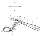
以下、本発明の一実施形態について、図面を参照して説明する。図1に示すように、ヘッドマウントディスプレイ(Head Mounted Display、以下、「HMD」という。)1は、光学透過型のシースルーHMDである。使用者の眼前の景色の光は、ハーフミラー51を透過することによって使用者の眼に直接導かれる。HMD1の投影形式は、虚像投影型である。ハーフミラー51は、液晶パネル562(図8参照、後述)に表示された画像の光を、使用者の片側の眼に向けて反射させる。HMD1は、使用者に対して、眼前の景色に画像を重ねて認識させることができる。HMD1は、装着具8、接続具9、及び、画像表示装置11を備える。以下、図の説明の理解を助けるため、画像表示装置11の上側、下側、左側、右側、前側、及び、後側を定義する。画像表示装置11の上側、下側、左側、及び、右側は、例えば、図1の上側、下側、左側、及び、右側にそれぞれ対応する。画像表示装置11の前側、及び、後側は、例えば、図3の上側、及び、下側にそれぞれ対応する。画像表示装置11の上側、下側、左側、右側、前側、及び、後側は、それぞれ、装着具8が着用された使用者にとって、上側、下側、右側、左側、前側、及び、後側に対応する。   Hereinafter, an embodiment of the present invention will be described with reference to the drawings. As shown in FIG. 1, a head mounted display (hereinafter referred to as “HMD”) 1 is an optically transmissive see-through HMD. The light of the scenery in front of the user's eyes is guided directly to the user's eyes by passing through the half mirror 51. The projection format of HMD1 is a virtual image projection type. The half mirror 51 reflects the light of the image displayed on the liquid crystal panel 562 (see FIG. 8, described later) toward one eye of the user. The HMD 1 can allow the user to recognize an image superimposed on the scene in front of him. The HMD 1 includes a mounting tool 8, a connection tool 9, and an image display device 11. Hereinafter, in order to help understand the description of the figure, the upper side, lower side, left side, right side, front side, and rear side of the image display device 11 are defined. The upper side, the lower side, the left side, and the right side of the image display device 11 correspond to, for example, the upper side, the lower side, the left side, and the right side of FIG. The front side and the rear side of the image display device 11 correspond to, for example, the upper side and the lower side in FIG. The upper side, the lower side, the left side, the right side, the front side, and the rear side of the image display device 11 are the upper side, the lower side, the right side, the left side, the front side, and the rear side, respectively, for the user wearing the wearing tool 8. Corresponding to

<装着具8>
図1、図2、図3に示すように、装着具8は、樹脂や金属(例えば、ステンレス)などの、可撓性を有する材質で構成される。装着具8は、第1部分81及び第2部分82、83を有する。なお、以下では、理解を容易とするために、装着具8を第1部分81及び第2部分82、83に区分して説明するが、装着具8は、第1部分81及び第2部分82、83のそれぞれの部材に分かれておらず、全体として一体の部材である。
<Mounting tool 8>
As shown in FIGS. 1, 2, and 3, the mounting tool 8 is made of a flexible material such as resin or metal (for example, stainless steel). The mounting tool 8 includes a first portion 81 and second portions 82 and 83. In the following, for ease of understanding, the mounting tool 8 will be described as being divided into a first part 81 and second parts 82 and 83. However, the mounting tool 8 includes the first part 81 and the second part 82. , 83 are not divided into individual members, but are integral members as a whole.

第1部分81及び第2部分82、83は、それぞれ、湾曲した細長い板状部材である。第1部分81は、装着具8のうち、位置8Aと位置8Bとの間で左右方向に延びる部分である。第1部分81は、前側に凸状に湾曲する。位置8Aは、装着具8の左右方向中心84よりも左側、且つ、前後方向中心85(図2参照)よりも前側に位置する。位置8Bは、装着具8の左右方向中心84よりも右側、且つ、前後方向中心85(図2参照)よりも前側に位置する。第2部分82は、装着具8のうち、位置8Aから後側に延びる部分である。第2部分83は、装着具8のうち、位置8Bから後側に延びる部分である。第2部分82、83は、それぞれ、後端部が互いに近づく方向に延びる。装着具8は、使用者の前頭部、右側頭部、及び、左側頭部のそれぞれに、第1部分81、第2部分82、83を接触させた状態で、使用者の頭部に着用される。この状態で、第1部分81は使用者の額に沿って左右方向に延びる。以下、装着具8のうち第1部分81及び第2部分82、83で囲まれた側を、「装着具8の内側」といい、装着具8の内側と反対側を、「装着具8の外側」という。   The first portion 81 and the second portions 82 and 83 are each curved and elongated plate-like members. The first portion 81 is a portion of the wearing tool 8 that extends in the left-right direction between the position 8A and the position 8B. The first portion 81 is curved in a convex shape on the front side. The position 8A is located on the left side of the center 84 in the left-right direction and on the front side of the center 85 in the front-rear direction (see FIG. 2). The position 8B is located on the right side of the left / right center 84 of the wearing tool 8 and on the front side of the front / rear direction center 85 (see FIG. 2). The second portion 82 is a portion of the wearing tool 8 that extends rearward from the position 8A. The second portion 83 is a portion of the wearing tool 8 that extends rearward from the position 8B. The second portions 82 and 83 each extend in a direction in which the rear ends approach each other. The wearing tool 8 is worn on the user's head with the first portion 81 and the second portions 82 and 83 in contact with the frontal, right and left heads of the user, respectively. Is done. In this state, the first portion 81 extends in the left-right direction along the user's forehead. Hereinafter, the side surrounded by the first portion 81 and the second portions 82 and 83 of the mounting tool 8 is referred to as “the inner side of the mounting tool 8”, and the side opposite to the inner side of the mounting tool 8 is referred to as “the mounting tool 8. It is called “outside”.

図1に示すように、第1部分81は、外側と内側との間を貫通する2つの穴部81Aを、位置8Aの前側に有する。第1部分81は、外側と内側との間を貫通する2つの穴部81B(図5参照)を、位置8Bの前側に有する。後述する接続部材7は、2つの穴部81Bを覆う位置に接続される。なお、接続部材7は、2つの穴部81Aを覆う位置に接続することも可能である。   As shown in FIG. 1, the first portion 81 has two holes 81 </ b> A penetrating between the outer side and the inner side on the front side of the position 8 </ b> A. The first portion 81 has two holes 81B (see FIG. 5) penetrating between the outer side and the inner side on the front side of the position 8B. The connecting member 7 described later is connected to a position that covers the two holes 81B. The connecting member 7 can also be connected to a position covering the two hole portions 81A.

<接続具9>
図4に示すように、接続具9は略棒状である。接続具9は、樹脂や金属などで構成される。接続具9は、正面から見た状態で上下方向に延びる。より詳細には、図2に示すように、接続具9は上下方向に対して下端部が前方に傾斜する向きに延びる。図3、図4に示すように、接続具9は、板状の第1壁部9A及び第2壁部9Bを有する。第1壁部9Aの面積の最も大きい一対の平面のそれぞれは、左右方向を向く。図2に示すように、第1壁部9Aは、左右方向に貫通する穴9Cを有する。穴9Cは、上下方向に長い長穴である。図3に示すように、第2壁部9Bは、第1壁部9Aの前端部、後端部、上端部、及び、下端部のそれぞれから左方向に向けて、湾曲しながら延びる。
<Connector 9>
As shown in FIG. 4, the connection tool 9 is substantially rod-shaped. The connection tool 9 is made of resin or metal. The connection tool 9 extends in the vertical direction as viewed from the front. More specifically, as shown in FIG. 2, the connector 9 extends in a direction in which the lower end portion is inclined forward with respect to the vertical direction. As shown in FIGS. 3 and 4, the connector 9 includes a plate-like first wall portion 9 </ b> A and a second wall portion 9 </ b> B. Each of the pair of planes having the largest area of the first wall portion 9A faces in the left-right direction. As shown in FIG. 2, the first wall portion 9A has a hole 9C penetrating in the left-right direction. The hole 9C is a long hole that is long in the vertical direction. As shown in FIG. 3, the second wall portion 9B extends while curving from the front end portion, the rear end portion, the upper end portion, and the lower end portion of the first wall portion 9A in the left direction.

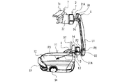
接続具9の上端部は、後述する第1ボールジョイント2及び接続部材7を介して装着具8に接続される。接続具9の下端部は、後述する第2ボールジョイント3及び接続部材6を介して画像表示装置11に接続される。画像表示装置11は、接続具9によって装着具8に取り付けられる。接続具9は、装着具8から離隔した位置に画像表示装置11を保持する。接続具9は、装着具8が使用者の頭部に着用された状態で、画像表示装置11のハーフミラー51を、使用者の左眼の前方に配置させることができる。   The upper end portion of the connection tool 9 is connected to the mounting tool 8 via a first ball joint 2 and a connection member 7 described later. A lower end portion of the connection tool 9 is connected to the image display device 11 via a second ball joint 3 and a connection member 6 described later. The image display device 11 is attached to the mounting tool 8 by the connecting tool 9. The connection tool 9 holds the image display device 11 at a position separated from the mounting tool 8. The connection tool 9 can place the half mirror 51 of the image display device 11 in front of the left eye of the user in a state where the mounting tool 8 is worn on the user's head.

<接続部材7>
図1、図3に示すように、接続部材7は、連結部71及び円柱部72を有する。連結部71は、装着具8の内側、外側、及び、上側のそれぞれに接触する(図5参照)。連結部71は、装着具8に対して接続部材7を着脱可能に連結する。図5に示すように、連結部71は、2つの穴部81Bに内側から挿通する2つのねじ71Aによって、装着具8に固定される。図1、図3に示すように、円柱部72は円柱状の部材である。円柱部72は、連結部71のうち装着具8の外側に接触する部分から、右側に突出する。図3に示すように、円柱部72の中心軸は、左右方向と平行に延びる。円柱部72の直径は、装着具8のうち2つの穴部81Bが設けられた部分の上下方向の幅と略同一である。円柱部72の右端に、後述する第1ボールジョイント2の第1ソケット22が接続する。
<Connection member 7>
As shown in FIGS. 1 and 3, the connecting member 7 has a connecting portion 71 and a columnar portion 72. The connection part 71 contacts each of the inner side, the outer side, and the upper side of the wearing tool 8 (see FIG. 5). The connection part 71 connects the connection member 7 to the mounting tool 8 so as to be detachable. As shown in FIG. 5, the connecting portion 71 is fixed to the mounting tool 8 by two screws 71A that are inserted through the two hole portions 81B from the inside. As shown in FIGS. 1 and 3, the cylindrical portion 72 is a cylindrical member. The cylindrical portion 72 protrudes to the right from the portion of the connecting portion 71 that contacts the outside of the wearing tool 8. As shown in FIG. 3, the central axis of the cylindrical portion 72 extends in parallel with the left-right direction. The diameter of the cylindrical portion 72 is substantially the same as the width in the vertical direction of the portion of the mounting tool 8 where the two hole portions 81B are provided. A first socket 22 of the first ball joint 2 described later is connected to the right end of the cylindrical portion 72.

<第1ボールジョイント2>
図5に示すように、第1ボールジョイント2は、第1ボールスタッド21、及び、第1ソケット22を備えている。第1ボールスタッド21は、第1棒部21A及び第1球体部21Bを有する。第1棒部21Aは棒状の部位である。第1棒部21Aは、左右方向に直線状に延びる。図4に示すように、円筒状の嵌合部91が、接続具9の第1壁部9Aの上端部の左側面に設けられる。第1棒部21Aの右端部は、嵌合部91の内側に嵌る。嵌合部91の円筒中心を通る軸は、第1壁部9Aに対して直交する。嵌合部91は、第1壁部9Aから左方向に延びる。第1棒部21Aは、接続具9の第1壁部9Aから左方向に延びた状態で、接続具9に固定される。第1棒部21Aは、第1壁部9Aに対して略直交する。第1球体部21Bは、第1棒部21Aの左端部に設けられた球状の部位である。以下、第1球体部21Bの直径をr1と表記する。r1は、第1棒部21Aの左右方向と直交する断面の径よりも大きい。
<First ball joint 2>
As shown in FIG. 5, the first ball joint 2 includes a first ball stud 21 and a first socket 22. The first ball stud 21 has a first rod portion 21A and a first sphere portion 21B. The first rod portion 21A is a rod-shaped part. The first rod portion 21A extends linearly in the left-right direction. As shown in FIG. 4, a cylindrical fitting portion 91 is provided on the left side surface of the upper end portion of the first wall portion 9 </ b> A of the connection tool 9. The right end portion of the first rod portion 21 </ b> A is fitted inside the fitting portion 91. An axis passing through the cylindrical center of the fitting portion 91 is orthogonal to the first wall portion 9A. The fitting portion 91 extends leftward from the first wall portion 9A. The first bar portion 21 </ b> A is fixed to the connection tool 9 in a state of extending in the left direction from the first wall portion 9 </ b> A of the connection tool 9. The first rod portion 21A is substantially orthogonal to the first wall portion 9A. The first sphere portion 21B is a spherical portion provided at the left end portion of the first rod portion 21A. Hereinafter, the diameter of the first sphere portion 21B is denoted as r1. r1 is larger than the diameter of the cross section orthogonal to the left-right direction of the first rod portion 21A.

図5に示すように、第1ソケット22は、第1蓋部221及び第1受け部222を有する。第1受け部222は、底部222A、側部222B、及び、第1接触部222Cを有する。底部222Aは、接続部材7の円柱部72の右端に接触する円形板状の部位である。底部222Aの面積の最も大きい一対の平面のそれぞれは、左右方向を向く。底部222Aの直径は、円柱部72の直径と略同一である。底部222Aの左側面に、左方向に突出する突出部222Dが設けられる。突出部222Dの左側面に、右方向に延びるねじ穴が設けられる。底部222Aは、ねじ穴に螺入するねじ71Bによって、円柱部72に固定される。   As shown in FIG. 5, the first socket 22 includes a first lid portion 221 and a first receiving portion 222. The first receiving part 222 has a bottom part 222A, a side part 222B, and a first contact part 222C. The bottom portion 222 </ b> A is a circular plate-shaped portion that contacts the right end of the columnar portion 72 of the connection member 7. Each of the pair of planes having the largest area of the bottom portion 222A faces in the left-right direction. The diameter of the bottom portion 222A is substantially the same as the diameter of the cylindrical portion 72. A protruding portion 222D protruding leftward is provided on the left side surface of the bottom portion 222A. A screw hole extending in the right direction is provided on the left side surface of the protrusion 222D. The bottom portion 222A is fixed to the cylindrical portion 72 by a screw 71B that is screwed into the screw hole.

側部222Bは、底部222Aの左右方向と直交する方向の端部から右方向に延びる、筒状の部位である。側部222Bの外側の面にはねじ山が形成されている。側部222Bで囲まれた部分に、第1接触部222Cが配置されている。第1接触部222Cは、緩衝材として機能する弾性変形可能なゴムである。第1接触部222Cは、第1ボールスタッド21の第1球体部21Bの左側の部分に接触する。   The side portion 222B is a cylindrical portion that extends rightward from an end portion of the bottom portion 222A in a direction orthogonal to the left-right direction. A thread is formed on the outer surface of the side portion 222B. The first contact portion 222C is disposed in a portion surrounded by the side portion 222B. The first contact portion 222C is an elastically deformable rubber that functions as a cushioning material. The first contact portion 222 </ b> C contacts the left portion of the first sphere portion 21 </ b> B of the first ball stud 21.

第1蓋部221は、底部221A、側部221B、及び、第1接触部221Cを有する。底部221Aは、円形板状の部位である。底部221Aの面積の最も大きい一対の平面のそれぞれは、左右方向を向く。底部221Aの直径は、第1受け部222の側部222Bの外径よりも僅かに大きい。底部221Aは、左右方向に貫通する円形の第1穴部221Dを中心に有する。第1穴部221Dの直径は、第1棒部21Aの左右方向と直交する断面の径よりも大きく、第1ボールスタッド21の第1球体部21Bの直径であるr1よりも小さい。第1ボールスタッド21の第1棒部21Aは、第1穴部221Dを左右方向に貫通する。第1球体部21Bは、第1穴部221Dの左側に配置される。以下、第1ボールジョイント2において、第1ボールスタッド21の第1棒部21Aが、第1穴部221Dの円周の中心を貫通した状態を、「第1中立状態」という。   The first lid part 221 has a bottom part 221A, a side part 221B, and a first contact part 221C. The bottom 221A is a circular plate-shaped part. Each of the pair of planes having the largest area of the bottom 221A faces in the left-right direction. The diameter of the bottom portion 221A is slightly larger than the outer diameter of the side portion 222B of the first receiving portion 222. The bottom 221A has a circular first hole 221D that penetrates in the left-right direction. The diameter of the first hole portion 221D is larger than the diameter of the cross section orthogonal to the left-right direction of the first rod portion 21A, and smaller than r1 which is the diameter of the first spherical portion 21B of the first ball stud 21. The first rod portion 21A of the first ball stud 21 penetrates the first hole portion 221D in the left-right direction. The first sphere part 21B is disposed on the left side of the first hole part 221D. Hereinafter, in the first ball joint 2, the state in which the first rod portion 21A of the first ball stud 21 penetrates the center of the circumference of the first hole portion 221D is referred to as a “first neutral state”.

第1棒部21A及び第1球体部21Bと第1穴部221Dとの間の隙間に、第1接触部221Cが配置されている。第1接触部221Cは、緩衝材として機能する弾性変形可能なゴムである。第1接触部221Cは、第1球体部21Bの右側の部分に接触する。   The first contact portion 221C is disposed in the gap between the first rod portion 21A and the first sphere portion 21B and the first hole portion 221D. The first contact portion 221C is an elastically deformable rubber that functions as a cushioning material. The first contact portion 221C contacts the right portion of the first sphere portion 21B.

側部221Bは、底部221Aの左右方向と直交する方向の端部から左方向に延びる、筒状の部位である。側部221Bの内側の面にねじ山が形成されている。側部221Bのねじ山は、第1受け部222の側部222Bのねじ山に嵌る。これによって、第1蓋部221は第1受け部222に螺合する。以下、側部221Bの内径を第1直径といい、R1と表記する。第1蓋部221が第1受け部222に螺合する過程で、第1蓋部221は接続具9側から装着具8側に向けて、矢印24の方向に移動する。第1球体部21Bは、第1蓋部221と第1受け部222とで囲まれた空間内に配置される。第1接触部221C、222Cは、第1球体部21Bを左右方向両側から挟む。   The side portion 221B is a cylindrical portion that extends in the left direction from the end portion of the bottom portion 221A in the direction orthogonal to the left-right direction. A thread is formed on the inner surface of the side portion 221B. The thread of the side part 221B fits into the thread of the side part 222B of the first receiving part 222. As a result, the first lid portion 221 is screwed into the first receiving portion 222. Hereinafter, the inner diameter of the side portion 221B is referred to as a first diameter and is denoted as R1. In the process in which the first lid portion 221 is screwed into the first receiving portion 222, the first lid portion 221 moves in the direction of the arrow 24 from the connection tool 9 side toward the mounting tool 8 side. The first sphere part 21 </ b> B is disposed in a space surrounded by the first lid part 221 and the first receiving part 222. The first contact portions 221C and 222C sandwich the first sphere portion 21B from both sides in the left-right direction.

第1球体部21Bは、第1接触部221C、222Cに対して摺動することによって、任意の方向に回転可能である。このため、第1ボールジョイント2は、装着具8に対して接続具9を、任意の方向に回転させることができる。なお、第1球体部21Bから第1棒部21Aが延びる方向は、第1棒部21Aを支点として第1球体部21Bが回転する場合を除いて、第1球体部21Bの回転に応じて変化する。第1棒部21Aの延びる方向の変化可能な範囲は、第1接触部221Cに第1棒部21Aが接触することよって制限される。これによって、第1球体部21Bが回転するときの回転可能な範囲は規制される。   The first sphere portion 21B can rotate in any direction by sliding with respect to the first contact portions 221C and 222C. For this reason, the first ball joint 2 can rotate the connection tool 9 in an arbitrary direction with respect to the mounting tool 8. Note that the direction in which the first rod portion 21A extends from the first sphere portion 21B changes according to the rotation of the first sphere portion 21B, except when the first sphere portion 21B rotates with the first rod portion 21A as a fulcrum. To do. The changeable range of the extending direction of the first rod portion 21A is limited by the contact of the first rod portion 21A with the first contact portion 221C. Accordingly, the rotatable range when the first sphere 21B rotates is restricted.

以下、第1ボールジョイント2が第1中立状態のときに、第1棒部21Aに沿って延びる回転軸86Aを定義する。回転軸86Aは、第1球体部21Bの中心21Cと、第1穴部221Dの円周の中心211Eとを結ぶ方向に沿って延びる線分に対応する。装着具8の外側の面のうち、第1中立状態における回転軸86Aとの交点を、連結部86と定義する。装着具8の連結部86における法線86Cを定義する。この場合、第1中立状態における回転軸86Aは、前後方向、上下方向、及び、法線86Cのいずれとも交差する。   Hereinafter, when the first ball joint 2 is in the first neutral state, a rotation shaft 86A extending along the first rod portion 21A is defined. The rotation shaft 86A corresponds to a line segment extending along the direction connecting the center 21C of the first sphere 21B and the center 211E of the circumference of the first hole 221D. Of the outer surface of the mounting tool 8, an intersection with the rotation shaft 86 </ b> A in the first neutral state is defined as a connecting portion 86. A normal 86 </ b> C at the connecting portion 86 of the mounting tool 8 is defined. In this case, the rotation shaft 86A in the first neutral state intersects with any of the front-rear direction, the vertical direction, and the normal line 86C.

第1受け部222に対する第1蓋部221の螺合の程度、言い換えれば、第1受け部222の底部222Aと、第1蓋部221の底部221Aとの距離に応じて、第1接触部221C、222Cが第1球体部21Bに押し付けられる力は変化する。底部222Aに対して底部221Aが近接する程、第1球体部21Bに第1接触部221C、222Cが押し付けられる力も大きくなる。この場合、第1球体部21Bと第1接触部221C、222Cとの間の静トルクは大きくなる。なお、第1球体部21Bと第1接触部221C、222Cとの間の静トルクは、装着具8に対して接続具9の延びる方向を変化させる場合に第1ボールジョイント2によって接続具9を保持可能なトルクに対応する。このため使用者は、第1受け部222に対する第1蓋部221の螺合の程度を調整することによって、第1球体部21Bと第1接触部221C、222Cとの間の静トルクを調整できる。以下、第1球体部21Bと第1接触部221C、222Cとの間の静トルクを、F1(単位:N・m)と表記する。   The first contact portion 221C depends on the degree of screwing of the first lid portion 221 to the first receiving portion 222, in other words, the distance between the bottom portion 222A of the first receiving portion 222 and the bottom portion 221A of the first lid portion 221. , 222C is pressed against the first sphere 21B. The closer the bottom 221A is to the bottom 222A, the greater the force with which the first contact portions 221C and 222C are pressed against the first sphere 21B. In this case, the static torque between the first sphere portion 21B and the first contact portions 221C and 222C increases. Note that the static torque between the first sphere portion 21B and the first contact portions 221C, 222C causes the connecting tool 9 to be moved by the first ball joint 2 when the extending direction of the connecting tool 9 is changed with respect to the mounting tool 8. Corresponds to the torque that can be held. For this reason, the user can adjust the static torque between the first spherical body portion 21B and the first contact portions 221C and 222C by adjusting the degree of screwing of the first lid portion 221 to the first receiving portion 222. . Hereinafter, the static torque between the first sphere portion 21B and the first contact portions 221C and 222C is expressed as F1 (unit: N · m).

<画像表示装置11>
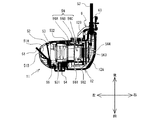
図6、図7、図8に示すように、画像表示装置11は筐体12を備えている。筐体12は、本体部12Aと突出部12Bとを有する。本体部12Aは、角が湾曲した略直方体状の形状を有する。突出部12Bは、本体部12Aの右後側から後方に突出する。筐体12は中空箱状である。本体部12Aの左側は開放し、筐体12内部のレンズユニット53(図8参照)の左側は露出する。図1に示すように、左端部121は、本体部12Aの前面における左端部分に設けられる。左端部121は、上下方向両端部から上下方向中心に向けて、右方に凹む。左端部121は略円弧を形成する。図7に示すように、左端部122は、本体部12Aの後面における左端部分に設けられる。左端部122は右方に凹む。図6、図7に示すように、本体部12Aの後面、且つ、左右方向中心よりも右側に、接続部材6が接続されている。接続部材6の詳細は後述する。突出部12Bの後端から後方に向けて延びる通信線57は、信号線、電力線、及び、被覆を有する。信号線は、制御用のデータを伝達可能な導線である。電力線は、電力を伝達可能な導線である。被覆は、信号線及び電力線の絶縁及び保護のために、信号線及び電力線の周囲を覆っている。突出部12Bには、通信線57が挿入されている。HMD1は、外部機器(図示略)と通信線57を介して接続される。外部機器は、通信線57の信号線を介して、HMD1に画像データを出力する。
<Image display device 11>
As shown in FIGS. 6, 7, and 8, the image display device 11 includes a housing 12. The housing 12 includes a main body portion 12A and a protruding portion 12B. The main body 12A has a substantially rectangular parallelepiped shape with curved corners. The protrusion 12B protrudes rearward from the right rear side of the main body 12A. The housing 12 has a hollow box shape. The left side of the main body 12A is opened, and the left side of the lens unit 53 (see FIG. 8) inside the housing 12 is exposed. As shown in FIG. 1, the left end 121 is provided at the left end of the front surface of the main body 12A. The left end 121 is recessed rightward from the both ends in the vertical direction toward the center in the vertical direction. The left end 121 forms a substantially arc. As shown in FIG. 7, the left end 122 is provided at the left end of the rear surface of the main body 12A. The left end 122 is recessed to the right. As shown in FIGS. 6 and 7, the connecting member 6 is connected to the rear surface of the main body 12 </ b> A and on the right side of the center in the left-right direction. Details of the connection member 6 will be described later. The communication line 57 extending rearward from the rear end of the protruding portion 12B has a signal line, a power line, and a coating. The signal line is a conducting wire capable of transmitting control data. A power line is a conducting wire capable of transmitting power. The covering covers the periphery of the signal line and the power line for insulation and protection of the signal line and the power line. A communication line 57 is inserted into the protruding portion 12B. The HMD 1 is connected to an external device (not shown) via a communication line 57. The external device outputs image data to the HMD 1 via the signal line of the communication line 57.

図8に示すように、筐体12内に、レンズユニット53、調節機構55、及び、画像光ユニット56が配置される。ホルダ52は、筐体12の本体部12Aの左端部に保持される。ホルダ52はハーフミラー51を支持する。ハーフミラー51、ホルダ52、レンズユニット53、及び、画像光ユニット56は、左側から右側に向けて順番に並ぶ。調節機構55は、レンズユニット53の前側に配置される。図1に示すように、操作部材54は、本体部12Aの前面、且つ、左右方向中心よりも左側に設けられる。操作部材54は、本体部12Aの前面を挟んで調節機構55の前側に配置される。   As shown in FIG. 8, the lens unit 53, the adjustment mechanism 55, and the image light unit 56 are disposed in the housing 12. The holder 52 is held at the left end of the main body 12 </ b> A of the housing 12. The holder 52 supports the half mirror 51. The half mirror 51, the holder 52, the lens unit 53, and the image light unit 56 are arranged in order from the left side to the right side. The adjustment mechanism 55 is disposed on the front side of the lens unit 53. As shown in FIG. 1, the operation member 54 is provided on the front surface of the main body 12A and on the left side of the center in the left-right direction. The operation member 54 is disposed on the front side of the adjustment mechanism 55 with the front surface of the main body 12A interposed therebetween.

画像光ユニット56は、通信線57の信号線を介して外部機器から受信する。画像光ユニット56は、受信した画像データに応じた画像の画像光を生成し、射出する。画像光ユニット56は、第1保持部材56A、液晶表示装置56B、及び、第2保持部材56Cを有する。第1保持部材56Aは、左右方向に延びる円筒状の部材である。第1保持部材56Aは、筐体12に対する固定的な位置に保持される。液晶表示装置56Bは、ガラス基板561及び液晶パネル562を有する。ガラス基板561及び液晶パネル562は、第1保持部材56Aの右側に設けられる。液晶パネル562は矩形状の周知の液晶パネルである。液晶パネル562は、左側面に画像を表示させることによって、画像光を生成する。ガラス基板561は、液晶パネル562の左側面に設けられ、液晶パネル562の表示面を保護する。例えば、液晶パネル562が反射型液晶の場合、ガラス基板561によって導かれた光源(非図示)からの光が、液晶パネル562に入射する。液晶パネル562は、入射した光を反射することで、画像光を生成する。液晶パネル562によって生成された画像光は、ガラス基板561を左側に透過する。第2保持部材56Cは、基板保持部分563及び制御基板564を有する。基板保持部分563は、液晶表示装置56Bの液晶パネル562の右側に配置される。制御基板564は、基板保持部分563の右側に保持される。制御基板564は、フレキシブルプリント基板(図示略)を介して液晶パネル562に接続される。制御基板564に通信線57の信号線が接続される。制御基板564は、外部機器から送信された画像データを、通信線57の信号線を介して受信する。制御基板564は、フレキシブルプリント基板を介して液晶パネル562に制御信号を出力することによって、画像データに応じた画像を液晶パネル562に表示させる。   The image light unit 56 receives from an external device via the signal line of the communication line 57. The image light unit 56 generates and emits image light of an image according to the received image data. The image light unit 56 includes a first holding member 56A, a liquid crystal display device 56B, and a second holding member 56C. The first holding member 56A is a cylindrical member extending in the left-right direction. The first holding member 56 </ b> A is held at a fixed position with respect to the housing 12. The liquid crystal display device 56B includes a glass substrate 561 and a liquid crystal panel 562. The glass substrate 561 and the liquid crystal panel 562 are provided on the right side of the first holding member 56A. The liquid crystal panel 562 is a well-known rectangular liquid crystal panel. The liquid crystal panel 562 generates image light by displaying an image on the left side surface. The glass substrate 561 is provided on the left side surface of the liquid crystal panel 562 and protects the display surface of the liquid crystal panel 562. For example, when the liquid crystal panel 562 is a reflective liquid crystal, light from a light source (not shown) guided by the glass substrate 561 enters the liquid crystal panel 562. The liquid crystal panel 562 generates image light by reflecting incident light. The image light generated by the liquid crystal panel 562 passes through the glass substrate 561 to the left side. The second holding member 56C has a substrate holding portion 563 and a control substrate 564. The substrate holding portion 563 is disposed on the right side of the liquid crystal panel 562 of the liquid crystal display device 56B. The control board 564 is held on the right side of the board holding portion 563. The control board 564 is connected to the liquid crystal panel 562 via a flexible printed board (not shown). The signal line of the communication line 57 is connected to the control board 564. The control board 564 receives the image data transmitted from the external device via the signal line of the communication line 57. The control board 564 causes the liquid crystal panel 562 to display an image corresponding to the image data by outputting a control signal to the liquid crystal panel 562 via the flexible printed board.

なお、本発明において、液晶パネル562の代わりに、Digital Mirror Device(DMD)、有機EL等の二次元表示装置が用いられてもよい。更に、2次元的に走査された光を使用者の網膜上に投影する網膜走査型の投影装置(Retinal Scanning Display)が用いられてもよい。   In the present invention, a two-dimensional display device such as a digital mirror device (DMD) or an organic EL may be used instead of the liquid crystal panel 562. Furthermore, a retinal scanning type projection device (Retinal Scanning Display) that projects light two-dimensionally scanned onto the retina of the user may be used.

レンズユニット53は、画像光ユニット56の左側に配置される。レンズユニット53は、画像光ユニット56から射出された画像光を、レンズユニット53の左側に配置されたハーフミラー51に導く。レンズユニット53は、略四角筒状の保持部材531を有する。保持部材531は、筐体12の内壁に対して左右方向に摺動可能に保持される。保持部材531の内側に、複数のレンズ532が固定されている。複数のレンズ532のそれぞれの光軸は、保持部材531の中心を左右方向に延びる軸線上に配置されている。画像光ユニット56によって生成された画像光は、保持部材531の内部に右側から入射し、保持部材531の左端から左側に向けて射出する。複数のレンズ532は、右側から入射する画像光を屈折させ、左側に出射させる。保持部材531の前側の面に、前方に向けて突出する図示外の凸部が設けられる。凸部は、後述する調節機構55の図示外のカム溝に嵌る。レンズユニット53は、左右方向に移動可能である。   The lens unit 53 is disposed on the left side of the image light unit 56. The lens unit 53 guides the image light emitted from the image light unit 56 to the half mirror 51 disposed on the left side of the lens unit 53. The lens unit 53 includes a holding member 531 having a substantially square cylindrical shape. The holding member 531 is held so as to be slidable in the left-right direction with respect to the inner wall of the housing 12. A plurality of lenses 532 are fixed inside the holding member 531. Each optical axis of the plurality of lenses 532 is disposed on an axis extending in the left-right direction at the center of the holding member 531. The image light generated by the image light unit 56 enters the holding member 531 from the right side, and exits from the left end of the holding member 531 toward the left side. The plurality of lenses 532 refracts image light incident from the right side and emits it to the left side. On the front surface of the holding member 531, a convex portion (not shown) that projects forward is provided. The convex portion fits into a cam groove (not shown) of the adjusting mechanism 55 described later. The lens unit 53 is movable in the left-right direction.

操作部材54は円錐台状の部材である。操作部材54の中心軸は、前後方向に延びる。操作部材54は、中心軸を中心として回動可能である。調節機構55は円形板状の部材である。調節機構55の最も大きい一対の平面のそれぞれは、前後方向を向く。調節機構55は、前方に配置された操作部材54に接続する。調節機構55の後側面に図示外のカム溝が設けられる。カム溝には、レンズユニット53の保持部材531の図示外の凸部が、後方から嵌る。調節機構55は、円形中心を通って前後方向に延びる軸を中心として、操作部材54と一体となって回転可能である。操作部材54が回転した場合、調節機構55のカム溝は、レンズユニットの保持部材531の凸部を左右方向に移動させる。レンズユニット53は、操作部材54の回転に応じて左右方向に移動する。使用者は、操作部材54を回転させることによって、HMD1のピント調節を行うことができる。   The operation member 54 is a frustoconical member. The central axis of the operation member 54 extends in the front-rear direction. The operation member 54 can rotate around the central axis. The adjustment mechanism 55 is a circular plate member. Each of the largest pair of planes of the adjusting mechanism 55 faces in the front-rear direction. The adjustment mechanism 55 is connected to the operation member 54 disposed on the front side. A cam groove (not shown) is provided on the rear side surface of the adjusting mechanism 55. A convex portion (not shown) of the holding member 531 of the lens unit 53 is fitted into the cam groove from behind. The adjustment mechanism 55 can rotate integrally with the operation member 54 around an axis extending in the front-rear direction through the circular center. When the operation member 54 rotates, the cam groove of the adjustment mechanism 55 moves the convex part of the holding member 531 of the lens unit in the left-right direction. The lens unit 53 moves in the left-right direction according to the rotation of the operation member 54. The user can adjust the focus of the HMD 1 by rotating the operation member 54.

ホルダ52は、レンズユニット53の左側に配置される。ホルダ52は、筐体12に対して着脱可能である。ホルダ52はハーフミラー51を支持する。ハーフミラー51は、レンズユニット53の左側に配置される。ハーフミラー51は矩形板状である。ハーフミラー51の両面のうち一方の面51Aは、右斜め後方を向く。ハーフミラー51の両面のうち他方の面51Bは、左斜め前方を向く。ハーフミラー51は、面51A側、及び、面51B側から入射した光の一部(例えば50%)を反射させ、他部を透過させることができる。ハーフミラー51は、レンズユニット53を通過して右側から入射する画像光を後側に反射させることができる。使用者の眼は、ハーフミラー51によって後側に反射された画像光に基づいて、虚像を視認できる。又、ハーフミラー51は、面51B側からから入射した外界の光を、後側に透過させることができる。ハーフミラー51は、例えば、透明な樹脂やガラスの基板上に、アルミや銀などの金属を所定の反射率(例えば50%)となるように蒸着することで構成される。   The holder 52 is disposed on the left side of the lens unit 53. The holder 52 is detachable from the housing 12. The holder 52 supports the half mirror 51. The half mirror 51 is disposed on the left side of the lens unit 53. The half mirror 51 has a rectangular plate shape. One surface 51 </ b> A of both surfaces of the half mirror 51 faces obliquely rearward to the right. Of the both surfaces of the half mirror 51, the other surface 51B faces diagonally to the left. The half mirror 51 can reflect a part (for example, 50%) of light incident from the surface 51A side and the surface 51B side and transmit the other part. The half mirror 51 can reflect the image light that passes through the lens unit 53 and enters from the right side to the rear side. The user's eyes can visually recognize the virtual image based on the image light reflected to the rear side by the half mirror 51. Further, the half mirror 51 can transmit light from the outside that is incident from the surface 51B side to the rear side. The half mirror 51 is configured, for example, by depositing a metal such as aluminum or silver on a transparent resin or glass substrate so as to have a predetermined reflectance (for example, 50%).

なお、本発明において、上記のハーフミラー51の代わりに、面51A側から入射した画像光を左側に反射させない反射部材が用いられてもよい。この場合、面51B側から入射した光は、反射部材を透過しない。又、ハーフミラー51の代わりに、プリズムや回折格子のような光路偏向部材が用いられてもよい。   In the present invention, instead of the half mirror 51, a reflection member that does not reflect the image light incident from the surface 51A side to the left side may be used. In this case, the light incident from the surface 51B side does not pass through the reflecting member. Further, instead of the half mirror 51, an optical path deflecting member such as a prism or a diffraction grating may be used.

<接続部材6>
図6、図7に示すように、接続部材6は、画像表示装置11と、後述する第2ボールジョイント3とを接続する。図8では、第2ボールジョイント3は省略されている。図6、図7、図9に示すように、接続部材6は、支持部61、62、63を有する。支持部61は円形板状である。支持部61のもっとも面積の大きい一対の平面のそれぞれは、前後方向を向く。支持部61の直径は、画像表示装置11の筐体12の後面の上下方向の長さよりも短い(図7参照)。支持部61は、左右方向に並んだ複数の穴部611を有する(図7、図9参照)。接続部材6は、複数の穴部611に後側から挿通する図示外のねじによって、筐体12の後面に固定される。
<Connection member 6>
As shown in FIGS. 6 and 7, the connecting member 6 connects the image display device 11 and a second ball joint 3 described later. In FIG. 8, the second ball joint 3 is omitted. As shown in FIGS. 6, 7, and 9, the connection member 6 includes support portions 61, 62, and 63. The support part 61 has a circular plate shape. Each of the pair of planes having the largest area of the support portion 61 faces in the front-rear direction. The diameter of the support part 61 is shorter than the length of the rear surface of the housing 12 of the image display device 11 in the vertical direction (see FIG. 7). The support 61 has a plurality of holes 611 arranged in the left-right direction (see FIGS. 7 and 9). The connection member 6 is fixed to the rear surface of the housing 12 by screws (not shown) that are inserted into the plurality of holes 611 from the rear side.

図7、図9に示すように、支持部62は、第1支持部62A及び第2支持部62Bを有する。第1支持部62Aは、支持部61の右端部から後方に延びる。図7に示すように、第1支持部62Aの前後方向の長さは、画像表示装置11の筐体12の突出部12Bの前後方向の長さよりも僅かに長い。第2支持部62Bは、第1支持部62Aの後端から右方に延びる。第2支持部62Bは、突出部12Bの後方を通過する。第2支持部62Bは、前後方向に貫通する穴部621を有する。通信線57は、突出部12Bの後端に挿入する。通信線57は、穴部621を前後方向に貫通する。穴部621の径は、通信線57のうち突出部12Bに接続する部分の径よりも僅かに大きい。支持部62の第2支持部62Bは、通信線57の上端部よりも上側に配置される第1接続部分622Aと、通信線57の下端部よりも下側に配置される第2接続部分622Bとを少なくとも有する。本実施形態では、第2支持部62Bは、通信線57の左端部よりも左側に配置される第3接続部分622Cと、通信線57の右端部よりも右側に配置される第4接続部分622Dとをさらに有する。   As shown in FIGS. 7 and 9, the support part 62 includes a first support part 62 </ b> A and a second support part 62 </ b> B. The first support portion 62 </ b> A extends rearward from the right end portion of the support portion 61. As shown in FIG. 7, the length in the front-rear direction of the first support portion 62 </ b> A is slightly longer than the length in the front-rear direction of the protruding portion 12 </ b> B of the housing 12 of the image display device 11. The second support portion 62B extends rightward from the rear end of the first support portion 62A. The second support portion 62B passes behind the protruding portion 12B. The second support portion 62B has a hole portion 621 that penetrates in the front-rear direction. The communication line 57 is inserted into the rear end of the protruding portion 12B. The communication line 57 passes through the hole 621 in the front-rear direction. The diameter of the hole 621 is slightly larger than the diameter of the portion of the communication line 57 connected to the protruding portion 12B. The second support portion 62 </ b> B of the support portion 62 includes a first connection portion 622 </ b> A disposed above the upper end portion of the communication line 57 and a second connection portion 622 </ b> B disposed below the lower end portion of the communication line 57. And at least. In the present embodiment, the second support portion 62B includes a third connection portion 622C disposed on the left side of the left end portion of the communication line 57 and a fourth connection portion 622D disposed on the right side of the right end portion of the communication line 57. And further.

支持部63は、支持部62の右端から後方に延びる。図8に示すように、支持部63の右側面の左右方向の位置は、画像表示装置11の筐体12の右面の左右方向の位置と略等しい。図9に示すように、支持部63は、左右方向に貫通する穴部631を有する。図6、図7に示すように、支持部63の右側面に、第2ボールジョイント3の第2ソケット32が接続する。第2ソケット32は、穴部631に左側から挿通するねじ69(図10参照)によって、接続部材6に固定される。   The support part 63 extends rearward from the right end of the support part 62. As shown in FIG. 8, the left-right position of the right side surface of the support portion 63 is substantially equal to the left-right position of the right surface of the housing 12 of the image display device 11. As shown in FIG. 9, the support portion 63 has a hole portion 631 that penetrates in the left-right direction. As shown in FIGS. 6 and 7, the second socket 32 of the second ball joint 3 is connected to the right side surface of the support portion 63. The second socket 32 is fixed to the connection member 6 by a screw 69 (see FIG. 10) inserted through the hole 631 from the left side.

<第2ボールジョイント3>
図10に示すように、第2ボールジョイント3は、第2ボールスタッド31、及び、第2ソケット32を備えている。第2ボールスタッド31は、第2棒部31A及び第2球体部31Bを有する。第2棒部31Aは棒状の部位である。第2棒部31Aは、左右方向に直線状に延びる。図4に示すように、円筒状の嵌合部92が、接続具9の第1壁部9Aの下端部の左側面に設けられる。第2棒部31Aの右端部は、嵌合部92の内側に嵌る。嵌合部92の円筒中心を通る軸は、第1壁部9Aに対して直交する。嵌合部92は、第1壁部9Aから左方向に延びる。第2棒部31Aは、接続具9の第1壁部9Aから左方向に延びた状態で、接続具9に固定される。第2棒部31Aは、第1壁部9Aに対して略直交する。第2球体部31Bは、第2棒部31Aの左端部に設けられた球状の部位である。以下、第2球体部31Bの直径をr2と表記する。r2は、第2棒部31Aの左右方向と直交する断面の径よりも大きい。又、r2は、第1球体部21Bの直径であるr1よりも小さい。
<Second ball joint 3>
As shown in FIG. 10, the second ball joint 3 includes a second ball stud 31 and a second socket 32. The second ball stud 31 has a second rod portion 31A and a second sphere portion 31B. The second rod portion 31A is a rod-shaped part. The second bar portion 31A extends linearly in the left-right direction. As shown in FIG. 4, a cylindrical fitting portion 92 is provided on the left side surface of the lower end portion of the first wall portion 9 </ b> A of the connector 9. The right end portion of the second rod portion 31 </ b> A is fitted inside the fitting portion 92. An axis passing through the cylindrical center of the fitting portion 92 is orthogonal to the first wall portion 9A. The fitting portion 92 extends leftward from the first wall portion 9A. The second bar portion 31 </ b> A is fixed to the connection tool 9 in a state of extending leftward from the first wall portion 9 </ b> A of the connection tool 9. The second rod portion 31A is substantially orthogonal to the first wall portion 9A. The second sphere portion 31B is a spherical portion provided at the left end portion of the second rod portion 31A. Hereinafter, the diameter of the second sphere 31B is denoted as r2. r2 is larger than the diameter of the cross section orthogonal to the left-right direction of the second rod portion 31A. Moreover, r2 is smaller than r1 which is the diameter of the 1st spherical body part 21B.

図10に示すように、第2ソケット32は、第2蓋部321及び第2受け部322を有する。第2受け部322は、底部322A、側部322B、及び、第2接触部322Cを有する。底部322Aは、接続部材6の支持部63の右側面に接触する円形板状の部位である。底部322Aの面積の最も大きい一対の平面のそれぞれは、左右方向を向く。底部322Aの左側面に、左方向に突出する突出部322Dが設けられる。突出部322Dの左側面に、右方向に延びるねじ穴が設けられる。底部322Aは、ねじ穴に螺入するねじ69によって、接続部材6に固定される。   As shown in FIG. 10, the second socket 32 includes a second lid portion 321 and a second receiving portion 322. The second receiving part 322 has a bottom part 322A, a side part 322B, and a second contact part 322C. The bottom portion 322 </ b> A is a circular plate-shaped portion that contacts the right side surface of the support portion 63 of the connection member 6. Each of the pair of planes having the largest area of the bottom portion 322A faces in the left-right direction. A protrusion 322D that protrudes in the left direction is provided on the left side surface of the bottom 322A. A screw hole extending in the right direction is provided on the left side surface of the protrusion 322D. The bottom 322A is fixed to the connection member 6 by a screw 69 that is screwed into the screw hole.

側部322Bは、底部322Aの左右方向と直交する方向の端部から右方向に延びる、筒状の部位である。側部322Bの外側の面にはねじ山が形成されている。側部322Bで囲まれた部分に、第2接触部322Cが配置されている。第2接触部322Cは、緩衝材として機能する弾性変形可能なゴムである。第2接触部322Cは、第2ボールスタッド31の第2球体部31Bの左側の部分に接触する。   The side portion 322B is a cylindrical portion that extends rightward from an end portion of the bottom portion 322A in a direction orthogonal to the left-right direction. A thread is formed on the outer surface of the side portion 322B. The second contact portion 322C is disposed in a portion surrounded by the side portion 322B. The second contact portion 322C is an elastically deformable rubber that functions as a cushioning material. The second contact portion 322C is in contact with the left portion of the second sphere portion 31B of the second ball stud 31.

第2蓋部321は、底部321A、側部321B、及び、第2接触部321Cを有する。底部321Aは、円形板状の部位である。底部321Aの面積の最も大きい一対の平面のそれぞれは、左右方向を向く。底部321Aの直径は、第2受け部322の側部222Bの外径よりも僅かに大きい。底部321Aは、左右方向に貫通する円形の第2穴部321Dを中心に有する。第2穴部321Dの直径は、第2棒部31Aの左右方向と直交する断面の径よりも大きく、第2ボールスタッド31の第2球体部31Bの直径であるr2よりも小さい。第2ボールスタッド31の第2棒部31Aは、第2穴部321Dを左右方向に貫通する。第2球体部31Bは、第2穴部321Dの左側に配置される。以下、第2ボールジョイント3において、第2ボールスタッド31の第2棒部31Aが、第2穴部321Dの円周の中心を貫通した状態を、「第2中立状態」という。   The second lid portion 321 has a bottom portion 321A, a side portion 321B, and a second contact portion 321C. The bottom 321A is a circular plate-shaped part. Each of the pair of planes having the largest area of the bottom portion 321A faces in the left-right direction. The diameter of the bottom portion 321A is slightly larger than the outer diameter of the side portion 222B of the second receiving portion 322. The bottom 321A has a circular second hole 321D that penetrates in the left-right direction. The diameter of the second hole portion 321D is larger than the diameter of the cross section orthogonal to the left-right direction of the second rod portion 31A, and smaller than r2 that is the diameter of the second spherical portion 31B of the second ball stud 31. The second rod portion 31A of the second ball stud 31 penetrates the second hole portion 321D in the left-right direction. The second sphere part 31B is disposed on the left side of the second hole part 321D. Hereinafter, in the second ball joint 3, the state where the second rod portion 31A of the second ball stud 31 penetrates the center of the circumference of the second hole portion 321D is referred to as a “second neutral state”.

第2棒部31A及び第2球体部31Bと第2穴部321Dとの間の隙間に、第2接触部321Cが配置されている。第2接触部321Cは、緩衝材として機能する弾性変形可能なゴムである。第2接触部321Cは、第2球体部31Bの右側の部分に接触する。   The second contact portion 321C is disposed in the gap between the second rod portion 31A and the second sphere portion 31B and the second hole portion 321D. The second contact portion 321C is an elastically deformable rubber that functions as a cushioning material. The second contact portion 321C is in contact with the right portion of the second sphere portion 31B.

側部321Bは、底部321Aの左右方向と直交する方向の端部から左方向に延びる、筒状の部位である。側部321Bの内側の面にねじ山が形成されている。側部321Bのねじ山は、第2受け部322の側部322Bのねじ山に嵌る。これによって、第2蓋部321は第2受け部322に螺合する。以下、側部321Bの内径を第2直径といい、R2と表記する。R2は、第1受け部222の側部222Bの第1直径であるR1(図5参照)よりも小さい。   The side portion 321B is a cylindrical portion that extends leftward from an end portion in a direction orthogonal to the left-right direction of the bottom portion 321A. A thread is formed on the inner surface of the side portion 321B. The thread of the side part 321B fits into the thread of the side part 322B of the second receiving part 322. As a result, the second lid portion 321 is screwed into the second receiving portion 322. Hereinafter, the inner diameter of the side portion 321B is referred to as a second diameter and is denoted as R2. R2 is smaller than R1 (see FIG. 5) which is the first diameter of the side portion 222B of the first receiving portion 222.

第2蓋部321が第2受け部322に螺合する過程で、第2蓋部321は接続具9側から画像表示装置11側に向けて、矢印25の方向に移動する。第2球体部31Bは、第2蓋部321と第2受け部322とで囲まれた空間内に配置される。第2接触部321C、322Cは、第2球体部31Bを左右方向両側から挟む。   In the process in which the second lid portion 321 is screwed into the second receiving portion 322, the second lid portion 321 moves in the direction of the arrow 25 from the connector 9 side toward the image display device 11 side. The second spherical body portion 31 </ b> B is disposed in a space surrounded by the second lid portion 321 and the second receiving portion 322. The second contact portions 321C and 322C sandwich the second sphere portion 31B from both sides in the left-right direction.

第2球体部31Bは、第2接触部321C、322Cに対して摺動することによって、任意の方向に回転可能である。このため、第2ボールジョイント3は、接続具9に対して接続部材6及び画像表示装置11を、任意の方向に回転させることができる。なお、第2球体部31Bから第2棒部31Aが延びる方向は、第2棒部31Aを支点として第2球体部31Bが回転する場合を除いて、第2球体部31Bの回転に応じて変化する。第2棒部31Aの延びる方向の変化可能な範囲は、第2接触部321Cに第2棒部31Aが接触することによって制限される。これによって、第2球体部31Bが回転するときの回転可能な範囲は、規制される。   The second sphere portion 31B can rotate in any direction by sliding relative to the second contact portions 321C and 322C. For this reason, the second ball joint 3 can rotate the connection member 6 and the image display device 11 in an arbitrary direction with respect to the connection tool 9. Note that the direction in which the second rod portion 31A extends from the second sphere portion 31B changes according to the rotation of the second sphere portion 31B, except when the second sphere portion 31B rotates with the second rod portion 31A as a fulcrum. To do. The changeable range of the extending direction of the second rod portion 31A is limited by the second rod portion 31A coming into contact with the second contact portion 321C. Thereby, the rotatable range when the second sphere 31B rotates is regulated.

以下、第1ボールジョイント2が第1中立状態である場合であり、且つ、第2ボールジョイント3が第2中立状態である場合に、第2棒部31Aに沿って延びる回転軸3Aを定義する。回転軸3Aは、第1ボールジョイント2が第1中立状態である場合において、第2球体部31Bの中心31Cと、第2穴部321Dの円周の中心321Eとを結ぶ方向に沿って延びる線分に対応する。なお、回転軸3Aは左右方向と平行に延びる。言い換えれば、回転軸3Aは、前後方向及び上下方向のいずれとも交差する。   Hereinafter, when the first ball joint 2 is in the first neutral state and the second ball joint 3 is in the second neutral state, the rotation shaft 3A extending along the second rod portion 31A is defined. . The rotation shaft 3A is a line extending along a direction connecting the center 31C of the second sphere 31B and the center 321E of the circumference of the second hole 321D when the first ball joint 2 is in the first neutral state. Corresponds to minutes. The rotating shaft 3A extends in parallel with the left-right direction. In other words, the rotating shaft 3A intersects both the front-rear direction and the up-down direction.

図7に示すように、接続部材6の第1支持部62A及び支持部63のそれぞれが後方に向けて延びるため、回転軸3Aは、画像表示装置11の筐体12の後面よりも後側を左右方向と平行に延びる。言い換えると、回転軸3Aは、画像表示装置11の筐体12の後端部よりも後側に配置される。第2ボールジョイント3は、回転軸3Aを支点として、接続具9に対して画像表示装置11を回転させることができる。   As shown in FIG. 7, each of the first support portion 62 </ b> A and the support portion 63 of the connection member 6 extends rearward, so that the rotation shaft 3 </ b> A is located behind the rear surface of the housing 12 of the image display device 11. It extends parallel to the left-right direction. In other words, the rotation shaft 3 </ b> A is disposed on the rear side of the rear end portion of the housing 12 of the image display device 11. The second ball joint 3 can rotate the image display device 11 with respect to the connection tool 9 with the rotation shaft 3A as a fulcrum.

第2受け部322に対する第2蓋部321の螺合の程度、言い換えれば、第2受け部322の底部322Aと、第2蓋部321の底部321Aとの距離に応じて、第2接触部321C、322Cが第2球体部31Bに押し付けられる力は変化する。底部322Aに対して底部321Aが近接する程、第2球体部31Bに第2接触部321C、322Cが押し付けられる力も大きくなる。この場合、第2球体部31Bと第2接触部321C、322Cとの間の静トルクは大きくなる。なお、第2球体部31Bと第2接触部321C、322Cとの間の静トルクは、接続具9に対する画像表示装置11の方向を変化させる場合に第2ボールジョイント3によって画像表示装置11を保持可能なトルクに対応する。このため使用者は、第2受け部322に対する第2蓋部321の螺合の程度を調整することによって、第2球体部31Bと第2接触部321C、322Cとの間の静トルクを調整できる。以下、第2球体部31Bと第2接触部321C、322Cとの間の静トルクを、F2(単位:N・m)と表記する。なお、上記で説明したように、第2球体部31Bの直径であるr2(図4参照)と、第1球体部21Bの直径であるr1(図4参照)とは、r1>r2の関係を満たす。又、第2蓋部321の側部321Bの内径であるR2(図5参照)と、第1蓋部221の側部221Bの内径であるR1(図5参照)とは、R1>R2の関係を満たす。この場合、F2は、第1球体部21Bと第1接触部221C、222Cとの間の静トルクであるF1よりも小さくなる。理由は次の通りである。   The second contact portion 321C depends on the degree of screwing of the second lid portion 321 to the second receiving portion 322, in other words, the distance between the bottom portion 322A of the second receiving portion 322 and the bottom portion 321A of the second lid portion 321. The force with which 322C is pressed against the second sphere 31B varies. The closer the bottom 321A is to the bottom 322A, the greater the force with which the second contact portions 321C and 322C are pressed against the second sphere portion 31B. In this case, the static torque between the second sphere part 31B and the second contact parts 321C and 322C increases. The static torque between the second sphere 31B and the second contact portions 321C and 322C holds the image display device 11 by the second ball joint 3 when the direction of the image display device 11 with respect to the connector 9 is changed. Corresponds to possible torque. For this reason, the user can adjust the static torque between the 2nd spherical body part 31B and the 2nd contact parts 321C and 322C by adjusting the grade of the screwing of the 2nd cover part 321 with respect to the 2nd receiving part 322. . Hereinafter, the static torque between the second sphere part 31B and the second contact parts 321C and 322C is expressed as F2 (unit: N · m). As described above, r2 (see FIG. 4), which is the diameter of the second sphere part 31B, and r1 (see FIG. 4), which is the diameter of the first sphere part 21B, have a relationship of r1> r2. Fulfill. Further, R2 (see FIG. 5) which is the inner diameter of the side portion 321B of the second lid portion 321 and R1 (see FIG. 5) which is the inner diameter of the side portion 221B of the first lid portion 221 have a relationship of R1> R2. Meet. In this case, F2 is smaller than F1, which is a static torque between the first sphere portion 21B and the first contact portions 221C and 222C. The reason is as follows.

通常、ボールジョイントにおいて、球体部と接触部との間の摩擦力によって生じる静トルクの大きさは、球体部の直径に略比例する。理由は、静トルクを発生させる摩擦力は、球体部の表面で働くためである。このため、r1>r2の関係である場合、第1ボールジョイント2及び第2ボールジョイント3は、F1>F2の関係を満たすように容易に構成される。又、ボールジョイントの接触受け部に対して接触蓋部を螺合させる場合、接触蓋部の側部の内径が大きい程、接触蓋部を回転させるためのトルクは大きくなる。従って、加えられる力が一定であっても、接触蓋部の側部の内径が大きい程、接触受け部に対して接触蓋部は強く螺合され、球体部と接触部との間の静トルクも強くなる。このため、R1>R2の関係である場合、第1ボールジョイント2及び第2ボールジョイント3は、F1>F2の関係を満たすように容易に構成される。   Usually, in a ball joint, the magnitude of the static torque generated by the frictional force between the sphere part and the contact part is approximately proportional to the diameter of the sphere part. The reason is that the frictional force that generates static torque works on the surface of the sphere. For this reason, when it is the relationship of r1> r2, the 1st ball joint 2 and the 2nd ball joint 3 are easily comprised so that the relationship of F1> F2 may be satisfy | filled. Further, when the contact lid portion is screwed into the contact receiving portion of the ball joint, the torque for rotating the contact lid portion increases as the inner diameter of the side portion of the contact lid portion increases. Therefore, even if the applied force is constant, the larger the inner diameter of the side portion of the contact lid portion, the stronger the contact lid portion is screwed to the contact receiving portion, and the static torque between the spherical portion and the contact portion. Also become stronger. For this reason, when the relationship of R1> R2 is satisfied, the first ball joint 2 and the second ball joint 3 are easily configured to satisfy the relationship of F1> F2.

<HMD1の動作概要(F1、F2、T1、T2、L1、及び、L2の関係)>
HMD1の動作概要について、図11を参照して説明する。以下、接続具9と第1ボールジョイント2との接続位置、より詳細には、第1ボールジョイント2の第1棒部21Aが嵌合する嵌合部91の左右方向中心の位置を、P1と表記する。接続具9と第2ボールジョイント3との接続位置、より詳細には、第2ボールジョイント3の第2棒部31Aが嵌合する嵌合部92の左右方向中心の位置を、P2と表記する。画像表示装置11の中心の位置を、P3と表記する。画像表示装置11の中心の位置は、例えば、画像表示装置11の重心の位置である。第2球体部31Bの中心の位置を、P4と表記する。P1とP2との間の直線距離を、L1(単位:mm)と表記する。P3とP4との間の直線距離を、L2(単位:mm)と表記する。距離L1の値は、例えば、約60mmである。距離L2の値は、例えば、約50mmである。
<Operation overview of HMD1 (relationship between F1, F2, T1, T2, L1, and L2)>
An outline of the operation of the HMD 1 will be described with reference to FIG. Hereinafter, the connection position between the connector 9 and the first ball joint 2, more specifically, the position of the center in the left-right direction of the fitting portion 91 into which the first rod portion 21 </ b> A of the first ball joint 2 is fitted is denoted by P <b> 1. write. The connection position between the connection tool 9 and the second ball joint 3, more specifically, the position of the center in the left-right direction of the fitting portion 92 into which the second rod portion 31A of the second ball joint 3 is fitted is denoted as P2. . The center position of the image display device 11 is denoted as P3. The center position of the image display device 11 is, for example, the position of the center of gravity of the image display device 11. The position of the center of the second sphere part 31B is denoted as P4. The linear distance between P1 and P2 is expressed as L1 (unit: mm). The linear distance between P3 and P4 is expressed as L2 (unit: mm). The value of the distance L1 is about 60 mm, for example. The value of the distance L2 is about 50 mm, for example.

初めに使用者は、HMD1の装着具8を頭部に着用する。使用者は、画像表示装置11を左手で持ち、ハーフミラー51が左眼の前方に配置されるように位置を調節する。使用者が画像表示装置11の位置を調節するときに、画像表示装置11には所定の外力が作用する。以下、この外力によって発生する、第1球体部21Bの中心を通る軸を中心としたトルクを、T1(単位:N・m)と表記する。又、使用者が画像表示装置11の位置を調節するときに画像表示装置11に作用する外力によって発生する、第2球体部31Bの中心を通る軸を中心としたトルクを、T2(単位:N・m)と表記する。   First, the user wears the wearing tool 8 of the HMD 1 on the head. The user holds the image display device 11 with his left hand and adjusts the position so that the half mirror 51 is arranged in front of the left eye. When the user adjusts the position of the image display device 11, a predetermined external force acts on the image display device 11. Hereinafter, the torque generated by the external force and centered on the axis passing through the center of the first sphere portion 21B is denoted as T1 (unit: N · m). Further, a torque centered on an axis passing through the center of the second sphere portion 31B generated by an external force acting on the image display device 11 when the user adjusts the position of the image display device 11 is expressed as T2 (unit: N・ Indicated as m).

HMD1では、以下の(1)(2)の条件を満たすように、第1ボールジョイント2における第1受け部222に対する第1蓋部221の螺合の程度が予め調整され、第2ボールジョイント3における第2受け部322に対する第2蓋部321の螺合の程度が予め調整される。
F2<T2(F1<T1の場合)、又は、F2≧T2(F1≧T1の場合)・・・(1)
L1:L2=F1:F2、且つ、F1>F2・・・(2)
In the HMD 1, the degree of screwing of the first lid portion 221 with respect to the first receiving portion 222 in the first ball joint 2 is adjusted in advance so as to satisfy the following conditions (1) and (2). The degree of screwing of the second lid portion 321 to the second receiving portion 322 is adjusted in advance.
F2 <T2 (if F1 <T1) or F2 ≧ T2 (if F1 ≧ T1) (1)
L1: L2 = F1: F2 and F1> F2 (2)

図示外の外部機器から、画像データの出力が開始される。図8に示すように、制御基板564は、通信線57の信号線を介して、画像データを受信する。制御基板564は、受信した画像データに応じた画像を、液晶パネル562に表示させる。液晶パネル562に表示された画像の画像光は、ガラス基板561を左側に通過し、画像光ユニット56から左側に射出する。画像光ユニット56から射出した画像光は、レンズユニット53の複数のレンズ532を左側に通過し、保持部材531から左側に射出する。ハーフミラー51は、レンズユニット53から射出された画像光を後側に反射させる。画像光は使用者の左眼に入射する。又、ハーフミラー51は、前側から入射した外界の光を後側に透過させる。これによって使用者は、HMD1の画像表示装置11に対して前側の景色に虚像を重ねて認識する。   Output of image data is started from an external device not shown. As shown in FIG. 8, the control board 564 receives image data via the signal line of the communication line 57. The control board 564 causes the liquid crystal panel 562 to display an image corresponding to the received image data. The image light of the image displayed on the liquid crystal panel 562 passes through the glass substrate 561 to the left side and is emitted from the image light unit 56 to the left side. The image light emitted from the image light unit 56 passes through the plurality of lenses 532 of the lens unit 53 to the left side and is emitted from the holding member 531 to the left side. The half mirror 51 reflects the image light emitted from the lens unit 53 to the rear side. The image light is incident on the left eye of the user. Further, the half mirror 51 transmits the external light incident from the front side to the rear side. Thus, the user recognizes the image display device 11 of the HMD 1 by superimposing a virtual image on the front scene.

ピント調節を行なうために使用者が操作部材54を回転させた場合、操作部材54の回転に応じて調節機構55は回転する。調節機構55の回転に伴い、レンズユニット53は左右方向に移動する。なお、レンズユニット53が左右方向に移動したとき、複数のレンズ532によって、使用者によって視認される虚像となる画像光の広がり角が変化する。従って使用者は、操作部材54を回動させることによってピント調節を行うことができる。   When the user rotates the operation member 54 to adjust the focus, the adjustment mechanism 55 rotates according to the rotation of the operation member 54. With the rotation of the adjustment mechanism 55, the lens unit 53 moves in the left-right direction. When the lens unit 53 moves in the left-right direction, the spread angle of the image light that becomes a virtual image visually recognized by the user is changed by the plurality of lenses 532. Therefore, the user can adjust the focus by rotating the operation member 54.

HMD1の工場出荷時における組み付け工程について、具体的に説明する。初めに、第2ボールジョイント3の第2ソケット32について、次の作業が実行される。はじめに、第2蓋部321を第2受け部322に対して所定の締結トルクで締め付けた状態で、筐体12を持って力を加え、動き出しのトルクを測定する。次に、第2蓋部321の締結トルクを変化させながら、それぞれの場合の動き出しのトルクを測定する。そして、動き出しのトルクが所望のF2となったときの締結トルクの値を決定する。以後、第2受け部322に対する第2蓋部321の螺合の程度は、決定した締結トルクの値を用いて調整される。以上によって、組み付け工程における複数のHMD1のそれぞれは、第2ボールジョイント3の静トルクがF2となるように構成される。   The assembly process at the time of factory shipment of the HMD 1 will be specifically described. First, the following operation is performed on the second socket 32 of the second ball joint 3. First, in a state where the second lid portion 321 is fastened to the second receiving portion 322 with a predetermined fastening torque, a force is applied by holding the housing 12, and the starting torque is measured. Next, the starting torque in each case is measured while changing the fastening torque of the second lid portion 321. Then, the value of the fastening torque when the starting torque reaches the desired F2 is determined. Thereafter, the degree of screwing of the second lid portion 321 to the second receiving portion 322 is adjusted using the determined value of the fastening torque. By the above, each of several HMD1 in an assembly | attachment process is comprised so that the static torque of the 2nd ball joint 3 may become F2.

次に、第1ボールジョイント2の第1ソケット22について、次の作業が実行される。はじめに、第1蓋部221を第1受け部222に対して所定の締結トルクで締め付けた状態で、接続具9を持って力を加え、動き出しのトルクを測定する。次に、第1蓋部221の締結トルクを変化させながら、それぞれの場合の動き出しのトルクを測定する。そして、動き出しのトルクが、F2よりも大きい所望のF1となったときの締結トルクの値を決定する。以後、第1受け部222に対する第1蓋部221の螺合の程度は、決定した締結トルクの値を用いて調整される。以上によって、組み付け工程における複数のHMD1のそれぞれは、第1ボールジョイント2の静トルクが、(1)(2)の条件を満たすF1となるように、構成される。   Next, the following operation is performed on the first socket 22 of the first ball joint 2. First, in a state where the first lid portion 221 is fastened to the first receiving portion 222 with a predetermined fastening torque, a force is applied by holding the connection tool 9 to measure the starting torque. Next, the starting torque in each case is measured while changing the fastening torque of the first lid 221. Then, the value of the fastening torque when the starting torque becomes a desired F1 larger than F2 is determined. Thereafter, the degree of screwing of the first lid part 221 to the first receiving part 222 is adjusted using the determined value of the fastening torque. By the above, each of several HMD1 in an assembly | attachment process is comprised so that the static torque of the 1st ball joint 2 may become F1 which satisfy | fills the conditions of (1) (2).

なお、上記における締結トルクは、第1蓋部221又は第2蓋部321の回転回数であってもよい。又、上記において、第2蓋部321を所定回数回転させることによって所定の締結トルクが与えられたときに、側部322Bのフランジ部分の右端と、第2蓋部321の左端とが突き当たるように、両者の間隔が設定されてもよい。同様に、第1蓋部221を所定回数回転させることによって所定の締結トルクが与えられたときに、側部222Bのフランジ部分の右端と、第1蓋部221の左端とが突き当たるように、両者の間隔が設定されてもよい。   The fastening torque in the above may be the number of rotations of the first lid part 221 or the second lid part 321. In addition, in the above, when a predetermined fastening torque is given by rotating the second lid 321 a predetermined number of times, the right end of the flange portion of the side portion 322B and the left end of the second lid 321 abut against each other. The interval between the two may be set. Similarly, when a predetermined fastening torque is applied by rotating the first lid portion 221 a predetermined number of times, both the right end of the flange portion of the side portion 222B and the left end of the first lid portion 221 abut each other. The interval may be set.

<効果>
以上説明したように、HMD1の画像表示装置11は、接続具9によって装着具8に保持され、使用者の左眼の前側に配置される。画像光ユニット56から射出された画像光は、ハーフミラー51の面51Aによって反射され、使用者の左眼に入射する。画像表示装置11は、第1ボールジョイント2及び第2ボールジョイント3によって、装着具8に対して移動可能に支持される。使用者が画像表示装置11を持って移動させた場合、F1<T1の場合はF2<T2を満たし、F1≧T1の場合はF2≧T2の関係を満たす。
<Effect>
As described above, the image display device 11 of the HMD 1 is held by the mounting tool 8 by the connecting tool 9 and is arranged on the front side of the user's left eye. The image light emitted from the image light unit 56 is reflected by the surface 51A of the half mirror 51 and enters the left eye of the user. The image display device 11 is supported by the first ball joint 2 and the second ball joint 3 so as to be movable with respect to the mounting tool 8. When the user moves with the image display device 11, F2 <T2 is satisfied when F1 <T1, and F2 ≧ T2 is satisfied when F1 ≧ T1.

この場合、外力によって第1球体部21Bに働くトルクT1が、第1球体部21Bと第1接触部221C、222Cとの間の静トルクF1よりも大きい場合に、外力によって第2球体部31Bに働くトルクT2も、第2球体部31Bと第2接触部321C、322Cとの間の静トルクF2より大きくなる。このため使用者は、画像表示装置11を移動させるために、画像表示装置11に対して外力を加えることによって、第1ボールジョイント2及び第2ボールジョイント3を同時に回転させることができる。この場合、使用者は、第1ボールジョイント2及び第2ボールジョイント3のそれぞれの状態を同時に変化させることができるので、所望する位置に画像表示装置11を容易に移動させることができる。   In this case, when the torque T1 acting on the first sphere part 21B by the external force is larger than the static torque F1 between the first sphere part 21B and the first contact parts 221C and 222C, the external force causes the second sphere part 31B to The working torque T2 is also larger than the static torque F2 between the second sphere part 31B and the second contact parts 321C and 322C. Therefore, the user can simultaneously rotate the first ball joint 2 and the second ball joint 3 by applying an external force to the image display device 11 in order to move the image display device 11. In this case, since the user can change the respective states of the first ball joint 2 and the second ball joint 3 at the same time, the user can easily move the image display device 11 to a desired position.

使用者が画像表示装置11を持って移動させた場合、力点から第1ボールジョイント2までの間の長さは、接続具9の長さ分、力点から第2ボールジョイント3までの長さよりも長くなる。この場合、第1球体部21Bに働くトルクT1が相対的に大きくなり、第2球体部31Bに働くトルクT2は相対的に小さくなる。これに対し、L1:L2=F1:F2、且つ、F1>F2の関係を満たす場合、使用者が画像表示装置11を持って移動させたときに、L1とL2との関係に関わらず、第1接触部221C、222Cに対して第1球体部21Bが摺動し、第2接触部321C、322Cに対して第2球体部31Bが摺動する。従って、HMD1は、L1及びL2の値に関わらず、第1ボールジョイント2及び第2ボールジョイント3のそれぞれの状態を適切に変化させることによって画像表示装置11の位置を変化させることが可能となる。このため、HMD1は、接続具9の長さ、及び、画像表示装置11の重心の位置に関わらず、使用者の所望する位置に画像表示装置11を適切に移動させることができる。   When the user moves with the image display device 11, the length from the power point to the first ball joint 2 is longer than the length from the power point to the second ball joint 3 by the length of the connection tool 9. become longer. In this case, the torque T1 acting on the first sphere portion 21B is relatively large, and the torque T2 acting on the second sphere portion 31B is relatively small. On the other hand, when the relationship of L1: L2 = F1: F2 and F1> F2 is satisfied, when the user moves the image display device 11, the first change is made regardless of the relationship between L1 and L2. The first sphere part 21B slides relative to the first contact parts 221C and 222C, and the second sphere part 31B slides relative to the second contact parts 321C and 322C. Accordingly, the HMD 1 can change the position of the image display device 11 by appropriately changing the states of the first ball joint 2 and the second ball joint 3 regardless of the values of L1 and L2. . For this reason, the HMD 1 can appropriately move the image display device 11 to a position desired by the user regardless of the length of the connector 9 and the position of the center of gravity of the image display device 11.

HMD1において、第2ボールジョイント3の第2球体部31Bの直径であるr2は、第1ボールジョイント2の第1球体部21Bの直径であるr1よりも小さい。なお、通常、ボールジョイントにおいて、球体部と接触部との間の摩擦力によって生じる静トルクの大きさは、球体部の直径に略比例する。理由は、静トルクを発生させる摩擦力は、球体部の表面で働くためである。このため、r1>r2の関係を満たすことによって、F1>F2の関係を満たすように第1ボールジョイント2及び第2ボールジョイント3を容易に構成できる。   In HMD1, r2 which is the diameter of the second sphere part 31B of the second ball joint 3 is smaller than r1 which is the diameter of the first sphere part 21B of the first ball joint 2. Normally, in a ball joint, the magnitude of the static torque generated by the frictional force between the sphere part and the contact part is approximately proportional to the diameter of the sphere part. The reason is that the frictional force that generates static torque works on the surface of the sphere. Therefore, by satisfying the relationship r1> r2, the first ball joint 2 and the second ball joint 3 can be easily configured to satisfy the relationship F1> F2.

HMD1において、第2ボールジョイント3の第2蓋部321の側部321Bの内径であるR2は、第1ボールジョイント2の第1蓋部221の側部221Bの内径であるR1よりも小さい。なお、ボールジョイントの受け部に対して蓋部を螺合させる場合、指によって蓋部が締め付けられる。指を介して蓋部に所定の力が加えられた場合、蓋部の側部の内径が大きい程、蓋部を回転させるためのトルクは大きくなる。従って、加えられる力が一定であっても場合、蓋部の側部の内径が大きい程、受け部に対して蓋部は強く螺合され、球体部と接触部との間の静トルクも強くなる。このため、使用者が第1受け部222に第1蓋部221を螺合するときの力と、第2受け部322に第2蓋部321を螺合するときの力とを同程度とした場合でも、F1>F2の関係を満たすように第1ボールジョイント2及び第2ボールジョイント3を容易に構成できる。   In the HMD 1, R 2 that is the inner diameter of the side portion 321 B of the second lid portion 321 of the second ball joint 3 is smaller than R 1 that is the inner diameter of the side portion 221 B of the first lid portion 221 of the first ball joint 2. In addition, when screwing a cover part with the receiving part of a ball joint, a cover part is fastened with a finger | toe. When a predetermined force is applied to the lid through the finger, the torque for rotating the lid increases as the inner diameter of the side of the lid increases. Therefore, even when the applied force is constant, the larger the inner diameter of the side portion of the lid portion, the stronger the lid portion is screwed to the receiving portion, and the stronger the static torque between the spherical portion and the contact portion. Become. For this reason, the force when the user screws the first lid portion 221 into the first receiving portion 222 and the force when the second lid portion 321 is screwed into the second receiving portion 322 are set to the same level. Even in this case, the first ball joint 2 and the second ball joint 3 can be easily configured to satisfy the relationship of F1> F2.

HMD1において、第1ボールジョイント2の第1棒部21A、及び、第2ボールジョイント3の第2棒部31Aは、それぞれ、接続具9の嵌合部91、92に嵌合する。この場合、接続具9の実効長を、第1棒部21A及び第2棒部31Aのそれぞれの長さ分、長くできる。なお、接続具9の実行長が長い程、画像表示装置11を広範囲に移動させることができる。従って、HMD1は、画像表示装置11の移動可能な範囲をより大きくできる。   In the HMD 1, the first rod portion 21 </ b> A of the first ball joint 2 and the second rod portion 31 </ b> A of the second ball joint 3 are fitted into the fitting portions 91 and 92 of the connection tool 9, respectively. In this case, the effective length of the connector 9 can be increased by the length of each of the first rod portion 21A and the second rod portion 31A. In addition, the image display apparatus 11 can be moved in a wide range, so that the execution length of the connection tool 9 is long. Therefore, the HMD 1 can further increase the movable range of the image display device 11.

上記実施形態において、ハーフミラー51は本発明の「偏向部材」の一例である。   In the above embodiment, the half mirror 51 is an example of the “deflection member” in the present invention.

<変形例>
なお、本発明は上記実施形態に限定されず、種々の変更が可能である。上記実施形態において、HMD1は、装着具8を備えない構成であってもよい。接続部材7の連結部71は、頭部に着用される装着具8以外の部材に直接取り付けられてもよい。又、HMD1は、装着具8及び接続部材7を備えない構成であってもよい。第1ボールジョイント2の第1ソケット22の第1受け部222は、頭部に着用される装着具8以外の部材に直接取り付けられてもよい。頭部に着用される装着具8以外の部材の具体例として、ヘアバンド、帽子、眼鏡等が挙げられる。上記実施形態では、使用者の左眼の前側に画像表示装置11が保持されていたが、画像表示装置11は、使用者の右眼の前側に保持されてもよい。
<Modification>
In addition, this invention is not limited to the said embodiment, A various change is possible. In the above embodiment, the HMD 1 may be configured not to include the wearing tool 8. The connecting portion 71 of the connecting member 7 may be directly attached to a member other than the wearing tool 8 worn on the head. Further, the HMD 1 may be configured not to include the mounting tool 8 and the connection member 7. The first receiving portion 222 of the first socket 22 of the first ball joint 2 may be directly attached to a member other than the wearing tool 8 worn on the head. Specific examples of members other than the wearing tool 8 worn on the head include a hair band, a hat, and glasses. In the above embodiment, the image display device 11 is held on the front side of the user's left eye, but the image display device 11 may be held on the front side of the user's right eye.

上記実施形態において、第1ボールジョイント2の第1棒部21Aが嵌合する嵌合部91の左右方向中心の位置を、P1とした。これに対し、第1ボールジョイント2の第1ソケット22と接続部材7の円柱部72との接続部分の位置を、P1としてもよい。第2ボールジョイント3の第2棒部31Aが嵌合する嵌合部92の左右方向中心の位置を、P2とした。これに対し、第2ボールジョイント3の第2ソケット32と接続部材6の支持部63との接続部分の位置を、P2としてもよい。画像表示装置11の重心の位置を、画像表示装置11の中心の位置であるP3とした。これに対し、画像表示装置11の幾何中心の位置を、P3としてもよい。又は、画像表示装置11を移動させるときの力点の位置を、P3としてもよい。   In the above embodiment, the position of the center in the left-right direction of the fitting portion 91 into which the first rod portion 21A of the first ball joint 2 is fitted is defined as P1. On the other hand, the position of the connection portion between the first socket 22 of the first ball joint 2 and the cylindrical portion 72 of the connection member 7 may be P1. The position of the center in the left-right direction of the fitting portion 92 into which the second rod portion 31A of the second ball joint 3 is fitted is defined as P2. On the other hand, the position of the connection portion between the second socket 32 of the second ball joint 3 and the support portion 63 of the connection member 6 may be P2. The position of the center of gravity of the image display device 11 is P3, which is the center position of the image display device 11. On the other hand, the position of the geometric center of the image display device 11 may be P3. Or it is good also considering the position of the power point when moving the image display apparatus 11 as P3.

上記実施形態にでは、(1)(2)の条件を満たすように、第1ボールジョイント2における第1受け部222に対する第1蓋部221の螺合の程度が予め調整され、第2ボールジョイント3における第2受け部322に対する第2蓋部321の螺合の程度が予め調整されていた。これに対し、(1)の条件のみを満たすように螺合の程度が調整されていてもよい。この場合、(2)の条件は満たされていなくてもよい。   In the above embodiment, the degree of screwing of the first lid portion 221 with respect to the first receiving portion 222 in the first ball joint 2 is adjusted in advance so as to satisfy the conditions (1) and (2), and the second ball joint 3, the degree of screwing of the second lid portion 321 with respect to the second receiving portion 322 was adjusted in advance. On the other hand, the degree of screwing may be adjusted so as to satisfy only the condition (1). In this case, the condition (2) may not be satisfied.

上記実施形態において、第2ボールジョイント3の第2球体部31Bの直径であるr2を、第1ボールジョイント2の第1球体部21Bの直径であるr1よりも小さくした。これに対し、r1とr2とを同一としてもよいし、r2をr1よりも大きくしてもよい。   In the above embodiment, r2 which is the diameter of the second sphere part 31B of the second ball joint 3 is made smaller than r1 which is the diameter of the first sphere part 21B of the first ball joint 2. On the other hand, r1 and r2 may be the same, or r2 may be larger than r1.

上記実施形態において、第2ボールジョイント3の第2蓋部321の側部321Bの第2直径であるR2を、第1ボールジョイント2の第1蓋部221の側部221Bの第1直径であるR1よりも小さくした。これに対し、R1とR2とを同一としてもよいし、R2をR1よりも大きくしてもよい。   In the above embodiment, R2 that is the second diameter of the side portion 321B of the second lid portion 321 of the second ball joint 3 is the first diameter of the side portion 221B of the first lid portion 221 of the first ball joint 2. It was smaller than R1. On the other hand, R1 and R2 may be the same, or R2 may be larger than R1.

上記実施形態において、接続具9の上端部の嵌合部91に、第1ボールジョイント2の第1ボールスタッド21の第1棒部21Aが嵌合し、接続具9の下端部の嵌合部92に、第2ボールジョイント3の第2ボールスタッド31の第2棒部31Aが嵌合した。第1ボールスタッド21及び第2ボールスタッド31は、接続具9に設けられていた。一方、接続部材7の円柱部72に第1ソケット22の第1受け部222が接続され、接続部材6の支持部63に第2ソケット32の第2受け部322が接続された。これに対し、接続部材7の円柱部72に第1ボールスタッド21が設けられていてもよい。具体的には、円柱部72の右端部から右方に向けて、第1ボールスタッド21の第1棒部21Aが延びていてもよい。接続具9の上端部に、第1ソケット22の第1受け部222が接続されていてもよい。又、接続部材6の支持部63に第2ボールスタッド31が設けられていてもよい。具体的には、支持部63の右端面から右方に向けて、第2ボールスタッド31の第2棒部31Aが延びていてもよい。接続具9の下端部に、第2ソケット32の第2受け部322が接続されていてもよい。   In the above embodiment, the first rod 21 </ b> A of the first ball stud 21 of the first ball joint 2 is fitted into the fitting portion 91 at the upper end of the connection tool 9, and the fitting portion at the lower end of the connection tool 9. The second rod portion 31 </ b> A of the second ball stud 31 of the second ball joint 3 is fitted to 92. The first ball stud 21 and the second ball stud 31 were provided on the connection tool 9. On the other hand, the first receiving portion 222 of the first socket 22 is connected to the cylindrical portion 72 of the connecting member 7, and the second receiving portion 322 of the second socket 32 is connected to the support portion 63 of the connecting member 6. On the other hand, the 1st ball stud 21 may be provided in the cylindrical part 72 of the connection member 7. FIG. Specifically, the first rod portion 21 </ b> A of the first ball stud 21 may extend from the right end portion of the cylindrical portion 72 to the right. The first receiving portion 222 of the first socket 22 may be connected to the upper end portion of the connection tool 9. Further, the second ball stud 31 may be provided on the support portion 63 of the connection member 6. Specifically, the second bar portion 31 </ b> A of the second ball stud 31 may extend from the right end surface of the support portion 63 toward the right. The second receiving portion 322 of the second socket 32 may be connected to the lower end portion of the connection tool 9.

1 :HMD
2 :第1ボールジョイント
3 :第2ボールジョイント
8 :装着具
9 :接続具
11 :画像表示装置
21 :第1ボールスタッド
21A :第1棒部
21B :第1球体部
31 :第2ボールスタッド
31A :第2棒部
31B :第2球体部
51 :ハーフミラー
81 :第1部分
82 :第2部分
83 :第2部分
221 :第1蓋部
221C :第1接触部
222 :第1受け部
222C :第1接触部
321 :第2蓋部
321C :第2接触部
322 :第2受け部
322C :第2接触部
532 :レンズ
1: HMD
2: 1st ball joint 3: 2nd ball joint 8: Mounting tool 9: Connection tool 11: Image display device 21: 1st ball stud 21A: 1st rod part 21B: 1st spherical body part 31: 2nd ball stud 31A : 2nd rod part 31B: 2nd spherical body part 51: Half mirror 81: 1st part 82: 2nd part 83: 2nd part 221: 1st cover part 221C: 1st contact part 222: 1st receiving part 222C: 1st contact part 321: 2nd cover part 321C: 2nd contact part 322: 2nd receiving part 322C: 2nd contact part 532: Lens

Claims (5)

画像光を射出可能な画像光ユニットと、前記画像光ユニットから射出された前記画像光を偏向させる偏向部材とを少なくとも有する画像表示装置と、
使用者の頭部に装着される装着具に対して前記画像表示装置を取り付ける接続具と、
前記装着具に前記接続具を連結する部材であって、第1球体部、及び、前記第1球体部の一部に接触して摺動可能に支持する第1接触部を有する第1ボールジョイントと、
前記画像表示装置と前記接続具とを連結する部材であって、第2球体部、及び、前記第2球体部の一部に接触して摺動可能に支持する第2接触部を有する第2ボールジョイントと
を備え、
第1ボールジョイント及び前記第2ボールジョイントは、前記第1球体部と前記第1接触部との間の静トルクをF1、及び、前記第2球体部と前記第2接触部との間の静トルクをF2とし、前記画像表示装置に作用する所定の外力によって前記第1球体部及び前記第2球体部に働くトルクをそれぞれT1及びT2とした場合、
F1<T1の場合はF2<T2を満たし、
F1≧T1の場合はF2≧T2を満たす、
ように構成されることを特徴とするヘッドマウントディスプレイ。
An image display device having at least an image light unit capable of emitting image light and a deflecting member for deflecting the image light emitted from the image light unit;
A connection tool for attaching the image display device to a wear tool worn on the user's head;
A first ball joint, which is a member for connecting the connection tool to the mounting tool, and includes a first sphere portion and a first contact portion that contacts and slidably supports a part of the first sphere portion. When,
A second member that connects the image display device and the connector, and includes a second sphere portion and a second contact portion that contacts and slidably supports a part of the second sphere portion. With a ball joint,
The first ball joint and the second ball joint have a static torque F1 between the first sphere part and the first contact part, and a static torque between the second sphere part and the second contact part. When the torque is F2, and the torque acting on the first sphere part and the second sphere part by a predetermined external force acting on the image display device is T1 and T2, respectively,
When F1 <T1, F2 <T2 is satisfied,
When F1 ≧ T1, F2 ≧ T2 is satisfied.
A head-mounted display characterized by being configured as described above.
前記接続具と前記第1ボールジョイントとの接続部分と、前記接続具と前記第2ボールジョイントとの接続部分との間の長さをL1、前記画像表示装置の中心と前記第2球体部の中心までの長さをL2、とした場合、
L1:L2=F1:F2、且つ、F1>F2
の関係を満たすことを特徴とする請求項1に記載のヘッドマウントディスプレイ。
The length between the connection portion between the connection tool and the first ball joint and the connection portion between the connection tool and the second ball joint is L1, and the center of the image display device and the second sphere portion If the length to the center is L2,
L1: L2 = F1: F2 and F1> F2
The head-mounted display according to claim 1, wherein the relationship is satisfied.
前記第2球体部の直径は、前記第1球体部の直径よりも小さいことを特徴とする請求項1又は2に記載のヘッドマウントディスプレイ。   3. The head mounted display according to claim 1, wherein a diameter of the second sphere part is smaller than a diameter of the first sphere part. 4. 前記第1ボールジョイントは、前記第1接触部に前記第1球体部を接触させるための2つの部材であって、第1受け部と、前記第1受け部に螺合する部材であって内径が第1直径のねじ穴を有する第1蓋部とを備え、
前記第2ボールジョイントは、前記第2接触部に前記第2球体部を接触させるための2つの部材であって、第2受け部と、前記第2受け部に螺合する部材であって内径が前記第1直径よりも小さい第2直径のねじ穴を有する第2蓋部とを備えたことを特徴とする請求項1から3の何れかに記載のヘッドマウントディスプレイ。
The first ball joint is two members for bringing the first spherical body portion into contact with the first contact portion, and is a member that is screwed into the first receiving portion and the first receiving portion and has an inner diameter. Including a first lid portion having a screw hole of a first diameter,
The second ball joint is two members for bringing the second spherical portion into contact with the second contact portion, and is a member that is screwed into the second receiving portion and the second receiving portion, and has an inner diameter. The head-mounted display according to claim 1, further comprising a second lid portion having a screw hole having a second diameter smaller than the first diameter.
前記第1ボールジョイントは、
前記第1球体部と、前記第1球体部が一端部に設けられた第1棒部とを有する第1ボールスタッドとを有し、
前記第2ボールジョイントは、
前記第2球体部と、前記第2球体部が一端部に設けられた第2棒部とを有する第2ボールスタッドとを有し、
前記第1受け部は、前記装着具に設けられ、
前記第2受け部は、前記画像表示装置に設けられ、
前記第1ボールスタッド及び前記第2ボールスタッドは、前記接続具に設けられることを特徴とする請求項4に記載のヘッドマウントディスプレイ。


The first ball joint is
A first ball stud having the first sphere portion and a first rod portion provided at one end of the first sphere portion;
The second ball joint is
A second ball stud having the second sphere portion and a second rod portion provided at one end of the second sphere portion;
The first receiving portion is provided on the wearing tool,
The second receiving portion is provided in the image display device,
The head mounted display according to claim 4, wherein the first ball stud and the second ball stud are provided on the connector.


JP2014187103A 2014-09-12 2014-09-12 Head mounted display Expired - Fee Related JP6206366B2 (en)

Priority Applications (1)

Application Number Priority Date Filing Date Title
JP2014187103A JP6206366B2 (en) 2014-09-12 2014-09-12 Head mounted display

Applications Claiming Priority (1)

Application Number Priority Date Filing Date Title
JP2014187103A JP6206366B2 (en) 2014-09-12 2014-09-12 Head mounted display

Publications (2)

Publication Number Publication Date
JP2016063270A JP2016063270A (en) 2016-04-25
JP6206366B2 true JP6206366B2 (en) 2017-10-04

Family

ID=55796272

Family Applications (1)

Application Number Title Priority Date Filing Date
JP2014187103A Expired - Fee Related JP6206366B2 (en) 2014-09-12 2014-09-12 Head mounted display

Country Status (1)

Country Link
JP (1) JP6206366B2 (en)

Families Citing this family (4)

* Cited by examiner, † Cited by third party
Publication number Priority date Publication date Assignee Title
US10620910B2 (en) 2016-12-23 2020-04-14 Realwear, Inc. Hands-free navigation of touch-based operating systems
US11507216B2 (en) 2016-12-23 2022-11-22 Realwear, Inc. Customizing user interfaces of binary applications
US10437070B2 (en) 2016-12-23 2019-10-08 Realwear, Inc. Interchangeable optics for a head-mounted display
US10393312B2 (en) * 2016-12-23 2019-08-27 Realwear, Inc. Articulating components for a head-mounted display

Family Cites Families (5)

* Cited by examiner, † Cited by third party
Publication number Priority date Publication date Assignee Title
JP4010909B2 (en) * 2002-08-22 2007-11-21 三菱電機株式会社 Head-mounted image display device
JP2004236102A (en) * 2003-01-31 2004-08-19 Nikon Corp Head mount display
JP4572737B2 (en) * 2005-05-10 2010-11-04 株式会社島津製作所 Head mounted display
JP4531002B2 (en) * 2006-03-16 2010-08-25 三洋電機株式会社 Video giving device
JP2012105117A (en) * 2010-11-11 2012-05-31 Nikon Corp Head-mounted image display device

Also Published As

Publication number Publication date
JP2016063270A (en) 2016-04-25

Similar Documents

Publication Publication Date Title
JP6281456B2 (en) Head mounted display
JP6115585B2 (en) Head mounted display and image display device
JP6281455B2 (en) Head mounted display
US20180024369A1 (en) Head-Mounted Display
JP6206366B2 (en) Head mounted display
WO2016039440A1 (en) Head-mounted display, image display unit, and mounting fixture
WO2015030100A1 (en) Image display device, and head-mounted display
JP2017514176A (en) Eyeglass lenses for display devices that can fit on the user&#39;s head and generate images
JP6455449B2 (en) Head mounted display
JP6281454B2 (en) Head mounted display and image display unit
JP6465134B2 (en) Head mounted display and image display device
JP6164231B2 (en) Head mounted display and image display device
JP6248853B2 (en) Head mounted display
JP6277916B2 (en) Head mounted display and wearing equipment
JP6229624B2 (en) Head mounted display and wearing equipment
JP6418193B2 (en) Head mounted display
JP6248854B2 (en) Head mounted display
JP6213432B2 (en) Wearing equipment and head mounted display
US20170139214A1 (en) Image Display Device and Deflection Unit
JP6115532B2 (en) Image display device
JP2016063271A (en) Head-mounted display and mounting fixture

Legal Events

Date Code Title Description
A621 Written request for application examination

Free format text: JAPANESE INTERMEDIATE CODE: A621

Effective date: 20160314

A977 Report on retrieval

Free format text: JAPANESE INTERMEDIATE CODE: A971007

Effective date: 20170130

A131 Notification of reasons for refusal

Free format text: JAPANESE INTERMEDIATE CODE: A131

Effective date: 20170228

A521 Request for written amendment filed

Free format text: JAPANESE INTERMEDIATE CODE: A523

Effective date: 20170331

TRDD Decision of grant or rejection written
A01 Written decision to grant a patent or to grant a registration (utility model)

Free format text: JAPANESE INTERMEDIATE CODE: A01

Effective date: 20170808

A61 First payment of annual fees (during grant procedure)

Free format text: JAPANESE INTERMEDIATE CODE: A61

Effective date: 20170821

R150 Certificate of patent or registration of utility model

Ref document number: 6206366

Country of ref document: JP

Free format text: JAPANESE INTERMEDIATE CODE: R150

LAPS Cancellation because of no payment of annual fees