JP6204085B2 - Endoscopic treatment tool and endoscope system - Google Patents
Endoscopic treatment tool and endoscope system Download PDFInfo
- Publication number
- JP6204085B2 JP6204085B2 JP2013135458A JP2013135458A JP6204085B2 JP 6204085 B2 JP6204085 B2 JP 6204085B2 JP 2013135458 A JP2013135458 A JP 2013135458A JP 2013135458 A JP2013135458 A JP 2013135458A JP 6204085 B2 JP6204085 B2 JP 6204085B2
- Authority
- JP
- Japan
- Prior art keywords
- sheath body
- sheath
- lumen
- end side
- endoscope
- Prior art date
- Legal status (The legal status is an assumption and is not a legal conclusion. Google has not performed a legal analysis and makes no representation as to the accuracy of the status listed.)
- Active
Links
- 238000012277 endoscopic treatment Methods 0.000 title claims description 7
- 238000011282 treatment Methods 0.000 claims description 73
- 230000005540 biological transmission Effects 0.000 claims description 54
- 230000002093 peripheral effect Effects 0.000 claims description 27
- 230000007704 transition Effects 0.000 claims description 14
- 239000007788 liquid Substances 0.000 claims description 13
- 238000003780 insertion Methods 0.000 description 53
- 230000037431 insertion Effects 0.000 description 53
- 238000000034 method Methods 0.000 description 27
- 230000002183 duodenal effect Effects 0.000 description 16
- 239000000463 material Substances 0.000 description 13
- 238000005452 bending Methods 0.000 description 12
- 210000000013 bile duct Anatomy 0.000 description 12
- 238000005286 illumination Methods 0.000 description 8
- 238000005520 cutting process Methods 0.000 description 7
- 238000004519 manufacturing process Methods 0.000 description 6
- 239000000853 adhesive Substances 0.000 description 4
- 230000001070 adhesive effect Effects 0.000 description 4
- 210000001198 duodenum Anatomy 0.000 description 4
- 229910052751 metal Inorganic materials 0.000 description 4
- 239000002184 metal Substances 0.000 description 4
- 229920001343 polytetrafluoroethylene Polymers 0.000 description 4
- 239000004810 polytetrafluoroethylene Substances 0.000 description 4
- 239000004952 Polyamide Substances 0.000 description 3
- 239000002872 contrast media Substances 0.000 description 3
- 229920001971 elastomer Polymers 0.000 description 3
- 229920002647 polyamide Polymers 0.000 description 3
- -1 polytetrafluoroethylene Polymers 0.000 description 3
- 239000011347 resin Substances 0.000 description 3
- 229920005989 resin Polymers 0.000 description 3
- 210000005070 sphincter Anatomy 0.000 description 3
- 210000001519 tissue Anatomy 0.000 description 3
- 230000008602 contraction Effects 0.000 description 2
- 239000000806 elastomer Substances 0.000 description 2
- 210000000056 organ Anatomy 0.000 description 2
- 210000000496 pancreas Anatomy 0.000 description 2
- 229910001220 stainless steel Inorganic materials 0.000 description 2
- 238000003856 thermoforming Methods 0.000 description 2
- 238000003466 welding Methods 0.000 description 2
- 238000004804 winding Methods 0.000 description 2
- 239000004812 Fluorinated ethylene propylene Substances 0.000 description 1
- 208000031481 Pathologic Constriction Diseases 0.000 description 1
- 239000004813 Perfluoroalkoxy alkane Substances 0.000 description 1
- 235000010627 Phaseolus vulgaris Nutrition 0.000 description 1
- 244000046052 Phaseolus vulgaris Species 0.000 description 1
- 239000004698 Polyethylene Substances 0.000 description 1
- 239000004743 Polypropylene Substances 0.000 description 1
- 210000000941 bile Anatomy 0.000 description 1
- 230000000740 bleeding effect Effects 0.000 description 1
- 210000004204 blood vessel Anatomy 0.000 description 1
- 210000001124 body fluid Anatomy 0.000 description 1
- 239000010839 body fluid Substances 0.000 description 1
- 239000013013 elastic material Substances 0.000 description 1
- 238000010292 electrical insulation Methods 0.000 description 1
- 238000003384 imaging method Methods 0.000 description 1
- 238000009940 knitting Methods 0.000 description 1
- 239000004973 liquid crystal related substance Substances 0.000 description 1
- 210000004400 mucous membrane Anatomy 0.000 description 1
- 229910001000 nickel titanium Inorganic materials 0.000 description 1
- 210000002445 nipple Anatomy 0.000 description 1
- 239000013307 optical fiber Substances 0.000 description 1
- 229920009441 perflouroethylene propylene Polymers 0.000 description 1
- 229920011301 perfluoro alkoxyl alkane Polymers 0.000 description 1
- 239000004033 plastic Substances 0.000 description 1
- 229920003023 plastic Polymers 0.000 description 1
- 229920000573 polyethylene Polymers 0.000 description 1
- 229920000139 polyethylene terephthalate Polymers 0.000 description 1
- 239000005020 polyethylene terephthalate Substances 0.000 description 1
- 229920001155 polypropylene Polymers 0.000 description 1
- 239000010935 stainless steel Substances 0.000 description 1
- 230000036262 stenosis Effects 0.000 description 1
- 208000037804 stenosis Diseases 0.000 description 1
- 239000004575 stone Substances 0.000 description 1
- 238000001356 surgical procedure Methods 0.000 description 1
Images


Classifications
-
- A—HUMAN NECESSITIES
- A61—MEDICAL OR VETERINARY SCIENCE; HYGIENE
- A61B—DIAGNOSIS; SURGERY; IDENTIFICATION
- A61B1/00—Instruments for performing medical examinations of the interior of cavities or tubes of the body by visual or photographical inspection, e.g. endoscopes; Illuminating arrangements therefor
- A61B1/00064—Constructional details of the endoscope body
- A61B1/00071—Insertion part of the endoscope body
- A61B1/0008—Insertion part of the endoscope body characterised by distal tip features
- A61B1/00087—Tools
-
- A—HUMAN NECESSITIES
- A61—MEDICAL OR VETERINARY SCIENCE; HYGIENE
- A61B—DIAGNOSIS; SURGERY; IDENTIFICATION
- A61B1/00—Instruments for performing medical examinations of the interior of cavities or tubes of the body by visual or photographical inspection, e.g. endoscopes; Illuminating arrangements therefor
- A61B1/00064—Constructional details of the endoscope body
- A61B1/00071—Insertion part of the endoscope body
- A61B1/0008—Insertion part of the endoscope body characterised by distal tip features
- A61B1/00098—Deflecting means for inserted tools
-
- A—HUMAN NECESSITIES
- A61—MEDICAL OR VETERINARY SCIENCE; HYGIENE
- A61B—DIAGNOSIS; SURGERY; IDENTIFICATION
- A61B1/00—Instruments for performing medical examinations of the interior of cavities or tubes of the body by visual or photographical inspection, e.g. endoscopes; Illuminating arrangements therefor
- A61B1/012—Instruments for performing medical examinations of the interior of cavities or tubes of the body by visual or photographical inspection, e.g. endoscopes; Illuminating arrangements therefor characterised by internal passages or accessories therefor
- A61B1/018—Instruments for performing medical examinations of the interior of cavities or tubes of the body by visual or photographical inspection, e.g. endoscopes; Illuminating arrangements therefor characterised by internal passages or accessories therefor for receiving instruments
-
- A—HUMAN NECESSITIES
- A61—MEDICAL OR VETERINARY SCIENCE; HYGIENE
- A61B—DIAGNOSIS; SURGERY; IDENTIFICATION
- A61B17/00—Surgical instruments, devices or methods, e.g. tourniquets
- A61B17/32—Surgical cutting instruments
-
- A—HUMAN NECESSITIES
- A61—MEDICAL OR VETERINARY SCIENCE; HYGIENE
- A61B—DIAGNOSIS; SURGERY; IDENTIFICATION
- A61B17/00—Surgical instruments, devices or methods, e.g. tourniquets
- A61B17/32—Surgical cutting instruments
- A61B17/320016—Endoscopic cutting instruments, e.g. arthroscopes, resectoscopes
- A61B17/32002—Endoscopic cutting instruments, e.g. arthroscopes, resectoscopes with continuously rotating, oscillating or reciprocating cutting instruments
-
- A—HUMAN NECESSITIES
- A61—MEDICAL OR VETERINARY SCIENCE; HYGIENE
- A61B—DIAGNOSIS; SURGERY; IDENTIFICATION
- A61B17/00—Surgical instruments, devices or methods, e.g. tourniquets
- A61B17/32—Surgical cutting instruments
- A61B17/3205—Excision instruments
- A61B17/32056—Surgical snare instruments
-
- A—HUMAN NECESSITIES
- A61—MEDICAL OR VETERINARY SCIENCE; HYGIENE
- A61B—DIAGNOSIS; SURGERY; IDENTIFICATION
- A61B17/00—Surgical instruments, devices or methods, e.g. tourniquets
- A61B17/32—Surgical cutting instruments
- A61B17/3209—Incision instruments
-
- A—HUMAN NECESSITIES
- A61—MEDICAL OR VETERINARY SCIENCE; HYGIENE
- A61B—DIAGNOSIS; SURGERY; IDENTIFICATION
- A61B18/00—Surgical instruments, devices or methods for transferring non-mechanical forms of energy to or from the body
- A61B18/04—Surgical instruments, devices or methods for transferring non-mechanical forms of energy to or from the body by heating
- A61B18/12—Surgical instruments, devices or methods for transferring non-mechanical forms of energy to or from the body by heating by passing a current through the tissue to be heated, e.g. high-frequency current
- A61B18/14—Probes or electrodes therefor
- A61B18/1492—Probes or electrodes therefor having a flexible, catheter-like structure, e.g. for heart ablation
-
- A—HUMAN NECESSITIES
- A61—MEDICAL OR VETERINARY SCIENCE; HYGIENE
- A61B—DIAGNOSIS; SURGERY; IDENTIFICATION
- A61B90/00—Instruments, implements or accessories specially adapted for surgery or diagnosis and not covered by any of the groups A61B1/00 - A61B50/00, e.g. for luxation treatment or for protecting wound edges
- A61B90/36—Image-producing devices or illumination devices not otherwise provided for
- A61B90/361—Image-producing devices, e.g. surgical cameras
-
- A—HUMAN NECESSITIES
- A61—MEDICAL OR VETERINARY SCIENCE; HYGIENE
- A61B—DIAGNOSIS; SURGERY; IDENTIFICATION
- A61B17/00—Surgical instruments, devices or methods, e.g. tourniquets
- A61B2017/00526—Methods of manufacturing
-
- A—HUMAN NECESSITIES
- A61—MEDICAL OR VETERINARY SCIENCE; HYGIENE
- A61B—DIAGNOSIS; SURGERY; IDENTIFICATION
- A61B17/00—Surgical instruments, devices or methods, e.g. tourniquets
- A61B2017/00743—Type of operation; Specification of treatment sites
- A61B2017/00818—Treatment of the gastro-intestinal system
-
- A—HUMAN NECESSITIES
- A61—MEDICAL OR VETERINARY SCIENCE; HYGIENE
- A61B—DIAGNOSIS; SURGERY; IDENTIFICATION
- A61B17/00—Surgical instruments, devices or methods, e.g. tourniquets
- A61B17/28—Surgical forceps
- A61B17/29—Forceps for use in minimally invasive surgery
- A61B2017/2926—Details of heads or jaws
- A61B2017/2927—Details of heads or jaws the angular position of the head being adjustable with respect to the shaft
- A61B2017/2929—Details of heads or jaws the angular position of the head being adjustable with respect to the shaft with a head rotatable about the longitudinal axis of the shaft
-
- A—HUMAN NECESSITIES
- A61—MEDICAL OR VETERINARY SCIENCE; HYGIENE
- A61B—DIAGNOSIS; SURGERY; IDENTIFICATION
- A61B17/00—Surgical instruments, devices or methods, e.g. tourniquets
- A61B17/32—Surgical cutting instruments
- A61B17/320016—Endoscopic cutting instruments, e.g. arthroscopes, resectoscopes
- A61B17/32002—Endoscopic cutting instruments, e.g. arthroscopes, resectoscopes with continuously rotating, oscillating or reciprocating cutting instruments
- A61B2017/320032—Details of the rotating or oscillating shaft, e.g. using a flexible shaft
-
- A—HUMAN NECESSITIES
- A61—MEDICAL OR VETERINARY SCIENCE; HYGIENE
- A61B—DIAGNOSIS; SURGERY; IDENTIFICATION
- A61B18/00—Surgical instruments, devices or methods for transferring non-mechanical forms of energy to or from the body
- A61B2018/00982—Surgical instruments, devices or methods for transferring non-mechanical forms of energy to or from the body combined with or comprising means for visual or photographic inspections inside the body, e.g. endoscopes
-
- A—HUMAN NECESSITIES
- A61—MEDICAL OR VETERINARY SCIENCE; HYGIENE
- A61B—DIAGNOSIS; SURGERY; IDENTIFICATION
- A61B18/00—Surgical instruments, devices or methods for transferring non-mechanical forms of energy to or from the body
- A61B18/04—Surgical instruments, devices or methods for transferring non-mechanical forms of energy to or from the body by heating
- A61B18/12—Surgical instruments, devices or methods for transferring non-mechanical forms of energy to or from the body by heating by passing a current through the tissue to be heated, e.g. high-frequency current
- A61B18/14—Probes or electrodes therefor
- A61B2018/1405—Electrodes having a specific shape
- A61B2018/1407—Loop
- A61B2018/141—Snare
-
- A—HUMAN NECESSITIES
- A61—MEDICAL OR VETERINARY SCIENCE; HYGIENE
- A61B—DIAGNOSIS; SURGERY; IDENTIFICATION
- A61B90/00—Instruments, implements or accessories specially adapted for surgery or diagnosis and not covered by any of the groups A61B1/00 - A61B50/00, e.g. for luxation treatment or for protecting wound edges
- A61B90/30—Devices for illuminating a surgical field, the devices having an interrelation with other surgical devices or with a surgical procedure
- A61B2090/309—Devices for illuminating a surgical field, the devices having an interrelation with other surgical devices or with a surgical procedure using white LEDs
Landscapes
- Health & Medical Sciences (AREA)
- Life Sciences & Earth Sciences (AREA)
- Surgery (AREA)
- Engineering & Computer Science (AREA)
- Veterinary Medicine (AREA)
- Biomedical Technology (AREA)
- Heart & Thoracic Surgery (AREA)
- Medical Informatics (AREA)
- Molecular Biology (AREA)
- Animal Behavior & Ethology (AREA)
- General Health & Medical Sciences (AREA)
- Public Health (AREA)
- Nuclear Medicine, Radiotherapy & Molecular Imaging (AREA)
- Physics & Mathematics (AREA)
- Pathology (AREA)
- Optics & Photonics (AREA)
- Biophysics (AREA)
- Radiology & Medical Imaging (AREA)
- Orthopedic Medicine & Surgery (AREA)
- Oral & Maxillofacial Surgery (AREA)
- Cardiology (AREA)
- Plasma & Fusion (AREA)
- Otolaryngology (AREA)
- Surgical Instruments (AREA)
- Endoscopes (AREA)
Description
本発明は、チャンネルの先端部に起上台を有する内視鏡と組合わせて使用される内視鏡用処置具、およびこの内視鏡用処置具を備える内視鏡システムに関する。 The present invention relates to an endoscope treatment tool that is used in combination with an endoscope having an elevator at the tip of a channel, and an endoscope system including the endoscope treatment tool.
結石を除去する手技を内視鏡的な手技として行うとき、胆管の出口である十二指腸乳頭が狭いため、そのままでは結石を排出できないことがある。このような場合、内視鏡に通した、例えば特許文献1および2に示すようなパピロトームなどの内視鏡用処置具によって乳頭括約筋を切開して胆管の出口を広げてから結石を引き出している。
一般に、乳頭括約筋の切開は、はちまき襞の方向に行なわれる。はちまき襞の位置は、十二指腸乳頭の周囲で胆管が伸びる方向に略一致しており、この方向は血管が少ないため、出血し難いからである。
When the procedure for removing the calculus is performed as an endoscopic procedure, the duodenal papilla that is the exit of the bile duct may be narrow, and the calculus may not be discharged as it is. In such a case, the nipple sphincter is incised by an endoscopic treatment tool such as a papillotome as shown in
In general, the incision of the papillary sphincter is made in the direction of the hachimochi. This is because the position of the hachimaki cocoon substantially coincides with the direction in which the bile duct extends around the duodenal papilla, and in this direction there are few blood vessels, so bleeding is difficult.
ここで、胆膵の処置に適した内視鏡は、十二指腸に挿入して内視鏡画像を取得したときに、胆管が12時方向に向くような画像が得られる。この種の内視鏡には、パピロトームを12時方向に上下させることができる起上台が設けられている。さらに、乳頭括約筋の切開に用いられるパピロトームも胆膵用の内視鏡先端から突出させたときにナイフ部分(処置部)の向きが自動的に内視鏡画面のほぼ12時方向に向くように製造されている。
切開時には、パピロトームのナイフ部分を手元側の操作で張る。ナイフ部分がシース(シース部)から離れてナイフ部分のみが十二指腸乳頭に押し付けられる。これによって、ナイフ部分と切開される部分の粘膜との間に大きな圧力を生じる。ナイフ部分に通電しながら起上台を駆動させるとパピロトームの先端が12時方向に移動して十二指腸乳頭が切開される。
Here, when an endoscope suitable for the treatment of the biliary pancreas is inserted into the duodenum and an endoscopic image is acquired, an image in which the bile duct faces in the 12 o'clock direction is obtained. This type of endoscope is provided with an elevator that can raise and lower the papillotome in the 12 o'clock direction. Furthermore, the papillotome used for incision of the papillary sphincter is also manufactured so that the direction of the knife part (treatment part) automatically faces approximately 12 o'clock on the endoscope screen when it is projected from the distal end of the endoscope for bile and pancreas Has been.
At the time of incision, the papillotome knife is stretched by hand side operation. The knife portion is separated from the sheath (sheath portion), and only the knife portion is pressed against the duodenal papilla. This creates a large pressure between the knife part and the mucous membrane of the incised part. When the elevator is driven while energizing the knife portion, the tip of the papillotome moves in the 12 o'clock direction and the duodenal papilla is incised.
ところで、患者の個人差や、十二指腸などの周辺臓器に狭窄がある場合、過去に外科手術がされている場合などは、十二指腸乳頭近辺の胆管の向きが内視鏡画面の12時方向と異なってしまう場合がある。
そこで、従来のパピロトームは、内視鏡画面上で12時方向以外の方向でも切開し易くすることを目的とし、手元から回転トルクを伝達するトルク伝達部材を設けている。これによりシースの基端側をその軸線周りに回動させる回転トルクをナイフ部分の先端まで伝えられるようにしている。
By the way, when there is stenosis in individual organs of patients, peripheral organs such as the duodenum, or when surgery has been performed in the past, the orientation of the bile duct near the duodenal papilla is different from the 12 o'clock direction on the endoscope screen. May end up.
Therefore, the conventional papillotome is provided with a torque transmission member that transmits rotational torque from the hand for the purpose of facilitating incision in directions other than 12 o'clock on the endoscope screen. As a result, a rotational torque for rotating the proximal end side of the sheath around its axis can be transmitted to the distal end of the knife portion.
パピロトームは通常、高周波切開ナイフおよびそれが通るナイフルーメン、ガイドワイヤ用のルーメン、また電気絶縁性を保つ壁厚など多くの機能が必要となる。このため、パピロトームは、プラスチック製の複雑な断面形状からなるマルチルーメンのチューブで形成されており、回転中心に対して極めて不均一な形状となっている。
そのため、パピロトームは、トルク伝達部材を設けたとしても、回転トルクを先端まで均一に伝達することが非常に難しく、手元で一定のスピードで回転を加えていっても、先端での回転は一定には回転せずに回転しないときと、回転しすぎてしまうときがあるという回転むらが発生する。
より具体的には、手元で回転を加えても先端は少ししか回転せず加えた回転の大半がシースのねじれとしてたまっていく段階と、さらに手元の回転を加えていくとシースにたまったねじれが予想外のタイミングで一気に回りだし先端が予想外のスピードと角度で回転しすぎてしまう段階が発生し、これらが交互に起きる。
このために、ナイフ部分の向きを意図した向きにあわせることは非常に困難となっている。
A papillotome usually requires many functions such as a high-frequency cutting knife and a knife lumen through which it passes, a lumen for a guide wire, and a wall thickness that maintains electrical insulation. For this reason, the papillotome is formed of a multi-lumen tube having a complicated cross section made of plastic and has a very non-uniform shape with respect to the center of rotation.
Therefore, even if a papillotome is provided with a torque transmission member, it is very difficult to transmit rotational torque uniformly to the tip, and even if rotation is applied at a constant speed at hand, rotation at the tip is constant. Rotation unevenness occurs that does not rotate without rotating and sometimes rotates too much.
More specifically, even if rotation is applied at hand, the tip rotates only slightly, and the majority of the rotation that is added accumulates as a twist in the sheath, and the twist that accumulates in the sheath as the hand is further rotated However, there is a stage where the tip rotates at an unexpected timing and the tip rotates too much at an unexpected speed and angle, and these occur alternately.
For this reason, it is very difficult to adjust the direction of the knife portion to the intended direction.
本発明は、このような問題点に鑑みてなされたものであって、内視鏡のチャンネルに挿通させたシース部の基端側を軸線周りに回動させたときに、処置部を軸線周りの所望の向きに正確に向かせることができる内視鏡用処置具、およびこの内視鏡用処置具を備える内視鏡システムを提供することを目的とする。 The present invention has been made in view of such problems, and when the proximal end side of the sheath portion inserted through the channel of the endoscope is rotated around the axis, the treatment portion is moved around the axis. It is an object of the present invention to provide an endoscopic treatment tool that can be accurately directed to the desired direction, and an endoscopic system including the endoscopic treatment tool.
上記課題を解決するために、この発明は以下の手段を提案している。
本発明の内視鏡用処置具は、チャンネルの先端部に起上台を有する内視鏡と組み合わせて使用される内視鏡用処置具であって、可撓性を有し、長手軸に沿って延びたルーメンを有するシース本体と、前記シース本体よりも先端側に設けられた処置部と、前記シース本体の基端部に設けられ、前記ルーメンと連通する開口を有する操作部本体と、前記シース本体の軸線に沿って延び、前記開口から突出する基端を有するトルク伝達部材と、前記トルク伝達部材の前記基端に取り付けられ、前記トルク伝達部材を回動操作可能なハンドルと、を備え、前記トルク伝達部材は、前記シース本体の先端領域に取り付けられた領域を有し、前記領域と前記ハンドルとの間では、前記シース本体の前記ルーメン内で前記シース本体の前記長手軸に沿って延び、前記シース本体に対して回動自在に設けられており、前記シース本体は、前記チャンネルに前記シース本体が挿入されたときに起上した前記起上台と前記チャンネルの内周面との間に挟持される被挟持部をさらに有し、前記トルク伝達部材は、前記シース本体の基端側から前記シース本体の軸線方向において前記被挟持部まで延び、使用者が前記ハンドルで入力した回転トルクを伝達して前記シース本体を前記軸線周りに回動可能であり、前記被挟持部の外径は、前記起上台を最大に起上したときの、前記起上台と前記チャンネルの内周面とにおける前記被挟持部を挟む部分の内接円のうち最大のものの直径よりも大きく、前記チャンネルの基端部には、前記シース本体を挿通可能とするとともに、前記チャンネルからの液漏れを減らす鉗子栓が設けられ、前記シース本体の先端側は、前記シース本体の外周面の外側に前記トルク伝達部材が取付けられた一体式シース領域であり、前記シース本体の基端側は、前記シース本体の外周面の外側に前記トルク伝達部材が取付けられていない別体式シース領域であり、前記チャンネルの先端から前記処置部を突出させた状態において、前記鉗子栓に前記別体式シース領域が挿通されている。
In order to solve the above problems, the present invention proposes the following means.
An endoscope treatment tool according to the present invention is an endoscope treatment tool used in combination with an endoscope having a raising base at a distal end portion of a channel, and has flexibility and is along a longitudinal axis. A sheath body having a lumen that extends, a treatment section provided at a distal end side of the sheath body, an operation section body provided at a proximal end portion of the sheath body and having an opening communicating with the lumen; A torque transmission member extending along the axis of the sheath body and having a proximal end protruding from the opening; and a handle attached to the proximal end of the torque transmission member and capable of rotating the torque transmission member. The torque transmission member has a region attached to a distal end region of the sheath body, and is located along the longitudinal axis of the sheath body within the lumen of the sheath body between the region and the handle. Total The provided rotatably relative to the sheath body, said sheath body between said raiser stand and raising when the sheath body is inserted into the channel inner circumferential surface of said channel The torque transmission member further includes a sandwiched portion to be sandwiched, and the torque transmission member extends from the proximal end side of the sheath body to the sandwiched portion in the axial direction of the sheath body, and receives rotational torque input by the user with the handle. The sheath body can be rotated around the axis by transmitting, and the outer diameter of the sandwiched portion is between the raising base and the inner peripheral surface of the channel when the raising base is raised to the maximum. The diameter of the inscribed circle of the portion sandwiching the sandwiched portion is larger than the largest one, and the sheath main body can be inserted into the proximal end portion of the channel, and liquid leakage from the channel is reduced. A sheath plug is provided, and the distal end side of the sheath body is an integral sheath region in which the torque transmission member is attached to the outside of the outer peripheral surface of the sheath body, and the proximal end side of the sheath body is the sheath body A separate sheath region where the torque transmission member is not attached to the outside of the outer peripheral surface, and the separate sheath region is inserted into the forceps plug in a state where the treatment portion is projected from the tip of the channel. Yes .
また、上記の内視鏡用処置具において、前記シース本体は、前記シース本体の先端側の外径よりも基端側の外径の方が大きくなるように、前記シース本体の前記先端側と前記基端側との境界部分に形成された移行部を有し、前記トルク伝達部材の前記領域は、前記移行部よりも前記シース本体の前記先端側に取り付けられ、前記トルク伝達部材は、前記移行部よりも前記シース本体の前記基端側において、前記シース本体の前記ルーメン内で前記シース本体の前記長手軸に沿って延び、前記シース本体に対して回動自在に設けられていることがより好ましい。
また、上記の内視鏡用処置具において、前記トルク伝達部材は、前記シース本体の前記ルーメン内で前記シース本体の軸線に沿って延び、前記シース本体に対して回動自在に設けられたワイヤと、前記ワイヤの先端に取り付けられ、且つ前記シース本体の先端領域に外嵌されたブレードと、を有することがより好ましい。
Further, in the above-described endoscope treatment tool, the sheath body may be arranged so that the outer diameter on the proximal end side is larger than the outer diameter on the distal end side of the sheath body. A transition portion formed at a boundary portion with the proximal end side, and the region of the torque transmission member is attached to the distal end side of the sheath body with respect to the transition portion, and the torque transmission member is It extends along the longitudinal axis of the sheath body within the lumen of the sheath body, and is provided so as to be rotatable with respect to the sheath body on the proximal end side of the sheath body from the transition portion. More preferred.
In the endoscope treatment tool, the torque transmitting member extends along the axis of the sheath body in the lumen of the sheath body, and is a wire provided to be rotatable with respect to the sheath body. And a blade attached to the distal end of the wire and externally fitted to the distal end region of the sheath body .
また、上記の内視鏡用処置具において、前記別体式シース領域における前記シース本体は、2つ以上の前記ルーメンを有し、前記別体式シース領域における1つの前記ルーメン内に前記トルク伝達部材が配され、前記別体式シース領域における他の1つの前記ルーメンには、前記シース本体の外周面に達する切欠きが形成されていることがより好ましい。
また、本発明の内視鏡システムは、上記に記載の内視鏡用処置具と、前記シース本体を挿通可能であって、先端部に前記起上台を有する前記チャンネルが形成された内視鏡と、を備えることを 特徴としている。
Also, the endoscope treatment tool described above, wherein said sheath body in said other body sheath region has two or more of said lumens, said torque transmitting member to one of said lumen in said other body sheath region More preferably, the other one lumen in the separate sheath region is formed with a notch reaching the outer peripheral surface of the sheath body.
In addition, an endoscope system according to the present invention is an endoscope in which the endoscope treatment tool described above and the sheath body can be inserted, and the channel having the raising base is formed at a distal end portion. It is characterized by having.
本発明の内視鏡用処置具および内視鏡システムによれば、内視鏡のチャンネルに挿通させたシース部の基端側を軸線周りに回動させたときに、処置部を軸線周りの所望の向きに正確に向かせることができる。 According to the endoscope treatment tool and the endoscope system of the present invention, when the proximal end side of the sheath part inserted through the channel of the endoscope is rotated around the axis, the treatment part is moved around the axis. It can be accurately oriented in the desired orientation.
(第1実施形態)
以下、本発明に係る内視鏡システムの第1実施形態を、内視鏡用処置具がパピロトームである場合を例にとって図1から図14を参照しながら説明する。
図1に示すように、本内視鏡システム1は、可撓性を有する挿入部(シース部)10を有するパピロトーム2と、挿入部10を挿通可能なチャンネル51が形成された内視鏡3とを備えている。すなわち、パピロトーム2は内視鏡3と組合わせて使用されるものである。
(First embodiment)
Hereinafter, a first embodiment of an endoscope system according to the present invention will be described with reference to FIGS. 1 to 14 by taking as an example the case where the endoscope treatment tool is a papillotome.
As shown in FIG. 1, the
図1および図2に示すように、パピロトーム2は、前述の挿入部10と、挿入部10よりも先端側に設けられた処置部30と、挿入部10の基端部に設けられ処置部30を操作するための操作部40とを備えている。
挿入部10は、図2から図4に示すように、マルチルーメンチューブ11の基端側を構成するシース本体11aと、シース本体11aに設けられたトルク伝達部材12と、シース本体11aの先端側に設けられた被挟持部13とを有している。
As shown in FIGS. 1 and 2, the
As shown in FIGS. 2 to 4, the
マルチルーメンチューブ11はPTFE(ポリテトラフルオロエチレン)などの樹脂で形成され、マルチルーメンチューブ11には、挿入部10の軸線C1に沿って延びる3つのルーメン16、17、18が形成されている。
ガイドワイヤルーメン16は、最も大径で先端に開口している。このガイドワイヤルーメン16は、後述するガイドワイヤの挿通に使用される。ナイフルーメン17は、最も細径で先端が封止されている。ナイフルーメン17には、導電ワイヤ19が挿通されている。送液ルーメン18は、先端が開口し、2番目の太い径を有する。送液ルーメン18は、造影剤などの送液に使用される。
The
The
トルク伝達部材12は、シース本体11aの外周面に装着された金属製のブレード22と、ブレード22を被覆する被覆チューブ23とを有している。
ブレード22は、例えば、細いステンレス線を複数本の束にし、格子状に編んで管状にしたり、ステンレス線やステンレスの帯を1条または多条のコイル状に巻いて管状にしたり、1条または多条のコイルを巻き方向を交互に違えながら多層に巻いて管状にしたりしたものが使用される。被覆チューブ23は、絶縁性を有する樹脂で形成することができる。
The
For example, the
シース本体11a、ブレード22、および被覆チューブ23は、屈曲した内視鏡のチャンネルの中でも屈曲して回転トルクが伝えやすいように柔軟性のある接着剤で固定したり、もしくはもともとの内径がブレード22の外径よりも小さい収縮チューブで被覆チューブ23を構成し、被覆チューブ23の収縮力でブレード22が屈曲しやすいように柔軟に密着させたりして構成する。
また、シース本体11a、ブレード22、および被覆チューブ23の固定は、内視鏡によってより小さい半径で曲げられる挿入部10の先端側は、柔軟性を高く固定し、比較的大きな半径でしか曲げられない挿入部10の基端側は、固めの接着剤などで先端側よりも柔軟性を低く固定すると、挿入部10の全長での総合的な回転トルク伝達性がより良くなる。
The
In addition, the
被挟持部13は、シース本体11aの先端外周に固定されたアウターチューブからなる。被挟持部13の基端側は、ブレード22を外嵌した状態でブレード22に固定されている。被挟持部13の基端側の外径は、被覆チューブ23の外径にほぼ等しい。被挟持部13は、被覆チューブ23と同一の材料で形成してもよいし、シース本体11aの材質より滑りにくい材質で形成してもよい。例えば、シース本体11aが滑りやすいPTFEで形成されている場合には、FEP、PFA、ポリアミド、PET、ポリアミドエラストマー、PETエラストマーなどが被挟持部13の材質としてはより好ましい。被挟持部13の先端側の軸線C1に直交する平面による断面は円形であり(図4参照。)、この断面の外径はL1である。被挟持部13の基端側の外径は、被挟持部13の先端側の外径よりも大きい。
被挟持部13がブレード22に固定されていることで、トルク伝達部材12から被挟持部13に回転トルクが伝わるようになっている。
The to-
Since the sandwiched
なお、トルク伝達部材12の先端部外周(被覆チューブ23の先端部外周)を被挟持部としてもよい。この場合、トルク伝達部材は、軸線C1方向において挿入部10の基端側から被挟持部まで延びることになる。
別の方法としては、シース本体11aの先端部を熱成型によって外径を膨らませて被挟持部としてもよい。
In addition, it is good also considering the front-end | tip part outer periphery (The front-end | tip part outer periphery of the covering tube 23) of the
As another method, the outer diameter of the distal end portion of the
処置部30は、図2および図5に示すように、マルチルーメンチューブ11の先端側を構成するナイフ支持部11bと、導電ワイヤ19の先端部で構成されたナイフ部19aとを有している。
ナイフ支持部11bには、ナイフルーメン17の内周面からナイフ支持部11bの側面まで達する2つの透孔11c、11dが形成されている。透孔11c、11dは、軸線C1方向に並ぶとともに互いに離間した位置に形成されている。ナイフ支持部11bには、透孔11c、11dのナイフ支持部11bの外面に形成された開口が曲げられたときに湾曲の内側となるようにプリカーブ(曲がり癖)を付けてもよい。このように構成することで、ナイフ支持部11bが十二指腸乳頭に挿入しやすくなる。
As shown in FIGS. 2 and 5, the
The
導電ワイヤ19は、ナイフ支持部11bの基端側に形成された透孔11cからナイフ支持部11bの外側に引き出され、先端側に設けられた透孔11dから再びナイフルーメン17内に引き戻されている。導電ワイヤ19におけるナイフ支持部11bの外側に引き出されて露出した部分が処置に使用される前述のナイフ部19aになる。
導電ワイヤ19の先端は、ナイフルーメン17に埋め込まれたチップ31を介してナイフ支持部11bに固定されている。
このように、処置部30は、挿入部10の軸線C1に対して回転対称ではない形状(非回転対称形状)に形成されている。
トルク伝達部材12は、シース本体11aやナイフ支持部11bに比べて軸線C1周りの剛性が高い。すなわち、軸線C1周りに作用する回転トルクを伝達しやすい。
The
The leading end of the
Thus, the
The
操作部40は、図2に示すように、挿入部10の基端部に取付けられた操作部本体41と、操作部本体41に先端が取付けられた棒状のハンドル42と、ハンドル42に対してスライド可能に設けられたスライダ43とを有している。
操作部本体41には、ガイドワイヤルーメン16に連通するガイドワイヤ口金44、および送液ルーメン18に連通する送液口金45が設けられている。送液口金45には、不図示のシリンジが着脱可能となっている。
ハンドル42の基端部には、リング42aが取付けられている。
スライダ43には、導電ワイヤ19に電気的に接続された端子43aが設けられている。端子43aは、外部の高周波電源に接続可能である。スライダ43には、ハンドル42を挟むように一対のリング43b、43cが取付けられている。
ハンドル42に対してスライダ43を基端側に移動させる(引戻す)ことでナイフ支持部11bを湾曲させてナイフ部19aを張ったり、ハンドル42に対してスライダ43を先端側に移動させる(押込む)ことでナイフ支持部11bを直線状にするとともにナイフ支持部11bにナイフ部19aを沿わせたりすることができる。
As shown in FIG. 2, the
The operation portion
A
The
The
内視鏡3は、図1に示すように、内視鏡挿入部50の基端に内視鏡操作部70が設けられた側視タイプの公知ものを用いることができる。内視鏡挿入部50は、先端硬質部56と、先端硬質部56の基端部に設けられた湾曲操作可能な湾曲部57と、湾曲部57の基端部に設けられた可撓管部58とを有している。チャンネル51の先端部は、先端硬質部56の側面に設けられた開口56aに連通している。
先端硬質部56内に形成されたチャンネル51には、起上台61が自身の基端部を中心として回動可能に先端硬質部56に取付けられている。起上台61には、先端硬質部56の開口56aの縁部に当接するストッパ61s(図6参照。)が設けられていて、起上する側となる方向D1に回動したときにストッパ61sが先端硬質部56に当接することで、起上台61がそれ以上方向D1に回動できなくなる。
起上台61の先端部には操作ワイヤ62が接続されていて、操作ワイヤ62の基端部は内視鏡挿入部50を通して内視鏡操作部70まで延びている。なお、操作ワイヤ62は図1のみに示している。
先端硬質部56における開口56aの縁部には、不図示のLEDなどからなる照明ユニット56bと、不図示のCCDなどからなる観察ユニット56cとが外部に露出した状態で設けられている。
照明ユニット56bおよび観察ユニット56cは、不図示の配線により内視鏡操作部70に接続されている。
As the
In the
An
An
The
内視鏡操作部70には、湾曲部57を湾曲操作するためのノブ71や、操作ワイヤ62を進退操作するためのレバー72が設けられている。ノブ71と湾曲部57は不図示の湾曲操作ワイヤに連結されており、ノブ71を操作することで湾曲部57を所望の方向に湾曲させることができる。また、レバー72を操作して操作ワイヤ62を引戻すことで起上台61を方向D1に回動させて起上させたり、操作ワイヤ62を押込むことで起上台61を方向D2に回動させて倒したり(寝かせたり)することができる。なお、本明細書で言う「起上台61を起上させきる」とは、起上台61の前述のストッパ61sが先端硬質部56に当接することなどにより、起上台61を方向D1に回動できなくなるまで移動させることを意味する。「起上台61を起上させきる」ことを、「起上台61を完全に起上させる」と言い換えてもよい。
一方で、「起上台61を起上させる」とは、ストッパ61sが先端硬質部56に当接したか否かを問わず、起上台61を方向D1に回動させることを意味する。
The
On the other hand, “raising the
内視鏡操作部70には、チャンネル51の基端側には鉗子栓73が設けられていて、チャンネル51の基端部に連通している。鉗子栓73は、ゴムなどの弾性を有する材料で形成されている。鉗子栓73は、外力が作用しない自然状態では、図1中の拡大断面図に示すように、鉗子栓73に設けられた弁が位置T1にあることで鉗子栓73の貫通孔73aは液漏れが防止されている。鉗子栓73の貫通孔73aにパピロトーム2の挿入部10を挿通させたときには、弁が変形して位置T2に移動することで、鉗子栓73は貫通孔73aに挿通された挿入部10との間におけるチャンネル51からの液漏れを減少させる。このとき、鉗子栓73の弁と挿入部10との間には、摩擦力が作用する。
The
内視鏡操作部70には、ユニバーサルコード75を介して図示はしないが液晶パネルなどの表示部や電源が接続されている。電源は、前述の配線を介して照明ユニット56bに接続され、表示部は配線を介して観察ユニット56cに接続されている。
照明の方法は、照明ユニット56bに代えて、電源に設置されたランプの光を光ファイバーによって内視鏡の先端の照明ユニットに伝える方式でもよい。
Although not shown, a display unit such as a liquid crystal panel and a power source are connected to the
Instead of the
このように構成された内視鏡3のチャンネル51に挿入部10を挿入したときには、チャンネル51と挿入部10との間には、隙間Sが形成される。すなわち、チャンネル51と挿入部10との間には、摩擦力はほとんど作用しない。
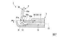
パピロトーム2は、図7および図8に示すように、内視鏡3のチャンネル51に挿入部10を挿入し、チャンネル51の先端から処置部30を突出させた向き調整状態において、後述するように処置部30の軸線C1周りの向きを調整される。この向き調整状態において、パピロトーム2の被挟持部13は、起上しきった起上台61とチャンネル51の内周面との間に挟持される。
When the
As shown in FIGS. 7 and 8, the
ここで、図6に示すように、内視鏡3のチャンネル51にパピロトーム2を挿通せずに起上台61を起上しきったときに、起上台61とチャンネル51の内周面の内接円のうち最大のものの直径、すなわち起上台61の被挟持部13を挟む部分61aとチャンネル51の内周面の被挟持部13を挟む部分51aの内接円のうち最大のものの直径L2を規定する。このとき、この直径L2よりも、前述の被挟持部13の先端側の外径L1の方が大きい。被挟持部13の基端側の外径も被挟持部13の先端側の外径よりも大きいため、内接円のうち最大のものの直径L2よりも被挟持部13の基端側の外径の方が大きいことになる。
図8に示すように、起上しきった起上台61とチャンネル51の内周面との間にパピロトーム2の被挟持部13が挟持されたときに、先端硬質部56にストッパ61sは当接しない。起上台61およびチャンネル51の内周面と被挟持部13との間には、摩擦力が作用する。
Here, as shown in FIG. 6, when the raising
As shown in FIG. 8, the
次に、以上のように構成されたパピロトーム2を使用するパピロトーム2の使用方法を、パピロトーム2を使用した手技を例にとって説明する。図9は、パピロトーム2の使用方法を示すフローチャートである。
まず、電源から照明ユニット56bに電力を供給し、照明ユニット56bの周辺を照明する。反射光による画像を観察ユニット56cで取得し、電気信号に変換する。観察ユニット56cは、変換した電気信号を配線およびユニバーサルコード75を介して表示部に送信し、この画像が表示部に表示される。術者である使用者は、表示部に表示された画像を確認しながら、必要に応じてノブ71を操作して湾曲部57を湾曲させつつ患者の自然開口である口から内視鏡3の内視鏡挿入部50を挿入する。図10に示すように、十二指腸P1を通して十二指腸乳頭P2付近まで内視鏡挿入部50を導入する。
Next, a method for using the
First, power is supplied from the power source to the
内視鏡3の鉗子栓73の貫通孔73aを通してチャンネル51に、パピロトーム2の挿入部10を挿入させる。鉗子栓73の弁と挿入部10との間に摩擦力が作用し、鉗子栓73と挿入部10とがほぼ水密に封止される。挿入部10の挿入量を調整して、図10に示すように、チャンネル51の先端から処置部30を突出させた向き調整状態にする(図9におけるステップS2)。
チャンネル51および起上台61に案内されて、処置部30は内視鏡挿入部50の先端硬質部56の側方に突出する。これにより、処置部30の先端は十二指腸乳頭P2の奥の胆管P3の方向に向けられる。
処置部30の先端を十二指腸乳頭P2に挿入する。
The
Guided by the
The distal end of the
胆管P3の位置をX線撮影により確認するときは、送液口金45に装着した不図示のシリンジから送液ルーメン18に造影剤を注入する。造影剤は、送液ルーメン18を通して胆管P3内に注入される。
When the position of the bile duct P3 is confirmed by X-ray imaging, a contrast medium is injected into the
使用者は、表示部に表示された画像で、図11に示すように、はちまき襞P4の位置を確認して切開する方向を決定するとともに、現在のナイフ部19aの向きを確認する。そして、切開すべき方向を矢印B1に示す12時方向と決定し、ナイフ部19aの向きが2時方向に向いていると確認したとする。
ここで使用者は、以下に説明するようにナイフ部19aの向きを2時方向から12時方向に変える。
As shown in FIG. 11, the user determines the direction of incision by confirming the position of the bean paste ridge P4 in the image displayed on the display unit, and confirms the current orientation of the
Here, the user changes the direction of the
まず、レバー72を操作して図12に示すように起上台61を起上させきり、挿入部10の被挟持部13を起上させきった起上台61とチャンネル51の内周面との間で挟持する(ステップS4)。このとき、起上台61の部分61aとチャンネル51の内周面の部分51aの内接円のうち最大のものの直径L2よりも被挟持部13の外径L1の方が大きいため、起上台61およびチャンネル51の内周面と被挟持部13との間に摩擦力(回転トルクに対するカウンタートルク)が作用するようになる。
使用者は、操作部40を挿入部10の軸線C1周りに回動させることで、図2に示すようにトルク伝達部材12の基端側においてトルク伝達部材12を周方向の一方側E1に回動させる。これにより、使用者が操作部40で入力した回転トルクをトルク伝達部材12が先端側に伝達してシース本体11aが軸線C1周りに回動する。
起上台61およびチャンネル51と被挟持部13との間には摩擦力が作用するため、使用者が操作部40を速く回動させても図12に示すように起上台61およびチャンネル51に対して被挟持部13がゆっくりと軸線C1周りに方向D3に回動する。このとき、シース本体11aの被挟持部13よりも基端側に回転トルクが蓄積する。
First, the
The user rotates the
Since a frictional force acts between the
使用者は、操作部40を回動させてトルク伝達部材12を介してシース本体11aに回転トルクを作用させつつ、処置部30の軸線C1周りの向きを内視鏡3の表示部に表示された画像で観察する(ステップS6)。
処置部30のナイフ部19aの向きが所望の向き、すなわち12時方向になったときに、図2に示すようにトルク伝達部材12の基端側においてトルク伝達部材12を周方向の他方側E2に回動させて、シース本体11aの被挟持部13よりも基端側に作用する回転トルクを解除する(ステップS8)。
レバー72を操作して起上台61を倒す。パピロトーム2の端子43aを、高周波電源に接続する。操作部40のリング42a、43b、43cに指を適宜入れて操作部40を把持し、スライダ43を引戻してナイフ部19aを張る。
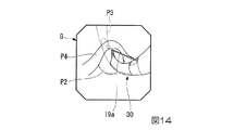
高周波電源から高周波電流を流し、レバー72を操作して起上台61を起上させたり倒したりして処置部30を首振り動作させる。ナイフ部19aが接触する十二指腸乳頭P2の組織に高周波電流とナイフ部19aの張力による圧力が加わって、図13に示すように十二指腸乳頭P2が切開される。例えば、図14に示すように、表示部の画像Gにより必要な切開量に達したことが確認できたら、高周波電流の通電を停止させる。
The user rotates the
When the direction of the
The
A high-frequency current is supplied from a high-frequency power supply, and the
患者の個人差などにより、切開すべき方向が12時方向とは異なる場合にも、前述の方法により処置部30のナイフ部19aの向きを調整することができる。
Even when the direction to be cut differs from the 12 o'clock direction due to individual differences among patients, the direction of the
十二指腸乳頭P2の切開が完了したら、スライダ43を押込んでナイフ支持部11bにナイフ部19aを沿わせてから、パピロトーム2を抜去する。
このとき、パピロトーム2の代わりに不図示のバスケット鉗子などを挿入する。バスケット鉗子は、切開された十二指腸乳頭P2から胆管P3に挿入され、結石を捕捉する。結石が大きいときは破砕し、結石が小さいときはそのまま胆管P3から排出する。結石を排出したら、バスケット鉗子および内視鏡3を体内から抜去する。
When the incision of the duodenal papilla P2 is completed, the
At this time, a basket forceps (not shown) or the like is inserted instead of the
以上説明したように、本実施形態のパピロトーム2および内視鏡システム1によれば、内視鏡3のチャンネル51に挿入部10を挿通させて、パピロトーム2をチャンネル51から処置部30を突出させた向き調整状態にする。レバー72を操作して起上台61を起上させきり、起上台61とチャンネル51の内周面との間で被挟持部13を挟持する。トルク伝達部材12を周方向の一方側E1に回動させつつ、処置部30の軸線C1周りの向きを内視鏡3で観察する。起上台61およびチャンネル51と被挟持部13との間には摩擦力が作用するため、処置部30はゆっくりと軸線C1周りに回動する。
処置部30のナイフ部19aの向きが12時方向になったときに、トルク伝達部材12の基端側においてトルク伝達部材12を周方向の他方側E2に回動させる。シース本体11aに蓄積されていた回転トルクが解除され、処置部30の向きが固定される。
このように、処置部30がゆっくりと回動するため、処置部30が使用者の予想外のタイミングで一気に回りだすのを抑え、使用者が向きを調整する時間的な猶予を増やして、処置部30を軸線C1周りの所望の向きに正確に向かせることができる。
また、このとき被挟持部13の材質がシース本体11aの材質より滑りにくい材質であれば、シース本体11aの十二指腸乳頭P2への良好な挿入性を維持しつつ、挿入部10の回転の制御のしやすさをより向上できる。
As described above, according to the
When the direction of the
In this way, since the
At this time, if the material of the sandwiched
なお、本実施形態では、前述のようにトルク伝達部材12の先端部外周を被挟持部としてもよい。この場合には、トルク伝達部材12の基端側で伝達された回転トルクを軸線C1方向において被挟持部まで効果的に伝達させることができる。
In the present embodiment, as described above, the outer periphery of the tip end portion of the
(第2実施形態)
次に、本発明の第2実施形態について図15から図26を参照しながら説明するが、前記実施形態と同一の部位には同一の符号を付してその説明は省略し、異なる点についてのみ説明する。
図15から図18に示すように、本実施形態のパピロトーム6は、挿入部90と、挿入部90よりも先端側に設けられた処置部110と、挿入部90の基端部に設けられ処置部110を操作するための操作部120とを備えている。
(Second Embodiment)
Next, a second embodiment of the present invention will be described with reference to FIGS. 15 to 26. However, the same parts as those of the above-described embodiment will be denoted by the same reference numerals and the description thereof will be omitted, and only differences will be described. explain.
As shown in FIGS. 15 to 18, the
本実施形態では、挿入部90および処置部110に、図19に示すようなマルチルーメンチューブ91が用いられている。なお、図19においては、後述するトルク伝達部材95のうち被覆チューブ101は示していない。
マルチルーメンチューブ91は、先端側の外径よりも基端側の外径の方が大きく、先端側と基端側との境となる部分に移行部91aが形成されている。マルチルーメンチューブ91には、全長にわたり前述の3つのルーメン16、17、18が形成されている。マルチルーメンチューブ91には、基端から移行部91aまでトルクルーメン(ルーメン)92が形成されている。
マルチルーメンチューブ91の先端と移行部91aとの中間部分よりも基端側がシース本体91bであり、シース本体91bよりも先端側がナイフ支持部91cである。図15および図17に示すように、シース本体91bのガイドワイヤルーメン16には、シース本体91bの外周面に達する幅狭切欠き91dが形成されている。幅狭切欠き91dは、移行部91aよりも基端側の後述する別体式シース領域R2のほぼ全長にわたり形成されている。幅狭切欠き91dの幅は、パピロトーム6と組合わせて使用するガイドワイヤW(図26参照。)の外径よりわずかに小さく形成されている。また、幅狭切欠き91dの基端には、組合わせるガイドワイヤWの外径よりも大きな幅の幅広切欠き91eが形成されている。
この幅広切欠き91eおよび幅狭切欠き91dで、切欠き91fを構成する。
In the present embodiment, a
In the
The proximal end side of the intermediate portion between the distal end of the
The
なお、マルチルーメンチューブ91は、図20に示すように、移行部91aの前後で別々に製作されたチューブ片131、132を接続して形成してもよい。この場合、3つのルーメン131aが形成された先端側のチューブ片131と、4つのルーメン132aが形成された基端側のチューブ片132とを接続することで、マルチルーメンチューブ91が構成される。
As shown in FIG. 20, the
チューブ片131、132の接続方法としては、以下に説明する方法を用いることができる。すなわち、第一の方法として、図21に示すように、チューブ片132の4つのルーメン132aに芯金F1の一端側を挿入し、4つの芯金F1のうちの3つの他端側をチューブ片131の各ルーメン131aに挿入する。チューブ片131およびチューブ片132の端面同士を突合せる。チューブ片131、132の突合せた部分の外側に熱収縮チューブF2を被せる。
図22に示すように、熱収縮チューブF2に熱Hを作用させることで熱収縮チューブF2を収縮させ、チューブ片131、132を接続する。この後で、図23に示すように、マルチルーメンチューブ91のチューブ片131、132から芯金F1を取外す。
As a method of connecting the
As shown in FIG. 22, the heat shrinkable tube F2 is contracted by applying heat H to the heat shrinkable tube F2, and the
また、図24に示すように、チューブ片132の4つのルーメン132aのうちの3つと、チューブ片131の3つのルーメン131aとに接続用のパイプF3を圧入して、チューブ片131、132を接続し、マルチルーメンチューブ91を構成する方法がある。
マルチルーメンチューブ91のこれらの製造方法では、移行部91aの先端側と基端側でチューブ片131、132を別々に製作できるため、それぞれ異なった材質でチューブ片131、132を製作できる。例えば、先端側のチューブ片131は、処置部30のナイフ部19aで切開することで熱が発生するため、耐熱性の高いフッ素樹脂(より詳しくは、PTFE)で製作し、基端側のチューブ片132は、材料が安価なポリアミド、ポリエチレン、ポリプロピレンなど製作してもよい。
Further, as shown in FIG. 24, the
In these manufacturing methods of the
挿入部90は、図15から図18に示すように、前述のシース本体91bと、シース本体91bに設けられたトルク伝達部材95と、シース本体91bの先端側に設けられた被挟持部96とを有している。
トルク伝達部材95は、図15および図19に示すように、金属製のブレード99と、先端部がブレード99の外周面に固定されたワイヤ100と、ブレード99を被覆する被覆チューブ101とを有している。
ワイヤ100は、図16および図19に示すように本実施形態では複数の素線100aを軸線C1に平行に並べ、先端と後端のみを溶接などで互いに固定して構成している。素線100aは、例えばステンレス線やニッケルチタン合金で形成することができる。
複数の素線100aのうちの何本かは先端側に延ばされ、図15に示すようにブレード99の基端部の外周面に溶接により固定されている。すなわち、ブレード99とワイヤ100とは溶接部105により固定されている。溶接部105は、ブレード99の基端部と被覆チューブ101の基端部との間に挟まれている。
As shown in FIGS. 15 to 18, the
As shown in FIGS. 15 and 19, the
As shown in FIGS. 16 and 19, the
Some of the plurality of
ワイヤ100の基端部には、ワイヤ100よりも大径の取っ手106が固定されている。
ブレード99、被覆チューブ101は、前述のブレード22、被覆チューブ23と同様にそれぞれ形成されている。
A
The
なお、前述のように構成されたマルチルーメンチューブ91に対して、ブレード99およびワイヤ100は以下のように取付けられている。すなわち、図25に示すように、シース本体91bにおける移行部91aよりも先端側の部分にブレード99を外嵌させ、接着材や熱収縮チューブなどで固定する。マルチルーメンチューブ91のトルクルーメン92に基端側から取っ手106が固定されたワイヤ100を挿通させる。トルクルーメン92から先端側に突出したワイヤ100とブレード99とを溶接部105により固定する。
The
シース本体91b、ブレード99、および被覆チューブ101は、屈曲した内視鏡のチャンネルの中でも屈曲して回転トルクが伝えやすいように柔軟性のある接着剤で固定したり、もしくはもともとの内径がブレード99の外径よりも小さい収縮チューブで被覆チューブ101を構成し、被覆チューブ101の収縮力でブレード99が屈曲しやすいように柔軟に密着させたりして構成する。
被挟持部96は、図15に示すように、シース本体91bの先端外周に固定されたアウターチューブからなる。被挟持部96の基端側はブレード99を外嵌した状態でブレード99に固定されている。被挟持部96の基端側の外径は、被覆チューブ101の外径にほぼ等しい。被挟持部96は、被覆チューブ101と同一の材料で形成することができる。被挟持部96の先端側の軸線C1に直交する平面による断面は円形であり、この断面の外径は前述のL1に等しい。被挟持部96の基端側の外径は、被挟持部96の先端側の外径よりも大きい。
被挟持部96がブレード99に固定されていることで、トルク伝達部材95から被挟持部96に回転トルクが伝わるようになっている。
The sheath
As shown in FIG. 15, the sandwiched
Since the sandwiched
なお、この例では、被挟持部96がアウターチューブからなるとしたが、トルク伝達部材95の先端部外周(被覆チューブ101の先端部外周)を被挟持部としてもよい。別の方法としては、シース本体91bの先端部を熱成型によって外径を膨らませて被挟持部としてもよい。
挿入部90の先端側は、シース本体91bの外周面の外側にブレード99および被覆チューブ101が取付けられた一体式シース領域R1である。一方で、挿入部90の基端側は、シース本体91bの外周面の外側にワイヤ100が取付けられておらず、シース本体91bのトルクルーメン92内にワイヤ100が回動操作可能に配されている別体式シース領域R2である。
マルチルーメンチューブ91の別体式シース領域R2に対応する部分は、トルク伝達部材95よりも回転トルクの伝達力が小さい、言い換えるとねじれやすい材料で形成されている。
In this example, the sandwiched
The distal end side of the
The portion corresponding to the separate sheath region R2 of the
処置部110は、第1実施形態の処置部30においてナイフ支持部11bに代えてナイフ支持部91cが用いられているだけで、処置部30と同様の構成となっている。
操作部120の操作部本体121は、第1実施形態の操作部本体41に対して、トルクルーメン92が操作部本体121の基端まで延長されるように形成されている。ガイドワイヤルーメン16に連通するガイドワイヤ口金44は設けられていない。
The
The operation unit
このように構成されたパピロトーム6は、図26に示すように前述の内視鏡3と組合わせて内視鏡システム7を構成する。
本パピロトーム6を使用した手技は、ガイドワイヤWを内視鏡3の鉗子栓73の貫通孔73aを通してチャンネル51に挿通する。挿入部90における幅狭切欠き91dが形成された部分が鉗子栓73に挿通され、幅広切欠き91eが鉗子栓73よりも基端側に位置するようにする。このガイドワイヤWを、十二指腸P1を通して胆管P3内に導入しておく。
パピロトーム6のガイドワイヤルーメン16の先端にガイドワイヤWの基端部を挿通し、ガイドワイヤWを挿入部90の幅広切欠き91eから外部に引出す。鉗子栓73の貫通孔73aを通してチャンネル51に、パピロトーム6の挿入部90を挿入させる。鉗子栓73に挿入部90が挿通されると、鉗子栓73の弁と挿入部90との間に摩擦力が作用し、鉗子栓73と挿入部90とがほぼ水密に封止される。
使用者は、内視鏡3のチャンネル51に挿入する挿入部90の挿入量を調整入して、パピロトーム6をチャンネル51から処置部110を突出させた向き調整状態にする。このとき、鉗子栓73には別体式シース領域R2の挿入部90、すなわちシース本体91bが挿通されている。摩擦力は鉗子栓73と別体式シース領域R2のシース本体91bとの間に作用している。
The
In the procedure using the
The proximal end portion of the guide wire W is inserted into the distal end of the
The user adjusts the insertion amount of the
取っ手106を軸線C1周りに回動させると、回転トルクはシース本体91bのトルクルーメン92に挿通されたワイヤ100を介してブレード99や被覆チューブ101に伝達され一体式シース領域R1に伝わる。このとき、別体式シース領域R2の先端は一体式シース領域R1の基端側と移行部91aを介して接続されているため、一体式シース領域R1から別体式シース領域R2にも回転トルクが伝わる。しかし、マルチルーメンチューブ91はトルク伝達部材95よりも回転トルクの伝達力が低くねじれやすい材料でできているため、別体式シース領域R2の先端に加わった回転トルクはマルチルーメンチューブ91がねじれることで吸収される。したがって、操作部本体121まで回転トルクは伝わらず、操作部本体121を手元で軸線C1周りに回転させる必要は生じない。
また、ワイヤ100はトルクルーメン92に挿通されているため、取っ手106から伝達される回転トルクが鉗子栓73による摩擦力の影響を受けることが抑制される。
処置部110の先端を十二指腸乳頭P2に挿入するときに、ガイドワイヤWに沿って挿入することで手技が容易となる。
チャンネル51に対してブレード99や被覆チューブ101が回動し、処置部110の向きが変わる。
When the
Further, since the
When the distal end of the
The
以上説明したように、本実施形態のパピロトーム6および内視鏡システム7によれば、挿入部90の基端側を軸線C1周りに回動させたときに、処置部110を軸線C1周りの所望の向きに正確に向かせることができる。
パピロトーム6を向き調整状態にしたときに、鉗子栓73には別体式シース領域R2のシース本体91bが挿通され、ワイヤ100はシース本体91bのトルクルーメン92に挿通されている。したがって、ワイヤ100に伝達される回転トルクが鉗子栓73による摩擦力の影響を受けることを抑制し、この回転トルクをトルク伝達部材95の先端側に効果的に伝達させることができる。
また、ワイヤ100を回転させてトルク伝達部材95に回転トルクを伝達させても、操作部120にはこの回転トルクが伝わらない。ワイヤ100の回転に対応させて操作部120を回転させる必要がないため、操作部120の回転操作が容易である。
As described above, according to the
When the
Further, even if the
ワイヤ100の外径はブレード99や被覆チューブ101の外径よりも小さいため、ブレード99などが設けられた部分に比べてワイヤ100が設けられた部分におけるトルク伝達部材95の材料コストを低減させることができる。
別体式シース領域R2におけるシース本体91bのガイドワイヤルーメン16に切欠き91fが形成されている。このため、ガイドワイヤルーメン16に挿通したガイドワイヤWを切欠き91fから外部に引出し、挿入部90をガイドワイヤWに沿って挿入する手技を容易に行うことができる。
Since the outer diameter of the
A
また、幅狭切欠き91dはガイドワイヤWの外径よりもわずかに小さい幅で作られている。マルチルーメンチューブ91は樹脂材料で形成されているため弾性変形が可能であり、マルチルーメンチューブ91を弾性的に変形させることでガイドワイヤWを幅狭切欠き91dからも外部に引き出すことができる。ガイドワイヤWがマルチルーメンチューブ91の外部に引き出されている位置を、幅狭切欠き91dにおける鉗子栓73の近傍のガイドワイヤ操作位置Q(図26参照。)に移動させることで、内視鏡3を操作する使用者がガイドワイヤWを操作(押込んだり、引戻したりなど)することが容易になる。
また、パピロトーム6だけで手技を開始し、途中でガイドワイヤWをガイドワイヤルーメンから挿入したいときも、幅狭切欠き91dはガイドワイヤWの外径より小さいため、ガイドワイヤWが幅狭切欠き91dの途中で外に出てしまうということがなく、パピロトーム6の先端までガイドワイヤWを挿入することができる。
The
In addition, when the procedure is started only with the
なお、本実施形態では、ワイヤ100は複数の素線100aを軸線C1に平行に並べて構成されているとした。しかし、ワイヤが複数の素線100aを撚って構成されているとしてもよいし、ワイヤが単線から構成されているとしてもよい。ワイヤが単線から構成されている場合には、ワイヤの先端部を平板状に削り、この削った部分をブレード99に溶接することが好ましい。
In the present embodiment, the
以上、本発明の第1実施形態および第2実施形態について図面を参照して詳述したが、具体的な構成はこの実施形態に限られるものではなく、本発明の要旨を逸脱しない範囲の構成の変更、組合わせなども含まれる。さらに、各実施形態で示した構成のそれぞれを適宜組合わせて利用できることは、言うまでもない。
例えば、前記第1実施形態および第2実施形態では、シース本体およびナイフ支持部に3つまたは4つのルーメンが形成されているとしたが、これらには少なくとも1つのルーメンが形成されていればよい。
As mentioned above, although 1st Embodiment and 2nd Embodiment of this invention were explained in full detail with reference to drawings, the concrete structure is not restricted to this embodiment, The structure of the range which does not deviate from the summary of this invention Changes, combinations, etc. are also included. Furthermore, it goes without saying that the configurations shown in the embodiments can be used in appropriate combinations.
For example, in the first embodiment and the second embodiment, three or four lumens are formed in the sheath main body and the knife support portion, but it is sufficient that at least one lumen is formed in these. .
内視鏡用処置具がパピロトームであるとしたが、内視鏡用処置具はこれに限られない。例えば、内視鏡用処置具が、シース部の先端にL字状の高周波ナイフが設けられた高周波処置具や、一対の把持片が開閉する把持鉗子であってもよい。内視鏡用処置具がこのように構成されていても、高周波ナイフや一対の把持片を、シース部の軸線周りの所望の向きに正確に向かせることができる。
また、処置部が軸線C1に対して回転対称ではない形状であるとした。しかし、処置部が回転対称形状であっても、内視鏡用処置具を使用中に処置部の周方向の一部に組織や体液が付着し、それら組織などを周方向に移動させて処置部を使用する場合などには、本発明を好適に用いることができる。
Although the endoscope treatment tool is a papillotome, the endoscope treatment tool is not limited to this. For example, the endoscope treatment tool may be a high-frequency treatment tool in which an L-shaped high-frequency knife is provided at the distal end of the sheath part, or a grasping forceps that opens and closes a pair of grasping pieces. Even if the endoscope treatment tool is configured in this way, the high-frequency knife and the pair of gripping pieces can be accurately oriented in a desired direction around the axis of the sheath portion.
In addition, the treatment portion has a shape that is not rotationally symmetric with respect to the axis C1. However, even if the treatment section has a rotationally symmetric shape, tissue or body fluid adheres to a part of the treatment section in the circumferential direction during use of the endoscope treatment tool, and treatment is performed by moving these tissues in the circumferential direction. The present invention can be suitably used when using parts.
本発明は、さらに以下の技術思想を含むものである。
(付記項1)
請求項1に記載の内視鏡用処置具を、前記シース部を挿通可能なチャンネルを有する内視鏡と組合わせて使用する内視鏡用処置具の使用方法であって、
前記内視鏡の前記チャンネルに前記シース部を挿通させるとともに、前記チャンネルから前記処置部を突出させ、
前記シース本体の前記被挟持部を、起上させきった前記起上台と前記チャンネルの内周面との間で挟持し、
前記トルク伝達部材の基端側において前記トルク伝達部材を周方向の一方側に回動させることで、前記シース本体を前記シース部の軸線周りに回動させて前記シース本体に回転トルクを作用させつつ、前記処置部の前記軸線周りの向きを前記内視鏡で観察し、
前記処置部が所望の向きになったときに、前記トルク伝達部材の基端側において前記トルク伝達部材を周方向の他方側に回動させて、前記シース本体の前記被挟持部よりも基端側に作用する回転トルクを解除する。
The present invention further includes the following technical ideas.
(Additional item 1)
A method for using an endoscope treatment tool according to
The sheath portion is inserted through the channel of the endoscope, and the treatment portion is protruded from the channel,
The sandwiched portion of the sheath body is sandwiched between the raising base that has been raised and the inner peripheral surface of the channel,
By rotating the torque transmitting member to one side in the circumferential direction on the proximal end side of the torque transmitting member, the sheath body is rotated around the axis of the sheath portion, and rotational torque is applied to the sheath body. While observing the direction of the treatment portion around the axis with the endoscope,
When the treatment portion is in a desired orientation, the torque transmission member is rotated to the other side in the circumferential direction on the proximal end side of the torque transmission member, and the proximal end of the sheath body is more proximal than the sandwiched portion. Release the rotational torque acting on the side.
1、7 内視鏡システム
2、6 パピロトーム(内視鏡用処置具)
3 内視鏡
10、90 挿入部(シース部)
11a、91b シース本体
12、95 トルク伝達部材
13、96 被挟持部
16 ガイドワイヤルーメン(ルーメン)
17 ナイフルーメン(ルーメン)
18 送液ルーメン(ルーメン)
30、110 処置部
40、120 操作部
51 チャンネル
51a、61a 部分
61 起上台
73 鉗子栓
91f 切欠き
92 トルクルーメン(ルーメン)
C1 軸線
L1 外径
L2 直径
R1 一体式シース領域
R2 別体式シース領域
1,7
3
11a,
17 Knife lumen (lumen)
18 Liquid feeding lumen (lumen)
30, 110
C1 axis L1 outer diameter L2 diameter R1 integral sheath region R2 separate sheath region
Claims (5)
可撓性を有し、長手軸に沿って延びたルーメンを有するシース本体と、
前記シース本体よりも先端側に設けられた処置部と、
前記シース本体の基端部に設けられ、前記ルーメンと連通する開口を有する操作部本体と、
前記シース本体の軸線に沿って延び、前記開口から突出する基端を有するトルク伝達部材と、
前記トルク伝達部材の前記基端に取り付けられ、前記トルク伝達部材を回動操作可能なハンドルと、
を備え、
前記トルク伝達部材は、前記シース本体の先端領域に取り付けられた領域を有し、前記領域と前記ハンドルとの間では、前記シース本体の前記ルーメン内で前記シース本体の前記長手軸に沿って延び、前記シース本体に対して回動自在に設けられており、
前記シース本体は、前記チャンネルに前記シース本体が挿入されたときに起上した前記起上台と前記チャンネルの内周面との間に挟持される被挟持部をさらに有し、
前記トルク伝達部材は、前記シース本体の基端側から前記シース本体の軸線方向において前記被挟持部まで延び、使用者が前記ハンドルで入力した回転トルクを伝達して前記シース本体を前記軸線周りに回動可能であり、
前記被挟持部の外径は、前記起上台を最大に起上したときの、前記起上台と前記チャンネルの内周面とにおける前記被挟持部を挟む部分の内接円のうち最大のものの直径よりも大きく、
前記チャンネルの基端部には、前記シース本体を挿通可能とするとともに、前記チャンネルからの液漏れを減らす鉗子栓が設けられ、
前記シース本体の先端側は、前記シース本体の外周面の外側に前記トルク伝達部材が取付けられた一体式シース領域であり、
前記シース本体の基端側は、前記シース本体の外周面の外側に前記トルク伝達部材が取付けられていない別体式シース領域であり、
前記チャンネルの先端から前記処置部を突出させた状態において、前記鉗子栓に前記別体式シース領域が挿通されている、
内視鏡用処置具。 An endoscopic treatment tool used in combination with an endoscope having a raising platform at the tip of a channel,
A sheath body having a lumen having a lumen extending along the longitudinal axis;
A treatment section provided on the distal side of the sheath body;
An operating portion main body provided at a proximal end portion of the sheath main body and having an opening communicating with the lumen;
A torque transmission member extending along the axis of the sheath body and having a proximal end protruding from the opening;
A handle attached to the base end of the torque transmission member and capable of rotating the torque transmission member;
With
The torque transmission member has a region attached to a distal end region of the sheath body, and extends along the longitudinal axis of the sheath body within the lumen of the sheath body between the region and the handle. , Provided to be rotatable with respect to the sheath body ,
The sheath body further includes a sandwiched portion that is sandwiched between the raising base that is raised when the sheath body is inserted into the channel and the inner peripheral surface of the channel,
The torque transmitting member extends from the proximal end side of the sheath body to the sandwiched portion in the axial direction of the sheath body, transmits a rotational torque input by a user with the handle, and moves the sheath body around the axis. Is pivotable,
The outer diameter of the sandwiched portion is the diameter of the largest inscribed circle of the portion sandwiching the sandwiched portion between the elevator base and the inner peripheral surface of the channel when the elevator base is raised to the maximum. Bigger than
At the proximal end of the channel, a forceps plug is provided that allows the sheath body to be inserted and reduces liquid leakage from the channel.
The distal end side of the sheath body is an integral sheath region in which the torque transmission member is attached to the outside of the outer peripheral surface of the sheath body.
The proximal end side of the sheath body is a separate sheath region where the torque transmission member is not attached to the outside of the outer peripheral surface of the sheath body,
In the state where the treatment portion is projected from the tip of the channel, the separate sheath region is inserted through the forceps plug.
Endoscopic treatment tool.
前記トルク伝達部材の前記領域は、前記移行部よりも前記シース本体の前記先端側に取り付けられ、
前記トルク伝達部材は、前記移行部よりも前記シース本体の前記基端側において、前記シース本体の前記ルーメン内で前記シース本体の前記長手軸に沿って延び、前記シース本体に対して回動自在に設けられている
請求項1に記載の内視鏡用処置具。 The sheath body is formed at a boundary portion between the distal end side and the proximal end side of the sheath body so that the outer diameter on the proximal end side is larger than the outer diameter on the distal end side of the sheath body. Have a transition,
The region of the torque transmission member is attached to the distal end side of the sheath body from the transition portion,
The torque transmission member extends along the longitudinal axis of the sheath body within the lumen of the sheath body and is rotatable with respect to the sheath body on the proximal end side of the sheath body with respect to the transition portion. The endoscope treatment tool according to claim 1, wherein the endoscope treatment tool is provided.
前記シース本体の前記ルーメン内で前記シース本体の軸線に沿って延び、前記シース本体に対して回動自在に設けられたワイヤと、
前記ワイヤの先端に取り付けられ、且つ前記シース本体の先端領域に外嵌されたブレードと、を有する
請求項1に記載の内視鏡用処置具。 The torque transmission member is
A wire that extends along the axis of the sheath body within the lumen of the sheath body and is provided so as to be rotatable with respect to the sheath body;
The endoscope treatment tool according to claim 1, further comprising: a blade attached to a distal end of the wire and externally fitted to a distal end region of the sheath body.
前記別体式シース領域における1つの前記ルーメン内に前記トルク伝達部材が配され、
前記別体式シース領域における他の1つの前記ルーメンには、前記シース本体の外周面に達する切欠きが形成されている請求項1に記載の内視鏡用処置具。 The sheath body in the separate sheath region has two or more lumens;
The torque transmitting member is disposed within one lumen in the separate sheath region;
Said further body formula Other one of the lumens in the sheath region, the endoscope treatment instrument according to claim 1, which is reached notch formed on the outer peripheral surface of the sheath body.
前記シース本体を挿通可能であって、先端部に前記起上台を有する前記チャンネルが形成された内視鏡と、
を備える内視鏡システム。 The endoscope treatment tool according to claim 1 ,
An endoscope in which the sheath body can be inserted and the channel having the raising base is formed at a distal end portion;
An endoscope system comprising:
Priority Applications (5)
| Application Number | Priority Date | Filing Date | Title |
|---|---|---|---|
| JP2013135458A JP6204085B2 (en) | 2013-06-27 | 2013-06-27 | Endoscopic treatment tool and endoscope system |
| EP14818816.2A EP3015077B1 (en) | 2013-06-27 | 2014-04-03 | Treatment instrument for endoscope, and endoscope system |
| CN201480008262.0A CN104981210B (en) | 2013-06-27 | 2014-04-03 | Treatment device for endoscope and endoscopic system |
| PCT/JP2014/059829 WO2014208172A1 (en) | 2013-06-27 | 2014-04-03 | Treatment instrument for endoscope, and endoscope system |
| US14/822,142 US10478044B2 (en) | 2013-06-27 | 2015-08-10 | Treatment instrument for endoscope and endoscope system |
Applications Claiming Priority (1)
| Application Number | Priority Date | Filing Date | Title |
|---|---|---|---|
| JP2013135458A JP6204085B2 (en) | 2013-06-27 | 2013-06-27 | Endoscopic treatment tool and endoscope system |
Related Child Applications (1)
| Application Number | Title | Priority Date | Filing Date |
|---|---|---|---|
| JP2017167838A Division JP6407376B2 (en) | 2017-08-31 | 2017-08-31 | Endoscopic treatment tool and endoscope system |
Publications (2)
| Publication Number | Publication Date |
|---|---|
| JP2015008827A JP2015008827A (en) | 2015-01-19 |
| JP6204085B2 true JP6204085B2 (en) | 2017-09-27 |
Family
ID=52141526
Family Applications (1)
| Application Number | Title | Priority Date | Filing Date |
|---|---|---|---|
| JP2013135458A Active JP6204085B2 (en) | 2013-06-27 | 2013-06-27 | Endoscopic treatment tool and endoscope system |
Country Status (5)
| Country | Link |
|---|---|
| US (1) | US10478044B2 (en) |
| EP (1) | EP3015077B1 (en) |
| JP (1) | JP6204085B2 (en) |
| CN (1) | CN104981210B (en) |
| WO (1) | WO2014208172A1 (en) |
Families Citing this family (9)
| Publication number | Priority date | Publication date | Assignee | Title |
|---|---|---|---|---|
| WO2017134752A1 (en) * | 2016-02-02 | 2017-08-10 | オリンパス株式会社 | Endoscopic instrument |
| WO2018144565A1 (en) * | 2017-02-01 | 2018-08-09 | Interscope, Inc. | Mechanisms for controlling rotation of outer cannula for use in endoscopic tool |
| JP6761378B2 (en) | 2017-06-13 | 2020-09-23 | オリンパス株式会社 | Endoscopic treatment tool |
| CN107260257B (en) * | 2017-07-20 | 2024-06-07 | 郑明友 | Three-cavity duodenal papilla incision knife |
| JP6856759B2 (en) * | 2017-09-06 | 2021-04-14 | オリンパス株式会社 | Radiofrequency treatment tool and endoscopic system |
| DE112018007936T5 (en) * | 2018-10-19 | 2021-05-20 | Olympus Corporation | Endoscope treatment tool |
| CN111265179B (en) * | 2020-02-26 | 2023-11-03 | 上海澳华内镜股份有限公司 | Auxiliary tool for advancing treatment tool and endoscope system |
| JP2022052257A (en) * | 2020-09-23 | 2022-04-04 | 富士フイルム株式会社 | Treatment instrument for endoscope, and endoscopic system |
| RU2771260C1 (en) * | 2021-05-25 | 2022-04-29 | Государственное автономное учреждение здравоохранения "Межрегиональный клинико-диагностический центр" (ГАУЗ "МКДЦ") | Method for endoscopic sphincter-preserving atypical papillotomy in choledocholithiasis |
Family Cites Families (17)
| Publication number | Priority date | Publication date | Assignee | Title |
|---|---|---|---|---|
| US4619263A (en) * | 1984-05-30 | 1986-10-28 | Advanced Cardiovascular Systems, Inc. | Adjustable rotation limiter device for steerable dilatation catheters |
| US4686963A (en) * | 1986-03-05 | 1987-08-18 | Circon Corporation | Torsion resistant vertebrated probe of simple construction |
| WO1996014020A1 (en) * | 1994-11-02 | 1996-05-17 | Olympus Optical Co. Ltd. | Endoscope operative instrument |
| JP3417778B2 (en) * | 1997-01-17 | 2003-06-16 | ペンタックス株式会社 | Endoscope treatment tool |
| US20040044350A1 (en) * | 1999-04-09 | 2004-03-04 | Evalve, Inc. | Steerable access sheath and methods of use |
| ATE308935T1 (en) | 2000-08-14 | 2005-11-15 | Boston Scient Ltd | DIRECTORABLE SPHINCTEROTOME |
| JP4896351B2 (en) | 2000-08-14 | 2012-03-14 | ボストン サイエンティフィック リミテッド | Steerable sphincter and cannulation, nipple incision, and sphincter incision |
| US6482221B1 (en) * | 2000-08-21 | 2002-11-19 | Counter Clockwise, Inc. | Manipulatable delivery catheter for occlusive devices (II) |
| US7357806B2 (en) * | 2001-12-06 | 2008-04-15 | Ethicon Endo-Surgery, Inc. | Clip ejector for endoscopic clip applier |
| JP4275004B2 (en) | 2004-05-24 | 2009-06-10 | Hoya株式会社 | High frequency cutting tool for endoscope |
| ATE462349T1 (en) * | 2005-04-15 | 2010-04-15 | Wilson Cook Medical Inc | ENDOSCOPIC DEVICE WITH LIFTER |
| JP4716787B2 (en) | 2005-05-31 | 2011-07-06 | オリンパスメディカルシステムズ株式会社 | Submucosal layer peeling treatment device and submucosal layer peeling treatment device system |
| JP4970877B2 (en) * | 2006-05-17 | 2012-07-11 | オリンパスメディカルシステムズ株式会社 | Endoscope |
| ATE455495T1 (en) * | 2006-12-04 | 2010-02-15 | Ethicon Endo Surgery Inc | HANDLE SUITABLE FOR TRANSMITTING TORQUE BETWEEN A KNOB AND A CORRESPONDING OUTPUT SHAFT CONNECTABLE WITH CABLES, TUBES, OR THE LIKE |
| US8021328B2 (en) * | 2007-03-05 | 2011-09-20 | Abbott Cardiocascular Systems Inc. | Rapid exchange infusion catheter |
| US9345539B2 (en) * | 2007-08-17 | 2016-05-24 | Olympus Corporation | Treatment device |
| JP5191340B2 (en) * | 2008-10-08 | 2013-05-08 | Hoya株式会社 | Endoscopic treatment tool |
-
2013
- 2013-06-27 JP JP2013135458A patent/JP6204085B2/en active Active
-
2014
- 2014-04-03 WO PCT/JP2014/059829 patent/WO2014208172A1/en active Application Filing
- 2014-04-03 CN CN201480008262.0A patent/CN104981210B/en active Active
- 2014-04-03 EP EP14818816.2A patent/EP3015077B1/en active Active
-
2015
- 2015-08-10 US US14/822,142 patent/US10478044B2/en active Active
Also Published As
| Publication number | Publication date |
|---|---|
| WO2014208172A1 (en) | 2014-12-31 |
| CN104981210B (en) | 2017-06-06 |
| US10478044B2 (en) | 2019-11-19 |
| EP3015077A1 (en) | 2016-05-04 |
| EP3015077B1 (en) | 2020-11-11 |
| US20150342633A1 (en) | 2015-12-03 |
| JP2015008827A (en) | 2015-01-19 |
| CN104981210A (en) | 2015-10-14 |
| EP3015077A4 (en) | 2016-12-14 |
Similar Documents
| Publication | Publication Date | Title |
|---|---|---|
| JP6204085B2 (en) | Endoscopic treatment tool and endoscope system | |
| JP3722729B2 (en) | Endoscope treatment device | |
| JP6084338B2 (en) | Endoscopic submucosal dissection device and endoscope system | |
| US9345539B2 (en) | Treatment device | |
| WO2006085620A1 (en) | Flexible tube for endoscope, and endoscope device | |
| JP2009508629A (en) | Endoscope assembly having a cap and a cover | |
| US9155554B2 (en) | Tissue resection bander and related methods of use | |
| JP6482101B2 (en) | Operation unit for bending treatment tools | |
| US20170265723A1 (en) | Assist device and endoscope system | |
| US20090247822A1 (en) | Endoscope treatment instrument | |
| JP6407376B2 (en) | Endoscopic treatment tool and endoscope system | |
| JP6284182B2 (en) | Operation unit for bending treatment tools | |
| US11426232B2 (en) | Treatment instrument and endoscopic system | |
| JP3756874B2 (en) | Endoscope | |
| US10010246B2 (en) | Steerable endoscopes | |
| JPH07265320A (en) | Treatment device in living body | |
| CN220236843U (en) | Distal end cap and endoscope accessory | |
| JPH1099264A (en) | Endoscope | |
| JP2006271491A (en) | Treating instrument insertion channel of endoscope | |
| JPH05161600A (en) | Treating device for endoscope | |
| JP2003116780A (en) | Endoscope |
Legal Events
| Date | Code | Title | Description |
|---|---|---|---|
| A711 | Notification of change in applicant |
Free format text: JAPANESE INTERMEDIATE CODE: A711 Effective date: 20150204 |
|
| A521 | Request for written amendment filed |
Free format text: JAPANESE INTERMEDIATE CODE: A821 Effective date: 20150205 |
|
| A521 | Request for written amendment filed |
Free format text: JAPANESE INTERMEDIATE CODE: A821 Effective date: 20150204 |
|
| A621 | Written request for application examination |
Free format text: JAPANESE INTERMEDIATE CODE: A621 Effective date: 20151224 |
|
| A131 | Notification of reasons for refusal |
Free format text: JAPANESE INTERMEDIATE CODE: A131 Effective date: 20160830 |
|
| A521 | Request for written amendment filed |
Free format text: JAPANESE INTERMEDIATE CODE: A523 Effective date: 20161031 |
|
| A521 | Request for written amendment filed |
Free format text: JAPANESE INTERMEDIATE CODE: A821 Effective date: 20161101 |
|
| A131 | Notification of reasons for refusal |
Free format text: JAPANESE INTERMEDIATE CODE: A131 Effective date: 20170207 |
|
| A521 | Request for written amendment filed |
Free format text: JAPANESE INTERMEDIATE CODE: A523 Effective date: 20170410 |
|
| A521 | Request for written amendment filed |
Free format text: JAPANESE INTERMEDIATE CODE: A821 Effective date: 20170411 |
|
| TRDD | Decision of grant or rejection written | ||
| A01 | Written decision to grant a patent or to grant a registration (utility model) |
Free format text: JAPANESE INTERMEDIATE CODE: A01 Effective date: 20170801 |
|
| A61 | First payment of annual fees (during grant procedure) |
Free format text: JAPANESE INTERMEDIATE CODE: A61 Effective date: 20170831 |
|
| R150 | Certificate of patent or registration of utility model |
Ref document number: 6204085 Country of ref document: JP Free format text: JAPANESE INTERMEDIATE CODE: R150 |
|
| R250 | Receipt of annual fees |
Free format text: JAPANESE INTERMEDIATE CODE: R250 |
|
| R250 | Receipt of annual fees |
Free format text: JAPANESE INTERMEDIATE CODE: R250 |
|
| R250 | Receipt of annual fees |
Free format text: JAPANESE INTERMEDIATE CODE: R250 |
|
| R250 | Receipt of annual fees |
Free format text: JAPANESE INTERMEDIATE CODE: R250 |
|
| R250 | Receipt of annual fees |
Free format text: JAPANESE INTERMEDIATE CODE: R250 |