JP6201901B2 - Air flow measurement device - Google Patents
Air flow measurement device Download PDFInfo
- Publication number
- JP6201901B2 JP6201901B2 JP2014116182A JP2014116182A JP6201901B2 JP 6201901 B2 JP6201901 B2 JP 6201901B2 JP 2014116182 A JP2014116182 A JP 2014116182A JP 2014116182 A JP2014116182 A JP 2014116182A JP 6201901 B2 JP6201901 B2 JP 6201901B2
- Authority
- JP
- Japan
- Prior art keywords
- temperature
- intake air
- resistor
- flow rate
- detection signal
- Prior art date
- Legal status (The legal status is an assumption and is not a legal conclusion. Google has not performed a legal analysis and makes no representation as to the accuracy of the status listed.)
- Active
Links
Images


Classifications
-
- G—PHYSICS
- G01—MEASURING; TESTING
- G01F—MEASURING VOLUME, VOLUME FLOW, MASS FLOW OR LIQUID LEVEL; METERING BY VOLUME
- G01F25/00—Testing or calibration of apparatus for measuring volume, volume flow or liquid level or for metering by volume
- G01F25/10—Testing or calibration of apparatus for measuring volume, volume flow or liquid level or for metering by volume of flowmeters
-
- F—MECHANICAL ENGINEERING; LIGHTING; HEATING; WEAPONS; BLASTING
- F02—COMBUSTION ENGINES; HOT-GAS OR COMBUSTION-PRODUCT ENGINE PLANTS
- F02D—CONTROLLING COMBUSTION ENGINES
- F02D41/00—Electrical control of supply of combustible mixture or its constituents
- F02D41/02—Circuit arrangements for generating control signals
- F02D41/18—Circuit arrangements for generating control signals by measuring intake air flow
-
- G—PHYSICS
- G01—MEASURING; TESTING
- G01F—MEASURING VOLUME, VOLUME FLOW, MASS FLOW OR LIQUID LEVEL; METERING BY VOLUME
- G01F1/00—Measuring the volume flow or mass flow of fluid or fluent solid material wherein the fluid passes through a meter in a continuous flow
- G01F1/68—Measuring the volume flow or mass flow of fluid or fluent solid material wherein the fluid passes through a meter in a continuous flow by using thermal effects
- G01F1/684—Structural arrangements; Mounting of elements, e.g. in relation to fluid flow
- G01F1/6842—Structural arrangements; Mounting of elements, e.g. in relation to fluid flow with means for influencing the fluid flow
-
- G—PHYSICS
- G01—MEASURING; TESTING
- G01F—MEASURING VOLUME, VOLUME FLOW, MASS FLOW OR LIQUID LEVEL; METERING BY VOLUME
- G01F1/00—Measuring the volume flow or mass flow of fluid or fluent solid material wherein the fluid passes through a meter in a continuous flow
- G01F1/68—Measuring the volume flow or mass flow of fluid or fluent solid material wherein the fluid passes through a meter in a continuous flow by using thermal effects
- G01F1/684—Structural arrangements; Mounting of elements, e.g. in relation to fluid flow
- G01F1/6845—Micromachined devices
-
- G—PHYSICS
- G01—MEASURING; TESTING
- G01F—MEASURING VOLUME, VOLUME FLOW, MASS FLOW OR LIQUID LEVEL; METERING BY VOLUME
- G01F1/00—Measuring the volume flow or mass flow of fluid or fluent solid material wherein the fluid passes through a meter in a continuous flow
- G01F1/68—Measuring the volume flow or mass flow of fluid or fluent solid material wherein the fluid passes through a meter in a continuous flow by using thermal effects
- G01F1/684—Structural arrangements; Mounting of elements, e.g. in relation to fluid flow
- G01F1/688—Structural arrangements; Mounting of elements, e.g. in relation to fluid flow using a particular type of heating, cooling or sensing element
- G01F1/69—Structural arrangements; Mounting of elements, e.g. in relation to fluid flow using a particular type of heating, cooling or sensing element of resistive type
- G01F1/692—Thin-film arrangements
-
- G—PHYSICS
- G01—MEASURING; TESTING
- G01F—MEASURING VOLUME, VOLUME FLOW, MASS FLOW OR LIQUID LEVEL; METERING BY VOLUME
- G01F1/00—Measuring the volume flow or mass flow of fluid or fluent solid material wherein the fluid passes through a meter in a continuous flow
- G01F1/68—Measuring the volume flow or mass flow of fluid or fluent solid material wherein the fluid passes through a meter in a continuous flow by using thermal effects
- G01F1/696—Circuits therefor, e.g. constant-current flow meters
- G01F1/698—Feedback or rebalancing circuits, e.g. self heated constant temperature flowmeters
- G01F1/699—Feedback or rebalancing circuits, e.g. self heated constant temperature flowmeters by control of a separate heating or cooling element
-
- G—PHYSICS
- G01—MEASURING; TESTING
- G01F—MEASURING VOLUME, VOLUME FLOW, MASS FLOW OR LIQUID LEVEL; METERING BY VOLUME
- G01F15/00—Details of, or accessories for, apparatus of groups G01F1/00 - G01F13/00 insofar as such details or appliances are not adapted to particular types of such apparatus
- G01F15/02—Compensating or correcting for variations in pressure, density or temperature
- G01F15/04—Compensating or correcting for variations in pressure, density or temperature of gases to be measured
- G01F15/043—Compensating or correcting for variations in pressure, density or temperature of gases to be measured using electrical means
- G01F15/046—Compensating or correcting for variations in pressure, density or temperature of gases to be measured using electrical means involving digital counting
-
- G—PHYSICS
- G01—MEASURING; TESTING
- G01F—MEASURING VOLUME, VOLUME FLOW, MASS FLOW OR LIQUID LEVEL; METERING BY VOLUME
- G01F5/00—Measuring a proportion of the volume flow
-
- F—MECHANICAL ENGINEERING; LIGHTING; HEATING; WEAPONS; BLASTING
- F02—COMBUSTION ENGINES; HOT-GAS OR COMBUSTION-PRODUCT ENGINE PLANTS
- F02D—CONTROLLING COMBUSTION ENGINES
- F02D2200/00—Input parameters for engine control
- F02D2200/02—Input parameters for engine control the parameters being related to the engine
- F02D2200/04—Engine intake system parameters
- F02D2200/0414—Air temperature
-
- F—MECHANICAL ENGINEERING; LIGHTING; HEATING; WEAPONS; BLASTING
- F02—COMBUSTION ENGINES; HOT-GAS OR COMBUSTION-PRODUCT ENGINE PLANTS
- F02D—CONTROLLING COMBUSTION ENGINES
- F02D41/00—Electrical control of supply of combustible mixture or its constituents
- F02D41/02—Circuit arrangements for generating control signals
- F02D41/18—Circuit arrangements for generating control signals by measuring intake air flow
- F02D41/187—Circuit arrangements for generating control signals by measuring intake air flow using a hot wire flow sensor
Landscapes
- Physics & Mathematics (AREA)
- Fluid Mechanics (AREA)
- General Physics & Mathematics (AREA)
- Engineering & Computer Science (AREA)
- Chemical & Material Sciences (AREA)
- Combustion & Propulsion (AREA)
- Mechanical Engineering (AREA)
- General Engineering & Computer Science (AREA)
- Measuring Volume Flow (AREA)
Description
本発明は、空気の流量を示す信号を発生する空気流量測定装置に関するものである。 The present invention relates to an air flow rate measuring device that generates a signal indicating an air flow rate.
従来から、例えば、内燃機関に吸入される吸入空気の流量(以下、吸気量と呼ぶことがある。)を示す信号(以下、吸気量検出信号と呼ぶことがある。)を発生する空気流量測定装置では、空気との伝熱を利用して吸気量検出信号を発生する熱式の検出方式を採用するものが周知であり、次のような筐体と吸気量センサとを備える。すなわち、筐体は、内燃機関への吸気路に突出するように配置され、吸気路を流れる吸入空気の一部を取り込んで通過させる内部流路を形成する。また、吸気量センサは、内部流路に突き出し、内部流路を通過する吸入空気との伝熱により吸気量検出信号を発生するものであり、次の高温抵抗および低温抵抗を有する。 Conventionally, for example, an air flow rate measurement that generates a signal (hereinafter also referred to as an intake air amount detection signal) indicating a flow rate of intake air (hereinafter also referred to as an intake air amount) sucked into an internal combustion engine. A device that employs a thermal detection system that generates an intake air amount detection signal using heat transfer with air is well known and includes the following casing and intake air amount sensor. That is, the casing is disposed so as to protrude into the intake passage to the internal combustion engine, and forms an internal flow path that takes in and passes a part of the intake air flowing through the intake passage. The intake air amount sensor generates an intake air amount detection signal by heat transfer with intake air that protrudes into the internal flow path and passes through the internal flow path, and has the following high temperature resistance and low temperature resistance.
すなわち、高温抵抗は、内部流路における吸気量に応じて通電制御され発熱量が増減するものである。また、低温抵抗は、例えば、高温抵抗の上流側等に配置されて高温抵抗の発熱の影響を受けずに、吸入空気の温度(以下、吸気温と呼ぶことがある。)に応じて抵抗値を可変し通電量を増減するものである。そして、高温抵抗および低温抵抗は、抵抗値が固定された固定抵抗とともにブリッジ回路を構成し、このブリッジ回路は、自身の所定部位における電位等に基づき、吸気量検出信号を発生するために制御される(例えば、特許文献1参照。)。 That is, the high temperature resistance is energized and controlled in accordance with the amount of intake air in the internal flow path, and the amount of heat generated is increased or decreased. The low temperature resistance is disposed, for example, on the upstream side of the high temperature resistance and is not affected by the heat generated by the high temperature resistance, and is a resistance value according to the temperature of the intake air (hereinafter sometimes referred to as intake air temperature). Is varied to increase or decrease the energization amount. The high-temperature resistance and the low-temperature resistance constitute a bridge circuit together with a fixed resistance whose resistance value is fixed, and this bridge circuit is controlled to generate an intake air amount detection signal based on a potential at a predetermined portion of the bridge circuit. (For example, refer to Patent Document 1).
ところで、空気流量測定装置に対しては、吸気量以外に吸気温を検出させる要求がある。そこで、特許文献1の空気流量測定装置では、ブリッジ回路への印加電圧(V1)、および、低温抵抗(22)と固定抵抗(24)との接続点電圧(V3)を検出することで、低温抵抗(22)を利用した吸気温の検出を可能としている(なお、カッコ内の符号は、特許文献1の記載に従うものである。)。しかし、特許文献1の空気流量測定装置によれば、電圧(V1、V3)を両方とも検出した上で、さらに、電圧(V1、V3)を用いた演算を行う必要があり、吸気温を検出するための回路構成や演算処理が煩雑になってしまう。
Incidentally, there is a demand for an air flow rate measuring device to detect the intake air temperature in addition to the intake air amount. Therefore, in the air flow rate measuring device of
そこで、ブリッジ回路に含まれる低温抵抗とは別に、リード線付きのサーミスタ等を吸気温センサとして筐体の外部に配置し、吸気路の吸気温を直接的に検出する構成が考えられている(例えば、特許文献2参照。)。これにより、1つの電気信号を検出することで吸気温の検出が可能になり、吸気温を検出するための回路構成や演算処理の煩雑さを解消することができる。しかし、吸気温センサを筐体の外部で安定的に保持したり、リード線とターミナルとの導通接合を安定させたりするために、様々な対策を施す必要があり、構造的に煩雑になってしまう。
Therefore, apart from the low temperature resistance included in the bridge circuit, a configuration is considered in which a thermistor with a lead wire or the like is disposed outside the housing as an intake air temperature sensor to directly detect the intake air temperature in the intake passage ( For example, see
本発明は、上記の問題点を解決するためになされたものであり、その目的は、空気流量測定装置において、吸気温の検出に係わる回路構成や演算処理の煩雑さ、および、構造的な煩雑さを低減することにある。 The present invention has been made to solve the above-described problems, and an object of the present invention is to complicate the circuit configuration and calculation processing related to the detection of the intake air temperature, and the structural complexity in the air flow rate measurement device. It is to reduce the thickness.
本願の第1発明によれば、空気流量測定装置は、内燃機関に吸入される吸入空気の流量および温度のそれぞれを示す信号である吸気量検出信号および吸気温検出信号を発生するものであり、以下の筐体、高温抵抗、第1低温抵抗および第2低温抵抗を備える。 According to the first invention of the present application, the air flow rate measuring device generates an intake air amount detection signal and an intake air temperature detection signal which are signals indicating the flow rate and temperature of intake air sucked into the internal combustion engine, The following housing, high temperature resistance, first low temperature resistance and second low temperature resistance are provided.
まず、筐体は、吸入空気が流れる吸気路に突出し、吸気路を流れる吸入空気の一部を取り込んで通過させる内部流路を形成する。また、高温抵抗は、内部流路に配置され、内部流路を流れる吸入空気の流量に応じて通電制御され、発熱量が増減する。また、第1低温抵抗は、高温抵抗の発熱量に応じて通電状態が変わるブリッジ回路を構成する素子であり、吸入空気の温度(吸気温)に応じて抵抗値を可変する。さらに、第2低温抵抗は、ブリッジ回路に組み入れられず、吸気温に応じて抵抗値を可変し通電量を増減する素子であり、所定の基板上に半導体や金属の膜として設けられる。 First, the housing projects into an intake passage through which intake air flows, and forms an internal flow path through which a portion of the intake air flowing through the intake passage is taken and passed. Further, the high temperature resistance is disposed in the internal flow path, and energization is controlled according to the flow rate of the intake air flowing through the internal flow path, so that the heat generation amount increases or decreases. The first low-temperature resistor is an element constituting a bridge circuit whose energization state changes according to the amount of heat generated by the high-temperature resistor, and varies in resistance value according to the intake air temperature (intake air temperature). Furthermore, the second low-temperature resistor is an element that is not incorporated in the bridge circuit but varies the resistance value according to the intake air temperature to increase or decrease the energization amount, and is provided as a semiconductor or metal film on a predetermined substrate.
そして、空気流量測定装置は、高温抵抗および第1低温抵抗の動作により生じる電気信号を用いて吸気量検出信号を発生するとともに、第2低温抵抗が発生する電気信号を吸気温検出信号として利用する。
また、空気流量測定装置は、次の第2補助抵抗を備え、第2低温抵抗の電気信号を、第2補助抵抗が発生する電気信号で補正する。第2補助抵抗は、空気流量測定装置における高温抵抗および処理部以外の部分からの伝熱により抵抗値を可変し通電量を増減する。
The air flow rate measuring device generates an intake air amount detection signal using an electrical signal generated by the operation of the high temperature resistance and the first low temperature resistance, and uses the electrical signal generated by the second low temperature resistance as the intake air temperature detection signal. .
The air flow rate measuring device includes the following second auxiliary resistor, and corrects the electric signal of the second low-temperature resistor with the electric signal generated by the second auxiliary resistor. The second auxiliary resistor increases or decreases the energization amount by changing the resistance value by heat transfer from a portion other than the high temperature resistance and the processing unit in the air flow rate measuring device.
これにより、第2低温抵抗が発生する1つの電気信号を検出することで吸気温の検出が可能になり、吸気温の検出に係わる回路構成や演算処理の煩雑さを低減することができる。また、第2低温抵抗を所定の基板上に半導体や金属の膜として設けることで、構造的な煩雑さを低減することができる。このため、空気流量測定装置において、吸気温の検出に係わる回路構成や演算処理の煩雑さ、および、構造的な煩雑さを低減することができる。
また、第2低温抵抗の電気信号を、第2補助抵抗が発生する電気信号で補正することにより、空気流量測定装置の雰囲気温度と吸気温との温度差が大きい温度過渡状態が生じたときに、吸気温検出信号に対する温度過渡状態の影響を除くことができる。このため、吸気温の検出精度を更に高めることができる。
例えば、上り坂走行のような高負荷運転により空気流量測定装置の雰囲気温度が上昇した後、アイドル運転に移行したような場合、空気流量測定装置の雰囲気温度が吸気温よりも高い温度過渡状態が生じる。この結果、吸気温検出信号では、現実の吸気温よりも高い数値を示す検出誤差が発生する。また、高負荷運転により空気流量測定装置の雰囲気温度が上昇した後、下り坂走行に移行したような場合、空気流量測定装置の雰囲気温度が走行風により早期に低下し、空気流量測定装置の雰囲気温度が吸気温よりも低い温度過渡状態が生じる。この結果、吸気温検出信号では、現実の吸気温よりも低い数値を示す検出誤差が発生する。
そこで、第2補助抵抗の電気信号によって第2低温抵抗の電気信号を補正することで、吸気温検出信号に対する温度過渡状態の影響を除く。これにより、吸気温の検出精度を更に高めることができる。
Accordingly, it is possible to detect the intake air temperature by detecting one electrical signal generated by the second low-temperature resistance, and it is possible to reduce the complexity of the circuit configuration and calculation processing related to the detection of the intake air temperature. Further, by providing the second low-temperature resistor as a semiconductor or metal film on a predetermined substrate, structural complexity can be reduced. For this reason, in the air flow rate measuring device, it is possible to reduce the complexity of the circuit configuration and calculation processing related to the detection of the intake air temperature, and the structural complexity.
Further, by correcting the electric signal of the second low-temperature resistor with the electric signal generated by the second auxiliary resistor, when a temperature transient state in which the temperature difference between the atmospheric temperature of the air flow measuring device and the intake air temperature is large occurs The influence of the temperature transient state on the intake air temperature detection signal can be eliminated. For this reason, the detection accuracy of the intake air temperature can be further enhanced.
For example, when the ambient temperature of the air flow rate measuring device rises due to high load operation such as uphill running and then shifts to idle operation, a temperature transient state where the ambient temperature of the air flow rate measuring device is higher than the intake air temperature may occur. Arise. As a result, in the intake air temperature detection signal, a detection error indicating a numerical value higher than the actual intake air temperature occurs. In addition, when the ambient temperature of the air flow rate measuring device rises due to high load operation and then shifts to downhill driving, the ambient temperature of the air flow rate measuring device decreases early due to the traveling wind, and the atmosphere of the air flow rate measuring device A temperature transient occurs where the temperature is lower than the intake air temperature. As a result, a detection error indicating a numerical value lower than the actual intake air temperature occurs in the intake air temperature detection signal.
Therefore, the influence of the temperature transient state on the intake air temperature detection signal is eliminated by correcting the electric signal of the second low-temperature resistor by the electric signal of the second auxiliary resistor. Thereby, the detection accuracy of the intake air temperature can be further enhanced.
本願の第2発明によれば、空気流量測定装置は、第2低温抵抗の電気信号の経時変化のパターンに応じて、第2低温抵抗の電気信号を補正する。According to the second invention of the present application, the air flow rate measuring device corrects the electric signal of the second low-temperature resistance in accordance with the temporal change pattern of the electric signal of the second low-temperature resistance.
これにより、第2低温抵抗の電気信号の経時変化のパターンを、様々な温度過渡状態ごとに記憶しおき、これらのパターンを用いて第2低温抵抗の電気信号を補正することで、吸気温検出信号を補正することができる。このため、温度過渡状態の影響を吸気温検出信号から除くことができるので、第2補助抵抗を設けなくても、温度過渡状態の影響を除く補正を行うことができる。As a result, the temporal change pattern of the electrical signal of the second low-temperature resistance is stored for each of various temperature transient states, and the electrical signal of the second low-temperature resistance is corrected using these patterns, thereby detecting the intake air temperature. The signal can be corrected. For this reason, since the influence of the temperature transient state can be removed from the intake air temperature detection signal, the correction for removing the influence of the temperature transient state can be performed without providing the second auxiliary resistor.
本願の第1、第2発明に従属する第3発明によれば、空気流量測定装置は、次の処理部および第1補助抵抗を備え、第2低温抵抗の電気信号を、第1補助抵抗が発生する電気信号で補正する。まず、処理部は、吸気量検出信号を発生するための処理を行う。また、第1補助抵抗は、処理部の発熱の影響を受けて抵抗値を可変し通電量を増減する。
これにより、吸気温検出信号に対する処理部の発熱の影響を除くことができるので、吸気温の検出精度を高めることができる。
According to a third invention subordinate to the first and second inventions of the present application, an air flow rate measuring device includes the following processing unit and a first auxiliary resistor, and an electric signal of the second low-temperature resistor is transmitted by the first auxiliary resistor. Correct with the generated electrical signal. First, the processing unit performs processing for generating an intake air amount detection signal. Further, the first auxiliary resistor varies the resistance value under the influence of heat generated by the processing unit, and increases or decreases the energization amount.
As a result, the influence of heat generated by the processing unit on the intake air temperature detection signal can be eliminated, so that the detection accuracy of the intake air temperature can be improved.
本願の第1〜第3発明に従属する第4発明によれば、空気流量測定装置は、次の第3補助抵抗を備え、第2低温抵抗の電気信号を、第3補助抵抗が発生する電気信号で補正する。第3補助抵抗は、高温抵抗によって内部流路で加熱された吸入空気からの伝熱により、抵抗値を可変し通電量を増減する。
これにより、加熱された吸入空気からの伝熱の影響を吸気温検出信号から除くことができるので、吸気温の検出精度を更に高めることができる。
According to a fourth invention subordinate to the first to third inventions of the present application, an air flow rate measuring device includes the following third auxiliary resistor, and the electric signal generated by the third auxiliary resistor is an electric signal of the second low-temperature resistor. Correct with the signal. The third auxiliary resistor varies the resistance value and increases / decreases the energization amount by heat transfer from the intake air heated in the internal flow path by the high temperature resistance.
As a result, the influence of heat transfer from the heated intake air can be removed from the intake air temperature detection signal, so that the detection accuracy of the intake air temperature can be further improved.
本願の第1〜第4発明に従属する第5発明によれば、吸気温検出信号は、吸気温検出信号以外の信号と併せた出力信号として他の機器に出力される。
これにより、吸気温検出信号、および、吸気温検出信号以外の信号(例えば、吸気量検出信号)をシリアル信号(第6発明)や周波数信号(第7発明)として1つの信号にまとめて出力することができる。このため、ターミナルの本数を低減してコネクタを小型化することができる。
According to the fifth invention subordinate to the first to fourth inventions of the present application, the intake air temperature detection signal is output to another device as an output signal combined with a signal other than the intake air temperature detection signal.
As a result, the intake air temperature detection signal and signals other than the intake air temperature detection signal (for example, the intake air amount detection signal) are collectively output as a single signal as a serial signal (sixth invention) or a frequency signal (seventh invention). be able to. For this reason, the number of terminals can be reduced and the connector can be downsized.
以下、発明を実施するための形態を、実施例を用いて説明する。なお、実施例は具体的な一例を開示するものであり、本願発明が実施例に限定されないことは言うまでもない。 Hereinafter, the form for inventing is demonstrated using an Example. In addition, an Example discloses a specific example, and it cannot be overemphasized that this invention is not limited to an Example.
〔実施例1の構成〕
実施例1の空気流量測定装置1の構成を、図1〜図6を用いて説明する。
空気流量測定装置1は、空気との伝熱を利用して空気の流量に応じた信号を発生する熱式の検出方式を採用するものである。そして、空気流量測定装置1は、例えば、内燃機関(図示せず)に吸入される吸入空気の流量(吸気量)を測定するため、内燃機関への吸気路2に突出するように配置され(図1参照。)、吸気量に応じた信号(吸気量検出信号)Qを発生する。なお、吸気量検出信号Qは、空気流量測定装置1と別体の電子制御ユニット(ECU)3に出力されて内燃機関の運転制御に利用される。
[Configuration of Example 1]
The structure of the air flow
The air flow
そして、空気流量測定装置1は、以下に説明する筐体4、高温抵抗5、第1低温抵抗6および処理部7を備える。
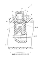
まず、筐体4は、吸気路2に突出し、吸気路2を流れる吸入空気の一部を取り込んで通過させる内部流路9を形成する。ここで、内部流路9は、主に、取り込んだ吸入空気を吸気路2における流れとほぼ同じ方向に直進させて放出する第1流路9aと、第1流路9aから吸入空気の流れの一部を分岐させるとともに周回させて放出する第2流路9bとからなる(図1および図2参照。)。なお、筐体4は、例えば、溶融樹脂の射出成形により設けられた樹脂成形品である。
The air flow
First, the
高温抵抗5は、第2流路9bに配置され、第2流路9bにおける吸気量に応じて通電制御され、発熱量が増減する。また、第1低温抵抗6は、高温抵抗5の発熱量に応じて通電状態が変わるブリッジ回路10(図6等参照:後に詳述する。)を構成する素子であり、吸入空気の温度(吸気温)に応じて抵抗値を可変する。さらに、処理部7は、吸気量検出信号Qを発生するための処理を行ったり、吸気量検出信号QをECU3に出力するための出力信号に変換したりする。
The high-
ここで、高温抵抗5、第1低温抵抗6は基板12に半導体の膜として設けられ、処理部7は主に基板13に設けられている。また、高温抵抗5、第1低温抵抗6等の基板12に設けられた素子と、基板13に設けられて処理部7を構成する素子とは、ボンディングワイヤ(図示せず。)により結線されてブリッジ回路10、14(図6等参照。)を形成する。さらに、基板12、13は、所定のターミナル15とともに樹脂により一体化されて1つのアセンブリ16を構成し、アセンブリ16は、圧入等により筐体4に装着される。そして、筐体4とアセンブリ16との一体物に対し、溶融樹脂を射出成形することで2次成形部17が設けられる。なお、コネクタ18は、2次成形部17を設けることにより形成される。
Here, the
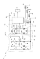
ブリッジ回路10は、高温抵抗5の発熱制御に用いられるものであり、高温抵抗5および第1低温抵抗6以外に、例えば、以下の固定抵抗20、傍熱抵抗21、比較器22およびスイッチング素子23を含んで構成されている(図3、図4および図6等参照。)。
まず、固定抵抗20は、抵抗値が温度に係わらず略一定に固定されており、第1低温抵抗6と直列に接続され、さらに、固定抵抗20と第1低温抵抗6との合成抵抗25は高温抵抗5と並列に接続されている。また、合成抵抗25では、固定抵抗20の一方側がプルアップされ、第1低温抵抗6の他方側が接地されてプルダウンされている。
The
First, the fixed
傍熱抵抗21は、高温抵抗5の近傍に設けられて高温抵抗5から熱的影響を受けて高温抵抗5と所定の温度相関にあり(図4参照。)、温度に応じて抵抗値が変化する。そして、傍熱抵抗21は、高温抵抗5および合成抵抗25と並列に接続され、傍熱抵抗21の一方側はプルアップされ、他方側は接地されてプルダウンされている。
なお、固定抵抗20および傍熱抵抗21は、基板12に半導体の膜として設けられている。
The
The fixed
スイッチング素子23は、比較器22から出力される信号の入力によりオンするものであり、自身のオン動作により電源26から高温抵抗5に給電可能となるように接続されている(図6参照。)。なお、高温抵抗5は、一方側がスイッチング素子23の出力側に接続され、他方側が接地されてプルダウンされている。
The switching
比較器22は、傍熱抵抗21の一方側の電位と、合成抵抗25における第1低温抵抗6と固定抵抗20との接続配線の電位(つまり、第1低温抵抗6の一方側、かつ、固定抵抗20の他方側の電位)とを比較し、比較結果に応じた信号をスイッチング素子23に出力する。
なお、比較器22およびスイッチング素子23は基板13に設けられて処理部7を構成する。
The
The
以上により、ブリッジ回路10は、第1低温抵抗6と傍熱抵抗21との温度差が略一定となるように通電状態が変化する。すなわち、吸気量の増加または減少により傍熱抵抗21の温度が下がったり上がったりすると、高温抵抗5の発熱量が増加したり減少したりして傍熱抵抗21と第1低温抵抗6との温度差が略一定に保たれる。
As described above, the energization state of the
ブリッジ回路14は、高温抵抗5の発熱を利用して吸気量検出信号Qを発生するものであり、以下の上流側測温抵抗28A、28B、下流側測温抵抗29A、29Bおよび比較器30を含んで構成されている(図6参照。)。
まず、上流側測温抵抗28A、28Bは、第2流路9bにおいて高温抵抗5の上流側に配置され(図4等参照。)、高温抵抗5から熱的影響を受けて温度が変わり、温度に応じて抵抗値が変化する。また、下流側測温抵抗29A、29Bは、第2流路9bにおいて高温抵抗5の下流側に配置され(図4等参照。)、高温抵抗5から熱的影響を受けて温度が変わり、温度に応じて抵抗値が変化する。
The
First, the upstream
そして、上流側測温抵抗28Aと下流側測温抵抗29Aとが直列に接続され、下流側測温抵抗29Bと上流側測温抵抗28Bとが直列に接続され、それぞれ、合成抵抗32、33を構成している(図6等参照。)。また、合成抵抗32、33は互いに並列に接続され、合成抵抗32、33の一方側(つまり、上流側測温抵抗28Aの一方側、下流側測温抵抗29Bの一方側)がプルアップされ、合成抵抗32、33の他方側(つまり、下流側測温抵抗29Aの他方側、上流側測温抵抗28Bの他方側)が接地されてプルダウンされている。
なお、上流側測温抵抗28A、28Bおよび下流側測温抵抗29A、29Bは、基板12に半導体の膜として設けられている。
The upstream
The upstream
比較器30は、合成抵抗32における上流側測温抵抗28Aと下流側測温抵抗29Aとの接続部の電位と、合成抵抗33における下流側測温抵抗29Bと上流側測温抵抗28Bとの接続部の電位を比較し、比較結果に応じた信号を出力する。
なお、比較器30は、基板13に設けられて処理部7を構成する。
The
The
以上により、ブリッジ回路14は、上流側測温抵抗28A、28Bと下流側測温抵抗29A、29Bとの温度差ΔTに応じた信号を出力する。
ここで、温度差ΔTは第2流路9bにおける吸気量に応じて変化する。つまり、高温抵抗5の上流側から下流側に至る流れ方向に関して温度分布を考えた場合、高温抵抗5の熱的影響が大きい高温範囲は、吸気量が大きいほど下流側に偏り、温度差ΔTが大きくなる。このため、ブリッジ回路14が出力する信号は吸気量に応じた信号となり、吸気量検出信号Qとして利用される。
As described above, the
Here, the temperature difference ΔT changes according to the intake air amount in the
そして、吸気量検出信号Qは、ブリッジ回路14からデジタル回路34に出力され、デジタル回路34のA/D変換部35(図7参照。)にてA/D変換され、デジタル信号としてECU3に出力される。なお、デジタル回路34は、基板13に設けられて処理部7を構成する。
ここで、基板12における各種抵抗素子の配置について、図3〜図5を用いて説明する。なお、基板12は、半導体を素材とする矩形の板状体である(以下の説明では、基板12の長手方向をX軸方向とし、短手方向をY軸方向とする。また、図3〜図5において見える面を表面とし、反対側の面を裏面とする。)。
The intake air amount detection signal Q is output from the
Here, the arrangement of various resistance elements on the
まず、基板12には略正方形の薄膜範囲37が設けられている。薄膜範囲37は、X軸方向に関して中央よりも一方側に設けられ、薄膜範囲37の表面は基板12の表面と同一平面をなし、薄膜範囲37の裏面は基板12の裏面から窪んでいる。そして、薄膜範囲37の表面に、高温抵抗5、傍熱抵抗21、上流側測温抵抗28A、28Bおよび下流側測温抵抗29A、29Bが設けられ、薄膜範囲37以外の表面に、第1低温抵抗6および固定抵抗20が設けられている。
First, the
また、基板12の表面のX軸方向の他端近傍に、ボンディングワイヤが接合される電極パッドP1〜P12が設けられ、薄膜範囲37以外の表面は、大部分がブリッジ回路10、14を構成する配線で占められている。
なお、ブリッジ回路10、14において電極パッドP1〜P12が電位的に占める位置は図6に示すとおりである。
In addition, electrode pads P1 to P12 to which bonding wires are bonded are provided in the vicinity of the other end in the X-axis direction of the surface of the
Note that the positions of the electrode pads P1 to P12 in terms of potential in the
薄膜範囲37の表面において、高温抵抗5は、例えば、自身の長手方向がX軸方向と一致するように、かつ、Y軸方向に直行するように設けられ、傍熱抵抗21は、例えば、高温抵抗5の周囲を囲うように設けられている。また、上流側測温抵抗28A、28Bは、Y軸方向に関して高温抵抗5および傍熱抵抗21の他方側に設けられ、下流側測温抵抗29A、29Bは、Y軸方向に関して高温抵抗5および傍熱抵抗21の一方側に設けられている。
On the surface of the
さらに、上流側測温抵抗28Aは、上流側測温抵抗28Bの周囲を囲うように設けられ、下流側測温抵抗29Aは、下流側測温抵抗29Bの周囲を囲うように設けられている。
また、第1低温抵抗6および固定抵抗20は、薄膜範囲37以外の表面においてY軸方向に関して中央よりも一方側に設けられている。
Furthermore, the upstream
The first low-
そして、アセンブリ16は、薄膜範囲37上の抵抗素子および第1低温抵抗6が第2流路9bに突き出るように、かつ、基板12のY軸方向一方側、他方側がそれぞれ第2流路9bにおける流れ方向の下流側、上流側となるように筐体4に装着される。なお、アセンブリ16において基板12のX軸方向他方側に基板13が位置している。
これにより、薄膜範囲37上の抵抗素子(高温抵抗5、傍熱抵抗21、上流側測温抵抗28A、28Bおよび下流側測温抵抗29A、29B)は、基板12から熱的に絶縁される。また、第1低温抵抗6は、高温抵抗5から熱的影響を受けず、高温抵抗5により加熱されていない吸入空気の流れに熱的影響を受ける。
The
Thereby, the resistance elements (the
そして、空気流量測定装置1は、特徴的な構成として、以下に説明する第2低温抵抗39、第1補助抵抗40、第2補助抵抗41および第3補助抵抗42を備え(図1、図2および図5〜図7参照。)、吸気温に応じた信号(吸気温検出信号)Tを発生する。
The air flow
第2低温抵抗39は、ブリッジ回路10、14に組み入れられず(図6参照。)、吸気温に応じて抵抗値を可変し通電量を増減する素子であり、基板12上に半導体の膜として設けられている(図3および図5参照。)。すなわち、第2低温抵抗39は、基板12の薄膜範囲37以外の表面において第1低温抵抗6および固定抵抗20の近傍に設けられ、第2流路9bに突き出ている。そして、第2低温抵抗39は、第1低温抵抗6と同様に、高温抵抗5から熱的影響を受けず、高温抵抗5により加熱されていない吸入空気の流れに熱的影響を受ける。
The second low-
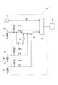
また、第2低温抵抗39は、デジタル回路34に結線され、デジタル回路34に設けられた固定抵抗39aとともに合成抵抗44を構成し(図7参照。)、合成抵抗44において、固定抵抗39aの側がプルアップされ、第2低温抵抗39の側が接地されてプルダウンされている。そして、固定抵抗39aと第2低温抵抗39との接続部の電位を、第2低温抵抗39が発生する電気信号T0として出力する。
以上により、第2低温抵抗39の電気信号T0は、後記するように、デジタル回路34において、吸気温検出信号Tの補正前の信号として利用される。
The second low-
As described above, the electric signal T0 of the second low-
第1補助抵抗40は、基板13に設けられており、処理部7の発熱の影響を受けて抵抗値を可変し通電量を増減する。また、第1補助抵抗40はデジタル回路34に結線され、デジタル回路34に設けられた固定抵抗40aとともに合成抵抗45を構成し(図7参照。)、合成抵抗45において、固定抵抗40aの側がプルアップされ、第1補助抵抗40の側が接地されてプルダウンされている。そして、固定抵抗40aと第1補助抵抗40との接続部の電位を、第1補助抵抗40が発生する電気信号T1として出力する。
The first
第2補助抵抗41は、空気流量測定装置1における高温抵抗5および処理部7以外の部分からの伝熱により抵抗値を可変し通電量を増減する。すなわち、第2補助抵抗41は、アセンブリ16において基板12、13から熱的影響を受けず、かつ、筐体4や2次成形部17から熱的影響を受ける位置に組み付けられている(図1および図2参照。)。
The second
また、第2補助抵抗41は、デジタル回路34に結線され、デジタル回路34に設けられた固定抵抗41aとともに合成抵抗46を構成し(図7参照。)、合成抵抗46において、固定抵抗41aの側がプルアップされ、第2補助抵抗41の側が接地されてプルダウンされている。そして、固定抵抗41aと第2補助抵抗41との接続部の電位を、第2補助抵抗41が発生する電気信号T2として出力する。
The second
第3補助抵抗42は、高温抵抗5によって内部流路9で加熱された吸入空気からの伝熱により、抵抗値を可変し通電量を増減する。すなわち、第3補助抵抗42は、アセンブリ16において基板12の下流側の第2流路9bに近い位置に組み付けられ(図1および図2参照。)、高温抵抗5により加熱された吸入空気から熱的影響を受ける。
The third
また、第3補助抵抗42は、デジタル回路34に結線され、デジタル回路34に設けられた固定抵抗42aとともに合成抵抗47を構成し(図7参照。)、合成抵抗47において、固定抵抗42aの側がプルアップされ、第3補助抵抗42の側が接地されてプルダウンされている。そして、固定抵抗42aと第3補助抵抗42との接続部の電位を、第3補助抵抗42が発生する電気信号T3として出力する。
The third
さらに、実施例1の空気流量測定装置1によれば、デジタル回路34は、第1〜第3補助抵抗40〜42の電気信号により吸気温検出信号T(電気信号T0)を補正する補正部49を有する。
補正部49は、例えば、下記の数式1に従って吸気温検出信号Tを補正する。
〔数式1〕T=T0+a・T1+b・T2+c・T3+d
Furthermore, according to the air flow
For example, the
[Formula 1] T = T0 + a · T1 + b · T2 + c · T3 + d
そして、補正後の吸気温検出信号Tは、A/D変換部35にてA/D変換され、デジタル信号としてECU3に出力される。このとき、デジタル化された吸気温検出信号Tおよび吸気量検出信号Qは、シリアル信号として、逐次、ECU3に出力される。
The corrected intake air temperature detection signal T is A / D converted by the A /
〔実施例1の効果〕
実施例1の空気流量測定装置1は、高温抵抗5および第1低温抵抗6の動作により生じる電気信号を用いて吸気量検出信号Qを発生するとともに、第2低温抵抗39が発生する電気信号T0を補正前の吸気温検出信号Tとして利用する。ここで、第2低温抵抗39は、高温抵抗5から受ける熱的影響が小さくなるように、基板12の薄膜範囲37以外の部分に半導体の膜として設けられ、ブリッジ回路10、14に組み入れられず、吸気温に応じて抵抗値を可変し通電量を増減する。
[Effect of Example 1]
The air flow
これにより、電気信号T0を検出することで吸気温の検出が可能になり、吸気温の検出に係わる回路構成や演算処理の煩雑さを低減することができる。また、第2低温抵抗39を、基板12に半導体の膜として設けることで、構造的な煩雑さを低減することができる。このため、空気流量測定装置1において、吸気温の検出に係わる回路構成や演算処理の煩雑さ、および、構造的な煩雑さを低減することができる。
As a result, it is possible to detect the intake air temperature by detecting the electric signal T0, and it is possible to reduce the complexity of the circuit configuration and calculation processing related to the detection of the intake air temperature. In addition, providing the second low-
また、第1補助抵抗40は、処理部7の発熱の影響を受けて抵抗値を可変し通電量を増減する。そして、第1補助抵抗40が発生する電気信号T1によって電気信号T0を補正する。
これにより、吸気温検出信号Tに対する処理部7の発熱の影響を除くことができるので、吸気温の検出精度を高めることができる。
In addition, the first
Thereby, since the influence of the heat generation of the
また、第2補助抵抗41は、空気流量測定装置1における高温抵抗5および処理部7以外の部分(主に、筐体4や2次成形部17)からの伝熱により抵抗値を可変し通電量を増減する。そして、第2補助抵抗41が発生する電気信号T2によって電気信号T0を補正する。
In addition, the second
これにより、空気流量測定装置1の雰囲気温度と吸気温との温度差が大きい温度過渡状態が生じたときに、吸気温検出信号Tに対する温度過渡状態の影響を除くことができる。このため、吸気温の検出精度を更に高めることができる。
Thereby, when the temperature transient state with a large temperature difference between the ambient temperature of the air
例えば、上り坂走行のような高負荷運転により空気流量測定装置1の雰囲気温度(つまり、筐体4や2次成形部17の温度)が上昇した後、アイドル運転に移行したような場合、空気流量測定装置1の雰囲気温度が吸気温よりも高い温度過渡状態が生じる。この結果、吸気温検出信号Tでは、現実の吸気温よりも高い数値を示す検出誤差が発生する。また、高負荷運転により空気流量測定装置1の雰囲気温度が上昇した後、下り坂走行に移行したような場合、空気流量測定装置1の雰囲気温度が走行風により早期に低下し、空気流量測定装置1の雰囲気温度が吸気温よりも低い温度過渡状態が生じる。この結果、吸気温検出信号Tでは、現実の吸気温よりも低い数値を示す検出誤差が発生する。
For example, when the atmosphere temperature of the air flow rate measuring device 1 (that is, the temperature of the
そこで、電気信号T2によって電気信号T0を補正することで、吸気温検出信号Tに対する温度過渡状態の影響を除くことができる。このため、吸気温の検出精度を更に高めることができる。 Therefore, the influence of the temperature transient state on the intake air temperature detection signal T can be eliminated by correcting the electric signal T0 with the electric signal T2. For this reason, the detection accuracy of the intake air temperature can be further enhanced.
また、第3補助抵抗42は、高温抵抗5により第2流路9bで加熱された吸入空気からの伝熱により、抵抗値を可変し通電量を増減する。そして、第3補助抵抗42が発生する電気信号T3によって電気信号T0を補正する。
これにより、加熱された吸入空気からの伝熱の影響を吸気温検出信号Tから除くことができるので、吸気温の検出精度を更に高めることができる。
The third
As a result, the influence of heat transfer from the heated intake air can be removed from the intake air temperature detection signal T, so that the detection accuracy of the intake air temperature can be further improved.
さらに、吸気温検出信号Tは、吸気量検出信号Q等の他の信号とともに、シリアル信号として、逐次、ECU3に出力される。
これにより、ターミナル15の本数を低減してコネクタ18を小型化することができる。
Further, the intake air temperature detection signal T is sequentially output to the
Thereby, the number of the
〔実施例2〕
実施例2の空気流量測定装置1は、図8に示すように、第2補助抵抗41を備えず、次の補正項演算部51を備える。
すなわち、補正項演算部51は、デジタル回路34に設けられた機能であり、第2低温抵抗39の電気信号T0の経時変化のパターンに応じて補正項Fを算出する。そして、補正部49は、第1、第3補助抵抗42の電気信号T1、T3、および、補正項Fにより、例えば、下記の数式2に従って電気信号T0を補正する。
〔数式2〕T=T0+a・T1+F+c・T3+d
[Example 2]
As shown in FIG. 8, the air flow
That is, the correction
[Formula 2] T = T0 + a · T1 + F + c · T3 + d
ここで、電気信号T0の経時変化のパターンは、内燃機関の運転状態の経時変化のパターンに応じて、種々、記憶されており、電気信号T0の経時変化のパターンごとに補正項Fの算出方法が記憶されている。 Here, the pattern of change over time of the electric signal T0 is stored in various ways according to the pattern of change over time of the operating state of the internal combustion engine, and the correction term F is calculated for each pattern of change over time of the electric signal T0. Is remembered.
例えば、上記の上り坂走行からアイドル運転への移行に対応するパターンが認められた場合、補正部49で電気信号T0を低減することができるように、補正項演算部51は、補正項Fを負の数値として求める。また、上記の上り坂走行から下り坂走行への移行に対応するパターンが認められた場合、補正部49で電気信号T0を増加することができるように、補正項演算部51は、補正項Fを正の数値として求める。
For example, when a pattern corresponding to the transition from the uphill running to the idle running is recognized, the correction
以上により、電気信号T0の経時変化のパターンに応じて吸気温検出信号Tを補正することができる。このため、温度過渡状態の影響を吸気温検出信号Tから除くことができるので、第2補助抵抗41を設けなくても、温度過渡状態の影響を除く補正を行うことができる。
As described above, the intake air temperature detection signal T can be corrected according to the temporal change pattern of the electric signal T0. For this reason, since the influence of the temperature transient state can be removed from the intake air temperature detection signal T, the correction for removing the influence of the temperature transient state can be performed without providing the second
〔変形例〕
実施例1の空気流量測定装置1によれば、補正前の吸気温検出信号T(電気信号T0)は、電気信号T1〜T3により補正され、さらに、実施例2の空気流量測定装置1によれば、電気信号T0は、電気信号T1、T3および補正項Fにより補正されていたが、補正の態様は、必要に応じて種々変更することができる。
また、実施例の空気流量測定装置1によれば、第2低温抵抗39は半導体の膜として設けられていたが、金属の膜として設けてもよい。
[Modification]
According to the air flow
Also, according to the air
また、実施例の空気流量測定装置1によれば、吸気温検出信号Tは吸気量検出信号Qとともにシリアル信号として、逐次、ECU3に出力されたが、吸気温検出信号TのECU3への出力態様は、このような態様に限定されない。例えば、空気流量測定装置1に吸入空気の湿度を検出する機能を設けておき、湿度を示す信号とともに吸気温検出信号Tを出力してもよい。また、シリアル信号に代えて、周波数信号により吸気温検出信号TをECU3に出力してもよい。例えば、吸気温検出信号Tを周波数信号の周期およびデューティ比のいずれか一方に変換するとともに吸気温検出信号T以外の信号(吸気量検出信号Qや湿度を示す信号)を他方に変換してECU3に出力してもよい。
Further, according to the air flow
1 空気流量測定装置 2 吸気路 4 筐体 5高温抵抗 6 第1低温抵抗 9 内部流路 10 ブリッジ回路 12 基板 39 第2低温抵抗 Q 吸気量検出信号 T 吸気温検出信号 T0 電気信号
DESCRIPTION OF
Claims (7)
吸入空気が流れる吸気路(2)に突出し、前記吸気路(2)を流れる吸入空気の一部を取り込んで通過させる内部流路(9)を形成する筐体(4)と、
前記内部流路(9)に配置され、前記内部流路(9)を流れる吸入空気の流量に応じて通電制御され、発熱量が増減する高温抵抗(5)と、
この高温抵抗(5)の発熱量に応じて通電状態が変わるブリッジ回路(10)を構成する素子であり、吸入空気の温度に応じて抵抗値を可変する第1低温抵抗(6)と、
前記ブリッジ回路(10)に組み入れられず、吸入空気の温度に応じて抵抗値を可変し通電量を増減する素子であり、所定の基板(12)上に半導体や金属の膜として設けられる第2低温抵抗(39)とを備え、
前記高温抵抗(5)および前記第1低温抵抗(6)の動作により生じる電気信号を用いて前記吸気量検出信号(Q)を発生するとともに、前記第2低温抵抗(39)が発生する電気信号(T0)を前記吸気温検出信号(T)として利用し、
さらに、前記空気流量測定装置(1)は、
前記吸気量検出信号(Q)を発生するための処理を行う処理部(7)と、
前記空気流量測定装置(1)における前記高温抵抗(5)および前記処理部(7)以外の部分(4、17)からの伝熱により抵抗値を可変し通電量を増減する第2補助抵抗(41)とを備え、
前記第2低温抵抗(39)の電気信号(T0)を、前記第2補助抵抗(41)が発生する電気信号(T2)で補正することを特徴とする空気流量測定装置(1)。 In an air flow rate measuring device (1) for generating an intake air amount detection signal (Q) and an intake air temperature detection signal (T) which are signals indicating the flow rate and temperature of intake air sucked into an internal combustion engine,
A housing (4) that protrudes into the intake passage (2) through which the intake air flows and forms an internal flow path (9) through which a portion of the intake air flowing through the intake passage (2) is taken and passed;
A high-temperature resistor (5) that is disposed in the internal flow path (9), is energized and controlled according to the flow rate of intake air flowing through the internal flow path (9), and the amount of heat generation increases and decreases;
A first low-temperature resistor (6) that is a device constituting a bridge circuit (10) whose energization state changes according to the amount of heat generated by the high-temperature resistor (5), and whose resistance value is variable according to the temperature of the intake air;
A second element provided as a semiconductor or metal film on a predetermined substrate (12), which is not incorporated in the bridge circuit (10) and varies the resistance value according to the temperature of the intake air to increase or decrease the energization amount. Low temperature resistance (39),
The electric signal generated by the operation of the high temperature resistor (5) and the first low temperature resistor (6) is used to generate the intake air amount detection signal (Q) and the electric signal generated by the second low temperature resistor (39). (T0) is used as the intake air temperature detection signal (T) ,
Furthermore, the air flow rate measuring device (1) includes:
A processing section (7) for performing processing for generating the intake air amount detection signal (Q);
A second auxiliary resistor that varies the resistance value by increasing and decreasing the energization amount by heat transfer from portions (4, 17) other than the high temperature resistor (5) and the processing unit (7) in the air flow rate measuring device (1). 41)
The air flow rate measuring device (1) , wherein the electric signal (T0) of the second low-temperature resistor (39) is corrected by an electric signal (T2) generated by the second auxiliary resistor (41 ).
吸入空気が流れる吸気路(2)に突出し、前記吸気路(2)を流れる吸入空気の一部を取り込んで通過させる内部流路(9)を形成する筐体(4)と、
前記内部流路(9)に配置され、前記内部流路(9)を流れる吸入空気の流量に応じて通電制御され、発熱量が増減する高温抵抗(5)と、
この高温抵抗(5)の発熱量に応じて通電状態が変わるブリッジ回路(10)を構成する素子であり、吸入空気の温度に応じて抵抗値を可変する第1低温抵抗(6)と、
前記ブリッジ回路(10)に組み入れられず、吸入空気の温度に応じて抵抗値を可変し通電量を増減する素子であり、所定の基板(12)上に半導体や金属の膜として設けられる第2低温抵抗(39)とを備え、
前記高温抵抗(5)および前記第1低温抵抗(6)の動作により生じる電気信号を用いて前記吸気量検出信号(Q)を発生するとともに、前記第2低温抵抗(39)が発生する電気信号(T0)を前記吸気温検出信号(T)として利用し、
さらに、前記第2低温抵抗(39)の電気信号(T0)の経時変化のパターンに応じて、前記第2低温抵抗(39)の電気信号(T0)を補正することを特徴とする空気流量測定装置(1)。 In an air flow rate measuring device (1) for generating an intake air amount detection signal (Q) and an intake air temperature detection signal (T) which are signals indicating the flow rate and temperature of intake air sucked into an internal combustion engine,
A housing (4) that protrudes into the intake passage (2) through which the intake air flows and forms an internal flow path (9) through which a portion of the intake air flowing through the intake passage (2) is taken and passed;
A high-temperature resistor (5) that is disposed in the internal flow path (9), is energized and controlled according to the flow rate of intake air flowing through the internal flow path (9), and the amount of heat generation increases and decreases;
A first low-temperature resistor (6) that is a device constituting a bridge circuit (10) whose energization state changes according to the amount of heat generated by the high-temperature resistor (5), and whose resistance value is variable according to the temperature of the intake air;
A second element provided as a semiconductor or metal film on a predetermined substrate (12), which is not incorporated in the bridge circuit (10) and varies the resistance value according to the temperature of the intake air to increase or decrease the energization amount. Low temperature resistance (39),
The electric signal generated by the operation of the high temperature resistor (5) and the first low temperature resistor (6) is used to generate the intake air amount detection signal (Q) and the electric signal generated by the second low temperature resistor (39). (T0) is used as the intake air temperature detection signal (T),
Further, the air flow rate measurement is characterized in that the electric signal (T0) of the second low-temperature resistance (39) is corrected in accordance with the pattern of change with time of the electric signal (T0) of the second low-temperature resistance (39). Device (1).
前記吸気量検出信号(Q)を発生するための処理を行う処理部(7)と、
前記処理部(7)の発熱の影響を受けて抵抗値を可変し通電量を増減する第1補助抵抗(40)とを備え、
前記第2低温抵抗(39)の電気信号(T0)を、前記第1補助抵抗(40)が発生する電気信号(T1)で補正することを特徴とする空気流量測定装置(1)。 In the air flow rate measuring device (1) according to claim 1 or 2,
A processing section (7) for performing processing for generating the intake air amount detection signal (Q);
A first auxiliary resistor (40) that varies the resistance value under the influence of heat generated by the processing unit (7) and increases or decreases the energization amount;
The air flow rate measuring device (1) , wherein the electric signal (T0) of the second low-temperature resistor (39) is corrected by an electric signal (T1) generated by the first auxiliary resistor (40 ).
前記高温抵抗(5)によって前記内部流路(9)で加熱された吸入空気からの伝熱により、抵抗値を可変し通電量を増減する第3補助抵抗(42)を備え、
前記第2低温抵抗(39)の電気信号(T0)を、前記第3補助抵抗(42)が発生する電気信号(T3)で補正することを特徴とする空気流量測定装置(1)。 In the air flow measuring device (1) according to any one of claims 1 to 3,
A third auxiliary resistor (42) that varies the resistance value and increases / decreases the energization amount by heat transfer from the intake air heated in the internal flow path (9) by the high temperature resistance (5);
The air flow rate measuring device (1), wherein the electric signal (T0) of the second low-temperature resistor (39) is corrected by an electric signal (T3) generated by the third auxiliary resistor (42).
前記吸気温検出信号(T)は、前記吸気温検出信号(T)以外の信号と併せた出力信号として他の機器(3)に出力されることを特徴とする空気流量測定装置(1)。 In the air flow measuring device (1) according to any one of claims 1 to 4,
The air flow rate measuring device (1) , wherein the intake air temperature detection signal (T) is output to another device (3) as an output signal combined with a signal other than the intake air temperature detection signal (T ).
前記出力信号は、前記吸気温検出信号(T)、および、前記吸気温検出信号(T)以外の信号を、シリアル信号として、逐次、送信することにより、前記他の機器(3)に出力されることを特徴とする空気流量測定装置(1)。 In the air flow measuring device (1) according to claim 5 ,
The output signal is output to the other device (3) by sequentially transmitting, as serial signals, signals other than the intake air temperature detection signal (T) and the intake air temperature detection signal (T). air flow rate measuring apparatus characterized by that (1).
前記出力信号は、前記吸気温検出信号(T)を周期およびデューティ比のいずれか一方に変換するとともに前記吸気温検出信号(T)以外の信号を他方に変換した周波数信号として、前記他の機器(3)に出力されることを特徴とする空気流量測定装置(1)。 In the air flow measuring device (1) according to claim 5 ,
The output signal is a frequency signal obtained by converting the intake air temperature detection signal (T) into either one of a cycle or a duty ratio, and converting a signal other than the intake air temperature detection signal (T) into the other. The air flow rate measuring device (1), characterized in that it is output to (3 ) .
Priority Applications (2)
| Application Number | Priority Date | Filing Date | Title |
|---|---|---|---|
| JP2014116182A JP6201901B2 (en) | 2014-06-04 | 2014-06-04 | Air flow measurement device |
| US14/728,469 US9719836B2 (en) | 2014-06-04 | 2015-06-02 | Air flow measuring device |
Applications Claiming Priority (1)
| Application Number | Priority Date | Filing Date | Title |
|---|---|---|---|
| JP2014116182A JP6201901B2 (en) | 2014-06-04 | 2014-06-04 | Air flow measurement device |
Publications (2)
| Publication Number | Publication Date |
|---|---|
| JP2015230232A JP2015230232A (en) | 2015-12-21 |
| JP6201901B2 true JP6201901B2 (en) | 2017-09-27 |
Family
ID=54769342
Family Applications (1)
| Application Number | Title | Priority Date | Filing Date |
|---|---|---|---|
| JP2014116182A Active JP6201901B2 (en) | 2014-06-04 | 2014-06-04 | Air flow measurement device |
Country Status (2)
| Country | Link |
|---|---|
| US (1) | US9719836B2 (en) |
| JP (1) | JP6201901B2 (en) |
Families Citing this family (3)
| Publication number | Priority date | Publication date | Assignee | Title |
|---|---|---|---|---|
| JP6142840B2 (en) * | 2014-04-28 | 2017-06-07 | 株式会社デンソー | Air flow measurement device |
| JP6177384B1 (en) * | 2016-05-26 | 2017-08-09 | 三菱電機株式会社 | Thermal air flow meter |
| CN113295244B (en) * | 2021-05-07 | 2021-12-17 | 安徽万瑞冷电科技有限公司 | Cryogenic fluid flow measurement and calibration method |
Family Cites Families (17)
| Publication number | Priority date | Publication date | Assignee | Title |
|---|---|---|---|---|
| US4884215A (en) * | 1987-02-27 | 1989-11-28 | Jabil Circuit Company | Airflow sensor and control circuit |
| JP3105609B2 (en) * | 1991-12-10 | 2000-11-06 | 株式会社日立製作所 | Heating resistor type air flow meter |
| JPH06109506A (en) * | 1992-09-24 | 1994-04-19 | Hitachi Ltd | Heating element type air flowmeter |
| JP3366818B2 (en) * | 1997-01-16 | 2003-01-14 | 株式会社日立製作所 | Thermal air flow meter |
| JPH11258021A (en) * | 1998-03-16 | 1999-09-24 | Hitachi Ltd | Thermal type air flow sensor |
| JP2003240620A (en) * | 2002-02-20 | 2003-08-27 | Hitachi Ltd | Gas flow measuring device |
| JP3817497B2 (en) * | 2002-06-10 | 2006-09-06 | 株式会社日立製作所 | Thermal flow meter |
| JP4177183B2 (en) * | 2003-06-18 | 2008-11-05 | 株式会社日立製作所 | Thermal air flow meter |
| JP2006058078A (en) * | 2004-08-18 | 2006-03-02 | Hitachi Ltd | Thermal air flowmeter |
| JP5210491B2 (en) * | 2006-02-03 | 2013-06-12 | 日立オートモティブシステムズ株式会社 | Thermal flow sensor |
| JP4836864B2 (en) * | 2007-05-16 | 2011-12-14 | 日立オートモティブシステムズ株式会社 | Thermal flow meter |
| JP4839395B2 (en) * | 2009-07-30 | 2011-12-21 | 日立オートモティブシステムズ株式会社 | Thermal flow meter |
| JP5406674B2 (en) * | 2009-11-06 | 2014-02-05 | 日立オートモティブシステムズ株式会社 | Thermal fluid flow sensor and manufacturing method thereof |
| JP5348196B2 (en) * | 2011-07-27 | 2013-11-20 | 株式会社デンソー | Air flow measurement device |
| JP5477358B2 (en) * | 2011-10-31 | 2014-04-23 | 株式会社デンソー | Air flow measurement device |
| JP5981319B2 (en) * | 2012-11-22 | 2016-08-31 | 日立オートモティブシステムズ株式会社 | Intake air temperature sensor device and flow rate measuring device |
| JP5558599B1 (en) * | 2013-02-13 | 2014-07-23 | 三菱電機株式会社 | Thermal air flow meter |
-
2014
- 2014-06-04 JP JP2014116182A patent/JP6201901B2/en active Active
-
2015
- 2015-06-02 US US14/728,469 patent/US9719836B2/en active Active
Also Published As
| Publication number | Publication date |
|---|---|
| US9719836B2 (en) | 2017-08-01 |
| JP2015230232A (en) | 2015-12-21 |
| US20150355005A1 (en) | 2015-12-10 |
Similar Documents
| Publication | Publication Date | Title |
|---|---|---|
| US8596113B2 (en) | Intake air temperature sensor and thermal airflow meter including the same | |
| US9599496B2 (en) | Flow rate measuring device with first temperature sensor in a main passage and second temperature sensor in a sub-passage | |
| JP5304766B2 (en) | Flow measuring device | |
| WO2004113848A1 (en) | Thermal air meter | |
| JP6201901B2 (en) | Air flow measurement device | |
| JP2016170135A (en) | Physical quantity measurement device built into flow rate measurement device, and method of measuring physical quantity | |
| JP5884769B2 (en) | Air flow measurement device | |
| US20160025539A1 (en) | Thermal Type Air Flow Sensor | |
| JP5936744B1 (en) | Flow measuring device | |
| JP6858929B2 (en) | Physical quantity detector | |
| CN111954793B (en) | Thermal flowmeter | |
| JP2010216906A (en) | Automobile-use flowmeter | |
| US11656284B2 (en) | Method for operating a battery sensor, and battery sensor | |
| JP6142840B2 (en) | Air flow measurement device | |
| JP5391754B2 (en) | Air flow meter | |
| JP2010190715A (en) | Air flow rate measuring apparatus | |
| JP6549235B2 (en) | Air flow meter | |
| CN113039412A (en) | Physical quantity measuring device | |
| JP2012078228A (en) | Air flow rate measuring device | |
| JP2015050549A (en) | Oscillation circuit | |
| JP2020008595A (en) | Air flow mater | |
| JP2011169641A (en) | Device for measuring air flow rate | |
| JP5287456B2 (en) | Air flow measurement device | |
| JP2019132600A (en) | Air flow rate measurement device | |
| JP2013213834A (en) | Air flow rate measuring apparatus |
Legal Events
| Date | Code | Title | Description |
|---|---|---|---|
| A621 | Written request for application examination |
Free format text: JAPANESE INTERMEDIATE CODE: A621 Effective date: 20160725 |
|
| A977 | Report on retrieval |
Free format text: JAPANESE INTERMEDIATE CODE: A971007 Effective date: 20170414 |
|
| A131 | Notification of reasons for refusal |
Free format text: JAPANESE INTERMEDIATE CODE: A131 Effective date: 20170425 |
|
| A521 | Request for written amendment filed |
Free format text: JAPANESE INTERMEDIATE CODE: A523 Effective date: 20170622 |
|
| TRDD | Decision of grant or rejection written | ||
| A01 | Written decision to grant a patent or to grant a registration (utility model) |
Free format text: JAPANESE INTERMEDIATE CODE: A01 Effective date: 20170801 |
|
| A61 | First payment of annual fees (during grant procedure) |
Free format text: JAPANESE INTERMEDIATE CODE: A61 Effective date: 20170814 |
|
| R151 | Written notification of patent or utility model registration |
Ref document number: 6201901 Country of ref document: JP Free format text: JAPANESE INTERMEDIATE CODE: R151 |
|
| R250 | Receipt of annual fees |
Free format text: JAPANESE INTERMEDIATE CODE: R250 |
|
| R250 | Receipt of annual fees |
Free format text: JAPANESE INTERMEDIATE CODE: R250 |
|
| R250 | Receipt of annual fees |
Free format text: JAPANESE INTERMEDIATE CODE: R250 |
|
| R250 | Receipt of annual fees |
Free format text: JAPANESE INTERMEDIATE CODE: R250 |