JP6201700B2 - Vehicle headlight control device - Google Patents
Vehicle headlight control device Download PDFInfo
- Publication number
- JP6201700B2 JP6201700B2 JP2013252659A JP2013252659A JP6201700B2 JP 6201700 B2 JP6201700 B2 JP 6201700B2 JP 2013252659 A JP2013252659 A JP 2013252659A JP 2013252659 A JP2013252659 A JP 2013252659A JP 6201700 B2 JP6201700 B2 JP 6201700B2
- Authority
- JP
- Japan
- Prior art keywords
- light source
- region
- light
- control
- luminous intensity
- Prior art date
- Legal status (The legal status is an assumption and is not a legal conclusion. Google has not performed a legal analysis and makes no representation as to the accuracy of the status listed.)
- Active
Links
Images


Description
本発明は、車両の前照灯制御装置に関するものである。 The present invention relates to a vehicle headlamp control device.
自動車で代表される車両においては、前照灯としてのヘッドライト(特にハイビーム)を、左右方向に照射範囲の相違する複数の光源により構成して、車速に応じて、各光源の光度(光量)を変更することが提案されている。特許文献1では、低速時には、車幅方向外側から中央よりに徐々に光度が高くなるように光度制御する一方、高速時には、車幅方向外側を照射する光源を消灯すると共に車幅方向中央部分を照射する光源の光度を高くすることが開示されている。 In vehicles represented by automobiles, headlights (especially high beams) as headlamps are composed of a plurality of light sources with different illumination ranges in the left-right direction, and the light intensity (light quantity) of each light source according to the vehicle speed. It has been proposed to change. In Patent Document 1, the light intensity is controlled so that the light intensity gradually increases from the outside in the vehicle width direction toward the center at the time of low speed, while the light source that irradiates the outside in the vehicle width direction is turned off and the center part in the vehicle width direction is changed at high speed. It is disclosed that the luminous intensity of the light source to be irradiated is increased.
特許文献1に記載のものでは、低速時には、車幅方向外側よりも照射されるため、路肩側にある道路標識や歩行者の視認性を高める等、低速走行に適した照射態様となる。また、高速時には、車幅方向中央よりの光源の光度を高めることにより、前方かつ遠方の視認性を高める上で好ましいものとなる。 In the thing of patent document 1, since it irradiates from the vehicle width direction outer side at the time of a low speed, it becomes an irradiation mode suitable for low-speed driving | running | working, such as improving the visibility of the road sign and pedestrian on the road shoulder side. Further, at high speeds, increasing the luminous intensity of the light source from the center in the vehicle width direction is preferable for improving the visibility in the front and far.
しかしながら、特許文献1に記載のものでは、低速走行から高速走行へ移行した際に、車幅方向外側よりの光源が消灯されてしまうため、例えば路肩に設けられた標識の視認性が劣ることになる。特に、低速走行から高速走行へと移行した際に、車幅方向外側の光源が消灯される一方、車幅方向中央よりが明るくなるので、車幅方向外側よりと中央よりとで光度の差が極端に大きくなってしまい、高速走行へ移行した直後においては、車幅方向外側の領域の視認性が極めて悪いものとなってしまう。また、高速走行から低速走行へと移行した際には、車幅方向中央よりの光度が低下される一方、車幅方向外側よりの光度が高められるので、運転者にとっては、車幅方向中央よりの明るさが極端に暗くなったと感じやすいものとなる。 However, in the thing of patent document 1, when changing to low speed driving | running | working from low speed driving | running | working, since the light source from the vehicle width direction outer side will be extinguished, for example, the visibility of the sign provided in the road shoulder is inferior Become. In particular, when shifting from low-speed driving to high-speed driving, the light source on the outside in the vehicle width direction is turned off, while the center in the vehicle width direction becomes brighter, so there is a difference in light intensity between the outside in the vehicle width direction and the center. Immediately after shifting to high speed, the visibility of the area outside the vehicle width direction becomes extremely poor. In addition, when shifting from high-speed traveling to low-speed traveling, the light intensity from the center in the vehicle width direction is reduced, while the light intensity from the outside in the vehicle width direction is increased. It becomes easy to feel that the brightness of the is extremely dark.
本発明は以上のような事情を勘案してなされたもので、その目的は、車速に応じて車幅方向における光度を変更する場合に、光度変更直後における運転者の視認性悪化を防止あるいは抑制できるようにした車両の前照灯制御装置を提供することにある、 The present invention has been made in view of the circumstances as described above, and its purpose is to prevent or suppress the deterioration of the visibility of the driver immediately after the light intensity change when the light intensity in the vehicle width direction is changed according to the vehicle speed. It is to provide a vehicle headlamp control device that can be used.
前記目的を達成するため、本発明にあっては次のような解決手法を採択してある。すなわち、請求項1に記載のように、
車両前方を照射するための前照灯が左右方向に照射範囲が相違される3以上の複数の光源を有する車両の前照灯制御装置であって、
前記複数の光源を左右方向に照射範囲を相違させた第1領域用光源と第2領域用光源と第3領域用光源と分けて、車速に応じて各領域用光源の光度を個々独立して制御する光度制御手段を備え、
前記光度制御手段は、前記3つの領域用光源について、消灯させることなく減光を行う減光制御と増光を行う増光制御と該減光および増光よりも光度変化が少ない光度制御となる中間制御とに仕分けした光度制御を行い、
前記光度制御手段は、車両の旋回中においては、前記複数の光源の光度を、旋回方向に近い光源ほど高める、
ようにしてある。
In order to achieve the above object, the following solution is adopted in the present invention. That is, as described in claim 1,
A headlamp control device for a vehicle having a plurality of three or more light sources in which a headlamp for illuminating the front of the vehicle has different illumination ranges in the left-right direction,
The plurality of light sources are divided into a first region light source, a second region light source, and a third region light source having different irradiation ranges in the left-right direction, and the light intensity of each region light source is independently set according to the vehicle speed. A light intensity control means for controlling,
The luminous intensity control means includes a dimming control that performs dimming without turning off the light for the three regions, a dimming control that performs a brightening, and an intermediate control that performs a luminous intensity control with less luminous intensity change than the dimming and brightening. It performs a light intensity control was sorted into,
The light intensity control means increases the light intensity of the plurality of light sources as the light source is closer to the turning direction during turning of the vehicle.
It is like that.
上記解決手法によれば、前照灯の左右方向での光度変更を行う際に、増光制御する領域と減光制御する領域と増減光の度合いが小さい領域との3つの領域が存在することになり、この光度変化の少ない中間の領域の存在により、運転者は、一部の領域の視認性が極端に悪化したり、あるいは一部の領域が極端に明るくなってしまったと感じることが防止あるいは抑制されることになる。このように、光度変更に伴う視認性悪化と運転者へ違和感を与えてしまうことを、防止あるいは抑制することができる。
また、旋回方向を極力明るくして、旋回方向の視認性を高める上で好ましいものとなる。
According to the above solution, when changing the light intensity in the left-right direction of the headlamp, there are three areas: an area to be controlled for brightening, an area to be controlled for darkening, and an area for which the degree of light increase / decrease is small. Therefore, the presence of this intermediate area with little change in luminous intensity prevents the driver from feeling that the visibility of some areas has deteriorated or that some areas have become extremely bright or Will be suppressed. In this way, it is possible to prevent or suppress the deterioration in visibility associated with the change in luminous intensity and the driver from feeling uncomfortable.
In addition, it is preferable to make the turning direction as bright as possible and improve the visibility in the turning direction.
前記増光制御されるときの増光量と、前記減光制御されるときの減光量とが同一とされている、ようにしてある(請求項2対応)。この場合、全体として、光度の変化を少なくして、請求項1に対応した効果を十分に発揮させる上で好ましいものとなる。 The light increase amount when the light intensity control is performed is the same as the light decrease amount when the light intensity control is performed (corresponding to claim 2). In this case, as a whole, the change in luminous intensity is reduced, which is preferable for sufficiently exhibiting the effect corresponding to the first aspect.
前記中間制御での光度の変化量が0とされている、ようにしてある(請求項3対応)。この場合、全体として、光度の変化を極力少なくして、請求項1に対応した効果をより十分に発揮させる上で好ましいものとなる。 The amount of change in luminous intensity in the intermediate control is set to 0 (corresponding to claim 3). In this case, as a whole, the change in luminous intensity is reduced as much as possible, and this is preferable in order to exhibit the effect corresponding to claim 1 more fully.
前記増光制御されるときの光度変化速度と前記減光制御されるときの光度変化速度とが略同一とされている、ようにしてある(請求項4対応)。この場合、全体として、光度の変化を少なくして、請求項1に対応した効果を十分に発揮させる上で好ましいものとなる。 The light intensity change speed when the light intensity control is performed is substantially the same as the light intensity change speed when the light intensity control is performed (corresponding to claim 4). In this case, as a whole, the change in luminous intensity is reduced, which is preferable for sufficiently exhibiting the effect corresponding to the first aspect.
第1領域用光源がもっとも車体中央側部分を照射し、第3領域用光源がもっとも車幅方向外側部分を照射し、第2領域用光源が第1領域用光源と第3領域用光源との間を照射するように設定され、
前記光度制御手段は、低速時から中速時へ移行したときに、前記第3領域用光源を減光制御し、前記第1領域用光源を増光制御し、前記第2領域用光源を前記中間制御し、
前記光度制御手段は、中速時から低速時へ移行したときに、前記第3領域用光源を増光制御し、前記第1領域用光源を減光制御し、前記第2領域用光源を前記中間制御する、
ようにしてある(請求項5対応)。この場合、低速時と中速時との間での光度変更の際に、視認性が悪化してしまう領域が存在しないようにしつつ、各車速域で好ましい照射態様を得ることができる。
The light source for the first region irradiates the vehicle body center side portion, the light source for the third region radiates the outermost portion in the vehicle width direction, and the light source for the second region is between the light source for the first region and the light source for the third region. Set to illuminate
The luminous intensity control unit performs dimming control on the light source for the third region, control for increasing the light source for the first region, and control the light source for the second region to the intermediate when the transition from the low speed to the medium speed is performed. Control
The luminous intensity control means controls the light increase for the third region light source, controls the light reduction for the first region light source, and controls the light source for the second region to the intermediate when the medium speed shifts to the low speed. Control,
(Corresponding to claim 5). In this case, when the luminous intensity is changed between the low speed and the medium speed, it is possible to obtain a preferable irradiation mode in each vehicle speed region while avoiding a region where the visibility is deteriorated.
第1領域用光源がもっとも車体中央側部分を照射し、第3領域用光源がもっとも車幅方向外側部分を照射し、第2領域用光源が第1領域用光源と第3領域用光源との間を照射するように設定され、
前記光度制御手段は、中速時から高速時へ移行したときに、前記第3領域用光源を前記中間制御し、前記第1領域用光源を増光制御し、前記第2領域用光源を前記減光制御し、
前記光度制御手段は、高速時から中速時へ移行したときに、前記第3領域用光源を前記中間制御し、前記第1領域用光源を減光制御し、前記第2領域用光源を前記増光制御する、ようにしてある(請求項6対応)。この場合、中速時と高速時との間での光度変更の際に、視認性が悪化してしまう領域が存在しないようにしつつ、各車速域で好ましい照射態様を得ることができる。
The light source for the first region irradiates the vehicle body center side portion, the light source for the third region radiates the outermost portion in the vehicle width direction, and the light source for the second region is between the light source for the first region and the light source for the third region. Set to illuminate
The luminous intensity control means performs the intermediate control of the light source for the third area, the light intensity control of the light source for the first area, and the light source for the second area when the transition from medium speed to high speed is performed. Light control,
The luminous intensity control means performs the intermediate control of the light source for the third region, the dimming control of the light source for the first region, and the light source for the second region when the transition from the high speed to the medium speed is performed. Brightening control is performed (corresponding to claim 6). In this case, it is possible to obtain a preferable irradiation mode in each vehicle speed region while avoiding the presence of a region where visibility deteriorates when the luminous intensity is changed between medium speed and high speed.
前記複数の光源が、前記第1領域用光源、前記第2領域用光源及び前記第3領域用光源を構成するものとして固定されている、ようにしてある(請求項7対応)。この場合、光度変更制御の容易化等の上で好ましいものとなる。 Wherein the plurality of light sources, the first area light source, said second fixed and as constituting regions for the light source and the third region light source, are then way (claim 7 correspond). In this case, it is preferable in terms of facilitating the light intensity change control.
前記第1領域用光源、前記第2領域用光源、前記第3領域用光源を構成する光源が、前記複数の光源の中で変更される、ようにしてある(請求項8対応)。この場合、減光制御、増光制御、中間制御される領域用光源を適宜変更して、より好ましい光度分布とされた照射態様を得る上で好ましいものとなる。 The light sources constituting the first region light source, the second region light source, and the third region light source are changed among the plurality of light sources (corresponding to claim 8). In this case, it is preferable to obtain an irradiation mode in which a more preferable luminous intensity distribution is obtained by appropriately changing the light source for area to be dimmed, increased, or intermediately controlled.
前記光度制御手段は、直進時における光度の変化速度よりも、旋回中における光度の変化速度を大きくする、ようにしてある(請求項9対応)。この場合、旋回方向の視認性をすみやかに向上させる上で好ましいものとなる。また、直進時には相対的にゆっくりとした光度変化となって、光度変化に伴う違和感を運転者に与えないようにする等の上でも好ましいものとなる。 The luminous intensity control means is configured to make the luminous intensity change rate during turning larger than the luminous intensity change rate during straight travel (corresponding to claim 9 ). In this case, it is preferable for promptly improving the visibility in the turning direction. Further, when the vehicle goes straight, the light intensity changes relatively slowly, which is preferable for preventing the driver from feeling uncomfortable with the light intensity change.
本発明によれば、光度変更直後における運転者の視認性悪化を防止あるいは抑制することができる。 ADVANTAGE OF THE INVENTION According to this invention, a driver | operator's visibility deterioration immediately after a luminous intensity change can be prevented or suppressed.
図1は、車両1の前照灯2L、2Rによって、車両前方が照射されている状態が示される。前照灯2L、2Rは、車速に応じて後述のように光度変更制御が行われるが、光度制御の対象となるのはハイビームとされる(ロービームは一定状態で点灯されたまま)。
FIG. 1 shows a state in which the front of the vehicle is illuminated by the
各前照灯2L、2Rは、それぞれ3以上の複数の光源により構成されており、実施形態では、光源はLEDランプとされている。具体的には、前照灯2L、2Rは、それぞれ左右方向に例えば合計12個の光源を配設することにより構成されている。そして、12個の光源は、図2に示すように、車幅方向(左右方向)に照射範囲が相違するように、4つの光源に仕分けされている。すなわち、左側の前照灯2Lの12個の光源は、左側から右側へ順次、それぞれ3つの光源によって構成された領域用光源L1、L2、L3、L4に仕分けされている。
Each of the
左側の前照灯2Lについて、上記4つの領域用光源は、光度制御に際しては領域用光源L3とL4が同一グループとされて、車幅方向もっとも中央よりを照射する第1領域用光源がL4とL3により構成される。また、車幅方向もっとも外側(左側)よりを照射する第3領域用光源が、領域用光源L1とされている。そして、車幅方向中間を照射する領域用光源L2が、第2領域用光源とされている。
Regarding the
同様に、右側の前照灯2Rについて、上記4つの領域用光源は、光度制御に際しては領域用光源R1とR2が同一グループとされて、車幅方向もっとも中央よりを照射する第1領域用光源がR1、R2により構成される。また、車幅方向もっとも外側(右側)よりを照射する第3領域用光源が、領域用光源R4とされている。そして、車幅方向中間を照射する領域用光源R3が、第2領域用光源とされている。
Similarly, for the
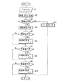
図2は、直進時でかつ高速走行時(例えば車速80km/hを超える車速域)に設定される光度設定例である。各光源の光度を照射率で示してあり、照射率は、各光源への印加電圧が最大値となるときが100%とされる。つまり、照射率が小さい(印加電圧が小さい)ほど光度が小さいものとなる。図2の設定例では、もっとも車幅方向中央よりとなる第1領域用光源R1、R2(L3、L4)の光度が照射率で100%とされる。また、第2領域用光源R3(L2)の光度および第3領域用光源R4(L1)の光度がそれぞれ照射率で25%とされる。図2の設定において、車幅方向中央よりの光度が極めて高くされて、前方かつ遠方の視認性が極めて良好となる。また、相対的に車幅方向外側を照射する第2領域用光源R3(L2)および第3領域用光源R4(L1)は、消灯されることなく、点灯されているために、路肩に存在する道路標識の視認性も十分に確保されることになる。 FIG. 2 is a light intensity setting example that is set when traveling straight and traveling at a high speed (for example, a vehicle speed range exceeding a vehicle speed of 80 km / h). The luminous intensity of each light source is indicated by the irradiation rate, and the irradiation rate is set to 100% when the applied voltage to each light source becomes the maximum value. That is, the smaller the irradiation rate (the smaller the applied voltage), the smaller the luminous intensity. In the setting example of FIG. 2, the luminous intensity of the first region light sources R1 and R2 (L3 and L4) that are closest to the center in the vehicle width direction is 100% in terms of irradiation rate. Further, the luminous intensity of the second area light source R3 (L2) and the luminous intensity of the third area light source R4 (L1) are each 25% in terms of irradiation rate. In the setting of FIG. 2, the light intensity from the center in the vehicle width direction is made extremely high, and visibility in the front and the far direction becomes extremely good. In addition, the second region light source R3 (L2) and the third region light source R4 (L1) that relatively illuminate the outside in the vehicle width direction are turned on without being turned off, and thus exist on the road shoulder. The visibility of road signs will be sufficiently secured.
図3は、直進時でかつ中速走行時(例えば40〜80km/hの範囲の車速域)に設定される光度設定例である。図3の設定例では、もっとも所定方向中央よりとなる第1領域用光源R1、R2(L3、L4)の光度が、高速走行時よりも低下されて、照射率で75%とされる。第2領域用光源R3(L2)の光度は、照射率で50%とされて、高速走行時に比して光度が高められた状態とされる。第3領域用光源R4(L1)の光度は、照射率で25%とされて、高速走行時と変化なしとされる。この図3の設定例では、車幅方向中央から外側にかけての広い範囲での光度が十分に確保され、もっとも車幅方向外側の領域も照射されて、中速域で好ましい照射態様とされる。 FIG. 3 is a light intensity setting example that is set when traveling straight and traveling at medium speed (for example, a vehicle speed range of 40 to 80 km / h). In the setting example of FIG. 3, the luminous intensity of the first region light sources R1 and R2 (L3, L4) that is most from the center in the predetermined direction is lowered as compared with that during high-speed traveling, and the irradiation rate is 75%. The light intensity of the second region light source R3 (L2) is 50% in terms of irradiation rate, and is in a state where the light intensity is increased as compared with high speed traveling. The light intensity of the third region light source R4 (L1) is 25% in terms of irradiation rate, and is unchanged from that during high-speed travel. In the setting example of FIG. 3, the light intensity in a wide range from the center in the vehicle width direction to the outside is sufficiently secured, and the region outside in the vehicle width direction is also irradiated, which is a preferable irradiation mode in the medium speed range.
図4は、直進時でかつ低速走行時(例えば40km/h未満の車速域)に設定される光度設定例である。図4の設定例では、もっとも所定方向中央よりとなる第1領域用光源R1、R2(L3、L4)の光度が、中速走行時よりも低下されて、照射率で50%とされる。第2領域用光源R3(L2)の光度は、照射率で50%とされて、中速走行時と同じとされる。第3領域用光源R4(L1)の光度は、照射率で50%とされて、中速走行時に比して光度が高められている。これにより、遠方の照射はできないものの、車幅方向中央から外側にかけての広い範囲に渡って十分な光度が確保されて、低速域で好ましい照射態様とされる。 FIG. 4 is a light intensity setting example that is set when traveling straight and traveling at a low speed (for example, a vehicle speed range of less than 40 km / h). In the setting example of FIG. 4, the luminous intensity of the first region light sources R1 and R2 (L3 and L4), which is the most centered in the predetermined direction, is lower than that during medium speed traveling, and the irradiation rate is 50%. The luminous intensity of the second region light source R3 (L2) is 50% in terms of irradiation rate, which is the same as during medium speed traveling. The light intensity of the third region light source R4 (L1) is 50% in terms of irradiation rate, and the light intensity is higher than that during medium speed traveling. Thereby, although long-distance irradiation cannot be performed, sufficient light intensity is ensured over a wide range from the center in the vehicle width direction to the outside, and a preferable irradiation mode is achieved in a low speed region.
図5は、車両1が左旋回時のときを示す。この左旋回時では、旋回方向となる左側に近い側から遠い側に順に、光度が順次低くなるように設定される。すなわち、もっとも左側を照射する領域用光源R1(L1)の光度が照射率で100%とされ、領域用光源R2(L2)の光度が照射率で75%とされ、領域用光源R3(L3)の光度が照射率で50%とされ、領域用光源R4(L4)の光度が照射率で25%とされる。なお、右旋回時には、上述の場合とは左右対称の照射態様とされて、右側を照射する領域用光源ほどその光度が高くされる。このように、旋回方向を照射する領域用光源を優先して明るくすることにより、旋回進行方向の視認性を十分に高めることができる。なお、図6のような設定は、車速と無関係に設定される(旋回方向の視認性確保を優先)。 FIG. 5 shows the time when the vehicle 1 is turning left. During the left turn, the light intensity is set to decrease sequentially from the side closer to the left side in the turning direction to the far side. That is, the luminous intensity of the region light source R1 (L1) that irradiates the leftmost side is set to 100% in terms of irradiation rate, the luminous intensity of the region light source R2 (L2) is set to 75% in terms of irradiation rate, and the region light source R3 (L3) Is 50% in terms of irradiation rate, and the luminous intensity of the region light source R4 (L4) is 25% in terms of irradiation rate. Note that when turning right, the illumination mode is bilaterally symmetric with respect to the above-described case, and the luminous intensity of the region light source that illuminates the right side is increased. Thus, by making the area light source that irradiates the turning direction preferentially bright, the visibility in the turning direction can be sufficiently enhanced. The setting shown in FIG. 6 is set regardless of the vehicle speed (priority is ensured in the visibility in the turning direction).
図7は、前述した制御を行うために、車両1に構成された制御系統例が示される。この図7において、Uは、マイクロコンピュータを利用して構成されたコントローラ(制御ユニット)である。コントローラUには、車速を検出する車速センサ11からの信号と、ハンドル舵角を検出する舵角センサ12からの信号が入力される他、マニュアル操作されて光度変更制御を実行するか否かの選択を行うオートライトスイッチ13からの信号が入力される。勿論、コントローラUによって、左右の前照灯2L、2Rの光度制御が行われる。
FIG. 7 shows an example of a control system configured in the vehicle 1 in order to perform the above-described control. In FIG. 7, U is a controller (control unit) configured using a microcomputer. The controller U is supplied with a signal from the
図8は、コントローラUの光度変更の制御例を示すフローチャートであり、以下このフローチャートについて説明する。なお、以下の説明でQはステップを示し、またオートライトスイッチ13がONされて、光度変更制御を実行することを要求していることを前提としている(オートライトスイッチ13がオフのときは、光度変更制御はなし)。 FIG. 8 is a flowchart showing a control example of the light intensity change of the controller U. This flowchart will be described below. In the following description, Q indicates a step, and it is assumed that the auto light switch 13 is turned on and it is requested to execute the light intensity change control (when the auto light switch 13 is off, There is no intensity change control).
まず、Q1において、車速センサ11と舵角センサ12からの信号が読み込まれる。次いで、Q2において、舵角センサ12での検出結果に基づいて、直線路であるのかカーブであるのかの判定が行われる。なお、このQ2での判定は、例えばナビゲーション装置の地図情報に基づいて行うこともできる。
First, in Q1, signals from the
この後、Q3において、Q2の判定結果に基づいて、現在直進走行中であるか否かが判別される。このQ3の判別でYESのときは、Q4において、車両1の実際の速度がどのの速度域にあるのかが判定される。この後、Q5において、低速走行中であるか否かが判別される。このQ5の判別でYESのときは、Q6において、図4に示すような光度設定とされる。 Thereafter, in Q3, it is determined whether the vehicle is currently traveling straight ahead based on the determination result of Q2. If the determination in Q3 is YES, in Q4, it is determined in which speed range the actual speed of the vehicle 1 is. Thereafter, in Q5, it is determined whether or not the vehicle is traveling at a low speed. If YES in Q5, the light intensity is set as shown in FIG. 4 in Q6.
Q6の後、あるいはQ5の判別でNOのときは、Q7において、中速走行中であるか否かが判別される。このQ7の判別でYESのときは、Q8において、図3に示すような光度設定とされる。 After Q6 or when NO in Q5, it is determined in Q7 whether the vehicle is traveling at medium speed. If YES in Q7, the light intensity is set as shown in FIG. 3 in Q8.
Q8の後、あるいはQ7の判別でNOのときは、Q9において、高速走行中であるか否かが判別される。このQ9の判別でYESのときは、Q10において、図2に示すような光度設定とされる。 After Q8 or when NO in Q7, it is determined in Q9 whether the vehicle is traveling at high speed. When the determination at Q9 is YES, the light intensity is set at Q10 as shown in FIG.
Q10の後、あるいはQ9の判別でNOのときは、Q1にリターンされる。また、Q3の判別でNOのとき、つまり旋回中のときは、Q11において、図6に示すような光度設定とされる(左旋回のときで、右旋回のときは図6に示す光度設定が左右逆の関係となる)。 After Q10 or when NO in Q9, the process returns to Q1. When NO in Q3, that is, when the vehicle is turning, the light intensity is set as shown in FIG. 6 in Q11 (the light intensity setting shown in FIG. 6 when turning left and turning right). Is a reverse relationship).
ここで、車速の変化に伴って光度変化を行うときは、相対的にゆっくりと行って、一気に光度変化させないようにするのが好ましい。すなわち、運転者に対して、部分的に光度が大きく変化することを感じさせないようにして、光度変化に伴う違和感を与えないようにする上で好ましいものとなる。逆に、旋回時には、図6に示すような光度設定をへてすみやかに変更することが好ましい。つまり、旋回時に対応するための光度変更は、直進時における車速に応じた光度変更よりも、光度変更速度を速めるのが好ましいものである。 Here, when the luminous intensity is changed with the change in the vehicle speed, it is preferable that the luminous intensity is changed relatively slowly so that the luminous intensity is not changed at a stretch. In other words, it is preferable to prevent the driver from feeling that the light intensity changes greatly in part and not to give a sense of incongruity due to the light intensity change. On the other hand, when turning, it is preferable to change the light intensity setting as shown in FIG. 6 immediately. That is, it is preferable that the luminous intensity change for responding to turning is faster than the luminous intensity change according to the vehicle speed when traveling straight ahead.
以上実施形態について説明したが、本発明は、実施形態に限定されるものではなく、特許請求の範囲の記載された範囲において適宜の変更が可能である。領域用光源を構成する各光源は、一定のものに固定することなく、変更することもできる。例えば、右前照灯2Rを例に説明すると、高速走行時にはR1、R2が第1領域用光源とされているが、中速走行時には、第1領域用光源をR1のみに設定して、領域用光源R2を第2領域用光源として仕分けしてもよい。車速に応じて光度の変更制御を行う場合、車速にヒステリシスを設定して、光度変更が行われる車速付近での微妙な車速の変化では、光度変更が行われないようにすることもできる。
Although the embodiments have been described above, the present invention is not limited to the embodiments, and appropriate modifications can be made within the scope of the claims. Each light source constituting the area light source can be changed without being fixed to a fixed one. For example, the
先行車両や対向車両が存在するときは、図2〜図4、図6の設定例から、先行車両や対向車両が存在する領域を照射する光源のみを減光させるようにしてもよい(この減光からの復帰つまり増光は、旋回時と同様にすみやかに行うのが好ましい)。勿論、本発明の目的は、明記されたものに限らず、実質的に好ましいあるいは利点として表現されたものを提供することをも暗黙的に含むものである。 When there is a preceding vehicle or an oncoming vehicle, only the light source that irradiates the area where the preceding vehicle or the oncoming vehicle exists may be dimmed from the setting examples in FIGS. (Return from light, that is, brightening is preferably performed as quickly as when turning). Of course, the object of the present invention is not limited to what is explicitly stated, but also implicitly includes providing what is substantially preferred or expressed as an advantage.
本発明は、運転者の視認性確保の上で好適な光度変更制御となる。 The present invention provides light intensity change control suitable for ensuring driver visibility.
1:車両
2R、2L:前照灯
11:車速センサ
12:舵角センサ
U:コントローラ
R1、R2(L3、L4):領域用光源(第1領域用光源)
R3(L2):領域用光源(第2領域用光源)
R4(L1):領域用光源(第3領域用光源)
1:
R3 (L2): area light source (second area light source)
R4 (L1): area light source (third area light source)
Claims (9)
前記複数の光源を左右方向に照射範囲を相違させた第1領域用光源と第2領域用光源と第3領域用光源と分けて、車速に応じて各領域用光源の光度を個々独立して制御する光度制御手段を備え、
前記光度制御手段は、前記3つの領域用光源について、消灯させることなく減光を行う減光制御と増光を行う増光制御と該減光および増光よりも光度変化が少ない光度制御となる中間制御とに仕分けした光度制御を行い、
前記光度制御手段は、車両の旋回中においては、前記複数の光源の光度を、旋回方向に近い光源ほど高める、
ことを特徴とする車両の前照灯制御装置。 A headlamp control device for a vehicle having a plurality of three or more light sources in which a headlamp for illuminating the front of the vehicle has different illumination ranges in the left-right direction,
The plurality of light sources are divided into a first region light source, a second region light source, and a third region light source having different irradiation ranges in the left-right direction, and the light intensity of each region light source is independently set according to the vehicle speed. A light intensity control means for controlling,
The luminous intensity control means includes a dimming control that performs dimming without turning off the light for the three regions, a dimming control that performs a brightening, and an intermediate control that performs a luminous intensity control with less luminous intensity change than the dimming and brightening. It performs a light intensity control was sorted into,
The light intensity control means increases the light intensity of the plurality of light sources as the light source is closer to the turning direction during turning of the vehicle.
A vehicle headlamp control device characterized by the above.
前記増光制御されるときの増光量と、前記減光制御されるときの減光量とが同一とされている、ことを特徴とする車両の前照灯制御装置。 In claim 1,
2. A vehicle headlamp control device according to claim 1, wherein the light increase amount when the light increase control is performed is the same as the light decrease amount when the light decrease control is performed.
前記中間制御での光度の変化量が0とされている、ことを特徴とする車両の前照灯制御装置。 In claim 1 or claim 2,
A vehicle headlamp control device according to claim 1, wherein the amount of change in luminous intensity in the intermediate control is zero.
前記増光制御されるときの光度変化速度と前記減光制御されるときの光度変化速度とが略同一とされている、ことを特徴とする車両の前照灯制御装置。 In any one of Claims 1 thru | or 3,
The vehicle headlamp control device according to claim 1, wherein a luminous intensity change rate when the dimming control is performed is substantially the same as a luminous intensity change rate when the dimming control is performed.
第1領域用光源がもっとも車体中央側部分を照射し、第3領域用光源がもっとも車幅方向外側部分を照射し、第2領域用光源が第1領域用光源と第3領域用光源との間を照射するように設定され、
前記光度制御手段は、低速時から中速時へ移行したときに、前記第3領域用光源を減光制御し、前記第1領域用光源を増光制御し、前記第2領域用光源を前記中間制御し、
前記光度制御手段は、中速時から低速時へ移行したときに、前記第3領域用光源を増光制御し、前記第1領域用光源を減光制御し、前記第2領域用光源を前記中間制御する、
ことを特徴とする車両の前照灯制御装置。 In any one of Claims 1 thru | or 4,
The light source for the first region irradiates the vehicle body center side portion, the light source for the third region radiates the outermost portion in the vehicle width direction, and the light source for the second region is between the light source for the first region and the light source for the third region. Set to illuminate
The luminous intensity control unit performs dimming control on the light source for the third region, control for increasing the light source for the first region, and control the light source for the second region to the intermediate when the transition from the low speed to the medium speed is performed. Control
The luminous intensity control means controls the light increase for the third region light source, controls the light reduction for the first region light source, and controls the light source for the second region to the intermediate when the medium speed shifts to the low speed. Control,
A vehicle headlamp control device characterized by the above.
第1領域用光源がもっとも車体中央側部分を照射し、第3領域用光源がもっとも車幅方向外側部分を照射し、第2領域用光源が第1領域用光源と第3領域用光源との間を照射するように設定され、
前記光度制御手段は、中速時から高速時へ移行したときに、前記第3領域用光源を前記中間制御し、前記第1領域用光源を増光制御し、前記第2領域用光源を前記減光制御し、
前記光度制御手段は、高速時から中速時へ移行したときに、前記第3領域用光源を前記中間制御し、前記第1領域用光源を減光制御し、前記第2領域用光源を前記増光制御する、
ことを特徴とする車両の前照灯制御装置。 In any one of Claims 1 thru | or 5,
The light source for the first region irradiates the vehicle body center side portion, the light source for the third region radiates the outermost portion in the vehicle width direction, and the light source for the second region is between the light source for the first region and the light source for the third region. Set to illuminate
The luminous intensity control means performs the intermediate control of the light source for the third area, the light intensity control of the light source for the first area, and the light source for the second area when the transition from medium speed to high speed is performed. Light control,
The luminous intensity control means performs the intermediate control of the light source for the third region, the dimming control of the light source for the first region, and the light source for the second region when the transition from the high speed to the medium speed is performed. Brightening control,
A vehicle headlamp control device characterized by the above.
前記複数の光源が、前記第1領域用光源、前記第2領域用光源及び前記第3領域用光源を構成するものとして固定されている、ことを特徴とする車両の前照灯制御装置。 In any one of Claims 1 thru | or 6,
The vehicle headlamp control device according to claim 1 , wherein the plurality of light sources are fixed to constitute the first region light source, the second region light source, and the third region light source.
前記第1領域用光源、前記第2領域用光源、前記第3領域用光源を構成する光源が、前記複数の光源の中で変更される、ことを特徴とする車両の前照灯制御装置。 In any one of Claims 1 thru | or 6,
The vehicle headlamp control device according to claim 1, wherein light sources constituting the light source for the first region, the light source for the second region, and the light source for the third region are changed among the plurality of light sources .
前記光度制御手段は、直進時における光度の変化速度よりも、旋回中における光度の変化速度を大きくする、ことを特徴とする車両の前照灯制御装置。
In claim 1,
The vehicle headlamp control device according to claim 1, wherein the luminous intensity control means increases a luminous intensity change rate during a turn rather than a luminous intensity change rate during straight traveling.
Priority Applications (1)
| Application Number | Priority Date | Filing Date | Title |
|---|---|---|---|
| JP2013252659A JP6201700B2 (en) | 2013-12-06 | 2013-12-06 | Vehicle headlight control device |
Applications Claiming Priority (1)
| Application Number | Priority Date | Filing Date | Title |
|---|---|---|---|
| JP2013252659A JP6201700B2 (en) | 2013-12-06 | 2013-12-06 | Vehicle headlight control device |
Publications (2)
| Publication Number | Publication Date |
|---|---|
| JP2015107780A JP2015107780A (en) | 2015-06-11 |
| JP6201700B2 true JP6201700B2 (en) | 2017-09-27 |
Family
ID=53438508
Family Applications (1)
| Application Number | Title | Priority Date | Filing Date |
|---|---|---|---|
| JP2013252659A Active JP6201700B2 (en) | 2013-12-06 | 2013-12-06 | Vehicle headlight control device |
Country Status (1)
| Country | Link |
|---|---|
| JP (1) | JP6201700B2 (en) |
Families Citing this family (3)
| Publication number | Priority date | Publication date | Assignee | Title |
|---|---|---|---|---|
| JP2016107880A (en) * | 2014-12-08 | 2016-06-20 | スタンレー電気株式会社 | Vehicular headlight |
| FR3038697B1 (en) * | 2015-07-10 | 2017-08-11 | Valeo Vision | METHOD FOR CONTROLLING A BRIGHT BEAM AND LIGHTING AND / OR SIGNALING MODULE THEREOF |
| JP7002963B2 (en) * | 2018-02-22 | 2022-01-20 | スタンレー電気株式会社 | Vehicle lighting |
Family Cites Families (7)
| Publication number | Priority date | Publication date | Assignee | Title |
|---|---|---|---|---|
| JP2955199B2 (en) * | 1994-12-29 | 1999-10-04 | 本田技研工業株式会社 | Variable light distribution headlamp device |
| JP3933895B2 (en) * | 2001-08-08 | 2007-06-20 | 株式会社小糸製作所 | Vehicle headlamp device |
| JP4266175B2 (en) * | 2004-03-01 | 2009-05-20 | 株式会社小糸製作所 | Vehicle lighting device |
| JP4333419B2 (en) * | 2004-03-12 | 2009-09-16 | 市光工業株式会社 | Vehicle headlight system |
| JP4931720B2 (en) * | 2007-07-26 | 2012-05-16 | 株式会社小糸製作所 | Lighting control device for vehicle lamp |
| JP2009179113A (en) * | 2008-01-29 | 2009-08-13 | Koito Mfg Co Ltd | Head lamp device for vehicle and its control method |
| JP5869835B2 (en) * | 2011-10-12 | 2016-02-24 | 株式会社小糸製作所 | Vehicle headlight control system |
-
2013
- 2013-12-06 JP JP2013252659A patent/JP6201700B2/en active Active
Also Published As
| Publication number | Publication date |
|---|---|
| JP2015107780A (en) | 2015-06-11 |
Similar Documents
| Publication | Publication Date | Title |
|---|---|---|
| JP5564524B2 (en) | Sub headlight unit and sub headlight system for a vehicle turning in a lean position, and a vehicle turning in a lean position | |
| JP6761244B2 (en) | vehicle | |
| JP6402752B2 (en) | Vehicle lighting device | |
| JP2001213227A (en) | Lighting system for vehicle | |
| JP2015033944A (en) | Lighting control device for headlight of vehicle, and headlight system of vehicle | |
| US8757853B2 (en) | Method for controlling a vehicle headlamp | |
| JP2007276704A (en) | Lighting control system | |
| US20020196634A1 (en) | Apparatus for a motor vehicle, for lighting bends negotiated by the vehicle | |
| JP2017119474A (en) | vehicle | |
| WO2014038637A1 (en) | Vehicular headlight control device and method | |
| JP2013230772A (en) | Headlight unit and headlight system for use in vehicle that lean into turn and vehicle that lean into turn | |
| JP2014000875A (en) | Sub-headlight unit, headlight unit and headlight system for vehicles to turn in lean positions, and vehicle for turning in lean positions | |
| JP2008195335A (en) | Lamp lighting control system and lamp lighting control method | |
| JP6201700B2 (en) | Vehicle headlight control device | |
| JP4180535B2 (en) | Vehicle lighting device | |
| JP2007246060A (en) | Headlight device for vehicle | |
| JP2013230773A (en) | Sub headlight unit and sub headlight system for use in vehicle that leans into turn, and vehicle that leans into turn | |
| JP2013067288A (en) | Passing system of vehicle headlight | |
| JP2009012553A (en) | Lighting unit for vehicle | |
| JP2006273092A (en) | Vehicle headlight system | |
| JP6005415B2 (en) | Vehicle cornering lamp | |
| JP6992428B2 (en) | Vehicle lighting | |
| JP2014054889A (en) | Side lamp system | |
| JP4534815B2 (en) | Lighting control device for additional lamp for vehicle | |
| JP6508081B2 (en) | Vehicle headlight system |
Legal Events
| Date | Code | Title | Description |
|---|---|---|---|
| A621 | Written request for application examination |
Free format text: JAPANESE INTERMEDIATE CODE: A621 Effective date: 20160225 |
|
| A977 | Report on retrieval |
Free format text: JAPANESE INTERMEDIATE CODE: A971007 Effective date: 20161226 |
|
| A131 | Notification of reasons for refusal |
Free format text: JAPANESE INTERMEDIATE CODE: A131 Effective date: 20170110 |
|
| A521 | Written amendment |
Free format text: JAPANESE INTERMEDIATE CODE: A523 Effective date: 20170310 |
|
| TRDD | Decision of grant or rejection written | ||
| A01 | Written decision to grant a patent or to grant a registration (utility model) |
Free format text: JAPANESE INTERMEDIATE CODE: A01 Effective date: 20170801 |
|
| A61 | First payment of annual fees (during grant procedure) |
Free format text: JAPANESE INTERMEDIATE CODE: A61 Effective date: 20170814 |
|
| R150 | Certificate of patent or registration of utility model |
Ref document number: 6201700 Country of ref document: JP Free format text: JAPANESE INTERMEDIATE CODE: R150 |