JP6201459B2 - Project rescheduling method and program - Google Patents
Project rescheduling method and program Download PDFInfo
- Publication number
- JP6201459B2 JP6201459B2 JP2013138771A JP2013138771A JP6201459B2 JP 6201459 B2 JP6201459 B2 JP 6201459B2 JP 2013138771 A JP2013138771 A JP 2013138771A JP 2013138771 A JP2013138771 A JP 2013138771A JP 6201459 B2 JP6201459 B2 JP 6201459B2
- Authority
- JP
- Japan
- Prior art keywords
- work
- project
- urgency
- reschedule
- date
- Prior art date
- Legal status (The legal status is an assumption and is not a legal conclusion. Google has not performed a legal analysis and makes no representation as to the accuracy of the status listed.)
- Expired - Fee Related
Links
- 238000000034 method Methods 0.000 title claims description 42
- 238000007726 management method Methods 0.000 description 25
- 238000010586 diagram Methods 0.000 description 15
- 238000012545 processing Methods 0.000 description 14
- 238000004891 communication Methods 0.000 description 6
- 238000003825 pressing Methods 0.000 description 5
- 230000003111 delayed effect Effects 0.000 description 4
- 238000011161 development Methods 0.000 description 4
- 238000012552 review Methods 0.000 description 4
- 230000015556 catabolic process Effects 0.000 description 2
- 230000004044 response Effects 0.000 description 2
- 238000012790 confirmation Methods 0.000 description 1
- 230000001934 delay Effects 0.000 description 1
- 239000000284 extract Substances 0.000 description 1
- 230000006870 function Effects 0.000 description 1
- 230000010365 information processing Effects 0.000 description 1
- 238000012986 modification Methods 0.000 description 1
- 230000004048 modification Effects 0.000 description 1
- 238000012946 outsourcing Methods 0.000 description 1
- 239000004065 semiconductor Substances 0.000 description 1
- 238000004904 shortening Methods 0.000 description 1
Images


Landscapes
- Management, Administration, Business Operations System, And Electronic Commerce (AREA)
Description
本発明は、プロジェクトのリスケジュールに関する。 The present invention relates to project rescheduling.
従来より、システムを用いて、情報処理に関する開発プロジェクトをスケジュールすることが行われている。開発の依頼者である顧客の都合等による開発要件の追加、作業遅延などにより、初期にスケジュールしたプロジェクトが、予定通りに進捗するとは限らない。 Conventionally, a development project related to information processing is scheduled using a system. Due to the addition of development requirements due to the circumstances of the client who is the client of the development, work delay, etc., the initially scheduled project may not always progress as planned.
スケジュールの見直しに関して、プロジェクトの納期とプロジェクトの完了予測日の差から遅延量を算出し、遅延が予測される場合は、作業工程の優先度を変更したり、他プロジェクトの納期等を遵守できるように計画を自動的に変更する技術、同一工程について過去実績期間と現在設定期間とを比べ、実績期間が短ければ設定期間を短縮する技術等が提案されている。 Regarding the review of the schedule, the amount of delay is calculated from the difference between the delivery date of the project and the expected completion date of the project. If the delay is predicted, the priority of the work process can be changed and the delivery date of other projects can be observed. A technique for automatically changing the plan, a technique for comparing the past performance period and the current setting period for the same process, and shortening the setting period if the performance period is short have been proposed.
開発するプロジェクトは、複数の作業で構成され、例えば、標準WBS(Work Breakdown structure:作業分割構成)に基づいて各プロジェクトについて複数の作業が設定される。設定された作業は全て実施すべき作業であり、これを省略することは品質の低下につながる。 A project to be developed is composed of a plurality of operations. For example, a plurality of operations are set for each project based on a standard WBS (Work Breakdown structure). All the set tasks are tasks that should be performed, and omitting them leads to a decrease in quality.
プロジェクトの納期(システム稼働日)までの期間において、未完了の作業が存在する場合には、各プロジェクトを管理するPM(プロジェクトマネージャ)は、未完了の作業のうち、システム稼働後の作業としてリスケジュール可能な不急の作業を正確に見極めて、納期前後のスケジュールを見直すことが必要な場合がる。 If there are unfinished work in the period up to the project delivery date (system working day), the PM (project manager) managing each project will reset the unfinished work as work after system operation. It may be necessary to accurately identify urgent work that can be scheduled and review the schedule before and after delivery.
不急の作業とは、本来実施する必要があるが、幾つかの条件によってはシステム稼働後に実施しても問題のない作業である。不急の作業の見極めは難しく、経験の少ないPMには負担となっている。 An urgent task is a task that should be performed originally, but it can be performed after the system is operated depending on some conditions. It is difficult to identify urgent work, and it is a burden for PMs with little experience.
上述した技術では、プロジェクトの納期までの作業工程の調整を行うものであり、不急の作業を見極めることができないため、納期直前のスケジュール調整を行うPMの負担を軽減できない。 In the above-described technique, the work process is adjusted until the delivery date of the project, and the urgent work cannot be determined. Therefore, it is not possible to reduce the burden on the PM that performs the schedule adjustment immediately before the delivery date.
1つの側面において、本発明の目的は、プロジェクトにおいて未完了の作業をリスケジュールすることである。 In one aspect, an object of the present invention is to reschedule incomplete work in a project.
本実施例の一態様によれば、コンピュータによって実行される複数の作業を有するプロジェクトのリスケジュール方法であって、前記作業毎の実績を示す作業実績情報を記憶した記憶部を参照して、指定されたプロジェクトに係る該作業実績情報に基づいて未完了の作業を抽出し、前記抽出された未完了の作業毎に、過去に該作業をリスケジュールしたプロジェクトマネージャに対して、リスケジュールした割合と該プロジェクトマネージャの熟練度とを積和した値を、プロジェクトマネージャの総数で割ることによって、前記プロジェクトの納期後に作業可能な程度を示す不急度を算出し、前記未完了の作業毎に前記不急度を対応付けた不急度一覧表を作成して記憶部に記憶し、前記不急度一覧表に基づいて、前記未完了の作業を前記納期後にリスケジュールしたリスケジュール案を作成し、前記リスケジュール案を表示装置に表示させる。 According to one aspect of the present embodiment, a method for rescheduling a project having a plurality of operations executed by a computer, wherein the designation is made with reference to a storage unit storing work performance information indicating a result of each work. The unscheduled work is extracted based on the work performance information related to the project that has been rescheduled, and the rescheduled ratio for each project work that has been rescheduled in the past, The value obtained by multiplying the sum of the proficiency level of the project manager by the total number of project managers is calculated to calculate the degree of urgency indicating the degree of work that can be performed after the delivery date of the project. An urgency list associated with urgency is created and stored in the storage unit, and the unfinished work is transferred to the delivery date based on the urgency list To create a rescheduling proposal was rescheduled to display the rescheduling draft display device.
また、上記課題を解決するための手段として、上記手順をコンピュータに実行させるリスケジュールプログラム、そのリスケジュールプログラムを記録した記録媒体、及び上記プロジェクトのリスケジュール方法を行うプロジェクト管理装置とすることもできる。 Further, as means for solving the above-described problems, a reschedule program for causing a computer to execute the above procedure, a recording medium on which the reschedule program is recorded, and a project management apparatus that performs the project rescheduling method can be used. .
本実施例の一態様によれば、プロジェクトにおいて未完了の作業をリスケジュールすることができる。 According to one aspect of the present embodiment, it is possible to reschedule incomplete work in a project.
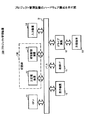
以下、本発明の実施の形態を図面に基づいて説明する。本実施の形態におけるプロジェクト管理装置は、図1に示すようなハードウェア構成を有する。図1は、プロジェクト管理装置のハードウェア構成を示す図である。図1において、プロジェクト管理装置100は、コンピュータによって制御される端末であって、CPU(Central Processing Unit)11と、主記憶装置12と、補助記憶装置13と、入力装置14と、表示装置15と、通信I/F(インターフェース)17と、ドライブ装置18とを有し、バスBに接続される。
Hereinafter, embodiments of the present invention will be described with reference to the drawings. The project management apparatus in the present embodiment has a hardware configuration as shown in FIG. FIG. 1 is a diagram illustrating a hardware configuration of the project management apparatus. In FIG. 1, a
CPU11は、主記憶装置12に格納されたプログラムに従ってプロジェクト管理装置100を制御する。主記憶装置12には、RAM(Random Access Memory)、ROM(Read Only Memory)等が用いられ、CPU11にて実行されるプログラム、CPU11での処理に必要なデータ、CPU11での処理にて得られたデータ等を格納する。また、主記憶装置12の一部の領域が、CPU11での処理に利用されるワークエリアとして割り付けられている。
The
補助記憶装置13には、ハードディスクドライブが用いられ、各種処理を実行するためのプログラム等のデータを格納する。補助記憶装置13に格納されているプログラムの一部が主記憶装置12にロードされ、CPU11に実行されることによって、各種処理が実現される。記憶部130は、主記憶装置12及び/又は補助記憶装置13を有する。
The
入力装置14は、マウス、キーボード等を有し、ユーザがプロジェクト管理装置100による処理に必要な各種情報を入力するために用いられる。表示装置15は、CPU11の制御のもとに必要な各種情報を表示する。通信I/F17は、例えばインターネット、LAN(Local Area Network)等に接続し、外部装置との間の通信制御をするための装置である。通信I/F17による通信は無線又は有線に限定されるものではない。
プロジェクト管理装置100によって行われる処理を実現するプログラムは、例えば、CD−ROM(Compact Disc Read-Only Memory)等の記憶媒体19によってプロジェクト管理装置100に提供される。
The
A program for realizing the processing performed by the
ドライブ装置18は、ドライブ装置18にセットされた記憶媒体19(例えば、CD−ROM等)とプロジェクト管理装置100とのインターフェースを行う。
The
また、記憶媒体19に、後述される本実施の形態に係る種々の処理を実現するプログラムを格納し、この記憶媒体19に格納されたプログラムは、ドライブ装置18を介してプロジェクト管理装置100にインストールされる。インストールされたプログラムは、プロジェクト管理装置100により実行可能となる。
In addition, the
尚、プログラムを格納する媒体としてCD−ROMに限定するものではなく、コンピュータが読み取り可能な媒体であればよい。コンピュータ読取可能な記憶媒体として、CD−ROMの他に、DVDディスク、USBメモリ等の可搬型記録媒体、フラッシュメモリ等の半導体メモリであっても良い。 The medium for storing the program is not limited to a CD-ROM, and any medium that can be read by a computer may be used. As a computer-readable storage medium, in addition to a CD-ROM, a portable recording medium such as a DVD disk or a USB memory, or a semiconductor memory such as a flash memory may be used.
本実施の形態におけるプロジェクト管理装置100は、センタ型アウトソーシングサービスとしてプロジェクトを管理するシステムであり、例えば、標準WBS(Work Breakdown structure:作業分割構成)の適用により、作業進捗の管理を支援する。
The
プロジェクト管理装置100では、プロジェクトが遅延した場合に、不急の作業を特定しリスケジュールすることを可能とする。プロジェクトの不急の作業を、過去の作業実績から判断し、その作業を納期後(例えば、システム稼働後)にリスケジュールすることを可能とする。
The
不急の作業例として、本来ならばシステム稼働までにシステムバックアップの自動化ツールを作成して動かす必要があるが、どうしてもシステム稼働日までに作成が間に合わない。その際、自動化ツールが完成するまでの間、バックアップは手動で実施するといった対応が考えられる。そしてシステム稼働後、余裕ができた段階で自動化ツールを作成する。 As an urgent work example, it is necessary to create and run a system backup automation tool by the time the system is operating, but the creation is not in time by the system operating date. At that time, it may be possible to perform backup manually until the automation tool is completed. Then, after the system is operating, create an automated tool when there is room.
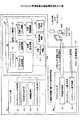
図2は、プロジェクト管理装置の機能構成例を示す図である。図2において、プロジェクト管理装置100は、データベース(DB)31と、スケジュール部40と、リスケジュール部50とを有する。
FIG. 2 is a diagram illustrating a functional configuration example of the project management apparatus. In FIG. 2, the
スケジュール部40は、プロジェクトを構成する複数の作業のスケジュールを行う処理部であり、マスタスケジュール作成部41と、担当者割り当て部42と、実績管理部43と、マスタスケジュール表示部44等を有する。
The
マスタスケジュール作成部41は、プロジェクト基本情報34に新たなプロジェクトを登録し、作業基本情報37に、新プロジェクトを構成する各作業を登録する等によってマスタスケジュールを作成する。マスタスケジュールは、プロジェクトの納期までの各作業のスケジュールを示す。
The master
担当者割り当て部42は、プロジェクト毎、作業毎に担当者を割り当てる。担当者割り当て部42は、担当ユーザリンク情報36によって、プロジェクト及び作業と担当者とを関連付ける。また、担当者割り当て部42は、役割マップ情報23を用いて、割り当てた担当ユーザと、割り当てられたプロジェクトでの役割とを対応付ける。
The person-in-
実績管理部43は、各プロジェクト、各作業の実績を管理する。実績管理部43は、プロジェクト実績情報35を用いてプロジェクトの実績を管理し、作業実績情報38を用いて作業の実績を管理する。
The
マスタスケジュール表示部44は、DB31を用いて、プロジェクトマネージャPM2によって指定されたプロジェクトのマスタスケジュールを表示装置15に表示する。
The master
リスケジュール部50は、プロジェクトマネージャPM2のリスケジュール案作成指示に応じて、プロジェクトのリスケジュールを行う処理部であり、不急度判定部51と、リスケジュール案作成部52とを有する。
The rescheduling
リスケジュール部50における処理において、対象プロジェクト情報61、対象作業情報62、不急度一覧表63が内部データ60として記憶部130に保持される。内部データ60は、リスケジュール部50における処理中に有効なデータであり、処理の終了によって初期化される。
In the process in the
対象プロジェクト情報61は、リスケジュール対象のプロジェクトに関する情報であり、プロジェクトマネージャPM2によるスケジュールの表示要求等によって指定されたプロジェクトに関する。
The
対象作業情報62は、指定されたプロジェクトを構成する1以上の作業に関する情報であり、各作業に対応付けて少なくとも作業の未完了/完了のステータスを管理するテーブルである。
The
不急度一覧表63は、対象作業情報62において未完了の作業に関して、各作業に対応付けて少なくとも不急度を示すテーブルである。不急度は、プロジェクトの納期後に作業可能な程度を示す。不急度がゼロ又はゼロに近い程、プロジェクトの納期後の作業は不可であることを示し、納期後へのリスケジュールできないことを意味する。また、不急度が高い程、プロジェクトの納期後に作業可能であることを示し、納期後へのリスケジュールが可能であることを示す。
The
不急度判定部51は、リスケジュール案作成指示で指定される、スケジュール部40によってスケジュールされたプロジェクトにおいて、各作業の不急度を判定する。不急度判定部51は、DB31の既に完了している過去の作業実績情報38等を参照して、開発中のプロジェクトの未完了の作業の不急度を判定する。不急度一覧表63が記憶部130に作成される。
The
不急度判定部51では、過去の同じWBSを利用したプロジェクトでシステム稼働後にリスケジュールされた作業の統計をとり、全くリスケジュールされていない作業を不急度低、よくリスケジュールされている作業を不急度高と判断する。この際、リスケジュールされたプロジェクトマネージャPM2の熟練度も勘案する。熟練度の算出方法については、後述される。
The
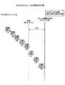
図3は、不急度とリスケジュールとの関係を示す図である。図3中、縦軸に不急度を示し、横軸に作業を示す。不急度がゼロの場合、リスケジュールできない不可作業3aを示す。また、不急度が高い程、リスケジュール可能な作業であり、候補作業3bとして示している。図3の例では、作業C及び作業Gはリスケジュールできない不可タスク3aであり、タスク作業E、作業D、作業F、及び作業Hは、リスケジュール可能な候補作業3bであることを示している。
FIG. 3 is a diagram illustrating the relationship between the degree of urgency and the reschedule. In FIG. 3, the vertical axis indicates the degree of urgency, and the horizontal axis indicates the work. When the degree of urgency is zero, it indicates the impossible work 3a that cannot be rescheduled. Further, the higher the degree of urgency, the more reschedulable work is shown as
図2にて、リスケジュール案作成部52は、不急度の高い作業を対象に、作業のスケジュールを見直して、プロジェクトのリスケジュール案を作成し表示装置15に表示する。図3の例では、作業C及び作業Gはリスケジュールされることなく現状通りのスケジュールとなる。
In FIG. 2, the reschedule
PM2によりリスケジュールが確認され、承認された場合、リスケジュール案作成部52によって作成されたリスケジュール案に従って、DB31内の作業実績情報38が更新される。DB31内の作業実績情報38の更新によって、不急度の高い作業が、プロジェクトの納期後にスケジュールされる。
When the reschedule is confirmed and approved by PM2, the
DB31には、ユーザマスタ32、役割マップ情報33、プロジェクト基本情報34、プロジェクト実績情報35、担当ユーザリンク情報36、作業基本情報37、作業実績情報38等が格納される。各データ例については後述される。
The
また、図2を参照して、プロジェクト管理装置100を利用した全体の流れについて説明する。プロジェクトマネージャPM2が、プロジェクト遅延によるリスケジュール案作成指示を行うと(i)、リスケジュール部50は、不急度判定部51によって、DB31を利用して、指定されたプロジェクトの各作業の不急度を判定する(ii)。
The overall flow using the
不急度判定部51によって各作業の不急度の判定後、リスケジュール案作成部52が、プロジェクトにおいて、不急度に基づいて指定されたプロジェクトの納期後に行える作業を抽出し、システム実施開始後(プロジェクトの納期後)に抽出した作業を行うようにリスケジュール案を作成して表示装置15に表示する(iii)。
After determining the urgency of each work by the
プロジェクトマネージャPM2は、表示されたリスケジュール案を確認して、リスケジュールの確定又はキャンセルを行う(iv)。確定の場合には、DB31にリスケジュール案が反映される。具体的には、後述される作業実績情報38の構成例において、リスケジュール対象となった作業の予定開始日及び予定終了日が変更される。一方、キャンセルの場合、DB31にリスケジュール案の反映は抑止され、リスケジュール対象となった作業の予定開始日及び予定終了日は変更されない。
The project manager PM2 confirms the displayed reschedule plan and confirms or cancels the reschedule (iv). In the case of confirmation, the reschedule plan is reflected in the
図4は、DBの理論構造例を示す図である。図4では、DB30における情報間の関連を示している。図4において、ユーザマスタ32は、役割マップ情報33と関連付けられ、また、役割マップ情報33は、プロジェクト基本情報34と関連付けられる。役割マップ情報33は、プロジェクト毎の担当ユーザと、担当ユーザの役割とを管理する。
FIG. 4 is a diagram illustrating an example of a theoretical structure of a DB. In FIG. 4, the relationship between the information in DB30 is shown. In FIG. 4, the
プロジェクト基本情報34とプロジェクト実績情報35とが関連付けられる。プロジェクト実績情報35は、関連付けられた各プロジェクトの実績情報を管理する。
The project
また、プロジェクト基本情報34と作業基本情報37とが関連付けられる。作業基本情報37は、プロジェクトを構成する1以上の作業が管理され、また、プロジェクト内の作業間の従属関係を管理する。
Further, the project
プロジェクト基本情報34と、作業基本情報37とは、夫々、担当ユーザリンク情報3に関連付けられる。担当ユーザリンク情報36は、ユーザが属する1以上のプロジェクト又は1以上の作業を管理する。
The project
次に、DB31に格納され管理される情報のデータ構成例について図5から図11で説明する。図5は、ユーザマスタのデータ構成例を示す図である。図5において、ユーザマスタ32は、各ユーザの情報を管理するテーブルであり、ユーザID、ユーザタイプ、ユーザ名、パスワード、部署コード、役職、Emailアドレス、電話番号等の項目を有する。
Next, data configuration examples of information stored and managed in the
ユーザIDは、ユーザを一意に識別するIDである。ユーザタイプは、ユーザの場合「0」を示し、グループの場合「1」を示し、仮担当の場合「2」を示す。ユーザ名は、ユーザの名前を示す。 The user ID is an ID that uniquely identifies the user. The user type indicates “0” for a user, “1” for a group, and “2” for a temporary charge. The user name indicates the name of the user.
パスワードは、ユーザのパスワードを示す。部署コードは、ユーザが所属する部署を特定するコードを示す。役職は、部署でのユーザの役職を示す。 The password indicates a user password. The department code indicates a code that identifies the department to which the user belongs. The title indicates the title of the user in the department.
Emailアドレスは、ユーザの電子メールアドレスを示す。電話番号は、ユーザの電話番号を示す。 The Email address indicates the user's email address. The telephone number indicates the user's telephone number.
各項目に設定されるデータ例として、ユーザID「fj******」のユーザタイプは「0」(ユーザ)であり、ユーザ名は「富士 太郎」である。このユーザのパスワードは「abcdefg」であり、部署コード「0a387311a908012c38af41330000****」で特定される部署において、ユーザの役職は「8(担当者)」であることが示されている。また、ユーザのEmailアドレスは「******@**.**.**」であり、電話番号は「XXXX-XXXX」である。 As an example of data set in each item, the user type of the user ID “fj ******” is “0” (user), and the user name is “Taro Fuji”. This user's password is “abcdefg”, indicating that the user's title is “8 (person in charge)” in the department identified by the department code “0a387311a908012c38af41330000 ****”. Further, the user's Email address is “******@**.**.**” and the telephone number is “XXXX-XXXX”.
図6は、役割マップ情報のデータ構成例を示す図である。図6において、役割マップ情報33は、プロジェクトにおいけるユーザの役割を対応付けたテーブルであり、プロジェクト論理ID、仮担当(役割)ユーザID、担当ユーザID、表示順、登録日等の項目を有する。
FIG. 6 is a diagram illustrating a data configuration example of role map information. In FIG. 6,
プロジェクト論理IDは、プロジェクト基本情報34に登録されたプロジェクトを特定するIDを示す。仮担当(役割)ユーザIDは、プロジェクトにおける担当ユーザの役割を識別する情報を示す。担当ユーザIDは、プロジェクトの担当となったユーザのIDを示す。表示順は、プロジェクト内における担当ユーザの表示順を示す。登録日は、プロジェクトに対して担当ユーザを登録した日付を示す。
The project logical ID indicates an ID that identifies a project registered in the project
各項目に設定されるデータ例として、プロジェクト論理ID「0a38743977c3011374da3aee0000****」で特定されるプロジェクトにおいて、仮担当(役割)ユーザIDが「pjmanager」である担当ユーザのIDは「fj******」であり、表示順「9999」で表示され、これら情報の登録日は「2012/9/1」であることが示されている。 As an example of data set for each item, in the project specified by the project logical ID “0a38743977c3011374da3aee0000 ****”, the ID of the user in charge whose temporary user (role) user ID is “pjmanager” is “fj ***” *** "and displayed in the display order" 9999 ", indicating that the registration date of these pieces of information is" 2012/9/1 ".
図7は、プロジェクト基本情報のデータ構成例を示す図である。図7において、プロジェクト基本情報34は、登録されたプロジェクト毎の情報を管理するテーブルであり、プロジェクト論理ID、プロジェクトタイプ、プロジェクト名、作成者のユーザID、新規作成日、最終更新者のユーザID、最終更新日、プロジェクト責任者のユーザID、テンプレートID、表示順等の項目を有する。
FIG. 7 is a diagram illustrating a data configuration example of the project basic information. In FIG. 7, the
プロジェクト論理IDは、プロジェクト基本情報34に登録されたプロジェクトを特定する論理IDを示す。プロジェクトタイプは、運用プロジェクトの場合は「0」を示し、標準フローの場合は「1」を示し、逐次プロジェクトの場合は「2」を示し、ひな型の場合は「3」を示す。プロジェクト名は、プロジェクトのプロジェクト名(タイトル)を示す。
The project logical ID indicates a logical ID that identifies a project registered in the project
作成者のユーザIDは、プロジェクトの基本情報を新規作成したユーザのIDを示す。新規作成日は、プロジェクトを新規に作成した日付を示す。最終更新者のユーザIDは、このプロジェクトの基本情報を最後に更新したユーザのIDを示す。最終更新日は、最後に更新した日付を示す。 The creator's user ID indicates the ID of the user who newly created the basic information of the project. The new creation date indicates the date when a project is newly created. The user ID of the last updater indicates the ID of the user who last updated the basic information of this project. The last update date indicates the date of the last update.
プロジェクト責任者のユーザIDは、プロジェクトマネージャPM2のユーザIDを示す。子作業の数は、プロジェクト配下の作業数を示す。テンプレートIDは、標準WBSに従った雛型プロジェクトのIDを示す。表示順は、プロジェクトの表示順を示す。 The user ID of the project manager indicates the user ID of the project manager PM2. The number of child tasks indicates the number of tasks under the project. The template ID indicates the template project ID according to the standard WBS. The display order indicates the display order of the projects.
各項目に設定されるデータ例として、プロジェクト論理ID「0a38743977c3011374da3aee0000****」で特定されるプロジェクトにおいて、プロジェクトタイプは「0」(運用プロジェクト)であり、プロジェクト名は「××様/△△プロジェクト」である。作成者のユーザIDは「fj******」であり、新規作成日は「2012/12/1」である。最終更新者のユーザIDは「fj******」であり、最終更新日は「2012/2/1」である。また、プロジェクト責任者のユーザIDは「fj******」である。 As an example of data set for each item, in the project specified by the project logical ID “0a38743977c3011374da3aee0000 ****”, the project type is “0” (operation project), and the project name is “XX / △△ Project ". The creator's user ID is “fj ******” and the new creation date is “2012/12/1”. The user ID of the last updater is “fj ******”, and the last update date is “2012/2/1”. The user ID of the project manager is “fj ******”.
子作業の数は「50」個であり、テンプレートIDは「1b49854088d4022384db4veg1213****」であり、表示順は「10」である。 The number of sub-work is “50”, the template ID is “1b49854088d4022384db4veg1213 ****”, and the display order is “10”.
図8は、プロジェクト実績情報のデータ構成例を示す図である。図8において、プロジェクト実績情報35は、各プロジェクトの実績を管理するテーブルであり、プロジェクト論理ID、計画開始日、実績開始日、計画終了日、実績終了日、システム稼働予定日、システム稼働実績日、進捗率、運用ステータス、進捗ステータス等の項目を有する。
FIG. 8 is a diagram illustrating a data configuration example of project performance information. In FIG. 8,
プロジェクト論理IDは、プロジェクト基本情報34に登録されたプロジェクトを特定するIDを示す。
The project logical ID indicates an ID that identifies a project registered in the project
計画開始日は、プロジェクトの計画開始日を示し、実績開始日は、プロジェクトの実際の開始日を示す。計画終了日は、プロジェクトの計画終了日を示し、実績終了日は、プロジェクトの実際の終了日を示す。 The planned start date indicates the planned start date of the project, and the actual start date indicates the actual start date of the project. The planned end date indicates the planned end date of the project, and the actual end date indicates the actual end date of the project.
システム稼働予定日は、顧客での運用開始の予定日を示す。システム稼働実績日は、顧客において実際に運用された日付を示す。進捗率は、プロジェクトの完成度の割合を示す。 The scheduled system operation date indicates the scheduled start date of operation at the customer. The system operation result date indicates a date when the system is actually operated by the customer. The progress rate indicates the percentage of completion of the project.
運用ステータスは、運用中の場合は「0」を示し、準備中の場合は「1」を示し、完了の場合は「9」を示す。進捗ステータスは、完了の場合は「0」を示し、未着手の場合は「1」を示し、予定通りの場合は「2」を示し、やや遅れの場合は「3」を示し、見直し要の場合は「4」を示す。 The operation status indicates “0” when operating, indicates “1” when preparing, and indicates “9” when completed. The progress status indicates “0” when completed, “1” when not yet started, “2” when scheduled, “3” when slightly delayed, and review required In this case, “4” is indicated.
各項目に設定されるデータ例として、プロジェクト論理ID「0a38743977c3011374da3aee0000****」で特定されるプロジェクトに関して、計画開始日は「2012/12/15」であり、実績開始日は「2012/12/20」である。また、計画終了日は「2013/3/1」であり、実績終了日は「2013/3/2」である。そして、このプロジェクトの顧客におけるシステム稼働予定日は「2013/2/25」であり、システム稼働実績日は「2013/2/26」である。 As an example of data set for each item, for the project specified by the project logical ID “0a38743977c3011374da3aee0000 ****”, the planned start date is “2012/12/15” and the actual start date is “2012/12 / 20 ”. The planned end date is “2013/3/1” and the actual end date is “2013/3/2”. The planned system operation date for this project customer is “2013/2/25”, and the system operation performance date is “2013/2/26”.
進捗率は「100」%であり、運用ステータスは「9」(完了)を示し、このプロジェクトは完了していることを示す。また、進捗ステータスにおいても「0」(完了)を示している。 The progress rate is “100”%, the operation status indicates “9” (completed), and this project is completed. The progress status also indicates “0” (completed).
図9は、担当ユーザリンク情報のデータ構成例を示す図である。図9において、担当ユーザリンク情報36は、担当ユーザ毎にプロジェクト又は作業との関連を管理するテーブルであり、ユーザID、リンク元の論理ID、関連オブジェクトのタイプ、プロジェクト論理ID、役割、表示順等の項目を有する。
FIG. 9 is a diagram illustrating a data configuration example of responsible user link information. In FIG. 9, the responsible user link
ユーザIDは、プロジェクト又は作業のいずれかを担当する担当ユーザのIDを示す。リンク元の論理IDは、プロジェクト基本情報34に登録されているプロジェクト論理ID又は作業基本情報37に登録されている作業論理IDを示す。
The user ID indicates the ID of a responsible user who is in charge of either the project or the work. The link source logical ID indicates a project logical ID registered in the project
関連オブジェクトのタイプは、関連付けられたオブジェクトがプロジェクト又は作業のいずれかであることを示す。プロジェクト論理IDは、リンク元が作業の場合にプロジェクト論理IDが示される。 The related object type indicates that the associated object is either a project or a work. The project logical ID indicates the project logical ID when the link source is work.
役割は、担当するプロジェクト又は作業におけるユーザの役割を示す。オブジェクトタイプがプロジェクトを示す場合において、修正不可は「0」で示され、修正可は「2」で示される。オブジェクトタイプが作業を示す場合において、写し(予約)は「0」で示され、主担当は「1」で示され、レビュアは「2」で示され、依頼者は「3」で示される。表示順は、このユーザの担当ユーザリンク情報の表示順を示す。 The role indicates the role of the user in the project or work in charge. When the object type indicates a project, “uncorrectable” is indicated by “0”, and “correctable” is indicated by “2”. When the object type indicates work, the copy (reservation) is indicated by “0”, the main charge is indicated by “1”, the reviewer is indicated by “2”, and the requester is indicated by “3”. The display order indicates the display order of the user link information for this user.
各項目に設定されるデータ例として、ユーザID「fj******」に関連するリンク元の論理IDは「0a387439d9870105e215ed2e0000****」であり、関連オブジェクトのタイプは「2」(作業)であり、プロジェクト論理IDはリンク元が作業の場合に示され、この例では、「0a38743977c3011374da3aee0000****」である。また、役割は「2」であるため、ユーザID「fj******」で特定されるユーザは、この作業のレビュアであることが示されている。 As an example of data set for each item, the logical ID of the link source related to the user ID “fj ******” is “0a387439d9870105e215ed2e0000 ****”, and the type of the related object is “2” (work The project logical ID is indicated when the link source is work, and in this example is “0a38743977c3011374da3aee0000 ****”. Since the role is “2”, it is indicated that the user specified by the user ID “fj ******” is a reviewer of this work.
図10は、作業基本情報のデータ構成例を示す図である。図10において、作業基本情報37は、登録された作業毎の情報を管理するテーブルであり、作業論理ID、作業名、表示順、プロジェクト論理ID、親作業論理ID、階層レベル、子作業の数、作業の一意キー、リードタイム(標準期間(日))、最終更新者、最終更新日等の項目を有する。
FIG. 10 is a diagram illustrating a data configuration example of the basic work information. In FIG. 10, work
作業論理IDは、作業基本情報37に登録された作業を特定する論理IDを示す。作業名は、作業の名称(タイトル)を示す。表示順は、作業の表示順を示す。プロジェクト論理IDは、作業のプロジェクト論理IDを示し、関連付けられる。親作業論理IDは、作業の親作業論理IDを示し、関連付けられる。
The work logical ID indicates a logical ID that identifies a work registered in the work
階層レベルは、プロジェクトにおいて、作業が位置する階層レベルを示す。子作業の数は、作業配下にある子作業の数を示す。作業の一意キーは、作業に一意に与えられたキーを示す。異なる作業論理IDであっても作業の一意キーが同一の場合、作業として同じであることを示す。リードタイムは、作業を完成させるために必要な日数を示す。 The hierarchy level indicates the hierarchy level where the work is located in the project. The number of child tasks indicates the number of child tasks under the task. The work unique key indicates a key uniquely assigned to the work. Even if the work logical IDs are different, if the work unique key is the same, it indicates that the work is the same. The lead time indicates the number of days required to complete the work.
最終更新者は、この作業の基本情報を更新したユーザのIDを示す。最終更新日は、この作業の基本情報を更新した最終日を示す。 The last updater indicates the ID of the user who updated the basic information of this work. The last update date indicates the last date when the basic information of this work is updated.
図11は、作業実績情報のデータ構成例を示す図である。図11において、作業実績情報38は、作業毎の実績を管理するテーブルであり、作業論理ID、進捗状況(%)、ステータス、実績期間(日数)、実績工数(時間)、予定開始日、実績開始日、予定終了日、実績終了日、リスケジュール有無等の項目を有する。
FIG. 11 is a diagram illustrating a data configuration example of work performance information. In FIG. 11, work result
作業論理IDは、作業基本情報37に登録された作業を特定する論理IDを示す。進捗状況(%)は、作業の進捗度を示す。ステータスは、現在の作業の状態を示し、予定の状態では「0」を示し、着手可の状態では「1」を示し、着手中の状態では「2」を示し、承認中の状態では「3」を示し、差戻しの状態では「4」を示し、完了の状態では「9」を示す。
The work logical ID indicates a logical ID that identifies a work registered in the work
実績期間(日数)は、実際の作業日数を示す。実績工数(時間)は、実際の工数を時間で示す。予定開始日は、作業の予定開始日を示す。実績開始日は、実際に作業を開始した日付を示す。予定終了日は、作業の予定終了日を示す。実績終了日は、実際に作業を終了した日付を示す。リスケジュール有無は、リスケジュールされたか否かを示すフラグであり、リスケジュール無しの場合は「0」を示し、リスケジュール有りの場合は「1」を示す。 The actual period (number of days) indicates the actual number of work days. The actual man-hour (time) indicates the actual man-hour in time. The scheduled start date indicates the scheduled start date of the work. The actual start date indicates the date when the work was actually started. The scheduled end date indicates the scheduled end date of the work. The actual end date indicates the date when the work is actually ended. The rescheduled presence / absence is a flag indicating whether rescheduling has been performed, and indicates “0” when there is no rescheduling, and indicates “1” when there is rescheduling.
各項目に設定されるデータ例として、作業論理ID「0a387439d9870105e215ed2e0000****」で特定される作業の進捗状況は「100」%であり、ステータスは「9」(完了)を示す。実績期間(日数)は「1」日であり、実績工数(時間)は「2」時間である。 As an example of data set in each item, the progress status of the work specified by the work logic ID “0a387439d9870105e215ed2e0000 ****” is “100”%, and the status indicates “9” (completed). The actual period (days) is “1” days, and the actual man-hours (hours) is “2” hours.
予定開始日「2013/1/21」に対して、実績開始日は「2013/1/22」であったことを示し、予定終了日「2013/1/21」に対して、実績終了日は「2013/1/22」であったことを示す。 For the scheduled start date “2013/1/21”, the actual start date was “2013/1/22”. For the planned end date “2013/1/21”, the actual end date was Shows that it was “2013/1/22”.
リスケジュール前の、DB31に基づくプロジェクトのマスタスケジュールの例を図12で説明する。図12は、マスタスケジュールの例を示す図である。図12に例示されるマスタスケジュールでは、作業Aから作業Hまでの作業がシステム稼働予定日までにスケジュールされた状態が示されている。図12中、作業Aから作業Hの作業名の下の( )内に完了又は未完了を示しているが、各作業A〜Hの完了又は未完了の区別は、文字色等により視認し易い表示で示してもよい。また、各作業名の「−>」印は、作業の予定開始日又は実績開始日から予定終了日又は実績終了日までの長さを表し、「−>」印の下にリードタイムを示す日数を示している。
An example of a master schedule of a project based on the
マスタスケジュールを表示装置15に表示した時点(本日(2012/12/21))、即ち、システム稼働予定日(2012/12/30)の10日前の時点において、作業A及び作業Bは完了しているが、作業Cから作業Hまでは未完了である。未完了の作業のうち、本日(2012/12/21)の時点までに作業C、作業D及び作業Eは完了を予定していた作業である。 At the time when the master schedule is displayed on the display device 15 (today (2012/12/21)), that is, 10 days before the scheduled system operation date (2012/12/30), work A and work B are completed. However, operations C to H are incomplete. Among the incomplete work, the work C, the work D, and the work E are the work that was scheduled to be completed by the time of today (2012/12/21).
本実施の形態に係るプロジェクト管理装置100は、リスケジュール部50によって、未完了の作業Cから作業Hのうち、不急度に基づいて1以上の作業をシステム稼働予定日(2012/12/30)にリスケジュールする。以下、作業Aから作業Hを有するプロジェクトをプロジェクト名「プロジェクトα」で特定するものとする。
In the
不急度を判定してリスケジュールするリスケジュール部50によるリスケジュール処理を図13から図16で説明する。
The rescheduling process by the rescheduling
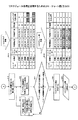
図13から図16は、リスケジュール処理を説明するためのフローチャート図である。図13において、スケジュール部40は、マスタスケジュール表示部44によって、プロジェクトマネージャPM2によるマスタスケジュールの表示要求に応じて、要求で指定されるプロジェクトのマスタスケジュールを表示装置15に表示させる(ステップS11)。
13 to 16 are flowcharts for explaining the rescheduling process. In FIG. 13, the
マスタスケジュール表示部44は、マスタスケジュールの表示要求で指定されるプロジェクト名とシステム稼働予定日と示す対象プロジェクト情報61を記憶部130に記憶する。システム稼働予定日は、マスタスケジュールの表示要求で指定されるプロジェクト名のプロジェクト基本情報34のプロジェクト論理IDで関連付けられるプロジェクト実績情報35から取得することができる。
The master
また、マスタスケジュール表示部44は、プロジェクト論理IDで関連付けられる作業基本情報37から作業名、リードタイムを取得し、また、作業実績情報38から各作業の予定開始日、予定終了日、ステータスを取得して、対象作業情報62を記憶部130に記憶する。対象プロジェクト情報61と対象作業情報62とに基づいて、図12に示すマスタスケジュールが表示装置15に表示される。
The master
そして、マスタスケジュールの表示後、プロジェクトマネージャPM2が、プロジェクトの遅延を確認すると、プロジェクト遅延によりリスケジュール案作成指示を行う。リスケジュール案作成指示は、表示されたマスタスケジュールの画面に構成されるリスケジュールボタンを押下することによって行われる。 After displaying the master schedule, when the project manager PM2 confirms the delay of the project, the project manager PM2 issues a reschedule plan creation instruction due to the project delay. The reschedule plan creation instruction is issued by pressing a reschedule button configured on the displayed master schedule screen.
マスタスケジュール表示部44は、表示されたマスタスケジュールの画面に構成されるリスケジュールボタンの押下を検出したか否かを判断する(ステップS12)。リスケジュールボタンの押下ではない場合(ステップS12がNo)、このリスケジュールに係る処理を終了する。リスケジュールボタンの押下を検出した場合(ステップS12がYes)、リスケジュール部50が起動する(ステップS13)。
The master
図14において、リスケジュール部50は、対象作業情報62によって示される全ての作業を対象とし(ステップS14)、対象作業情報62から順にレコードを処理対象として、対象作業のステータスが未完了を示すか否かを判断する(ステップS15)。対象作業のステータスが未完了を示す場合(ステップS15がYes)、未完了の作業について、不急度判定部51による不急度判定処理を行う(ステップS16)。
In FIG. 14, the rescheduling
各作業の不急度判定は、下記の式によって計算される。作業Cを例として示すが、他の各作業について同様に不急度を計算する。 The urgency determination of each work is calculated by the following formula. Although the work C is shown as an example, the urgency is similarly calculated for each of the other works.
作業Cの不急度
=(
(PM(1)の作業Cのリスケ率(%))×(PM(1)の熟練度)
+ ・・・
+ (PM(n)の作業Cのリスケ率(%))×(PM(n)の熟練度)
)÷n 式(1)
ここで、PM(1)からPM(n)は異なるプロジェクトマネージャPM2を示し、nは過去に作業Cをシステム稼動後にリスケジュールしたことのあるプロジェクトマネージャの総人数を示す。
Urgency of work C
= (
(Risk rate of work C in PM (1) (%)) x (PM (1) skill level)
+ ...
+ (Risk rate of work C of PM (n) (%)) × (PM (n) skill level)
) ÷ n Formula (1)
Here, PM (1) to PM (n) indicate different project managers PM2, and n indicates the total number of project managers who have rescheduled work C after the system is operated in the past.
上記式(1)において、各プロジェクトマネージャPM(i)(i=1、2、・・・、n)の作業Cのリスケ率(リスケジュール率)(%)は、
作業Cのリスケ率(%)
= (PM(i)が作業Cをリスケジュールしたプロジェクト数)
÷ (PM(i)がリスケジュールを実施したプロジェクト数)
× 100 式(2)
によって計算される。
In the above formula (1), the risk rate (reschedule rate) (%) of the work C of each project manager PM (i) (i = 1, 2,..., N) is
Risk rate for work C (%)
= (Number of projects where PM (i) rescheduled work C)
÷ (Number of projects for which PM (i) has been rescheduled)
× 100 Formula (2)
Is calculated by
PM(i)のユーザIDを含むプロジェクト基本情報34からプロジェクト論理IDで関連付けられるプロジェクト実績情報35の数が、各PM(i)が担当したプロジェクト数に相当する。プロジェクト実績情報35毎に、プロジェクト論理IDで関連付けられる作業基本情報37の作業論理IDを示す作業実績情報38を取得し、取得した作業実績情報38でリスケジュール有無の値が「1」(リスケジュール有)を示す場合に、そのプロジェクトにおいてリスケジュールが実施されたと判断する。リスケジュールを実施したと判断したプロジェクト数をカウントする。PM(i)がリスケジュールを実施したプロジェクト数を得ることができる。
The number of
上述したようにPM(i)のユーザID及びプロジェクト論理IDに基づいて得られたプロジェクト実績情報35の、プロジェクト論理IDで関連付けられる作業基本情報37のうち、作業名が所定の作業(例えば、作業C)と一致する作業基本情報37に関して、更に、作業論理IDで関連付けられる作業実績情報38のリスケジュール有無の値「1」である場合に、そのプロジェクトにおいて所定の作業(作業C)をリスケジュールしたと判断する。よって、所定の作業(例えば、作業C)をリスケジュールしたプロジェクト数を取得することができる。
As described above, among the work
リスケ率は、PM(i)がリスケジュールを実施したプロジェクト数に対する所定の作業(作業C)をリスケジュールしたプロジェクト数の割合で示される。 The risk rate is indicated by the ratio of the number of projects in which a predetermined work (work C) is rescheduled to the number of projects in which PM (i) has been rescheduled.
また、上記式(1)において、各プロジェクトマネージャPM(i)の熟練度は、
PM(i)の熟練度
= (PM(i)の過去の成功プロジェクト数)
÷ (PM(i)の過去の担当プロジェクト数) 式(3)
によって計算される。ここで、成功プロジェクト数とは、稼働日に遅延がなかったプロジェクト数を示す。
In the above formula (1), the proficiency level of each project manager PM (i) is
Proficiency level of PM (i)
= (The number of past successful projects of PM (i))
÷ (Number of past projects in charge of PM (i)) Formula (3)
Is calculated by Here, the number of successful projects indicates the number of projects that were not delayed on the operating day.
上述したようにPM(i)のユーザID及びプロジェクト論理IDに基づいて得られたプロジェクト実績情報35のうち、進捗ステータスの値が「0」(完了)を示すプロジェクト実績情報35の数が、PM(i)の過去の担当プロジェクト数に相当する。
As described above, among the
上述の進捗ステータスの値が「0」(完了)を示すプロジェクト実績情報35のうち、システム稼働実績日がシステム稼働予定日と一致又はシステム稼働予定日より前の日付を示すプロジェクト実績情報35の数が、PM(i)の過去の成功プロジェクト数に相当する。
Of the
PM(i)の熟練度は、PM(i)の過去の担当プロジェクト数に対するPM(i)の過去の成功プロジェクト数の割合で示される。 The skill level of PM (i) is indicated by the ratio of the number of successful projects in the past of PM (i) to the number of projects in charge of the past of PM (i).
対象作業のステータスが完了を示す場合(ステップS15がNo)、プロジェクトの全ての作業のチェックを完了したか否かを判断する(ステップS17)。全ての作業のチェックを完了していない場合(ステップS17がNo)、リスケジュール部50は、対象作業情報62の次のレコードを処理対象として、ステップS15へ戻り上述同様の処理を繰り返す。全ての作業のチェックを完了している場合(ステップS17がYes)、未完了を示す作業の不急度一覧表63がリスケジュール処理における内部データ60として記憶部130に保存される(ステップS18)。
When the status of the target work indicates completion (No in step S15), it is determined whether or not all the works in the project have been checked (step S17). If the check of all work has not been completed (No at Step S17), the rescheduling
不急度一覧表63は、レコードNo、作業名、リードタイム(日)、予定開始日、予定終了日、不急度、リスケフラグ等の項目を有する。
The
レコードNoは、不急度一覧表63の各レコードを識別する番号である。作業名は、作業基本情報37に登録された作業名を示す。リードタイムは、作業に必要な日数を示す。予定開始日は、作業の予定開始日を示す。予定終了日は、作業の予定終了日を示す。
The record No. is a number for identifying each record in the
不急度は、不急度判定部51によって計算された作業の不急度を示す。リスケフラグは、リスケジュール処理においてリスケジュールされない場合に未リスケジュールを示す「0」が設定され、リスケジュール処理においてリスケジュールされた場合にリスケジュール済みを示す「9」が設定される。不急度一覧表63の作成時には、リスケフラグは、全ての作業で「0」を示す。
The urgency indicates the urgency of the work calculated by the
図15にて、リスケジュール部50のリスケジュール案作成部52は、システム稼働日までの残日数を求める(ステップS19)。リスケジュール案作成部52は、プロジェクト実績情報35を参照して、リスケジュール対象のプロジェクトのシステム稼働予定日を取得する。また、リスケジュール案作成部52は、現在の日付を取得して、システム稼働予定日と現在の日付との差分を計算する。
In FIG. 15, the rescheduling
そして、リスケジュール案作成部52は、システム稼働前の作業のリードタイム総和を求める(ステップS20)。リスケジュール案作成部52は、不急度一覧表63のリスケフラグが「0」のレコードのリードタイムを全て足して、リードタイム総和を計算する。
Then, the reschedule
リスケジュール案作成部52は、ステップS19で算出した「システム稼働予定日までの残日数」がステップS20で算出した「システム稼働前の作業のリードタイム総和」以上であるか否かを判断する(ステップS21)。
The reschedule
「システム稼働予定日までの残日数」が「システム稼働前の作業のリードタイム総和」より少ない場合(ステップS21のNo)、リスケジュール案作成部52は、不急度一覧表63の中でリスケフラグが「0」かつ不急度が最も高い値のレコードのリスケフラグを「9」に変更する(ステップS21−2)。
When the “number of remaining days until the scheduled system operation date” is smaller than the “total lead time of the work before the system operation” (No in step S21), the rescheduling
そして、リスケジュール案作成部52は、ステップS20へ戻り、上述した同様の処理を繰り返す。ステップS21の判断条件が満たされた状態を、不急度一覧表63−2で示す。図14に示す不急度一覧表63は、図15の不急度一覧表63−2に更新される。
Then, the reschedule
不急度一覧表63−2では、ステップS20、S21、及びS21−2の処理の繰り返しによって、作業Fと作業Hのレコードのリスケフラグが「9」に設定されたことを示している。 The urgency list 63-2 indicates that the risk flag of the records of work F and work H is set to “9” by repeating the processes of steps S20, S21, and S21-2.
「システム稼働予定日までの残日数」が「システム稼働前の作業のリードタイム総和」以上である場合(ステップS21のYes)、リスケジュール案作成部52は、リスケジュール案を作成する(ステップS22)。リスケジュール案作成部52は、リスケフラグが更新された不急度一覧表63−2において、リスケフラグが「9」のレコードについて、システム稼働予定日「2012/12/30」の後に予定開始日及び予定終了日を順に設定する。
When the “number of remaining days until the scheduled system operation date” is equal to or greater than the “total lead time of work before system operation” (Yes in step S21), the reschedule
図14に示す不急度一覧表63−2のうち、リスケジュール案作成部52は、作業Fの予定開始日「2012/12/21」及び予定終了日「2012/12/24」が、「2012/12/31」及び「2012/1/3」に変更する。また、作業Fの予定開始日「2012/12/28」及び予定終了日「2012/12/30」が、「2013/1/4」及び「2013/1/6」に変更する。図15の不急度一覧表63−2が、図15の不急度一覧表63−4に更新される。
In the urgency list 63-2 illustrated in FIG. 14, the reschedule
リスケジュール案作成部52は、不急度一覧表63−4に基づいてリスケジュール案を表示装置15に表示する(ステップS23)。後述される図17に示すようなリスケジュール案が表示装置15に表示される。
The reschedule
このように、残された作業期間に対応して、不急度の高い作業から自動的にシステム稼働後の工程にスケジュールし直す。納期までの作業期間と残り作業のリードタイムの総和とを比較して、納期までの作業期間が短い場合、不急度の高い作業から順番にシステム稼働後の工程にリスケジュールする。 In this way, in accordance with the remaining work period, the work with a high degree of urgency is automatically rescheduled to the process after the system operation. When the work period up to the delivery date and the total lead time of the remaining work are compared, and the work period up to the delivery date is short, the work schedules are rescheduled in the order of higher urgency in order.
プロジェクトマネージャPM2は、表示されたリスケジュール案を確認して、問題ないと判断した場合、リスケジュール案をDB31に反映させるために、画面に用意されている「OK」ボタンを押下する。一方、プロジェクトマネージャPM2は、リスケジュール案を承認できない場合は、画面に用意されている「キャンセル」ボタンを押下する。
If the project manager PM2 confirms the displayed reschedule plan and determines that there is no problem, the project manager PM2 presses an “OK” button prepared on the screen in order to reflect the reschedule plan in the
図16にて、リスケジュール案作成部52は、リスケジュール案を表示した画面において、「OK」ボタンの押下を検出したか否かを判断する(ステップS24)。「キャンセル」ボタンの押下を検出した場合(ステップS24のNo)、リスケジュール案作成部52は、リスケジュール案を破棄して(ステップS25)、このリスケジュール処理を終了する。リスケジュール案作成部52は、DB31に反映されずに不急度一覧表63−4が破棄される。DB31から得られる不急度は、不急度一覧表63の状態を維持する。
In FIG. 16, the reschedule
一方、「OK」ボタンの押下を検出した場合(ステップS24のYes)、リスケジュール案作成部52は、リスケジュール案をDB31に反映して(ステップS26)このリスケジュール処理を終了する。リスケジュール案作成部52は、不急度一覧表63−4を用いて、DB31を反映する。具体的には、不急度一覧表63−4のリスケフラグが「9」を示す作業F及び作業Hの予定開始日及び予定終了日で、作業実績情報38の予定開始日及び予定終了日を更新する。
On the other hand, when the pressing of the “OK” button is detected (Yes in step S24), the reschedule
不急度一覧表63−4に基づいて作成されたリスケジュール案を図17に示す。図17は、リスケジュール案を示す図である。図17に示すリスケジュール案において、未完了の作業Cから作業Hのうち、作業Fと作業Hとがシステム稼働予定日「2012/12/30」の後にスケジュールされる案が示されている。 FIG. 17 shows a reschedule plan created based on the urgency list 63-4. FIG. 17 is a diagram showing a reschedule plan. The reschedule plan shown in FIG. 17 shows a plan in which work F and work H among unfinished works C to H are scheduled after the scheduled system operation date “2012/12/30”.
プロジェクトマネージャPM2は、表示装置15に表示されたリスケジュール案を確認して、リスケジュール案を適用するか否かを判断することができる。
The project manager PM2 can confirm the reschedule plan displayed on the
上述したように、リスケジュール案は、作業の不急度に基づいて自動的に行われる。また、不急度の計算では、過去のプロジェクトマネージャのリスケジュール率及び熟練度が考慮されることにより精度よく不急度を算出することができる。従って、リスケジュール案では、現在のプロジェクトマネージャPM2のプロジェクトの経験に寄らず、精度よくシステム稼働予定日後にリスケジュール可能な作業を抽出でき、また、適切にリスケジュールすることができる。 As described above, the reschedule plan is automatically performed based on the urgency of the work. In the calculation of the urgency level, the urgency level can be calculated with high accuracy by taking into account the reschedule rate and skill level of the past project manager. Therefore, in the rescheduling plan, work that can be rescheduled after the planned system operation date can be extracted accurately and rescheduled appropriately, regardless of the current project manager PM2 project experience.
また、不急度の計算では、累積された過去のプロジェクトマネージャのリスケジュール率及び熟練度が考慮されるため、同じ作業であっても、累積された情報に応じてリスケジュールの仕方が変動する。例えば、リスケジュールする時期が異なると提示されるリスケジュール案が異なる。 In addition, in the calculation of urgency, the reschedule rate and skill level of the past project managers accumulated are taken into consideration, so even if the work is the same, the rescheduling method varies depending on the accumulated information. . For example, rescheduling proposals to be presented differ depending on the time of rescheduling.
過去のプロジェクトマネージャのリスケジュール率及び熟練度の累積された情報に応じてリスケジュール案が変動する例について、図18及び図19で説明する。図18及び図19では、同じプロジェクトαを現在(「2012/12/21」)と一年後(「2013/12/21」)とでリスケジュールを行った場合の例を示す。 An example in which the reschedule plan varies according to the accumulated information of the reschedule rate and skill level of past project managers will be described with reference to FIGS. 18 and 19 show an example in which the same project α is rescheduled between the present (“2012/12/21”) and one year later (“2013/12/21”).
図18は、現在の不急度一覧表を示す図である。図18に示す不急度一覧表63−2において、作業Cの不急度は「0」であり、作業Dの不急度は「60」であり、作業Eの不急度は「30」であり、作業Fの不急度は「70」であり、作業Gの不急度は「30」であり、作業Hの不急度は「90」である。 FIG. 18 is a diagram showing a current urgency list. In the urgency list 63-2 illustrated in FIG. 18, the urgency of the work C is “0”, the urgency of the work D is “60”, and the urgency of the work E is “30”. The urgency of work F is “70”, the urgency of work G is “30”, and the urgency of work H is “90”.
不急度一覧表63−2のリスケフラグが「9」を示す作業F及び作業Hがリスケジュールされる。 Work F and work H in which the risk flag of the urgency list 63-2 indicates “9” are rescheduled.
作業Fの予定開始日「2012/12/21」及び予定終了日「2012/12/24」がリスケジュールされて、不急度一覧表63−4に示すように、予定開始日「2012/12/21」及び予定終了日「2012/12/28」となる。 The scheduled start date “2012/12/21” and scheduled end date “2012/12/24” of the work F are rescheduled, and as shown in the urgency list 63-4, the scheduled start date “2012/12 / 21 ”and scheduled end date“ 2012/12/28 ”.
作業Hの予定開始日「2012/12/28」及び予定終了日「2012/12/30」がリスケジュールされて、不急度一覧表63−4に示すように、予定開始日「2012/12/31」及び予定終了日「2013/1/3」となる。 The scheduled start date “2012/12/28” and scheduled end date “2012/12/30” of the work H are rescheduled, and as shown in the urgency list 63-4, the scheduled start date “2012/12 / 31 "and scheduled end date" 2013/1/3 ".
プロジェクトにおいては、標準の運用契約の内容が変更されることで作業Gがシステム稼働日以降に実施しても大きな問題にならなくなる場合、一年後には作業Gが多くのプロジェクトでリスケジュールされた実績が積みあがり、不急度が高くなる可能性ある。一方で、作業Gがリスケジュールされる分、他の作業がリスケジュールされないようになり、相対的に他の作業の不急度が低くなる可能性がある。 In the project, if the contents of the standard operation contract are changed and work G does not become a big problem even if it is implemented after the system operation date, work G was rescheduled in many projects one year later There is a possibility that the results will be accumulated and the urgency may be high. On the other hand, as work G is rescheduled, other work is not rescheduled, and the urgency of other work may be relatively lowered.
図19は、1年後の不急度一覧表を示す図である。図19に示す不急度一覧表63−6において、作業Cの不急度は「0」であり、作業Dの不急度は「40」であり、作業Eの不急度は「15」であり、作業Fの不急度は「70」であり、作業Gの不急度は「75」であり、作業Hの不急度は「65」である。 FIG. 19 is a diagram showing a list of urgency after one year. In the urgency list 63-6 shown in FIG. 19, the urgency of the work C is “0”, the urgency of the work D is “40”, and the urgency of the work E is “15”. The urgency of work F is “70”, the urgency of work G is “75”, and the urgency of work H is “65”.
図19に示す不急度一覧表63−6では、図18の不急度一覧表63−2と比べて、作業D、作業E、及び作業Hの不急度が低下している。1年後では、作業Gの不急度が「30」であったのが「75」と高く変化している。 In the urgency list 63-6 shown in FIG. 19, the urgency of the work D, the work E, and the work H is lower than that of the urgency list 63-2 in FIG. One year later, the urgency level of the work G was “30”, which is highly changed to “75”.
一方で、作業Dの不急度は「60」から「40」と低く変化し、作業Eの不急度は「30」から「15」と低く変化し、作業Hの不急度は「90」から「65」と低く変化している。 On the other hand, the urgency of the work D changes from “60” to “40”, the urgency of the work E changes from “30” to “15”, and the urgency of the work H changes to “90”. ”To“ 65 ”.
この場合、不急度一覧表63−6のリスケフラグが「9」を示す作業F及び作業Gがリスケジュールされる。 In this case, work F and work G in which the risk flag of the urgency list 63-6 indicates “9” are rescheduled.
作業Fの予定開始日「2013/12/21」及び予定終了日「2013/12/24」がリスケジュールされて、不急度一覧表63−8に示すように、予定開始日「2013/12/31」及び予定終了日「2014/1/3」となる。 The scheduled start date “2013/12/21” and the scheduled end date “2013/12/24” of the work F are rescheduled, and as shown in the urgency list 63-8, the scheduled start date “2013/12/2013” / 31 "and scheduled end date" 2014/1/3 ".
作業Gの予定開始日「2013/12/25」及び予定終了日「2013/12/27」がリスケジュールされて、不急度一覧表63−4に示すように、予定開始日「2014/1/4」及び予定終了日「2014/1/6」となる。 The scheduled start date “2013/12/25” and the scheduled end date “2013/12/27” of the work G are rescheduled. As shown in the urgency list 63-4, the scheduled start date “2014/1 / 4 ”and scheduled end date“ 2014/1/6 ”.
このように、不急度が過去の実績に基づいて計算されることにより、精度良く判断されるため、より安全なリスケジュール案を作成することができる。 As described above, since the degree of urgency is calculated based on the past results, it is determined with high accuracy, so that a safer reschedule plan can be created.
上述したように、本実施の形態では、経験の少ないPMでも最適なスケジュール修正が可能となる。プロジェクトの遅延や失敗を防ぎ、確実なシステム稼働を支援することに加えて、PMの作業負荷軽減に寄与する。 As described above, in the present embodiment, it is possible to correct the schedule optimally even with a PM with little experience. In addition to preventing project delays and failures and supporting reliable system operation, it contributes to reducing PM workload.
本発明は、具体的に開示された実施例に限定されるものではなく、特許請求の範囲から逸脱することなく、種々の変形や変更が可能である。 The present invention is not limited to the specifically disclosed embodiments, and various modifications and changes can be made without departing from the scope of the claims.
以上の実施例を含む実施形態に関し、更に以下の付記を開示する。
(付記1)
コンピュータによって実行される複数の作業を有するプロジェクトのリスケジュール方法であって、
前記作業毎の実績を示す作業実績情報を記憶した記憶部を参照して、指定されたプロジェクトに係る該作業実績情報に基づいて未完了の作業を抽出し、
前記抽出された未完了の作業毎に、前記プロジェクトの納期後に作業可能な程度を示す不急度を算出し、
前記未完了の作業毎に前記不急度を対応付けた不急度一覧表を作成して記憶部に記憶し、
前記不急度一覧表に基づいて、前記未完了の作業を前記納期後にリスケジュールしたリスケジュール案を作成し、
前記リスケジュール案を表示装置に表示させる
ことを特徴とするリスケジュール方法。
(付記2)
前記不急度は、過去に前記作業をリスケジュールしたプロジェクトマネージャに対して、リスケジュールした割合と該プロジェクトマネージャの熟練度とを積和した値を、プロジェクトマネージャの総数で割った値であることを特徴とする付記1記載のリスケジュール方法。
(付記3)
前記未完了の作業毎のリスケジュールした割合は、前記プロジェクトマネージャがリスケジュールを実施したプロジェクト数に対する該プロジェクトマネージャが該作業をリスケジュールしたプロジェクト数の割合であることを特徴とする付記2記載のリスケジュール方法。
(付記4)
前記プロジェクトマネージャの熟練度は、該プロジェクトマネージャの過去の担当プロジェクト数に対する該プロジェクトマネージャの稼働日に遅延がなかった成功プロジェクトの割合であることを特徴とする付記2又は3記載のリスケジュール方法。
(付記5)
前記未完了の作業の前記不急度の値が高い程、リスケジュールの候補作業であることを示し、値がゼロの場合は、リスケジュールができない不可作業であることを示すことを特徴とする付記2乃至4のいずれか一項記載のリスケジュール方法。
(付記6)
プロジェクトの作業毎の実績を示す作業実績情報を記憶した記憶部を参照して、指定されたプロジェクトに係る該作業実績情報に基づいて未完了の作業を抽出し、
前記抽出された未完了の作業毎に、前記プロジェクトの納期後にリスケジュール可能な程度を示す不急度を算出し、
前記未完了の作業毎に前記不急度を対応付けた不急度一覧表を作成して記憶部に記憶し、
前記不急度一覧表に基づいて、前記未完了の作業を前記納期後にリスケジュールしたリスケジュール案を作成し、
前記リスケジュール案を表示装置に表示させる
処理をコンピュータに実行させるプロジェクトのリスケジュールプログラム。
(付記7)
プロジェクトの作業毎の実績を示す作業実績情報を記憶した記憶部と、
前記記憶部に記憶された前記作業実績情報をから未完了の作業を抽出し、該抽出された未完了の作業毎に、前記プロジェクトの納期後にリスケジュール可能な程度を示す不急度を算出して、該未完了の作業毎に前記不急度を対応付けた不急度一覧表を作成して記憶部に記憶する不急度判定部と、
前記記憶部に記憶された前記不急度一覧表に基づいて、リスケジュール可能な未完了の作業を、前記納期後にリスケジュールしたリスケジュール案を作成して、該リスケジュール案を表示装置に表示させるリスケジュール案作成部と
を有するプロジェクトのリスケジュール装置。
The following additional notes are further disclosed with respect to the embodiment including the above examples.
(Appendix 1)
A method for rescheduling a project having a plurality of operations performed by a computer comprising:
With reference to the storage unit that stores work performance information indicating the performance of each work, the unfinished work is extracted based on the work performance information related to the designated project,
For each of the extracted unfinished tasks, calculate the urgency indicating the degree of work that can be performed after the delivery date of the project,
Create an urgency list in which the urgency is associated with each incomplete work and store it in a storage unit;
Based on the urgency list, create a reschedule plan that reschedules the incomplete work after the delivery date;
A rescheduling method comprising displaying the reschedule plan on a display device.
(Appendix 2)
The urgency is a value obtained by multiplying the project manager who rescheduled the work in the past by the product sum of the rescheduled ratio and the skill level of the project manager divided by the total number of project managers. The rescheduling method according to
(Appendix 3)
The re-scheduled ratio for each incomplete work is a ratio of the number of projects that the project manager reschedules to the number of projects that the project manager has rescheduled. Rescheduling method.
(Appendix 4)
4. The rescheduling method according to
(Appendix 5)
The higher the value of the inadequacy of the unfinished work, the more rescheduling candidate work is indicated, and when the value is zero, it indicates that the work cannot be rescheduled. The rescheduling method according to any one of
(Appendix 6)
With reference to the storage unit storing work performance information indicating the performance of each work of the project, the unfinished work is extracted based on the work performance information related to the designated project,
For each of the extracted unfinished operations, calculate the urgency indicating the degree of rescheduling after the delivery date of the project,
Create an urgency list in which the urgency is associated with each incomplete work and store it in a storage unit;
Based on the urgency list, create a reschedule plan that reschedules the incomplete work after the delivery date;
A project reschedule program for causing a computer to execute a process of displaying the reschedule plan on a display device.
(Appendix 7)
A storage unit that stores work performance information indicating the performance of each project work;
An uncompleted work is extracted from the work performance information stored in the storage unit, and for each of the extracted uncompleted work, an urgent degree indicating a reschedulable degree after the delivery date of the project is calculated. An urgent degree determination unit that creates an urgent degree list in which the urgent degree is associated with each incomplete work and stores the urgent degree list in a storage unit;
Based on the list of urgency stored in the storage unit, a reschedule plan for rescheduling unfinished work that can be rescheduled after the delivery date is created, and the reschedule plan is displayed on the display device A rescheduling device for a project having a rescheduling plan creation unit.
11 CPU
12 主記憶装置
13 補助記憶装置
14 入力装置
15 表示装置
17 通信I/F
18 ドライブ
19 記憶媒体
31 DB
32 ユーザマスタ
33 役割マップ情報
34 プロジェクト基本情報
35 プロジェクト実績情報
36 担当ユーザリンク情報
37 作業基本情報
38 作業実績情報
40 スケジュール部
41 マスタスケジュール作成部
42 担当者割り当て部
43 実績管理部
44 マスタスケジュール表示部
50 リスケジュール部
51 不急度判定部
52 リスケジュール案作成部
100 プロジェクト管理装置
PM2 プロジェクトマネージャ
11 CPU
12
18
32
Claims (4)
前記作業毎の実績を示す作業実績情報を記憶した記憶部を参照して、指定されたプロジェクトに係る該作業実績情報に基づいて未完了の作業を抽出し、
前記抽出された未完了の作業毎に、過去に該作業をリスケジュールしたプロジェクトマネージャに対して、リスケジュールした割合と該プロジェクトマネージャの熟練度とを積和した値を、プロジェクトマネージャの総数で割ることによって、前記プロジェクトの納期後に作業可能な程度を示す不急度を算出し、
前記未完了の作業毎に前記不急度を対応付けた不急度一覧表を作成して記憶部に記憶し、
前記不急度一覧表に基づいて、前記未完了の作業を前記納期後にリスケジュールしたリスケジュール案を作成し、
前記リスケジュール案を表示装置に表示させる
ことを特徴とするリスケジュール方法。 A method for rescheduling a project having a plurality of operations performed by a computer comprising:
With reference to the storage unit that stores work performance information indicating the performance of each work, the unfinished work is extracted based on the work performance information related to the designated project,
For each extracted uncompleted task, the value obtained by multiplying the sum of the rescheduled ratio and the skill level of the project manager by the total number of project managers is divided for the project manager who rescheduled the task in the past. it allows to calculate the non-urgent degree indicating a degree workable after delivery of the project,
Create an urgency list in which the urgency is associated with each incomplete work and store it in a storage unit;
Based on the urgency list, create a reschedule plan that reschedules the incomplete work after the delivery date;
A rescheduling method comprising displaying the reschedule plan on a display device.
前記抽出された未完了の作業毎に、過去に該作業をリスケジュールしたプロジェクトマネージャに対して、リスケジュールした割合と該プロジェクトマネージャの熟練度とを積和した値を、プロジェクトマネージャの総数で割ることによって、前記プロジェクトの納期後に作業可能な程度を示す不急度を算出し、
前記未完了の作業毎に前記不急度を対応付けた不急度一覧表を作成して記憶部に記憶し、
前記不急度一覧表に基づいて、前記未完了の作業を前記納期後にリスケジュールしたリスケジュール案を作成し、
前記リスケジュール案を表示装置に表示させる
処理をコンピュータに実行させるプロジェクトのリスケジュールプログラム。 With reference to the storage unit storing work performance information indicating the performance of each work of the project, the unfinished work is extracted based on the work performance information related to the designated project,
For each extracted uncompleted task, the value obtained by multiplying the sum of the rescheduled ratio and the skill level of the project manager by the total number of project managers is divided for the project manager who rescheduled the task in the past. it allows to calculate the non-urgent degree indicating a degree workable after delivery of the project,
Create an urgency list in which the urgency is associated with each incomplete work and store it in a storage unit;
Based on the urgency list, create a reschedule plan that reschedules the incomplete work after the delivery date;
A project reschedule program for causing a computer to execute a process of displaying the reschedule plan on a display device.
Priority Applications (1)
| Application Number | Priority Date | Filing Date | Title |
|---|---|---|---|
| JP2013138771A JP6201459B2 (en) | 2013-07-02 | 2013-07-02 | Project rescheduling method and program |
Applications Claiming Priority (1)
| Application Number | Priority Date | Filing Date | Title |
|---|---|---|---|
| JP2013138771A JP6201459B2 (en) | 2013-07-02 | 2013-07-02 | Project rescheduling method and program |
Publications (2)
| Publication Number | Publication Date |
|---|---|
| JP2015011650A JP2015011650A (en) | 2015-01-19 |
| JP6201459B2 true JP6201459B2 (en) | 2017-09-27 |
Family
ID=52304719
Family Applications (1)
| Application Number | Title | Priority Date | Filing Date |
|---|---|---|---|
| JP2013138771A Expired - Fee Related JP6201459B2 (en) | 2013-07-02 | 2013-07-02 | Project rescheduling method and program |
Country Status (1)
| Country | Link |
|---|---|
| JP (1) | JP6201459B2 (en) |
Families Citing this family (2)
| Publication number | Priority date | Publication date | Assignee | Title |
|---|---|---|---|---|
| JP6266562B2 (en) * | 2015-05-13 | 2018-01-24 | 日本電信電話株式会社 | Support device, control method of support device, and program |
| JP7026410B2 (en) * | 2020-06-12 | 2022-02-28 | 株式会社ジュリア | Information management system, server and user terminal |
Family Cites Families (3)
| Publication number | Priority date | Publication date | Assignee | Title |
|---|---|---|---|---|
| JP2001250047A (en) * | 2000-03-06 | 2001-09-14 | Sanyo Electric Co Ltd | System and method for supplementing commodity |
| JP2004070540A (en) * | 2002-08-05 | 2004-03-04 | Hitachi Ltd | Checking scheduling method and device |
| JP2013045308A (en) * | 2011-08-24 | 2013-03-04 | Mitsubishi Heavy Ind Ltd | Construction progress management support system and method |
-
2013
- 2013-07-02 JP JP2013138771A patent/JP6201459B2/en not_active Expired - Fee Related
Also Published As
| Publication number | Publication date |
|---|---|
| JP2015011650A (en) | 2015-01-19 |
Similar Documents
| Publication | Publication Date | Title |
|---|---|---|
| JP5697624B2 (en) | Project management support system and project management support program | |
| US11210075B2 (en) | Software automation deployment and performance tracking | |
| WO2005071564A1 (en) | A project management method and system | |
| JP2008517385A (en) | System and method for process automation and implementation | |
| JP5196991B2 (en) | Manufacturing process management apparatus, manufacturing process management method, and computer program | |
| KR20180109785A (en) | Method and apparatus for assisting strategy map management based on schedule-assessment item and todo-assessment item | |
| JP6201459B2 (en) | Project rescheduling method and program | |
| US20100205225A1 (en) | Method and Apparatus for Transforming a Process | |
| KR20180013474A (en) | Method and apparatus for assisting strategy map management based on schedule-assessment item and todo-assessment item | |
| JP2019091213A (en) | Work management device, work management system, and conference room reservation system | |
| JP2009276904A (en) | Project management device, project management method, project management program and recording medium | |
| JP6131725B2 (en) | Information processing apparatus and information processing program | |
| JP2006146530A (en) | Scheduling support system | |
| JP2005025495A (en) | Design change automation system | |
| JP5854745B2 (en) | DATA INTERFACE DEVICE, DATA INTERFACE METHOD, DATA INTERFACE PROGRAM, AND PROCESS MANAGEMENT SYSTEM FOR PROCESS MANAGEMENT TOOL | |
| JP2002123657A (en) | System and method for managing work | |
| JP7550712B2 (en) | Planned start and end date calculation device, planned start and end date calculation method, and planned start and end date calculation program | |
| JP4696050B2 (en) | Work result management apparatus, work plan support apparatus, and storage medium storing a program for causing a computer to perform processing in these apparatuses | |
| JP2024064839A (en) | Business management program, apparatus, and method | |
| JP7078268B2 (en) | Worker selection equipment, systems, methods, and programs | |
| JP2024095887A (en) | Maintenance work planning system and maintenance work planning method | |
| JP2006163514A (en) | Personnel selection support system and program applied thereto | |
| JP2010271815A (en) | Work management device, program, and work management method | |
| JP7304139B2 (en) | PROJECT SUPPORT SYSTEM, PROJECT SUPPORT DEVICE AND PROJECT SUPPORT METHOD | |
| US20210295274A1 (en) | Workflow management device, workflow management system, method of managing workflow, and non-transitory recording medium |
Legal Events
| Date | Code | Title | Description |
|---|---|---|---|
| A621 | Written request for application examination |
Free format text: JAPANESE INTERMEDIATE CODE: A621 Effective date: 20160405 |
|
| A977 | Report on retrieval |
Free format text: JAPANESE INTERMEDIATE CODE: A971007 Effective date: 20170217 |
|
| A131 | Notification of reasons for refusal |
Free format text: JAPANESE INTERMEDIATE CODE: A131 Effective date: 20170228 |
|
| A521 | Request for written amendment filed |
Free format text: JAPANESE INTERMEDIATE CODE: A523 Effective date: 20170425 |
|
| TRDD | Decision of grant or rejection written | ||
| A01 | Written decision to grant a patent or to grant a registration (utility model) |
Free format text: JAPANESE INTERMEDIATE CODE: A01 Effective date: 20170801 |
|
| A61 | First payment of annual fees (during grant procedure) |
Free format text: JAPANESE INTERMEDIATE CODE: A61 Effective date: 20170814 |
|
| R150 | Certificate of patent or registration of utility model |
Ref document number: 6201459 Country of ref document: JP Free format text: JAPANESE INTERMEDIATE CODE: R150 |
|
| LAPS | Cancellation because of no payment of annual fees |