JP6201397B2 - Photo sticker creation apparatus and method, and program - Google Patents
Photo sticker creation apparatus and method, and program Download PDFInfo
- Publication number
- JP6201397B2 JP6201397B2 JP2013088837A JP2013088837A JP6201397B2 JP 6201397 B2 JP6201397 B2 JP 6201397B2 JP 2013088837 A JP2013088837 A JP 2013088837A JP 2013088837 A JP2013088837 A JP 2013088837A JP 6201397 B2 JP6201397 B2 JP 6201397B2
- Authority
- JP
- Japan
- Prior art keywords
- image
- user
- period
- extracted
- subject
- Prior art date
- Legal status (The legal status is an assumption and is not a legal conclusion. Google has not performed a legal analysis and makes no representation as to the accuracy of the status listed.)
- Expired - Fee Related
Links
Images


Description
本技術は、写真シール作成装置および方法、並びにプログラムに関し、特に、利用者が意図する構図の画像を提供できるようにする写真シール作成装置および方法、並びにプログラムに関する。 The present technology relates to a photographic sticker creating apparatus and method, and a program, and more particularly, to a photographic sticker creating apparatus and method and a program capable of providing an image having a composition intended by a user.
利用者を撮影し、撮影画像に対して利用者に編集を行わせ、編集後の画像をシール紙に印刷して提供する写真シール機が知られている。このような写真シール機は娯楽(遊戯)施設等に設置される。 There is known a photo sticker that takes a picture of a user, causes the user to edit the shot image, and prints and provides the edited image on sticker paper. Such a photo sticker is installed in an entertainment facility.
写真シール機によって提供される1ゲームの流れは、通常、撮影空間内にいる利用者を被写体として撮影し、利用者を編集空間に移動させ、編集空間内で行われる操作に従って画像を編集し、編集後の画像である編集済み画像をシール紙に印刷して排出するという流れになる。 The flow of one game provided by the photo-seal machine usually shoots a user in the shooting space as a subject, moves the user to the editing space, edits the image according to operations performed in the editing space, The edited image, which is the edited image, is printed on a sticker sheet and discharged.
写真シール機での撮影においては、カメラの撮影範囲の背景全体に幕(背景カーテン)が配置されており、被写体である利用者とともに背景カーテンが撮影されるため、背景の色が均一化される。 When shooting with a photo sticker machine, a curtain (background curtain) is placed over the entire background of the shooting range of the camera, and the background curtain is shot with the user who is the subject, so the background color is uniform. .
しかしながら、近年、写真シール機では、ユーザの趣向に合わせて、どんなポーズ(例えば、大の字ポーズなどの全身ポーズ)にでも対応できるように、カメラの撮像範囲の領域を広げるようになった。これにより、撮影された画像の背景の一部にしか背景カーテンが写らないことがある。 However, in recent years, in the photo sticker, the range of the imaging range of the camera has been expanded so as to be able to cope with any pose (for example, a whole body pose such as a large character pose) according to the user's preference. As a result, the background curtain may appear only in part of the background of the photographed image.
そこで、例えば、背景カーテンからはみ出した部分も背景カーテンと同様の画像となるように処理される写真シール機も提案されている(例えば、特許文献1参照)。 In view of this, for example, a photographic seal machine has been proposed in which a portion protruding from the background curtain is processed so as to have the same image as the background curtain (see, for example, Patent Document 1).
また、撮影時に被写体を撮影した画像の構図として、被写体である利用者の立ち位置などがベストポジションである否かを判定し、ベストポジションになった場合にアナウンスすることで、構図のよい画像を得るようにした写真シール機も提案されている(例えば、特許文献2参照)。 In addition, as a composition of the image of the subject taken at the time of shooting, it is determined whether or not the standing position of the user who is the subject is the best position, and an announcement is made when the best position is reached. There has also been proposed a photographic seal machine (see, for example, Patent Document 2).
しかしながら、例えば、特許文献1のような写真シール機では、利用者にとって不要とされる部分までが背景画像とされることになるので、利用者が意図する構図の画像を提供できないことがあった。
However, for example, in a photo sticker as in
また、特許文献2のような写真シール機では、利用者が移動してベストポジションを探す必要があるため、面倒であり、時間がかかることがあった。加えて、ベストポジションを探すことができなかった場合は、利用者が意図する構図の画像を提供できず、利用者の満足度を高めることができなかった。
In addition, the photo sticker as in
さらに、利用者は撮影空間内のタッチパネルモニタに表示された画像を見ながら、誘導情報に従って撮影空間内を移動するが、一般的な利用者は小顔に写りたいため、カメラに近づくことをためらう傾向がある。 Furthermore, the user moves in the shooting space according to the guidance information while viewing the image displayed on the touch panel monitor in the shooting space, but a general user hesitates to approach the camera because he wants to appear in a small face. Tend.
つまり、利用者には写真に写った自分の顔をできるだけ小さく見せたいという願望があり、例えば、「もっと前に来てね!」などの誘導情報を提示しても、なかなかカメラに近づこうとしない利用者も多い。 In other words, there is a desire for users to make their faces appear as small as possible in the photograph. For example, even if guidance information such as “Come ahead” is presented, it is difficult to approach the camera. There are many users.
このため、従来の技術では、画像の中で利用者の顔が十分な大きさで表示されず、利用者が意図する構図の画像を提供できないことがあった。 For this reason, in the conventional technology, the user's face is not displayed in a sufficiently large size in the image, and an image having a composition intended by the user may not be provided.
本発明は、このような状況に鑑みてなされたものであり、利用者が意図する構図の画像を提供できるようにするものである。 The present invention has been made in view of such a situation, and makes it possible to provide an image having a composition intended by a user.
本発明の一側面は、利用者を被写体とした画像を取得し、前記取得した画像に対して編集情報を入力する編集入力作業を行わせ、さらに、得られた編集済みの前記利用者の画像を前記利用者に提供する写真シール作成装置において、撮影空間内で前記被写体を含んだ所定の範囲の画像を撮影する撮影手段と、前記撮影手段により撮影された画像である原画像から、前記被写体を含む一部の領域を抽出して表示するように制御する画像表示制御手段と、前記撮影空間内における前記利用者の理想的な位置に係る情報を前記利用者に提示する位置情報提示手段とを備え、前記撮影手段により静止画像が撮影されるまでの期間を、前記撮影手段が動画像の撮影を開始した後の所定の時間に対応する第1の期間と、前記撮影手段により前記静止画像が撮影される前の所定の時間に対応し、前記第1の期間よりも後に設定されている第2の期間に分類し、前記画像表示制御手段は、前記第1の期間において、原画像から抽出される領域を第1の面積の領域として抽出し、前記第2の期間において、原画像から抽出される領域を第2の面積の領域として抽出し、前記第1の期間において原画像から抽出される画像に占める前記被写体の面積の割合が、前記第2の期間において原画像から抽出される画像に占める前記被写体の面積の割合より小さい写真シール作成装置である。 One aspect of the present invention is to acquire an image of a user as a subject, to perform editing input work for inputting editing information to the acquired image, and to obtain the edited image of the user In the photo sticker creating apparatus that provides the user with the above, from the photographing means for photographing an image of a predetermined range including the subject in the photographing space, and from the original image that is the image photographed by the photographing means, the subject Image display control means for controlling to extract and display a part of the area including the information, and position information presentation means for presenting the user with information related to the ideal position of the user in the imaging space; A period until a still image is shot by the shooting unit, a first period corresponding to a predetermined time after the shooting unit starts shooting a moving image, and the still image by the shooting unit But Corresponding to a predetermined time before being shaded, it is classified into a second period set after the first period, and the image display control means extracts from the original image in the first period A region extracted from the original image in the second period, and a region extracted from the original image in the second period, and extracted from the original image in the first period. The photographic sticker creating apparatus is configured such that the ratio of the area of the subject in the image is smaller than the ratio of the area of the subject in the image extracted from the original image in the second period .
前記利用者により、第1の撮影コースが選択されて前記撮影手段による撮影が行われる場合、前記画像表示制御手段は、前記第1の期間において、原画像から抽出される領域を第1の面積の領域として抽出し、前記第2の期間において、原画像から抽出される領域を、前記第1の面積として抽出された領域の中に含まれ、前記第1の面積より小さい第2の面積の領域として抽出し、前記利用者により、第2の撮影コースが選択されて前記撮影手段による撮影が行われる場合、前記画像表示制御手段は、前記第2の期間において、前記第1の面積と同じ大きさの第2の面積の領域を前記原画像から抽出するようにすることができる。 When the user selects the first shooting course and performs shooting by the shooting unit, the image display control unit sets the area extracted from the original image as the first area in the first period. The region extracted from the original image in the second period is included in the region extracted as the first area and has a second area smaller than the first area. When the second shooting course is selected by the user and shooting is performed by the shooting unit, the image display control unit is the same as the first area in the second period. A region having a second area having a size can be extracted from the original image.
前記第1の撮影コースは、前記利用者の顔または上半身をアップにした画像を撮影する撮影コースであり、前記第2の撮影コースは、前記利用者の全身の画像を撮影する撮影コースであるようにすることができる。 The first shooting course is a shooting course for shooting an image with the user's face or upper body up, and the second shooting course is a shooting course for shooting an image of the whole body of the user. Can be.
本発明の一側面は、利用者を被写体とした画像を取得し、前記取得した画像に対して編集情報を入力する編集入力作業を行わせ、さらに、得られた編集済みの前記利用者の画像を前記利用者に提供する写真シール作成装置の写真シール作成方法において、撮影手段が、撮影空間内で前記被写体を含んだ所定の範囲の画像を撮影し、画像表示制御手段が、前記撮影された画像である原画像から、前記被写体を含む一部の領域を抽出して表示し、位置情報提示手段が、前記撮影空間内における前記利用者の理想的な位置に係る情報を前記利用者に提示するように制御するステップを含み、前記撮影手段により静止画像が撮影されるまでの期間を、前記撮影手段が動画像の撮影を開始した後の所定の時間に対応する第1の期間と、前記撮影手段により前記静止画像が撮影される前の所定の時間に対応し、前記第1の期間よりも後に設定されている第2の期間に分類し、前記画像表示制御手段は、前記第1の期間において、原画像から抽出される領域を第1の面積の領域として抽出し、前記第2の期間において、原画像から抽出される領域を第2の面積の領域として抽出し、前記第1の期間において原画像から抽出される画像に占める前記被写体の面積の割合が、前記第2の期間において原画像から抽出される画像に占める前記被写体の面積の割合より小さくなるように抽出する写真シール作成方法である。 One aspect of the present invention is to acquire an image of a user as a subject, to perform editing input work for inputting editing information to the acquired image, and to obtain the edited image of the user In the photo sticker creation method of the photo sticker creation device that provides the user with a photograph sticker, the photographing means picks up an image of a predetermined range including the subject in the photographing space, and the image display control means captures the photograph. A part of the area including the subject is extracted and displayed from the original image as an image, and the position information presenting means presents the user with information on the ideal position of the user in the shooting space. A period until a still image is shot by the shooting unit, a first period corresponding to a predetermined time after the shooting unit starts shooting a moving image, and By shooting means Corresponding to a predetermined time before the still image is shot, the image display control means classifies the second period set after the first period, and the image display control means A region extracted from the original image is extracted as a region having a first area, a region extracted from the original image is extracted as a region having a second area in the second period, and the original region is extracted in the first period. In the photo sticker creation method, the ratio of the area of the subject in the image extracted from the image is smaller than the ratio of the area of the subject in the image extracted from the original image in the second period. .
本発明の一側面は、利用者を被写体とした画像を取得し、前記取得した画像に対して編集情報を入力する編集入力作業を行わせ、さらに、得られた編集済みの前記利用者の画像を前記利用者に提供する写真シール作成装置における処理をコンピュータに実行させるプログラムであって、撮影手段が、撮影空間内で前記被写体を含んだ所定の範囲の画像を撮影し、画像表示制御手段が、前記撮影された画像である原画像から、前記被写体を含む一部の領域を抽出して表示するように制御し、位置情報提示手段が、前記撮影空間内における前記利用者の理想的な位置に係る情報を前記利用者に提示するように制御するステップを含む処理をコンピュータに実行させ、前記撮影手段により静止画像が撮影されるまでの期間を、前記撮影手段が動画像の撮影を開始した後の所定の時間に対応する第1の期間と、前記撮影手段により前記静止画像が撮影される前の所定の時間に対応し、前記第1の期間よりも後に設定されている第2の期間に分類し、前記画像表示制御手段は、前記第1の期間において、原画像から抽出される領域を第1の面積の領域として抽出し、前記第2の期間において、原画像から抽出される領域を第2の面積の領域として抽出し、前記第1の期間において原画像から抽出される画像に占める前記被写体の面積の割合が、前記第2の期間において原画像から抽出される画像に占める前記被写体の面積の割合より小さくなるように抽出するプログラムである。 One aspect of the present invention is to acquire an image of a user as a subject, to perform editing input work for inputting editing information to the acquired image, and to obtain the edited image of the user Is a program for causing a computer to execute processing in the photo sticker creating apparatus that provides the user with a photographing means, photographing an image of a predetermined range including the subject in a photographing space, and an image display control means , Controlling to extract and display a part of the area including the subject from the original image that is the captured image, and the position information presenting means is the ideal position of the user in the imaging space to execute the process including the step of controlling so as to present information relating to the user on the computer, the period until the still image is captured by the imaging means, the imaging means is the moving picture Corresponding to a first period corresponding to a predetermined time after the start of photographing and a predetermined time before the still image is photographed by the photographing means, it is set after the first period. In the second period, the image display control means extracts the area extracted from the original image as the area of the first area in the first period, and from the original image in the second period. The extracted area is extracted as a second area area, and the ratio of the area of the subject in the image extracted from the original image in the first period is extracted from the original image in the second period. This is a program for extracting the image so as to be smaller than the proportion of the area of the subject in the image .
本発明の一側面においては、撮影空間内で被写体を含んだ所定の範囲の画像が撮影され、前記撮影された画像である原画像から、前記被写体を含む一部の領域が抽出されて表示され、前記撮影空間内における利用者の理想的な位置に係る情報が前記利用者に提示され、静止画像が撮影されるまでの期間が、動画像の撮影を開始した後の所定の時間に対応する第1の期間と、静止画像が撮影される前の所定の時間に対応し、前記第1の期間よりも後に設定されている第2の期間に分類され、前記第1の期間において、原画像から抽出される領域が第1の面積の領域として抽出され、前記第2の期間において、原画像から抽出される領域が第2の面積の領域として抽出され、前記第1の期間において原画像から抽出される画像に占める前記被写体の面積の割合が、前記第2の期間において原画像から抽出される画像に占める前記被写体の面積の割合より小さくなるように抽出される。 In one aspect of the present invention, an image of a predetermined range including a subject is photographed in a photographing space, and a partial region including the subject is extracted and displayed from the original image that is the photographed image. The period from when the user is presented with information regarding the ideal position of the user in the shooting space until the still image is shot corresponds to a predetermined time after the start of moving image shooting. The first period corresponds to a predetermined time before the still image is captured, and is classified into a second period set after the first period. In the first period, the original image Is extracted as a first area, and in the second period, a region extracted from the original image is extracted as a second area, and is extracted from the original image in the first period. The subject in the extracted image The ratio of the area is extracted to be smaller than the ratio of the area of the object occupying the image extracted from the original image in the second period.
本発明によれば、利用者に負担をかけることなく、利用者が意図する構図の画像を提供できる。 According to the present invention, an image having a composition intended by a user can be provided without imposing a burden on the user.
以下、本発明を適用した具体的な実施の形態について、図面を参照しながら詳細に説明する。 Hereinafter, specific embodiments to which the present invention is applied will be described in detail with reference to the drawings.
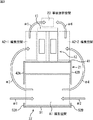
図1は、画像生成装置としての写真シール作成装置1の外観の構成例を示す斜視図である。
FIG. 1 is a perspective view showing a configuration example of the appearance of a photo
写真シール作成装置1は、撮影や編集等の作業を利用者にゲームとして行わせ、撮影画像や編集済み画像を提供する代わりに利用者より代金を受け取るゲーム機である。写真シール作成装置1はゲームセンタなどの店舗に設置される。利用者は1人であることもあるし、複数人であることもある。
The photo
写真シール作成装置1が提供するゲームで遊ぶ利用者は、代金を投入し、自身が被写体となって撮影を行い、撮影によって得られた撮影画像の中から選択した編集対象の画像に対して、背景や前景の画像となる合成用画像や手書きの線画やスタンプ画像を合成する編集機能を用いて編集を行うことにより、撮影画像を彩り豊かな画像にする。利用者は、編集済みの画像が印刷されたシール紙を受け取って一連のゲームを終了させることになる。
A user who plays in the game provided by the photo
図1に示すように、写真シール作成装置1は、主に、撮影ユニット11、編集部12、および事後接客部13から構成される。撮影ユニット11と編集部12が接した状態で設置され、編集部12と事後接客部13が接した状態で設置される。
As shown in FIG. 1, the photo
撮影ユニット11は、撮影部21と背景部22から構成される。撮影部21と背景部22は所定の距離だけ離れて設置され、撮影部21と背景部22の間に形成される空間である撮影空間において撮影処理が行われる。
The photographing unit 11 includes a photographing
撮影部21は撮影処理を利用者に行わせる装置である。撮影部21は、撮影空間に入り、撮影処理を行っている利用者の正面に位置する。撮影空間を正面に臨む面を構成する撮影部21の正面パネル41には、撮影処理時に利用者により用いられるタッチパネルモニタなどが設けられる。撮影空間にいる利用者から見て左側の面を左側面、右側の面を右側面とすると、撮影部21の左側面が側面パネル42Aにより構成され、右側面が側面パネル42Bにより構成される。
The photographing
背景部22は、正面を向いて撮影処理を行っている利用者の背面側に位置する板状の部材である背面パネル51、背面パネル51の左端に取り付けられ、側面パネル42Aより横幅の狭い板状の部材である側面パネル52A、および、背面パネル51の右端に取り付けられ、側面パネル42Bより横幅の狭い板状の部材である側面パネル52B(図示せず)から構成される。
The
撮影部21の左側面を構成する側面パネル42Aと背景部22の側面パネル52Aは、ほぼ同一平面に設けられ、それぞれの上部が板状の部材である連結部23Aによって連結される。また、撮影部21の右側面を構成する側面パネル42Bと背景部22の側面パネル52Bは、ほぼ同一平面に設けられ、それぞれの上部が板状の部材である連結部23Bによって連結される。
The
撮影部21の側面パネル42A、連結部23A、および背景部22の側面パネル52Aに囲まれることによって形成される開口が撮影空間の出入り口G1となる。図示されないが、撮影部21の側面パネル42B、連結部23B、および背景部22の側面パネル52Bに囲まれることによって形成される開口も撮影空間の出入り口G2となる。
An opening formed by being surrounded by the side panel 42 </ b> A of the photographing
背景部22の上部には、背面パネル51、側面パネル52A、および側面パネル52Bに支持される形で背景カーテンユニット25が設けられる。背景カーテンユニット25には、色または柄の異なる、背景に利用される巻き取り式の背景カーテンが複数収納される。背景カーテンユニット25は、撮影部21に設けられたカメラ等による撮影と連動して動作し、撮影の際に、例えば利用者により選択された色のカーテンを下ろし、その他のカーテンを巻き取る。
The
なお、背景カーテンユニット25に収納される背景カーテンとしては、複数枚のカーテンを1枚のクロマキ用のカーテンとして使用する昇降式カーテンを用意してもよい。また、クロマキ用のカーテンを予め撮影空間の背面となる背面パネル51に張り付けるとともに、合成用の背景画像を複数種類用意し、撮影処理や編集処理において、利用者が所望する背景画像をカーテンの部分に合成することができるようにしてもよい。
In addition, as a background curtain accommodated in the
撮影空間の上方には、撮影部21の正面パネル41、連結部23A、連結部23B、および背景カーテンユニット25に囲まれる開口が形成され、その開口の一部を覆うように天井ストロボユニット24が設けられる。天井ストロボユニット24の一端が連結部23Aに固定され、他端が連結部23Bに固定される。天井ストロボユニット24は、撮影に合わせて撮影空間内に向けて発光するストロボを内蔵する。天井ストロボユニット24を構成するストロボの内部には蛍光灯が設けられており、撮影空間の照明としても機能する。
An opening surrounded by the
編集部12は、撮影処理によって得られた画像を編集する処理である編集処理を利用者に行わせる装置である。編集部12は、一方の側面が撮影部21の正面パネル41の背面に接するように撮影ユニット11に連結して設けられる。編集部12には、編集処理時に利用者により用いられるタブレット内蔵モニタなどの構成が設けられる。
The
図1に示す編集部12の構成を正面側の構成とすると、2組の利用者が同時に編集処理を行うことができるように、編集部12の正面側と背面側には編集処理に用いられる構成がそれぞれ設けられる。
If the configuration of the
編集部12の正面側は、床面に対して垂直な面であり、側面パネル42Aとほぼ平行な面である面71と、面71の上方に形成された斜面72から構成され、編集処理に用いられる構成が斜面72に設けられる。斜面72の左側には、柱状の形状を有し、照明装置74の一端を支持する支持部73Aが設けられる。支持部73Aの上面にはカーテンレール26を支持する支持部75が設けられる。斜面72の右側にも、照明装置74の他端を支持する支持部73B(図2)が設けられる。
The front side of the
編集部12の上方にはカーテンレール26が取り付けられる。カーテンレール26は、上から見たときの形状がコの字状となるように3本のレール26A乃至26Cを組み合わせて構成される。平行に設けられるレール26Aと26Bの一端は、連結部23Aと連結部23Bにそれぞれ固定され、他端に残りの一本のレール26Cの両端が接合される。
A
カーテンレール26には、編集部12の正面前方の空間と背面前方の空間の内部が外から見えないようにカーテンが取り付けられる。カーテンレール26に取り付けられたカーテンにより囲まれる編集部12の正面前方の空間と背面前方の空間が、利用者が編集処理を行う編集空間となる。
A curtain is attached to the
図2は、写真シール作成装置1を別の角度から見た斜視図である。
FIG. 2 is a perspective view of the photo
事後接客部13は事後接客処理を利用者に行わせる装置である。事後接客処理には、撮影画像や編集済みの画像を携帯電話機などの携帯端末に送信する処理、ミニゲームを利用者に行わせる処理、アンケートに答えさせる処理などが含まれる。
The subsequent
図2に示すように、事後接客部13は、所定の厚さを有する板状の筐体をその一部として有しており、残りの部分は編集部12の左側面と一体に設けられる。事後接客部13の正面には、事後接客処理時に利用者により用いられるタブレット内蔵モニタや、撮影画像や編集済みの画像が印刷されたシール紙が排出される排出口などが設けられる。事後接客部13の正面前方の空間が、シール紙への印刷が終わるのを待っている利用者が事後接客処理を行う事後接客空間となる。
As shown in FIG. 2, the
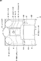
ここで、写真シール作成ゲームの流れと、それに伴う利用者の移動について図3を参照して説明する。図3は、写真シール作成装置1を上から見た平面図である。
Here, the flow of the photo sticker creation game and the accompanying movement of the user will be described with reference to FIG. FIG. 3 is a plan view of the photo
写真シール作成装置1の利用者は、白抜き矢印#1で示すように出入り口G1から、または白抜き矢印#2で示すように出入り口G2から、撮影部21と背景部22の間に形成された撮影空間A1に入り、撮影部21に設けられたカメラやタッチパネルモニタなど利用して撮影処理を行う。
The user of the photo
撮影処理を終えた利用者は、白抜き矢印#3で示すように出入り口G1を使って撮影空間A1から出て編集空間A2−1に移動するか、白抜き矢印#4で示すように出入り口G2を使って撮影空間A1から出て編集空間A2−2に移動する。
The user who has finished the shooting process exits the shooting space A1 and moves to the editing space A2-1 using the doorway G1 as indicated by the
編集空間A2−1は、編集部12の正面側の編集空間であり、編集空間A2−2は、編集部12の背面側の編集空間である。編集空間A2−1と編集空間A2−2のいずれの空間に移動するのかが、撮影部21のタッチパネルモニタの画面表示などによって案内される。例えば2つの編集空間のうちの空いている方の空間が移動先として案内される。編集空間A2−1または編集空間A2−2に移動した利用者は編集処理を開始する。編集空間A2−1の利用者と、編集空間A2−2の利用者は同時に編集処理を行うことができる。
The editing space A2-1 is an editing space on the front side of the
編集処理が終了した後、撮影画像や編集済みの画像の中から選択された画像の印刷が開始される。画像の印刷中、編集処理を終えた利用者は、編集空間A2−1で編集処理を行っていた場合には白抜き矢印#5で示すように編集空間A2−1から事後接客空間A3に移動して事後接客処理を行う。また、編集処理を終えた利用者は、編集空間A2−2で編集処理を行っていた場合には白抜き矢印#6で示すように編集空間A2−2から事後接客空間A3に移動し、事後接客空間A3において事後接客処理を行う。
After the editing process is finished, printing of an image selected from the photographed image and the edited image is started. During printing of the image, the user who has finished the editing process moves from the editing space A2-1 to the subsequent customer service space A3 as indicated by the
画像の印刷が終了したとき、利用者は、事後接客部13に設けられた排出口からシール紙を受け取り、一連の写真シール作成ゲームを終えることになる。
When the printing of the image is finished, the user receives the sticker paper from the outlet provided in the
次に、各装置の構成について説明する。 Next, the configuration of each device will be described.
[撮影部の構成]
図4は、撮影部21の正面の構成例を示す図である。撮影部21は、正面パネル41、側面パネル42A、および側面パネル42Bが、箱状の形状を有するベース部43に取り付けられることによって構成される。
[Configuration of shooting section]
FIG. 4 is a diagram illustrating a configuration example of the front of the photographing
正面パネル41は撮影空間A1で撮影処理を行う利用者の正面に位置し、側面パネル42Aと側面パネル42Bは、それぞれ、撮影空間A1で撮影処理を行う利用者の左側、右側に位置する。
The
正面パネル41のほぼ中央には撮影・表示ユニット81が設けられる。撮影・表示ユニット81は、カメラ91、正面ストロボ92、およびタッチパネルモニタ93から構成される。
An imaging / display unit 81 is provided in the approximate center of the
カメラ91は、CCD(Charge Coupled Device)などの撮像素子により構成され、撮影空間A1にいる利用者を撮影する。カメラ91により取り込まれた動画像は、タッチパネルモニタ93にリアルタイムで表示される。利用者により撮影が指示されたときなどの所定のタイミングでカメラ91により取り込まれた画像は撮影画像(静止画像)として保存される。
The
カメラ91を囲むように発光面が設けられた正面ストロボ92は、他のストロボと同様にカメラ91による撮影に合わせて発光し、被写体としての利用者の顔付近を正面から照射する。
The front strobe 92 provided with a light emitting surface so as to surround the
カメラ91の下側に設けられたタッチパネルモニタ93は、LCD(Liquid Crystal Display)などのモニタと、それに積層されたタッチパネルにより構成される。タッチパネルモニタ93は、カメラ91により取り込まれた動画像を表示するライブビューモニタとしての機能と、各種のGUI(Graphical User Interface)画像を表示し、利用者の選択操作をタッチパネルにより受け付ける機能とを備えている。タッチパネルモニタ93には、適宜、撮影結果としての静止画像や、背景等の画像が合成された後の動画像が表示される。
The touch panel monitor 93 provided on the lower side of the
正面パネル41には、撮影・表示ユニット81の位置を基準として、上方に上ストロボ82が設置される。また、左方に左ストロボ83が設置され、右方に右ストロボ84が設置される。
On the
上ストロボ82は、利用者を上前方から照射する。左ストロボ83は、利用者を左前方から照射し、右ストロボ84は、利用者を右前方から照射する。 The upper strobe 82 irradiates the user from the upper front. The left strobe 83 irradiates the user from the left front, and the right strobe 84 irradiates the user from the right front.
ベース部43には利用者の足元を照射する足元ストロボ86も設けられる。上ストロボ82、左ストロボ83、右ストロボ84、および足元ストロボ86の内部には蛍光灯、電子制御により発光するフラッシュライトなどが設けられており、天井ストロボユニット24を構成するストロボの内部の蛍光灯やフラッシュライトと合わせて、撮影空間A1内の照明として用いられる。各蛍光灯やフラッシュライトの発光量が調整されることによって、または、発光させる蛍光灯やフラッシュライトの数が調整されることによって、撮影空間A1内の明るさが、利用者が行っている撮影処理の内容に応じて適宜調整される。
The
足元ストロボ86の右側には、利用者がお金を投入する硬貨投入返却口87が設けられる。
On the right side of the foot strobe 86, a coin insertion /
ベース部43の上面の左右に形成されるスペース43Aおよび43Bは、撮影処理を行う利用者が手荷物等を置くための荷物置き場として用いられる。正面パネル41の例えば天井付近には、撮影処理の案内音声、BGM(Back Ground Music)、効果音等の音を出力するスピーカも設けられる。
図5は、背景部22の撮影空間A1側の構成例を示す図である。
FIG. 5 is a diagram illustrating a configuration example of the
上述したように、背面パネル51の上方には背景カーテンユニット25が設けられる。背景カーテンユニット25のほぼ中央には、撮影空間A1内で撮影処理を行っている利用者を後方中央から照射する背面中央ストロボ101が取り付けられる。
As described above, the
背面パネル51の上方であって、出入り口G1側の位置には、撮影空間A1内で撮影処理を行っている利用者を左後方から照射する背面左ストロボ102が取り付けられる。また、背面パネル51の上方であって、出入り口G2側の位置には、撮影空間A1内で撮影処理を行っている利用者を右後方から照射する背面右ストロボ103が取り付けられる。
A rear
図6は、編集部12の正面側(編集空間A2−1側)の構成例を示す図である。
FIG. 6 is a diagram illustrating a configuration example of the
斜面72のほぼ中央には、タブレット内蔵モニタ131が設けられる。タブレット内蔵モニタ131を挟んで左側にタッチペン132Aが設けられ、右側にタッチペン132Bが設けられる。
A tablet built-in
タブレット内蔵モニタ131は、タッチペン132Aまたは132Bを用いて操作入力が可能なタブレットがLCDなどのモニタに重畳して設けられることによって構成される。タブレット内蔵モニタ131には、例えば、編集対象画像として選択された撮影画像の編集に用いられる画面である編集画面が表示される。2人で同時に編集作業を行う場合、タッチペン132Aは一方の利用者により用いられ、タッチペン132Bは他方の利用者により用いられる。
The tablet built-in
編集部12の左側には事後接客部13が設けられる。
On the left side of the
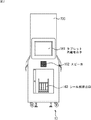
図7は、事後接客部13の正面側の構成例を示す図である。
FIG. 7 is a diagram illustrating a configuration example of the front side of the
事後接客部13の上方中央にはタブレット内蔵モニタ161が設けられる。タブレット内蔵モニタ161は、利用者の指などによって操作入力が可能なタブレットがLCDなどのモニタに重畳して設けられることによって構成される。タブレット内蔵モニタ161には、ミニゲームなどの事後接客処理に用いられる画面が表示される。
A
タブレット内蔵モニタ161の下にはスピーカ162が設けられ、スピーカ162の下にはシール紙排出口163が設けられる。
A
スピーカ162は、事後接客処理の案内音声、BGM、効果音等の音を出力する。
The
シール紙排出口163には、編集空間A2−1の利用者が編集処理を行うことによって作成した画像が印刷されたシール紙、または、編集空間A2−2の利用者が編集処理を行うことによって作成した画像が印刷されたシール紙が排出される。編集部12の内部にはプリンタが設けられており、画像の印刷がそのプリンタにより行われる。
In the sticker paper outlet 163, sticker paper on which an image created by the user of the editing space A2-1 is edited or printed by the user of the editing space A2-2 is edited. The sticker paper on which the created image is printed is discharged. A printer is provided inside the
次に、写真シール作成装置1の内部構成について説明する。図8は、写真シール作成装置1の内部の構成例を示すブロック図である。上述した構成と同じ構成には同じ符号を付してある。重複する説明については適宜省略する。
Next, the internal configuration of the photo
制御部201はCPU(Central Processing Unit)などよりなり、ROM(Read Only Memory)206や記憶部202に記憶されているプログラムを実行し、写真シール作成装置1の全体の動作を制御する。制御部201には、記憶部202、通信部203、ドライブ204、ROM206、RAM(Random Access Memory)207が接続される。制御部201には、撮影部208、編集部209、および事後接客部210の各構成も接続される。
The
記憶部202は、ハードディスクやフラッシュメモリなどの不揮発性の記憶媒体からなり、制御部201から供給された各種の設定情報を記憶する。記憶部202に記憶されている情報は制御部201により適宜読み出される。
The
通信部203は、インターネットなどのネットワークのインタフェースであり、制御部201による制御に従って外部の装置と通信を行う。
A
ドライブ204には、光ディスクや半導体メモリなどよりなるリムーバブルメディア205が適宜装着される。ドライブ204によりリムーバブルメディア205から読み出されたコンピュータプログラムやデータは、制御部201に供給され、記憶部202に記憶されたり、インストールされたりする。
A
ROM206には、制御部201において実行されるプログラムやデータが記憶されている。RAM207は、制御部201が処理するデータやプログラムを一時的に記憶する。
The
撮影部208は、撮影空間A1における撮影処理を行う構成である硬貨処理部221、背景制御部222、照明装置223、カメラ91、タッチパネルモニタ93、およびスピーカ224から構成される。
The
硬貨処理部221は、硬貨投入返却口87に対する硬貨の投入を検出する。硬貨処理部221は、例えば400円などの所定の金額分の硬貨が投入されたことを検出した場合、そのことを表す起動信号を制御部201に出力する。
The
背景制御部222は、制御部201より供給される背景制御信号に従って背景カーテンユニット25に収納されている背景カーテンの上げ下ろしを行う。背景カーテンの選択が利用者により手動で行われるようにしてもよい。
The
照明装置223は、撮影空間A1内の各ストロボの内部に設けられる蛍光灯であり、制御部201より供給される照明制御信号に従って発光する。上述したように、撮影空間A1には、天井ストロボユニット24のストロボの他に、撮影部21に設けられる上ストロボ82、左ストロボ83、右ストロボ84、足元ストロボ86と、背景部22に設けられる背面中央ストロボ101、背面左ストロボ102,背面右ストロボ103が設けられている。
The
また、照明装置223は、制御部201による制御に従って発光量を調整することによって、利用者が行っている撮影作業の段階に応じて撮影空間A1内の明るさを調整する。
Further, the
カメラ91は、制御部201による制御に従って撮影を行い、撮影によって得られた画像を制御部201に出力する。
The
編集部209Aは、編集空間A2−1における編集処理を行う構成として編集部12の正面側に設けられるタブレット内蔵モニタ131、タッチペン132A,132B、およびスピーカ231から構成される。編集部209Bも編集部209Aと同一の構成を有しており、編集空間A2−2における編集処理を行う。
The
タブレット内蔵モニタ131は、制御部201による制御に従って編集画面を表示し、編集画面に対する利用者の操作を検出する。利用者の操作の内容を表す信号は制御部201に供給され、編集対象の撮影画像の編集が行われる。
The tablet built-in
事後接客部210は、事後接客空間A3における事後接客処理を行う構成であるタブレット内蔵モニタ161、スピーカ162、印刷処理を行う構成であるプリンタ241、およびシール紙ユニット242から構成される。
The subsequent customer service unit 210 includes a tablet built-in
プリンタ241は、撮影画像、または編集処理によって得られた編集済みの画像を、プリンタ241に装着されたシール紙ユニット242に収納されているシール紙に印刷し、シール紙排出口163に排出する。
The printer 241 prints the photographed image or the edited image obtained by the editing process on the sticker paper stored in the
次に、制御部201について説明する。図9は、制御部201がROM206などに格納されているプログラムを実行することにより実現される機能ブロックの構成例を示している。
Next, the
制御部201は、写真シール作成ゲームを開始する際に投入される代金に関する処理や利用者を撮影する等の写真シール作成ゲームの撮影作業の工程に関する処理を行う撮影処理部301、撮影画像に対する落書き編集等の写真シール作成ゲームの編集作業の工程に関する処理を行う編集処理部302、シール紙の印刷等の写真シール作成ゲームの印刷の工程に関する処理を行う印刷処理部303、および、編集作業を終了した利用者を接客する写真シール作成ゲームの事後接客の工程に関する処理を行う事後接客処理部304を有する。
The
つまり、制御部201は、写真シール作成ゲームの各工程に関する処理の制御を行う。
That is, the
図10は、図9の撮影処理部301の詳細な構成例を示している。撮影処理部301は、操作入力処理部311、顔画像認識部312、画像処理部313、トリミング処理部314、表示制御部315、および管理部316から構成される。なお、以下、カメラ91により撮影された動画像と静止画像を区別する必要がない場合、すなわち、どちらにも共通する場合、単に画像(例えば、撮影画像)などと称する。
FIG. 10 shows a detailed configuration example of the
操作入力処理部311は、タッチパネルモニタ93を制御して、撮影コースを利用者に選択させる処理、合成用画像を利用者に選択させる処理、撮影された画像の中から編集対象とするもの(編集対象画像)を利用者に選択させる処理などを行う。
The operation
顔画像認識部312は、撮影される画像、あるいは、撮影された画像における所定の範囲において、目を検知するなどの方法で、利用者(被写体)の顔の位置を認識する。なお、顔画像認識部312は、顔の位置の認識結果より、被写体の人数を容易に認識することができる。ここでは、顔認識(顔検出)技術を用いる例について説明したが、被写体認識技術が用いられるようにしてもよい。
The face
画像処理部313は、顔画像認識部312により被写体の顔が認識された場合、撮影された画像のうち、認識された被写体の顔の範囲、または、予め設定された範囲の画像の画像処理を行う。具体的には、画像処理部313は、例えば、被写体の肌の色を、見栄えのよい肌の色に補正(変換)する画像処理をしたり、目検知が行われた場合には、例えば、被写体の目をぱっちりさせるように見栄えよく補正する画像処理を行う。
When the face of the subject is recognized by the face
トリミング処理部314は、必要に応じて、カメラ91により撮影された被写体の画像の一部分をトリミングする。また、トリミング処理部314は、トリミングした部分を拡大または縮小して、その画像と合成用画像を合成する。
The trimming
表示制御部315は、撮影された動画像や、合成用画像と合成された動画像(合成動画像)を、タッチパネルモニタ93(ライブビューモニタ)にライブビュー表示させる。表示される動画像は、被写体の顔として認識された部分に画像処理されている。
The
また、表示制御部315は、合成用画像と合成された静止画像(合成静止画像)を撮影結果としてタッチパネルモニタ93に表示させる。
In addition, the
管理部316は、カメラ91のシャッタータイミングを制御したり、各ゲーム時におけるシャッタ回数や経過時間を計測したりする。また、管理部316は、必要に応じて、利用者に各種の動作を促す案内、誘導に係る音声を、スピーカ224から出力させる。
The
次に、図11のフローチャートを参照して、写真シール作成ゲームを提供する写真シール作成装置1の処理について説明する。
Next, processing of the photo
ステップS1において、写真シール作成装置1の撮影処理部301は、所定の金額分の硬貨が投入されたか否かを硬貨処理部221から供給される信号に基づいて判定し、投入されたと判定するまで待機する。
In step S1, the
ステップS1において、硬貨が投入されたと判定された場合、ステップS2において、撮影処理部301は、撮影部208を制御し、図12を参照して後述する撮影処理を実行する。これにより、カメラ91に取り込まれた被写体の動画像をタッチパネルモニタ93にライブビュー表示させ、撮影空間A1にいる利用者が被写体として撮影される。撮影処理では、例えば、利用者の全身を撮影する全身撮影、または、利用者の顔若しくは上半身を撮影するアップ撮影が行われる。
If it is determined in step S1 that a coin has been inserted, in step S2, the
ステップS3において、撮影処理部301は、撮影空間A1にいる利用者に対して、編集空間A2−1または編集空間A2−2への移動を案内する。編集空間A2−1または編集空間A2−2への移動の案内は、撮影部208のタッチパネルモニタ93に画面を表示させることによって、または音声をスピーカ224から出力させることによって行われる。
In step S3, the
ステップS4において、編集処理部302は、編集空間A2−1と編集空間A2−2のうち、撮影処理を終えた利用者の移動先とした方の編集空間に対応する編集部209を制御し、編集処理を行う。具体的には、編集処理部302は、編集対象画像として選択された撮影画像に合成する合成用画像を利用者に選択させ、選択された合成用画像を撮影画像に合成させ、得られた合成画像に対して、利用者による編集操作に従って編集を行う。
In step S4, the
ステップS5において、編集処理部302は、編集空間A2−1または編集空間A2−2で編集処理を終えた利用者に対して事後接客空間A3への移動を案内する。事後接客空間A3への移動の案内は、タブレット内蔵モニタ131に画面を表示させることによって、または音声をスピーカ231から出力させることによって行われる。
In step S5, the
ステップS6において、印刷処理部303は、利用者により選択された画像をプリンタ241に出力してシール紙に印刷させる印刷処理を行う(開始する)。
In step S <b> 6, the
また、タブレット内蔵モニタ161に表示される、事後接客処理の開始ボタンが選択されると、ステップS7において、事後接客処理部304は、印刷終了待機中の利用者に対する事後接客処理を行う。具体的には、事後接客処理部304は、撮影画像や編集済みの画像を携帯端末に送信する携帯送信ゲーム処理を事後接客処理として行い、携帯端末の電子メールアドレスを直接入力することで画像を携帯端末に送信するか、非接触型ICと通信することで画像を携帯端末に送信するかを利用者に選択させる送信方法の選択画面や、送信する画像の選択画面をタブレット内蔵モニタ161に表示させ、利用者による操作に応じて画像を送信する。
Further, when the post-service processing start button displayed on the tablet built-in
印刷が終了すると、ステップS8において、事後接客処理部304は、印刷が終了した旨をタブレット内蔵モニタ161に表示させ、プリンタ241は、画像が印刷されたシール紙をシール紙排出口163に排出し、処理を終了させる。
When the printing is completed, in step S8, the post-service processing unit 304 displays that the printing has been completed on the tablet built-in
また、写真シール作成装置1は、撮影画像に対して所定の画像処理を行うことによって、撮影画像における被写体の見栄えを良くすることができる。
In addition, the photo
次に、図12のフローチャートを参照して、図11のステップS2の撮影処理の詳細な例について説明する。 Next, a detailed example of the photographing process in step S2 in FIG. 11 will be described with reference to the flowchart in FIG.
ステップS101において、撮影処理部301の操作入力処理部311は、タッチパネルモニタ93を用いて、撮影コース選択画面を表示させ、利用者に撮影コースの選択を促す。
In step S <b> 101, the operation
利用者が選択可能なコースとしては、例えば、利用者の全身を撮影する全身撮影コース、または、利用者の顔若しくは上半身を撮影するアップ撮影コースなどがある。 The course that can be selected by the user includes, for example, a whole body photographing course for photographing the whole body of the user or an up photographing course for photographing the user's face or upper body.
ステップS102において、撮影処理部301の管理部316は、撮影処理の経過時間tの計時を開始する。
In step S102, the
ステップS103において、操作入力処理部311は、タッチパネルモニタ93を用いて、合成用画像選択画面を表示させ、利用者に合成用画像の選択を促す。
In step S <b> 103, the operation
ここで、合成用画像とは、撮影画像に合成するための背景画像や前景画像のことである。なお、合成用画像選択画面には、合成用画像だけでなく、例えば、撮影画像における被写体の代わりのモデル画像と合成用画像が合成されたサンプル合成用画像が表示されてもよい。このサンプル合成用画像は、合成ではなく、もともとモデルが写りこんでいる画像であってもよい。 Here, the composition image is a background image or a foreground image to be combined with a captured image. Note that not only the synthesis image but also the sample synthesis image obtained by synthesizing the model image instead of the subject in the captured image and the synthesis image may be displayed on the synthesis image selection screen. The sample synthesis image may be an image in which a model is originally reflected instead of synthesis.
なお、ステップS103の処理は実行されないようにしてもよい。 Note that the process of step S103 may not be executed.
ステップS104において、管理部316は、カメラ91を制御して、被写体の動画像(被写体動画像)の取得を開始させる。
In step S <b> 104, the
ステップS105において、タッチパネルモニタ93を用いて、図13を参照して後述するライブビュー画面表示処理が実行される。これにより、タッチパネルモニタ93に、被写体動画像が表示され、被写体の位置をベストポジションに近づけるべく、利用者の誘導が行われる。なお、詳細は後述するが、ライブビュー画面表示処理においては、被写体動画像の一部が抽出されて、誘導用動画像としてタッチパネルモニタ93に表示される。 In step S105, the live view screen display process described later with reference to FIG. 13 is executed using the touch panel monitor 93. As a result, the subject moving image is displayed on the touch panel monitor 93, and the user is guided to bring the subject position closer to the best position. Although details will be described later, in the live view screen display process, a part of the subject moving image is extracted and displayed on the touch panel monitor 93 as a moving image for guidance.
ステップS106において、トリミング処理部314は、被写体動画像の一部を抽出する。ここでは、カメラ91により撮影された被写体動画像から、被写体(例えば、利用者の顔の部分)を含む一部の領域であって、上述の誘導用画像より小さい面積の領域が抽出される。このとき、抽出された画像は、撮影直前動画像としてステップS107の処理に伴ってタッチパネルモニタ93に表示される。
In step S106, the trimming
ステップS107においては、管理部316は、シャッタータイミングまでのカウントダウン(例えば、初期値が3秒)を開始する。このとき、管理部316は、表示制御部315を制御し、例えば「3,2,1,0」などとシャッタータイミングまでの残り秒数(カウント)に応じた画面を、タッチパネルモニタ93に表示させ、さらに、スピーカ224からもカウントダウンの音声を出力させて利用者にシャッタータイミングを通知し、カメラ91を制御してシャッタータイミングに同期して撮影を実行させる。
In step S107, the
また、ステップS107においてカウントダウンとともに、撮影直前動画像が表示される。すなわち、誘導用動画像に代えて、カウントダウンの際には撮影直前動画像が表示されることになる。 In step S107, the moving image immediately before shooting is displayed together with the countdown. That is, instead of the guidance moving image, the moving image immediately before shooting is displayed at the time of countdown.
つまり、被写体動画像の取得が開始されてから、撮影のカウントダウンが開始されるまでの期間では、タッチパネルモニタ93に誘導用動画像が表示されるようにし、撮影のカウントダウンが開始されると、タッチパネルモニタ93に撮影直前動画像が表示される。
That is, during the period from the start of acquisition of the subject moving image to the start of shooting countdown, the guide moving image is displayed on the touch panel monitor 93, and when the shooting countdown is started, the touch panel is displayed. A moving image immediately before shooting is displayed on the
撮影が実行されたことにより、トリミング処理部314によりカメラ91から出力される被写体の画像の一部が抽出されて静止画像として出力され、保存される。また、合成用画像と合成する場合には、トリミング処理部314によりカメラ91から出力される被写体の画像の一部が抽出されて静止画像として出力され、合成用画像と合成されて、保存される。ここで、保存された静止画像が、後の処理において撮影画像として取り扱われる。
When the photographing is executed, a part of the subject image output from the
ステップS108において、表示制御部315は、タッチパネルモニタ93を用いて、撮影結果画像を表示させる。すなわち、撮影のタイミングで取得された撮影画像(上述のように保存された静止画像)が、タッチパネルモニタ93に撮影結果画像として表示される。
In step S <b> 108, the
ステップS109において、管理部316は、撮影回数が所定数X(例えば、6回)に到達したか否かを判定する。そして、撮影回数が所定数Xに到達していないと判定された場合、処理はステップS105に戻されて、それ以降が繰り返される。その後、ステップS109において、撮影回数が所定数Xに到達したと判定された場合、処理はステップS110に進められる。
In step S109, the
ステップS110において、管理部316は、経過時間tが所定時間T(例えば、5分間)を経過したか否かを判定する。ここで、経過時間tが所定時間Tを経過していないと判定された場合、例えば、ボーナス撮影(所定数X回を超える撮影)が許可されて、処理はステップS105に戻される。
In step S110, the
反対に、経過時間tが所定時間Tを経過していると判定された場合、処理はステップS111に進められる。 On the contrary, if it is determined that the elapsed time t has passed the predetermined time T, the process proceeds to step S111.
ステップS111において、操作入力処理部311は、タッチパネルモニタ93を用いて、編集対象画像選択画面を表示させ、利用者に対し、複数の撮影画像の中から複数の編集対象画像を選択するように促す。ここで、編集対象画像とは、編集処理を施した後にシール紙に印刷する画像を指す。
In step S111, the operation
このようにして撮影処理が実行される。 In this way, the photographing process is executed.
次に、図13のフローチャートを参照して、図12のステップS105のライブビュー画面表示処理の詳細な例について説明する。 Next, a detailed example of the live view screen display process in step S105 of FIG. 12 will be described with reference to the flowchart of FIG.
ステップS151において、カメラ91は、被写体動画像を取得する。
In step S151, the
ステップS152において、顔画像認識部212は、ステップS131で取得された被写体動画像において利用者(被写体)の顔の位置を認識する。 In step S152, the face image recognition unit 212 recognizes the position of the face of the user (subject) in the subject moving image acquired in step S131.
ステップS153において、画像処理部213は、被写体動画像における認識された被写体の顔の範囲を対象枠として設定する。 In step S153, the image processing unit 213 sets the recognized face range of the subject in the subject moving image as the target frame.
ステップS154において、トリミング処理部314は、ステップS151の処理で取得した被写体動画像の一部である誘導用動画像を抽出する。
In step S154, the trimming
ステップS155において、表示制御部315は、ステップS154の処理で抽出された誘導用動画像を、タッチパネルモニタ93に表示する。
In step S155, the
ステップS156において、表示制御部315は、目標枠と対象枠の位置を比較する。ここで、対象枠は、ステップS153の処理で設定された対象枠とされ、被写体動画像における被写体の顔の範囲とされる。一方、目標枠は、例えば、ステップS103の処理で選択された合成用画像に対応するサンプル合成用画像におけるモデルの顔の範囲とされる。
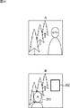
In step S156, the
例えば、図14Aに示されるようなサンプル合成用画像にモデルが写っているものする。この場合、図14Bに示されるようなライブビュー画面において、被写体である利用者Aの顔の範囲(図中の点線の矩形)が対象枠351として設定され、サンプル合成用画像におけるモデルの顔の範囲(図中の実線の矩形)が目標枠352として設定される。
For example, it is assumed that the model is shown in the sample composition image as shown in FIG. 14A. In this case, on the live view screen as shown in FIG. 14B, the range of the face of the user A who is the subject (dotted rectangle in the figure) is set as the
すなわち、目標枠352は、ステップS103の処理で選択された合成用画像を合成する場合、理想的な顔の位置および大きさを特定するものであり、目標枠352の中に顔が配置された撮影画像は、当該合成用画像を合成する場合に理想的な構図の画像となる。
In other words, the
なお、目標枠352と対象枠351は、例えば、常に各辺の長さの比率が一定の長方形とされるものとする。すなわち、被写体のカメラ91からの距離に応じて、対象枠351の面積は変化するが、常に目標枠352と相似の形状の対象枠が設定されるものとする。
It is assumed that the
ステップS157において、表示制御部315は、ベストポジションであるか否かを判定する。このとき、例えば、目標枠352と対象枠351が合致した場合、被写体の位置がベストポジションであると判定される。
In step S157, the
例えば、対象枠351の長方形の4つの頂点の座標が特定され、目標枠352の長方形における対応する頂点との間の距離が計算される。そして、計算された距離が予め設定された閾値より小さい場合、目標枠352と対象枠351が合致した(被写体の位置がベストポジションである)と判定される。
For example, the coordinates of four vertices of the rectangle of the
あるいはまた、目標枠352の垂直方向の一辺の長さと、対象枠351の垂直方向の一辺の長さとの差分の絶対値が閾値と比較されるようにし、この差分の絶対値が閾値より小さい場合、目標枠352と対象枠351が合致した(被写体の位置がベストポジションである)と判定されるようにしてもよい。
Alternatively, the absolute value of the difference between the length of one side of the
ここでは、目標枠352と対象枠351の合致を検出することにより、ベストポジションを検出する例について説明するが、これとは異なる方式でベストポジションが検出されるようにしてもよい。例えば、カメラ91により撮影された画像の中で利用者の顔の大きさ(面積)が所定の範囲内であることが検出されて、ベストポジションが検出されるようにしてもよい。この場合、例えば、ステップS153の処理などは実行されないようにしてもよい。
Here, an example in which the best position is detected by detecting a match between the
ステップS157において、ベストポジションではないと判定された場合、処理は、ステップS158に進む。 If it is determined in step S157 that the position is not the best position, the process proceeds to step S158.
ステップS158において、表示制御部315および管理部316により、誘導情報が提示される。このとき、例えば、ステップS156での比較の結果に基づいて、目標枠と対象枠を合致させるために、利用者が移動すべき方向が特定される。例えば、利用者が、カメラ91に向かって前後左右のどの方向に移動すべきかが特定される。
In step S158, guidance information is presented by the
そして、例えば、「右後方に移動してね!」、「もっと前に来てね!」などの文言、または、移動方向を表す矢印などの記号が誘導情報として提示される。誘導情報は、例えば、タッチパネルモニタ93に表示されるようにしてもよいし、スピーカ224から音声として出力されるようにしてもよいし、それらが同時に行われるようにしてもよい。
Then, for example, words such as “Move to the right rear!” And “Come ahead!” Or a symbol such as an arrow indicating the moving direction is presented as guidance information. For example, the guidance information may be displayed on the touch panel monitor 93, may be output as sound from the
ステップS158の処理の後、処理は、ステップS154に戻り、それ以降の処理が繰り返し実行される。 After the process of step S158, the process returns to step S154, and the subsequent processes are repeatedly executed.
一方、ステップS157において、ベストポジションであると判定された場合、処理は、ステップS159に進む。 On the other hand, if it is determined in step S157 that the position is the best position, the process proceeds to step S159.
ステップS159において、表示制御部315および管理部316により、ベストポジションである旨が提示される。このとき、例えば、タッチパネルモニタ93に表示される誘導用動画像の中の利用者の顔に近い部分に「BEST!」という文字列が表示される。あるいはまた、誘導用動画像の中の所定の部分を明滅させたり、スピーカ224から、被写体の位置がベストポジションである旨の音声が出力されるようにしてもよい。さらに、それらが同時に行われるようにしてもよい。
In step S159, the
このようにして、ライブビュー画面表示処理が実行される。 In this way, live view screen display processing is executed.
図15は、図12の撮影処理および図13のライブビュー画面表示処理において、カメラ91から出力される画像の例を示す図である。すなわち、図15に示される画像は、図12のステップS104の処理で、被写体動画像の取得が開始されてから、撮影処理が終了するまで、カメラ91から出力される画像401の例を示している。この例では、2人の利用者を撮影した画像401が示されており、図12のステップS101では、利用者の上半身を撮影するアップ撮影コースが選択されて画像401が得られたものとする。
FIG. 15 is a diagram illustrating an example of an image output from the
図15には、トリミング処理部314により抽出される領域を表す枠411乃至枠413が示されている。枠411乃至枠413は、いずれも長方形の枠とされ、枠411は枠412より面積が大きく、枠412は枠413より面積が大きい。
FIG. 15
枠411は、誘導用動画像に対応する領域を表すものとされる。枠412は、撮影直前動画像に対応する領域を表すものとされる。枠413は、撮影結果画像に対応する領域を表すものとされる。なお、撮影結果画像は、その後の処理において、編集対象画像、編集済み画像として用いられることになる。
A
図16は、図15の画像401から抽出された誘導用動画像、撮影直前動画像、および撮影結果画像の例を示す図である。図16Aは誘導用動画像であり、図16Bは撮影直前動画像であり、図16Cは撮影結果画像である。
FIG. 16 is a diagram illustrating an example of a guide moving image, a moving image just before shooting, and a shooting result image extracted from the
図16Aの誘導用動画像は、図15の枠411に対応して抽出された画像なので、図16Bまたは図16Cと比較して面積の大きい画像とされている。一方で、図16Aの誘導用動画像全体に占める被写体(2人の利用者)の割合は小さくなっている。
The guidance moving image in FIG. 16A is an image extracted corresponding to the
図16Cの撮影結果画像は、図15の枠413に対応して抽出された画像なので、図16Aまたは図16Bと比較して面積の小さい画像とされている。一方で、図16Cの撮影結果画像全体に占める被写体(2人の利用者)の割合は大きくなっている。
The captured image of FIG. 16C is an image extracted corresponding to the
図16Bの撮影直前動画像は、図15の枠412に対応して抽出された画像なので、図16Aおよび図16Cの中間の面積の画像とされている。また、図16Bの撮影直前動画像全体に占める被写体(2人の利用者)の割合も図16Aおよび図16Cの中間となっている。
The moving image immediately before shooting in FIG. 16B is an image extracted corresponding to the
例えば、図16Aの誘導用動画像は、画像401(原画像と称することにする)の約80%の面積の長方形により構成され、図16Bの撮影直前動画像は、原画像の約70%の面積の長方形により構成され、図16Cの撮影結果画像は、原画像の約60%の面積の長方形により構成される。 For example, the guide moving image in FIG. 16A is configured by a rectangle having an area of about 80% of the image 401 (referred to as an original image), and the moving image immediately before shooting in FIG. 16B is about 70% of the original image. The imaging result image in FIG. 16C is configured by a rectangle having an area of about 60% of the original image.
なお、図16Bや図16Cを、タッチパネルモニタ93のライブビュー画面の表示領域に合わせて、拡大して表示するようにしてもよい。また、図16Bまたは図16Cは、実際に図16Aより小さいサイズの画像としてタッチパネルモニタ93のライブビュー画面の表示領域に表示され、サイズの差異部分は白色やグレーで表示されるようにしてもよい。 16B and 16C may be enlarged and displayed in accordance with the display area of the live view screen of the touch panel monitor 93. 16B or 16C may be displayed in the display area of the live view screen of the touch panel monitor 93 as an image that is actually smaller than FIG. 16A, and the difference in size may be displayed in white or gray. .
また、図15と図16を参照して上述した例では、誘導用動画像、撮影直前動画像、および撮影結果画像において、利用者の顔が、画像の中の上半分の領域に入るように、図15の枠411乃至枠413がトリミングされている。しかしながら、例えば、誘導用動画像、撮影直前動画像、および撮影結果画像のそれぞれにおいて利用者の顔が、画像の中で異なる位置に表示されるようにしてもよい。例えば、誘導用動画像、および撮影直前動画像では、利用者の顔が、画像の中の上半分の領域に入るように、図15の枠411および枠412がトリミングされるようにし、撮影直前動画像では、利用者の顔が、画像の中央の領域に入るように、図15の枠413がトリミングされるようにしてもよい。
In the example described above with reference to FIGS. 15 and 16, the user's face is included in the upper half of the image in the guidance moving image, the moving image immediately before shooting, and the shooting result image. The
すなわち、図15と図16を参照して上述した例では、原画像の中の同一の位置(図中左側の利用者の肩付近)を中心として誘導用動画像、撮影直前動画像、および撮影結果画像に対応する枠411乃至枠413がトリミングされていた。しかし、例えば、顔認証技術などを用いて、原画像の中での顔の位置情報を取得することにより、誘導用動画像、撮影直前動画像、および撮影結果画のそれぞれにおいてトリミングされる枠の中心となる位置が変更されるようにしてもよい。
That is, in the example described above with reference to FIGS. 15 and 16, the guide moving image, the moving image immediately before shooting, and the shooting are performed around the same position in the original image (near the user's shoulder on the left side in the drawing). The
つまり、誘導用動画像、撮影直前動画像、および撮影結果画像に対応する枠411乃至枠413のそれぞれの領域が可変的にトリミングされるようにしてもよい。
That is, the areas of the
例えば、撮影直前動画像または撮影結果画像など、画像全体に占める被写体の割合が大きい画像においては、被写体の一部(例えば、利用者の頭頂部など)が切れて表示されてしまうことがある。枠411乃至枠413のそれぞれの領域が可変的にトリミングされるようにすることで、被写体の一部が切れて表示されることを回避することができる。
For example, in an image having a large proportion of the subject in the entire image, such as a moving image immediately before photographing or a photographing result image, a part of the subject (for example, the user's head) may be cut off and displayed. By making each region of the
アップ撮影コースが選択された場合、図16Cに示されるように、被写体である2人の利用者の上半身を充分に大きく表示した撮影結果画像を得る必要がある。このため、ライブビュー画面表示処理において、ベストポジションは、カメラ91に十分に近い位置とされ、利用者をカメラ91に近づけるように誘導する必要がある。
When the up shooting course is selected, as shown in FIG. 16C, it is necessary to obtain a shooting result image in which the upper bodies of the two users who are the subjects are displayed sufficiently large. For this reason, in the live view screen display processing, the best position is a position sufficiently close to the
図13を参照して上述したように、ライブビュー画面表示処理において、利用者はタッチパネルモニタ93に表示された誘導用動画像を見ながら、誘導情報に従って撮影空間A1内を移動することになる。このとき、一般的な利用者は小顔に写りたいため、カメラ91に近づくことをためらう傾向がある。
As described above with reference to FIG. 13, in the live view screen display process, the user moves within the imaging space A <b> 1 according to the guidance information while viewing the guidance moving image displayed on the touch panel monitor 93. At this time, a general user tends to hesitate to approach the
つまり、利用者には写真に写った自分の顔をできるだけ小さく見せたいという願望があり、例えば、「もっと前に来てね!」などの誘導情報を提示しても、なかなかカメラ91に近づこうとしない利用者も多い。
In other words, the user has a desire to make his face shown in the photograph as small as possible. For example, even if he / she presents guidance information such as “Come ahead”, he tries to get closer to the
従来の技術では、例えば、ライブビュー画面表示処理では、常に同じ大きさの被写体動画像がタッチパネルモニタ93に表示されていた。例えば、従来は、誘導用動画像として図16Bと同じ大きさの領域が抽出され、被写体動画像が表示されていた。このため、被写体動画像に占める自分の顔の割合が大きくなり、自分の顔が大きく感じられるので、「もっと前に来てね!」などの誘導情報を提示しても、なかなかカメラ91に近づこうとしない利用者が多かった。
In the conventional technology, for example, in the live view screen display process, a subject moving image having the same size is always displayed on the touch panel monitor 93. For example, conventionally, an area having the same size as that of FIG. 16B is extracted as a guidance moving image, and a subject moving image is displayed. For this reason, the ratio of one's face to the subject moving image increases, and the person's face feels larger, so even if guidance information such as “Come ahead” is presented, it is quite easy to approach the
そこで、本発明では、個々の静止画像が撮影されるまでの期間を2つの期間に分類し、被写体動画像を取得の取得が開始されてから、撮影のカウントダウンである3,2,1が開始されるまでの期間では、タッチパネルモニタ93に誘導用動画像(図15の枠411)である図16Aが表示されるようにし、撮影のカウントダウンである3,2,1が開始されると、タッチパネルモニタ93に撮影直前動画像(図15の枠412)である図16Bが表示されるようにした。そして、撮影処理の結果、最終的に得られた画像(静止画像)として、タッチパネルモニタ93に撮影結果画像である図16Cが表示されるようにした。
Therefore, in the present invention, the period until each still image is shot is classified into two periods, and the acquisition of the subject moving image is started, and then the
すなわち、図16Bの撮影直前動画像より面積の大きい画像を、画像401から抽出し、図16Aの誘導用動画像としてタッチパネルモニタ93に表示されるようにした。図16Aの誘導用動画像の場合、図16Bの撮影直前動画像の場合と比較して、被写体動画像に占める自分の顔の割合が小さくなるので、自分の顔を小さく感じさせることができ、出来上がりの画像(撮影結果画像)では、図16Cに示されるように、顔が大きく写り、写真シールとして相応しい構図の画像を得ることができる。
That is, an image having a larger area than the moving image immediately before photographing in FIG. 16B is extracted from the
あるいはまた、撮影処理の結果、最終的に得られた画像(静止画像)として、撮影結果画像である図16Cがタッチパネルモニタ93に表示されないようにしてもよい。すなわち、図12のステップS108でタッチパネルモニタ93に撮影結果画像が表示されることになるが、このとき表示される撮影結果画像が図16Cとは異なるサイズの画像とされるようにしてもよい。 Alternatively, FIG. 16C that is a photographing result image may not be displayed on the touch panel monitor 93 as an image (still image) finally obtained as a result of the photographing process. That is, the shooting result image is displayed on the touch panel monitor 93 in step S108 in FIG. 12, but the shooting result image displayed at this time may be an image having a size different from that in FIG. 16C.
図12のステップS108では、タッチパネルモニタ93に、例えば、「こんなふうに撮れたよ!」というメッセージとともに撮影結果画像が表示される。この際、表示される撮影結果画像が、例えば、図15の枠412に対応して抽出されるようにしてもよい。
In step S108 of FIG. 12, the captured result image is displayed on the touch panel monitor 93 together with, for example, a message “I have taken it like this!”. At this time, the displayed photographing result image may be extracted corresponding to the
例えば、上述した場合と同様に、被写体動画像を取得の取得が開始されてから、撮影のカウントダウンである3,2,1が開始されるまでの期間では、タッチパネルモニタ93に誘導用動画像(図15の枠411)である図16Aが表示され、撮影のカウントダウンである3,2,1が開始されると、タッチパネルモニタ93に撮影直前動画像(図15の枠412)である図16Bが表示される。しかし、上述した場合とは異なり、撮影結果画像として、図15の枠412に対応して抽出された、図16Bに示されるものと同じサイズの静止画像が表示されるようにしてもよい。そして、例えば、図11のステップS4の編集処理において、編集空間A2−1または編集空間A2−2のタブレット内蔵モニタ131に表示される編集対象画像として、図16Cに示される画像と同じサイズの画像が表示されるようにしてもよい。すなわち、編集対象画像、編集済み画像、携帯端末に送信する画像、シール紙に印刷される画像などは、図16Cに示される画像と同じサイズの画像となる。
For example, as in the case described above, during the period from the start of acquisition of the subject moving image to the start of
誘導用動画像として、図16Aに示されるように、顔が小さく写った画像が表示されるようにしても、撮影処理が終了する前に、図16Cに示されるように、顔が大きく写った画像が表示されると、利用者は無意識にカメラ91から遠ざかることがある。例えば、第1回目の撮影に対応する撮影結果画像として、図16Cに示されるように、顔が大きく写った画像が表示されると、第2回目の撮影において利用者が無意識にカメラ91から遠ざかってしまうことがある。
Even if an image showing a small face is displayed as the guide moving image as shown in FIG. 16A, the face is shown large as shown in FIG. 16C before the photographing process is completed. When the image is displayed, the user may unconsciously move away from the
このため、例えば、撮影処理が終了するまでは、図16Cに示されるように、顔が大きく写った画像が表示されないようにしてもよい。このようにすることで、例えば、利用者を、より確実にカメラ91に近づけるようにすることができるので、写真シールとして相応しい構図の画像を得ることができる。
Therefore, for example, as shown in FIG. 16C, an image with a large face may not be displayed until the photographing process is completed. In this way, for example, the user can be brought closer to the
あるいはまた、編集対象画像、編集済み画像として、タブレット内蔵モニタ131に、図15の枠412に対応して抽出された、図16Bに示されるものと同じサイズの静止画像が表示されるようにしてもよい。そして、携帯端末に送信する画像、シール紙に印刷される画像などは、図15の枠413に対応して抽出された、図16Cに示される画像と同じサイズの画像となるようにしてもよい。
Alternatively, the still image of the same size as that shown in FIG. 16B extracted corresponding to the
このようにすることで、編集処理中も顔が小さく写った画像が表示されるので、利用者は顔が小さく写っていることを確認し、安心して編集を楽しむことができる。一方で、シール紙に印刷される画像などは、顔が大きく写った画像とされ、構図のよい画像を提供することができる。 In this way, an image with a small face is displayed even during the editing process, so that the user can confirm that the face is small and enjoy editing with peace of mind. On the other hand, the image printed on the sticker paper is an image with a large face, and an image with a good composition can be provided.
なお、編集対象画像、編集済み画像として、タブレット内蔵モニタ131に図16Bに示されるものと同じサイズの静止画像が表示されるようにする場合、シール紙に印刷される画像などは、編集処理後に、図16Cに示される画像と同じサイズにトリミングされることになる。従って、編集対象画像、編集済み画像として表示された画像の外周付近の領域に編集情報が入力された(例えば、ペンで落書きされた)としても、トリミングされて欠落してしまうことになる。このため、編集対象画像、編集済み画像として表示された画像の外周付近の領域を、編集入力対象外領域とし、編集入力が受け付けられないようにしてもよい。この際、編集入力対象外領域を、利用者から見て目立たない薄いグレーなどの色で表示するようにしてもよい。
When a still image having the same size as that shown in FIG. 16B is displayed on the tablet built-in
さらに、編集対象画像、編集済み画像、および携帯端末に送信する画像は、図15の枠412に対応して抽出された、図16Bに示されるものと同じサイズの静止画像が表示されるようにし、シール紙に印刷される画像は、図15の枠413に対応して抽出された、図16Cに示される画像と同じサイズの画像となるようにしてもよい。
Furthermore, the editing target image, the edited image, and the image to be transmitted to the mobile terminal are displayed so that a still image having the same size as that shown in FIG. 16B extracted corresponding to the
携帯端末に送信する画像は、携帯端末のディスプレイに表示されるものであり、例えば、十分な大きさに拡大して表示することも可能である。このため、例えば、携帯端末に送信する画像はあえて、顔が小さく写った画像とされるようにしてもよい。 The image transmitted to the mobile terminal is displayed on the display of the mobile terminal, and can be displayed in an enlarged size, for example. For this reason, for example, the image to be transmitted to the portable terminal may be an image with a small face.
従って、本発明によれば、利用者が意図する構図の画像を提供することができる。 Therefore, according to the present invention, an image having a composition intended by the user can be provided.
なお、図15と図16を参照して上述したように、原画像から、誘導用動画像、撮影直前動画像、および撮影結果画像を、それぞれ異なる面積の画像として抽出する処理は、例えば、図12のステップS101で選択された撮影コースに応じて行われるようにしてもよい。 Note that, as described above with reference to FIGS. 15 and 16, the process of extracting the guidance moving image, the moving image immediately before shooting, and the shooting result image as images of different areas from the original image is illustrated in FIG. It may be performed in accordance with the shooting course selected in step S101.
例えば、アップ撮影コースが選択された場合、誘導用動画像、撮影直前動画像、および撮影結果画像を、それぞれ異なる面積の画像として抽出するようにし、全身撮影コースが選択された場合、誘導用動画像、撮影直前動画像、および撮影結果画像を、それぞれ同じ面積の画像として抽出するようにしてもよい。 For example, when the up shooting course is selected, the moving image for guidance, the moving image immediately before shooting, and the shooting result image are extracted as images of different areas, and when the whole body shooting course is selected, the moving image for guidance The image, the moving image immediately before shooting, and the shooting result image may be extracted as images of the same area.
ところで、上述した一連の処理は、ハードウェアにより実行させることもできるし、ソフトウェアにより実行させることもできる。上述した一連の処理をソフトウェアにより実行させる場合には、そのソフトウェアを構成するプログラムが、ネットワークや記録媒体からインストールされる。 By the way, the above-described series of processes can be executed by hardware or can be executed by software. When the above-described series of processing is executed by software, a program constituting the software is installed from a network or a recording medium.
この記録媒体は、例えば、図8に示されるように、装置本体とは別に、写真シール作成装置1の管理者にプログラムを配信するために配布される、プログラムが記録されている磁気ディスク(フレキシブルディスクを含む)、光ディスク(CD-ROMおよびDVDを含む)、光磁気ディスク(MDを含む)、もしくは半導体メモリなどよりなるリムーバブルメディア205により構成されるだけでなく、装置本体に予め組み込まれた状態で管理者に配信される、プログラムが記録されているROM206や、記憶部202に含まれるハードディスクなどで構成される。
For example, as shown in FIG. 8, the recording medium is distributed to distribute the program to the administrator of the photo
なお、本明細書において、記録媒体に記録されるプログラムを記述するステップは、記載された順序に沿って時系列的に行われる処理はもちろん、必ずしも時系列的に処理されなくとも、並列的あるいは個別に実行される処理をも含むものである。 In the present specification, the step of describing the program recorded on the recording medium is not limited to the processing performed in chronological order according to the described order, but is not necessarily performed in chronological order. It also includes processes that are executed individually.
以上において、印刷媒体は、シール紙や写真紙に限られるものではなく、例えば、所定のサイズの紙やフィルム、ポスター用の紙、テレホンカードなどのカード、あるいは、Tシャツなどの布地などに印刷するようにしてもよい。 In the above, the printing medium is not limited to sticker paper or photographic paper. For example, printing on a predetermined size of paper or film, poster paper, a card such as a telephone card, or a cloth such as a T-shirt. You may make it do.
また、本発明の実施の形態は、上述した実施の形態に限定されるものではなく、本発明の要旨を逸脱しない範囲において種々の変更が可能である。 The embodiments of the present invention are not limited to the above-described embodiments, and various modifications can be made without departing from the scope of the present invention.
1 写真シール作成装置
11 撮影ユニット
12 編集部
13 事後接客部
201 制御部
208 撮影部
209 編集部
210 事後接客部
301 撮影処理部
302 編集処理部
303 印刷処理部
304 事後接客処理部
311 操作入力部
312 顔画像認識部
313 画像処理部
314 トリミング処理部
315 表示制御部
316 管理部
DESCRIPTION OF
Claims (5)
撮影空間内で前記被写体を含んだ所定の範囲の画像を撮影する撮影手段と、
前記撮影手段により撮影された画像である原画像から、前記被写体を含む一部の領域を抽出して表示するように制御する画像表示制御手段と、
前記撮影空間内における前記利用者の理想的な位置に係る情報を前記利用者に提示する位置情報提示手段と
を備え、
前記撮影手段により静止画像が撮影されるまでの期間を、前記撮影手段が動画像の撮影を開始した後の所定の時間に対応する第1の期間と、前記撮影手段により前記静止画像が撮影される前の所定の時間に対応し、前記第1の期間よりも後に設定されている第2の期間に分類し、
前記画像表示制御手段は、
前記第1の期間において、原画像から抽出される領域を第1の面積の領域として抽出し、
前記第2の期間において、原画像から抽出される領域を第2の面積の領域として抽出し、
前記第1の期間において原画像から抽出される画像に占める前記被写体の面積の割合が、前記第2の期間において原画像から抽出される画像に占める前記被写体の面積の割合より小さい
写真シール作成装置。 An image with the user as a subject is acquired, an editing input operation is performed for inputting editing information on the acquired image, and the obtained edited user image is provided to the user. In the photo sticker creation device,
Photographing means for photographing an image of a predetermined range including the subject in a photographing space;
Image display control means for controlling to extract and display a part of the region including the subject from the original image which is an image photographed by the photographing means;
Position information presenting means for presenting information related to the ideal position of the user in the photographing space to the user;
The period until the still image is captured by the image capturing unit is the first period corresponding to a predetermined time after the image capturing unit starts capturing the moving image, and the still image is captured by the image capturing unit. Categorizing into a second period set after the first period,
The image display control means includes
In the first period, a region extracted from the original image is extracted as a region having a first area ;
In the second period, a region extracted from the original image is extracted as a region having a second area ,
The photo sticker creating apparatus in which the ratio of the area of the subject in the image extracted from the original image in the first period is smaller than the ratio of the area of the subject in the image extracted from the original image in the second period. .
前記画像表示制御手段は、
前記第1の期間において、原画像から抽出される領域を第1の面積の領域として抽出し、
前記第2の期間において、原画像から抽出される領域を、前記第1の面積として抽出された領域の中に含まれ、前記第1の面積より小さい第2の面積の領域として抽出し、
前記利用者により、第2の撮影コースが選択されて前記撮影手段による撮影が行われる場合、
前記画像表示制御手段は、前記第2の期間において、前記第1の面積と同じ大きさの第2の面積の領域を前記原画像から抽出する
請求項1に記載の写真シール作成装置。 When the first shooting course is selected by the user and shooting by the shooting means is performed,
The image display control means includes
In the first period, a region extracted from the original image is extracted as a region having a first area;
In the second period, the region extracted from the original image is included in the region extracted as the first area, and is extracted as a region having a second area smaller than the first area,
When the second photographing course is selected by the user and photographing by the photographing means is performed,
2. The photo sticker creating apparatus according to claim 1 , wherein the image display control unit extracts a region having a second area having the same size as the first area from the original image in the second period.
前記第2の撮影コースは、前記利用者の全身の画像を撮影する撮影コースである
請求項2に記載の写真シール作成装置。 The first shooting course is a shooting course for shooting an image of the user's face or upper body up,
The photo sticker creating apparatus according to claim 2 , wherein the second shooting course is a shooting course for shooting an image of the whole body of the user.
撮影手段が、撮影空間内で前記被写体を含んだ所定の範囲の画像を撮影し、
画像表示制御手段が、前記撮影された画像である原画像から、前記被写体を含む一部の領域を抽出して表示し、
位置情報提示手段が、前記撮影空間内における前記利用者の理想的な位置に係る情報を前記利用者に提示するように制御するステップを含み、
前記撮影手段により静止画像が撮影されるまでの期間を、前記撮影手段が動画像の撮影を開始した後の所定の時間に対応する第1の期間と、前記撮影手段により前記静止画像が撮影される前の所定の時間に対応し、前記第1の期間よりも後に設定されている第2の期間に分類し、
前記画像表示制御手段は、
前記第1の期間において、原画像から抽出される領域を第1の面積の領域として抽出し、
前記第2の期間において、原画像から抽出される領域を第2の面積の領域として抽出し、
前記第1の期間において原画像から抽出される画像に占める前記被写体の面積の割合が、前記第2の期間において原画像から抽出される画像に占める前記被写体の面積の割合より小さくなるように抽出する
ステップを含む写真シール作成方法。 An image with the user as a subject is acquired, an editing input operation is performed for inputting editing information on the acquired image, and the obtained edited user image is provided to the user. In the photo sticker creating method of the photo sticker creating device,
The photographing means photographs an image of a predetermined range including the subject in the photographing space,
The image display control means extracts and displays a part of the region including the subject from the original image that is the captured image,
Position information presenting means includes a step of controlling to present to the user information related to the ideal position of the user in the shooting space;
The period until the still image is captured by the image capturing unit is the first period corresponding to a predetermined time after the image capturing unit starts capturing the moving image, and the still image is captured by the image capturing unit. Categorizing into a second period set after the first period,
The image display control means includes
In the first period, a region extracted from the original image is extracted as a region having a first area;
In the second period, a region extracted from the original image is extracted as a second area region;
Extraction is performed so that the ratio of the area of the subject in the image extracted from the original image in the first period is smaller than the ratio of the area of the subject in the image extracted from the original image in the second period. Do
Photo sticker creation method including steps .
撮影手段が、撮影空間内で前記被写体を含んだ所定の範囲の画像を撮影し、
画像表示制御手段が、前記撮影された画像である原画像から、前記被写体を含む一部の領域を抽出して表示するように制御し、
位置情報提示手段が、前記撮影空間内における前記利用者の理想的な位置に係る情報を前記利用者に提示するように制御するステップを含む処理をコンピュータに実行させ、
前記撮影手段により静止画像が撮影されるまでの期間を、前記撮影手段が動画像の撮影を開始した後の所定の時間に対応する第1の期間と、前記撮影手段により前記静止画像が撮影される前の所定の時間に対応し、前記第1の期間よりも後に設定されている第2の期間に分類し、
前記画像表示制御手段は、
前記第1の期間において、原画像から抽出される領域を第1の面積の領域として抽出し、
前記第2の期間において、原画像から抽出される領域を第2の面積の領域として抽出し、
前記第1の期間において原画像から抽出される画像に占める前記被写体の面積の割合が、前記第2の期間において原画像から抽出される画像に占める前記被写体の面積の割合より小さくなるように抽出する
ステップを含む
プログラム。 An image with the user as a subject is acquired, an editing input operation is performed for inputting editing information on the acquired image, and the obtained edited user image is provided to the user. A program for causing a computer to execute processing in the photo sticker creating apparatus,
The photographing means photographs an image of a predetermined range including the subject in the photographing space,
The image display control means controls to extract and display a part of the region including the subject from the original image that is the captured image,
The position information presenting means causes the computer to execute a process including a step of controlling the user to present information related to the ideal position of the user in the shooting space to the user,
The period until the still image is captured by the image capturing unit is the first period corresponding to a predetermined time after the image capturing unit starts capturing the moving image, and the still image is captured by the image capturing unit. Categorizing into a second period set after the first period,
The image display control means includes
In the first period, a region extracted from the original image is extracted as a region having a first area;
In the second period, a region extracted from the original image is extracted as a second area region;
Extraction is performed so that the ratio of the area of the subject in the image extracted from the original image in the first period is smaller than the ratio of the area of the subject in the image extracted from the original image in the second period. Do
A program that includes steps .
Priority Applications (1)
| Application Number | Priority Date | Filing Date | Title |
|---|---|---|---|
| JP2013088837A JP6201397B2 (en) | 2013-04-19 | 2013-04-19 | Photo sticker creation apparatus and method, and program |
Applications Claiming Priority (1)
| Application Number | Priority Date | Filing Date | Title |
|---|---|---|---|
| JP2013088837A JP6201397B2 (en) | 2013-04-19 | 2013-04-19 | Photo sticker creation apparatus and method, and program |
Related Child Applications (1)
| Application Number | Title | Priority Date | Filing Date |
|---|---|---|---|
| JP2017101967A Division JP6414276B2 (en) | 2017-05-23 | 2017-05-23 | Photo sticker creation apparatus and method, and program |
Publications (2)
| Publication Number | Publication Date |
|---|---|
| JP2014212489A JP2014212489A (en) | 2014-11-13 |
| JP6201397B2 true JP6201397B2 (en) | 2017-09-27 |
Family
ID=51931929
Family Applications (1)
| Application Number | Title | Priority Date | Filing Date |
|---|---|---|---|
| JP2013088837A Expired - Fee Related JP6201397B2 (en) | 2013-04-19 | 2013-04-19 | Photo sticker creation apparatus and method, and program |
Country Status (1)
| Country | Link |
|---|---|
| JP (1) | JP6201397B2 (en) |
Families Citing this family (2)
| Publication number | Priority date | Publication date | Assignee | Title |
|---|---|---|---|---|
| JP6478282B2 (en) * | 2015-11-27 | 2019-03-06 | Kddi株式会社 | Information terminal device and program |
| JP7132492B2 (en) * | 2018-05-24 | 2022-09-07 | フリュー株式会社 | Image processing device, display control method, and program |
Family Cites Families (4)
| Publication number | Priority date | Publication date | Assignee | Title |
|---|---|---|---|---|
| JP2006010933A (en) * | 2004-06-24 | 2006-01-12 | Make Softwear:Kk | Photograph vending machine and photography method |
| JP2008294815A (en) * | 2007-05-25 | 2008-12-04 | Oki Electric Ind Co Ltd | Information terminal |
| WO2011127269A1 (en) * | 2010-04-08 | 2011-10-13 | Delta Vidyo, Inc. | Remote gaze control system and method |
| JP5445420B2 (en) * | 2010-09-27 | 2014-03-19 | フリュー株式会社 | Photo sticker creation apparatus, photo sticker creation method, and program |
-
2013
- 2013-04-19 JP JP2013088837A patent/JP6201397B2/en not_active Expired - Fee Related
Also Published As
| Publication number | Publication date |
|---|---|
| JP2014212489A (en) | 2014-11-13 |
Similar Documents
| Publication | Publication Date | Title |
|---|---|---|
| JP5418708B2 (en) | Photo sealing machine, photo sealing machine processing method and program | |
| JP5445420B2 (en) | Photo sticker creation apparatus, photo sticker creation method, and program | |
| JP5459562B2 (en) | Photo seal machine, photo seal machine processing method, and program thereof | |
| JP5488526B2 (en) | Image processing apparatus and image processing method | |
| JP5115528B2 (en) | Photo sticker creation apparatus, photo sticker creation method, and program | |
| JP2015035765A (en) | Imaging apparatus and display control method | |
| JP5472767B2 (en) | Image processing apparatus and image processing method | |
| JP5569502B2 (en) | Photo sticker creation apparatus, photo sticker creation method, and program | |
| JP2015210397A (en) | Photographic seal creation device | |
| JP6418444B2 (en) | Photo sticker creating apparatus and image providing method | |
| JP6201397B2 (en) | Photo sticker creation apparatus and method, and program | |
| JP5482830B2 (en) | Photo sticker creation apparatus, photo sticker creation method, and program | |
| JP6414276B2 (en) | Photo sticker creation apparatus and method, and program | |
| JP5790812B2 (en) | Photo sticker making apparatus and photo sticker making method | |
| JP5013203B2 (en) | Photo sticker creation apparatus and method, and program | |
| JP5924544B2 (en) | Image processing apparatus, image processing method, and program | |
| JP5545507B2 (en) | Image processing apparatus, image processing method, and program | |
| JP5970013B2 (en) | Photo sticker making apparatus and photo sticker making method | |
| JP5692448B1 (en) | Photo sticker making apparatus and photo sticker making method | |
| JP5482948B2 (en) | Image processing apparatus and image processing method | |
| JP5601547B2 (en) | Image editing apparatus, image editing method, and program | |
| JP5975190B1 (en) | Image processing apparatus and image processing method | |
| JP6455550B2 (en) | Photo sticker creation apparatus and display control method | |
| JP5382255B1 (en) | Image processing apparatus, image processing method, and program | |
| JP2014170234A (en) | Photograph seal creation apparatus, photograph seal creation method, and program |
Legal Events
| Date | Code | Title | Description |
|---|---|---|---|
| A621 | Written request for application examination |
Free format text: JAPANESE INTERMEDIATE CODE: A621 Effective date: 20150806 |
|
| A977 | Report on retrieval |
Free format text: JAPANESE INTERMEDIATE CODE: A971007 Effective date: 20160425 |
|
| A131 | Notification of reasons for refusal |
Free format text: JAPANESE INTERMEDIATE CODE: A131 Effective date: 20160602 |
|
| A521 | Request for written amendment filed |
Free format text: JAPANESE INTERMEDIATE CODE: A523 Effective date: 20160801 |
|
| A02 | Decision of refusal |
Free format text: JAPANESE INTERMEDIATE CODE: A02 Effective date: 20170223 |
|
| A521 | Request for written amendment filed |
Free format text: JAPANESE INTERMEDIATE CODE: A523 Effective date: 20170523 |
|
| A911 | Transfer to examiner for re-examination before appeal (zenchi) |
Free format text: JAPANESE INTERMEDIATE CODE: A911 Effective date: 20170531 |
|
| TRDD | Decision of grant or rejection written | ||
| A01 | Written decision to grant a patent or to grant a registration (utility model) |
Free format text: JAPANESE INTERMEDIATE CODE: A01 Effective date: 20170801 |
|
| A61 | First payment of annual fees (during grant procedure) |
Free format text: JAPANESE INTERMEDIATE CODE: A61 Effective date: 20170814 |
|
| R150 | Certificate of patent or registration of utility model |
Ref document number: 6201397 Country of ref document: JP Free format text: JAPANESE INTERMEDIATE CODE: R150 |
|
| R250 | Receipt of annual fees |
Free format text: JAPANESE INTERMEDIATE CODE: R250 |
|
| LAPS | Cancellation because of no payment of annual fees |