JP6200608B2 - Lighting device - Google Patents

Lighting device Download PDF

Info

Publication number
JP6200608B2
JP6200608B2 JP2017018539A JP2017018539A JP6200608B2 JP 6200608 B2 JP6200608 B2 JP 6200608B2 JP 2017018539 A JP2017018539 A JP 2017018539A JP 2017018539 A JP2017018539 A JP 2017018539A JP 6200608 B2 JP6200608 B2 JP 6200608B2
Authority
JP
Japan
Prior art keywords
power supply
chassis
cover
nightlight
module
Prior art date
Legal status (The legal status is an assumption and is not a legal conclusion. Google has not performed a legal analysis and makes no representation as to the accuracy of the status listed.)
Active
Application number
JP2017018539A
Other languages
Japanese (ja)
Other versions
JP2017076634A (en
JP2017076634A5 (en
Inventor
富志雄 高橋
富志雄 高橋
山上 真司
真司 山上
勤 佐藤
勤 佐藤
Current Assignee (The listed assignees may be inaccurate. Google has not performed a legal analysis and makes no representation or warranty as to the accuracy of the list.)
Sharp Corp
Original Assignee
Sharp Corp
Priority date (The priority date is an assumption and is not a legal conclusion. Google has not performed a legal analysis and makes no representation as to the accuracy of the date listed.)
Filing date
Publication date
Application filed by Sharp Corp filed Critical Sharp Corp
Priority to JP2017018539A priority Critical patent/JP6200608B2/en
Publication of JP2017076634A publication Critical patent/JP2017076634A/en
Publication of JP2017076634A5 publication Critical patent/JP2017076634A5/ja
Application granted granted Critical
Publication of JP6200608B2 publication Critical patent/JP6200608B2/en
Active legal-status Critical Current
Anticipated expiration legal-status Critical

Links

Images

Description

本発明は、光源と、該光源に電力を供給する電源部と、前記光源及び電源部を保持する保持体とを備える照明装置に関する。   The present invention relates to a lighting device including a light source, a power supply unit that supplies power to the light source, and a holding body that holds the light source and the power supply unit.

住宅等の室内の照明に用いられる照明装置として、従来、白熱電球、蛍光灯等の光源を備える照明装置が用いられている。近年、発光ダイオード(以下LEDという)の高輝度化に伴い、従来の光源に代えて、小型、低消費電力、長寿命等の特性を有するLEDを光源として備える照明装置が種々提案されている(例えば、特許文献1参照)。   2. Description of the Related Art Conventionally, lighting devices including light sources such as incandescent bulbs and fluorescent lamps have been used as lighting devices used for indoor lighting such as houses. In recent years, with the increase in luminance of light emitting diodes (hereinafter referred to as LEDs), various lighting devices have been proposed that include LEDs having characteristics such as small size, low power consumption, and long life as a light source instead of conventional light sources ( For example, see Patent Document 1).

特許文献1に開示されたLED照明装置は、光源であるLEDと、該LEDを点灯する点灯装置とを備え、前記LEDと前記点灯装置とを略同一面内に配置してある。LED照明装置は、前記LED及び点灯装置をその一面に取付けられるベース板302を有しており、該ベース板302の他面の側の略中央には、外部電源からの給電を受ける部分として引掛刃311を備えた引掛シーシングキャップ301が設けてある(図16参照)。そして、LED照明装置は、天井面に設けられた引掛シーリングボディ(図示せず)の引掛刃受け穴(図示せず)に引掛刃311を嵌合させることにより天井面への取付が行われるように構成してある。   The LED illumination device disclosed in Patent Literature 1 includes an LED that is a light source and a lighting device that lights the LED, and the LED and the lighting device are arranged in substantially the same plane. The LED lighting device has a base plate 302 on which the LED and the lighting device can be mounted on one surface, and is hooked at a substantially central portion on the other surface side of the base plate 302 as a portion that receives power from an external power source. A hook seed cap 301 provided with a blade 311 is provided (see FIG. 16). The LED lighting device is attached to the ceiling surface by fitting the hooking blade 311 into the hooking blade receiving hole (not shown) of the hooking sealing body (not shown) provided on the ceiling surface. It is configured.

特開2003−86006号公報JP 2003-86006 A

ところで、住宅等の室内の照明に用いられる照明装置においては特に、天井面から照明装置が大きく突設していると、美観を損ねると共に、限られた室内空間を占有してしまい、好ましくないため、照明装置を薄型化したいという要望があった。特許文献1に係る照明装置においては、点灯装置とLEDとを略同一面内に配置して、LEDの光出射方向である上下方向に重なり合わないように配置してあるから、確かに、点灯装置とLEDを上下方向に重なり合う配置を採用した照明装置と比較して、天井面からの突設高さを低減することができ、薄型化することができる。しかしながら、引掛シーリングキャップ301の引掛刃311がベース板302の他面の側(LED及び点灯装置が配置される一面と反対側)に突出しており、また引掛シーリングキャップとLED又は点灯装置とが上下方向に一部が重なり合う配置となっているから、これらの分だけ上下方向の厚み、換言すると天井面からの突設高さが増してしまうという問題があった。   By the way, especially in the illuminating device used for indoor lighting of a house or the like, if the illuminating device protrudes greatly from the ceiling surface, it is not preferable because it impairs the beauty and occupies a limited indoor space. There was a request to make the lighting device thinner. In the illumination device according to Patent Document 1, the lighting device and the LED are arranged in substantially the same plane so as not to overlap in the vertical direction that is the light emission direction of the LED. Compared with an illuminating device that employs an arrangement in which the device and the LED overlap in the vertical direction, the protruding height from the ceiling surface can be reduced and the device can be made thinner. However, the hooking blade 311 of the hooking sealing cap 301 protrudes to the other side of the base plate 302 (the side opposite to the one where the LED and lighting device are arranged), and the hooking sealing cap and the LED or lighting device are vertically moved. Since the arrangement is partially overlapped in the direction, there is a problem that the thickness in the vertical direction, in other words, the protruding height from the ceiling surface increases by these amounts.

本発明は斯かる事情に鑑みてなされたものであり、薄型化することができる照明装置を提供することを目的とする。   This invention is made | formed in view of such a situation, and it aims at providing the illuminating device which can be reduced in thickness.

本発明に係る照明装置は、シャーシと、LEDが実装された面が前面側に向けられ、裏面が前記シャーシの一面に設けられたLED基板と、前記シャーシから離れた状態で前記シャーシに設けられ、前記LEDに電力を供給する電源部と、前記シャーシに固定され、前記電源部を覆う電源カバーと、を備えることを特徴とする。 The lighting device according to the present invention is provided in the chassis , the chassis on which the LED is mounted is directed to the front side, the back surface is provided on one side of the chassis, and the chassis is separated from the chassis. A power supply unit that supplies power to the LEDs, and a power supply cover that is fixed to the chassis and covers the power supply unit .

また、前記電源カバーは、前記電源部の外側で前記シャーシに固定されていることを特徴とする。 Further, the power supply cover is characterized Rukoto outside of the power supply unit is fixed to the chassis.

本発明によれば、光源であるLEDで発生した熱をシャーシに伝達させて効率よく放熱させつつ、電源部に熱が伝わりにくくすることができる照明装置を提供することができる。 ADVANTAGE OF THE INVENTION According to this invention, the illuminating device which can make it difficult to transmit heat to a power supply part can be provided, transmitting the heat | fever generate | occur | produced with LED which is a light source to a chassis, and radiating efficiently .

本発明の実施の形態1に係る照明装置の模式的外観斜視図である。It is a typical external appearance perspective view of the illuminating device which concerns on Embodiment 1 of this invention. 実施の形態1に係る照明装置の模式的分解斜視図である。1 is a schematic exploded perspective view of a lighting device according to Embodiment 1. FIG. 実施の形態1に係る照明装置の模式的背面図である。FIG. 2 is a schematic rear view of the lighting device according to Embodiment 1. 実施の形態1に係る照明装置の主要部の配置を示す模式的正面図である。FIG. 3 is a schematic front view showing the arrangement of main parts of the lighting apparatus according to Embodiment 1. 図3のV−V線による模式的断面図である。It is typical sectional drawing by the VV line of FIG. 図3のVI−VI線による模式的部分拡大断面図である。It is a typical partial expanded sectional view by the VI-VI line of FIG. 実施の形態1に係る照明装置の制御系の構成を示すブロック図である。FIG. 3 is a block diagram illustrating a configuration of a control system of the lighting apparatus according to Embodiment 1. 実施の形態2に係る照明装置の主要部の配置を示す説明図である。FIG. 6 is an explanatory diagram showing an arrangement of main parts of a lighting device according to Embodiment 2. 実施の形態2に係る照明装置の制御系の構成を示すブロック図である。FIG. 6 is a block diagram illustrating a configuration of a control system of a lighting device according to Embodiment 2. 実施の形態3に係る照明装置の主要部の配置を示す説明図である。FIG. 10 is an explanatory diagram showing an arrangement of main parts of a lighting device according to Embodiment 3. 実施の形態4に係る照明装置の主要部の配置を示す説明図である。It is explanatory drawing which shows arrangement | positioning of the principal part of the illuminating device which concerns on Embodiment 4. FIG. 実施の形態4に係る照明装置の主要部の配置を示す模式的部分断面図である。FIG. 6 is a schematic partial cross-sectional view showing an arrangement of main parts of a lighting device according to Embodiment 4. 実施の形態4に係る照明装置の点灯状態の説明図である。It is explanatory drawing of the lighting state of the illuminating device which concerns on Embodiment 4. FIG. 実施の形態5に係る照明装置の主要部の配置を示す模式的部分断面図である。FIG. 10 is a schematic partial cross-sectional view showing an arrangement of main parts of a lighting apparatus according to Embodiment 5. 実施の形態5に係る照明装置の点灯状態の説明図である。It is explanatory drawing of the lighting state of the illuminating device which concerns on Embodiment 5. FIG. 従来技術に係る照明装置を背面側からみた模式的外観斜視図である。It is the typical external appearance perspective view which looked at the illuminating device which concerns on a prior art from the back side.

以下、本発明をその実施の形態を示す図面に基づいて、天井等の被取付部材に設けられた引掛シーリングボディ等の被取付体に着脱可能に取付けられる照明装置(所謂シーリングライト)を例に、詳述する。
(実施の形態1)
図1は、本発明の実施の形態1に係る照明装置100の模式的外観斜視図である。図2は、実施の形態1に係る照明装置100の模式的分解斜視図である。図3は、実施の形態1に係る照明装置100の模式的背面図である。図4は、実施の形態1に係る照明装置の主要部の配置を示す模式的正面図である。図5は、図3のV−V線による模式的断面図である。図6は、図3のVI−VI線による模式的部分拡大断面図である。
Hereinafter, based on the drawings showing the embodiments of the present invention, an illuminating device (so-called ceiling light) detachably attached to a mounted body such as a hooked ceiling body provided on a mounted member such as a ceiling will be described as an example. Detailed description.
(Embodiment 1)
FIG. 1 is a schematic external perspective view of lighting apparatus 100 according to Embodiment 1 of the present invention. FIG. 2 is a schematic exploded perspective view of lighting apparatus 100 according to Embodiment 1. FIG. FIG. 3 is a schematic rear view of the lighting device 100 according to the first embodiment. FIG. 4 is a schematic front view showing the arrangement of the main parts of the lighting apparatus according to Embodiment 1. FIG. 5 is a schematic cross-sectional view taken along line VV in FIG. 6 is a schematic partial enlarged sectional view taken along line VI-VI in FIG.

図において1は、照明装置本体を天井等の被取付部材に取付ける取付部としてのアダプタである。アダプタ1は、扁平な円柱形状を有しており、一端側に、被取付部材に設けられた角型の引掛シーリングボディ200の引掛刃係合穴201に係合する引掛刃11を有している。アダプタ1の周面には、径方向に進退可能な係合突起12が複数設けてある。また、アダプタ1は、後述する電源部に接続されるコネクタ15を有している。引掛シーリングボディ200及びアダプタ1は、引掛刃係合穴201に引掛刃11を係合させることにより、電気的、機械的に接続される。なお、引掛シーリングボディ200及びアダプタ1は、それ自体公知であるので、詳細な説明は省略する。   In the figure, reference numeral 1 denotes an adapter as an attachment part for attaching the illuminating device main body to an attachment member such as a ceiling. The adapter 1 has a flat columnar shape, and has a hooking blade 11 that engages with a hooking blade engaging hole 201 of a square hooking sealing body 200 provided on the attached member on one end side. Yes. On the peripheral surface of the adapter 1, a plurality of engagement protrusions 12 that can advance and retract in the radial direction are provided. Moreover, the adapter 1 has a connector 15 connected to a power supply unit described later. The hook sealing body 200 and the adapter 1 are electrically and mechanically connected by engaging the hook blade 11 in the hook blade engagement hole 201. Since the hook sealing body 200 and the adapter 1 are known per se, detailed description thereof is omitted.

アダプタ1により、光源及び電源部を保持する保持体であるシャーシ2が被取付部材に取付けられる。シャーシ2は、中央に円穴を有する円板状であり、アルミニウム等の金属製である。シャーシ2は、前記円穴の周囲に、該円穴に同心をなして、アダプタ1に保持される環状の天井取付部21を有している。引掛シーリングボディ200にアダプタ1を取付けた後、シャーシ2の円穴とアダプタ1の位置を整合させて、シャーシ2をアダプタ1の側から押し込むことにより、シャーシ2が、アダプタ1の係合突起12により保持され、被取付部材である天井に取付けられることになる。この取付状態において、シャーシ2の略中央にアダプタ1が位置する。そして、アダプタ1は主として天井取付部21の一
面21aの側に配される。
The adapter 1 attaches the chassis 2, which is a holding body that holds the light source and the power supply unit, to the attached member. The chassis 2 has a disk shape with a circular hole in the center, and is made of metal such as aluminum. The chassis 2 has an annular ceiling mounting portion 21 concentric with the circular hole and held by the adapter 1 around the circular hole. After the adapter 1 is attached to the hooking sealing body 200, the position of the circular hole of the chassis 2 and the position of the adapter 1 are aligned, and the chassis 2 is pushed in from the adapter 1 side. It will be hold | maintained and will be attached to the ceiling which is a to-be-attached member. In this attached state, the adapter 1 is located at the approximate center of the chassis 2. The adapter 1 is mainly disposed on the one surface 21a side of the ceiling mounting portion 21.

天井取付部21には、後述する電源基板及び制御基板を保持する基板保持部22が天井取付部21に連設してある。基板保持部22は、天井取付部21と同心をなす環状を有しており、該天井取付部21よりも引掛シーリングボディ200の側に突設している。   The ceiling mounting part 21 is provided with a board holding part 22 for holding a power supply board and a control board, which will be described later, connected to the ceiling mounting part 21. The substrate holding part 22 has an annular shape that is concentric with the ceiling attaching part 21, and projects from the ceiling attaching part 21 toward the hooking ceiling body 200.

基板保持部22には、環状の突条部23が連設してある。該突条部23は、天井取付部21と略同一平面上にある。この突条部23には、光源を保持する光源保持部24が連設してある。光源保持部24は、天井取付部21と同心をなす環状を有しており、該天井取付部21よりも引掛シーリングボディ200の側に突設している。光源保持部24の外周縁には、扁平な円筒状の周壁25が立設してある。   An annular ridge 23 is connected to the substrate holder 22. The ridge portion 23 is on substantially the same plane as the ceiling mounting portion 21. A light source holding part 24 that holds a light source is connected to the protrusion 23. The light source holding part 24 has an annular shape that is concentric with the ceiling attaching part 21, and projects from the ceiling attaching part 21 toward the hooking ceiling body 200. A flat cylindrical peripheral wall 25 is erected on the outer peripheral edge of the light source holding part 24.

シャーシ2の光源保持部24には、光源としての複数の照明モジュール3が設けてある。照明モジュール3は、図4に示すように、矩形板状のLED基板31と、該LED基板31に実装されたLED32と、該LED32の光出射方向に設けられた拡散レンズ33と、入力端子及び出力端子とを備えてなる。照明モジュール3は、シャーシ2の光源保持部24の一面24aに周方向に略等配をなして固定してある。アダプタ1が取付けられるシャーシ2の天井取付部21に同心をなして光源保持部24が環状に設けてあるから、該光源保持部24に固定された光源である照明モジュール3は取付部であるアダプタ1の周囲に環状に配されることになる。即ち、アダプタ1及び照明モジュール3はシャーシ2の一面側に、面に沿った方向に分散して配置されることになり、被取付部材と直角をなす方向、換言すると被取付部材からの突設高さ方向には重なり合わないように配置される。   The light source holding part 24 of the chassis 2 is provided with a plurality of illumination modules 3 as light sources. As shown in FIG. 4, the illumination module 3 includes a rectangular plate-shaped LED substrate 31, an LED 32 mounted on the LED substrate 31, a diffusion lens 33 provided in the light emitting direction of the LED 32, an input terminal, And an output terminal. The illumination module 3 is fixed to the one surface 24a of the light source holding part 24 of the chassis 2 with a substantially equal distribution in the circumferential direction. Since the light source holding part 24 is provided in an annular shape concentrically with the ceiling attaching part 21 of the chassis 2 to which the adapter 1 is attached, the illumination module 3 that is a light source fixed to the light source holding part 24 is an adapter that is an attaching part. 1 is arranged in a ring around the periphery. That is, the adapter 1 and the lighting module 3 are arranged on one side of the chassis 2 in a distributed manner along the surface, and in a direction perpendicular to the mounted member, in other words, protruding from the mounted member. Arranged so as not to overlap in the height direction.

シャーシ2の環状をなす基板保持部22の一面22aには、環状の一部を切り欠いた形状、換言するとC字状の電源基板4が複数の基板アングル94を介して設けてある。電源基板4には、交流電源(AC電源)から供給された電流を整流する整流回路、整流された電圧を所定の電圧に変換するトランス等の電子部品(図示せず)が実装してある。   On one surface 22 a of the substrate holding portion 22 that forms an annular shape of the chassis 2, a power supply substrate 4 having a shape in which an annular portion is cut out, in other words, a C-shape, is provided via a plurality of substrate angles 94. The power supply board 4 is mounted with electronic components (not shown) such as a rectifier circuit that rectifies a current supplied from an AC power supply (AC power supply) and a transformer that converts the rectified voltage into a predetermined voltage.

基板アングル94は、矩形板状のベース板部と、該ベース板部から直交する方向に延びる複数の腕部と、該複数の腕部の延設端に連設され、前記ベース板部と平行をなす複数の固定板部とを備えてなる。基板アングル94は、ベース板部に設けた係合突起を基板保持部22に設けられた係合穴に係合させるとともに、ベース板部及び基板保持部22に設けたネジ用穴にネジを螺合することにより、基板保持部22の一面22aに固定してある。   The substrate angle 94 is connected to a rectangular plate-shaped base plate portion, a plurality of arm portions extending in a direction orthogonal to the base plate portion, and extended ends of the plurality of arm portions, and is parallel to the base plate portion. And a plurality of fixed plate portions. The substrate angle 94 engages the engagement protrusion provided on the base plate portion with the engagement hole provided on the substrate holding portion 22, and screws the screw into the screw holes provided on the base plate portion and the substrate holding portion 22. By combining, it is fixed to one surface 22 a of the substrate holding part 22.

電源基板4は、この基板アングル94の前記固定板部に設けられたネジ用穴にネジを螺合することにより基板アングル94に固定され、基板保持部22の一面22aに設けられる。アダプタ1が取付けられるシャーシ2の天井取付部21に同心をなして基板保持部22が環状に設けてあるから、該基板保持部22に固定された電源基板4に電子部品を実装してなる電源部は取付部であるアダプタ1の周囲に環状に配されることになる。即ち、アダプタ1及び電源部はシャーシ2の一面側に、面に沿った方向に分散して配置されることになり、被取付部材と直角をなす方向、換言すると被取付部材からの突設高さ方向には重なり合わないように配置される。   The power supply substrate 4 is fixed to the substrate angle 94 by screwing a screw into a screw hole provided in the fixing plate portion of the substrate angle 94, and is provided on one surface 22 a of the substrate holding portion 22. Since the board holding part 22 is concentrically provided on the ceiling attaching part 21 of the chassis 2 to which the adapter 1 is attached, a power source is formed by mounting electronic components on the power supply board 4 fixed to the board holding part 22. The part is annularly arranged around the adapter 1 as an attachment part. That is, the adapter 1 and the power supply unit are arranged on one surface side of the chassis 2 in a distributed manner along the surface, and in a direction perpendicular to the mounted member, in other words, the protruding height from the mounted member. They are arranged so as not to overlap in the vertical direction.

また、基板保持部22の一面22aには、円弧状の制御基板5が同様に基板アングル94を介して設けてある。制御基板5には、制御用のマイクロコンピュータ、調光回路部品等の電子部品が実装してある。アダプタ1が取付けられるシャーシ2の天井取付部21に同心をなして基板保持部22が環状に設けてあるから、該基板保持部22に固定された円弧状の制御基板5に電子部品を実装してなる制御部及び調光回路部は、アダプタ1の周囲に配されることになる。即ち、制御部及び調光回路部は、アダプタ1と被取付部材と直角をなす方向、換言すると被取付部材からの突設高さ方向には重なり合わないように配置さ
れる。
An arc-shaped control board 5 is similarly provided on one surface 22 a of the board holding portion 22 via a board angle 94. On the control board 5, electronic components such as a control microcomputer and a light control circuit component are mounted. Since the board holding part 22 is provided in an annular shape concentrically with the ceiling mounting part 21 of the chassis 2 to which the adapter 1 is attached, electronic components are mounted on the arc-shaped control board 5 fixed to the board holding part 22. The control unit and the dimming circuit unit are arranged around the adapter 1. That is, the control unit and the dimming circuit unit are arranged so as not to overlap in the direction perpendicular to the adapter 1 and the mounted member, in other words, in the protruding height direction from the mounted member.

シャーシ2には、電源基板4を有する電源部をその内部に収容する電源収容部としての電源カバー6が設けてある。電源カバー6は、熱伝導体であり、例えば、金属製であり、放熱体を兼ねている。電源カバー6は、中央に円穴を有する円板状の固定部61と、該固定部61の外周縁に立設された内周壁62と、該内周壁62に連設され、固定部61と平行をなす天板部63と、該天板部63の外周縁に連設され、内周壁62と同心をなして対向する外周壁64と、該外周壁64の天板部63の反対側に周設された縁部65とを有してなる。この電源カバー6は、固定部61をシャーシ2の天井取付部21に、縁部65をシャーシ2の突条部23に夫々整合させて、ネジ等により固定してある。この電源カバー6のシャーシ2への取付により、電源基板4を有する電源部、及び制御基板5を有する制御部及び調光回路部がシャーシ2と電源カバー6により形成される空洞内に収容される。同時に、電源カバー6がシャーシ2に熱的に接続される。   The chassis 2 is provided with a power supply cover 6 as a power supply accommodating portion for accommodating a power supply portion having a power supply substrate 4 therein. The power supply cover 6 is a heat conductor, for example, is made of metal and also serves as a heat radiator. The power supply cover 6 includes a disk-shaped fixing portion 61 having a circular hole in the center, an inner peripheral wall 62 standing on the outer peripheral edge of the fixing portion 61, and an inner peripheral wall 62 that is connected to the inner peripheral wall 62. A parallel top plate portion 63, an outer peripheral wall 64 contiguous to the outer peripheral edge of the top plate portion 63, concentrically facing the inner peripheral wall 62, and an opposite side of the outer peripheral wall 64 to the top plate portion 63. And an edge portion 65 provided around the periphery. The power supply cover 6 is fixed by screws or the like with the fixing portion 61 aligned with the ceiling mounting portion 21 of the chassis 2 and the edge portion 65 aligned with the ridge portion 23 of the chassis 2. By attaching the power supply cover 6 to the chassis 2, the power supply unit having the power supply board 4 and the control unit and the light control circuit unit having the control board 5 are accommodated in a cavity formed by the chassis 2 and the power supply cover 6. . At the same time, the power supply cover 6 is thermally connected to the chassis 2.

電源カバー6の天板部63には、円弧状の複数の係合穴63aが設けてある。また、天板部63の外周縁部には、他の部分よりも固定部61の側に凹んでなる環状の取付座63bが形成してある。また、電源カバー6の内周壁62の内側には、リモートコントローラ等の信号送信部からの信号を受信する信号受信部55が設けてある。   The top plate portion 63 of the power supply cover 6 is provided with a plurality of arc-shaped engagement holes 63a. Further, an annular mounting seat 63b is formed on the outer peripheral edge portion of the top plate portion 63 so as to be recessed toward the fixing portion 61 with respect to the other portions. A signal receiver 55 that receives a signal from a signal transmitter such as a remote controller is provided inside the inner peripheral wall 62 of the power supply cover 6.

また、シャーシ2には、図6に示すごとく、直径の異なる環状の複数のクッション91,92,93が設けてある。また、シャーシ2には、透光性カバーを押さえる複数のカバー押え95が光源保持部24の外縁部に取付けてある。カバー押え95は、光源保持部24の一面24aに取付けられるベース板部と、該ベース板部から直角をなす方向に延設された2つの腕部と、該腕部の端部から前記ベース板部に平行な方向に延設された係合爪部95aとを有している。   As shown in FIG. 6, the chassis 2 is provided with a plurality of annular cushions 91, 92, 93 having different diameters. In addition, a plurality of cover retainers 95 that hold the light-transmitting cover are attached to the chassis 2 at the outer edge portion of the light source holding portion 24. The cover presser 95 includes a base plate portion attached to the one surface 24a of the light source holding portion 24, two arm portions extending in a direction perpendicular to the base plate portion, and the base plate from the end portion of the arm portion. And an engaging claw portion 95a extending in a direction parallel to the portion.

このように照明モジュール3、電源基板4、制御基板5及び電源カバー6が取付けられたシャーシ2に、光源であるLED32からの光を透過する透光性カバー7が設けてある。透光性カバー7は、電源カバー6に固定される固定部71と、該固定部71に連設された幅広の環状部72と、該環状部72の外周縁から直交する方向に延設された側面部73と、該側面部73から環状部72と鋭角をなす方向に延設された背面部74と、該背面部74に連設され、シャーシ2に係合する係合部75とを有している。   Thus, the translucent cover 7 which permeate | transmits the light from LED32 which is a light source is provided in the chassis 2 with which the illumination module 3, the power supply board 4, the control board 5, and the power supply cover 6 were attached. The translucent cover 7 extends in a direction orthogonal to the fixing portion 71 fixed to the power source cover 6, a wide annular portion 72 provided continuously to the fixing portion 71, and the outer peripheral edge of the annular portion 72. A side surface portion 73, a back surface portion 74 extending from the side surface portion 73 in a direction that forms an acute angle with the annular portion 72, and an engagement portion 75 that is connected to the back surface portion 74 and engages with the chassis 2. Have.

透光性カバー7は、係合部75をシャーシ2に取付けられたカバー押え95の係合爪部95aに係合させて保持した状態にて、電源カバー6の天板部63の取付座63b及び透光性カバー7の固定部71に設けられたネジ用穴にネジを螺合することにより固定される。このように透光性カバー7、電源カバー6の外周壁64及びシャーシ2により形成される空洞内に光源である照明モジュール3が収容されることになるから、電源部と照明モジュール3とを別室になるように分けて、照明モジュール3部分のみを密閉することが可能となる。電源カバー6の外周壁64が光源と電源部との間を仕切る仕切枠を兼ねている。   The translucent cover 7 is attached to the mounting seat 63b of the top plate portion 63 of the power source cover 6 in a state where the engaging portion 75 is held by being engaged with the engaging claw portion 95a of the cover presser 95 attached to the chassis 2. And it fixes by screwing a screw in the screw hole provided in the fixing | fixed part 71 of the translucent cover 7. FIG. Thus, since the illumination module 3 which is a light source is accommodated in the cavity formed by the translucent cover 7, the outer peripheral wall 64 of the power supply cover 6 and the chassis 2, the power supply unit and the illumination module 3 are separated from each other. Thus, only the illumination module 3 portion can be sealed. The outer peripheral wall 64 of the power supply cover 6 also serves as a partition frame that partitions between the light source and the power supply unit.

以上のように組み立てられた照明装置本体をアダプタ1に取付け、アダプタ1のコネクタ15と電源部にその一端が接続されたコネクタ45とを接続した後、センタカバー8を照明装置本体に取付ける。センタカバー8は、緩やかに凸に湾曲した円板状を有している。センタカバー8の内側には複数の固定バネ81が設けてある。センタカバー8は、固定バネ81を電源カバー6の天板部63に設けられた係合穴63aに係合することにより、電源カバー6に保持される。照明装置本体の被取付部材への取付け及び取外しは、このセンタカバー8を取外すことにより行うことができ、透光性カバー7等を取外す必要がないから光源部分の密閉は維持される。   The lighting device body assembled as described above is attached to the adapter 1, and after connecting the connector 15 of the adapter 1 and the connector 45 having one end connected to the power supply unit, the center cover 8 is attached to the lighting device body. The center cover 8 has a disk shape that is gently convexly curved. A plurality of fixing springs 81 are provided inside the center cover 8. The center cover 8 is held by the power supply cover 6 by engaging the fixing spring 81 with an engagement hole 63 a provided in the top plate portion 63 of the power supply cover 6. The illuminating device main body can be attached to and detached from the attached member by removing the center cover 8, and it is not necessary to remove the translucent cover 7 or the like, so that the light source portion is kept sealed.

図7は、実施の形態1に係る照明装置100の制御系の構成を示すブロック図である。電源部41は、アダプタ1及び引掛シーリングボディ200を介してAC電源210に接続される。なお、電源部41は、電源基板4、及び該電源基板4に実装され、AC電源から供給された電流を整流する整流回路、整流された電圧を所定の電圧に変換するトランス、一定電流を供給する定電流供給回路等の電子部品を有してなり、前述したように、照明装置100のシャーシ2の基板保持部22に設けてある。   FIG. 7 is a block diagram illustrating a configuration of a control system of lighting apparatus 100 according to Embodiment 1. The power supply unit 41 is connected to the AC power supply 210 via the adapter 1 and the hooking sealing body 200. The power supply unit 41 is mounted on the power supply board 4, the rectifier circuit that rectifies the current supplied from the AC power supply, the transformer that converts the rectified voltage into a predetermined voltage, and supplies a constant current. As described above, it is provided on the substrate holding portion 22 of the chassis 2 of the lighting device 100.

電源部41には、同様にシャーシ2の基板保持部22に設けられた制御基板5及び該制御基板5に実装された電子部品を有してなる調光回路部52が接続してあり、電源部41は、調光回路部52に所定電圧の電力を供給する。   Similarly, the power supply unit 41 is connected to a control board 5 provided on the board holding unit 22 of the chassis 2 and a dimming circuit unit 52 having electronic components mounted on the control board 5. The unit 41 supplies power of a predetermined voltage to the dimming circuit unit 52.

調光回路部52には、前述した如くシャーシ2の光源保持部24に設けられた複数の照明モジュール3が接続してある。また、調光回路部52には、シャーシ2の基板保持部22に設けられた制御基板5及び該制御基板5に実装された電子部品を有してなる制御部51が接続してある。制御部51は、内部バスにより相互に接続されたCPU及び記憶素子を備えたマイクロコンピュータであり、記憶素子に記憶された制御プログラムに従うCPUの動作により照明装置の各構成部の制御を行うように構成してある。   As described above, a plurality of illumination modules 3 provided in the light source holding unit 24 of the chassis 2 are connected to the dimming circuit unit 52. The light control circuit unit 52 is connected to a control unit 5 provided on the substrate holding unit 22 of the chassis 2 and a control unit 51 having electronic components mounted on the control substrate 5. The control unit 51 is a microcomputer including a CPU and a storage element connected to each other via an internal bus, and controls each component of the lighting device by the operation of the CPU according to a control program stored in the storage element. It is configured.

制御部51には、照明装置100内の適宜位置に設けられた操作部56、リモートコントローラ等の信号送信部101からの赤外線を受光する受光部である信号受信部55が接続してある。操作部56、信号送信部101は、例えば、点灯/消灯する操作を受け付ける電源スイッチ、明るさの設定操作を受け付けるスイッチ等を有しており、制御部51に操作に応じた信号を与える。   The control unit 51 is connected to an operation unit 56 provided at an appropriate position in the illumination device 100 and a signal receiving unit 55 that is a light receiving unit that receives infrared rays from the signal transmission unit 101 such as a remote controller. The operation unit 56 and the signal transmission unit 101 include, for example, a power switch that accepts an operation to turn on / off, a switch that accepts a brightness setting operation, and the like, and gives a signal corresponding to the operation to the control unit 51.

制御部51は、記憶素子に記憶されたプログラムに従って、信号受信部55が受信した信号送信部101からの信号及び操作部56からの信号に基づいて、調光回路部52に制御信号を与える。   The control unit 51 gives a control signal to the dimming circuit unit 52 based on the signal from the signal transmission unit 101 received by the signal reception unit 55 and the signal from the operation unit 56 according to the program stored in the storage element.

調光回路部52は、スイッチング素子等を備え、制御部51により与えられた制御信号に応じてスイッチング素子を開閉するように構成してある。このスイッチング素子の開閉動作に応じて、一定電流が照明モジュール3に供給され、照明モジュール3は所定の明るさにて点灯する。   The dimming circuit unit 52 includes a switching element and the like, and is configured to open and close the switching element in accordance with a control signal given by the control unit 51. A constant current is supplied to the lighting module 3 according to the opening / closing operation of the switching element, and the lighting module 3 is lit at a predetermined brightness.

以上のように構成された照明装置100においては、取付部であるアダプタ1の周囲に電源基板4(電源基板4を備える電源部41)が配してあり、電源基板4の周囲に照明モジュール3が配してあるから、アダプタ1、電源部41及び照明モジュール3が被取付部材と直角をなす方向、換言すると被取付部材からの突設高さ方向には重なり合わないように配置される。この結果、被取付部材からのアダプタ1、電源部41及び照明モジュール3の突設高さを低減することができ、照明装置100を薄型化することができる。そして、板状をなすシャーシ2の一面側に、アダプタ1、電源部41及び照明モジュール3が重なり合わないように配してあるから、天井等の被取付部材からの照明装置100の突設高さを更に低減することができ、照明装置100を更に薄型化することができる。   In the lighting device 100 configured as described above, the power supply board 4 (the power supply section 41 including the power supply board 4) is arranged around the adapter 1 that is the mounting portion, and the illumination module 3 is provided around the power supply board 4. Therefore, the adapter 1, the power source 41, and the illumination module 3 are arranged so as not to overlap in the direction perpendicular to the attached member, in other words, in the protruding height direction from the attached member. As a result, the protruding height of the adapter 1, the power source 41, and the illumination module 3 from the attached member can be reduced, and the illumination device 100 can be thinned. And since it arrange | positions so that the adapter 1, the power supply part 41, and the illumination module 3 may not overlap on the one surface side of the chassis 2 which makes plate shape, the protrusion height of the illuminating device 100 from to-be-attached members, such as a ceiling. Therefore, the lighting device 100 can be further reduced in thickness.

また、実施の形態1に係る照明装置100においては、電源部41の周りに設けられた電源カバー6の外周壁64により、電源部41と照明モジュール3との間が仕切られ、透光性カバー7、電源カバー6の外周壁64及びシャーシ2により形成される空洞内に照明モジュール3が収容してある。このように電源部41と照明モジュール3とを別室に分けて配置しているから、照明モジュール3のみを密閉することが可能となる。このように照明モジュール3と電源部41とを電源カバー6の外周壁64を仕切枠として別室に分けているから、例えば、照明装置100の天井等の被取付部材への取付又は取外しをすべく、
センタカバー8を取外したとき、電源部41近傍が外部に露出した状態になるが、この場合においても、照明モジュール3部分の密閉状態を維持することが可能となる。この結果、照明モジュール3部分に虫等が侵入することを防止することができ、清掃が不要となり、使用者の利便に資する。また、密閉状態として、光源モジュール3を覆う透光性カバー7の脱着機構が不要となるから構造を簡略化することができ、コストを低減することができる。
Moreover, in the illuminating device 100 which concerns on Embodiment 1, between the power supply part 41 and the illumination module 3 is partitioned off by the outer peripheral wall 64 of the power supply cover 6 provided around the power supply part 41, and a translucent cover. 7. The illumination module 3 is accommodated in a cavity formed by the outer peripheral wall 64 of the power supply cover 6 and the chassis 2. Thus, since the power supply unit 41 and the illumination module 3 are arranged separately in separate rooms, only the illumination module 3 can be sealed. As described above, the illumination module 3 and the power supply unit 41 are divided into separate rooms using the outer peripheral wall 64 of the power supply cover 6 as a partition frame. For example, the illumination device 100 should be attached to or detached from the attached member such as the ceiling. ,
When the center cover 8 is removed, the vicinity of the power source 41 is exposed to the outside. Even in this case, the sealed state of the illumination module 3 can be maintained. As a result, it is possible to prevent insects and the like from entering the illumination module 3 portion, and cleaning is unnecessary, which contributes to the convenience of the user. Further, since the sealing mechanism does not require a detaching mechanism for the translucent cover 7 that covers the light source module 3, the structure can be simplified and the cost can be reduced.

また、熱伝導体の電源カバー6をシャーシ2に固定して熱的に接続してあるから、照明モジュール3、電源部41等により発生した熱がシャーシ2に伝達され、シャーシ2に伝達された熱が、電源カバー6から照明装置100のセンタカバー8の側に伝達されるから、照明装置100の周囲の空気へ放散することができる。   In addition, since the heat conductor power supply cover 6 is fixed and thermally connected to the chassis 2, the heat generated by the lighting module 3, the power supply unit 41, and the like is transmitted to the chassis 2 and transmitted to the chassis 2. Since heat is transmitted from the power source cover 6 to the center cover 8 side of the lighting device 100, the heat can be dissipated to the air around the lighting device 100.

そして、光源にLED32を用いている。LED32は、小型の光源であるから、光源部分の厚みを薄くすることができ、天井等の被取付部材からの照明装置の突設高さを低減することができ、照明装置を薄型化することができる。また、蛍光管と異なり、LED32を用いることにより、透光性カバー7の環状部72を平らにすることができ、光源部分の厚みを薄くすることができる。そして、拡散レンズ33をLED32の光出射方向に設けているから、LED32からの光は、拡散レンズ33によって広範囲に拡散することができ、透光性カバー7とLED32との間隔を小さくしても、均一な発光が可能となる。従って、光源にLED32を用いることにより、均一な発光を確保しつつ、照明装置100を薄型化することが可能となる。また、光源の形状が浮き出ることなく、均一な発光をさせることができるから、デザイン性の良い照明装置100を提供することができる。   And LED32 is used for the light source. Since the LED 32 is a small light source, the thickness of the light source portion can be reduced, the protruding height of the lighting device from the mounted member such as the ceiling can be reduced, and the lighting device can be thinned. Can do. Further, unlike the fluorescent tube, by using the LED 32, the annular portion 72 of the translucent cover 7 can be flattened, and the thickness of the light source portion can be reduced. Since the diffusion lens 33 is provided in the light emitting direction of the LED 32, the light from the LED 32 can be diffused over a wide range by the diffusion lens 33, and even if the distance between the translucent cover 7 and the LED 32 is reduced. Uniform light emission is possible. Therefore, by using the LED 32 as the light source, it is possible to reduce the thickness of the lighting device 100 while ensuring uniform light emission. In addition, since the light source can be uniformly emitted without the shape of the light source emerging, the lighting device 100 with good design can be provided.

なお、本実施の形態においては、照明モジュール3と電源部41とを仕切る仕切枠を電源カバー6が兼ねているが、これに限定されず、仕切枠を電源カバーとは別に設けてもよい。
(実施の形態2)
図8は、実施の形態2に係る照明装置110の主要部の配置を示す説明図である。なお、図8においては、主要部の配置を簡略化して記載している。図9は、実施の形態2に係る照明装置110の制御系の構成を示すブロック図である。実施の形態2に係る照明装置110においては、照明モジュール3に加えて、複数の常夜灯モジュール35を備えている。常夜灯モジュール35は、矩形板状をなす基板36と、該基板36に実装された常夜灯LED37と、該常夜灯LED37に一定電流を供給する定電流IC38とを備えてなる。この常夜灯モジュール35は、図8に示すように、シャーシ2の一面側の外周縁部に周方向に略3等配をなして取付けてある。そして、常夜灯モジュール35は、図9に示すように、調光回路部52に接続してある。調光回路部52は、制御部51により与えられた制御信号に応じて、一定電流が常夜灯モジュール35に供給される。その他の構成は、図4及び図7に示す実施の形態1と同様であるため、対応する構成部材に図4及び7と同一の参照符号を付して、その構成の詳細な説明を省略する。
In the present embodiment, the power supply cover 6 also serves as a partition frame for partitioning the illumination module 3 and the power supply unit 41. However, the present invention is not limited to this, and the partition frame may be provided separately from the power supply cover.
(Embodiment 2)
FIG. 8 is an explanatory diagram showing an arrangement of main parts of the illumination device 110 according to the second embodiment. In addition, in FIG. 8, arrangement | positioning of the principal part is simplified and described. FIG. 9 is a block diagram illustrating a configuration of a control system of lighting apparatus 110 according to Embodiment 2. The lighting device 110 according to the second embodiment includes a plurality of nightlight modules 35 in addition to the lighting module 3. The nightlight module 35 includes a board 36 having a rectangular plate shape, an nightlight LED 37 mounted on the board 36, and a constant current IC 38 that supplies a constant current to the nightlight LED 37. As shown in FIG. 8, the nightlight module 35 is attached to the outer peripheral edge portion on the one surface side of the chassis 2 so as to have a substantially equal distribution in the circumferential direction. And the nightlight module 35 is connected to the light control circuit part 52, as shown in FIG. The dimming circuit unit 52 supplies a constant current to the nightlight module 35 in accordance with the control signal given by the control unit 51. Since the other configuration is the same as that of the first embodiment shown in FIGS. 4 and 7, the same reference numerals as those in FIGS. 4 and 7 are attached to corresponding components, and detailed description of the configuration is omitted. .

本実施の形態に係る照明装置110においては、照明モジュール3と常夜灯モジュール35とを別体に設けて、別途配置してある。常夜灯モジュール35を照明モジュール3と別体に設けているから、常夜灯モジュール35の位置及び/又は数を変えた照明装置を提供することが容易となる。即ち、例えば、購入時に使用者の好みを聞いて、照明モジュール3の配置を変更することなく、常夜灯モジュール35の位置及び/又は数を使用者の好みになるように施工業者により設置するようにすることが可能となる。   In the illumination device 110 according to the present embodiment, the illumination module 3 and the nightlight module 35 are provided separately and separately arranged. Since the nightlight module 35 is provided separately from the lighting module 3, it is easy to provide an illumination device in which the position and / or number of the nightlight modules 35 are changed. That is, for example, after listening to the user's preference at the time of purchase, the position and / or number of the nightlight module 35 is installed by the contractor so as to meet the user's preference without changing the arrangement of the lighting module 3. It becomes possible to do.

なお、本実施の形態の照明装置110のように、アダプタ1や電源部41を照明装置の中央部に配置し、それらの周囲に仕切枠を挟んで常夜灯モジュールを設けているような場合において、常夜灯モジュールが1つである或いは複数の常夜灯モジュールが偏った位置
に集中して設けられていると、常夜灯モジュールからの光が電源回路や仕切枠等によって遮られてしまい、室内の一部しか照明できないという問題がある。特に常夜灯の光源としてLEDを用いた場合には、指向性が強いので、常夜灯モジュールからの光が十分に拡散されず、上記問題が顕著なものであった。
In addition, like the lighting device 110 of the present embodiment, in the case where the adapter 1 and the power supply unit 41 are arranged in the center of the lighting device and a nightlight module is provided around the partition frame, If there is only one nightlight module or multiple nightlight modules are concentrated in a biased position, the light from the nightlight module is blocked by the power supply circuit or partition frame, and only a part of the room is illuminated. There is a problem that you can not. In particular, when an LED is used as the light source of the nightlight, the directivity is strong, and thus the light from the nightlight module is not sufficiently diffused, and the above problem is remarkable.

しかし、本実施の形態では、3つの常夜灯モジュールを周方向に略3等配をなして取付けていることによって、たとえ個々の常夜灯モジュールからの光が電源回路や仕切枠等で遮られたとしても、複数の常夜灯モジュールで室内全体を照明することが可能である。なお、常夜灯モジュールは3つの限られず、照明装置の大きさや形状に応じて、複数個の常夜灯モジュールをアダプタや電源部との仕切枠の周囲に等間隔にバランス良く配置させることによって、前記効果を得ることは可能となる。   However, in this embodiment, even if the three nightlight modules are mounted in a substantially three-way arrangement in the circumferential direction, even if light from each nightlight module is blocked by the power supply circuit, the partition frame, etc. It is possible to illuminate the entire room with a plurality of nightlight modules. The number of nightlight modules is not limited to three. Depending on the size and shape of the lighting device, a plurality of nightlight modules can be arranged at equal intervals around the partition frame with the adapter and the power supply unit in a balanced manner. It is possible to obtain.

また、各常夜灯モジュール35に定電流IC38を設けているから、常夜灯LEDを好みに応じて電球色、アンバー色のLEDに変更したり、常夜灯モジュール35当たりの常夜灯LEDの数を変更したりした場合にも、各常夜灯LEDに所定電流を供給することができるから、使用者の好みに応じた照明を提供することが可能となる。また、常夜灯モジュール35の明るさを調光回路部52により調節可能なように構成することも可能である。
(実施の形態3)
図10は、実施の形態3に係る照明装置120の主要部の配置を示す説明図である。実施の形態3に係る照明装置120においては、常夜灯モジュール35は、図10に示すように、シャーシ2の一面側の外周縁部の周方向の所定範囲に偏らせて配置してある。その他の構成は、図8に示す実施の形態2と同様であるため、対応する構成部材に図8と同一の参照符号を付して、その構成の詳細な説明を省略する。
In addition, since the constant current IC 38 is provided in each nightlight module 35, the nightlight LED is changed to a light bulb color or amber color LED according to the preference, or the number of nightlight LEDs per nightlight module 35 is changed. In addition, since a predetermined current can be supplied to each nightlight LED, it is possible to provide illumination according to the user's preference. Further, the brightness of the nightlight module 35 can be adjusted by the dimming circuit unit 52.
(Embodiment 3)
FIG. 10 is an explanatory diagram showing an arrangement of main parts of the illumination device 120 according to the third embodiment. In the lighting device 120 according to the third embodiment, the nightlight module 35 is arranged so as to be biased to a predetermined range in the circumferential direction of the outer peripheral edge portion on the one surface side of the chassis 2 as shown in FIG. Since the other configuration is the same as that of the second embodiment shown in FIG. 8, the same reference numerals as those in FIG. 8 are assigned to the corresponding components, and the detailed description of the configuration is omitted.

実施の形態3に係る照明装置120は、実施の形態2に係る照明装置110と常夜灯モジュール35の配置を異ならせた例である。このように、使用者の好みにより、常夜灯モジュール35を自由に配置することができる。
(実施の形態4)
図11は、実施の形態4に係る照明装置130の主要部の配置を示す説明図である。図12は、実施の形態4に係る照明装置130の主要部の配置を示す模式的部分断面図である。なお、図12においては、主要部の配置を簡略化して記載している。図13は、実施の形態4に係る照明装置130の点灯状態の説明図である。実施の形態4に係る照明装置130において、常夜灯モジュール35は、図11及び図12に示すように、電源カバー6の天板部63に周方向に略3等配をなして取付けてある。なお、センタカバー8aは、透光性カバー7と同様の透光性の材料によって形成してある。その他の構成は、図4及び図5に示す実施の形態1と同様であるため、対応する構成部材に図4及び図5と同一の参照符号を付して、その構成の詳細な説明を省略する。
Illumination device 120 according to Embodiment 3 is an example in which the arrangement of illumination device 110 according to Embodiment 2 and nightlight module 35 are different. In this way, the nightlight module 35 can be freely arranged according to the user's preference.
(Embodiment 4)
FIG. 11 is an explanatory diagram showing an arrangement of main parts of the illumination device 130 according to the fourth embodiment. FIG. 12 is a schematic partial cross-sectional view showing the arrangement of the main parts of lighting apparatus 130 according to Embodiment 4. In FIG. 12, the arrangement of the main parts is shown in a simplified manner. FIG. 13 is an explanatory diagram of a lighting state of the illumination device 130 according to the fourth embodiment. In the illuminating device 130 according to Embodiment 4, the nightlight module 35 is attached to the top plate portion 63 of the power supply cover 6 at a substantially equal distribution in the circumferential direction as shown in FIGS. 11 and 12. The center cover 8a is made of a light-transmitting material similar to the light-transmitting cover 7. The other configuration is the same as that of the first embodiment shown in FIGS. 4 and 5, and thus the same reference numerals as those in FIGS. 4 and 5 are attached to the corresponding structural members, and detailed description of the configuration is omitted. To do.

実施の形態4に係る照明装置130は、照明モジュール3と常夜灯モジュール35の配置をシャーシ2の光源保持部24と電源カバー6とに分けて配置している。この結果、通常の生活時間帯に生活空間を明るく照らすべく照明する主照明の際に、照明モジュール3を点灯したときに、図13に示すように、透光性カバー7の部分が明るくなる。一方、夜間等に足元を薄明るく照らすべく照明する常夜灯照明の際に、常夜灯モジュール35を点灯したときには、図12に示すように、常夜灯LED37からの光はセンタカバー8aを透過するから、図13に示すように、センタカバー8aの部分が明るくなる。このように、主照明と常夜灯照明の場合に、発光部分を変えることができる。
(実施の形態5)
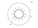
図14は、実施の形態5に係る照明装置140の主要部の配置を示す模式的部分断面図である。図15は、実施の形態5に係る照明装置140の点灯状態の説明図である。実施
の形態5に係る照明装置140においては、センタカバー8bの材料を不透光性の樹脂製とし、センタカバー8bの周壁部に周方向に略等配をなして複数の格子穴85を設けている。その他の構成は、図12及び図13に示す実施の形態4と同様であるため、対応する構成部材に図12及び図13と同一の参照符号を付して、その構成の詳細な説明を省略する。
In the illumination device 130 according to Embodiment 4, the arrangement of the illumination module 3 and the nightlight module 35 is divided into the light source holding part 24 and the power supply cover 6 of the chassis 2. As a result, when the illumination module 3 is turned on during the main illumination that illuminates the living space brightly during a normal life time zone, the portion of the translucent cover 7 becomes bright as shown in FIG. On the other hand, when the nightlight module 35 is turned on during nightlight illumination to illuminate the feet lightly at night or the like, the light from the nightlight LED 37 passes through the center cover 8a as shown in FIG. As shown, the center cover 8a is brightened. Thus, the light emission part can be changed in the case of main illumination and nightlight illumination.
(Embodiment 5)
FIG. 14 is a schematic partial cross-sectional view showing the arrangement of main parts of lighting apparatus 140 according to Embodiment 5. FIG. 15 is an explanatory diagram of a lighting state of the illumination device 140 according to Embodiment 5. In the illuminating device 140 according to Embodiment 5, the material of the center cover 8b is made of a non-translucent resin, and a plurality of lattice holes 85 are provided in the circumferential wall portion of the center cover 8b so as to be substantially evenly distributed in the circumferential direction. ing. Other configurations are the same as those of the fourth embodiment shown in FIGS. 12 and 13, and corresponding constituent members are denoted by the same reference numerals as in FIGS. 12 and 13, and detailed description of the configurations is omitted. To do.

実施の形態5に係る照明装置140は、センタカバー8bに格子穴85を設けて、図14及び図15に示すように、格子穴85から常夜灯モジュール35の常夜灯LED37からの光が出射するようにしてある。この結果、照明装置140の主照明の光出射方向ではく、主照明の照明モジュール3の光出射方向に略直交する方向、側方に常夜灯モジュール35からの光が出射することになる。例えば、照明装置140を天井に設置した場合、常夜灯LED37の光により、天井及び壁が照らされることなる。よって、常夜灯の光は柔らかい間接照明として提供することができる。また、センタカバー8bに格子穴85を設けているから、電源部41等により発生した熱を照明装置140の外部の空気に放散することが可能となる。   The illuminating device 140 according to Embodiment 5 is provided with a lattice hole 85 in the center cover 8b so that light from the nightlight LED 37 of the nightlight module 35 is emitted from the lattice hole 85 as shown in FIGS. It is. As a result, the light from the nightlight module 35 is emitted in a direction substantially perpendicular to the light emission direction of the illumination module 3 of the main illumination, not in the light emission direction of the main illumination of the illumination device 140. For example, when the lighting device 140 is installed on the ceiling, the ceiling and the wall are illuminated by the light of the nightlight LED 37. Therefore, the nightlight light can be provided as soft indirect illumination. In addition, since the lattice holes 85 are provided in the center cover 8b, it is possible to dissipate heat generated by the power supply unit 41 and the like to the air outside the lighting device 140.

なお、以上の実施の形態2乃至5に係る照明装置においては、常夜灯モジュール35の数を3つとしているが、3つに限定されず、1つでもよいし、2つまたは4以上であってもよい。即ち、使用者の好みに応じて選択されればよい。   In the lighting devices according to Embodiments 2 to 5, the number of nightlight modules 35 is three, but is not limited to three, and may be one, two, or four or more. Also good. That is, it may be selected according to the user's preference.

また、以上の実施の形態においては、電源カバー6を熱良導体の金属製としていたが、電源カバーの材料はこれに限定されず、透光性カバー7と同様に、透光性の樹脂製としてもよい。この場合、センタカバーも同様に、透光性の樹脂製とする。この結果、照明装置の中央部に新たにLEDを設けることなく、照明装置の中央部を光らせることが可能となる。また、センタカバーとして導光板を採用することにより、照明装置の中央付近を均一に発光させることが可能となる。この結果、照明装置の中央部が暗くなっていることによる違和感、不快感を使用者に与えずにすむ。   Further, in the above embodiment, the power supply cover 6 is made of a metal having a good thermal conductivity. However, the material of the power supply cover is not limited to this, and like the light-transmitting cover 7, it is made of a light-transmitting resin. Also good. In this case, the center cover is also made of a translucent resin. As a result, the central portion of the lighting device can be illuminated without newly providing an LED at the central portion of the lighting device. In addition, by employing a light guide plate as the center cover, it is possible to emit light uniformly around the center of the lighting device. As a result, it is possible to avoid giving the user a sense of discomfort and discomfort due to the dark central portion of the lighting device.

また、以上の実施の形態においては、透光性カバー7を一体形成しているが、これに限定されない。例えば、透光性カバーの環状部72は、乳白色の透光性の樹脂とし、側面部73及び背面部74は、透明な透光性の樹脂にする。これにより、被取付部材である天井を明るく照明することが可能となる。   Moreover, in the above embodiment, although the translucent cover 7 is integrally formed, it is not limited to this. For example, the annular portion 72 of the translucent cover is made of milky white translucent resin, and the side surface portion 73 and the back surface portion 74 are made of transparent translucent resin. Thereby, it becomes possible to illuminate the ceiling which is a member to be attached brightly.

また、以上の実施の形態においては、光源としてLEDを用いているが、これに限定されず、EL(Electro Luminescence)等を用いてもよい。   In the above embodiment, an LED is used as a light source. However, the present invention is not limited to this, and EL (Electro Luminescence) or the like may be used.

また、以上の実施の形態においては、天井等の被取付部材に設けられた引掛シーリングボディ等の被取付体に着脱可能に取付けられる照明装置を例に説明したが、これに限定されず、他のタイプの照明装置にも適用可能である。   Moreover, in the above embodiment, the illumination device that is detachably attached to the attached body such as the hooking ceiling body provided on the attached member such as the ceiling has been described as an example. This type of lighting device can also be applied.

さらに、本発明は、その他、特許請求の範囲に記載した事項の範囲内において種々変更した形態にて実施することが可能であることは言うまでもない。   Furthermore, it goes without saying that the present invention can be implemented in variously modified forms within the scope of the matters described in the claims.

1 アダプタ(取付部)
2 シャーシ(保持体)
3 照明モジュール(光源)
32 LED
4 電源基板
41 電源部
5 制御基板
6 電源カバー(カバー)
64 外周壁(仕切枠)
7 透光性カバー
1 Adapter (mounting part)
2 Chassis (holder)
3. Lighting module (light source)
32 LED
4 Power supply board 41 Power supply part 5 Control board 6 Power supply cover (cover)
64 Perimeter wall (partition frame)
7 Translucent cover

Claims (2)

シャーシと、The chassis,
LEDが実装された面が前面側に向けられ、裏面が前記シャーシの一面に設けられたLED基板と、An LED substrate in which the surface on which the LED is mounted is directed to the front side and the back side is provided on one surface of the chassis;
前記シャーシから離れた状態で前記シャーシに設けられ、前記LEDに電力を供給する電源部と、A power supply unit provided in the chassis in a state of being separated from the chassis, and supplying power to the LEDs;
前記シャーシに固定され、前記電源部を覆う電源カバーと、A power supply cover fixed to the chassis and covering the power supply unit;
を備えたことを特徴とする照明装置。An illumination device comprising:
前記電源カバーは、前記電源部の外側で前記シャーシに固定されていることを特徴とする請求項1に記載の照明装置。 The power supply cover, the illumination device according to claim 1, characterized in Rukoto outside of the power supply unit is fixed to the chassis.
JP2017018539A 2017-02-03 2017-02-03 Lighting device Active JP6200608B2 (en)

Priority Applications (1)

Application Number Priority Date Filing Date Title
JP2017018539A JP6200608B2 (en) 2017-02-03 2017-02-03 Lighting device

Applications Claiming Priority (1)

Application Number Priority Date Filing Date Title
JP2017018539A JP6200608B2 (en) 2017-02-03 2017-02-03 Lighting device

Related Parent Applications (1)

Application Number Title Priority Date Filing Date
JP2015123362A Division JP2015181130A (en) 2015-06-19 2015-06-19 Lighting device

Related Child Applications (3)

Application Number Title Priority Date Filing Date
JP2017068210A Division JP6225286B2 (en) 2017-03-30 2017-03-30 Lighting device
JP2017068211A Division JP6232156B2 (en) 2017-03-30 2017-03-30 Lighting device
JP2017068209A Division JP6225285B2 (en) 2017-03-30 2017-03-30 Lighting device

Publications (3)

Publication Number Publication Date
JP2017076634A JP2017076634A (en) 2017-04-20
JP2017076634A5 JP2017076634A5 (en) 2017-06-08
JP6200608B2 true JP6200608B2 (en) 2017-09-20

Family

ID=58549496

Family Applications (1)

Application Number Title Priority Date Filing Date
JP2017018539A Active JP6200608B2 (en) 2017-02-03 2017-02-03 Lighting device

Country Status (1)

Country Link
JP (1) JP6200608B2 (en)

Families Citing this family (1)

* Cited by examiner, † Cited by third party
Publication number Priority date Publication date Assignee Title
CN209325597U (en) * 2019-03-18 2019-08-30 欧普照明股份有限公司 Ceiling lamp and chassis

Family Cites Families (5)

* Cited by examiner, † Cited by third party
Publication number Priority date Publication date Assignee Title
JP2002270026A (en) * 2001-03-09 2002-09-20 Asahi Matsushita Electric Works Ltd Luminaire
JP4565307B2 (en) * 2001-09-12 2010-10-20 東芝ライテック株式会社 LED lighting device
US7614769B2 (en) * 2007-11-23 2009-11-10 Sell Timothy L LED conversion system for recessed lighting
JP5055200B2 (en) * 2008-05-09 2012-10-24 昭和電工株式会社 Lighting device, ceiling frame with lighting device and system ceiling
JP3154761U (en) * 2009-08-11 2009-10-22 王恵民 Environmental protection multifunctional LED lighting that can be repaired

Also Published As

Publication number Publication date
JP2017076634A (en) 2017-04-20

Similar Documents

Publication Publication Date Title
JP5306172B2 (en) Lighting device
JP5374662B2 (en) Lighting device
JP5495091B2 (en) lighting equipment
JP6225286B2 (en) Lighting device
JP6539859B2 (en) Translucent member and lighting apparatus provided with the same
JP2018010879A (en) Luminaire
JP5416858B2 (en) Lighting device
JP4636342B2 (en) lighting equipment
JP5918835B2 (en) Lighting device
JP2014130848A (en) Lighting device
JP5520411B2 (en) Lighting device
JP5521100B2 (en) Lighting device
JP6443697B2 (en) lighting equipment
JP6200608B2 (en) Lighting device
JP6232156B2 (en) Lighting device
JP2008204698A (en) Luminaire
JP6225285B2 (en) Lighting device
JP5520412B2 (en) Lighting device
JP6417609B2 (en) lighting equipment
JP2012146668A (en) Lighting fixture
JP2015181130A (en) Lighting device
JP5116865B2 (en) Lighting device
JP2013251141A (en) Light source unit and lighting fixture
JP2014053109A (en) Pendant type led lighting device
JP2012146441A (en) Lighting fixture

Legal Events

Date Code Title Description
A621 Written request for application examination

Free format text: JAPANESE INTERMEDIATE CODE: A621

Effective date: 20170203

A521 Written amendment

Free format text: JAPANESE INTERMEDIATE CODE: A523

Effective date: 20170411

A871 Explanation of circumstances concerning accelerated examination

Free format text: JAPANESE INTERMEDIATE CODE: A871

Effective date: 20170411

A975 Report on accelerated examination

Free format text: JAPANESE INTERMEDIATE CODE: A971005

Effective date: 20170608

A977 Report on retrieval

Free format text: JAPANESE INTERMEDIATE CODE: A971007

Effective date: 20170609

A131 Notification of reasons for refusal

Free format text: JAPANESE INTERMEDIATE CODE: A131

Effective date: 20170620

TRDD Decision of grant or rejection written
A01 Written decision to grant a patent or to grant a registration (utility model)

Free format text: JAPANESE INTERMEDIATE CODE: A01

Effective date: 20170822

A61 First payment of annual fees (during grant procedure)

Free format text: JAPANESE INTERMEDIATE CODE: A61

Effective date: 20170825

R150 Certificate of patent or registration of utility model

Ref document number: 6200608

Country of ref document: JP

Free format text: JAPANESE INTERMEDIATE CODE: R150