JP6200543B2 - Slot machine - Google Patents
Slot machine Download PDFInfo
- Publication number
- JP6200543B2 JP6200543B2 JP2016073913A JP2016073913A JP6200543B2 JP 6200543 B2 JP6200543 B2 JP 6200543B2 JP 2016073913 A JP2016073913 A JP 2016073913A JP 2016073913 A JP2016073913 A JP 2016073913A JP 6200543 B2 JP6200543 B2 JP 6200543B2
- Authority
- JP
- Japan
- Prior art keywords
- stop
- big bonus
- winning
- combination
- cherry
- Prior art date
- Legal status (The legal status is an assumption and is not a legal conclusion. Google has not performed a legal analysis and makes no representation as to the accuracy of the status listed.)
- Expired - Fee Related
Links
Images


Description
本発明は、各々が識別可能な複数種類の識別情報を変動表示可能な可変表示装置の表示結果に応じて所定の入賞が発生可能なスロットマシンに関する。 The present invention relates to a slot machine capable of generating a predetermined winning according to a display result of a variable display device capable of variably displaying a plurality of types of identification information each identifiable.
この種のスロットマシンには、特許文献1、2に記載のものが提案されている。
As this type of slot machine, those disclosed in
本発明は、このような問題点に着目してなされたものであり、遊技者から設定変更されたことが見抜かれてしまうことを防止できるスロットマシンを提供することを目的とする。 The present invention has been made paying attention to such problems, and an object of the present invention is to provide a slot machine that can prevent a player from forgetting that a setting has been changed .
上記課題を解決するために、本発明の請求項1に記載のスロットマシンは、
各々が識別可能な複数種類の識別情報を変動表示可能な可変表示部を備え、
前記可変表示部の変動表示を停止することで表示結果を導出し、該表示結果に応じて入賞が発生可能なスロットマシンにおいて、
前記可変表示部を変動表示させるために遊技者によって操作される開始操作手段と、
表示結果が導出される前に、遊技状態の移行を伴う特別入賞を含む入賞について発生を許容するか否かを決定する事前決定手段と、
前記特別入賞の発生を許容する旨が決定され、当該決定により許容された特別入賞を発生させることができなかったときに、当該決定を次ゲーム以降に持ち越す持越手段と、
前記スロットマシンへの電力供給が開始され、前記特別入賞の発生を許容する旨が決定されている場合に、前記特別入賞の発生を許容する旨が決定されていることを報知する特別報知手段と、
永久磁石が組み込まれたロータを囲むように配置された複数の励磁相に対して予め定められた順番で励磁することにより前記可変表示部を変動表示させるステッピングモータと、
前記ステッピングモータの前記複数の励磁相に対して予め定められた順番で励磁することにより前記可変表示部を変動表示させる変動制御を行うステッピングモータ制御手段と、
前記ステッピングモータが停止したときの励磁相に関する励磁相データを含む遊技の制御を行うためのデータを読み出し及び書き込み可能に記憶する記憶領域を有し、前記スロットマシンへの電力供給が停止しても該記憶領域に記憶されているデータを保持することが可能なデータ記憶手段と、
設定操作手段の操作に基づいて、遊技者にとっての有利度が異なる複数種類の設定値のうちから、いずれかの設定値を選択して設定する設定値設定手段と、
前記設定操作手段の操作に基づいて、前記設定値設定手段により新たな設定値が設定されるときに前記データ記憶手段に記憶されているデータを初期化する設定時初期化手段と、
を備え、
前記設定時初期化手段が初期化するデータには、前記励磁相データは含まれず、
前記設定時初期化手段により前記データ記憶手段の初期化が行われ、遊技者によって前記開始操作手段が操作されたときに、前記データ記憶手段に記憶されている前記励磁相データに基づいて前記変動制御を行う
ことを特徴としている。
In order to solve the above-described problem, a slot machine according to
A variable display unit capable of variably displaying a plurality of types of identification information each capable of being identified,
In the slot machine capable of deriving the display result by stopping the variable display of the variable display unit, and winning can be generated according to the display result,
Start operation means operated by a player to display the variable display unit in a variable manner;
A pre-determining means for deciding whether or not to allow a winning including a special winning with a transition of a gaming state before the display result is derived;
When it is determined that the occurrence of the special winning is permitted and the special winning permitted by the determination cannot be generated, a carry-over means for carrying over the determination after the next game;
Special notifying means for notifying that the generation of the special prize is determined when power supply to the slot machine is started and the generation of the special prize is determined to be permitted; ,
A stepping motor for variably displaying the variable display unit by exciting in a predetermined order with respect to a plurality of excitation phases arranged so as to surround a rotor incorporating a permanent magnet;
Stepping motor control means for performing variation control for variably displaying the variable display unit by exciting the plurality of excitation phases of the stepping motor in a predetermined order;
It has a storage area for storing data for performing game control including excitation phase data relating to the excitation phase when the stepping motor is stopped so as to be readable and writable, and even if power supply to the slot machine is stopped Data storage means capable of holding data stored in the storage area;
A setting value setting means for selecting and setting one of setting values from a plurality of types of setting values having different advantages for the player based on the operation of the setting operation means;
A setting time initialization means for initializing data stored in the data storage means when a new setting value is set by the setting value setting means based on an operation of the setting operation means;
Equipped with a,
The data initialized by the setting initialization means does not include the excitation phase data,
The data storage means is initialized by the setting time initialization means, and when the start operation means is operated by a player, the fluctuation is based on the excitation phase data stored in the data storage means. It is characterized by control.
本発明の手段1のスロットマシンは、
遊技用価値を用いて1ゲームに対して所定数の賭数を設定することによりゲームが開始可能となるとともに、各々が識別可能な複数種類の図柄を変動表示可能な可変表示装置(リール2L、2C、2R)に表示結果が導出表示されることにより1ゲームが終了し、該可変表示装置の表示結果に応じて入賞が発生可能とされたスロットマシン(スロットマシン1)であって、
ゲームを進行させる制御を行う遊技制御手段(メイン制御部41)を搭載した遊技制御基板(遊技制御基板40)と、
前記遊技制御基板(遊技制御基板40)を収容する基板ケース(基板ケース200)と、
取り出し規制部位(封止片231、211の接続片231a、211a)を破壊しない限り、前記基板ケース(基板ケース200)に収容された遊技制御基板(遊技制御基板40)を該基板ケース(基板ケース200)から取り出し不能とする取り出し規制手段(ワンウェイネジ)と、
前記取り出し規制部位(封止片231、211の接続片231a、211a)を被覆する取り出し規制部位被覆部材(被覆部材236)と、
被覆解除部位(被覆片236)を破壊しない限り、前記取り出し規制部位被覆部材(被覆部材236)による前記取り出し規制部位(封止片231、211の接続片231a、211a)の被覆を解除不能とする被覆解除規制手段(被覆部材236の嵌入部236c)と、
を備え、
前記遊技制御手段(メイン制御部41)は、
前記可変表示装置(リール2L、2C、2R)の表示結果が導出される前に、前記遊技用価値を用いることなくゲームを行うことが可能な複数種類の再遊技(リプレイゲーム)の付与を伴う再遊技入賞(リプレイ)を含む複数種類の入賞について発生を許容するか否かを決定する事前決定手段(内部抽選)と、
前記事前決定手段が前記再遊技入賞(リプレイ)の発生を許容する旨の決定を通常遊技状態よりも高い確率で行う第1の再遊技高確率状態(RT(1))及び第2の再遊技高確率状態(RT(2))に制御する再遊技高確率状態制御手段と、
を含み、
前記再遊技高確率状態制御手段は、前記通常遊技状態または前記第1の再遊技高確率状態(RT(1))において前記複数種類の再遊技入賞(再遊技役)のうち特定の再遊技入賞(リプレイ(2))が発生したときに前記第2の再遊技高確率状態(RT(2))に制御し、
前記事前決定手段は、前記第1の再遊技高確率状態(RT(1))において前記通常遊技状態よりも高い確率で前記特定の再遊技入賞(リプレイ(2))の発生を許容する旨を決定する
ことを特徴としている。
この特徴によれば、基板ケースから遊技制御基板を取り出す場合に破壊する必要のある取り出し規制部位が、取り出し規制部位被覆部材により被覆されるので、基板ケースから遊技制御基板を取り出すためには、取り出し規制部位被覆部材の被覆を解除したうえで、さらに取り出し規制部位を破壊する必要があり、基板ケースから遊技制御基板を取り出すことが一層困難となるため、遊技制御基板への不正を効果的に抑制できる。
また、取り出し規制部位被覆部材の被覆を解除するためには被覆解除部位を破壊しなければならず、これにより取り出し規制部位被覆部材の被覆を解除した後に再度取り出し規制部位被覆部材により取り出し規制部位を被覆させた状態を形成することが極めて困難となり、かつ、手間がかかるため、遊技制御基板への不正をより効果的に抑制することができる。
また、第1の再遊技高確率状態では、さらに第2の再遊技高確率状態への移行契機となる特定の再遊技入賞が発生する確率が高まるため、第1の再遊技高確率状態に制御されることによって第2の再遊技高確率状態に制御されることへの遊技者の期待感を高めることができる。すなわち第1の再遊技高確率状態に制御されるか否かによって第2の再遊技高確率状態に制御される確率が変化するため、ゲームの流れにメリハリをつけることができる。
The slot machine of
The game can be started by setting a predetermined number of bets for one game using the gaming value, and a variable display device (
A game control board (game control board 40) equipped with game control means (main control unit 41) for performing control to advance the game;
A board case (board case 200) for housing the game control board (game control board 40);
The game control board (game control board 40) accommodated in the board case (board case 200) is placed in the board case (board case) unless the take-out restricting portion (the
A take-out restricting portion covering member (covering member 236) covering the take-out restricting portion (the connecting
Unless the covering release part (covering piece 236) is destroyed, the covering of the removal restricting part (the connecting
With
The game control means (main control unit 41)
Before the display result of the variable display device (
A first re-playing high probability state (RT (1)) and a second re-playing state in which the pre-determining means makes a determination to allow the occurrence of the re-game winning (replay) with a higher probability than the normal gaming state. Re-probability high-probability state control means for controlling the high-probability state (RT (2));
Including
The re-game high probability state control means is configured to select a specific re-game prize among the plurality of types of re-game prizes (re-game players) in the normal game state or the first re-game high probability state (RT (1)). When (Replay (2)) occurs, control to the second replay high probability state (RT (2)),
The pre-determining means allows the occurrence of the specific replay winning (replay (2)) at a higher probability than the normal gaming state in the first replay high probability state (RT (1)). It is characterized by determining.
According to this feature, the take-out restricting part that needs to be destroyed when taking out the game control board from the board case is covered with the take-out restricting part covering member. It is necessary to remove the restriction part after removing the restriction part covering member, and it becomes more difficult to take out the game control board from the board case. it can.
In addition, in order to release the covering of the removal restricting portion covering member, the covering release portion must be destroyed, and after this, the removal restricting portion covering member is used again to release the removal restricting portion by the removal restricting portion covering member. Since it becomes extremely difficult to form the covered state and it takes time, fraud to the game control board can be more effectively suppressed.
Further, in the first replay high probability state, the probability of occurrence of a specific replay win that triggers the transition to the second replay high probability state is further increased, so the control is switched to the first replay high probability state. By doing so, the player's expectation to be controlled to the second replay high probability state can be enhanced. That is, the probability of being controlled to the second replay high probability state varies depending on whether or not the first replay high probability state is controlled, so that the game flow can be sharpened.
尚、所定数の賭数とは、少なくとも1以上の賭数であって、2以上の賭数が設定されることや最大賭数が設定されることでゲームが開始可能となるようにしても良い。また、複数の遊技状態に応じて定められた賭数が設定されることでゲームが開始可能となるようにしても良い。
また、前記第1の再遊技高確率状態は、例えば、予め定められた入賞が発生することや可変表示装置の表示結果が予め定められた表示結果となること、遊技者にとって有利な遊技状態の終了時などを契機に開始するものであれば良い。
また、前記第1の再遊技高確率状態において前記通常遊技状態よりも高い確率で前記特定の再遊技入賞の発生を許容する旨を決定するものであれば良く、通常遊技状態において特定の再遊技入賞の発生を許容する旨を決定しないものであっても良く、この場合には、第1の再遊技高確率状態に制御されることを条件に第2の再遊技高確率状態に制御されることとなる。
また、第2の再遊技高確率状態は、第1の再遊技高確率状態も遊技者にとって有利であること(例えば、第1の再遊技高確率状態よりも1ゲームあたりの遊技用価値の付与率が高い、または継続が期待できるゲーム数が第1の再遊技高確率状態よりも長いなど)が好ましく、このようにすることで、第1の再遊技高確率状態において第2の再遊技高確率状態に移行することへの期待感をさらに高めることができる。
Note that the predetermined number of bets is at least one bet number, and a game can be started by setting a bet number of two or more or setting a maximum bet number. good. Further, the game may be started by setting a bet amount determined according to a plurality of game states.
The first replay high probability state may be, for example, that a predetermined winning occurs, a display result of the variable display device becomes a predetermined display result, or a gaming state advantageous to the player. It may be anything that starts at the end.
Further, it is only necessary to determine that the generation of the specific replay prize is permitted with a higher probability in the first replay high probability state than in the normal game state. It may not be determined that the winning is allowed. In this case, the second replay high probability state is controlled on condition that the first replay high probability state is controlled. It will be.
In addition, the second replay high probability state is advantageous to the player as compared with the first replay high probability state (for example, giving a game value per game to the first replay high probability state). It is preferable that the number of games having a high rate or expected to be continued is longer than the first replay high probability state), and in this way, the second replay high in the first replay high probability state A sense of expectation for shifting to the probability state can be further increased.
本発明の手段2のスロットマシンは、手段1に記載のスロットマシンであって、
取り外し規制部位(封止片232の接続片232a)を破壊しない限り、前記スロットマシンの本体(取付ベース250)に対する前記基板ケース(基板ケース200)の取り外しが不能となるように該スロットマシンの本体(取付ベース250)と該基板ケース(基板ケース200)とを連結する連結手段(ワンウェイネジ)を備える
ことを特徴としている。
この特徴によれば、スロットマシンの本体から基板ケースを取り外すためには取り外し規制部位を破壊しなければならず、これにより基板ケースを取り外した場合にその痕跡が残るため、基板ケースごと不正な基板が収容されたものに交換するような不正がなされた場合でも、かかる不正を早期に発見することができる。
また、上記構成に加えて、前記取り外し規制部位を被覆する取り出し規制部位被覆部材と、被覆解除部位を破壊しない限り、前記取り外し規制部位被覆部材による前記取り外し規制部位の被覆を解除不能とする取り外し規制部位被覆解除規制手段と、をさらに備えることが好ましく、このようにすることで、スロットマシンの本体から基板ケースを取り外す場合に破壊する必要のある取り外し規制部位が、取り外し規制部位被覆部材により被覆されるので、スロットマシンの本体から基板ケースを取り外すためには、取り外し規制部位被覆部材の被覆を解除したうえで、さらに取り外し規制部位を破壊する必要があり、スロットマシンの本体から基板ケースを取り外すことが一層困難となるため、基板ケースごと不正な基板が収容されたものに交換するといった不正を一層効果的に抑制できる。また、取り外し規制部位被覆部材の被覆を解除するためには被覆解除部位を破壊しなければならず、これにより取り外し規制部位被覆部材の被覆を解除した後に再度取り外し規制部位被覆部材により取り外し規制部位を被覆させた状態を形成することが極めて困難となり、かつ、手間がかかるため、基板ケースごと不正な基板が収容されたものに交換するといった不正をより一層効果的に抑制することができる。
また、前記取り出し規制手段と、前記連結手段と、が共通の手段で構成されていても良い。すなわち前記スロットマシンの本体に対する前記基板ケースの取り外しが不能となるように該スロットマシンの本体と該基板ケースとを連結することで、前記基板ケースに収容された遊技制御基板を該基板ケースから取り出し不能となる手段にて構成されていても良く、これにより、一度の行程で基板ケースに収容された遊技制御基板を取り出し不能とし、かつスロットマシン本体に対する基板ケースの取り外しを不能化できる。
さらにこの場合にも、前記取り外し規制部位を被覆する取り出し規制部位被覆部材と、被覆解除部位を破壊しない限り、前記取り外し規制部位被覆部材による前記取り外し規制部位の被覆を解除不能とする取り外し規制部位被覆解除規制手段と、をさらに備えることが好ましく、このようにすることで、スロットマシンの本体から基板ケースを取り外すか、基板ケースから遊技制御基板を取り出す場合に破壊する必要のある取り外し規制部位が、取り外し規制部位被覆部材により被覆されるので、スロットマシンの本体から基板ケースを取り外したり、基板ケースから遊技制御基板を取り出すためには、取り外し規制部位被覆部材の被覆を解除したうえで、さらに取り外し規制部位を破壊する必要があり、スロットマシンの本体から基板ケースを取り外したり、基板ケースから遊技制御基板を取り出すことが一層困難となるため、遊技制御基板への不正及び基板ケースごと不正な基板が収容されたものに交換するといった不正を一層効果的に抑制できる。また、取り外し規制部位被覆部材の被覆を解除するためには被覆解除部位を破壊しなければならず、これにより取り外し規制部位被覆部材の被覆を解除した後に再度取り外し規制部位被覆部材により取り外し規制部位を被覆させた状態を形成することが極めて困難となり、かつ、手間がかかるため、遊技制御基板への不正及び基板ケースごと不正な基板が収容されたものに交換するといった不正をより一層効果的に抑制することができる。
The slot machine according to
Unless the removal restricting portion (the connecting
According to this feature, in order to remove the board case from the main body of the slot machine, the removal restricting portion must be destroyed, and when this is done, the trace remains when the board case is removed. Even if a fraud is done such as exchanging for something that is housed, such fraud can be detected early.
Further, in addition to the above configuration, the removal restriction part covering member that covers the removal restriction part and the removal restriction that makes it impossible to release the covering of the removal restriction part by the removal restriction part covering member unless the covering release part is destroyed. It is preferable to further include a part covering release restricting means, and in this way, the removal restricting part that needs to be destroyed when the substrate case is removed from the main body of the slot machine is covered with the removal restricting part covering member. Therefore, in order to remove the board case from the main body of the slot machine, it is necessary to release the covering of the removal restricting part covering member and to destroy the removal restricting part, and to remove the board case from the main body of the slot machine. In which an illegal board is contained in each board case. Unauthorized such replacement can be more effectively suppressed. Further, in order to release the covering of the removal restricting part covering member, the covering releasing part must be destroyed, and after this, the covering of the removal restricting part covering member is released, and then the removal restricting part covering member is again removed by the removal restricting part covering member. Since it becomes extremely difficult to form the covered state and it takes time and effort, it is possible to more effectively suppress fraud such as exchanging an entire board case with one containing an illegal board.
Further, the take-out restricting means and the connecting means may be constituted by a common means. That is, by connecting the main body of the slot machine and the board case so that the board case cannot be removed from the main body of the slot machine, the game control board accommodated in the board case is taken out from the board case. The game control board accommodated in the board case cannot be taken out in a single process, and the board case can be removed from the slot machine body.
Further in this case, the removal restricting portion covering member that covers the removal restricting portion and the removal restricting portion covering that makes it impossible to release the covering of the removal restricting portion by the removal restricting portion covering member unless the covering release portion is destroyed. It is preferable to further include a release restricting means, and in this way, a removal restricting portion that needs to be destroyed when removing the board case from the main body of the slot machine or taking out the game control board from the board case, Since it is covered by the removal restricting part covering member, in order to remove the board case from the main body of the slot machine or take out the game control board from the board case, the removal restricting part covering member is uncovered and the removal restriction is further controlled. The parts need to be destroyed, Since it is more difficult to remove the game control board and to remove the game control board from the board case, it is possible to more effectively suppress the illegal use of the game control board and the replacement of the board case with one containing an illegal board. . Further, in order to release the covering of the removal restricting part covering member, the covering releasing part must be destroyed, and after this, the covering of the removal restricting part covering member is released, and then the removal restricting part covering member is again removed by the removal restricting part covering member. Since it is extremely difficult and time-consuming to form a covered state, it is possible to further effectively prevent fraud to the game control board and replacement of the board case with an illegal board contained in the board case. can do.
本発明の手段3のスロットマシンは、手段1または2に記載のスロットマシンであって、
前記遊技制御基板(遊技制御基板40)は、該遊技制御基板に形成された配線パターンに電気的に接続する基板側コネクタ(基板側コネクタ620a)を有し、
前記スロットマシンは、
ゲームの進行に関わる信号を出力する第1の電子部品と遊技の進行に関わる信号が入力される第2の電子部品とのうち少なくとも一方を含む遊技用電子部品(投入メダルセンサ31)と、
前記基板側コネクタ(基板側コネクタ620a)に接続されるケーブル側コネクタ(ケーブル側コネクタ610a)を有し、前記遊技用電子部品(投入メダルセンサ31)と前記遊技制御基板(遊技制御基板40)との間における配線を構成する接続ケーブル(ケーブル600a)と、
接続解除部位(接続片522a)を破壊しない限り、前記遊技制御基板(遊技制御基板40)の前記基板側コネクタ(基板側コネクタ620a)と前記ケーブル側コネクタ(ケーブル側コネクタ610a)との接続を解除不能とする接続解除規制部材(コネクタカバー520)と、
を備える
ことを特徴としている。
この特徴によれば、ケーブル側コネクタを不正な打ち込み器具等のコネクタに差し替えて接続し、遊技制御基板に遊技の進行に関わる不正な信号を入出力させるといった不正行為を行うことが困難となるため、不正な打ち込み器具を使用して遊技者にとって有利な状態に設定したスロットマシンを、例えば遊技店の営業開始時等において遊技客に提供するといった不正営業の実施等を効果的に防止できる。また、接続解除規制部位の破壊という痕跡を残さなければケーブル側コネクタをケーブル側コネクタから分離することができない状態となるので、痕跡を残さずに打ち込み器具などの不正器具を接続することができなくなる。
The slot machine of
The game control board (game control board 40) has a board side connector (
The slot machine is
A gaming electronic component (inserted medal sensor 31) including at least one of a first electronic component that outputs a signal related to the progress of the game and a second electronic component that receives a signal related to the progress of the game;
A cable-side connector (cable-
The connection between the board-side connector (board-
It is characterized by having.
According to this feature, it is difficult to perform an illegal act such as replacing the cable side connector with a connector such as an unauthorized driving tool and causing the game control board to input / output an illegal signal related to the progress of the game. In addition, it is possible to effectively prevent the implementation of illegal sales such as providing a slot machine set in an advantageous state for a player using an illegal driving tool to a player at the start of business at a game store, for example. In addition, since the cable-side connector cannot be separated from the cable-side connector without leaving a trace of destruction of the connection restriction part, it is not possible to connect an unauthorized instrument such as a driving instrument without leaving a trace. .
本発明の手段4のスロットマシンは、手段1〜3のいずれかに記載のスロットマシンであって、
ゲームの進行上で使用する報知手段(液晶表示器51など)を備え、
前記遊技制御手段は、
前記事前決定手段により遊技者にとって有利な特別遊技状態(ボーナス)への移行を伴う特別入賞(特別役)の発生を許容する旨が決定され、該特別入賞(特別役)が発生しなかったときに、当該特別入賞の発生を許容する旨の決定(特別役の当選フラグ)を次ゲーム以降に持ち越す持越手段と、
前記特別入賞(特別役)の発生を許容する旨が決定されている旨を示す特別決定情報(特別役の当選フラグ)を含む、前記遊技制御手段(メイン制御部41)を構成するマイクロコンピュータ(CPU41a)が動作を行うためのデータを読み出し及び書き込み可能に記憶する記憶領域を有し、前記スロットマシンへの電力供給が停止しても該記憶領域に記憶されているデータを保持することが可能なデータ記憶手段(RAM41c)と、
前記遊技制御手段(メイン制御部41)の起動時に、前記データ記憶手段(RAM41c)に記憶されているデータに基づいて該遊技制御手段(メイン制御部41)の制御状態を復帰させる遊技制御状態復帰処理を実行する遊技制御状態復帰処理手段と、
前記遊技制御状態復帰処理手段によって前記遊技制御手段(メイン制御部41)の制御状態を復帰させる際に、前記特別決定情報(特別役の当選フラグ)が記憶されているか否かを判定する特別決定情報判定手段と、
前記特別決定情報判定手段が前記特別決定情報(特別役の当選フラグ)が記憶されていると判定した場合に、前記特別入賞(特別役)の発生が許容されている旨を前記報知手段(液晶表示器51など)にて報知させる報知制御を行う起動時報知制御手段と、
を含む
ことを特徴としている。
この特徴によれば、打ち込み器具などの不正器具を接続するには、一度電源を切る必要がある(電源を切らずにコネクタを外すと故障の原因となる)が、コネクタの接続を解除して打ち込み器具を使用し、不正に特別入賞の当選を設定しても、遊技制御手段を再起動させた際に、特別入賞に当選していることが外部から容易に判別できてしまうので、打ち込み器具を使用して特別入賞が当選した状態に設定したスロットマシンを、遊技店の営業開始時等において遊技客に提供するといった不正営業を効果的に防止することができる。
また、起動時に特別入賞の発生を許容する旨が決定されている状態で復帰する場合には、ゲームの進行上で使用する報知手段で特別入賞の発生が許容されている旨が報知されるので、報知手段がない状態で営業を開始することは困難であり、報知手段を取り外して報知させないようにするといった細工をすることを防止できるため、遊技店による不正営業を一層確実に防止することができる。
尚、遊技制御手段の起動時とは、電源投入に伴う起動時や、遊技制御手段の不具合に伴う再起動時などが該当する。
また、ゲームの進行上で使用する報知手段とは、ゲームの状況やクレジットの記憶数などを報知する表示器や告知用のランプ、演出用の表示装置、ランプなどが該当する。
また、前記起動時報知制御手段が、前記特別入賞の発生が許容されている旨を前記放置手段にて報知させる報知制御を行うとは、遊技制御手段が報知手段を直接制御して前記特別入賞の発生が許容されている旨を報知させるものであっても良いし、例えば遊技制御手段とは別個に演出の制御を行う演出制御手段を設け、遊技制御手段が演出制御手段に対して前記特別入賞の発生が許容されている旨の報知を指示し、報知手段を間接的に制御して前記特別入賞の発生が許容されている旨を報知させるものであっても良い。
The slot machine of
Provide notification means (such as the liquid crystal display 51) used in the progress of the game,
The game control means includes
The pre-determining means determines that it is allowed to generate a special prize (special role) accompanied by a transition to a special gaming state (bonus) advantageous to the player, and the special prize (special role) has not occurred. Sometimes carry-over means to carry over the decision to allow the occurrence of the special winning (special role winning flag) after the next game,
A microcomputer constituting the game control means (main control unit 41) including special decision information (special role winning flag) indicating that it is determined to allow the occurrence of the special prize (special role) The
Game control state return for returning the control state of the game control means (main control unit 41) based on the data stored in the data storage means (
Special decision for determining whether or not the special decision information (special role winning flag) is stored when the game control state return processing means returns the control state of the game control means (main control unit 41). Information determination means;
When the special determination information determination means determines that the special determination information (winning flag for special role) is stored, the notifying means (liquid crystal) indicates that the occurrence of the special prize (special role) is permitted. A start-up notification control means for performing notification control to be notified by a
It is characterized by including.
According to this feature, it is necessary to turn off the power once to connect unauthorized tools such as driving tools (disconnecting the connector without turning off the power). Even if you use a driving tool and illegally set a special winning prize, when you restart the game control means, you can easily determine from the outside that you have won the special winning tool. It is possible to effectively prevent illegal sales such as providing a player with a slot machine set in a state where a special prize is won by using the game machine when the game shop starts business.
In addition, when returning in a state in which it is determined to allow the generation of a special prize at the time of activation, the notification means used in the progress of the game notifies that the occurrence of the special prize is allowed. Since it is difficult to start a business in the absence of notification means, and it is possible to prevent crafts such as removing the notification means so as not to notify, it is possible to more surely prevent illegal sales by amusement stores. it can.
Note that the time when the game control means is started corresponds to the time when the power is turned on or the time when the game control means is restarted due to a malfunction of the game control means.
The notification means used in the progress of the game corresponds to a display, a notification lamp, an effect display device, a lamp, and the like that notify the game status and the number of stored credits.
In addition, when the start-up notification control means performs notification control in which the leaving means notifies that the occurrence of the special prize is allowed, the game control means directly controls the notification means to control the special prize. For example, an effect control means for controlling the effect is provided separately from the game control means, and the game control means provides the special control to the effect control means. A notification that the occurrence of a winning is permitted may be instructed, and the notification means may be indirectly controlled to notify that the occurrence of the special winning is permitted.
本発明の手段5のスロットマシンは、手段1〜4のいずれかに記載のスロットマシンであって、
前記遊技制御手段(メイン制御部41)は、
前記遊技制御手段を構成するマイクロコンピュータ(CPU41a)が動作を行うためのデータを読み出し及び書き込み可能に記憶する記憶領域を有し、前記スロットマシンへの電力供給が停止しても該記憶領域に記憶されているデータを保持することが可能なデータ記憶手段(RAM41c)と、
前記遊技制御手段(メイン制御部41)の起動時に、前記データ記憶手段(RAM41c)に記憶されているデータに基づいて該遊技制御手段(メイン制御部41)の制御状態を復帰させる遊技制御状態復帰処理を実行する遊技制御状態復帰処理手段と、
を含み、
前記スロットマシンは、前記電力供給が停止している状態で前記遊技用電子部品(投入メダルセンサ31)と前記遊技制御基板(遊技制御基板40)との間における配線上のコネクタ同士での接続が解除された場合に、前記データ記憶手段(RAM41c)に保持されているデータを初期化させる(CPU41aは、起動時に断線監視用IC50に断線フラグが記憶されている場合にデータを初期化する)停電時データ初期化手段を更に備える
ことを特徴としている。
この特徴によれば、打ち込み器具などの不正器具を接続するには、遊技用電子部品と前記遊技制御基板との間における配線上のコネクタ同士の接続の解除が必要となるが、無理矢理コネクタの接続を解除して打ち込み器具を使用し、不正に大当たりの当選を設定しても、正規のコネクタと交換するためにコネクタの接続を解除することでデータ記憶手段のデータが初期化されてしまうので、打ち込み器具を使用して特別入賞が当選した状態に設定したスロットマシンを、遊技店の営業開始時等において遊技客に提供するといった不正営業を効果的に防止することができる。
尚、前記スロットマシンへの電力供給が停止している状態で前記遊技用電子部品と前記遊技制御基板との間における配線上のコネクタ同士での接続が解除された場合に、前記データ記憶手段に保持されているデータを初期化させる停電時データ初期化手段は、回路構造上、前記スロットマシンへの電力供給が停止している状態で前記遊技用電子部品と前記遊技制御基板との間における配線上のコネクタ同士での接続が解除された場合に前記データ記憶手段に保持されているデータが失われるものであっても良いし、前記スロットマシンへの電力供給が停止している状態で前記遊技用電子部品と前記遊技制御基板との間における配線上のコネクタ同士での接続が解除されたか否かを監視する監視手段を設けるとともに、接続が解除された場合にはその旨を記憶しておき、起動時に接続が解除された旨が記憶されている場合にデータ記憶手段に保持されているデータを制御的に初期化するものであっても良い。
また、前記遊技用電子部品と前記遊技制御基板との間における配線上のコネクタ同士での接続が解除された場合とは、前記遊技用電子部品と前記遊技制御基板との間における配線上のコネクタ同士での接続が機械的に解除された場合及び電気的に解除された場合のどちらでも良い。
The slot machine of
The game control means (main control unit 41)
The microcomputer (
Game control state return for returning the control state of the game control means (main control unit 41) based on the data stored in the data storage means (
Including
In the slot machine, when the power supply is stopped, the connectors on the wiring between the game electronic component (the inserted medal sensor 31) and the game control board (game control board 40) are connected to each other. When released, the data stored in the data storage means (
According to this feature, in order to connect an unauthorized device such as a driving device, it is necessary to release the connection between the connectors on the wiring between the game electronic component and the game control board. Even if you use the driving tool to cancel and set the winning jackpot illegally, the data in the data storage means will be initialized by releasing the connection of the connector in order to replace it with a regular connector, It is possible to effectively prevent illegal sales such as providing a gaming machine with a slot machine set in a state where a special prize is won by using a driving tool at the start of business at a game shop or the like.
In the state where the power supply to the slot machine is stopped, when the connection between the connectors on the wiring between the gaming electronic component and the gaming control board is released, the data storage means A power failure time data initialization means for initializing stored data is a wiring between the game electronic component and the game control board in a state where power supply to the slot machine is stopped due to a circuit structure. The data stored in the data storage means may be lost when the connection between the upper connectors is released, or the game is performed with the power supply to the slot machine stopped. A monitoring means for monitoring whether or not the connection between the connectors on the wiring between the electronic component for use and the game control board is released, and when the connection is released Is stored to that effect, or may be controlled to initialize the data that the connection is released is held in the data storage means when stored at startup.
Further, when the connection between the connectors on the wiring between the gaming electronic component and the game control board is released, the connector on the wiring between the gaming electronic component and the gaming control board Either the case where the connection between them is released mechanically or the case where they are released electrically may be used.
本発明の手段6のスロットマシンは、手段1〜5のいずれかに記載のスロットマシンであって、
外部出力信号を出力するための外部出力端子を備え、
前記遊技制御手段(メイン制御部41)は、前記スロットマシンにおいて発生した複数種類の異常(投入エラー、払出エラーなど)を検出する異常検出手段を含み、
前記スロットマシンは、前記異常検出手段により異常が検出されたことに基づいて、異常が発生した旨及び異常の種類を特定可能な異常信号(セキュリティー信号)を、異常の種類に関わらず同一の前記外部出力端子から出力させるための外部出力制御手段(パラレル・シリアル変換回路1002)を備える
ことを特徴としている。
この特徴によれば、種類の異なる異常信号は頻繁に出力される信号ではなく、このような信号に対して個々に外部出力端子を設ける必要は低く、必要以上に多くの端子を設ける必要がなくなる。
尚、外部出力制御手段は、遊技制御手段が含んでいても良いし、遊技制御手段とは別個に備えていても良い。
また、異常が発生した旨及び異常の種類を特定可能な異常信号を、異常の種類に関わらず同一の前記外部出力端子から出力させるとは、同一のコネクタにまとめられた端子ではなく、1つの信号線に対して割り当てられた1つの外部出力端子から異常が発生した旨及び異常の種類を特定可能な異常信号を出力させることである。
The slot machine of
It has an external output terminal for outputting an external output signal,
The game control means (main control unit 41) includes abnormality detection means for detecting a plurality of types of abnormalities (such as insertion errors and payout errors) that have occurred in the slot machine,
The slot machine has the same abnormality signal (security signal) that can identify the fact that an abnormality has occurred and the type of abnormality based on the abnormality being detected by the abnormality detecting means, regardless of the type of abnormality. An external output control means (parallel / serial conversion circuit 1002) for outputting from an external output terminal is provided.
According to this feature, abnormal signals of different types are not frequently output signals, and it is not necessary to provide external output terminals individually for such signals, and it is not necessary to provide more terminals than necessary. .
The external output control means may be included in the game control means, or may be provided separately from the game control means.
In addition, the fact that an abnormality signal indicating that an abnormality has occurred and the type of abnormality can be output from the same external output terminal regardless of the type of abnormality is not a single terminal integrated into the same connector. It is to output an abnormality signal that can specify the type of abnormality and that an abnormality has occurred from one external output terminal assigned to the signal line.
本発明の手段7のスロットマシンは、手段1〜6のいずれかに記載のスロットマシンであって、
前記遊技制御手段は、
前記事前決定手段により遊技者にとって有利な特別遊技状態(ボーナス)への移行を伴う特別入賞(特別役)の発生を許容する旨が決定され、該特別入賞(特別役)が発生しなかったときに、当該特別入賞の発生を許容する旨の決定(特別役の当選フラグ)を次ゲーム以降に持ち越す持越手段と、
前記第2の再遊技高確率状態(RT(2))が開始した後、消化したゲーム数が規定のゲーム数に到達したときに該第2の再遊技高確率状態(RT(2))を終了させる再遊技高確率状態終了手段と、
を含み、
前記再遊技高確率状態終了手段は、前記第2の再遊技高確率状態(RT(2))が開始した後、前記規定ゲーム数に到達する前に前記事前決定手段が前記特別入賞(特別役)の発生を許容する旨を決定した場合には、該第2の再遊技高確率状態(RT(2))を終了させず、該特別入賞(特別役)が発生したとき、または該特別入賞(特別役)が発生せずに前記規定ゲーム数に到達したときに当該第2の再遊技高確率状態(RT(2))を終了させる
ことを特徴としている。
この特徴によれば、遊技用価値の増加が期待できる第2の再遊技高確率状態が開始した後、規定ゲーム数に到達する前に特別入賞の発生を許容する旨が決定されても、該決定により許容された特別入賞が発生しなければ、当該決定をもって第2の再遊技高確率状態が終了することがなく、規定ゲーム数に到達するまで第2の再遊技高確率状態に継続して制御することが可能となるため、第2の再遊技高確率状態において特別入賞の発生を許容する旨が決定されても、該決定により許容された特別入賞が発生しなければ第2の再遊技高確率状態を規定ゲーム数に到達するまで消化することが可能となり、遊技者に対して損失感を与えてしまうことがない。
The slot machine of
The game control means includes
The pre-determining means determines that it is allowed to generate a special prize (special role) accompanied by a transition to a special gaming state (bonus) advantageous to the player, and the special prize (special role) has not occurred. Sometimes carry-over means to carry over the decision to allow the occurrence of the special winning (special role winning flag) after the next game,
After the second replay high probability state (RT (2)) starts, the second replay high probability state (RT (2)) is reached when the number of digested games reaches a specified number of games. Re-game high probability state termination means to be terminated;
Including
The re-playing high probability state ending means is arranged such that after the second re-playing high probability state (RT (2)) is started, the pre-determining means performs the special winning (special prize) before reaching the prescribed number of games. If it is determined that the occurrence of the winning combination is allowed, the second replay high probability state (RT (2)) is not terminated and the special winning (special winning combination) is generated or The second replay high probability state (RT (2)) is terminated when the prescribed number of games is reached without generating a prize (special role).
According to this feature, even if it is determined that the occurrence of a special prize is allowed before the prescribed number of games is reached after the second re-playing high probability state in which an increase in gaming value can be expected is started, If the special prize allowed by the decision does not occur, the second replay high probability state will not be terminated by the decision, and the second replay high probability state is continued until the prescribed number of games is reached. Since it is possible to control, even if it is determined that the special prize is allowed to be generated in the second replay high probability state, the second replay is performed if the permitted special prize does not occur. It is possible to digest the high probability state until the specified number of games is reached, and the player is not given a sense of loss.
本発明の実施例を以下に説明する。 Examples of the present invention will be described below.
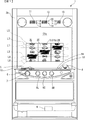
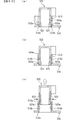
本発明が適用されたスロットマシンの実施例1を図面を用いて説明すると、本実施例のスロットマシン1は、前面が開口する筐体2aと、この筐体2aの側端に回動自在に枢支された前面扉2bと、から構成されている。
A slot machine according to a first embodiment to which the present invention is applied will be described with reference to the drawings. A
本実施例のスロットマシン1の筐体2aの内部には、図2に示すように、外周に複数種の図柄が配列されたリール2L、2C、2R(以下、左リール、中リール、右リールともいう)が水平方向に並設されており、図1に示すように、これらリール2L、2C、2Rに配列された図柄のうち連続する3つの図柄が前面扉2bに設けられた透視窓3から見えるように配置されている。
Inside the
リール2L、2C、2Rの外周部には、図3に示すように、それぞれ「赤7(図中黒7)」、「青7(図中網掛け7)」、「白7」、「リプレイ」、「スイカ」、「赤チェリー(図中黒チェリー)」、「青チェリー(図中網掛けチェリー)」、「ベル」、「オレンジ」といった互いに識別可能な複数種類の図柄が所定の順序で、それぞれ21個ずつ描かれている。リール2L、2C、2Rの外周部に描かれた図柄は、透視窓3において各々上中下三段に表示される。
As shown in FIG. 3, "red 7 (black 7 in the figure)", "blue 7 (shaded 7 in the figure)", "white 7", "replay" are provided on the outer peripheral portions of the
各リール2L、2C、2Rは、各々対応して設けられリールモータ32L、32C、32R(図4参照)によって回転させることで、各リール2L、2C、2Rの図柄が透視窓3に連続的に変化しつつ表示されるとともに、各リール2L、2C、2Rの回転を停止させることで、透視窓3に3つの連続する図柄が表示結果として導出表示されるようになっている。
The
前面扉2bの各リール2L、2C、2Rの手前側(遊技者側)の位置には、液晶表示器51(図1参照)の表示領域51aが配置されている。液晶表示器51は、液晶素子に対して電圧が印加されていない状態で、透過性を有するノーマリーホワイトタイプの液晶パネルを有しており、表示領域51aの透視窓3に対応する透過領域51b及び透視窓3を介して遊技者側から各リール2L、2C、2Rが視認できるようになっている。また、表示領域51aの透過領域51bを除く領域の裏面には、背後から表示領域51aを照射するバックライト(図示略)が設けられているとともに、さらにその裏面には、内部を隠蔽する隠蔽部材(図示略)が設けられている。
A
前面扉2bには、メダルを投入可能なメダル投入部4、メダルが払い出されるメダル払出口9、クレジット(遊技者所有の遊技用価値として記憶されているメダル数)を用いてメダル1枚分の賭数を設定する際に操作される1枚BETスイッチ5、クレジットを用いて、その範囲内において遊技状態に応じて定められた規定数の賭数のうち最大の賭数(本実施例では遊技状態に関わらず3)を設定する際に操作されるMAXBETスイッチ6、クレジットとして記憶されているメダル及び賭数の設定に用いたメダルを精算する(クレジット及び賭数の設定に用いた分のメダルを返却させる)際に操作される精算スイッチ10、ゲームを開始する際に操作されるスタートスイッチ7、リール2L、2C、2Rの回転を各々停止する際に操作されるストップスイッチ8L、8C、8R、既に行われた遊技の結果に関する遊技履歴データの閲覧や初期化、演出モードを選択する際に操作される選択スイッチ56及び決定スイッチ57、が遊技者により操作可能にそれぞれ設けられている。
On the
また、前面扉2bには、クレジットとして記憶されているメダル枚数が表示されるクレジット表示器11、後述するビッグボーナス中のメダルの獲得枚数やエラー発生時にその内容を示すエラーコード等が表示される遊技補助表示器12、入賞の発生により払い出されたメダル枚数が表示されるペイアウト表示器13が設けられている。
The
また、前面扉2bには、賭数が1設定されている旨を点灯により報知する1BETLED14、賭数が2設定されている旨を点灯により報知する2BETLED15、賭数が3設定されている旨を点灯により報知する3BETLED16、メダルの投入が可能な状態を点灯により報知する投入要求LED17、スタートスイッチ7の操作によるゲームのスタート操作が有効である旨を点灯により報知するスタート有効LED18、ウェイト(前回のゲーム開始から一定期間経過していないためにリールの回転開始を待機している状態)中である旨を点灯により報知するウェイト中LED19、後述するリプレイゲーム中である旨を点灯により報知するリプレイ中LED20が設けられている。
Further, on the
MAXBETスイッチ6の内部には、1枚BETスイッチ5、2枚BETスイッチ5b及びMAXBETスイッチ6の操作による賭数の設定操作が有効である旨を点灯により報知するBETスイッチ有効LED21(図4参照)が設けられており、ストップスイッチ8L、8C、8Rの内部には、該当するストップスイッチ8L、8C、8Rによるリールの停止操作が有効である旨を点灯により報知する左、中、右停止有効LED22L、22C、22R(図4参照)がそれぞれ設けられている。
Inside the
前面扉2bの内側には、所定のキー操作により後述するエラー状態及び後述する打止状態を解除するためのリセット操作を検出するリセットスイッチ23、後述する設定値の変更中や設定値の確認中にその時点の設定値が表示される設定値表示器24、メダル投入部4から投入されたメダルの流路を、筐体2a内部に設けられた後述のホッパータンク34a(図2参照)側またはメダル払出口9側のいずれか一方に選択的に切り替えるための流路切替ソレノイド30、メダル投入部4から投入され、ホッパータンク34a側に流下したメダルを検出する投入メダルセンサ31を有するメダルセレクタ(図示略)が設けられている。
Inside the
筐体2a内部には、図2に示すように、前述したリール2L、2C、2R、リールモータ32L、32C、32R、各リール2L、2C、2Rのリール基準位置をそれぞれ検出可能なリールセンサ33L、33C、33R(図4参照)からなるリールユニット2、外部出力信号を出力するための外部出力基板1000、メダル投入部4から投入されたメダルを貯留するホッパータンク34a、ホッパータンク34aに貯留されたメダルをメダル払出口9より払い出すためのホッパーモータ34b、ホッパーモータ34bの駆動により払い出されたメダルを検出する払出センサ34cからなるホッパーユニット34、電源ボックス100が設けられている。
As shown in FIG. 2, a
ホッパーユニット34の側部には、ホッパータンク34aから溢れたメダルが貯留されるオーバーフロータンク35が設けられている。オーバーフロータンク35の内部には、貯留された所定量のメダルを検出可能な高さに設けられた左右に離間する一対の導電部材からなる満タンセンサ35aが設けられており、導電部材がオーバーフロータンク35内に貯留されたメダルを介して接触することにより導電したときに内部に貯留されたメダル貯留量が所定量以上となったこと、すなわちオーバーフロータンクが満タン状態となったことを検出できるようになっている。
On the side of the
電源ボックス100の前面には、後述のビッグボーナス終了時に打止状態(リセット操作がなされるまでゲームの進行が規制される状態)に制御する打止機能の有効/無効を選択するための打止スイッチ36a、後述のビッグボーナス終了時に自動精算処理(クレジットとして記憶されているメダルを遊技者の操作によらず精算(返却)する処理)に制御する自動精算機能の有効/無効を選択するための自動精算スイッチ36b、起動時に設定変更モードに切り替えるための設定キースイッチ37、通常時においてはエラー状態や打止状態を解除するためのリセットスイッチとして機能し、設定変更モードにおいては後述する内部抽選の当選確率(出玉率)の設定値を変更するための設定スイッチとして機能するリセット/設定スイッチ38、電源をON/OFFする際に操作される電源スイッチ39が設けられている。
On the front surface of the
本実施例のスロットマシン1においてゲームを行う場合には、まず、メダルをメダル投入部4から投入するか、あるいはクレジットを使用して賭数を設定する。クレジットを使用するには1枚BETスイッチ5またはMAXBETスイッチ6を操作すれば良い。遊技状態に応じて定められた規定数の賭数が設定されると、入賞ラインL1〜L6(図1参照)が有効となり、スタートスイッチ7の操作が有効な状態、すなわち、ゲームが開始可能な状態となる。本実施例では、規定数の賭数として遊技状態に関わらず3枚が定められている。尚、遊技状態に対応する規定数のうち最大数を超えてメダルが投入された場合には、その分はクレジットに加算される。
When a game is played in the
入賞ラインとは、各リール2L、2C、2Rの透視窓3に表示された図柄の組合せが入賞図柄の組合せであるかを判定するために設定されるラインある。本実施例では、図1に示すように、各リール2L、2C、2Rの上段に並んだ図柄に跨って設定された入賞ラインL1、各リール2L、2C、2Rの下段に並んだ図柄に跨って設定された入賞ラインL2、リール2Lの下段、リール2Cの中段、リール2Rの上段、すなわち右上がりに並んだ図柄に跨って設定された入賞ラインL3、リール2Lの上段、リール2Cの中段、リール2Rの下段、すなわち右下がりに並んだ図柄に跨って設定された入賞ラインL4、リール2Lの下段、リール2Cの上段、リール2Rの中段に並んだ図柄に跨って設定された入賞ラインL5、リール2Lの上段、リール2Cの下段、リール2Rの中段に並んだ図柄に跨って設定された入賞ラインL6の6種類が入賞ラインとして定められている。
The winning line is a line that is set to determine whether the combination of symbols displayed on the
このように本実施例ではリール2L、2C、2Rの一直線上に位置する図柄に跨って設定される入賞ラインL1〜L4と、全てのリールにおいて上段・中段・下段のうち停止する位置が異なり、かつ一直線上に位置しない図柄に跨って入賞ラインL5、L6が設定されている。
As described above, in this embodiment, the winning lines L1 to L4 set across the symbols positioned on a straight line of the
尚、本実施例では、入賞ラインとして上述したL1〜L6を適用しているが、各リール2L、2C、2Rの中段に並んだ図柄に跨って設定される入賞ラインを加えて適用しても良い。また、上述したL5、L6のように一直線上に位置しない図柄に跨って設定される入賞ラインを適用しているが、一直線上に位置する図柄に跨って設定される入賞ラインのみを適用するようにしても良い。
In the present embodiment, the above-described L1 to L6 are applied as the pay lines. However, even if a pay line that is set across the symbols arranged in the middle stage of each
ゲームが開始可能な状態でスタートスイッチ7を操作すると、各リール2L、2C、2Rが回転し、各リール2L、2C、2Rの図柄が連続的に変動する。この状態でいずれかのストップスイッチ8L、8C、8Rを操作すると、対応するリール2L、2C、2Rの回転が停止し、透視窓3に表示結果が導出表示される。
When the
そして全てのリール2L、2C、2Rが停止されることで1ゲームが終了し、有効化されたいずれかの入賞ラインL1〜L6上に予め定められた図柄の組合せ(以下、役とも呼ぶ)が各リール2L、2C、2Rの表示結果として停止した場合には入賞が発生し、その入賞に応じて定められた枚数のメダルが遊技者に対して付与され、クレジットに加算される。また、クレジットが上限数(本実施例では50)に達した場合には、メダルが直接メダル払出口9(図1参照)から払い出されるようになっている。尚、有効化された複数の入賞ライン上にメダルの払出を伴う図柄の組合せが揃った場合には、有効化された入賞ラインに揃った図柄の組合せそれぞれに対して定められた払出枚数を合計し、合計した枚数のメダルが遊技者に対して付与されることとなる。ただし、1ゲームで付与されるメダルの払出枚数には、上限(本実施例では15枚)が定められており、合計した払出枚数が上限を超える場合には、上限枚数のメダルが付与されることとなる。また、有効化されたいずれかの入賞ラインL1〜L6上に、遊技状態の移行を伴う図柄の組合せが各リール2L、2C、2Rの表示結果として停止した場合には図柄の組合せに応じた遊技状態に移行するようになっている。
Then, when all the
図4は、スロットマシン1の構成を示すブロック図である。スロットマシン1には、図4に示すように、遊技制御基板40、演出制御基板90、電源基板101が設けられており、遊技制御基板40によって遊技状態が制御され、演出制御基板90によって遊技状態に応じた演出が制御され、電源基板101によってスロットマシン1を構成する電気部品の駆動電源が生成され、各部に供給される。
FIG. 4 is a block diagram showing a configuration of the
電源基板101には、外部からAC100Vの電源が供給されるとともに、このAC100Vの電源からスロットマシン1を構成する電気部品の駆動に必要な直流電圧が生成され、遊技制御基板40及び遊技制御基板40を介して接続された演出制御基板90に供給されるようになっている。
The
また、電源基板101には、前述したホッパーモータ34b、払出センサ34c、満タンセンサ35a、打止スイッチ36a、自動精算スイッチ36b、設定キースイッチ37、リセット/設定スイッチ38、電源スイッチ39に加え、前面扉2bの開放状態を検出するドア開放検出スイッチ25が接続されている。
In addition to the
遊技制御基板40には、前述した1枚BETスイッチ5、MAXBETスイッチ6、スタートスイッチ7、ストップスイッチ8L、8C、8R、精算スイッチ10、リセットスイッチ23、投入メダルセンサ31、リールセンサ33L、33C、33Rが接続されているとともに、電源基板101を介して前述した払出センサ34c、満タンセンサ35a、打止スイッチ36a、自動精算スイッチ36b、設定キースイッチ37、リセット/設定スイッチ38、ドア開放検出スイッチ25が接続されており、これら接続されたスイッチ類の検出信号が入力されるようになっている。
On the
また、遊技制御基板40には、前述したクレジット表示器11、遊技補助表示器12、ペイアウト表示器13、1〜3BETLED14〜16、投入要求LED17、スタート有効LED18、ウェイト中LED19、リプレイ中LED20、BETスイッチ有効LED21、左、中、右停止有効LED22L、22C、22R、設定値表示器24、流路切替ソレノイド30、リールモータ32L、32C、32Rが接続されているとともに、電源基板101を介して前述したホッパーモータ34bが接続されており、これら電気部品は、遊技制御基板40に搭載された後述のメイン制御部41の制御に基づいて駆動されるようになっている。
Further, the
遊技制御基板40には、CPU41a、ROM41b、RAM41c、I/Oポート41dを備えたマイクロコンピュータからなり、遊技の制御を行うメイン制御部41、所定範囲(本実施例では0〜16383)の乱数を発生させる乱数発生回路42、乱数発生回路から乱数を取得するサンプリング回路43、遊技制御基板40に直接または電源基板101を介して接続されたスイッチ類から入力された検出信号を検出するスイッチ検出回路44、リールモータ32L、32C、32Rの駆動制御を行うモータ駆動回路45、流路切替ソレノイド30の駆動制御を行うソレノイド駆動回路46、遊技制御基板40に接続された各種表示器やLEDの駆動制御を行うLED駆動回路47、スロットマシン1に供給される電源電圧を監視し、電圧低下を検出したときに、その旨を示す電圧低下信号をメイン制御部41に対して出力する電断検出回路48、電源投入時またはCPU41aからの初期化命令が入力されないときにCPU41aにリセット信号を与えるリセット回路49、遊技制御基板40と投入メダルセンサ31との間の電気的な接続状態及び遊技制御基板40と演出制御基板90との間の電気的な接続状態を監視する断線監視IC50、その他各種デバイス、回路が搭載されている。
The
CPU41aには、処理を実行するのに必要なデータの読み出し及び書き込みが行われる複数のレジスタ(記憶領域)が設けられている。詳しくは、主に演算用データが格納されるA、Fレジスタ(フラグレジスタ)、汎用データが格納されるB、C、D、E、H、Lレジスタ、実行中のプログラムの位置を示すデータが格納されるPCレジスタ、スタックポインタ(後述するスタック領域の現在の位置を示すアドレス)が格納されるSPレジスタ、後述するリフレッシュ動作を行うRAM41cのメモリブロックを示すデータが格納されるRレジスタ、RAM41cの格納領域を参照する際の基準となる位置を示すデータが格納されるIX、IYレジスタ、割込発生時に参照する割込テーブルの位置を示すデータが格納されるIレジスタが設けられている。
The
CPU41aは、計時機能、タイマ割込などの割込機能(割込禁止機能を含む)を備え、ROM41bに記憶されたプログラム(後述)を実行して、遊技の進行に関する処理を行うととともに、遊技制御基板40に搭載された制御回路の各部を直接的または間接的に制御する。ROM41bは、CPU41aが実行するプログラムや各種テーブル等の固定的なデータを記憶する。RAM41cは、CPU41aがプログラムを実行する際のワーク領域等として使用される。I/Oポート41dは、メイン制御部41が備える信号入出力端子を介して接続された各回路との間で制御信号を入出力する。
The
メイン制御部41は、信号入力端子DATAを備えており、遊技制御基板40に接続された各種スイッチ類の検出状態がこれら信号入力端子DATAを介して入力ポートに入力される。これら信号入力端子DATAの入力状態は、CPU41aにより監視されており、CPU41aは、信号入力端子DATAの入力状態、すなわち各種スイッチ類の検出状態に応じて段階的に移行する基本処理を実行する。
The
また、CPU41aは、前述のように割込機能を備えており、割込の発生により基本処理に割り込んで割込処理を実行できるようになっている。本実施例では、割込1〜4の4種類の割込を実行可能であり、各割込毎にカウンタモード(信号入力端子DATAとは別個に設けられたトリガー端子CLK/TRGからの信号入力に応じて外部割込を発生させる割込モード)とタイマモード(CPU41aのクロック入力数に応じて内部割込を発生させる割込モード)のいずれかを選択して設定できるようになっている。
In addition, the
本実施例では、割込1〜4のうち、割込2がカウンタモードに設定され、割込3がタイマモードに設定され、割込1、4は未使用とされている。トリガー端子CLK/TRGは、前述した電断検出回路48と接続されており、CPU41aは電断検出回路48から出力された電圧低下信号の入力に応じて割込2を発生させて後述する電断割込処理(メイン)を実行する。また、CPU41aは、クロック入力数が一定数に到達する毎、すなわち一定時間間隔(本実施例では、約0.56ms)毎に割込3を発生させて後述するタイマ割込処理(メイン)を実行する。また、割込1、4は、未使用に設定されているが、ノイズ等によって割込1、4が発生することがあり得る。このため、CPU41aは、割込1、4が発生した場合に、もとの処理に即時復帰させる未使用割込処理を実行するようになっている。
In the present embodiment, among the interrupts 1 to 4, interrupt 2 is set to the counter mode, interrupt 3 is set to the timer mode, and interrupts 1 and 4 are unused. The trigger terminal CLK / TRG is connected to the above-described power
また、CPU41aは、割込1〜4のいずれかの割込の発生に基づく割込処理の実行中に他の割込を禁止するように設定されているとともに、複数の割込が同時に発生した場合には、割込2、3、1、4の順番で優先して実行する割込が設定されている。すなわち割込2とその他の割込が同時に発生した場合には、割込2を優先して実行し、割込3と割込1または4が同時に発生した場合には、割込3を優先して実行するようになっている。
The
また、CPU41aは、割込1〜4のいずれかの割込の発生に基づく割込処理の開始時に、レジスタに格納されている使用中のデータをRAM41cに設けられた後述のスタック領域に一時的に退避させるとともに、当該割込処理の終了時にスタック領域に退避させたデータをレジスタに復帰させるようになっている。
Further, the
RAM41cには、DRAM(Dynamic RAM)が使用されており、記憶しているデータ内容を維持するためのリフレッシュ動作が必要となる。CPU41aには、このリフレッシュ動作を行うための前述したR(リフレッシュ)レジスタが設けられている。Rレジスタは、8ビットからなり、そのうちの下位7ビットが、CPU41aがROM41bから命令をフェッチする度に自動的にインクリメントされるもので、その値の更新は、1命令の実行時間毎に行われる。
As the
また、メイン制御部41には、停電時においてもバックアップ電源が供給されており、バックアップ電源が供給されている間は、CPU41aによりリフレッシュ動作が行われてRAM41cに記憶されているデータが保持されるようになっている。
The
また、CPU41aは、起動時において、打止スイッチ36a、自動精算スイッチ36bの状態を取得し、CPU41aの特定のレジスタに打止機能の有効/無効、自動精算機能の有効/無効を設定するようになっている。打止スイッチ36a及び自動精算スイッチ36bの状態は起動時においてのみ取得し、取得した状態に基づいて打止及び自動精算機能の有効/無効が設定されるため、その後に打止スイッチ36aや自動精算スイッチ36bが操作されても、新たに打止及び自動精算機能の有効/無効が設定されることはない。
Further, the
乱数発生回路42は、後述するように所定数のパルスを発生する度にカウントアップして値を更新するカウンタによって構成され、サンプリング回路43は、乱数発生回路42がカウントしている数値を取得する。乱数発生回路42は、乱数の種類毎にカウントする数値の範囲が定められており、本実施例では、その範囲として0〜16383が定められている。CPU41aは、その処理に応じてサンプリング回路43に指示を送ることで、乱数発生回路42が示している数値を乱数として取得する(以下、この機能をハードウェア乱数機能という)。後述する内部抽選用の乱数は、ハードウェア乱数機能により抽出した乱数をそのまま使用するのではなく、ソフトウェアにより加工して使用するが、その詳細については詳しく説明する。また、CPU41aは、前述のタイマ割込処理(メイン)により、特定のレジスタの数値を更新し、こうして更新された数値を乱数として取得する機能も有する(以下、この機能をソフトウェア乱数機能という)。
The random
断線監視IC50は、遊技制御基板40と投入メダルセンサ31との間の電気的な接続状態及び遊技制御基板40と演出制御基板90との間の電気的な接続状態を監視し、これらの接続状態の一方でも解除された場合には、これらの接続状態が解除された旨を示す断線フラグを断線監視IC50の内部に設けられたEEPROM(図示略)等の記憶部に記憶するようになっている。断線監視IC50は、CPU41aからの断線フラグの確認要求に応じて断線フラグが記憶されているか否かを返信し、この時点で断線フラグが記憶部に記憶されていればクリアする。
The
また、断線監視IC50にも停電時においてバックアップ電源が供給されるようになっており、例えば2〜3日間停電状態が継続しない限り、遊技制御基板40と投入メダルセンサ31との間の電気的な接続状態及び遊技制御基板40と演出制御基板90との間の電気的な接続状態の監視を継続できるようになっている。
The
CPU41aは、I/Oポート41dを介して演出制御基板90に、各種のコマンドを送信する。遊技制御基板40から演出制御基板90へ送信されるコマンドは一方向のみで送られ、演出制御基板90から遊技制御基板40へ向けてコマンドが送られることはない。遊技制御基板40から演出制御基板90へ送信されるコマンドの伝送ラインは、ストローブ(INT)信号ライン、データ伝送ライン、グラウンドラインから構成されているとともに、演出中継基板80を介して接続されており、遊技制御基板40と演出制御基板90とが直接接続されない構成とされている。
The
演出制御基板90には、前述した選択スイッチ56、決定スイッチ57が接続されており、これら接続されたスイッチ類の検出信号が入力されるようになっている。
The
演出制御基板90には、スロットマシン1の前面扉2bに配置された液晶表示器51(図1参照)、演出効果LED52、スピーカ53、54、リールLED55等の電気部品が接続されており、これら電気部品は、演出制御基板90に搭載された後述のサブ制御部91による制御に基づいて駆動されるようになっている。
The
演出制御基板90には、メイン制御部41と同様にCPU91a、ROM91b、RAM91c、I/Oポート91dを備えたマイクロコンピュータにて構成され、演出の制御を行うサブ制御部91、演出制御基板90に接続された液晶表示器51の表示制御を行う表示制御回路92、演出効果LED52、リールLED55の駆動制御を行うLED駆動回路93、スピーカ53、54からの音声出力制御を行う音声出力回路94、電源投入時またはCPU91aからの初期化命令が一定時間入力されないときにCPU91aにリセット信号を与えるリセット回路95、演出制御基板90に接続されたスイッチ類から入力された検出信号を検出するスイッチ検出回路96、日付情報及び時刻情報を含む時間情報を出力する時計装置97、スロットマシン1に供給される電源電圧を監視し、電圧低下を検出したときに、その旨を示す電圧低下信号をサブ制御部91に対して出力する電断検出回路98、その他の回路等、が搭載されており、CPU91aは、遊技制御基板40から送信されるコマンド、演出制御基板90に接続されたスイッチ類の検出を受けて、演出を行うための各種の制御を行うとともに、演出制御基板90に搭載された制御回路の各部を直接的または間接的に制御する。
Similar to the
CPU91aは、メイン制御部41のCPU41aと同様に、割込機能(割込禁止機能を含む)を備える。サブ制御部91の割込端子(図示略)は、コマンド伝送ラインのうち、メイン制御部41がコマンドを送信する際に出力するストローブ(INT)信号線に接続されており、CPU91aは、ストローブ信号の入力に基づいて割込を発生させて、メイン制御部41からのコマンドを取得し、バッファに格納するコマンド受信割込処理を実行する。また、CPU91aは、クロック入力数が一定数に到達する毎、すなわち一定間隔毎に割込を発生させて後述するタイマ割込処理(サブ)を実行する。
Similar to the
また、CPU91aの割込端子(図示略)は、前述した電断検出回路98と接続されており、CPU91aは電断検出回路98から出力された電圧低下信号の入力に応じて割込を発生させて後述する電断割込処理(サブ)を実行する。また、CPU91aにおいても未使用の割込が発生した場合には、もとの処理に即時復帰させる未使用割込処理を実行するようになっている。
The interrupt terminal (not shown) of the
また、CPU91aは、CPU41aとは異なり、ストローブ信号(INT)の入力に基づいて割込が発生した場合には、電断割込処理(サブ)を除く他の割込に基づく割込処理の実行中であっても、当該処理に割り込んでコマンド受信割込処理を実行し、電断割込処理(サブ)を除く他の割込が同時に発生してもコマンド受信割込処理を最優先で実行するようになっている。尚、電断割込処理(サブ)を除く割込処理の実行中は、ストローブ信号(INT)の入力に基づく割込以外の割込が禁止されるようになっている。これに対して電断割込処理(サブ)においては、コマンド受信割込処理を含む他の割込処理が一切禁止されており、さらに他の割込が同時に発生しても電断割込処理(サブ)を最優先で実行するようになっている。
Unlike the
また、サブ制御部91にも、停電時においてバックアップ電源が供給されており、バックアップ電源が供給されている間は、CPU91aによりリフレッシュ動作が行われてRAM91cに記憶されているデータが保持されるようになっている。
The
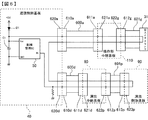
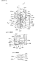
次に、遊技制御基板40と該遊技制御基板40に接続される各種遊技用電子部品との配線接続状態の詳細について、図5に基づいて説明する。尚、図5は、遊技制御基板40と該遊技制御基板40に接続される遊技用電子部品との配線接続状態を示す概略図である。
Next, details of wiring connection states between the
遊技制御基板40には、前述したように、1枚BETスイッチ5、MAXBETスイッチ6、スタートスイッチ7、ストップスイッチ8L、8C、8R、投入メダルセンサ31、リールモータ32L、32C、32R、リールセンサ33L、33C、33R、ホッパーモータ34b、払出センサ34c、演出制御基板90が接続されている。
As described above, on the
図5に示すように、これらのうち、1枚BETスイッチ5、MAXBETスイッチ6、スタートスイッチ7、ストップスイッチ8L、8C、8R、投入メダルセンサ31、リールモータ32L、32C、32R、リールセンサ33L、33C、33R、ホッパーモータ34b、払出センサ34cは、ゲームの進行に関わる信号を遊技制御基板40に入出力する電子部品である。ゲームの進行に関わる信号とは、例えば、ゲームを開始可能な状態とするための賭数の設定操作、ゲームを開始させるための操作、リール2L、2C、2Rの表示結果を導出させるための操作等、ゲームの進行操作に応じて遊技制御基板40に出力される信号や、投入メダルの検出、リールの基準位置の検出、払出メダルの検出等、ゲームの進行に応じて遊技用電子部品から出力されて遊技制御基板40に入力される信号と、スタート操作の検出に応じてリール2L、2C、2Rを駆動させるための駆動信号や、入賞の発生に伴いメダルを払い出すホッパーを駆動するための駆動信号等、ゲームの進行に応じて遊技制御基板40から出力されて遊技用電子部品に入力される信号と、を含む。
As shown in FIG. 5, among these, one
そして、これら遊技用電子部品は、ゲームの進行に応じて遊技制御基板40に信号を出力する第1の電子部品と、ゲームの進行に応じて遊技制御基板40からの信号が入力される第2の電子部品と、からなる。
These gaming electronic components are a first electronic component that outputs a signal to the
具体的には、賭数を設定する際に操作される1枚BETスイッチ5、MAXBETスイッチ6及び賭数を設定するために投入されたメダルを検出する投入メダルセンサ31は、該操作またはメダルの検出に基づいて遊技制御基板40にBET信号を出力する第1の電子部品である。メイン制御部41は、該BET信号の受信に基づいて賭数の設定処理を行うため、これら電子部品がないと賭数を設定することができない。すなわち、賭数を設定しないとゲームが開始可能な状態とならないため、1枚BETスイッチ5、MAXBETスイッチ6及び投入メダルセンサ31はゲームの進行に必要な遊技用電子部品である。
Specifically, the
ゲームを開始させるための操作を検出するスタートスイッチ7は、該操作の検出に基づいて遊技制御基板40にスタート信号を出力する第1の電子部品である。メイン制御部41は、該スタート信号の受信に基づいてゲームを開始する処理(リール回転処理等)を行うため、この電子部品がないとゲームを開始することができない。すなわち、スタートスイッチ7はゲームの進行に必要な遊技用電子部品である。
The
リール2L、2C、2Rの表示結果を導出させるための操作を検出するストップスイッチ8L、8C、8Rは、該操作の検出に基づいて遊技制御基板40にストップ信号を出力する第1の電子部品である。メイン制御部41は、該ストップ信号の受信に基づいて該当するリール2L、2C、2Rの回転を停止して表示結果を導出する処理を行うため、この電子部品がないとリール2L、2C、2Rの表示結果を導出することができない。すなわち、ストップスイッチ8L、8C、8Rはゲームの進行に必要な遊技用電子部品である。
Stop switches 8L, 8C, and 8R that detect an operation for deriving the display results of the
リール2L、2C、2Rの回転を検出するリールセンサ33L、33C、33Rは、リールの基準位置の検出信号を遊技制御基板40に出力する第1の電子部品である。メイン制御部41は、該リールの基準位置の検出信号の受信に基づいて該当するリール2L、2C、2Rの図柄の位置を把握して回転を停止する処理等を行うため、この電子部品がないと各リール2L、2C、2Rの表示結果の導出や入賞の判定等を行うことができない。すなわち、リールセンサ33L、33C、33Rはゲームの進行に必要な遊技用電子部品である。
The
入賞の発生に伴い払い出されるメダルを検出する払出センサ34cは、該メダルの検出に基づいて遊技制御基板40にメダル払出信号を出力する第1の電子部品である。メイン制御部41は、該払出メダル検出信号の受信に基づいて、発生した入賞に応じた枚数のメダルを払い出す払出処理を行うため、この電子部品がないと発生した入賞に応じた枚数のメダルを払い出すことができない。すなわち、払出センサ34cはゲームの進行に必要な遊技用電子部品である。
The
また、リール2L、2C、2Rを回転させるリールモータ32L、32C、32Rは、遊技制御基板40から出力される駆動信号が入力される第2の電子部品である。このリールモータ32L、32C、32Rは、遊技制御基板40から出力される駆動信号の入力に基づいてリール2L、2C、2Rを回転させて図柄の変動表示を開始するものであるが、該信号入力に基づいて実際にリール2L、2C、2Rを回転しなかったとしても、メイン制御部41は、リールの駆動信号を出力した後に上記リールセンサ33L、33C、33Rからの信号が入力されることで、リールが回転したとしてゲームを進行する制御を行うことができる。しかし、このリールセンサ33L、33C、33Rから信号が遊技制御基板40に入力されるタイミングは、リールの駆動信号の出力後でないとエラーとなるため、前述した打ち込み器具によりゲームを進行させる場合において、リールの回転の検出に基づく信号の出力タイミングを計るためにはリールの駆動信号が必要となる。すなわち、リールモータ32L、32C、32Rは、ゲームの進行に必要な遊技用電子部品である。
The
また、メダルの払い出しを行うホッパータンクを駆動するホッパーモータ34bは、入賞の発生に応じて遊技制御基板40から出力される駆動信号が入力される第2の電子部品である。このホッパーモータ34bは、遊技制御基板40から出力される駆動信号の入力に基づいてメダルの払出動作を行うものであるが、該信号入力に基づいて実際にメダルの払出動作を行わなかったとしても、メイン制御部41は、ホッパーモータ34bの駆動信号を出力した後に上記払出センサ34cからの信号が入力されることで、メダルが払い出されているとしてゲームを進行する制御を行うことができる。しかし、この払出センサ34cから信号が遊技制御基板40に入力されるタイミングは、ホッパーモータ34bの駆動信号の出力後でないとエラーとなるため、前述した打ち込み器具によりゲームを進行させる場合において、払出メダルの検出に基づく信号の出力タイミングを計るためには該ホッパーモータ34bの駆動信号が必要となる。すなわち、ホッパーモータ34bは、ゲームの進行に必要な遊技用電子部品である。
The
また、これら遊技用電子部品は、基本的には複数の機種に共通して継続使用される電子部品であり、故障等が発生しない限り本体から取り外して交換する機会は少ないので、スロットマシンの本体所定箇所に固設されている。これに対して遊技制御基板40や演出制御基板90等は、機種変更の際には交換が必要となるため、その際には本体から取り外される。つまり、遊技制御基板40を取り外す際には遊技用電子部品との接続を解除する必要があるため、遊技用電子部品と遊技制御基板40とは中継基板を経由して接続されているとともに、これら基板同士及び基板と遊技用電子部品とはケーブルを介して接続されている。またケーブルと基板とは、ケーブルの端部に設けられたケーブル側コネクタと基板の配線パターンと電気的に接続された基板側コネクタとの接続により電気的に接続されている。
These gaming electronic components are basically electronic components that are continuously used in common with multiple models, and there are few opportunities to remove them from the main unit unless a failure occurs. It is fixed in place. On the other hand, the
具体的に説明すると、1枚BETスイッチ5、MAXBETスイッチ6、スタートスイッチ7、ストップスイッチ8L、8C、8R、投入メダルセンサ31は、操作部中継基板110を経由して遊技制御基板40と配線接続され、リールモータ32L、32C、32R及びリールセンサ33L、33C、33Rは、リール中継基板120を経由して遊技制御基板40と配線接続され、ホッパーモータ34b及び払出センサ34cは、電源基板101を経由して遊技制御基板40と配線接続され、演出制御基板90は、演出中継基板80を経由して遊技制御基板40と配線接続されている。
More specifically, the
操作部中継基板110、リール中継基板120、電源基板101、演出制御基板90には、遊技制御基板40と各電子部品とを接続するための配線パターン(図示略)が設けられており、各電子部品から遊技制御基板40に対して出力される検出信号または遊技制御基板40から供給(入力)される電力や信号等を中継可能とされている。
The operation
また、このように各種電子部品と遊技制御基板40とを、スロットマシン1の本体(本実施例では、筐体2a)所定箇所に取り付けた各基板110、120、101、80を経由して配線接続することで、遊技制御基板40からスロットマシン1の本体所定箇所に個々に配設される複数の電子部品との配線の取りまとめが容易になるとともに、コネクタ接続部が常に中継基板または遊技制御基板40に設けられることになり、これにより各電子部品それぞれのコネクタ接続部が固定されるため、配線接続作業時においてコネクタ接続部を探したり、接続する配線の種類を間違うこと等が防止される。
In addition, various electronic components and the
遊技制御基板40と操作部中継基板110とは、ケーブル600aを介して接続され、遊技制御基板40とリール中継基板120とは、ケーブル600bを介して接続され、遊技制御基板40と電源基板101とは、ケーブル600cを介して接続されており、また、演出制御基板90と演出中継基板80とは、ケーブル600dを介して接続されている。
The
操作部中継基板110と1枚BETスイッチ5とはケーブル601aを介して接続され、操作部中継基板110とMAXBETスイッチ6とはケーブル601bを介して接続され、操作部中継基板110とスタートスイッチ7とはケーブル601cを介して接続され、操作部中継基板110とストップスイッチ8Lとはケーブル601dを介して接続され、操作部中継基板110とストップスイッチ8Cとはケーブル601eを介して接続され、操作部中継基板110とストップスイッチ8Rとはケーブル601fを介して接続され、操作部中継基板110と投入メダルセンサ31とはケーブル601gを介して接続されている。
The operation
また、リール中継基板120とリールモータ32Lとはケーブル601hを介して接続され、リール中継基板120とリールモータ32Cとはケーブル601jを介して接続され、リール中継基板120とリールモータ32Rとはケーブル601lを介して接続されている。また、リール中継基板120とリールセンサ33Lとはケーブル601iを介して接続され、リール中継基板120とリールセンサ33Cとはケーブル601kを介して接続され、リール中継基板120とリールセンサ33Lとはケーブル601mを介して接続されている。また、電源基板101とホッパーモータ34bとはケーブル601nを介して接続され、電源基板101と払出センサ34cとはケーブル601oを介して接続され、演出中継基板80と演出制御基板90とはケーブル601pを介して接続されている。
The
これら各ケーブル600a〜600c、601a〜601oは、各基板に対してコネクタ接続されており、基板との配線接続を解除可能となっている。具体的には、ケーブル600aの両端には、ケーブル側コネクタ610a、611aが設けられており、一方のケーブル側コネクタ610aは、遊技制御基板40に固設された基板側コネクタ620aに接続可能なコネクタであり、他方のケーブル側コネクタ611aは、操作部中継基板110に固設された基板側コネクタ621aに接続可能なコネクタである。ケーブル600bの両端には、ケーブル側コネクタ610b、611bが設けられており、一方のケーブル側コネクタ610bは、遊技制御基板40に固設された基板側コネクタ620bに接続可能なコネクタであり、他方のケーブル側コネクタ611bは、リール中継基板120に固設された基板側コネクタ621bに接続可能なコネクタである。ケーブル600cの両端には、ケーブル側コネクタ610c、611cが設けられており、一方のケーブル側コネクタ610cは、遊技制御基板40に固設された基板側コネクタ620cに接続可能なコネクタであり、他方のケーブル側コネクタ611cは、電源基板101に固設された基板側コネクタ621cに接続可能なコネクタである。ケーブル600dの両端には、ケーブル側コネクタ610d、611dが設けられており、一方のケーブル側コネクタ610dは、遊技制御基板40に固設された基板側コネクタ620dに接続可能なコネクタであり、他方のケーブル側コネクタ611dは、演出中継基板80に固設された基板側コネクタ621dに接続可能なコネクタである。
Each of these
また、一端が1枚BETスイッチ5に接続されたケーブル601aの他端には、操作部中継基板110に固設された基板側コネクタ622aに接続可能なケーブル側コネクタ612aが設けられている。一端がMAXBETスイッチ6に接続されたケーブル601bの他端には、操作部中継基板110に固設された基板側コネクタ622bに接続可能なケーブル側コネクタ612bが設けられている。一端がスタートスイッチ7に接続されたケーブル601cの他端には、操作部中継基板110に固設された基板側コネクタ622cに接続可能なケーブル側コネクタ612cが設けられている。一端がストップスイッチ8Lに接続されたケーブル601dの他端には、操作部中継基板110に固設された基板側コネクタ622dに接続可能なケーブル側コネクタ612dが設けられている。一端がストップスイッチ8Cに接続されたケーブル601eの他端には、操作部中継基板110に固設された基板側コネクタ622eに接続可能なケーブル側コネクタ612eが設けられている。一端がストップスイッチ8Rに接続されたケーブル601fの他端には、操作部中継基板110に固設された基板側コネクタ622fに接続可能なケーブル側コネクタ612fが設けられている。一端が投入メダルセンサ31に接続されたケーブル601gの他端には、操作部中継基板110に固設された基板側コネクタ622gに接続可能なケーブル側コネクタ612gが設けられている。
Further, a cable-
また、一端がリールモータ32Lに接続されたケーブル601hの他端及び一端がリールセンサ33Lに接続されたケーブル601iの他端には、リール中継基板120に固設された基板側コネクタ622hに接続可能なケーブル側コネクタ612hが設けられている。一端がリールモータ32Cに接続されたケーブル601jの他端及び一端がリールセンサ33Cに接続されたケーブル601kの他端には、リール中継基板120に固設された基板側コネクタ622iに接続可能なケーブル側コネクタ612iが設けられている。一端がリールモータ32Rに接続されたケーブル601lの他端及び一端がリールセンサ33Rに接続されたケーブル601mの他端には、リール中継基板120に固設された基板側コネクタ622jに接続可能なケーブル側コネクタ612jが設けられている。
Further, the other end of the
また、一端がホッパーモータ34bに接続されたケーブル601nの他端及び一端が払出センサ34cに接続されたケーブル601oの他端には、電源基板101に固設された基板側コネクタ622kに接続可能なケーブル側コネクタ612kが設けられている。
Further, the other end of the
また、ケーブル601pの両端には、ケーブル側コネクタ612p、613pが設けられており、一方のケーブル側コネクタ612pは、遊技制御基板40に固設された基板側コネクタ622pに接続可能なコネクタであり、他方のケーブル側コネクタ613pは、演出制御基板90に固設された基板側コネクタ623pに接続可能なコネクタである。
In addition, cable-
尚、本実施例では、各電子部品からはコネクタを介すことなく配線が延出されているが、コネクタを介して配線と接続されていても良い。 In this embodiment, the wiring is extended from each electronic component without using a connector, but may be connected to the wiring through a connector.
上述のように、各基板と各ケーブルとは、基板側に設けられる基板側コネクタ620a〜620d、621a〜621d、622a〜622k、622p、623pと、ケーブル側に設けられるケーブル側コネクタ610a〜610d、611a〜611d、612a〜612k、612p、613pとからなる一対のコネクタ(雄コネクタと雌コネクタ)を介して配線接続されており、基板側コネクタからケーブル側コネクタを抜脱することにより配線接続を解除することができるようになっている。特に、遊技制御基板40、操作部中継基板110、リール中継基板120、電源基板101、演出制御基板90は、スロットマシン1の筐体または前面扉の所定箇所に取り付けられていることで、基板側コネクタからケーブル側コネクタを抜脱しやすいので、遊技制御基板40や演出制御基板90の交換が容易に行うことができる。
As described above, each board and each cable includes board-
まず第1の電子部品に関して具体的に説明すると、1枚BETスイッチ5、MAXBETスイッチ6または投入メダルセンサ31と遊技制御基板40との間に設けられるケーブルのコネクタのうちいずれかのコネクタに打ち込み器具のコネクタが接続され、該打ち込み器具から遊技制御基板40にBET信号が不正に出力されると、賭数の設定操作が行われていないのに賭数が設定される虞がある。スタートスイッチ7と遊技制御基板40との間に設けられるケーブルのコネクタのうちいずれかのコネクタに打ち込み器具のコネクタが接続され、該打ち込み器具から遊技制御基板40にスタート信号が不正に出力されると、ゲームの開始操作を行うことなくゲームが開始される虞がある。ストップスイッチ8L、8C、8Rと遊技制御基板40との間に設けられるケーブルのコネクタのうちいずれかのコネクタに打ち込み器具のコネクタが接続され、該打ち込み器具から遊技制御基板40にストップ信号が不正に出力されると、停止操作を行うことなくリールの回転が停止される虞がある。リールセンサ33L、33C、33Rと遊技制御基板40との間に設けられるケーブルのコネクタのうちいずれかのコネクタに打ち込み器具のコネクタが接続され、該打ち込み器具から遊技制御基板40にリール回転信号が不正に出力されると、リールを回転させることなく各リール2L、2C、2Rの表示結果の導出や入賞の判定等が行われる虞がある。払出センサ34cと遊技制御基板40との間に設けられるケーブルのコネクタのうちいずれかのコネクタに打ち込み器具のコネクタが接続され、該打ち込み器具から遊技制御基板40にメダル払出信号が不正に出力されると、メダルを払い出すことなくメダルの計数が行われる虞がある。
First, the first electronic component will be described in detail. One of the
第2の電子部品に関して具体的に説明すると、リールモータ32L、32C、32Rと遊技制御基板40との間に設けられるケーブルのコネクタのうちいずれかのコネクタでの接続が解除されて遊技制御基板40から出力される駆動信号を打ち込み器具等で取得できることになると、リールの駆動信号が遊技制御基板40から出力されたタイミングを打ち込み器具側で特定できるので、本来リールセンサ33L、33C、33Rから遊技制御基板40に入力されるリール回転検出信号を、打ち込み器具からリール回転後の適正なタイミングで出力されてしまう虞がある。また、ホッパーモータ34bと遊技制御基板40との間に設けられるケーブルのコネクタのうちいずれかのコネクタでの接続が解除されて遊技制御基板40から出力される駆動信号を打ち込み器具等で取得できることになると、ホッパータンクの駆動信号が遊技制御基板40から出力されたタイミングを打ち込み器具側で特定できるので、本来払出センサ34cから遊技制御基板40に入力される払出メダル検出信号を、打ち込み器具からホッパータンクの駆動後の適正なタイミングで出力されてしまう虞がある。
The second electronic component will be described in detail. The
このように、ゲームの進行に応じて第1の電子部品から出力され、本来であれば遊技制御基板40に入力される信号が打ち込み器具から出力された場合、メイン制御部41は該信号の受信に基づいてゲームを進行する制御を行うことができるとともに、ゲームの進行に応じて遊技制御基板40から出力され、本来であれば第2の電子部品に入力される信号が打ち込み器具に入力された場合、打ち込み器具側では、メイン制御部41がリールモータやホッパーモータの駆動後に出力する信号の出力タイミング等を特定可能となり、これに基づいて新たな信号が遊技制御基板40に入力された場合には、メイン制御部41は該信号の受信に基づいてゲームを進行する制御を行うことができるので、ゲームを自動的に進行させるといった不正行為が実施される虞がある。よって、本実施例では、打ち込み器具の接続による不正行為を防止する種々の対策が施されている。尚、これらの対策については後に詳述する。
As described above, when a signal output from the first electronic component according to the progress of the game and originally input to the
次に、遊技制御基板40における断線監視IC50の周辺の構成を説明する。
Next, a configuration around the
遊技制御基板40には、電源基板101の電圧生成回路により生成された+5Vの直流電圧が供給される。電源基板101から供給された+5Vの直流電圧は、断線監視IC50の駆動電源として電源端子(VDD)に供給されるとともに、図6に示すように、遊技制御基板40上で分岐して遊技制御基板40と操作部中継基板110を配線接続するケーブル600a、操作部中継基板110、操作部中継基板110と投入メダルセンサ31を配線接続するケーブル601gを経由し、更に、投入メダルセンサ31で折り返して、ケーブル601g、操作部中継基板110、ケーブル600aを経由して遊技制御基板40に戻り、更に、遊技制御基板40と演出中継基板80を配線接続するケーブル600d、演出中継基板80、演出中継基板80と演出制御基板90を配線接続するケーブル601p、を経由し、更に、演出制御基板90で折り返して、ケーブル601p、演出中継基板80、ケーブル600dを経由して再度遊技制御基板40に戻り、断線監視IC50の入力端子(IN)に接続信号として入力されるようになっている。
The
このため、本実施例では、遊技制御基板40の基板側コネクタ620aとケーブル600aのケーブル側コネクタ610aとの接続、ケーブル600aのケーブル側コネクタ611aと操作部中継基板110の基板側コネクタ621aとの接続、操作部中継基板110の基板側コネクタ622gとケーブル601gのケーブル側コネクタ612gとの接続、遊技制御基板40の基板側コネクタ620dとケーブル600dのケーブル側コネクタ610dとの接続、ケーブル600dのケーブル側コネクタ611dと演出中継基板80の基板側コネクタ621dとの接続、演出中継基板80の基板側コネクタ622pとケーブル601pのケーブル側コネクタ612pとの接続、ケーブル601pのケーブル側コネクタ613pと演出制御基板90の基板側コネクタ623pとの接続、のいずれかの接続を解除することで、断線監視IC50の入力端子(IN)へ入力されている接続信号が遮断され、これにより断線監視IC50が遊技制御基板40と投入メダルセンサ31間及び遊技制御基板40と演出制御基板90間の断線を検出するようになっている。すなわち遊技制御基板40と投入メダルセンサ31の間のコネクタ同士の接続及び遊技制御基板40と演出制御基板90の間のコネクタ同士の接続が1カ所でも解除されると、断線監視IC50により断線が検出されるようになっている。
For this reason, in this embodiment, the board-
また、図6に示すように、電源基板101から供給された+5Vの直流電圧は、遊技制御基板40上で分岐して電源基板101側でグラウンドレベルに接続されるとともに、その間には大容量のコンデンサC1が設けられている。D1は逆流防止用のダイオードである。これにより+5Vの直流電圧をコンデンサC1に蓄積可能とされ、スロットマシン1に対する電力供給が遮断されたときに、コンデンサC1に蓄積された電圧を、断線監視IC50を駆動するためのバックアップ電源として供給できるようになっており、通電時であるか停電時であるかに関わらず断線監視IC50が遊技制御基板40と投入メダルセンサ31間及び遊技制御基板40と演出制御基板90間の断線を検出できるようになっている。
In addition, as shown in FIG. 6, the + 5V DC voltage supplied from the
本実施例のスロットマシン1は、遊技状態やエラーの発生状況などを示す外部出力信号を出力する。
The
これら外部出力信号は、図7(a)に示すように、CPU41aの制御により遊技制御基板40より出力され、外部出力基板1000、スロットマシン1が設置される遊技店(ホール)の情報提供端子板1010を介してホールコンピュータなどのホール機器に出力されるようになっている。
As shown in FIG. 7A, these external output signals are output from the
遊技制御基板40から外部出力基板1000に対しては、賭数の設定に用いられたメダル数を示すメダルIN信号、入賞の発生により遊技者に付与されたメダル数を示すメダルOUT信号、遊技状態が後述するレギュラーボーナス中の旨を示すRB中信号、遊技状態が後述するビッグボーナス中の旨を示すBB中信号、前面扉2bが開放中の旨を示すドア開放信号、後述する設定変更モードに移行している旨を示す設定変更信号、メダルセレクタの異常を示す投入エラー信号、ホッパーユニット34の異常を示す払出エラー信号がそれぞれ出力される。
From the
尚、本実施例では、チャレンジタイム(リールの滑りコマ数が制限されるものの、全ての小役について入賞が許容される遊技状態)や、チャレンジタイムが高確率となるチャレンジボーナスを搭載していないが、これらの遊技状態を搭載したスロットマシンとの共通化を図るため、遊技制御基板40と外部出力基板1000との間には、上記の信号を出力する信号線に加えて、遊技状態がチャレンジタイム中の旨を示すCT中信号、遊技状態がチャレンジボーナス中の旨を示すCB中信号を出力する信号線が接続されており、さらに将来拡張する可能性のあるエラー出力用の信号線が接続されている。
In this embodiment, there is no challenge time (a gaming state where the number of sliding pieces on the reel is limited, but winning is allowed for all small roles) and a challenge bonus with a high probability of challenge time. However, in order to make common with the slot machines equipped with these gaming states, in addition to the signal lines for outputting the above signals, the gaming state is a challenge between the
外部出力基板1000には、リレー回路1001、パラレル・シリアル変換回路1002、出力信号毎の端子が設けられ、情報提供端子板1010の回路と電気的に接続するための接続されるコネクタ1003が設けられている。
The
遊技制御基板40から出力された信号のうち、メダルIN信号、メダルOUT信号、RB中信号、BB中信号、(CT中信号、CB中信号)は、リレー回路1001を介して、そのままパルス信号として情報提供端子板1010に出力される。
Of the signals output from the
これに対してドア開放信号、設定変更信号、投入エラー信号、払出エラー信号、(予備信号)は、パラレル・シリアル変換回路1002にて、これらの信号を個別に識別可能なシリアル信号であるセキュリティ信号に変換して情報提供端子板1010に出力される。
On the other hand, a door opening signal, a setting change signal, a closing error signal, a payout error signal, and a (preliminary signal) are security signals that are serial signals that can be individually identified by the parallel /
これら外部出力基板1000から出力されたメダルIN信号、メダルOUT信号、RB中信号、BB中信号、(CT中信号、CB中信号)は、情報提供端子板1010を介してホール機器へ出力される。一方、外部出力基板1000から出力されたセキュリティ信号は、情報提供端子板1010にて再度、ドア開放信号、設定変更信号、投入エラー信号、払出エラー信号、予備信号に再変換されてホール機器へ出力されることとなる。
The medal IN signal, medal OUT signal, RB signal, BB signal, (CT signal, CB signal) output from the
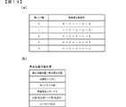
パラレル・シリアル変換回路1002は、ドア開放信号、設定変更信号、投入エラー信号、払出エラー信号、(予備信号)を、図7(b)に示すデータフォーマットにてシリアル信号に変換し、セキュリティ信号として出力する。基本フォーマットは、パルス幅20ms、フレーム長7ビットにて構成され、最初のビットがデータの開始を示すスタートビット、最後のビットがデータの終了を示すストップビット、その間のD1〜D5が送信データとなる。スタートビットは、1(on)、ストップビットは、0(off)となる。D1は、ドア開放信号の出力状態を示すビットであり、1(on)であればドア開放中信号on(前面扉2bの開放中)を示し、0(off)であればドア開放中信号offを示す。D2は、設定変更信号の出力状態を示すビットであり、1(on)であれば設定変更信号on(設定変更モードへ移行中)を示し、0(off)であれば設定変更信号offを示す。D3は、投入エラー信号の出力状態を示すビットであり、1(on)であれば投入エラー信号on(メダルセレクタに不正行為が行われた可能性が高い)を示し、0(off)であれば投入エラー信号offを示す。D4は、払出エラー信号の出力状態を示すビットであり、1(on)であれば払出エラー信号on(ホッパーユニット34に不正行為が行われた可能性が高い)を示し、0(off)であれば払出エラー信号offを示す。D5は、予備信号の出力状態を示すビットであり、本実施例では常に0となる。例えば、ドア開放信号がonでかつ設定変更信号がonであれば、図8(a)に示すように、スタートビット:1、D1:1、D2:1、D3:0、D4:0、D5:0、ストップビット:0となる。尚、この状態の後、設定変更信号がoffに変化した場合には、スタートビット:1、D1:1、D2:0、D3:0、D4:0、D5:0、ストップビット:0となる。
The parallel /
パラレル・シリアル変換回路1002は、ドア開放信号、設定変更信号、投入エラー信号、払出エラー信号、(予備信号)の出力状態に変化があった場合、すなわちいずれかの事象が発生した場合またはその事象が復旧した場合に、変化後の状態を示すフレームを3回繰り返して送信する。
The parallel /
図8(b)に示すように、スタートビットとスタートビットの間は、受信側で誤ラッチが生じないように、240msの間隔を空けるようになっている。すなわちストップビット後は、100msのブランクを空けて、次のフレームのスタートビットを送信するようになっている。 As shown in FIG. 8B, an interval of 240 ms is provided between the start bit and the start bit so as not to cause erroneous latching on the receiving side. That is, after the stop bit, a 100 ms blank is left and the start bit of the next frame is transmitted.
また、3回の反復送信を完了せずに、ドア開放信号、設定変更信号、投入エラー信号、払出エラー信号、(予備信号)の出力状態に変化があった場合には、図8(c)に示すように、変化後の出力状態を示すフレームを次回フレームより新たに3回反復送信する。この際、フレームの出力途中で、新たなフレームを送信したり、ストップビットの後、100msのブランクが経過していない状態で新たなフレームを送信したりすることがなく、出力中のフレーム送信後、100msのブランクを空けてから、新たなフレームを送信するようになっており、受信側でフレームの先頭を確実にラッチできるようになっている。 If the door open signal, the setting change signal, the input error signal, the payout error signal, and the (preliminary signal) output state are changed without completing the three repetitive transmissions, FIG. As shown in FIG. 5, a frame indicating the output state after the change is repeatedly transmitted three times from the next frame. At this time, there is no transmission of a new frame in the middle of frame output, or transmission of a new frame without a 100 ms blank after the stop bit. After a 100 ms blank, a new frame is transmitted, so that the reception side can reliably latch the head of the frame.
また、ドア開放信号、設定変更信号、投入エラー信号、払出エラー信号、(予備信号)のうち何らかの信号がonの状態から全ての信号がoffの状態に変化した場合には、スタートビットのみ1のフレームを3回送信するようになっている。 Also, when any signal among the door opening signal, setting change signal, closing error signal, payout error signal, and (preliminary signal) changes from the on state to the off state, only the start bit is set to 1. The frame is transmitted three times.
本実施例のスロットマシン1は、設定値に応じてメダルの払出率が変わるものであり、後述する内部抽選の当選確率は、設定値に応じて定まるものとなる。以下、設定値の変更操作について説明する。
In the
設定値を変更するためには、設定キースイッチ37をON状態としてからスロットマシン1の電源をONする必要がある。設定キースイッチ37をON状態として電源をONすると、設定値表示器24に設定値の初期値として1が表示され、リセット/設定スイッチ38の操作による設定値の変更操作が可能な設定変更モードに移行する。設定変更モードにおいて、リセット/設定スイッチ38が操作されると、設定値表示器24に表示された設定値が1ずつ更新されていく(設定6からさらに操作されたときは、設定1に戻る)。そして、スタートスイッチ7が操作されると設定値が確定し、確定した設定値がメイン制御部41のRAM41cに格納される。そして、設定キースイッチ37がOFFされると、遊技の進行が可能な状態に移行する。
In order to change the setting value, it is necessary to turn on the power of the
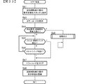
本実施例のスロットマシン1においては、メイン制御部41のCPU41aが電圧低下信号を検出した際に、電断割込処理(メイン)を実行する。電断割込処理(メイン)では、レジスタを後述するRAM41cのスタックに退避し、メイン制御部41のRAM41cにいずれかのビットが1となる破壊診断用データ(本実施例では、5AH)、すなわち0以外の特定のデータを格納するとともに、RAM41cの全ての領域に格納されたデータに基づくRAMパリティが0となるようにRAMパリティ調整用データを計算し、RAM41cに格納する処理を行うようになっている。尚、RAMパリティとはRAM41cの該当する領域(本実施例では、全ての領域)の各ビットに格納されている値の排他的論理和として算出される値である。このため、RAM41cの全ての領域に格納されたデータに基づくRAMパリティが0であれば、RAMパリティ調整用データは0となり、RAM41cの全ての領域に格納されたデータに基づくRAMパリティが1であれば、RAMパリティ調整用データは1となる。
In the
そして、CPU41aは、その起動時においてRAM41cの全ての領域に格納されたデータに基づいてRAMパリティを計算するとともに、破壊診断用データの値を確認し、RAMパリティが0であり、かつ破壊診断用データの値も正しいことを条件に、RAM41cに記憶されているデータに基づいてCPU41aの処理状態を電断前の状態に復帰させるが、RAMパリティが0でない場合(1の場合)や破壊診断用データの値が正しくない場合には、RAM異常と判定し、RAM異常エラーコードをレジスタにセットしてRAM異常エラー状態に制御し、遊技の進行を不能化させるようになっている。尚、RAM異常エラー状態は、他のエラー状態と異なり、リセットスイッチ23やリセット/設定スイッチ38を操作しても解除されないようになっており、前述した設定変更モードにおいて新たな設定値が設定されるまで解除されることがない。
The
また、CPU41aは、後述する内部抽選処理において設定された賭数が遊技状態に応じた賭数であるか否かを判定するとともに、内部抽選に用いる設定値が適正な値であるか否かを判定する。
Further, the
そして、設定された賭数が遊技状態に応じた賭数ではない場合、または内部抽選に用いる設定値が適正な値でない場合にも、RAM異常と判定し、RAM異常エラーコードをセットしてRAM異常エラー状態に制御し、遊技の進行を不能化させるようになっている。尚、前述のようにRAM異常エラー状態は、他のエラー状態と異なり、リセットスイッチ23やリセット/設定スイッチ38を操作しても解除されないようになっており、前述した設定変更モードにおいて新たな設定値が設定されるまで解除されることがない。
Even when the set bet number is not the bet number according to the gaming state, or when the set value used for the internal lottery is not an appropriate value, it is determined that the RAM is abnormal and the RAM abnormal error code is set and the RAM is set. The game is controlled to an abnormal error state and the progress of the game is disabled. As described above, unlike the other error states, the RAM abnormal error state is not canceled even if the
本実施例のスロットマシン1は、前述のように遊技状態に応じて設定可能な賭数の規定数が定められており、遊技状態に応じて定められた規定数の賭数が設定されたことを条件にゲームを開始させることが可能となる。本実施例では、後に説明するが、遊技状態として、レギュラーボーナス、通常遊技状態、RT(1)(リプレイタイム(1))、RT(2)(リプレイタイム(2))があるが、どの遊技状態においても賭数の規定数として3が定められている。このため、遊技状態がレギュラーボーナスであるか、通常遊技状態であるか、RT(1)であるか、RT(2)であるか、に関わらず、賭数として3が設定されるとゲームを開始させることが可能となる。尚、本実施例では、遊技状態に応じた規定数の賭数が設定された時点で、全ての入賞ラインL1〜L6が有効化されるようになっており、遊技状態に関わらず、賭数として3が設定された時点で全ての入賞ラインL1〜L6が有効化されることとなる。
In the
本実施例のスロットマシン1は、全てのリール2L、2C、2Rが停止した際に、有効化された入賞ライン(本実施例の場合、常に全ての入賞ラインが有効化されるため、以下では、有効化された入賞ラインを単に入賞ラインと呼ぶ)上に役と呼ばれる図柄の組合せが揃うと入賞となる。入賞となる役の種類は、遊技状態に応じて定められているが、大きく分けて、メダルの払い出しを伴う小役と、賭数の設定を必要とせずに次のゲームを開始可能となる再遊技役と、遊技状態の移行を伴う特別役と、がある。以下では、小役と再遊技役をまとめて一般役とも呼ぶ。遊技状態に応じて定められた各役の入賞が発生するためには、後述する内部抽選に当選して、当該役の当選フラグがRAM41cに設定されている必要がある。
In the
尚、これら各役の当選フラグのうち、小役及び再遊技役の当選フラグは、当該フラグが設定されたゲームにおいてのみ有効とされ、次のゲームでは無効となるが、特別役の当選フラグは、当該フラグにより許容された役の組合せが揃うまで有効とされ、許容された役の組合せが揃ったゲームにおいて無効となる。すなわち特別役の当選フラグが一度当選すると、例え、当該フラグにより許容された役の組合せを揃えることができなかった場合にも、その当選フラグは無効とされずに、次のゲームへ持ち越されることとなる。尚、特別役のうち後述するビッグボーナス(4)、ビッグボーナス(5)は当選したゲームにおいて必ず入賞することとなるため、次ゲーム以降に持ち越されることはない。 Of the winning flags for each of these combinations, the winning flag for the small role and the re-playing role is valid only in the game in which the flag is set, and is invalid in the next game. It is valid until a combination of combinations permitted by the flag is completed, and is invalid in a game having a combination of combinations permitted. In other words, once the special combination winning flag is won, even if the combination of the combinations permitted by the flag cannot be made, the winning flag is not invalidated and is carried over to the next game. It becomes. Of special bonuses, Big Bonus (4) and Big Bonus (5), which will be described later, are always won in the winning game, and are not carried over after the next game.
図9は、当選役テーブルを示す図である。当選役テーブルは、メイン制御部41のROM41bに予め格納されており、内部抽選において抽選対象となる役及び役の組合せに対応して、抽選が行われる順番に割り当てられた役番号(0〜22)が登録されている。
FIG. 9 shows a winning combination table. The winning combination table is stored in the
このスロットマシン1における役としては、特別役としてビッグボーナス(1)、ビッグボーナス(2)、ビッグボーナス(3)、ビッグボーナス(4)、ビッグボーナス(5)が、小役として赤チェリー、青チェリー、白チェリー、ベルが、再遊技役としてリプレイ(1)、リプレイ(2)が定められている。また、スロットマシン1における役の組合せとしては、ビッグボーナス(1)+赤チェリー、ビッグボーナス(2)+赤チェリー、ビッグボーナス(3)+赤チェリー、ビッグボーナス(1)+青チェリー、ビッグボーナス(2)+青チェリー、ビッグボーナス(3)+青チェリー、ビッグボーナス(1)+白チェリー、ビッグボーナス(2)+白チェリー、ビッグボーナス(3)+白チェリー、ベル+赤チェリー、ベル+青チェリー、ベル+白チェリーが定められている。すなわち、役及び役の組合せの合計は23となっている。
In the
本実施例のスロットマシン1においては、図9に示すように、遊技状態が、通常遊技状態、RT(1)またはRT(2)であるか、レギュラーボーナスであるかによって抽選の対象となる役及び役の組合せが異なる。特に遊技状態が通常遊技状態、RT(1)またはRT(2)である場合には、いずれかの特別役の持ち越し中か否か(特別役の当選フラグにいずれかの特別役が当選した旨が既に設定されているか否か)によっても抽選の対象となる役及び役の組合せが異なる。
In the
本実施例では、遊技状態に応じた状態番号が割り当てられており、内部抽選を行う際に、現在の遊技状態に応じた状態番号を設定し、この状態番号と賭数に応じて抽選対象となる役を特定することが可能となる。具体的には、通常遊技状態においていずれの特別役も持ち越されていない場合においては状態番号として「0」が設定され、RT(1)においていずれの特別役も持ち越されていない場合には、状態番号として「1」が設定され、RT(2)においていずれの特別役も持ち越されていない場合においては、状態番号として「2」が設定され、通常遊技状態においていずれかの特別役が持ち越されている場合においては、状態番号として「3」が設定され、RT(2)においていずれかの特別役が持ち越されている場合には、状態番号として「4」が設定され、レギュラーボーナスである場合には、状態番号として「5」が設定されるようになっている。尚、後述するが、RT(1)は特別役の当選で終了することとなるため、RT(1)において特別役が持ち越されることはない。 In this embodiment, a state number corresponding to the gaming state is assigned, and when performing an internal lottery, a state number corresponding to the current gaming state is set, and a lottery object is selected according to the state number and the number of bets. Can be identified. Specifically, when no special combination is carried over in the normal gaming state, “0” is set as the state number, and when no special combination is carried over at RT (1), the state is set. If “1” is set as the number and no special combination is carried over in RT (2), “2” is set as the state number and any special combination is carried over in the normal gaming state. If the status number is set to “3” and any special combination is carried over in RT (2), the status number is set to “4” and the bonus is a regular bonus. Is set to "5" as the state number. As will be described later, since RT (1) ends with the winning of the special role, the special role is not carried over in RT (1).
図9に示すように、遊技状態が通常遊技状態、RT(1)またはRT(2)であり、いずれの特別役も持ち越されていない状態、すなわち状態番号として「0」、「1」または「2」が設定されている場合には、ビッグボーナス(1)、ビッグボーナス(2)、ビッグボーナス(3)、ビッグボーナス(4)、ビッグボーナス(5)、ビッグボーナス(1)+赤チェリー、ビッグボーナス(2)+赤チェリー、ビッグボーナス(3)+赤チェリー、ビッグボーナス(1)+青チェリー、ビッグボーナス(2)+青チェリー、ビッグボーナス(3)+青チェリー、ビッグボーナス(1)+白チェリー、ビッグボーナス(2)+白チェリー、ビッグボーナス(3)+白チェリー、リプレイ(1)、リプレイ(2)、赤チェリー、青チェリー、白チェリー、ベル、すなわち役番号0〜19の役及び役の組合せが内部抽選の対象となる。
As shown in FIG. 9, the gaming state is the normal gaming state, RT (1) or RT (2), and no special role is carried over, that is, the state number is “0”, “1” or “ 2 ”is set, big bonus (1), big bonus (2), big bonus (3), big bonus (4), big bonus (5), big bonus (1) + red cherry, Big Bonus (2) + Red Cherry, Big Bonus (3) + Red Cherry, Big Bonus (1) + Blue Cherry, Big Bonus (2) + Blue Cherry, Big Bonus (3) + Blue Cherry, Big Bonus (1) + White Cherry, Big Bonus (2) + White Cherry, Big Bonus (3) + White Cherry, Replay (1), Replay (2), Red Cherry, Blue Cherry, White Chi Lee, Bell, that is a combination of winning and prize of winning
また、遊技状態が通常遊技状態またはRT(2)であり、いずれかの特別役が持ち越されている状態、すなわち状態番号として「3」または「4」が設定されている場合には、リプレイ(1)、リプレイ(2)、赤チェリー、青チェリー、白チェリー、ベル、すなわち役番号14〜19の役が内部抽選の対象となる。また、遊技状態がレギュラーボーナス、すなわち状態番号として「5」が設定されている場合には、ベル、ベル+赤チェリー、ベル+青チェリー、ベル+白チェリー、すなわち役番号19以降の役及び役の組合せが内部抽選の対象となる。
Further, when the gaming state is the normal gaming state or RT (2) and any special role is carried over, that is, when the state number is set to “3” or “4”, the replay ( 1), Replay (2), Red Cherry, Blue Cherry, White Cherry, Bell, that is, a combination of
赤チェリーは、いずれの遊技状態においても左リールについて入賞ラインのいずれかに「赤チェリー」の図柄が導出されたときに入賞となり、1枚のメダルが払い出される。青チェリーは、いずれの遊技状態においても左リールについて入賞ラインのいずれかに「青チェリー」の図柄が導出されたときに入賞となり、1枚のメダルが払い出される。白チェリーは、いずれの遊技状態においても左リールについて入賞ラインのいずれかに「白チェリー」の図柄が導出されたときに入賞となり、1枚のメダルが払い出される。尚、「赤チェリー」、「青チェリー」または「白チェリー」の図柄が左リールの上段または下段に停止した場合には、入賞ラインL1、L3、L5または入賞ラインL2、L4、Lの3本の入賞ラインに赤チェリー、青チェリーまたは白チェリーの組合せが揃うこととなり、3本の入賞ライン上で赤チェリー、青チェリーまたは白チェリーに入賞したこととなるので、3枚のメダルが払い出されることとなる。 The red cherry is awarded when a symbol “red cherry” is derived on any of the winning lines for the left reel in any gaming state, and one medal is paid out. The blue cherry is awarded when the symbol “blue cherry” is derived on any of the winning lines for the left reel in any gaming state, and one medal is paid out. The white cherry is awarded when a symbol of “white cherry” is derived on any of the winning lines for the left reel in any gaming state, and one medal is paid out. If the symbols “red cherry”, “blue cherry” or “white cherry” are stopped at the upper or lower stage of the left reel, three winning lines L1, L3, L5 or winning lines L2, L4, L A combination of red cherries, blue cherries or white cherries will be on the winning line, and red cherries, blue cherries or white cherries will be awarded on the three winning lines, so three medals will be paid out. It becomes.
ベルは、いずれの遊技状態においても入賞ラインのいずれかに「ベル−ベル−ベル」の組合せが揃ったときに入賞となり、15枚のメダルが払い出される。 The bell is awarded when a combination of “bell-bell-bell” is arranged on any of the winning lines in any gaming state, and 15 medals are paid out.
リプレイ(1)は、通常遊技状態、RT(1)及びRT(2)において入賞ラインのいずれかに「リプレイ−リプレイ−リプレイ」の組合せが揃ったときに入賞となる。(リプレイ(2)は、通常遊技状態、RT(1)及びRT(2)において入賞ラインのいずれかに「ベル−リプレイ−リプレイ」の組合せが揃ったときに入賞となる。リプレイ(1)またはリプレイ(2)が入賞したときには、メダルの払い出しはないが次のゲームを改めて賭数を設定することなく開始できるので、次のゲームで設定不要となった賭数に対応した3枚のメダルが払い出されるのと実質的には同じこととなる。 Replay (1) is awarded when the combination of “replay-replay-replay” is aligned on any of the winning lines in the normal gaming state, RT (1) and RT (2). (Replay (2) becomes a winning when the combination of “Bell-Replay-Replay” is arranged in any of the winning lines in the normal gaming state, RT (1) and RT (2). Replay (1) or When Replay (2) wins, there is no payout of medals, but the next game can be started without setting the number of bets again. This is essentially the same as being paid out.
ビッグボーナスは、通常遊技状態、RT(1)及びRT(2)において入賞ラインのいずれかに「赤7−赤7−赤7」の組合せ、「青7−青7−青7」、「白7−白7−白7」の組合せ、「ベル−リプレイ−ベル」の組合せ、「リプレイ−リプレイ−ベル」の組合せが揃ったときに入賞となる。本実施例において「赤7−赤7−赤7」の組合せが揃ったときに入賞となるビッグボーナスをビッグボーナス(1)とし、「青7−青7−青7」の組合せが揃ったときに入賞となるビッグボーナスをビッグボーナス(2)とし、「白7−白7−白7」の組合せが揃ったときに入賞となるビッグボーナスをビッグボーナス(3)とし、「ベル−リプレイ−ベル」の組合せが揃ったときに入賞となるビッグボーナスをビッグボーナス(4)とし、「リプレイ−リプレイ−ベル」の組合せが揃ったときに入賞となるビッグボーナスをビッグボーナス(5)とする。
The big bonus is a combination of “red 7-red 7-
ビッグボーナス(1)が入賞すると、遊技状態がビッグボーナス(1)に移行し、ビッグボーナス(2)が入賞すると、遊技状態がビッグボーナス(2)に移行し、ビッグボーナス(3)が入賞すると、遊技状態がビッグボーナス(3)に移行し、ビッグボーナス(4)が入賞すると、遊技状態がビッグボーナス(4)に移行し、ビッグボーナス(5)が入賞すると、遊技状態がビッグボーナス(5)に移行する。ビッグボーナス(1)〜(5)に移行すると、ビッグボーナス(1)〜(5)への移行と同時にレギュラーボーナスに移行する。レギュラーボーナスは、12ゲームを消化したとき、または8ゲーム入賞(役の種類は、いずれでも可)したとき、のいずれか早いほうで終了する。遊技状態がレギュラーボーナスにある間は、レギュラーボーナス中フラグがRAM41cに設定される。レギュラーボーナスが終了した際に、ビッグボーナス(1)〜(5)が終了していなければ、再度レギュラーボーナスに移行し、ビッグボーナス(1)〜(5)が終了するまで繰り返しレギュラーボーナスに制御される。すなわちビッグボーナス(1)〜(5)中は、常にレギュラーボーナスに制御されることとなる。
When the big bonus (1) wins, the gaming state shifts to the big bonus (1), and when the big bonus (2) wins, the gaming state shifts to the big bonus (2) and the big bonus (3) wins. When the gaming state shifts to the big bonus (3) and the big bonus (4) wins, the gaming state shifts to the big bonus (4) and when the big bonus (5) wins, the gaming state shifts to the big bonus (5 ). When shifting to the big bonus (1) to (5), the shift to the regular bonus is performed simultaneously with the shift to the big bonus (1) to (5). The regular bonus ends when 12 games are consumed, or when 8 games are won (any kind of combination is possible), whichever comes first. While the game state is in the regular bonus, the regular bonus medium flag is set in the
そして、ビッグボーナス(1)〜(3)は、当該ビッグボーナス(1)〜(3)中において遊技者に払い出したメダルの総数が400枚を超えたときに終了する。この際、レギュラーボーナスの終了条件が成立しているか否かに関わらずレギュラーボーナスも終了する。また、ビッグボーナス(4)は、当該ビッグボーナス(4)中において遊技者に払い出したメダルの総数が300枚を超えたときに終了し、ビッグボーナス(5)は、当該ビッグボーナス(5)中において遊技者に払い出したメダルの総数が100枚を超えたときに終了する。この際、レギュラーボーナスの終了条件が成立しているか否かに関わらずレギュラーボーナスも終了する。 The big bonuses (1) to (3) are terminated when the total number of medals paid out to the player in the big bonuses (1) to (3) exceeds 400. At this time, the regular bonus is ended regardless of whether the regular bonus end condition is satisfied. The big bonus (4) ends when the total number of medals paid out to the player in the big bonus (4) exceeds 300, and the big bonus (5) The process ends when the total number of medals paid out to the player exceeds 100. At this time, the regular bonus is ended regardless of whether the regular bonus end condition is satisfied.
遊技状態がビッグボーナス(1)、ビッグボーナス(2)、ビッグボーナス(3)、ビッグボーナス(4)、ビッグボーナス(5)にある間は、それぞれビッグボーナス(1)中フラグ、ビッグボーナス(2)中フラグ、ビッグボーナス(3)中フラグ、ビッグボーナス(4)中フラグ、ビッグボーナス(5)中フラグがRAM41cに設定される。
While the gaming state is the big bonus (1), big bonus (2), big bonus (3), big bonus (4), big bonus (5), the big bonus (1) medium flag, big bonus (2 ) A medium flag, a big bonus (3) medium flag, a big bonus (4) medium flag, and a big bonus (5) medium flag are set in the
以下、本実施例の内部抽選について説明する。内部抽選は、上記した各役への入賞を許容するか否かを、全てのリール2L、2C、2Rの表示結果が導出表示される以前に(実際には、スタートスイッチ7の検出時)決定するものである。内部抽選では、まず、後述するように内部抽選用の乱数(0〜16383の整数)が取得される。そして、遊技状態及び賭数に応じて定められた各役及び役の組合せについて、取得した内部抽選用の乱数と、遊技状態、賭数及び設定値に応じて定められた各役及び役の組合せの判定値数に応じて行われる。本実施例においては、各役及び役の組合せの判定値数から、一般役、特別役がそれぞれ単独で当選する判定値の範囲と、一般役及び特別役が重複して当選する判定値の範囲と、が特定されるようになっており、内部抽選における当選は、排他的なものではなく、1ゲームにおいて一般役と特別役とが同時に当選することがあり得る。ただし、種類の異なる特別役については、重複して当選する判定値の範囲が特定されることがなく、種類の異なる特別役については、排他的に抽選を行うものである。
Hereinafter, the internal lottery of the present embodiment will be described. In the internal lottery, it is determined whether or not the above winning combination is permitted before the display results of all
遊技状態、賭数に応じて定められた各役及び役の組合せの参照は、図9に示した当選役テーブルに登録された役番号の順番で行われる。 Each combination and combination of combinations determined according to the gaming state and the number of bets are referred to in the order of combination numbers registered in the winning combination table shown in FIG.
遊技状態が通常遊技状態、RT(1)またはRT(2)であり、いずれの特別役も持ち越されていない状態、すなわち状態番号として「0」、「1」または「2」が設定されている場合には、当選役テーブルを参照し、役番号0〜19の役及び役の組合せ、すなわちビッグボーナス(1)[役番号0]、ビッグボーナス(2)[役番号1]、ビッグボーナス(3)[役番号2]、ビッグボーナス(4)[役番号3]、ビッグボーナス(5)[役番号4]、ビッグボーナス(1)+赤チェリー[役番号5]、ビッグボーナス(2)+赤チェリー[役番号6]、ビッグボーナス(3)赤チェリー[役番号7]、ビッグボーナス(1)+青チェリー[役番号8]、ビッグボーナス(2)+青チェリー[役番号9]、ビッグボーナス(3)+青チェリー[役番号10]、ビッグボーナス(1)+白チェリー[役番号11]、ビッグボーナス(2)+白チェリー[役番号12]、ビッグボーナス(3)+白チェリー[役番号13]、リプレイ(1)[役番号14]、リプレイ(2)[役番号15]、赤チェリー[役番号16]、青チェリー[役番号17]、白チェリー[役番号18]、ベル[役番号19]が内部抽選の対象役として順に読み出される。 The game state is the normal game state, RT (1) or RT (2), and no special role is carried over, that is, the state number is set to “0”, “1” or “2” In this case, with reference to the winning combination table, combinations of the combination of combination numbers 0 to 19, that is, big bonus (1) [number 0], big bonus (2) [number 1], big bonus (3 ) [Role 2], Big Bonus (4) [Role 3], Big Bonus (5) [Role 4], Big Bonus (1) + Red Cherry [Role 5], Big Bonus (2) + Red Cherry [role 6], big bonus (3) red cherry [role 7], big bonus (1) + blue cherry [role 8], big bonus (2) + blue cherry [role 9], big bonus (3) + blue cheri [Position Number 10], Big Bonus (1) + White Cherry [Position Number 11], Big Bonus (2) + White Cherry [Position Number 12], Big Bonus (3) + White Cherry [Position Number 13], Replay ( 1) [Hand number 14], Replay (2) [Hand number 15], Red cherry [Hand number 16], Blue cherry [Hand number 17], White cherry [Hand number 18], Bell [Hand number 19] It is sequentially read out as the target combination of the lottery.
遊技状態が通常遊技状態またはRT(2)であり、いずれかの特別役が持ち越されている状態、すなわち状態番号として「3」または「4」が設定されている場合には、当選役テーブルを参照し、役番号14〜19の役、すなわちリプレイ(1)[役番号14]、リプレイ(2)[役番号15]、赤チェリー[役番号16]、青チェリー[役番号17]、白チェリー[役番号18]、ベル[役番号19]が内部抽選の対象役として順に読み出される。
When the gaming state is the normal gaming state or RT (2) and any special combination is carried over, that is, when the state number is set to “3” or “4”, the winning combination table is displayed. Referring to the roles of
遊技状態がレギュラーボーナス、すなわち状態番号として「5」が設定されている場合には、当選役テーブルを参照し、役番号19〜22の役、すなわちベル[役番号19]、ベル+赤チェリー[役番号20]、ベル+青チェリー[役番号21]、ベル[役番号22]が内部抽選の対象役として順に読み出される。 When the game state is a regular bonus, that is, “5” is set as the state number, the winning combination table is referred to, and the combination of the combination numbers 19 to 22, that is, bell [port number 19], bell + red cherry [ Role number 20], bell + blue cherry [portion number 21], bell [port number 22] are sequentially read out as target lotteries for internal lottery.
内部抽選では、内部抽選の対象となる役または役の組合せ及び現在の遊技状態を示す状態番号について定められた判定値数を、内部抽選用の乱数に順次加算し、加算の結果がオーバーフローしたときに、当該役または役の組合せに当選したものと判定される。 In the internal lottery, when the number of judgment values determined for the combination or combination of roles and the state number indicating the current gaming state for the internal lottery are sequentially added to the random number for internal lottery, and the result of the addition overflows In addition, it is determined that the combination or combination of combinations is won.
そして、いずれかの役または役の組合せの当選が判定された場合には、当選が判定された役または役の組合せに対応する当選フラグをRAM41cに割り当てられた内部当選フラグ格納ワーク(iwin_flag)に設定する。内部当選フラグ格納ワーク(iwin_flag)は、2バイトの格納領域にて構成されており、そのうちの上位バイトが、特別役の当選フラグが設定される特別役格納ワークとして割り当てられ、下位バイトが、一般役の当選フラグが設定される一般役格納ワークとして割り当てられている。詳しくは、役番号0〜4のいずれかの役(特別役)が当選した場合には、当該特別役が当選した旨を示す特別役の当選フラグを特別役格納ワークに設定し、一般役格納ワークに設定されている当選フラグをクリアする。また、役番号5〜13のいずれかの役(特別役+一般役)が当選した場合には、当該特別役が当選した旨を示す特別役の当選フラグを特別役格納ワークに設定し、当該一般役が当選した旨を示す一般役の当選フラグを一般役格納ワークに設定する。また、役番号14〜22のいずれかの役(一般役)が当選した場合には、当該一般役が当選した旨を示す一般役の当選フラグを一般役格納ワークに設定する。尚、いずれの役及び役の組合せにも当選しなかった場合には、一般役格納ワークのみクリアする。
When a winning combination of any combination or combination is determined, a winning flag corresponding to the combination of winning combination or combination determined is stored in the internal winning flag storage work (iwin_flag) assigned to the
各役及び役の組合せの判定値数は、メイン制御部41のROM41bに予め格納された役別テーブル(図示略)に登録されている判定値数の格納アドレスに従って読み出されるものとなる。
The number of determination values of each combination and combination of combinations is read according to the storage address of the number of determination values registered in a role-specific table (not shown) stored in advance in the
判定値数は、その値が256以上のものとなるものもあり、1バイト分では記憶できないので、判定値数毎に2バイト分の記憶領域を用いて登録されるものとなる。また、判定値数は、前述した遊技状態を特定可能な状態番号及び賭数に対応して登録されている。同一の役または同一の役の組合せであっても、遊技状態に応じて当選確率が異なっている場合があり、遊技状態が同一であっても賭数に応じて当選確率が異なっている場合があるからである。また、それぞれの判定値数は、設定値に関わらずに共通になっているものと、設定値に応じて異なっているものとがある。判定値数が設定値に関わらずに共通である場合には、共通フラグが設定される(値が「1」とされる)。 The number of determination values may be 256 or more, and cannot be stored in one byte. Therefore, each determination value number is registered using a storage area of two bytes. In addition, the number of determination values is registered corresponding to the above-described state number and bet number that can specify the gaming state. Even for the same combination or combination of the same combination, the winning probability may vary depending on the gaming state, and the winning probability may differ depending on the number of bets even if the gaming state is the same. Because there is. The number of determination values may be common regardless of the set value, or may be different depending on the set value. If the number of determination values is common regardless of the set value, a common flag is set (value is set to “1”).
また、役別テーブルには、各役に入賞したときに払い出されるメダルの払出枚数も登録されている。もっとも、入賞したときにメダルの払い出し対象となる役は、赤チェリー、青チェリー、白チェリー、ベルだけである。ビッグボーナス(1)、ビッグボーナス(2)、ビッグボーナス(3)、ビッグボーナス(4)、ビッグボーナス(5)の入賞は、遊技状態の移行を伴うものであり、メダルの払い出し対象とはならない。リプレイでは、メダルの払い出しを伴わないが、次のゲーム(必ず通常遊技状態かRT(1)〜(3))で賭数の設定に用いるメダルの投入が不要となるので実質的には2枚または3枚の払い出しと変わらない。 Also, the number of medals to be paid out when winning each winning combination is registered in the role-specific table. However, only the red cherries, blue cherries, white cherries, and bells are eligible for paying out medals when winning a prize. The big bonus (1), big bonus (2), big bonus (3), big bonus (4), big bonus (5) wins are accompanied by a transition of the gaming state and are not eligible for payout of medals. . In replay, there is no payout of medals, but it is not necessary to insert medals for setting the number of bets in the next game (the normal game state or RT (1) to (3)). Or it is the same as paying out 3 cards.
図10〜図12は、内部抽選用の乱数の値と各役及び役の組合せの判定値数と、当選との関係の一例を示す図である。図10では通常遊技状態、RT(1)、RT(2)においていずれの特別役も持ち越されていないときの、図11では通常遊技状態、RT(2)においていずれかの特別役が持ち越されているときの、図12ではレギュラーボーナスにあるときの例をそれぞれ示している。図10〜図12のいずれも、設定値が6の場合の例を示している。 10 to 12 are diagrams illustrating an example of a relationship between a random number value for internal lottery, the number of determination values of each combination and combination of combinations, and winning. In FIG. 10, when no special combination is carried over in the normal gaming state, RT (1), RT (2), in FIG. 11, any special combination is carried over in the normal gaming state, RT (2). FIG. 12 shows an example when the player is in the regular bonus. 10 to 12 show examples in which the set value is 6.
例えば、図10に示すように、通常遊技状態においていずれの特別役も持ち越されていない場合には、ビッグボーナス(1)、ビッグボーナス(2)、ビッグボーナス(3)、ビッグボーナス(4)、ビッグボーナス(5)、ビッグボーナス(1)+赤チェリー、ビッグボーナス(2)+赤チェリー、ビッグボーナス(3)+赤チェリー、ビッグボーナス(1)+青チェリー、ビッグボーナス(2)+青チェリー、ビッグボーナス(3)+青チェリー、ビッグボーナス(1)+白チェリー、ビッグボーナス(2)+白チェリー、ビッグボーナス(3)+白チェリー、リプレイ(1)、リプレイ(2)、赤チェリー、青チェリー、白チェリー、ベルが内部抽選の対象となる。また、本実施例では、設定値6において、通常遊技状態においていずれの特別役も持ち越されていない場合の各役の判定値数として、8、8、8、8、8、8、8、8、8、8、8、8、8、8、2236、1、300、300、300、1392がそれぞれ登録されており、最初に内部抽選の対象となるビッグボーナス(1)は、判定値数の8を加算することで加算結果がオーバーフローすることとなる16376〜16383が内部抽選用の乱数として取得されたときに当選となる。
For example, as shown in FIG. 10, when no special combination is carried over in the normal gaming state, the big bonus (1), the big bonus (2), the big bonus (3), the big bonus (4), Big Bonus (5), Big Bonus (1) + Red Cherry, Big Bonus (2) + Red Cherry, Big Bonus (3) + Red Cherry, Big Bonus (1) + Blue Cherry, Big Bonus (2) + Blue Cherry Big Bonus (3) + Blue Cherry, Big Bonus (1) + White Cherry, Big Bonus (2) + White Cherry, Big Bonus (3) + White Cherry, Replay (1), Replay (2), Red Cherry, Blue cherries, white cherries, and bells are eligible for internal lottery. Further, in this embodiment, with the
次に内部抽選の対象役となるビッグボーナス(2)は、ビッグボーナス(1)の判定値数8とビッグボーナス(2)の判定値数8とを合計した16を加算することで加算結果がオーバーフローすることとなる16368〜16375が内部抽選用の乱数として取得されたときに当選となる。同様に、ビッグボーナス(3)は、16360〜16367が内部抽選用の乱数として取得されたときに、ビッグボーナス(4)は、16352〜16359が内部抽選用の乱数として取得されたときに、ビッグボーナス(5)は、16344〜16351が内部抽選用の乱数として取得されたときに、ビッグボーナス(1)+赤チェリーは、16336〜16343が内部抽選用の乱数として取得されたときに、ビッグボーナス(2)+赤チェリーは、16328〜16335が内部抽選用の乱数として取得されたときに、ビッグボーナス(3)+赤チェリーは、16320〜16327が内部抽選用の乱数として取得されたときに、ビッグボーナス(1)+青チェリーは、16312〜16319が内部抽選用の乱数として取得されたときに、ビッグボーナス(2)+青チェリーは、16304〜16311が内部抽選用の乱数として取得されたときに、ビッグボーナス(3)+青チェリーは、16296〜16303が内部抽選用の乱数として取得されたときに、ビッグボーナス(1)+白チェリーは、16288〜16295が内部抽選用の乱数として取得されたときに、ビッグボーナス(2)+白チェリーは、16280〜16287が内部抽選用の乱数として取得されたときに、ビッグボーナス(3)+青チェリーは、16272〜16279が内部抽選用の乱数として取得されたときに、リプレイ(1)は、14036〜16271が内部抽選用の乱数として取得されたときに、リプレイ(2)は、14035が内部抽選用の乱数として取得されたときに、赤チェリーは、13735〜14034が内部抽選用の乱数として取得されたときに、青チェリーは、13435〜13734が内部抽選用の乱数として取得されたときに、白チェリーは、13135〜13434が内部抽選用の乱数として取得されたときに、ベルは、11743〜13134が内部抽選用の乱数として取得されたときに、それぞれ当選と判定される。尚、0〜11742が内部抽選用の乱数として取得されたときには、全ての役にハズレとなる。
Next, the big bonus (2) that is the subject of the internal lottery is obtained by adding 16 which is the sum of the
これらの判定値数に基づいて算出される各役及び役の組合せのおおよその当選確率は、ビッグボーナス(1)、ビッグボーナス(2)、ビッグボーナス(3)、ビッグボーナス(4)、ビッグボーナス(5)、ビッグボーナス(1)+赤チェリー、ビッグボーナス(2)+赤チェリー、ビッグボーナス(3)+赤チェリー、ビッグボーナス(1)+青チェリー、ビッグボーナス(2)+青チェリー、ビッグボーナス(3)青チェリー、ビッグボーナス(1)+白チェリー、ビッグボーナス(2)+白チェリー、ビッグボーナス(3)+白チェリー、リプレイ(1)、リプレイ(2)、赤チェリー、青チェリー、白チェリー、ベルのそれぞれについて、1/2048、1/2048、1/2048、1/2048、1/2048、1/2048、1/2048、1/2048、1/2048、1/2048、1/2048、1/2048、1/2048、1/2048、1/7.33、1/16384、1/54.6、1/54.6、1/54.6、1/11.77となる。
The approximate winning probability of each combination and combination of combinations calculated based on the number of determination values is as follows: big bonus (1), big bonus (2), big bonus (3), big bonus (4), big bonus (5), Big Bonus (1) + Red Cherry, Big Bonus (2) + Red Cherry, Big Bonus (3) + Red Cherry, Big Bonus (1) + Blue Cherry, Big Bonus (2) + Blue Cherry, Big Bonus (3) Blue Cherry, Big Bonus (1) + White Cherry, Big Bonus (2) + White Cherry, Big Bonus (3) + White Cherry, Replay (1), Replay (2), Red Cherry, Blue Cherry, 1/2048, 1/2048, 1/2048, 1/2048, 1/2048, 1/2048 for white cherry and
また、RT(1)においていずれの特別役も持ち越されていない場合には、ビッグボーナス(1)、ビッグボーナス(2)、ビッグボーナス(3)、ビッグボーナス(4)、ビッグボーナス(5)、ビッグボーナス(1)+赤チェリー、ビッグボーナス(2)+赤チェリー、ビッグボーナス(3)+赤チェリー、ビッグボーナス(1)+青チェリー、ビッグボーナス(2)+青チェリー、ビッグボーナス(3)+青チェリー、ビッグボーナス(1)+白チェリー、ビッグボーナス(2)+白チェリー、ビッグボーナス(3)+白チェリー、リプレイ(1)、リプレイ(2)、赤チェリー、青チェリー、白チェリー、ベルが内部抽選の対象となり、本実施例では、設定値6において、RT(1)においていずれの特別役も持ち越されていない場合の各役の判定値数として、8、8、8、8、8、8、8、8、8、8、8、8、8、8、12000、280、300、300、300、1392がそれぞれ登録されており、それぞれの役のおおよその当選確率は、1/2048、1/2048、1/2048、1/2048、1/2048、1/2048、1/2048、1/2048、1/2048、1/2048、1/2048、1/2048、1/2048、1/2048、1/1.37、1/280、1/300、1/300、1/300、1/11.77となり、通常遊技状態においていずれの特別役も持ち越されていない場合と比較してリプレイ(1)、リプレイ(2)の当選確率がともに高くなる。 Also, when no special role is carried over in RT (1), big bonus (1), big bonus (2), big bonus (3), big bonus (4), big bonus (5), Big Bonus (1) + Red Cherry, Big Bonus (2) + Red Cherry, Big Bonus (3) + Red Cherry, Big Bonus (1) + Blue Cherry, Big Bonus (2) + Blue Cherry, Big Bonus (3) + Blue Cherry, Big Bonus (1) + White Cherry, Big Bonus (2) + White Cherry, Big Bonus (3) + White Cherry, Replay (1), Replay (2), Red Cherry, Blue Cherry, White Cherry, The bell is subject to internal lottery, and in this embodiment, when the special value is not carried over at RT (1) at the set value 6 8, 8, 8, 8, 8, 8, 8, 8, 8, 8, 8, 8, 8, 8, 12000, 280, 300, 300, 300, 1392 The approximate winning probabilities for each role are 1/2048, 1/2048, 1/2048, 1/2048, 1/2048, 1/2048, 1/2048, 1/2048, 1/2048. 1/2048, 1/2048, 1/2048, 1/2048, 1/2048, 1 / 1.37, 1/280, 1/300, 1/300, 1/300, 1 / 1.11.77, The winning probabilities for Replay (1) and Replay (2) are both higher than when no special combination is carried over in the normal gaming state.
また、RT(2)においていずれの特別役も持ち越されていない場合には、ビッグボーナス(1)、ビッグボーナス(2)、ビッグボーナス(3)、ビッグボーナス(4)、ビッグボーナス(5)、ビッグボーナス(1)+赤チェリー、ビッグボーナス(2)+赤チェリー、ビッグボーナス(3)+赤チェリー、ビッグボーナス(1)+青チェリー、ビッグボーナス(2)+青チェリー、ビッグボーナス(3)+青チェリー、ビッグボーナス(1)+白チェリー、ビッグボーナス(2)+白チェリー、ビッグボーナス(3)+白チェリー、リプレイ(1)、リプレイ(2)、赤チェリー、青チェリー、白チェリー、ベルが内部抽選の対象となり、本実施例では、設定値6において、RT(2)においていずれの特別役も持ち越されていない場合の各役の判定値数として、8、8、8、8、8、8、8、8、8、8、8、8、8、8、13880、20、300、300、300、1392がそれぞれ登録されており、それぞれの役のおおよその当選確率は、1/2048、1/2048、1/2048、1/2048、1/2048、1/2048、1/2048、1/2048、1/2048、1/2048、1/2048、1/2048、1/2048、1/2048、1/1.18、1/819.2、1/300、1/300、1/300、1/11.77となり、RT(1)においていずれの特別役も持ち越されていない場合と比較してさらにリプレイ(1)の当選確率が高くなるが、リプレイ(2)の当選確率は低くなる。尚、それでも通常遊技状態においていずれの特別役も持ち越されていない場合と比較すると、リプレイ(2)の当選確率は高い。 Also, when no special role is carried over in RT (2), big bonus (1), big bonus (2), big bonus (3), big bonus (4), big bonus (5), Big Bonus (1) + Red Cherry, Big Bonus (2) + Red Cherry, Big Bonus (3) + Red Cherry, Big Bonus (1) + Blue Cherry, Big Bonus (2) + Blue Cherry, Big Bonus (3) + Blue Cherry, Big Bonus (1) + White Cherry, Big Bonus (2) + White Cherry, Big Bonus (3) + White Cherry, Replay (1), Replay (2), Red Cherry, Blue Cherry, White Cherry, The bell is subject to internal lottery, and in this example, when the special value is not carried over at RT (2) at the set value 6 8, 8, 8, 8, 8, 8, 8, 8, 8, 8, 8, 8, 8, 8, 13880, 20, 300, 300, 300, 1392, respectively, The approximate winning probabilities for each role are 1/2048, 1/2048, 1/2048, 1/2048, 1/2048, 1/2048, 1/2048, 1/2048, 1/2048. 1/2048, 1/2048, 1/2048, 1/2048, 1/2048, 1 / 1.18, 1 / 819.2, 1/300, 1/300, 1/300, 1 / 1.11.77 Thus, the winning probability of replay (1) is further increased as compared to the case where no special combination is carried over in RT (1), but the winning probability of replay (2) is lowered. Still, the winning probability of replay (2) is higher than when no special combination is carried over in the normal gaming state.
図11に示すように、通常遊技状態においていずれかの特別役が持ち越されている場合には、リプレイ(1)、リプレイ(2)、赤チェリー、青チェリー、白チェリー、ベルが内部抽選の対象となり、本実施例では、設定値6において、通常遊技状態においていずれかの特別役が持ち越されている場合の各役の判定値数として、2236、1、324、324、324、1392がそれぞれ登録されており、それぞれの役のおおよその当選確率は、1/7.33、1/16384、1/50.6、1/50.6、1/50.6、1/11.77となり、通常遊技状態においていずれの特別役も持ち越されていない場合においては内部抽選の対象となった、特別役及び特別役を含む役の組合せが内部抽選の対象外となり、特別役+赤チェリー、特別役+青チェリー、特別役+白チェリーの当選確率が減少した分、赤チェリー、青チェリー、白チェリーの単独での当選確率が通常遊技状態においていずれの特別役も持ち越されていない場合に比較して高くなり、それ以外の当選確率は、通常遊技状態においていずれの特別役も持ち越されていない場合と同じである。
As shown in FIG. 11, when any special combination is carried over in the normal gaming state, replay (1), replay (2), red cherry, blue cherry, white cherry, and bell are subject to internal lottery. In this embodiment, 2236, 1, 324, 324, 324, and 1392 are registered as the number of judgment values for each combination when any special combination is carried over in the normal gaming state at the setting
また、RT(2)においていずれかの特別役が持ち越されている場合には、リプレイ(1)、リプレイ(2)、赤チェリー、青チェリー、白チェリー、ベルが内部抽選の対象となり、本実施例では、設定値6において、RT(2)においていずれかの特別役が持ち越されている場合の各役の判定値数として、13600、280、324、324、324、1392がそれぞれ登録されており、それぞれの役のおおよその当選確率は、1/1.20、1/58.51、1/50.6、1/50.6、1/50.6、1/11.77となり、RT(2)においていずれの特別役も持ち越されていない場合においては内部抽選の対象となった、特別役及び特別役を含む役の組合せが内部抽選の対象外となり、特別役+赤チェリー、特別役+青チェリー、特別役+白チェリーの当選確率が減少した分、赤チェリー、青チェリー、白チェリーの単独での当選確率がRT(2)においていずれの特別役も持ち越されていない場合に比較して高くなり、それ以外の当選確率は、RT(2)においていずれの特別役も持ち越されていない場合と同じである。
In addition, if any special role is carried over in RT (2), Replay (1), Replay (2), Red Cherry, Blue Cherry, White Cherry, and Bell are subject to internal lottery and this implementation In the example, 13600, 280, 324, 324, 324, and 1392 are registered as the number of determination values of each combination when any special combination is carried over in RT (2) at the setting
図12に示すように、レギュラーボーナスでは、ベル、赤チェリー+ベル、青チェリー+ベル、白チェリー+ベル、内部抽選の対象となり、本実施例では、設定値6において、レギュラーボーナスでの各役の判定値数として、14750、324、324、324がそれぞれ登録されており、それぞれの役のおおよその当選確率は、1/1.11、1/50.6、1/50.6、1/50.6となり、レギュラーボーナスにおいては、通常遊技状態やRT(1)、RT(2)においては内部抽選の対象とならないベル、赤チェリー+ベル、青チェリー+ベル、白チェリー+ベルが内部抽選の対象となる。 As shown in FIG. 12, the regular bonus is subject to bell, red cherry + bell, blue cherry + bell, white cherry + bell, and internal lottery. In this embodiment, each role in the regular bonus is set at a set value of 6. 14750, 324, 324, and 324 are registered as the number of determination values, and the approximate winning probabilities of the respective roles are 1 / 1.11, 1 / 50.6, 1 / 50.6, 1 / In regular bonuses, Bell, Red Cherry + Bell, Blue Cherry + Bell, White Cherry + Bell, which are not subject to internal lottery in the normal gaming state and RT (1), RT (2), are internal lottery. It becomes the object of.
図13は、リールモータ32L、32C、32Rの構成を示す図である。リールモータ32L、32C、32Rは、例えば、ハイブリッド型ステッピングモータであり、ステータ32bと、これに対向するロータ32aとで構成されている。尚、ロータ32aは、図示しない多数の歯車状突極を有し、これに回転軸と同方向に磁化された永久磁石が組み込まれている。これらリールモータ32L、32C、32Rは、CPU41aの制御に基づきモータ駆動回路45から出力されるパルス信号を受け、ステータ32bの各励磁相φ1〜φ4が所定の手順に従って励磁されることにより、1パルスを受信する度に所定の角度(1ステップ)ずつロータ32aを回転させる。
FIG. 13 is a diagram illustrating a configuration of the
図14(a)は、リールモータ32L、32C、32Rの始動時の制御方法を示すタイミングチャートである。図において、φ1〜φ4は、各励磁相を示し、「ON」は励磁状態を、「OFF」は消磁状態を、各々示す。CPU41aは、リールモータ32L、32C、32Rの始動時において、停止相のみが励磁された状態から停止相を始点として後述する1−2相励磁方式にて回転方向に励磁を開始する。詳しくは、例えば停止相が(φ3)の場合には、(φ3)のみが励磁された状態から、(φ3、φ4)、(φ4)、(φ4、φ1)…の順で、φ1〜φ4を2相、1相、2相と交互に励磁する。
FIG. 14A is a timing chart showing a control method when starting the
仮に停止相とは異なる相を始点として励磁を開始した場合には、急激に励磁相がロータ32aの永久磁石に吸引されることなり、回転の開始時にリールが振動してしまうこととなるが、本実施例では、停止相を始点として励磁を開始するので、ロータ32aと一体的に結合されているリールが滑らかに始動するようになる。
If excitation is started with a phase different from the stop phase as a starting point, the excitation phase is suddenly attracted to the permanent magnet of the
図14(b)は、リールモータ32L、32C、32Rの回転中及び停止時の制御方法を示すタイミングチャートである。
FIG. 14B is a timing chart showing a control method during rotation and stop of the
まず、回転中、すなわちリールを停止させる条件が成立するまでの間は、1−2相励磁方式でリールモータを駆動して各リール2L、2C、2Rを回転させる。例えば、φ1〜φ4を励磁する旨を示すパルス信号を図14(b)に示すタイミングでON/OFFし、ロータ32aの回転方向に沿って、(φ4、φ1)、(φ1)、(φ1、φ2)、(φ2)、(φ2、φ3)、(φ3)、(φ3、φ4)、(φ4)、(φ4、φ1)…の順で、2相、1相、2相、1相、2相と1ステップごとに交互にφ1〜φ4を励磁して、ロータ32aを回転させることにより、リール2L、2C、2Rを回転させる。
First, during the rotation, that is, until the condition for stopping the reel is satisfied, the reel motor is driven by the 1-2 phase excitation method to rotate the
次に、回転中のリールを停止させる条件が成立した場合、すなわち、ロータ32aが後述するオーバーシュート量だけ脱調することにより、停止操作により選択された図柄(目標図柄)を導出表示可能な角度位置(目標停止角度位置)に到達する角度位置となった場合には、2相が励磁された状態からリールの停止制御に移行する。例えば、リールを停止させる条件が、停止条件成立ステップとして図14(b)に示す期間に成立した場合には、2相が励磁される状態に移行する時点Taまで待って、停止制御に移行する。
Next, when the condition for stopping the rotating reel is satisfied, that is, when the
リールの停止制御は、図14(b)のT1、T2に示されるように、2段階で行われる。T1で行われる制御を2相励磁停止制御と呼び、T2で行われる制御を3相励磁停止制御と呼ぶ。 The reel stop control is performed in two stages as indicated by T1 and T2 in FIG. The control performed at T1 is called 2-phase excitation stop control, and the control performed at T2 is called 3-phase excitation stop control.
2相励磁停止制御は、1−2相励磁方式でリールモータが駆動されている場合において、1相を励磁した状態から2相を励磁する状態に移行する時点Taから開始され、その2相を励磁する状態を所定のホールド時間T1だけ保持する制御である。例えば、図14(b)に示すように、(φ1)を励磁した状態から(φ1、φ2)を励磁する状態に移行する時点から、(φ1、φ2)を励磁した状態をホールド時間T1だけ保持する。これにより、高速回転していた各リールモータのロータ32aは急制動がかけられる。
The two-phase excitation stop control is started from the time Ta when the reel motor is driven by the 1-2 phase excitation method and the state is shifted from the state in which the one phase is excited to the state in which the two phases are excited. In this control, the excited state is held for a predetermined hold time T1. For example, as shown in FIG. 14B, the state in which (φ1, φ2) is excited is held for the hold time T1 from the time when (φ1, φ2) is excited to the state in which (φ1) is excited. To do. As a result, rapid braking is applied to the
尚、ホールド時間T1は脱調を引起すことになるオーバーシュート量に応じて定められ、リールモータのホールディングトルクの大きさやロータ32aのイナーシャ、バネ常数等によって異なる。本実施例では、オーバーシュート量がステッピングモータの4ステップ分であるものとし、ホールド時間T1は、リールモータが3ステップ分駆動するのに必要な時間として設定する。そして、ロータ32aの目標停止角度位置を、ホールド時間T1に合わせて、2相励磁停止制御が開始された段階から3ステップ先に設定する。
The hold time T1 is determined according to the amount of overshoot that will cause the step-out, and varies depending on the magnitude of the holding torque of the reel motor, the inertia of the
このため、ホールド時間T1が経過した時点Tbでは、ロータ32aが目標停止角度位置の直前の位置にあり、かつ、その回転速度が制動された状態にある。そこで、Tbの時点で励磁パターンを切替えて3相励磁停止制御を開始する。すなわち、φ1を消磁し、目標停止角度位置に対応する停止相φ3と、当該停止相を挟んで相反する位置にある2つのブレーキ相φ2、φ4とを所定の時間T2だけ励磁する。これにより、ブレーキ相φ2、φ4によるブレーキを得ながら停止相φ3のホールディングトルク安定点、すなわち目標停止角度位置でロータ32aが停止する。その結果、ロータ32aと一体的に結合されているリールは、目標図柄を導出表示可能な目標停止位置に、正確かつ振動することなく停止する。
For this reason, at the time Tb when the hold time T1 elapses, the
3相励磁停止制御がT2の間実行された後、ブレーキ相φ2、φ4を消磁し、停止相φ3の励磁状態を維持したまま、モータ電圧をHからLにする。ロータ32aの停止後も、停止相φ3の励磁状態を維持するのは、ホールディングトルクとディテントトルクとの位相差や摩擦の影響によるずれによって、ロータ32aが停止相φ3のホールディングトルク安定点から外れることを防止するためである。これにより、リールが一旦停止した後に微動すること、及び、次回リールモータを始動させる時のロータ32aの角度位置が、停止時の角度位置とずれてしまうことを防止できる。
After the three-phase excitation stop control is executed during T2, the brake phases φ2 and φ4 are demagnetized, and the motor voltage is changed from H to L while maintaining the excitation state of the stop phase φ3. The reason why the excited state of the stop phase φ3 is maintained even after the
また、リールモータを停止させるための制御方法としては、全相励磁停止制御、すなわち全ての励磁相を同時に励磁することによってロータ32aを停止させる制御や、2相励磁停止制御、すなわち隣り合う2つの励磁相を同時に励磁することによってロータ32aを停止させる制御が従来から公知である(例えば、特開昭61−240846号公報、実開昭62−36787号公報参照)。
As a control method for stopping the reel motor, all-phase excitation stop control, that is, control for stopping the
本実施例のスロットマシン1では、前述したようにリールを滑らかに回転開始させるために、リールモータの回転開始時にはロータ32aの正確な停止位置を特定しておく必要がある。
In the
しかしながら、前述した全相励磁停止制御を用いてリールモータの停止制御を行った場合には、急制動に起因するオーバーシュート量だけロータ32aが回転した後に停止する。このオーバーシュート量はメカニカルな要素に基づいて決まることからロータ32aの停止位置を正確に判別することが困難であるため、前述した滑らかなリールの始動を正確に制御することができないという問題がある。
However, when the reel motor stop control is performed using the above-described all-phase excitation stop control, the
また、前述した2相励磁停止制御を用いてリールモータの停止制御を行った場合には、最終的に励磁された2つの励磁相の均衡点にロータ32aの停止位置が収束することとなり、停止位置を正確に特定することが可能となるが、ロータ32aが励磁に対して過度に応答することに伴う振動を抑えることができないため、リールの停止態様が見苦しくなってしまうという問題がある。
When the reel motor stop control is performed using the above-described two-phase excitation stop control, the stop position of the
これに対して、本実施例のように2相励磁停止制御と3相励磁停止制御とを併用してリールモータの停止制御を行うことで、2相励磁停止制御によってロータ32aの回転が急速に制動されつつ目標停止角度位置に誘導され、その後、3相励磁停止制御によって、目標停止角度位置の停止相を挟んで相反する位置にある2つのブレーキ相の励磁によりブレーキを得ながら、停止相の励磁により目標停止角度位置にロータ32aが停止することとなるため、回転中のロータ32aを振動させることなく目標停止角度位置に停止させることができる。更に、ロータ32aは目標停止角度位置に停止することから、ロータ32aの正確な停止位置が特定されるため、回転開始時にリールを滑らかに回転させることができる。
On the other hand, the rotation of the
次に、リール2L、2C、2Rの停止制御について説明する。
Next, stop control of the
本実施例では、リールの停止制御の方法として、予めROM41bに登録されているテーブル作成用データから作成される停止制御テーブルの停止制御テーブルによる停止制御(以下テーブル方式とも呼ぶ)、停止操作のタイミング毎に引込可能位置を検索し、その検索結果に基づく停止制御(以下コントロール方式とも呼ぶ)、テーブル方式とコントロール方式の双方による停止制御(以下テーブル+コントロール方式とも呼ぶ)の3つの方法を採用しており、内部抽選の結果、リールの停止状況に応じていずれかの方法によって停止制御を行う。
In this embodiment, as a reel stop control method, stop control by a stop control table of a stop control table created from table creation data registered in advance in the
これら3つの方法のうちどの方法で停止制御を行うかは予め定められている。詳しくは、図15に示すように、内部抽選の結果がハズレの場合には、ゲーム開始後、全てのリールが未だ回転中の状態で最初に行われる停止操作(以下、第1停止とも呼ぶ)、いずれか1つのリールが既に停止し、2つのリールが回転中の状態、すなわち2番目に行われる停止操作(以下、第2停止とも呼ぶ)、いずれか2つのリールが停止し、1つのリールが回転中の状態、すなわち3番目に行われる停止操作(以下、第3停止とも呼ぶ)のいずれの停止操作においてもテーブル方式によって停止制御を行う。 Which of these three methods is used for stop control is determined in advance. Specifically, as shown in FIG. 15, when the result of the internal lottery is a loss, after the game starts, a stop operation that is first performed with all reels still rotating (hereinafter also referred to as a first stop). Any one reel has already stopped and two reels are rotating, that is, the second stop operation (hereinafter also referred to as second stop), any two reels are stopped and one reel In the state of rotating, that is, in any stop operation of the third stop operation (hereinafter also referred to as third stop), stop control is performed by the table method.
内部抽選の結果がリプレイ(1)、リプレイ(2)、ベル、ビッグボーナス(1)+リプレイ(1)、ビッグボーナス(1)+リプレイ(2)、ビッグボーナス(2)+リプレイ(1)、ビッグボーナス(2)+リプレイ(2)、ビッグボーナス(3)+リプレイ(1)、ビッグボーナス(3)+リプレイ(2)、ビッグボーナス(4)、ビッグボーナス(5)の場合には、第1停止においてはテーブル方式によって停止制御を行い、第2停止、第3停止においてはコントロール方式によって停止制御を行う。 The results of the internal lottery are Replay (1), Replay (2), Bell, Big Bonus (1) + Replay (1), Big Bonus (1) + Replay (2), Big Bonus (2) + Replay (1), In the case of big bonus (2) + replay (2), big bonus (3) + replay (1), big bonus (3) + replay (2), big bonus (4), big bonus (5) In the first stop, stop control is performed by the table method, and in the second stop and the third stop, stop control is performed by the control method.
内部抽選の結果が赤チェリー、青チェリー、白チェリー、ベル+赤チェリー、ベル+青チェリー、ベル+白チェリー、ビッグボーナス(1)、ビッグボーナス(1)+赤チェリー、ビッグボーナス(1)+青チェリー、ビッグボーナス(1)+白チェリー、ビッグボーナス(1)+ベル、ビッグボーナス(2)、ビッグボーナス(2)+赤チェリー、ビッグボーナス(2)+青チェリー、ビッグボーナス(2)+白チェリー、ビッグボーナス(2)+ベル、ビッグボーナス(3)、ビッグボーナス(3)+赤チェリー、ビッグボーナス(3)+青チェリー、ビッグボーナス(3)+白チェリー、ビッグボーナス(3)+ベルの場合には、第1停止、第2停止、第3停止のいずれの停止操作においてもテーブル+コントロール方式によって停止制御を行う。 Internal lottery results are red cherry, blue cherry, white cherry, bell + red cherry, bell + blue cherry, bell + white cherry, big bonus (1), big bonus (1) + red cherry, big bonus (1) + Blue Cherry, Big Bonus (1) + White Cherry, Big Bonus (1) + Bell, Big Bonus (2), Big Bonus (2) + Red Cherry, Big Bonus (2) + Blue Cherry, Big Bonus (2) + White Cherry, Big Bonus (2) + Bell, Big Bonus (3), Big Bonus (3) + Red Cherry, Big Bonus (3) + Blue Cherry, Big Bonus (3) + White Cherry, Big Bonus (3) + In the case of a bell, the table + control method is used for any stop operation of the first stop, the second stop, and the third stop. Please is carried out.
テーブル方式及びテーブル+コントロール方式によって停止制御を行う際に用いる停止制御テーブルを作成するためのテーブル作成用データは、ROM41bに予め登録されており、ROM41bに格納されているテーブルインデックスを参照して選択される。
Table creation data for creating a stop control table used when performing stop control by the table method and the table + control method is registered in advance in the
テーブルインデックスには、内部抽選による当選フラグの設定状態(以下、内部当選状態と呼ぶ)別に、テーブルインデックスを参照する際の基準アドレス(table_index)から、テーブル作成用データが格納された領域の先頭アドレスを示すインデックスデータが格納されているアドレスまでの差分が登録されている。これにより当選役に応じた差分を取得し、基準アドレス(table_index)に対してその差分を加算することで該当するインデックスデータを取得することが可能となる。 For the table index, the start address of the area where the data for table creation is stored from the reference address (table_index) when referring to the table index, according to the setting state of the winning flag by internal lottery (hereinafter referred to as the internal winning state) The difference up to the address where the index data indicating is stored is registered. As a result, a difference corresponding to the winning combination is acquired, and the corresponding index data can be acquired by adding the difference to the reference address (table_index).
本実施例では、内部抽選の結果の全てについて個別のテーブル作成用データから作成される停止制御テーブルを用いるものではない。詳しくは、ハズレ、ベル、ビッグボーナス(4)、ビッグボーナス(5)については、個別のテーブル作成用データが予め用意されているが、それ以外の役及び役の組合せについては、複数の役または役の組合せについて共通に用いられる5種類の共通テーブル作成用データが予め用意されており、テーブルインデックスには、ハズレ、ベル、ビッグボーナス(4)、ビッグボーナス(5)のそれぞれについて、個別のテーブル作成用データが格納された領域の先頭アドレスを示すインデックスデータが格納されているとともに、5種類の共通テーブル作成用データ(1)〜(5)が格納された領域の先頭アドレスを示すインデックスデータがそれぞれ格納されている。 In the present embodiment, stop control tables created from individual table creation data are not used for all internal lottery results. Specifically, for lost, bell, big bonus (4), and big bonus (5), individual table creation data is prepared in advance, but for other combinations and combinations of combinations, Five types of common table creation data that are commonly used for combination of combinations are prepared in advance, and the table index includes individual tables for each of lose, bell, big bonus (4), and big bonus (5). Index data indicating the top address of the area where the creation data is stored is stored, and index data indicating the top address of the area where the five types of common table creation data (1) to (5) are stored. Each is stored.
共通テーブル作成用データは、赤チェリー、ベル+赤チェリー、ビッグボーナス(1)、ビッグボーナス(1)+赤チェリー、ビッグボーナス(1)+青チェリー、ビッグボーナス(1)+白チェリー、ビッグボーナス(1)+ベルについて共通に用いられる共通テーブル作成用データ(1)、青チェリー、ベル+青チェリー、ビッグボーナス(2)、ビッグボーナス(2)+赤チェリー、ビッグボーナス(2)+青チェリー、ビッグボーナス(2)+白チェリー、ビッグボーナス(2)+ベルについて共通に用いられる共通テーブル作成用データ(2)、白チェリー、ベル+白チェリー、ビッグボーナス(3)、ビッグボーナス(3)+赤チェリー、ビッグボーナス(3)+青チェリー、ビッグボーナス(3)+白チェリー、ビッグボーナス(3)+ベルについて共通に用いられる共通テーブル作成用データ(3)、リプレイ(1)、ビッグボーナス(1)+リプレイ(1)、ビッグボーナス(2)+リプレイ(1)、ビッグボーナス(3)+リプレイ(1)について共通に用いられる共通テーブル作成用データ(4)、リプレイ(2)、ビッグボーナス(1)+リプレイ(2)、ビッグボーナス(2)+リプレイ(2)、ビッグボーナス(3)+リプレイ(2)について共通に用いられる共通テーブル作成用データ(5)からなる。 Common table creation data is red cherry, bell + red cherry, big bonus (1), big bonus (1) + red cherry, big bonus (1) + blue cherry, big bonus (1) + white cherry, big bonus (1) + Common table creation data used in common for Bell (1), Blue Cherry, Bell + Blue Cherry, Big Bonus (2), Big Bonus (2) + Red Cherry, Big Bonus (2) + Blue Cherry , Big Bonus (2) + White Cherry, Big Bonus (2) + Common Table Creation Data (2) Commonly Used for Bell, White Cherry, Bell + White Cherry, Big Bonus (3), Big Bonus (3) + Red Cherry, Big Bonus (3) + Blue Cherry, Big Bonus (3) + White Cherry, Big Bona (3) + common table creation data (3), replay (1), big bonus (1) + replay (1), big bonus (2) + replay (1), big bonus (3) ) + Replay (1) common table creation data (4), replay (2), big bonus (1) + replay (2), big bonus (2) + replay (2), big bonus ( 3) Consists of common table creation data (5) used in common for + replay (2).
テーブル作成用データは、停止操作位置に応じた滑りコマ数を示す停止制御テーブルと、リールの停止状況に応じて参照すべき停止制御テーブルのアドレスと、からなる。 The table creation data includes a stop control table indicating the number of sliding frames according to the stop operation position, and an address of the stop control table to be referred to according to the reel stop status.
リールの停止状況に応じて参照される停止制御テーブルは、第1停止か、第2停止において左リールのみ停止しているか、中リールのみ停止しているか、右リールのみ停止しているか、第3停止において左、中リールが停止しているか、左、右リールが停止しているか、中、右リールが停止しているか、によって異なる場合があり、さらに、いずれかのリールが停止している状況においては、停止済みのリールの停止位置によっても異なる場合があるので、それぞれの状況について、参照すべき停止制御テーブルのアドレスが回転中のリール別に登録されており、テーブル作成用データの先頭アドレスに基づいて、それぞれの状況に応じて参照すべき停止制御テーブルのアドレスが特定可能とされ、この特定されたアドレスから、それぞれの状況に応じて必要な停止制御テーブルを特定できるようになっている。尚、リールの停止状況や停止済みのリールの停止位置が異なる場合でも、同一の停止制御テーブルが適用される場合においては、停止制御テーブルのアドレスとして同一のアドレスが登録されているものもあり、このような場合には、同一の停止制御テーブルが参照されることとなる。 The stop control table referred to according to the stop status of the reel is the first stop, the second stop, only the left reel is stopped, only the middle reel is stopped, only the right reel is stopped, There may be differences depending on whether the left and middle reels are stopped, the left and right reels are stopped, the middle and right reels are stopped, or one of the reels is stopped. In this case, the address of the stop control table to be referred to is registered for each rotating reel for each situation, and the start address of the table creation data is the same. On the basis of this, it is possible to specify the address of the stop control table to be referred to according to each situation. And to be able to identify the stop control tables required in accordance with the situation. Even when the reel stop status and the stopped position of the stopped reel are different, when the same stop control table is applied, the same address may be registered as the address of the stop control table. In such a case, the same stop control table is referred to.
停止制御テーブルは、停止操作が行われたタイミング別の滑りコマ数を特定可能なデータである。本実施例では、前述のようにリールモータ32L、32C、32Rに、168ステップ(0〜167)の周期で1周するステッピングモータを用いている。すなわちリールモータ32L、32C、32Rを168ステップ駆動させることでリール2L、2C、2Rが1周することとなる。そして、リール1周に対して16ステップ(1図柄が移動するステップ数)毎に分割した21の領域(コマ)が定められており、これらの領域には、リール基準位置から0〜20の領域番号が割り当てられている。一方、1リールに配列された図柄数も21であり、各リールの図柄に対して、リール基準位置から0〜20の図柄番号が割り当てられているので、0番図柄から20番図柄に対して、それぞれ0〜20の領域番号が順に割り当てられていることとなる。そして、停止制御テーブルには、領域番号別の滑りコマ数が所定のルールで圧縮して格納されており、停止制御テーブルを展開することによって領域番号別の滑りコマ数を取得できるようになっている。
The stop control table is data that can specify the number of sliding frames for each timing when the stop operation is performed. In the present embodiment, as described above, stepping motors that make one turn at a cycle of 168 steps (0 to 167) are used for the
前述のようにテーブルインデックス及びテーブル作成用データを参照して作成される停止制御テーブルは、領域番号に対応して、各領域番号に対応する領域が停止基準位置(本実施例では、透視窓3の下段図柄の領域)に位置するタイミング(リール基準位置からのステップ数が各領域番号のステップ数の範囲に含まれるタイミング)でストップスイッチ8L、8C、8Rの操作が検出された場合の滑りコマ数がそれぞれ設定されたテーブルである。 As described above, the stop control table created by referring to the table index and the table creation data corresponds to the area number, and the area corresponding to each area number is the stop reference position (in this embodiment, the perspective window 3). Sliding frame when an operation of the stop switches 8L, 8C, 8R is detected at a timing (a timing in which the number of steps from the reel reference position is included in the range of the number of steps of each region number). It is a table with each number set.
ハズレに対応するテーブル作成用データには、いずれの役の組合せも入賞ライン上に揃わない停止位置を最大4コマの引込範囲で停止させるとともに、チャンス目(ハズレ時に適用されるテーブル作成用データから特定される停止制御テーブルでは停止することのない停止位置の組合せ)を構成する停止位置が停止しないように定められた停止制御テーブルが格納されている。 In the table creation data corresponding to the loss, the stop position where any combination of the combinations is not aligned on the winning line is stopped within the drawing range of a maximum of 4 frames, and at the chance (from the table creation data applied at the time of the loss Stored is a stop control table determined so that stop positions constituting a combination of stop positions that do not stop in the specified stop control table do not stop.
ベルに対応するテーブル作成用データには、ベルの組合せが入賞ラインL1〜L4のいずれかに揃う停止位置を最大4コマの引込範囲で引き込んで停止させるように定められた停止制御テーブルが格納されている。 The table creation data corresponding to the bell stores a stop control table determined so that the stop position where the combination of the bells is aligned with any of the pay lines L1 to L4 is drawn and stopped within a drawing range of a maximum of four frames. ing.
ビッグボーナス(4)に対応するテーブル作成用データには、ビッグボーナス(4)の組合せが入賞ラインL5、L6のいずれかに揃う停止位置を最大4コマの引込範囲で引き込んで停止させるように定められた停止制御テーブルが格納されている。 In the data for table creation corresponding to the big bonus (4), it is determined that the stop position where the combination of the big bonus (4) is aligned with any of the winning lines L5 and L6 is drawn and stopped within the drawing range of a maximum of four frames. Stored stop control table is stored.
ビッグボーナス(5)に対応するテーブル作成用データには、ビッグボーナス(5)の組合せが入賞ラインL5、L6のいずれかに揃う停止位置を最大4コマの引込範囲で引き込んで停止させるように定められた停止制御テーブルが格納されている。 In the table creation data corresponding to the big bonus (5), it is determined that the stop position where the combination of the big bonus (5) is aligned with any of the pay lines L5 and L6 is drawn and stopped within the drawing range of a maximum of four frames. Stored stop control table is stored.
共通テーブル作成用データ(1)には、赤チェリーの組合せ及びビッグボーナス(1)の組合せが入賞ラインL1〜L4のいずれかに揃う停止位置を最大4コマの引込範囲で引き込んで停止させるとともに、チャンス目を構成する停止位置が停止可能に定められた停止制御テーブルが格納されている。 In the common table creation data (1), the stop position where the combination of red cherries and the combination of big bonus (1) are aligned with any one of the winning lines L1 to L4 is drawn in the drawing range of up to four frames and stopped. Stored is a stop control table in which stop positions constituting the chance eyes are determined to be stoppable.
特に、共通テーブル作成用データ(1)から特定される停止制御テーブルのうち、全てのリールが回転中の状態で、左リールに適用される停止制御テーブルにおいては、図21に示すように、最大4コマの引込範囲で「赤チェリー」を入賞ラインL1〜L4に引込可能な領域番号1〜7に対して、「赤チェリー」を入賞ラインL1〜L4に引き込む滑りコマ数が定められている。また、最大4コマの引込範囲で「赤7」を入賞ラインL1〜L4に引込可能な領域番号12〜18に対して、「赤7」を入賞ラインL1〜L4に引き込む滑りコマ数が定められている。尚、本実施例では、左リールにおいて「赤チェリー」を最大4コマの引込範囲で入賞ラインL1〜L4に引込可能な範囲と、「赤7」を最大4コマの引込範囲で入賞ラインL1〜L4に引込可能な範囲と、が重複しないため、双方の図柄を共通して引込可能な範囲は存在しないようになっている。また、最大4コマの引込範囲で「赤7」及び「赤チェリー」のいずれも入賞ラインL1〜L4に引き込めない範囲については、最大4コマの引込範囲でチャンス目が割り当てられており、これらの停止位置を引込可能な領域番号に対して、チャンス目を構成する停止位置を引き込む滑りコマ数が定められている。
In particular, among the stop control tables specified from the common table creation data (1), in the stop control table applied to the left reel while all the reels are rotating, as shown in FIG. For the
共通テーブル作成用データ(2)には、青チェリーの組合せ及びビッグボーナス(2)の組合せが入賞ラインL1〜L4のいずれかに揃う停止位置を最大4コマの引込範囲で引き込んで停止させるとともに、チャンス目を構成する停止位置が停止可能に定められた停止制御テーブルが格納されている。 In the common table creation data (2), the stop position where the combination of blue cherry and the combination of big bonus (2) is aligned with any one of the winning lines L1 to L4 is drawn in the drawing range of up to 4 frames and stopped. Stored is a stop control table in which stop positions constituting the chance eyes are determined to be stoppable.
特に、共通テーブル作成用データ(2)から特定される停止制御テーブルのうち、全てのリールが回転中の状態で、左リールに適用される停止制御テーブル停止制御テーブルにおいては、最大4コマの引込範囲で「青チェリー」を入賞ラインL1〜L4に引込可能な領域番号0、15〜20に対して、「青チェリー」を入賞ラインL1〜L4に引き込む滑りコマ数が定められている。また、最大4コマの引込範囲で「青7」を入賞ラインL1〜L4に引込可能な領域番号5〜11に対して、「青7」を入賞ラインL1〜L4に引き込む滑りコマ数が定められている。尚、本実施例では、左リールにおいて「青チェリー」を最大4コマの引込範囲で入賞ラインL1〜L4に引込可能な範囲と、「青7」を最大4コマの引込範囲で入賞ラインL1〜L4に引込可能な範囲と、が重複しないため、双方の図柄を共通して引込可能な範囲は存在しないようになっている。また、最大4コマの引込範囲で「青7」及び「青チェリー」のいずれも入賞ラインL1〜L4に引き込めない範囲については、最大4コマの引込範囲でチャンス目が割り当てられており、これらの停止位置を引込可能な領域番号に対して、チャンス目を構成する停止位置を引き込む滑りコマ数が定められている。
In particular, in the stop control table specified from the common table creation data (2), all the reels are rotating and the stop control table applied to the left reel has a maximum of 4 frames. In the range, the number of sliding frames for drawing “blue cherry” into the winning lines L1 to L4 is determined for the
共通テーブル作成用データ(3)には、白チェリーの組合せ及びビッグボーナス(3)の組合せが入賞ラインL1〜L4のいずれかに揃う停止位置を最大4コマの引込範囲で引き込んで停止させるとともに、チャンス目を構成する停止位置が停止可能に定められた停止制御テーブルが格納されている。 In the common table creation data (3), the stop position where the combination of the white cherry and the combination of the big bonus (3) are aligned with any one of the pay lines L1 to L4 is drawn in the drawing range of a maximum of four frames and stopped. Stored is a stop control table in which stop positions constituting the chance eyes are determined to be stoppable.
特に、共通テーブル作成用データ(3)から特定される停止制御テーブルのうち、全てのリールが回転中の状態で、左リールに適用される停止制御テーブル停止制御テーブルにおいては、最大4コマの引込範囲で「白チェリー」を入賞ラインL1〜L4に引込可能な領域番号8〜14に対して、「白チェリー」を入賞ラインL1〜L4に引き込む滑りコマ数が定められている。また、最大4コマの引込範囲で「白7」を入賞ラインL1〜L4に引込可能な領域番号0〜4、19、20に対して、「白7」を入賞ラインL1〜L4に引き込む滑りコマ数が定められている。尚、本実施例では、左リールにおいて「白チェリー」を最大4コマの引込範囲で入賞ラインL1〜L4に引込可能な範囲と、「白7」を最大4コマの引込範囲で入賞ラインL1〜L4に引込可能な範囲と、が重複しないため、双方の図柄を共通して引込可能な範囲は存在しないようになっている。また、最大4コマの引込範囲で「白7」及び「白チェリー」のいずれも入賞ラインL1〜L4に引き込めない範囲については、最大4コマの引込範囲でチャンス目が割り当てられており、これらの停止位置を引込可能な領域番号に対して、チャンス目を構成する停止位置を引き込む滑りコマ数が定められている。
In particular, in the stop control table specified from the common table creation data (3), the stop control table applied to the left reel in a state where all the reels are rotating, the maximum of four frames are drawn. In the range, the number of sliding frames for drawing “white cherry” into the winning lines L1 to L4 is determined for the
共通テーブル作成用データ(4)には、リプレイ(1)の組合せが入賞ラインL1〜L4のいずれかに揃う停止位置を最大4コマの引込範囲で引き込んで停止させるように定められた停止制御テーブルが格納されている。 In the common table creation data (4), a stop control table is set so that the stop position where the combination of the replay (1) is aligned with any one of the winning lines L1 to L4 is drawn and stopped within a drawing range of a maximum of four frames. Is stored.
共通テーブル作成用データ(5)には、リプレイ(2)の組合せが入賞ラインL1〜L4のいずれかに揃う停止位置を最大4コマの引込範囲で引き込んで停止させるように定められた停止制御テーブルが格納されている。 In the common table creation data (5), a stop control table is set so that the stop position where the combination of the replay (2) is aligned with any one of the winning lines L1 to L4 is drawn and stopped within a drawing range of a maximum of four frames. Is stored.
尚、ベルの当選時には、第1停止のみ停止制御テーブルが用いられるので、ベルに対応するテーブル作成用データには、第1停止用の停止制御テーブルのみが格納されており、第2停止以降に参照すべき停止制御テーブルのアドレスや第2停止以降に用いられる停止制御テーブルは格納されていない。同様にリプレイ(1)、ビッグボーナス(1)+リプレイ(1)、ビッグボーナス(2)+リプレイ(1)、ビッグボーナス(3)+リプレイ(1)の当選時、リプレイ(2)、ビッグボーナス(1)+リプレイ(2)、ビッグボーナス(2)+リプレイ(2)、ビッグボーナス(3)+リプレイ(2)の当選時、ビッグボーナス(4)の当選時、ビッグボーナス(5)の当選時においても、第1停止のみ停止制御テーブルが用いられるので、これらに対応する共通テーブル作成用データ(4)、共通テーブル作成用データ(5)、ビッグボーナス(4)に対応するテーブル作成用データ、ビッグボーナス(5)に対応するテーブル作成用データには、第1停止用の停止制御テーブルのみが格納されており、第2停止以降に参照すべき停止制御テーブルのアドレスや第2停止以降に用いられる停止制御テーブルは格納されていない。 Since the stop control table is used only for the first stop when the bell is elected, only the stop control table for the first stop is stored in the table creation data corresponding to the bell. The address of the stop control table to be referred to and the stop control table used after the second stop are not stored. Similarly, when replay (1), big bonus (1) + replay (1), big bonus (2) + replay (1), big bonus (3) + replay (1) are won, replay (2), big bonus (1) + Replay (2), Big Bonus (2) + Replay (2), Big Bonus (3) + Replay (2), Big Bonus (4), Big Bonus (5) Even when the stop control table is used only for the first stop, common table creation data (4) corresponding to them, common table creation data (5), table creation data corresponding to big bonus (4) In the table creation data corresponding to the big bonus (5), only the stop control table for the first stop is stored, and the stop control to be referred to after the second stop is stored. Stop control table used for address or the second and subsequent stop of the table is not stored.
ここで停止制御の方法別の停止制御の内容について説明する。 Here, the content of the stop control according to the stop control method will be described.
まず、CPU41aが、テーブル方式によって停止制御を行う場合には、図16に示すように、リールの回転が開始したとき、またはリールが停止し、かつ未だ回転中のリールが残っているときに、リールの停止操作が有効になる前の段階においてテーブルインデックスを参照し、未停止のリールについて内部抽選の結果、停止済みのリールがある場合には、そのリールの停止位置に対応するテーブル作成用データの停止制御テーブルを選択する。
First, when the
そして、選択した停止制御テーブルを展開してリール別にRAM41cに割り当てられた仮想滑りコマテーブル(図20参照)に格納する。
Then, the selected stop control table is expanded and stored in the virtual sliding top table (see FIG. 20) assigned to the
仮想滑りコマテーブルは、図20に示すように、各リール毎に、領域番号に対応して、各領域番号に対応する領域が停止基準位置(本実施例では、透視窓3の下段図柄の領域)に位置するタイミング(リール基準位置からのステップ数が各領域番号のステップ数の範囲に含まれるタイミング)でストップスイッチ8L、8C、8Rの操作が検出された場合の滑りコマ数がそれぞれ格納されるテーブルであり、停止制御テーブルから展開した滑りコマ数が、該当するリールの該当する領域番号に対応して格納されることとなる。
As shown in FIG. 20, in the virtual sliding top table, for each reel, the area corresponding to each area number corresponds to the stop reference position (in this embodiment, the lower symbol area in the
次に、CPU41aが、コントロール方式によって停止制御を行う場合には、図17に示すように、リールが停止し、かつ未だ回転中のリールが残っているときに、リールの停止操作が有効になる前の段階において未停止のリールについて内部抽選の結果、停止済みのリールの停止位置に基づいて、停止位置毎に異常入賞(内部抽選で当選していない役)の判定及び停止禁止位置(停止した場合に、未停止のリールにおいて異常入賞(当選役以外の入賞)や重複入賞を回避できなくなる停止位置)の判定を行い、異常入賞や停止禁止位置である場合には、停止禁止位置フラグを設定する。
Next, when the
次いで、停止操作位置毎に内部抽選の結果に対応する停止位置(当選役が入賞ライン上に揃う停止位置)を検索する。 Next, for each stop operation position, a stop position corresponding to the result of the internal lottery (a stop position where the winning combination is aligned on the winning line) is searched.
詳しくは、停止操作位置毎に、0〜4の滑りコマ数別の停止位置を、役に応じた順番(ベル、ビッグボーナス(4)、ビッグボーナス(5)の場合には、滑りコマ数が4、0、3、1、2の順番、リプレイ(1)、リプレイ(2)の場合には、滑りコマ数が0、1、2、3、4の順番)で特定し、特定した停止位置において当選役が入賞ライン上に揃う停止位置か否かの判定をし、当選役が入賞ライン上に揃う停止位置と判定された場合には、更に、その停止位置に対して停止禁止位置フラグが設定されているか否かの判定をし、停止禁止位置フラグが設定されていなければ、その停止位置を取得し、取得した停止位置となる滑りコマ数を仮想滑りコマテーブルにおける該当するリールの該当する停止操作位置の領域番号に格納する。 Specifically, for each stop operation position, the stop position according to the number of sliding symbols of 0 to 4 is set in the order corresponding to the combination (bell, big bonus (4), big bonus (5). In the order of 4, 0, 3, 1, 2, replay (1), replay (2), the number of sliding frames is specified in the order of 0, 1, 2, 3, 4) Is determined to be a stop position where the winning combination is aligned on the winning line, and if it is determined that the winning combination is the stopping position aligned on the winning line, a stop prohibition position flag is further set for the stop position. It is determined whether or not a stop prohibition position flag is set. If the stop prohibition position flag is not set, the stop position is acquired, and the number of sliding frames at the acquired stop position corresponds to the corresponding reel in the virtual sliding frame table. Stored in the area number of the stop operation position.
また、当選役が入賞ライン上に揃う停止位置と判定された場合でも、その停止位置に対して停止禁止位置フラグが設定されていれば、次の停止位置についての判定を行う。また、全ての滑りコマ数の停止位置の判定を行っても当選役が入賞ライン上に揃う停止位置がない場合、または当選役が入賞ライン上に揃う停止位置があっても停止禁止位置フラグが設定されている場合には、最後に判定した停止位置となる滑りコマ数を仮想滑りコマテーブルの該当するリール、該当する停止操作位置の領域番号に格納する。すなわちベル、ビッグボーナス(4)、ビッグボーナス(5)の場合には、滑りコマ数4、リプレイ(1)、リプレイ(2)の場合には0がそれぞれ格納されることとなる。また、最後に判定した停止位置に対して停止禁止位置フラグが設定されている場合には、停止禁止位置フラグが設定されていない停止位置まで遡って取得し、取得した停止位置となる滑りコマ数を仮想滑りコマテーブルにおける該当するリールの該当する停止操作位置の領域番号に格納する。尚、本実施例では、後述するように「ベル」、「リプレイ」の図柄が全てのリールにおいて4コマ以内の間隔で配置されており、0〜5コマの範囲でリールを引き込んで停止させることにより必ずベル、ビッグボーナス(4)、ビッグボーナス(5)、リプレイ(1)またはリプレイ(2)の組合せを入賞ライン上に揃えることが可能であるため、必ず当選役が入賞ライン上に揃う停止位置となる滑りコマ数が格納されることとなる。 Even if it is determined that the winning combination is a stop position on the winning line, if the stop prohibition position flag is set for the stop position, the next stop position is determined. In addition, even if the stop positions of all the sliding symbols are determined, there is no stop position where the winning combination is aligned on the winning line, or even if there is a stopping position where the winning combination is aligned on the winning line, the stop prohibited position flag is set. If it is set, the number of sliding symbols at the last determined stop position is stored in the corresponding reel of the virtual sliding symbol table and the area number of the corresponding stop operation position. That is, in the case of the bell, big bonus (4), and big bonus (5), the number of sliding frames is 4, and in the case of replay (1) and replay (2), 0 is stored. In addition, when the stop prohibition position flag is set for the stop position determined last, the number of slip frames that is acquired retroactively to the stop position where the stop prohibition position flag is not set and becomes the acquired stop position Is stored in the area number of the corresponding stop operation position of the corresponding reel in the virtual sliding top table. In this embodiment, as will be described later, the symbols “bell” and “replay” are arranged at intervals of 4 frames or less on all reels, and the reels are pulled in and stopped within the range of 0 to 5 frames. The combination of Bell, Big Bonus (4), Big Bonus (5), Replay (1) or Replay (2) can be aligned on the winning line, so the winning combination will always stop on the winning line The number of sliding frames as the position is stored.
仮想滑りコマテーブルにおける回転中のリールの全ての領域番号に対して滑りコマ数が格納された後、停止操作を有効とし、この状態でストップスイッチ8L、8C、8Rのうち、回転中のリールに対応するいずれかの操作が有効に検出されたときに、停止操作を検出した時点のリール基準位置からのステップ数に基づいて停止操作位置の領域番号を特定し、停止操作が検出されたリールの仮想滑りコマテーブルを参照し、特定した停止操作位置の領域番号に対応する滑りコマ数を取得する。そして取得した滑りコマ数に基づいて、操作されたストップスイッチ8L、8C、8Rに対応するリール2L、2C、2Rの回転を停止させる制御を行う。
After the number of sliding symbols is stored for all the area numbers of the rotating reels in the virtual sliding frame table, the stop operation is validated. When any of the corresponding operations is detected effectively, the area number of the stop operation position is identified based on the number of steps from the reel reference position at the time when the stop operation is detected, and the reel of which the stop operation is detected With reference to the virtual sliding top table, the number of sliding tops corresponding to the area number of the specified stop operation position is acquired. Based on the acquired number of sliding symbols, control is performed to stop the rotation of the
次に、CPU41aが、テーブル+コントロール方式によって停止制御を行う場合には、図18に示すように、リールの回転が開始したとき、またはリールが停止し、かつ未だ回転中のリールが残っているときに、リールの停止操作が有効になる前の段階においてテーブルインデックスを参照し、未停止のリールについて内部抽選の結果に対応するテーブル作成用データから、停止済みのリールの停止位置に対応する停止制御テーブルを選択する。
Next, when the
そして、選択した停止制御テーブルを展開して停止操作位置毎の滑りコマ数を取得し、取得した滑りコマ数を仮想滑りコマテーブルにおける該当するリールの該当する領域番号に格納する。 Then, the selected stop control table is expanded to acquire the number of sliding frames for each stop operation position, and the acquired number of sliding frames is stored in the corresponding area number of the corresponding reel in the virtual sliding frame table.
次いで、未停止のリールについて内部抽選の結果、停止済みのリールの停止位置に基づいて、停止位置毎に異常入賞(内部抽選で当選していない役)の判定及び停止禁止位置(停止した場合に、未停止のリールにおいて異常入賞(当選役以外の入賞)や重複入賞を回避できなくなる停止位置)の判定を行い、異常入賞や停止禁止位置である場合には、停止禁止位置フラグを設定する。 Next, as a result of the internal lottery for the unstopped reels, an abnormal winning (a role not won in the internal lottery) is determined for each stop position based on the stop position of the stopped reel, and a stop prohibited position (when stopped) Then, an abnormal winning (a winning position other than the winning combination) or a duplicated winning position is determined for an unstopped reel, and if it is an abnormal winning or a stop prohibited position, a stop prohibited position flag is set.
特に、本実施例では、共通テーブル作成用データから特定される停止制御テーブルにおいて、複数の役を入賞ラインに揃えることが可能とされている。 In particular, in the present embodiment, it is possible to align a plurality of winning combinations on the winning line in the stop control table specified from the common table creation data.
このため、最終停止リールについて、他の停止済みのリールの結果として当選していない役の一部が入賞ラインに揃っている場合には、その入賞ラインに当選していない役が揃ってしまう停止位置に対して停止禁止位置フラグが設定される。また、第1停止または第2停止であっても、未停止のリールにおいて異常入賞や重複入賞を回避できなくなる停止位置(例えば、一方の役は回避できるものの、他の役が揃ってしまう等)について停止禁止位置フラグが設定される。 For this reason, if some of the winning combinations for the final stopped reel are on the winning line as a result of other stopped reels, the winning combination will be unmatched for that winning line. A stop prohibition position flag is set for the position. In addition, even in the first stop or the second stop, a stop position at which an abnormal winning or a double winning cannot be avoided in an unstopped reel (for example, although one hand can be avoided, the other hand is aligned) The stop prohibition position flag is set for.
次いで、停止操作位置毎に、内部抽選の結果、停止済みのリールの停止位置に基づいて、停止操作位置毎に停止位置を検索する。 Next, for each stop operation position, the stop position is searched for each stop operation position based on the stop position of the reel that has been stopped as a result of the internal lottery.
詳しくは、停止操作位置毎に、0〜4の滑りコマ数別の停止位置を、仮想滑りコマテーブルに格納されている滑りコマ数に応じて定められた順番(本実施例では、図19(a)に示す順番が定められている。例えば、仮想滑りコマテーブルに格納されている滑りコマ数が0であれば、滑りコマ数0、滑りコマ数3、滑りコマ数1、滑りコマ数2、滑りコマ数4の順番)で特定し、特定した停止位置の優先度と、仮想滑りコマテーブルに格納されている停止制御テーブルから展開された滑りコマ数による停止位置の優先度と、を比較する。 Specifically, for each stop operation position, stop positions according to the number of sliding frames of 0 to 4 are set in an order determined according to the number of sliding frames stored in the virtual sliding frame table (in this embodiment, FIG. For example, if the number of sliding frames stored in the virtual sliding frame table is 0, the number of sliding frames is 0, the number of sliding frames is 3, the number of sliding frames is 1, and the number of sliding frames is 2. The priority of the specified stop position is compared with the priority of the stop position based on the number of sliding frames developed from the stop control table stored in the virtual sliding frame table. To do.
そして、比較の結果、仮想滑りコマテーブルに格納されている滑りコマ数による停止位置の優先度よりも滑りコマ数別に特定した停止位置の優先度の方が高いか否かを判定する。停止位置の優先度は、図19(b)に示すように、停止禁止位置フラグが設定されている停止位置よりも停止禁止位置フラグが設定されていない停止位置の方が優先度が高く、当選役が入賞ラインL1〜L4のいずれにも揃わない停止位置よりも当選役が入賞ラインL1〜L4のいずれかに揃う停止位置の方が優先度が高く、当選役が特別役+小役である場合には、小役が入賞ラインL1〜L4のいずれかに揃う停止位置よりも特別役が入賞ラインL1〜L4のいずれかに揃う停止位置の方が優先度が高いものとして判定する。また、第1停止及び第2停止においては、当選役が特別役+小役である場合に、当選した特別役と小役の双方が入賞ラインL1〜L4のいずれかに揃う停止位置があれば、停止禁止位置フラグが設定されている場合を除いて、その停止位置を単独で特別役や小役が入賞ラインL1〜L4のいずれかに揃う停止位置よりも優先度が高いものとして判定する。また、当選役が払出の異なる複数の小役である場合に、相対的に払出の少ない小役が入賞ラインL1〜L4のいずれかに揃う停止位置よりも相対的に払出の多い小役が入賞ラインL1〜L4のいずれかに揃う停止位置の方が優先度が高いものとして判定する。また、当選役が入賞ラインL1〜L6のいずれにも揃う停止位置であれば、当選役が入賞ラインL5、L6のいずれかに揃う停止位置よりも当選役が入賞ラインL1〜L4のいずれかに揃う停止位置の方が優先度が高いものとして判定する。尚、停止位置の優先度を判定する際には、図19(b)に示すように停止位置の種類同士の優先度を設定した優先度テーブルを設け、優先度テーブルを参照してどちらの停止位置の優先度が高いか否かを判定するようにしても良いし、予め定められた優先度(図19(b)に示す優先度)に従って、優先度の高い停止位置が優先度の低い停止位置よりも優先度が高いと判定されるようにしたプログラム(例えば、双方の停止位置が当選役が揃う停止位置か否かを判定し、一方は当選役が揃わない停止位置であり、他方は当選役が揃う停止位置であれば、当選役が揃う停止位置の方が優先度が高いと判定するプログラムなど)とすることで、どちらの停止位置の優先度が高いか否かを判定するようにしても良い。 Then, as a result of the comparison, it is determined whether or not the priority of the stop position specified for each number of sliding frames is higher than the priority of the stopping position based on the number of sliding frames stored in the virtual sliding frame table. As shown in FIG. 19B, the priority of the stop position is higher in the stop position where the stop prohibition position flag is not set than in the stop position where the stop prohibition position flag is set. The stop position where the winning combination is aligned with any of the winning lines L1 to L4 has a higher priority than the stop position where the combination is not aligned with any of the winning lines L1 to L4, and the winning combination is a special role + small role In this case, it is determined that the stop position where the special combination is aligned with any of the winning lines L1 to L4 is higher in priority than the stop position where the small combination is aligned with any of the winning lines L1 to L4. Further, in the first stop and the second stop, if the winning combination is a special combination + small combination, if there is a stop position where both of the selected special combination and small combination are on any of the winning lines L1 to L4 Unless the stop prohibition position flag is set, the stop position is determined as having higher priority than the stop position where the special combination or small combination is aligned with any of the winning lines L1 to L4. In addition, when the winning combination is a plurality of small combinations with different payouts, a small combination with relatively higher payout than a stop position where a relatively small payout is aligned with any of the winning lines L1 to L4. It is determined that the stop position aligned with any of the lines L1 to L4 has a higher priority. Further, if the winning combination is a stop position where the winning combination is aligned with any of the winning lines L1 to L6, the winning combination is one of the winning lines L1 to L4 rather than the stop position where the winning combination is aligned with any of the winning lines L5, L6. It is determined that the aligned stop positions have higher priority. When determining the priority of the stop position, as shown in FIG. 19B, a priority table in which the priorities of the types of stop positions are set is provided, and either stop is referred to by referring to the priority table. Whether or not the position priority is high may be determined, or according to a predetermined priority (priority shown in FIG. 19B), a stop position with a high priority is a stop with a low priority. A program in which it is determined that the priority is higher than the position (for example, whether or not both stop positions are stop positions where the winning combinations are aligned, one is a stop position where the winning combinations are not aligned, and the other is If it is a stop position where the winning combination is aligned, the stop position where the winning combination is aligned is determined to have a higher priority, so that it is determined which stop position has a higher priority. Anyway.
そして、仮想滑りコマテーブルに格納されている滑りコマ数による停止位置の優先度よりも滑りコマ数別に特定した停止位置の優先度の方が高いと判定された場合には、仮想滑りコマテーブルにおける該当するリールの該当する停止操作位置の領域番号に格納されている滑りコマ数を、滑りコマ数別に検索した停止位置となる滑りコマ数に更新する。 If it is determined that the priority of the stop position specified for each number of sliding frames is higher than the priority of the stopping position based on the number of sliding frames stored in the virtual sliding frame table, The number of sliding frames stored in the area number of the corresponding stop operation position of the corresponding reel is updated to the number of sliding frames that become the stop position searched by the number of sliding frames.
また、全ての滑りコマ数の停止位置と比較しても、仮想滑りコマテーブルに格納されている滑りコマ数による停止位置の優先度よりも滑りコマ数別に検索した停止位置の優先度の方が高いと判定されなかった場合には、仮想滑りコマテーブルに格納されている滑りコマ数を更新せず、停止制御テーブルから展開した滑りコマ数を維持する。 In addition, even when compared with the stop positions of all the sliding frame numbers, the priority of the stopping positions searched for by the number of sliding frames is more than the priority of the stopping position based on the number of sliding frames stored in the virtual sliding frame table. If it is not determined that the number is high, the number of sliding symbols stored in the virtual sliding frame table is not updated, and the number of sliding symbols developed from the stop control table is maintained.
例えば、ビッグボーナス(1)のみが当選しており、全てのリールが未だ回転中の状態を例に説明すると、図21に示すように、左リールの領域番号0、8〜20の停止操作位置については、停止制御テーブルから展開された滑りコマ数による停止位置に対して停止禁止フラグも設定されておらず、かつこれら停止位置の優先度よりも高い停止位置が、滑りコマ数別に特定した停止位置には存在しないことから、停止制御テーブルから展開されて仮想滑りコマテーブルに格納されている滑りコマ数が維持される。また、領域番号1〜7の停止操作位置については、停止制御テーブルから展開された滑りコマ数による停止位置(領域番号5、7)に対して停止禁止位置フラグが設定されている。すなわちこれらの停止操作位置から特定される停止位置の優先度よりも高い停止位置が存在するので、そのうち図19(a)に示す順番で、最も早い段階で優先度が高いと判定される滑りコマ数(領域番号5、7の停止操作位置については滑りコマ数3、領域番号1〜4、6の停止操作位置については滑りコマ数0)に仮想滑りコマテーブルの滑りコマ数を更新する。
For example, a case where only the big bonus (1) is won and all reels are still rotating will be described as an example. As shown in FIG. 21, the stop operation positions of the
そして、仮想滑りコマテーブルにおける回転中のリールの全ての領域番号に対して滑りコマ数の優先度の比較が終了した後、停止操作を有効とし、この状態でストップスイッチ8L、8C、8Rのうち、回転中のリールに対応するいずれかの操作が有効に検出されたときに、停止操作を検出した時点のリール基準位置からのステップ数に基づいて停止操作位置の領域番号を特定し、停止操作が検出されたリールの仮想滑りコマテーブルを参照し、特定した停止操作位置の領域番号に対応する滑りコマ数を取得する。そして取得した滑りコマ数に基づいて、操作されたストップスイッチ8L、8C、8Rに対応するリール2L、2C、2Rの回転を停止させる制御を行う。
Then, after the comparison of the priority of the number of sliding frames is completed for all the area numbers of the rotating reels in the virtual sliding frame table, the stop operation is validated, and in this state, of the stop switches 8L, 8C, 8R When any operation corresponding to the rotating reel is detected effectively, the stop operation position area number is identified based on the number of steps from the reel reference position when the stop operation is detected, and the stop operation is performed. The number of sliding symbols corresponding to the area number of the specified stop operation position is acquired by referring to the virtual sliding symbol table of the reel where the is detected. Based on the acquired number of sliding symbols, control is performed to stop the rotation of the
本実施例では、一の遊技状態における一の内部抽選結果、及びリールの停止状況(及び停止済みのリールの停止位置)に対応する停止制御の方法、テーブル方式及びテーブル+コントロール方式で停止制御を行う際に参照する停止制御テーブル、コントロール方式で停止制御を行う際の停止位置の検索順、テーブル+コントロール方式で停止制御を行う際の停止位置の優先度の判定順、が一意的に定められており、仮想滑りコマテーブルに格納される滑りコマ数も、一の遊技状態における一の内部抽選結果、及びリールの停止状況(及び停止済みのリールの停止位置)に対して一意となる。このため、遊技状態、内部抽選結果、リールの停止状況(及び停止済みのリールの停止位置)の全てが同一条件となった際に、同一の制御パターンに基づいてリールの停止制御が行われることとなる。 In this embodiment, stop control is performed by a stop control method, a table method and a table + control method corresponding to one internal lottery result in one game state and the stop state of a reel (and the stop position of a stopped reel). The stop control table to be referred to when performing, the search order of the stop position when performing stop control with the control method, and the order of determining the priority of the stop position when performing stop control with the table + control method are uniquely determined. The number of sliding frames stored in the virtual sliding frame table is also unique with respect to one internal lottery result in one gaming state and the reel stop status (and the stop position of the stopped reel). For this reason, when all of the gaming state, the internal lottery result, and the reel stop status (and the stop position of the stopped reel) are the same, the reel stop control is performed based on the same control pattern. It becomes.
本実施例では、いずれの停止制御を適用した場合にも、滑りコマ数が必ず0〜4の範囲となるため、停止操作を検出してから最大4コマ図柄を引き込んでリールを停止させることが可能である。すなわち停止操作を検出した停止操作位置を含め、最大5コマの範囲から図柄の停止位置を指定できるようになっている。また、1図柄分リールを移動させるのに1コマの移動が必要であるので、停止操作を検出してから最大4図柄を引き込んでリールを停止させることが可能であり、停止操作を検出した停止操作位置を含め、最大5図柄の範囲から図柄の停止位置を指定できることとなる。 In this embodiment, no matter which stop control is applied, the number of sliding frames is always in the range of 0 to 4, so that the reel can be stopped by drawing a maximum of 4 frames after detecting the stop operation. Is possible. In other words, the stop position of the symbol can be designated from a range of a maximum of 5 frames including the stop operation position where the stop operation is detected. In addition, since it is necessary to move one frame to move the reel for one symbol, it is possible to stop the reel by pulling in a maximum of four symbols after detecting the stop operation. The symbol stop position can be designated from a range of up to five symbols including the operation position.
このため、いずれかの役に当選している場合には、停止制御の方法に関わらず、当選役を4コマの範囲で最大限引き込み、当選していない役が揃わないように引き込む滑りコマ数が仮想滑りコマテーブルに格納され、リールの停止制御が行われる一方、いずれの役にも当選していない場合には、いずれの役も揃わない滑りコマ数が仮想滑りコマテーブルに格納され、リールの停止制御が行われる。これにより、停止操作が行われた際に、入賞ライン上に最大4コマの引込範囲で当選している役の図柄を揃えて停止させることができれば、これを揃えて停止させる制御が行われ、当選していない役の図柄は、最大4コマの引込範囲でハズシて停止させる制御が行われることとなる。 Therefore, if any winning combination is won, regardless of the stop control method, the maximum number of winning combinations will be drawn within the range of 4 frames, and the number of sliding frames that will be pulled in so that there is no winning combination. Is stored in the virtual sliding top table and the reel stop control is performed. On the other hand, if none of the roles is won, the number of sliding tops that do not have any of the roles is stored in the virtual sliding top table and the reel The stop control is performed. As a result, when the stop operation is performed, if the symbols of the winning combination can be stopped on the winning line in the drawing range of up to 4 frames, the control is performed to align them and stop. The symbol of the winning combination will be controlled to be stopped in a drawing range of a maximum of 4 frames.
いずれの役も当選していない場合、すなわちハズレの場合には、第1〜3停止時においては、ハズレに対応するテーブル作成用データを用いていずれの役も入賞ラインに揃うことがなく、チャンス目も停止することのない滑りコマ数が仮想滑りコマテーブルに格納される。これにより、停止操作が行われた際に、いずれの役も入賞ラインに揃うことがなく、かつチャンス目も停止しないように停止制御が行われることとなる。 If none of the winning combinations have been won, that is, in the case of a loss, at the time of the first to third stops, the winning combination line will not match any winning combination using the table creation data corresponding to the loss. The number of sliding frames without stopping the eyes is stored in the virtual sliding frame table. As a result, when a stop operation is performed, stop control is performed so that none of the winning combinations are aligned with the winning line and the chances are not stopped.
リプレイ(1)、ビッグボーナス(1)+リプレイ(1)、ビッグボーナス(2)+リプレイ(1)、ビッグボーナス(3)+リプレイ(1)のいずれかが当選している場合には、第1停止時においては、共通データ作成用テーブル(4)を用いてリプレイ(1)の組合せを構成する図柄を4コマの引込範囲で入賞ラインL1〜L4のいずれかに最大限引き込む滑りコマ数が仮想滑りコマテーブルに格納され、リールの停止制御が行われる。また、第2、第3停止時においては、停止済みのリールの停止位置から入賞ラインL1〜L4に最大4コマの引込範囲でリプレイ(1)を揃えて停止させる停止位置が停止操作位置毎に検索され、リプレイ(1)を揃えて停止させる停止位置となる滑りコマ数が停止操作位置毎に仮想滑りコマテーブルに格納される。これにより、停止操作が行われた際に、入賞ラインL1〜L4に最大4コマの引込範囲でリプレイ(1)の組合せを揃えて停止させることができれば、これを揃えて停止させる制御が行われることとなる。 If any of Replay (1), Big Bonus (1) + Replay (1), Big Bonus (2) + Replay (1), Big Bonus (3) + Replay (1) is won, At the time of one stop, the number of sliding frames that draws the symbols constituting the combination of replay (1) to any one of the winning lines L1 to L4 within the drawing range of 4 frames using the common data creation table (4) It is stored in the virtual sliding piece table, and reel stop control is performed. In addition, at the time of the second and third stops, the stop position where the replay (1) is aligned and stopped at the maximum 4 frames drawing range from the stop position of the stopped reels to the pay lines L1 to L4 is set for each stop operation position. The number of sliding symbols that are searched and become stop positions for stopping the replay (1) together is stored in the virtual sliding symbol table for each stop operation position. As a result, when the stop operation is performed, if the combination of the replay (1) can be stopped in the pay lines L1 to L4 within the drawing range of a maximum of 4 frames, the control is performed to stop the same. It will be.
リプレイ(2)、ビッグボーナス(1)+リプレイ(2)、ビッグボーナス(2)+リプレイ(2)、ビッグボーナス(3)+リプレイ(2)のいずれかが当選している場合には、第1停止時においては、共通データ作成用テーブル(5)を用いてリプレイ(2)の組合せを構成する図柄を4コマの引込範囲で入賞ラインL1〜L4のいずれかに最大限引き込む滑りコマ数が仮想滑りコマテーブルに格納される。また、第2、第3停止時においては、停止済みのリールの停止位置から入賞ラインL1〜L4に最大4コマの引込範囲でリプレイ(2)を揃えて停止させる停止位置が停止操作位置毎に検索され、リプレイ(2)を揃えて停止させる停止位置となる滑りコマ数が停止操作位置毎に仮想滑りコマテーブルに格納される。これにより、停止操作が行われた際に、入賞ラインL1〜L4に最大4コマの引込範囲でリプレイ(2)の組合せを揃えて停止させることができれば、これを揃えて停止させる制御が行われることとなる。 If any of Replay (2), Big Bonus (1) + Replay (2), Big Bonus (2) + Replay (2), Big Bonus (3) + Replay (2) is won At the time of one stop, the number of sliding frames that draws the symbols constituting the combination of replay (2) to any one of the winning lines L1 to L4 within the drawing range of 4 frames using the common data creation table (5) It is stored in the virtual sliding top table. Further, at the time of the second and third stops, the stop position where the replay (2) is aligned and stopped from the stop position of the stopped reels to the pay lines L1 to L4 within the maximum four-frame drawing range is set for each stop operation position. The number of sliding symbols, which are searched and become stop positions for stopping the replay (2) together, is stored in the virtual sliding symbol table for each stop operation position. As a result, when the stop operation is performed, if the combination of the replay (2) can be stopped in the pay lines L1 to L4 within a maximum of four frames, the control is performed to stop the same. It will be.
赤チェリーが当選している場合には、第1〜3停止時においては、共通データ作成用テーブル(1)を用いて赤チェリーの組合せを構成する図柄及びビッグボーナス(1)の組合せを構成する図柄を4コマの引込範囲で入賞ラインL1〜L4のいずれかに最大限引き込む滑りコマ数及びチャンス目を引き込む滑りコマ数が仮想滑りコマテーブルに格納された後、赤チェリー以外の役の入賞(ビッグボーナス(1))や重複入賞を回避できない停止禁止位置となる滑りコマ数が格納された停止操作位置については、停止禁止位置以外の停止位置となる滑りコマ数に更新される。詳しくは、第1停止及び第2停止時においては、第3停止リールの停止操作位置によっては赤チェリー以外の入賞や重複入賞を回避不可能となる停止位置となる滑りコマ数が格納された停止操作位置の滑りコマ数が、赤チェリー以外の入賞や重複入賞を回避可能となる停止位置となる滑りコマ数に更新され、それ以外の停止操作位置の滑りコマ数は維持される。また、第3停止時においては、赤チェリー以外の入賞や重複入賞を回避不可能となる停止位置となる滑りコマ数が格納された停止操作位置の滑りコマ数が、赤チェリー以外の入賞や重複入賞を回避可能となる停止位置となる滑りコマ数に更新され、それ以外の停止操作位置の滑りコマ数は維持される。これにより、停止操作が行われた際に、入賞ラインL1〜L4に最大4コマの引込範囲で赤チェリーの組合せを揃えて停止させることができれば、これを揃えて停止させる制御が行われ、当選していないビッグボーナス(1)の組合せは、最大4コマの引込範囲でハズシて停止させる制御が行われることとなる。 When the red cherry is won, at the time of the first to third stops, the common data creation table (1) is used to configure the combination of the red cherry and the big bonus (1). The number of sliding symbols that draws the symbol to any of the winning lines L1 to L4 within the range of 4 frames and the number of sliding symbols that draws the chance are stored in the virtual sliding frame table, and then a prize other than red cherry ( With regard to the stop operation position in which the number of sliding tops that become stop-prohibited positions that cannot avoid the big bonus (1)) or double winning is stored, the number of sliding tops that become stop positions other than the stop-prohibited positions is updated. Specifically, at the time of the first stop and the second stop, depending on the stop operation position of the third stop reel, the stop that stores the number of sliding symbols that becomes a stop position that makes it impossible to avoid winnings other than red cherry or double winnings is stored. The number of sliding symbols at the operation position is updated to the number of sliding symbols at the stop position where it is possible to avoid winnings other than red cherries and double winnings, and the number of sliding symbols at other stop operation positions is maintained. In addition, at the time of the third stop, the number of sliding symbols at the stop operation position in which the number of sliding symbols as the stopping position where it is impossible to avoid winnings other than red cherries or overlapping winnings is stored is the winning or overlapping other than red cherry The number of sliding symbols at the stop position where the winning can be avoided is updated, and the number of sliding symbols at other stop operation positions is maintained. Thereby, when the stop operation is performed, if the combination of red cherries can be stopped in the pay lines L1 to L4 within the maximum four-frame drawing range, the control is performed to stop the same and win. For the combination of the big bonus (1) that has not been performed, control is performed so that the combination is stopped within the drawing range of a maximum of 4 frames.
青チェリーが当選している場合には、第1〜3停止時においては、共通データ作成用テーブル(2)を用いて青チェリーの組合せを構成する図柄及びビッグボーナス(2)の組合せを構成する図柄を4コマの引込範囲で入賞ラインL1〜L4のいずれかに最大限引き込む滑りコマ数及びチャンス目を引き込む滑りコマ数が仮想滑りコマテーブルに格納された後、青チェリー以外の役の入賞(ビッグボーナス(2))や重複入賞を回避できない停止禁止位置となる滑りコマ数が格納された停止操作位置については、停止禁止位置以外の停止位置となる滑りコマ数に更新される。これにより、停止操作が行われた際に、入賞ラインL1〜L4に最大4コマの引込範囲で青チェリーの組合せを揃えて停止させることができれば、これを揃えて停止させる制御が行われ、当選していないビッグボーナス(2)の組合せは、最大4コマの引込範囲でハズシて停止させる制御が行われることとなる。 When the blue cherry is won, at the time of the first to third stops, the common data creation table (2) is used to constitute the combination of the blue cherry and the big bonus (2). The number of sliding symbols that draws the symbol to any of the winning lines L1 to L4 within the range of 4 frames and the number of sliding symbols that draws the chance are stored in the virtual sliding frame table, and then a prize other than Blue Cherry ( With regard to the stop operation position in which the number of sliding tops that become stop-prohibited positions that cannot avoid the big bonus (2)) or double winning is stored, the number of sliding tops that become stop positions other than the stop-prohibited positions is updated. As a result, when the stop operation is performed, if the combination of blue cherries can be stopped in the pay lines L1 to L4 within a maximum of four frames in the drawing range, the control is performed so that the winning combination is stopped. The combination of the big bonus (2) that has not been performed is controlled to be stopped in a pull-in range of a maximum of 4 frames.
白チェリーが当選している場合には、第1〜3停止時においては、共通データ作成用テーブル(3)を用いて白チェリーの組合せを構成する図柄及びビッグボーナス(3)の組合せを構成する図柄を4コマの引込範囲で入賞ラインL1〜L4のいずれかに最大限引き込む滑りコマ数及びチャンス目を引き込む滑りコマ数が仮想滑りコマテーブルに格納された後、白チェリー以外の役の入賞(ビッグボーナス(3))や重複入賞を回避できない停止禁止位置となる滑りコマ数が格納された停止操作位置については、停止禁止位置以外の停止位置となる滑りコマ数に更新される。これにより、停止操作が行われた際に、入賞ラインL1〜L4に最大4コマの引込範囲で白チェリーの組合せを揃えて停止させることができれば、これを揃えて停止させる制御が行われ、当選していないビッグボーナス(3)の組合せは、最大4コマの引込範囲でハズシて停止させる制御が行われることとなる。 When the white cherry is won, at the time of the first to third stops, the common data creation table (3) is used to configure the combination of the symbols constituting the white cherry and the big bonus (3). The number of sliding symbols that draws the symbol to any one of the winning lines L1 to L4 within the drawing range of 4 frames and the number of sliding symbols that draws the chance are stored in the virtual sliding frame table, and then the winning of a role other than white cherry ( With regard to the stop operation position in which the number of sliding tops that become stop-prohibited positions that cannot avoid the big bonus (3)) or double winning is stored, the number of sliding tops that become stop positions other than the stop-prohibited positions is updated. Thus, when the stop operation is performed, if the combination of white cherries can be stopped in the pay lines L1 to L4 within the drawing range of a maximum of 4 frames, the control is performed to stop the same and the winning line is selected. For the combination of the big bonus (3) that has not been performed, control is performed so that the combination is stopped within a drawing range of a maximum of 4 frames.
ベルが当選している場合には、第1停止時においては、ベルに対応するデータ作成用テーブルを用いてベルの組合せを構成する図柄を4コマの引込範囲で入賞ラインL1〜L4のいずれかに最大限引き込む滑りコマ数が仮想滑りコマテーブルに格納される。また、第2、第3停止時においては、停止済みのリールの停止位置から入賞ラインL1〜L4に最大4コマの引込範囲でベルを揃えて停止させる停止位置が停止操作位置毎に検索され、ベルを揃えて停止させる停止位置となる滑りコマ数が停止操作位置毎に仮想滑りコマテーブルに格納される。これにより、停止操作が行われた際に、入賞ラインL1〜L4に最大4コマの引込範囲でベルの組合せを揃えて停止させることができれば、これを揃えて停止させる制御が行われることとなる。 When the bell is won, at the time of the first stop, any of the winning lines L1 to L4 within the drawing range of 4 frames for the symbols constituting the bell combination using the data creation table corresponding to the bell The number of sliding frames to be drawn to the maximum is stored in the virtual sliding frame table. In addition, at the time of the second and third stops, a stop position for stopping by aligning the bells within the maximum four-frame drawing range from the stop position of the stopped reel to the pay lines L1 to L4 is searched for each stop operation position, The number of sliding symbols as stop positions at which the bells are aligned and stopped is stored in the virtual sliding symbol table for each stop operation position. Thus, when the stop operation is performed, if the combination of the bells can be stopped on the pay lines L1 to L4 within the drawing range of a maximum of 4 frames, the control is performed so as to stop them together. .
ベル+赤チェリーが当選している場合には、第1〜3停止時においては、共通データ作成用テーブル(1)を用いて赤チェリーの組合せを構成する図柄及びビッグボーナス(1)の組合せ及びチャンス目を引き込む滑りコマ数を構成する図柄を4コマの引込範囲で入賞ラインL1〜L4のいずれかに最大限引き込む滑りコマ数が仮想滑りコマテーブルに格納された後、赤チェリーを構成する図柄を入賞ラインL1〜L4に引き込む停止操作位置のうち、赤チェリーよりも払出枚数の多いベルを入賞ラインL1〜L4に引き込める停止操作位置の滑りコマ数、赤チェリーを構成する図柄を入賞ラインL1〜L4に引き込まない停止操作位置の滑りコマ数が、ベルを入賞ラインL1〜L4に引き込む滑りコマ数に更新され、赤チェリー及びベル以外の役の入賞(ビッグボーナス(1))や重複入賞を回避できない停止禁止位置となる滑りコマ数が格納された停止操作位置については、停止禁止位置以外の停止位置となる滑りコマ数に更新される。尚、これら以外の停止操作位置の滑りコマ数は維持される。これにより、停止操作が行われた際に、入賞ラインL1〜L4に最大4コマの引込範囲でベルの組合せを揃えて停止させることができれば、これを揃えて停止させる制御が行われ、入賞ラインL1〜L4に最大4コマの引込範囲でベルの組合せを引き込めない場合には、入賞ラインL1〜L4に最大4コマの引込範囲で赤チェリーの組合せを揃えて停止させることができれば、これを揃えて停止させる制御が行われることとなる。すなわちこのような場合には、赤チェリーよりも払出枚数の多いベルを入賞ラインL1〜L4に揃える制御が優先され、ベルを引き込めない場合にのみ、赤チェリーを入賞させることが可能となる。尚、本実施例では、後述のようにベルを構成する図柄が全てのリールについて引込範囲内となるように配置されているため、ベル+赤チェリーが当選した場合には、必ずベルの組合せが入賞ラインL1〜L4のいずれかに揃うようになっている。 When Bell + Red Cherry is elected, during the first to third stops, the combination of the red cherry and the big bonus (1) using the common data creation table (1) and The symbols that make up the red cherry after the number of sliding symbols that draws the maximum number of symbols in the winning lines L1 to L4 within the drawing range of 4 frames is stored in the virtual sliding frame table. Out of the stop operation positions for drawing in the winning lines L1 to L4, the number of sliding symbols at the stop operation position where the bell having a larger payout number than the red cherries can be drawn into the winning lines L1 to L4, and the symbols constituting the red cherries are the winning lines L1. The number of sliding symbols at the stop operation position that is not pulled into L4 is updated to the number of sliding symbols that pulls the bell into the winning lines L1 to L4. The stop operation position in which the number of sliding symbols that become the stop-prohibited position that cannot avoid the double winning (Big Bonus (1)) or the double winning is stored is updated to the number of sliding symbols that become the stop positions other than the stop-prohibited position. The In addition, the number of sliding symbols at other stop operation positions is maintained. Thus, when the stop operation is performed, if the combination of the bells can be stopped in the pay lines L1 to L4 within the drawing range of a maximum of 4 frames, the control is performed so as to stop the wins. If you cannot pull the combination of bells into the L1-L4 with a maximum draw range of 4 frames, if you can stop the combination of red cherries in the draw line L1-L4 with a draw range of up to 4 frames, Control to stop them in alignment is performed. That is, in such a case, priority is given to the control of aligning the bells with a larger number of payouts than the red cherries in the pay lines L1 to L4, and the red cherries can be won only when the bells cannot be drawn. In this embodiment, as will be described later, since the symbols constituting the bell are arranged so as to be within the pull-in range for all reels, the combination of bells is always set when Bell + Red Cherry is won. The winning lines L1 to L4 are aligned.
ベル+青チェリーが当選している場合には、第1〜3停止時においては、共通データ作成用テーブル(2)を用いて青チェリーの組合せを構成する図柄及びビッグボーナス(2)の組合せ及びチャンス目を引き込む滑りコマ数を構成する図柄を4コマの引込範囲で入賞ラインL1〜L4のいずれかに最大限引き込む滑りコマ数が仮想滑りコマテーブルに格納された後、青チェリーを構成する図柄を入賞ラインL1〜L4に引き込む停止操作位置のうち、青チェリーよりも払出枚数の多いベルを入賞ラインL1〜L4に引き込める停止操作位置の滑りコマ数、青チェリーを構成する図柄を入賞ラインL1〜L4に引き込まない停止操作位置の滑りコマ数が、ベルを入賞ラインL1〜L4に引き込む滑りコマ数に更新され、青チェリー及びベル以外の役の入賞(ビッグボーナス(2))や重複入賞を回避できない停止禁止位置となる滑りコマ数が格納された停止操作位置については、停止禁止位置以外の停止位置となる滑りコマ数に更新される。尚、これら以外の停止操作位置の滑りコマ数は維持される。これにより、停止操作が行われた際に、入賞ラインL1〜L4に最大4コマの引込範囲でベルの組合せを揃えて停止させることができれば、これを揃えて停止させる制御が行われ、入賞ラインL1〜L4に最大4コマの引込範囲でベルの組合せを引き込めない場合には、入賞ラインL1〜L4に最大4コマの引込範囲で青チェリーの組合せを揃えて停止させることができれば、これを揃えて停止させる制御が行われることとなる。すなわちこのような場合には、青チェリーよりも払出枚数の多いベルを入賞ラインL1〜L4に揃える制御が優先され、ベルを引き込めない場合にのみ、青チェリーを入賞させることが可能となる。尚、本実施例では、後述のようにベルを構成する図柄が全てのリールについて引込範囲内となるように配置されているため、ベル+青チェリーが当選した場合には、必ずベルの組合せが入賞ラインL1〜L4のいずれかに揃うようになっている。 When Bell + Blue Cherry is elected, during the first to third stops, the combination of symbols and big bonus (2) constituting the combination of blue cherry using the common data creation table (2) and The symbols that make up the blue cherry after the number of sliding symbols that draws the maximum number of winning symbols L1 to L4 within the drawing range of 4 frames is stored in the virtual sliding frame table. Out of the stop operation positions for drawing in the winning lines L1 to L4, the number of sliding symbols at the stop operation position where the bell with a larger number of payouts than the blue cherries can be drawn into the winning lines L1 to L4, and the symbols constituting the blue cherries are the winning lines L1. The number of sliding symbols at the stop operation position that is not pulled into L4 is updated to the number of sliding symbols that pulls the bell into the winning lines L1 to L4. The stop operation position in which the number of sliding symbols that become the stop prohibition position that cannot avoid the double winning (big bonus (2)) or the double winning is stored is updated to the number of sliding symbols that become the stop position other than the stop prohibition position. The In addition, the number of sliding symbols at other stop operation positions is maintained. Thus, when the stop operation is performed, if the combination of the bells can be stopped in the pay lines L1 to L4 within the drawing range of a maximum of 4 frames, the control is performed so as to stop the wins. If you cannot pull the combination of bells into the L1-L4 with a maximum draw range of 4 frames, if you can stop the combination of blue cherries in the draw line L1-L4 with a draw range of up to 4 frames, Control to stop them in alignment is performed. That is, in such a case, priority is given to the control for aligning the bells with a larger number of payouts than the blue cherries in the pay lines L1 to L4, and the blue cherries can be won only when the bells cannot be drawn. In this embodiment, as will be described later, since the symbols constituting the bell are arranged so as to be within the pull-in range for all reels, a combination of bells is always used when a bell + blue cherry is won. The winning lines L1 to L4 are aligned.
ベル+白チェリーが当選している場合には、第1〜3停止時においては、共通データ作成用テーブル(3)を用いて白チェリーの組合せを構成する図柄及びビッグボーナス(3)の組合せ及びチャンス目を引き込む滑りコマ数を構成する図柄を4コマの引込範囲で入賞ラインL1〜L4のいずれかに最大限引き込む滑りコマ数が仮想滑りコマテーブルに格納された後、白チェリーを構成する図柄を入賞ラインL1〜L4に引き込む停止操作位置のうち、白チェリーよりも払出枚数の多いベルを入賞ラインL1〜L4に引き込める停止操作位置の滑りコマ数、白チェリーを構成する図柄を入賞ラインL1〜L4に引き込まない停止操作位置の滑りコマ数が、ベルを入賞ラインL1〜L4に引き込む滑りコマ数に更新され、白チェリー及びベル以外の役の入賞(ビッグボーナス(3))や重複入賞を回避できない停止禁止位置となる滑りコマ数が格納された停止操作位置については、停止禁止位置以外の停止位置となる滑りコマ数に更新される。尚、これら以外の停止操作位置の滑りコマ数は維持される。これにより、停止操作が行われた際に、入賞ラインL1〜L4に最大4コマの引込範囲でベルの組合せを揃えて停止させることができれば、これを揃えて停止させる制御が行われ、入賞ラインL1〜L4に最大4コマの引込範囲でベルの組合せを引き込めない場合には、入賞ラインL1〜L4に最大4コマの引込範囲で白チェリーの組合せを揃えて停止させることができれば、これを揃えて停止させる制御が行われることとなる。すなわちこのような場合には、白チェリーよりも払出枚数の多いベルを入賞ラインL1〜L4に揃える制御が優先され、ベルを引き込めない場合にのみ、白チェリーを入賞させることが可能となる。尚、本実施例では、後述のようにベルを構成する図柄が全てのリールについて引込範囲内となるように配置されているため、ベル+白チェリーが当選した場合には、必ずベルの組合せが入賞ラインL1〜L4のいずれかに揃うようになっている。 When Bell + White Cherry is elected, during the first to third stops, the combination of symbols and big bonus (3) constituting the combination of white cherry using the common data creation table (3) and The symbols constituting the white cherry are stored in the virtual sliding piece table after the number of sliding symbols that draws the maximum number of the symbols constituting the number of sliding symbols to draw the chance into the winning lines L1 to L4 within the drawing range of 4 frames is stored. Out of the stop operation positions for drawing in the winning lines L1 to L4, the number of sliding symbols at the stop operation position where the bell with a larger number of payouts than the white cherries can be drawn into the winning lines L1 to L4, and the symbols constituting the white cherries are the winning lines L1. The number of sliding symbols at the stop operation position that is not pulled into L4 is updated to the number of sliding symbols that pulls the bell into the winning lines L1 to L4. The stop operation position in which the number of sliding symbols that become the stop-prohibited position that cannot avoid the double winning (Big Bonus (3)) or the double winning is stored is updated to the number of sliding symbols that become the stop positions other than the stop-prohibited position. The In addition, the number of sliding symbols at other stop operation positions is maintained. Thus, when the stop operation is performed, if the combination of the bells can be stopped in the pay lines L1 to L4 within the drawing range of a maximum of 4 frames, the control is performed so as to stop the wins. If the combination of bells cannot be pulled into L1-L4 with a maximum draw range of 4 frames, and if the combination of white cherries can be stopped on the winning lines L1-L4 with a draw range of maximum 4 frames, Control to stop them in alignment is performed. That is, in such a case, priority is given to the control for aligning the bells with a larger number of payouts than the white cherries in the pay lines L1 to L4, and the white cherries can be won only when the bells cannot be drawn. In this embodiment, as will be described later, since the symbols constituting the bell are arranged so as to be within the pull-in range for all reels, a combination of bells is always used when a bell + white cherry is won. The winning lines L1 to L4 are aligned.
ビッグボーナス(1)が当選している場合には、第1〜3停止時においては、共通データ作成用テーブル(1)を用いて赤チェリーの組合せを構成する図柄及びビッグボーナス(1)の組合せを構成する図柄を4コマの引込範囲で入賞ラインL1〜L4のいずれかに最大限引き込む滑りコマ数及びチャンス目を引き込む滑りコマ数が仮想滑りコマテーブルに格納された後、ビッグボーナス(1)以外の役の入賞(赤チェリー)や重複入賞を回避できない停止禁止位置となる滑りコマ数が格納された停止操作位置については、停止禁止位置以外の停止位置となる滑りコマ数に更新される。詳しくは、第1停止及び第2停止時においては、第3停止リールの停止操作位置によってはビッグボーナス(1)以外の入賞や重複入賞を回避不可能となる停止位置となる滑りコマ数が格納された停止操作位置の滑りコマ数が、ビッグボーナス(1)以外の入賞や重複入賞を回避可能となる停止位置となる滑りコマ数に更新され、それ以外の停止操作位置の滑りコマ数は維持される。また、第3停止時においては、ビッグボーナス(1)以外の入賞や重複入賞を回避不可能となる停止位置となる滑りコマ数が格納された停止操作位置の滑りコマ数が、ビッグボーナス(1)以外の入賞や重複入賞を回避可能となる停止位置となる滑りコマ数に更新され、それ以外の停止操作位置の滑りコマ数は維持される。これにより、停止操作が行われた際に、入賞ラインL1〜L4に最大4コマの引込範囲でビッグボーナス(1)の組合せを揃えて停止させることができれば、これを揃えて停止させる制御が行われ、当選していない赤チェリーの組合せは、最大4コマの引込範囲でハズシて停止させる制御が行われることとなる。 When the big bonus (1) is won, at the time of the first to third stops, the combination of the red cherry and the big bonus (1) using the common data creation table (1) Big bonus (1) after the number of sliding symbols that draws the symbols that make up the winning symbol into any of the winning lines L1 to L4 within the drawing range of 4 frames and the number of sliding symbols that draws the chance are stored in the virtual sliding frame table For the stop operation position in which the number of sliding symbols as a stop prohibition position in which a winning of a role other than (red cherry) or double winning cannot be avoided is stored, the number of sliding symbols as a stop position other than the stop prohibition position is updated. Specifically, at the time of the first stop and the second stop, depending on the stop operation position of the third stop reel, the number of sliding symbols as a stop position where it is impossible to avoid winnings other than the big bonus (1) or overlapping winnings is stored. The number of sliding symbols at the stopped operation position is updated to the number of sliding symbols at the stopping position that can avoid winnings other than the big bonus (1) and double winnings, and the number of sliding symbols at other stopping operation positions is maintained. Is done. Further, at the time of the third stop, the number of sliding symbols at the stop operation position in which the number of sliding symbols as the stopping position where it is impossible to avoid winnings or duplicate winnings other than the big bonus (1) is stored as the big bonus (1 ), The number of sliding symbols at the stop position where the winning position and the double winning can be avoided are updated, and the number of sliding symbols at the other stop operation positions is maintained. Thereby, when the stop operation is performed, if the combination of the big bonus (1) can be stopped in the pay lines L1 to L4 within the maximum four-frame drawing range, the control is performed to stop the same. However, the combination of red cherries that have not been won will be controlled to be stopped in a drawing range of up to 4 frames.
ビッグボーナス(1)+赤チェリーが当選している場合には、第1〜3停止時においては、共通データ作成用テーブル(1)を用いて赤チェリーの組合せを構成する図柄及びビッグボーナス(1)の組合せを構成する図柄を4コマの引込範囲で入賞ラインL1〜L4のいずれかに最大限引き込む滑りコマ数及びチャンス目を引き込む滑りコマ数が仮想滑りコマテーブルに格納された後、ビッグボーナス(1)及び赤チェリー以外の役の入賞(異常入賞)や重複入賞を回避できない停止禁止位置となる滑りコマ数が格納された停止操作位置については、停止禁止位置以外の停止位置となる滑りコマ数に更新される。詳しくは、第1停止及び第2停止時においては、第3停止リールの停止操作位置によってはビッグボーナス(1)及び赤チェリー以外の入賞や重複入賞を回避不可能となる停止位置となる滑りコマ数が格納された停止操作位置の滑りコマ数が、ビッグボーナス(1)及び赤チェリー以外の入賞や重複入賞を回避可能となる停止位置となる滑りコマ数に更新され、それ以外の停止操作位置の滑りコマ数は維持される。また、第3停止時においては、ビッグボーナス(1)及び赤チェリー以外の入賞や重複入賞を回避不可能となる停止位置となる滑りコマ数が格納された停止操作位置の滑りコマ数が、ビッグボーナス(1)及び赤チェリー以外の入賞や重複入賞を回避可能となる停止位置となる滑りコマ数に更新され、それ以外の停止操作位置の滑りコマ数は維持される。これにより、停止操作が行われた際に、入賞ラインL1〜L4に最大4コマの引込範囲でビッグボーナス(1)の組合せを揃えて停止させることができれば、これを揃えて停止させる制御が行われ、入賞ラインL1〜L4に最大4コマの引込範囲で赤チェリーの組合せを揃えて停止させることができれば、これを揃えて停止させる制御が行われることとなる。 When the big bonus (1) + red cherry is won, at the time of the first to third stops, the symbols and the big bonus (1) constituting the combination of red cherries using the common data creation table (1) ) Is stored in the virtual sliding frame table after the number of sliding frames that draws the maximum number of symbols constituting the combination in the winning line L1 to L4 within the drawing range of 4 frames and the number of sliding frames that pulls in the chances are stored (1) For the stop operation position in which the number of sliding tops that become stop-prohibited positions that cannot avoid winnings (abnormal winnings) or double winnings other than red cherry is stored, the sliding tops that become stop positions other than the stop-prohibited positions Updated to number. Specifically, at the time of the first stop and the second stop, depending on the stop operation position of the third stop reel, a sliding piece that becomes a stop position that makes it impossible to avoid winnings or duplicate winnings other than Big Bonus (1) and Red Cherry The number of sliding symbols at the stop operation position in which the number is stored is updated to the number of sliding symbols as a stop position that can avoid winnings and duplicate winnings other than Big Bonus (1) and Red Cherry, and other stopping operation positions The number of sliding frames is maintained. In addition, at the time of the third stop, the number of sliding symbols at the stop operation position in which the number of sliding symbols as the stopping position where it is impossible to avoid winnings or duplicate winnings other than the big bonus (1) and red cherry is stored is the big It is updated to the number of sliding symbols at the stop position where it is possible to avoid winnings other than the bonus (1) and red cherry and double winnings, and the number of sliding symbols at other stop operation positions is maintained. Thereby, when the stop operation is performed, if the combination of the big bonus (1) can be stopped in the pay lines L1 to L4 within the maximum four-frame drawing range, the control is performed to stop the same. If the combination of red cherries can be stopped on the pay lines L1 to L4 within a maximum of 4 frames, control is performed to align and stop them.
ビッグボーナス(1)+青チェリーが当選している場合には、第1〜3停止時においては、共通データ作成用テーブル(1)を用いて赤チェリーの組合せを構成する図柄及びビッグボーナス(1)の組合せを構成する図柄を4コマの引込範囲で入賞ラインL1〜L4のいずれかに最大限引き込む滑りコマ数及びチャンス目を引き込む滑りコマ数が仮想滑りコマテーブルに格納された後、ビッグボーナス(1)を構成する図柄を入賞ラインL1〜L4に引き込めない停止操作位置のうち、青チェリーが入賞ラインL1〜L4に揃う停止位置とならない停止操作位置の滑りコマ数が、青チェリーが入賞ラインL1〜L4に揃う停止位置となる滑りコマ数に更新され、ビッグボーナス(1)及び青チェリー以外の役の入賞(赤チェリー)や重複入賞を回避できない停止禁止位置となる滑りコマ数が格納された停止操作位置については、停止禁止位置以外の停止位置となる滑りコマ数に更新され、これら以外の停止操作位置の滑りコマ数は維持される。これにより、停止操作が行われた際に、入賞ラインL1〜L4に最大4コマの引込範囲でビッグボーナス(1)の組合せを揃えて停止させることができれば、これを揃えて停止させる制御が行われ、入賞ラインL1〜L4に最大4コマの引込範囲でビッグボーナス(1)の組合せを引き込めない場合には、入賞ラインL1〜L4に最大4コマの引込範囲で青チェリーの組合せを揃えて停止させることができれば、これを揃えて停止させる制御が行われ、当選していない赤チェリーの組合せは、最大4コマの引込範囲でハズシて停止させる制御が行われることとなる。すなわちこのような場合には、青チェリーよりもビッグボーナス(1)を入賞ラインL1〜L4に揃える制御が優先され、ビッグボーナス(1)を引き込めない場合にのみ、青チェリーを入賞させることが可能となる。 When the big bonus (1) + blue cherry is won, at the time of the first to third stops, the symbols and the big bonus (1) constituting the combination of red cherries using the common data creation table (1) ) Is stored in the virtual sliding frame table after the number of sliding frames that draws the maximum number of symbols constituting the combination in the winning line L1 to L4 within the drawing range of 4 frames and the number of sliding frames that pulls in the chance eye are stored in the virtual sliding frame table Among the stop operation positions where the symbols constituting (1) cannot be drawn into the winning lines L1 to L4, the number of sliding symbols at the stop operation position where the blue cherry does not become the stop position aligned with the winning lines L1 to L4 is the blue cherry winning It is updated to the number of sliding frames that will be the stop positions aligned with the lines L1 to L4, and a prize other than the big bonus (1) and blue cherry (red cherry) or double prize The stop operation position in which the number of sliding tops that are unavoidable stop prohibited positions is stored is updated to the number of sliding tops that are stop positions other than the stop prohibited position, and the number of sliding tops at other stop operation positions is maintained. . Thereby, when the stop operation is performed, if the combination of the big bonus (1) can be stopped in the pay lines L1 to L4 within the maximum four-frame drawing range, the control is performed to stop the same. If the combination of Big Bonus (1) cannot be drawn into the winning lines L1 to L4 with a drawing range of up to 4 frames, the blue cherry combination is aligned to the winning lines L1 to L4 with a drawing range of up to 4 frames. If they can be stopped, the control is performed to align them and stop, and the combination of red cherries that have not been won is controlled to be stopped in a drawing range of a maximum of 4 frames. That is, in such a case, priority is given to the control for aligning the big bonus (1) with the winning lines L1 to L4 over the blue cherry, and the blue cherry can be won only when the big bonus (1) cannot be drawn. It becomes possible.
ビッグボーナス(1)+白チェリーが当選している場合には、第1〜3停止時においては、共通データ作成用テーブル(1)を用いて赤チェリーの組合せを構成する図柄及びビッグボーナス(1)の組合せを構成する図柄を4コマの引込範囲で入賞ラインL1〜L4のいずれかに最大限引き込む滑りコマ数及びチャンス目を引き込む滑りコマ数が仮想滑りコマテーブルに格納された後、ビッグボーナス(1)を構成する図柄を入賞ラインL1〜L4に引き込めない停止操作位置のうち、白チェリーが入賞ラインL1〜L4に揃う停止位置とならない停止操作位置の滑りコマ数が、白チェリーが入賞ラインL1〜L4に揃う停止位置となる滑りコマ数に更新され、ビッグボーナス(1)及び白チェリー以外の役の入賞(赤チェリー)や重複入賞を回避できない停止禁止位置となる滑りコマ数が格納された停止操作位置については、停止禁止位置以外の停止位置となる滑りコマ数に更新され、これら以外の停止操作位置の滑りコマ数は維持される。これにより、停止操作が行われた際に、入賞ラインL1〜L4に最大4コマの引込範囲でビッグボーナス(1)の組合せを揃えて停止させることができれば、これを揃えて停止させる制御が行われ、入賞ラインL1〜L4に最大4コマの引込範囲でビッグボーナス(1)の組合せを引き込めない場合には、入賞ラインL1〜L4に最大4コマの引込範囲で白チェリーの組合せを揃えて停止させることができれば、これを揃えて停止させる制御が行われ、当選していない赤チェリーの組合せは、最大4コマの引込範囲でハズシて停止させる制御が行われることとなる。すなわちこのような場合には、白チェリーよりもビッグボーナス(1)を入賞ラインL1〜L4に揃える制御が優先され、ビッグボーナス(1)を引き込めない場合にのみ、白チェリーを入賞させることが可能となる。 When the big bonus (1) + white cherry is won, at the time of the first to third stops, the symbols and the big bonus (1) constituting the combination of red cherries using the common data creation table (1) ) Is stored in the virtual sliding frame table after the number of sliding frames that draws the maximum number of symbols constituting the combination in the winning line L1 to L4 within the drawing range of 4 frames and the number of sliding frames that pulls in the chance eye are stored in the virtual sliding frame table Among the stop operation positions where the symbols constituting (1) cannot be drawn into the winning lines L1 to L4, the number of sliding symbols at the stop operation position where the white cherry is not aligned with the winning lines L1 to L4 is the white cherry winning Updated to the number of sliding frames that will be the stop positions aligned with the lines L1 to L4, winnings other than the big bonus (1) and white cherry (red cherry) and double winnings The stop operation position in which the number of sliding tops that are unavoidable stop prohibited positions is stored is updated to the number of sliding tops that are stop positions other than the stop prohibited position, and the number of sliding tops at other stop operation positions is maintained. . Thereby, when the stop operation is performed, if the combination of the big bonus (1) can be stopped in the pay lines L1 to L4 within the maximum four-frame drawing range, the control is performed to stop the same. If the combination of Big Bonus (1) cannot be drawn into the winning lines L1 to L4 with a drawing range of up to 4 frames, the combination of white cherries is aligned to the winning lines L1 to L4 with a drawing range of up to 4 frames. If they can be stopped, the control is performed to align them and stop, and the combination of red cherries that have not been won is controlled to be stopped in a drawing range of a maximum of 4 frames. That is, in such a case, priority is given to the control for aligning the big bonus (1) with the winning lines L1 to L4 over the white cherry, and the white cherry can be won only when the big bonus (1) cannot be drawn. It becomes possible.
ビッグボーナス(1)+ベルが当選している場合には、第1〜3停止時においては、共通データ作成用テーブル(1)を用いて赤チェリーの組合せを構成する図柄及びビッグボーナス(1)の組合せを構成する図柄を4コマの引込範囲で入賞ラインL1〜L4のいずれかに最大限引き込む滑りコマ数及びチャンス目を引き込む滑りコマ数が仮想滑りコマテーブルに格納された後、第1停止及び第2停止時においては、ビッグボーナス(1)を構成する図柄を入賞ラインL1〜L4に引き込めない停止操作位置のうち、ベルが入賞ラインL1〜L4に揃う停止位置とならない停止操作位置の滑りコマ数が、ベルが入賞ラインL1〜L4に揃う停止位置となる滑りコマ数に更新され、ビッグボーナス(1)を構成する図柄を入賞ラインL1〜L4に引き込むがベルが入賞ラインL1〜L4に揃う停止位置とならない停止操作位置のうち、ビッグボーナス(1)を構成する図柄及びベルの双方が入賞ラインL1〜L4に揃う停止位置を最大4コマの範囲で引き込める停止操作位置であれば、ビッグボーナス(1)を構成する図柄及びベルの双方が入賞ラインL1〜L4に揃う停止位置となる滑りコマ数に更新される。また、第3停止時においては、第1停止及び第2停止リールのいずれかの入賞ラインL1〜L4にベルが揃っている場合には、当該入賞ライン上にベル以外の図柄を引き込む停止操作位置の滑りコマ数が、当該入賞ライン上にベルを引き込む滑りコマ数に更新される。また、ビッグボーナス(1)及びベル以外の役の入賞(赤チェリー)や重複入賞を回避できない停止禁止位置となる滑りコマ数が格納された停止操作位置については、停止禁止位置以外の停止位置となる滑りコマ数に更新される。尚、これら以外の停止操作位置の滑りコマ数は維持される。これにより、停止操作が行われた際に、入賞ラインL1〜L4に最大4コマの引込範囲でビッグボーナス(1)の組合せを揃えて停止させることができれば、これを揃えて停止させる制御が行われ、入賞ラインL1〜L4に最大4コマの引込範囲でビッグボーナス(1)の組合せを引き込めない場合には、入賞ラインL1〜L4に最大4コマの引込範囲でベルの組合せを揃えて停止させることができれば、これを揃えて停止させる制御が行われ、当選していない赤チェリーの組合せは、最大4コマの引込範囲でハズシて停止させる制御が行われることとなる。すなわちこのような場合には、ベルよりもビッグボーナス(1)を入賞ラインL1〜L4に揃える制御が優先され、ビッグボーナス(1)を引き込めない場合にのみ、ベルを入賞させることが可能となる。尚、第1停止及び第2停止において更新前の滑りコマ数がビッグボーナス(1)の組合せのみが揃う停止位置であり、引込範囲内にビッグボーナス(1)の組合せとベルの組合せの双方が揃いうる停止位置(禁止位置を除く)があれば、その停止位置に更新され、停止制御が行われるようになっている。 When Big Bonus (1) + Bell is elected, during the first to third stops, the symbols and big bonus (1) constituting the combination of red cherries using the common data creation table (1) The first stop after the number of sliding symbols that draw the maximum number of winning symbols L1 to L4 and the number of sliding symbols that pull chances in the drawing range of 4 frames is stored in the virtual sliding frame table At the time of the second stop, among the stop operation positions where the symbols constituting the big bonus (1) cannot be drawn into the pay lines L1 to L4, the stop operation positions where the bell is not the stop position aligned with the pay lines L1 to L4. The number of sliding symbols is updated to the number of sliding symbols at which the bell is aligned with the winning lines L1 to L4, and the symbols constituting the big bonus (1) are changed to the winning lines L1 to L4. Out of the stop operation positions where the bell does not become the stop position where the bell is aligned with the pay lines L1 to L4, the stop position where both the symbols constituting the big bonus (1) and the bell are aligned with the pay lines L1 to L4 is a range of up to 4 frames. If it is the stop operation position that can be withdrawn, the symbols and bells that make up the big bonus (1) are both updated to the number of sliding symbols that are the stop positions aligned with the pay lines L1 to L4. Further, at the time of the third stop, when a bell is aligned on any of the winning lines L1 to L4 of the first stop and the second stop reel, a stop operation position for drawing a symbol other than the bell on the winning line. The number of sliding frames is updated to the number of sliding frames that draws the bell on the winning line. In addition, the stop operation position in which the number of sliding symbols that become the stop prohibition position in which a winning other than the big bonus (1) and the bell (red cherry) or the double winning can not be avoided is stored is a stop position other than the stop prohibition position. Updated to the number of sliding frames. In addition, the number of sliding symbols at other stop operation positions is maintained. Thereby, when the stop operation is performed, if the combination of the big bonus (1) can be stopped in the pay lines L1 to L4 within the maximum four-frame drawing range, the control is performed to stop the same. If the combination of Big Bonus (1) cannot be drawn into the winning lines L1 to L4 with a drawing range of up to 4 frames, the combination of bells is stopped with a drawing range of up to 4 frames on the winning lines L1 to L4. If they can be controlled, control is performed to align them and stop, and a combination of red cherries that have not been won is controlled to be stopped in a pull-in range of a maximum of 4 frames. That is, in such a case, priority is given to the control for aligning the big bonus (1) with the winning lines L1 to L4 over the bell, and it is possible to win the bell only when the big bonus (1) cannot be drawn. Become. In addition, in the first stop and the second stop, it is a stop position where only the combination of the big bonus (1) with the number of sliding frames before the update is aligned, and both the combination of the big bonus (1) and the combination of the bell are within the pull-in range. If there is a stop position that can be aligned (except for the prohibition position), the stop position is updated and the stop control is performed.
ビッグボーナス(2)が当選している場合には、第1〜3停止時においては、共通データ作成用テーブル(2)を用いて青チェリーの組合せを構成する図柄及びビッグボーナス(2)の組合せを構成する図柄を4コマの引込範囲で入賞ラインL1〜L4のいずれかに最大限引き込む滑りコマ数及びチャンス目を引き込む滑りコマ数が仮想滑りコマテーブルに格納された後、ビッグボーナス(2)以外の役の入賞(青チェリー)や重複入賞を回避できない停止禁止位置となる滑りコマ数が格納された停止操作位置については、停止禁止位置以外の停止位置となる滑りコマ数に更新され、それ以外の停止操作位置の滑りコマ数は維持される。これにより、停止操作が行われた際に、入賞ラインL1〜L4に最大4コマの引込範囲でビッグボーナス(1)の組合せを揃えて停止させることができれば、これを揃えて停止させる制御が行われ、当選していない赤チェリーの組合せは、最大4コマの引込範囲でハズシて停止させる制御が行われることとなる。 When the big bonus (2) is won, during the first to third stops, the combination of the blue cherry and the big bonus (2) using the common data creation table (2) Big bonus (2) after the number of sliding symbols that draws the maximum number of symbols constituting the symbol into any of the winning lines L1 to L4 within the drawing range of 4 frames and the number of sliding symbols that draws chance chances are stored in the virtual sliding frame table The stop operation position that stores the number of sliding tops that are prohibited positions that cannot be avoided (blue cherry) and double winnings is updated to the number of sliding tops that become stop positions other than the stop prohibited position. The number of sliding frames at the stop operation position other than is maintained. Thereby, when the stop operation is performed, if the combination of the big bonus (1) can be stopped in the pay lines L1 to L4 within the maximum four-frame drawing range, the control is performed to stop the same. However, the combination of red cherries that have not been won will be controlled to be stopped in a drawing range of up to 4 frames.
ビッグボーナス(2)+赤チェリーが当選している場合には、第1〜3停止時においては、共通データ作成用テーブル(2)を用いて青チェリーの組合せを構成する図柄及びビッグボーナス(2)の組合せを構成する図柄を4コマの引込範囲で入賞ラインL1〜L4のいずれかに最大限引き込む滑りコマ数及びチャンス目を引き込む滑りコマ数が仮想滑りコマテーブルに格納された後、ビッグボーナス(2)を構成する図柄を入賞ラインL1〜L4に引き込めない停止操作位置のうち、赤チェリーが入賞ラインL1〜L4に揃う停止位置とならない停止操作位置の滑りコマ数が、赤チェリーが入賞ラインL1〜L4に揃う停止位置となる滑りコマ数に更新され、ビッグボーナス(2)及び赤チェリー以外の役の入賞(青チェリー)や重複入賞を回避できない停止禁止位置となる滑りコマ数が格納された停止操作位置については、停止禁止位置以外の停止位置となる滑りコマ数に更新され、これら以外の停止操作位置の滑りコマ数は維持される。これにより、停止操作が行われた際に、入賞ラインL1〜L4に最大4コマの引込範囲でビッグボーナス(2)の組合せを揃えて停止させることができれば、これを揃えて停止させる制御が行われ、入賞ラインL1〜L4に最大4コマの引込範囲でビッグボーナス(2)の組合せを引き込めない場合には、入賞ラインL1〜L4に最大4コマの引込範囲で赤チェリーの組合せを揃えて停止させることができれば、これを揃えて停止させる制御が行われ、当選していない青チェリーの組合せは、最大4コマの引込範囲でハズシて停止させる制御が行われることとなる。すなわちこのような場合には、赤チェリーよりもビッグボーナス(2)を入賞ラインL1〜L4に揃える制御が優先され、ビッグボーナス(2)を引き込めない場合にのみ、赤チェリーを入賞させることが可能となる。 When the big bonus (2) + red cherry is won, at the time of the first to third stops, the symbols and the big bonus (2) constituting the combination of blue cherries using the common data creation table (2) ) Is stored in the virtual sliding frame table after the number of sliding frames that draws the maximum number of symbols constituting the combination in the winning line L1 to L4 within the drawing range of 4 frames and the number of sliding frames that pulls in the chance eye are stored in the virtual sliding frame table Among the stop operation positions where the symbols constituting (2) cannot be drawn into the winning lines L1 to L4, the red cherry wins the number of sliding symbols at the stop operation positions where the red cherries are not aligned with the winning lines L1 to L4. Updated to the number of sliding frames at the stop positions aligned with lines L1 to L4, winnings other than Big Bonus (2) and Red Cherry (Blue Cherry) and double winnings The stop operation position in which the number of sliding tops that are unavoidable stop prohibited positions is stored is updated to the number of sliding tops that are stop positions other than the stop prohibited position, and the number of sliding tops at other stop operation positions is maintained. . Thus, when the stop operation is performed, if the combination of the big bonus (2) can be stopped in the pay lines L1 to L4 within the drawing range of a maximum of 4 frames, the control is performed to stop them evenly. If the combination of big bonus (2) cannot be drawn into the winning lines L1 to L4 with a drawing range of up to 4 frames, the combination of red cherries is aligned to the winning lines L1 to L4 with a drawing range of up to 4 frames. If it can be stopped, control is performed to align and stop, and the combination of blue cherries that have not been won is controlled to be stopped in a drawing range of a maximum of 4 frames. That is, in such a case, priority is given to the control for aligning the big bonus (2) with the pay lines L1 to L4 over the red cherry, and the red cherry can be won only when the big bonus (2) cannot be drawn. It becomes possible.
ビッグボーナス(2)+青チェリーが当選している場合には、第1〜3停止時においては、共通データ作成用テーブル(2)を用いて青チェリーの組合せを構成する図柄及びビッグボーナス(2)の組合せを構成する図柄を4コマの引込範囲で入賞ラインL1〜L4のいずれかに最大限引き込む滑りコマ数及びチャンス目を引き込む滑りコマ数が仮想滑りコマテーブルに格納された後、ビッグボーナス(2)及び青チェリー以外の役の入賞(異常入賞)や重複入賞を回避できない停止禁止位置となる滑りコマ数が格納された停止操作位置については、停止禁止位置以外の停止位置となる滑りコマ数に更新され、それ以外の停止操作位置の滑りコマ数は維持される。リールの停止制御が行われる。これにより、停止操作が行われた際に、入賞ラインL1〜L4に最大4コマの引込範囲でビッグボーナス(2)の組合せを揃えて停止させることができれば、これを揃えて停止させる制御が行われ、入賞ラインL1〜L4に最大4コマの引込範囲で青チェリーの組合せを揃えて停止させることができれば、これを揃えて停止させる制御が行われることとなる。 When the big bonus (2) + blue cherry is won, at the time of the first to third stops, the symbols and the big bonus (2) constituting the combination of blue cherries using the common data creation table (2) ) Is stored in the virtual sliding frame table after the number of sliding frames that draws the maximum number of symbols constituting the combination in the winning line L1 to L4 within the drawing range of 4 frames and the number of sliding frames that pulls in the chance eye are stored in the virtual sliding frame table (2) For the stop operation position in which the number of sliding tops that become stop-prohibited positions in which a winning other than the blue cherry (abnormal winning) or double winnings cannot be avoided is stored, the sliding top that becomes a stop position other than the stop-prohibited position The number of sliding symbols at other stop operation positions is maintained. Reel stop control is performed. Thus, when the stop operation is performed, if the combination of the big bonus (2) can be stopped in the pay lines L1 to L4 within the drawing range of a maximum of 4 frames, the control is performed to stop them evenly. If the combination of blue cherries can be stopped on the winning lines L1 to L4 within a maximum of 4 frames, control is performed to stop them together.
ビッグボーナス(2)+白チェリーが当選している場合には、第1〜3停止時においては、共通データ作成用テーブル(2)を用いて青チェリーの組合せを構成する図柄及びビッグボーナス(2)の組合せを構成する図柄を4コマの引込範囲で入賞ラインL1〜L4のいずれかに最大限引き込む滑りコマ数及びチャンス目を引き込む滑りコマ数が仮想滑りコマテーブルに格納された後、ビッグボーナス(2)を構成する図柄を入賞ラインL1〜L4に引き込めない停止操作位置のうち、白チェリーが入賞ラインL1〜L4に揃う停止位置とならない停止操作位置の滑りコマ数が、白チェリーが入賞ラインL1〜L4に揃う停止位置となる滑りコマ数に更新され、ビッグボーナス(2)及び白チェリー以外の役の入賞(赤チェリー)や重複入賞を回避できない停止禁止位置となる滑りコマ数が格納された停止操作位置については、停止禁止位置以外の停止位置となる滑りコマ数に更新され、これら以外の停止操作位置の滑りコマ数は維持される。これにより、停止操作が行われた際に、入賞ラインL1〜L4に最大4コマの引込範囲でビッグボーナス(2)の組合せを揃えて停止させることができれば、これを揃えて停止させる制御が行われ、入賞ラインL1〜L4に最大4コマの引込範囲でビッグボーナス(2)の組合せを引き込めない場合には、入賞ラインL1〜L4に最大4コマの引込範囲で白チェリーの組合せを揃えて停止させることができれば、これを揃えて停止させる制御が行われ、当選していない青チェリーの組合せは、最大4コマの引込範囲でハズシて停止させる制御が行われることとなる。すなわちこのような場合には、白チェリーよりもビッグボーナス(2)を入賞ラインL1〜L4に揃える制御が優先され、ビッグボーナス(2)を引き込めない場合にのみ、白チェリーを入賞させることが可能となる。 When the big bonus (2) + white cherry is won, at the time of the first to third stops, the symbols and the big bonus (2) constituting the combination of blue cherries using the common data creation table (2) ) Is stored in the virtual sliding frame table after the number of sliding frames that draws the maximum number of symbols constituting the combination in the winning line L1 to L4 within the drawing range of 4 frames and the number of sliding frames that pulls in the chance eye are stored in the virtual sliding frame table Among the stop operation positions where the symbols constituting (2) cannot be drawn into the pay lines L1 to L4, the white cherry wins the number of sliding symbols at the stop operation positions where the white cherries do not become the stop positions aligned with the pay lines L1 to L4. It is updated to the number of sliding frames that are the stop positions aligned with the lines L1 to L4, and a prize other than the big bonus (2) and white cherry (red cherry) or double prize The stop operation position in which the number of sliding tops that are unavoidable stop prohibited positions is stored is updated to the number of sliding tops that are stop positions other than the stop prohibited position, and the number of sliding tops at other stop operation positions is maintained. . Thus, when the stop operation is performed, if the combination of the big bonus (2) can be stopped in the pay lines L1 to L4 within the drawing range of a maximum of 4 frames, the control is performed to stop them evenly. If the combination of Big Bonus (2) cannot be drawn into the winning lines L1 to L4 with a drawing range of up to 4 frames, the combination of white cherries is aligned to the winning lines L1 to L4 with a drawing range of up to 4 frames. If it can be stopped, control is performed to align and stop, and the combination of blue cherries that have not been won is controlled to be stopped in a drawing range of a maximum of 4 frames. That is, in such a case, priority is given to the control for aligning the big bonus (2) with the pay lines L1 to L4 over the white cherry, and the white cherry can be won only when the big bonus (2) cannot be drawn. It becomes possible.
ビッグボーナス(2)+ベルが当選している場合には、第1〜3停止時においては、共通データ作成用テーブル(2)を用いて青チェリーの組合せを構成する図柄及びビッグボーナス(2)の組合せを構成する図柄を4コマの引込範囲で入賞ラインL1〜L4のいずれかに最大限引き込む滑りコマ数及びチャンス目を引き込む滑りコマ数が仮想滑りコマテーブルに格納された後、第1停止及び第2停止時においては、ビッグボーナス(2)を構成する図柄を入賞ラインL1〜L4に引き込めない停止操作位置のうち、ベルが入賞ラインL1〜L4に揃う停止位置とならない停止操作位置の滑りコマ数が、ベルが入賞ラインL1〜L4に揃う停止位置となる滑りコマ数に更新され、ビッグボーナス(2)を構成する図柄を入賞ラインL1〜L4に引き込むがベルが入賞ラインL1〜L4に揃う停止位置とならない停止操作位置のうち、ビッグボーナス(2)を構成する図柄及びベルの双方が入賞ラインL1〜L4に揃う停止位置を最大4コマの範囲で引き込める停止操作位置であれば、ビッグボーナス(2)を構成する図柄及びベルの双方が入賞ラインL1〜L4に揃う停止位置となる滑りコマ数に更新される。また、第3停止時においては、第1停止及び第2停止リールのいずれかの入賞ラインL1〜L4にベルが揃っている場合には、当該入賞ライン上にベル以外の図柄を引き込む停止操作位置の滑りコマ数が、当該入賞ライン上にベルを引き込む滑りコマ数に更新される。また、ビッグボーナス(2)及びベル以外の役の入賞(青チェリー)や重複入賞を回避できない停止禁止位置となる滑りコマ数が格納された停止操作位置については、停止禁止位置以外の停止位置となる滑りコマ数に更新される。尚、これら以外の停止操作位置の滑りコマ数は維持される。これにより、停止操作が行われた際に、入賞ラインL1〜L4に最大4コマの引込範囲でビッグボーナス(2)の組合せを揃えて停止させることができれば、これを揃えて停止させる制御が行われ、入賞ラインL1〜L4に最大4コマの引込範囲でビッグボーナス(2)の組合せを引き込めない場合には、入賞ラインL1〜L4に最大4コマの引込範囲でベルの組合せを揃えて停止させることができれば、これを揃えて停止させる制御が行われ、当選していない青チェリーの組合せは、最大4コマの引込範囲でハズシて停止させる制御が行われることとなる。すなわちこのような場合には、ベルよりもビッグボーナス(2)を入賞ラインL1〜L4に揃える制御が優先され、ビッグボーナス(2)を引き込めない場合にのみ、ベルを入賞させることが可能となる。尚、第1停止及び第2停止において更新前の滑りコマ数がビッグボーナス(2)の組合せのみが揃う停止位置であり、引込範囲内にビッグボーナス(2)の組合せとベルの組合せの双方が揃いうる停止位置(禁止位置を除く)があれば、その停止位置に更新され、停止制御が行われるようになっている。 When the big bonus (2) + Bell is won, the symbols and big bonus (2) constituting the combination of blue cherries using the common data creation table (2) during the first to third stops The first stop after the number of sliding symbols that draw the maximum number of winning symbols L1 to L4 and the number of sliding symbols that pull chances in the drawing range of 4 frames is stored in the virtual sliding frame table At the time of the second stop, among the stop operation positions where the symbols constituting the big bonus (2) cannot be drawn into the pay lines L1 to L4, the stop operation position where the bell is not the stop position aligned with the pay lines L1 to L4. The number of sliding symbols is updated to the number of sliding symbols at which the bell is aligned with the winning lines L1 to L4, and the symbols constituting the big bonus (2) are changed to the winning lines L1 to L4. Out of the stop operation positions where the bell does not become the stop position aligned with the winning lines L1 to L4, the stop position where both the symbols constituting the big bonus (2) and the bell align with the winning lines L1 to L4 are in a range of up to 4 frames. If it is the stop operation position that can be withdrawn, the symbols and bells that make up the big bonus (2) are both updated to the number of sliding symbols that are the stop positions aligned with the pay lines L1 to L4. Further, at the time of the third stop, when a bell is aligned on any of the winning lines L1 to L4 of the first stop and the second stop reel, a stop operation position for drawing a symbol other than the bell on the winning line. The number of sliding frames is updated to the number of sliding frames that draws the bell on the winning line. In addition, the stop operation position in which the number of sliding symbols that is a stop prohibition position where a winning other than the big bonus (2) and the bell (blue cherry) or double winnings cannot be avoided is stored is a stop position other than the stop prohibition position. Updated to the number of sliding frames. In addition, the number of sliding symbols at other stop operation positions is maintained. Thus, when the stop operation is performed, if the combination of the big bonus (2) can be stopped in the pay lines L1 to L4 within the drawing range of a maximum of 4 frames, the control is performed to stop them evenly. If the combination of Big Bonus (2) cannot be drawn into the winning lines L1 to L4 with a drawing range of up to 4 frames, the combination of bells is stopped with the drawing range of up to 4 frames on the winning lines L1 to L4. If it is possible to perform the control, the control is performed so as to stop all the same, and the combination of blue cherries that are not selected is controlled to be stopped in a drawing range of a maximum of four frames. That is, in such a case, priority is given to the control for aligning the big bonus (2) with the winning lines L1 to L4 over the bell, and it is possible to win the bell only when the big bonus (2) cannot be drawn. Become. In addition, in the first stop and the second stop, it is a stop position where only the combination of the big bonus (2) with the number of sliding frames before the update is aligned, and both the combination of the big bonus (2) and the combination of the bell are within the pull-in range. If there is a stop position that can be aligned (except for the prohibition position), the stop position is updated and the stop control is performed.
ビッグボーナス(3)が当選している場合には、第1〜3停止時においては、共通データ作成用テーブル(3)を用いて白チェリーの組合せを構成する図柄及びビッグボーナス(3)の組合せを構成する図柄を4コマの引込範囲で入賞ラインL1〜L4のいずれかに最大限引き込む滑りコマ数及びチャンス目を引き込む滑りコマ数が仮想滑りコマテーブルに格納された後、ビッグボーナス(3)以外の役の入賞(白チェリー)や重複入賞を回避できない停止禁止位置となる滑りコマ数が格納された停止操作位置については、停止禁止位置以外の停止位置となる滑りコマ数に更新され、それ以外の停止操作位置の滑りコマ数は維持される。これにより、停止操作が行われた際に、入賞ラインL1〜L4に最大4コマの引込範囲でビッグボーナス(3)の組合せを揃えて停止させることができれば、これを揃えて停止させる制御が行われ、当選していない白チェリーの組合せは、最大4コマの引込範囲でハズシて停止させる制御が行われることとなる。 When the big bonus (3) is won, at the time of the first to third stops, the combination of symbols and the big bonus (3) constituting the combination of white cherries using the common data creation table (3) Big bonus (3) after the number of sliding symbols that draws the symbols that make up the winning line into the winning lines L1 to L4 within the drawing range of 4 frames and the number of sliding symbols that draws the chance are stored in the virtual sliding frame table The stop operation position that stores the number of sliding tops that are prohibited positions that cannot be avoided, such as winning prizes (white cherries) and duplicate winnings, is updated to the number of sliding tops that are stopping positions other than the prohibited positions. The number of sliding frames at the stop operation position other than is maintained. Thereby, when the stop operation is performed, if the combination of the big bonus (3) can be stopped in the pay lines L1 to L4 within the drawing range of a maximum of 4 frames, the control is performed to stop the same. However, the combination of white cherries that have not been won is controlled to be stopped in a drawing range of a maximum of 4 frames.
ビッグボーナス(3)+赤チェリーが当選している場合には、第1〜3停止時においては、共通データ作成用テーブル(3)を用いて白チェリーの組合せを構成する図柄及びビッグボーナス(3)の組合せを構成する図柄を4コマの引込範囲で入賞ラインL1〜L4のいずれかに最大限引き込む滑りコマ数及びチャンス目を引き込む滑りコマ数が仮想滑りコマテーブルに格納された後、ビッグボーナス(3)を構成する図柄を入賞ラインL1〜L4に引き込めない停止操作位置のうち、赤チェリーが入賞ラインL1〜L4に揃う停止位置とならない停止操作位置の滑りコマ数が、赤チェリーが入賞ラインL1〜L4に揃う停止位置となる滑りコマ数に更新され、ビッグボーナス(3)及び赤チェリー以外の役の入賞(白チェリー)や重複入賞を回避できない停止禁止位置となる滑りコマ数が格納された停止操作位置については、停止禁止位置以外の停止位置となる滑りコマ数に更新され、これら以外の停止操作位置の滑りコマ数は維持される。これにより、停止操作が行われた際に、入賞ラインL1〜L4に最大4コマの引込範囲でビッグボーナス(3)の組合せを揃えて停止させることができれば、これを揃えて停止させる制御が行われ、入賞ラインL1〜L4に最大4コマの引込範囲でビッグボーナス(3)の組合せを引き込めない場合には、入賞ラインL1〜L4に最大4コマの引込範囲で赤チェリーの組合せを揃えて停止させることができれば、これを揃えて停止させる制御が行われ、当選していない白チェリーの組合せは、最大4コマの引込範囲でハズシて停止させる制御が行われることとなる。すなわちこのような場合には、赤チェリーよりもビッグボーナス(3)を入賞ラインL1〜L4に揃える制御が優先され、ビッグボーナス(3)を引き込めない場合にのみ、赤チェリーを入賞させることが可能となる。 When the big bonus (3) + red cherry is won, at the time of the first to third stops, the symbols and the big bonus (3 that constitute the combination of white cherries using the common data creation table (3) ) Is stored in the virtual sliding frame table after the number of sliding frames that draws the maximum number of symbols constituting the combination in the winning line L1 to L4 within the drawing range of 4 frames and the number of sliding frames that pulls in the chances are stored Among the stop operation positions where the symbols constituting (3) cannot be drawn into the winning lines L1 to L4, the red cherry wins the number of sliding symbols at the stop operation positions where the red cherries are not aligned with the winning lines L1 to L4. Updated to the number of sliding frames at the stop positions aligned with the lines L1 to L4, winnings other than the big bonus (3) and red cherry (white cherry) and double winnings The stop operation position in which the number of sliding tops that are unavoidable stop prohibited positions is stored is updated to the number of sliding tops that are stop positions other than the stop prohibited position, and the number of sliding tops at other stop operation positions is maintained. . Thereby, when the stop operation is performed, if the combination of the big bonus (3) can be stopped in the pay lines L1 to L4 within the drawing range of a maximum of 4 frames, the control is performed to stop the same. If the big bonus (3) combination cannot be drawn into the winning lines L1 to L4 with a drawing range of up to 4 frames, the red cherry combination is aligned to the winning lines L1 to L4 with a drawing range of up to 4 frames. If it can be stopped, control is performed to align and stop them, and the combination of white cherries that have not been won is controlled to be stopped in a drawing range of a maximum of 4 frames. That is, in such a case, priority is given to the control for aligning the big bonus (3) with the pay lines L1 to L4 over the red cherry, and the red cherry can be won only when the big bonus (3) cannot be drawn. It becomes possible.
ビッグボーナス(3)+青チェリーが当選している場合には、第1〜3停止時においては、共通データ作成用テーブル(3)を用いて白チェリーの組合せを構成する図柄及びビッグボーナス(3)の組合せを構成する図柄を4コマの引込範囲で入賞ラインL1〜L4のいずれかに最大限引き込む滑りコマ数及びチャンス目を引き込む滑りコマ数が仮想滑りコマテーブルに格納された後、ビッグボーナス(3)を構成する図柄を入賞ラインL1〜L4に引き込めない停止操作位置のうち、青チェリーが入賞ラインL1〜L4に揃う停止位置とならない停止操作位置の滑りコマ数が、青チェリーが入賞ラインL1〜L4に揃う停止位置となる滑りコマ数に更新され、ビッグボーナス(3)及び青チェリー以外の役の入賞(白チェリー)や重複入賞を回避できない停止禁止位置となる滑りコマ数が格納された停止操作位置については、停止禁止位置以外の停止位置となる滑りコマ数に更新され、これら以外の停止操作位置の滑りコマ数は維持される。これにより、停止操作が行われた際に、入賞ラインL1〜L4に最大4コマの引込範囲でビッグボーナス(3)の組合せを揃えて停止させることができれば、これを揃えて停止させる制御が行われ、入賞ラインL1〜L4に最大4コマの引込範囲でビッグボーナス(3)の組合せを引き込めない場合には、入賞ラインL1〜L4に最大4コマの引込範囲で青チェリーの組合せを揃えて停止させることができれば、これを揃えて停止させる制御が行われ、当選していない白チェリーの組合せは、最大4コマの引込範囲でハズシて停止させる制御が行われることとなる。すなわちこのような場合には、青チェリーよりもビッグボーナス(3)を入賞ラインL1〜L4に揃える制御が優先され、ビッグボーナス(3)を引き込めない場合にのみ、青チェリーを入賞させることが可能となる。 When the big bonus (3) + blue cherry is won, at the time of the first to third stops, the symbols and the big bonus (3 that constitute the combination of white cherries using the common data creation table (3) ) Is stored in the virtual sliding frame table after the number of sliding frames that draws the maximum number of symbols constituting the combination in the winning line L1 to L4 within the drawing range of 4 frames and the number of sliding frames that pulls in the chance eye are stored in the virtual sliding frame table Among the stop operation positions where the symbols constituting (3) cannot be drawn into the winning lines L1 to L4, the number of sliding symbols at the stop operation position where the blue cherry does not become the stop position aligned with the winning lines L1 to L4 is blue cherry. Updated to the number of sliding frames that will be the stop positions aligned with the lines L1 to L4, winnings other than the big bonus (3) and blue cherry (white cherry) and double winnings The stop operation position in which the number of sliding tops that are unavoidable stop prohibited positions is stored is updated to the number of sliding tops that are stop positions other than the stop prohibited position, and the number of sliding tops at other stop operation positions is maintained. . Thereby, when the stop operation is performed, if the combination of the big bonus (3) can be stopped in the pay lines L1 to L4 within the drawing range of a maximum of 4 frames, the control is performed to stop the same. If the combination of Big Bonus (3) cannot be drawn into the winning lines L1 to L4 with a drawing range of up to 4 frames, the blue cherry combination is aligned with the winning lines L1 to L4 with a drawing range of up to 4 frames. If it can be stopped, control is performed to align and stop them, and the combination of white cherries that have not been won is controlled to be stopped in a drawing range of a maximum of 4 frames. That is, in such a case, priority is given to the control for aligning the big bonus (3) with the winning lines L1 to L4 over the blue cherry, and the blue cherry can be won only when the big bonus (3) cannot be drawn. It becomes possible.
ビッグボーナス(3)+白チェリーが当選している場合には、第1〜3停止時においては、共通データ作成用テーブル(3)を用いて白チェリーの組合せを構成する図柄及びビッグボーナス(3)の組合せを構成する図柄を4コマの引込範囲で入賞ラインL1〜L4のいずれかに最大限引き込む滑りコマ数及びチャンス目を引き込む滑りコマ数が仮想滑りコマテーブルに格納された後、ビッグボーナス(3)及び白チェリー以外の役の入賞(異常入賞)や重複入賞を回避できない停止禁止位置となる滑りコマ数が格納された停止操作位置については、停止禁止位置以外の停止位置となる滑りコマ数に更新され、それ以外の停止操作位置の滑りコマ数は維持される。これにより、停止操作が行われた際に、入賞ラインL1〜L4に最大4コマの引込範囲でビッグボーナス(3)の組合せを揃えて停止させることができれば、これを揃えて停止させる制御が行われ、入賞ラインL1〜L4に最大4コマの引込範囲で白チェリーの組合せを揃えて停止させることができれば、これを揃えて停止させる制御が行われることとなる。 When the big bonus (3) + white cherry is won, at the time of the first to third stops, the symbols and the big bonus (3 that constitute the combination of white cherry using the common data creation table (3) ) Is stored in the virtual sliding frame table after the number of sliding frames that draws the maximum number of symbols constituting the combination in the winning line L1 to L4 within the drawing range of 4 frames and the number of sliding frames that pulls in the chance eye are stored in the virtual sliding frame table (3) For the stop operation position in which the number of sliding tops serving as stop-prohibited positions in which a winning other than a white cherry (abnormal winning) or a double winning cannot be avoided is stored, the sliding tops serving as stop positions other than the stop-prohibiting positions are stored. The number of sliding symbols at other stop operation positions is maintained. Thereby, when the stop operation is performed, if the combination of the big bonus (3) can be stopped in the pay lines L1 to L4 within the drawing range of a maximum of 4 frames, the control is performed to stop the same. If a combination of white cherries can be stopped in the pay lines L1 to L4 within a maximum of four frames, control is performed to stop them together.
ビッグボーナス(3)+ベルが当選している場合には、第1〜3停止時においては、共通データ作成用テーブル(3)を用いて白チェリーの組合せを構成する図柄及びビッグボーナス(3)の組合せを構成する図柄を4コマの引込範囲で入賞ラインL1〜L4のいずれかに最大限引き込む滑りコマ数及びチャンス目を引き込む滑りコマ数が仮想滑りコマテーブルに格納された後、第1停止及び第2停止時においては、ビッグボーナス(3)を構成する図柄を入賞ラインL1〜L4に引き込めない停止操作位置のうち、ベルが入賞ラインL1〜L4に揃う停止位置とならない停止操作位置の滑りコマ数が、ベルが入賞ラインL1〜L4に揃う停止位置となる滑りコマ数に更新され、ビッグボーナス(3)を構成する図柄を入賞ラインL1〜L4に引き込むがベルが入賞ラインL1〜L4に揃う停止位置とならない停止操作位置のうち、ビッグボーナス(3)を構成する図柄及びベルの双方が入賞ラインL1〜L4に揃う停止位置を最大4コマの範囲で引き込める停止操作位置であれば、ビッグボーナス(3)を構成する図柄及びベルの双方が入賞ラインL1〜L4に揃う停止位置となる滑りコマ数に更新される。また、第3停止時においては、第1停止及び第2停止リールのいずれかの入賞ラインL1〜L4にベルが揃っている場合には、当該入賞ライン上にベル以外の図柄を引き込む停止操作位置の滑りコマ数が、当該入賞ライン上にベルを引き込む滑りコマ数に更新される。また、ビッグボーナス(3)及びベル以外の役の入賞(白チェリー)や重複入賞を回避できない停止禁止位置となる滑りコマ数が格納された停止操作位置については、停止禁止位置以外の停止位置となる滑りコマ数に更新される。尚、これら以外の停止操作位置の滑りコマ数は維持される。これにより、停止操作が行われた際に、入賞ラインL1〜L4に最大4コマの引込範囲でビッグボーナス(3)の組合せを揃えて停止させることができれば、これを揃えて停止させる制御が行われ、入賞ラインL1〜L4に最大4コマの引込範囲でビッグボーナス(3)の組合せを引き込めない場合には、入賞ラインL1〜L4に最大4コマの引込範囲でベルの組合せを揃えて停止させることができれば、これを揃えて停止させる制御が行われ、当選していない白チェリーの組合せは、最大4コマの引込範囲でハズシて停止させる制御が行われることとなる。すなわちこのような場合には、ベルよりもビッグボーナス(3)を入賞ラインL1〜L4に揃える制御が優先され、ビッグボーナス(3)を引き込めない場合にのみ、ベルを入賞させることが可能となる。尚、第1停止及び第2停止において更新前の滑りコマ数がビッグボーナス(3)の組合せのみが揃う停止位置であり、引込範囲内にビッグボーナス(3)の組合せとベルの組合せの双方が揃いうる停止位置(禁止位置を除く)があれば、その停止位置に更新され、停止制御が行われるようになっている。 When Big Bonus (3) + Bell is elected, symbols and Big Bonus (3) constituting the combination of white cherries using the common data creation table (3) during the first to third stops The first stop after the number of sliding symbols that draw the maximum number of winning symbols L1 to L4 and the number of sliding symbols that pull chances in the drawing range of 4 frames is stored in the virtual sliding frame table At the time of the second stop, among the stop operation positions where the symbols constituting the big bonus (3) cannot be drawn into the pay lines L1 to L4, the stop operation positions where the bell is not the stop position aligned with the pay lines L1 to L4. The number of sliding symbols is updated to the number of sliding symbols at which the bell is aligned with the winning lines L1 to L4, and the symbols constituting the big bonus (3) are changed to the winning lines L1 to L4. Out of the stop operation positions where the bell does not become the stop position aligned with the winning lines L1 to L4, the stop position where both the symbols constituting the big bonus (3) and the bell are aligned with the winning lines L1 to L4 is a range of up to 4 frames. If the stop operation position can be retracted, the symbol and the bell constituting the big bonus (3) are both updated to the number of sliding symbols as the stop positions aligned with the pay lines L1 to L4. Further, at the time of the third stop, when a bell is aligned on any of the winning lines L1 to L4 of the first stop and the second stop reel, a stop operation position for drawing a symbol other than the bell on the winning line. The number of sliding frames is updated to the number of sliding frames that draws the bell on the winning line. In addition, the stop operation position in which the number of sliding symbols that become the stop prohibition position that cannot avoid the big bonus (3) and the winning combination other than the bell (white cherry) or the double winning is stored is a stop position other than the stop prohibition position. Updated to the number of sliding frames. In addition, the number of sliding symbols at other stop operation positions is maintained. Thereby, when the stop operation is performed, if the combination of the big bonus (3) can be stopped in the pay lines L1 to L4 within the drawing range of a maximum of 4 frames, the control is performed to stop the same. If the combination of Big Bonus (3) cannot be drawn into the winning lines L1 to L4 with a maximum draw range of 4 frames, the combination of bells is stopped with a draw range of up to 4 frames on the winning lines L1 to L4. If they can be controlled, control is performed to align them and stop, and the combination of white cherries that have not been won is controlled to be stopped in a drawing range of a maximum of 4 frames. That is, in such a case, priority is given to the control for aligning the big bonus (3) with the winning lines L1 to L4 over the bell, and it is possible to win the bell only when the big bonus (3) cannot be drawn. Become. In addition, in the first stop and the second stop, it is a stop position where only the combination of the big bonus (3) in which the number of sliding frames before the update is aligned, If there is a stop position that can be aligned (except for the prohibition position), the stop position is updated and the stop control is performed.
ビッグボーナス(4)が当選している場合には、第1停止時においては、ビッグボーナス(4)に対応するデータ作成用テーブルを用いてビッグボーナス(4)の組合せを構成する図柄を4コマの引込範囲で入賞ラインL5、L6のいずれかに最大限引き込む滑りコマ数が仮想滑りコマテーブルに格納される。また、第2、第3停止時においては、停止済みのリールの停止位置から入賞ラインL5、L6に最大4コマの引込範囲でビッグボーナス(4)を揃えて停止させる停止位置が停止操作位置毎に検索され、ビッグボーナス(4)を揃えて停止させる停止位置となる滑りコマ数が停止操作位置毎に仮想滑りコマテーブルに格納される。これにより、停止操作が行われた際に、入賞ラインL5、L6に最大4コマの引込範囲でビッグボーナス(4)の組合せを揃えて停止させることができれば、これを揃えて停止させる制御が行われることとなる。 When the big bonus (4) is won, at the time of the first stop, four symbols constituting the combination of the big bonus (4) using the data creation table corresponding to the big bonus (4) The number of sliding symbols that are drawn to the winning line L5 or L6 to the maximum in the drawing range is stored in the virtual sliding frame table. Further, at the time of the second and third stops, the stop position where the big bonus (4) is aligned and stopped at the maximum 4 frames drawing range from the stop position of the stopped reel to the pay lines L5 and L6 is set for each stop operation position. Thus, the number of sliding symbols that are the stopping positions at which the big bonus (4) is aligned and stopped is stored in the virtual sliding symbol table for each stop operation position. Thus, when the stop operation is performed, if the combination of the big bonus (4) can be stopped in the pay lines L5 and L6 within a maximum of 4 frames, the control is performed to stop the same. Will be.
ビッグボーナス(5)が当選している場合には、第1停止時においては、ビッグボーナス(5)に対応するデータ作成用テーブルを用いてビッグボーナス(5)の組合せを構成する図柄を4コマの引込範囲で入賞ラインL5、L6のいずれかに最大限引き込む滑りコマ数が仮想滑りコマテーブルに格納される。また、第2、第3停止時においては、停止済みのリールの停止位置から入賞ラインL5、L6に最大4コマの引込範囲でビッグボーナス(5)を揃えて停止させる停止位置が停止操作位置毎に検索され、ビッグボーナス(5)を揃えて停止させる停止位置となる滑りコマ数が停止操作位置毎に仮想滑りコマテーブルに格納される。これにより、停止操作が行われた際に、入賞ラインL5、L6に最大4コマの引込範囲でビッグボーナス(5)の組合せを揃えて停止させることができれば、これを揃えて停止させる制御が行われることとなる。 When the big bonus (5) is won, at the time of the first stop, four symbols constituting the combination of the big bonus (5) using the data creation table corresponding to the big bonus (5) are displayed. The number of sliding symbols that are drawn to the winning line L5 or L6 to the maximum in the drawing range is stored in the virtual sliding frame table. Further, at the time of the second and third stops, the stop position at which the big bonus (5) is aligned and stopped in the maximum 4 frames drawing range from the stop position of the stopped reel to the pay lines L5 and L6 is set for each stop operation position. Thus, the number of sliding symbols that are the stopping positions at which the big bonus (5) is stopped in alignment is stored in the virtual sliding symbol table for each stop operation position. Thereby, when the stop operation is performed, if the combination of the big bonus (5) can be stopped in the pay lines L5 and L6 within the maximum 4 frames drawing range, the control is performed to stop the same. Will be.
このように本実施例では、ビッグボーナス(4)及びビッグボーナス(5)以外の役については、リール2L、2C、2Rの一直線上に位置する図柄に跨って設定される入賞ラインL1〜L4に揃うように制御されるのに対して、ビッグボーナス(4)及びビッグボーナス(5)については、全てのリールにおいて上段・中段・下段のうち停止する位置が異なり、かつ一直線上に位置しない図柄に跨って入賞ラインL5、L6に揃うようになっている。
As described above, in the present embodiment, for the combinations other than the big bonus (4) and the big bonus (5), the winning lines L1 to L4 set across the symbols positioned on the straight line of the
また、本実施例では、内部抽選の結果がビッグボーナス(1)または赤チェリーの場合、ビッグボーナス(2)または青チェリーの場合、ビッグボーナス(3)+白チェリーの場合において、それぞれの構成図柄を最大4コマの引込範囲で入賞ラインL1〜L4に引き込むとともに、当選役を引き込めない停止操作位置については、チャンス目を最大4コマの範囲で引き込む滑りコマ数が停止操作位置毎に仮想滑りコマテーブルに格納された後、当選役以外の役の入賞(異常入賞)や重複入賞を回避できない停止禁止位置となる滑りコマ数が格納された停止操作位置については、停止禁止位置以外の停止位置となる滑りコマ数に更新され、それ以外の停止操作位置の滑りコマ数が維持されるようになっているので、内部抽選の結果に応じて停止禁止位置以外の停止位置となる停止操作位置で停止操作がなされた場合には、表示結果が同一となる。特に、本実施例では、共通テーブル作成用データの滑りコマ数として、いずれかのビッグボーナスと対応するチェリーの組合せの双方を引き込めない停止操作位置については、チャンス目を引き込む滑りコマ数が定められているので、前述のような制御を行うことにより、共通のチャンス目を導出させることが可能となる。 Further, in this embodiment, when the result of the internal lottery is a big bonus (1) or a red cherry, a big bonus (2) or a blue cherry, a big bonus (3) + a white cherry, the respective constituent symbols. Is drawn into the winning lines L1 to L4 with a maximum draw range of 4 frames, and for the stop operation position where the winning role cannot be drawn, the number of slide frames withdrawn in the range of maximum 4 frames is virtually slipped for each stop operation position Stop positions other than the stop-prohibited positions are stored in the stop operation positions where the number of sliding tops that are the stop-prohibited positions that cannot be avoided after winning positions other than the winning combination (abnormal winnings) or duplicate winnings are stored. The number of sliding symbols at the other stop operation positions is maintained, so that the number of sliding symbols is maintained according to the result of the internal lottery. If the stop operation at the stop operation position of the stop position other than the inhibition position is made, the display result is the same. In particular, in this embodiment, as the number of sliding symbols in the data for creating the common table, the number of sliding symbols that draws the chance is determined for the stop operation position where both of the big bonuses and the corresponding cherry combination cannot be drawn. Therefore, it is possible to derive a common chance by performing the control as described above.
また、赤チェリー、青チェリー、白チェリーについては、左リールの上段または下段に対応する色のチェリーが停止するのみで、入賞となるので、赤チェリー、青チェリー、白チェリーの当選時において左リールの入賞ライン上にいずれかの色の「7」または対応する色の「チェリーが」が停止しなかった場合には、中、右リールの滑りコマ数として、ビッグボーナス(1)〜(3)のうち対応するビッグボーナスが当選している場合と同一の滑りコマ数が適用される。また、いずれかのチェリー当選時において左リールの入賞ラインL1〜L4に当選したチェリーの色に対応しない「7」が停止した場合にも、中リール及び左リールの滑りコマ数として、ビッグボーナス(1)〜(3)のうち当選したチェリーに対応するビッグボーナスが当選している場合と同一の滑りコマ数が適用される。このため、いずれかのチェリーに当選し、かつ取りこぼした場合には、当選したチェリーに対応するビッグボーナスを取りこぼした場合と同一の停止位置が高い割合で停止することとなる。 For red cherries, blue cherries, and white cherries, only the cherries of the color corresponding to the upper or lower tier of the left reel will stop and wins. If “7” of any color or “Cherry” of the corresponding color does not stop on the winning line, the big bonus (1) to (3) The same number of sliding frames as when the corresponding big bonus is won is applied. In addition, even when “7” that does not correspond to the color of the winning cherry on the left reel winning line L1 to L4 stops when any of the cherries is won, the big bonus ( The same number of sliding symbols as in the case where the big bonus corresponding to the winning cherry among 1) to (3) is won is applied. For this reason, when one of the cherries is won and missed, the same stop position as when the big bonus corresponding to the won cherry is missed is stopped at a high rate.
ここで、図2に示すように、「ベル」、「リプレイ」については、リール2L、2C、2Rのいずれについても5図柄以内、すなわち4コマ以内の間隔で配置されており、4コマの引込範囲で必ず任意の位置に停止させることができる。つまり、ベル、リプレイ(1)、リプレイ(2)、ビッグボーナス(4)、ビッグボーナス(5)の当選フラグがそれぞれ設定されているときには、遊技者によるストップスイッチ8L、8C、8Rの操作タイミングに関わらずに、必ず当該役を入賞させることができる。
Here, as shown in FIG. 2, the “bell” and “replay” are arranged within 5 symbols, that is, within an interval of 4 frames, for all of the
また、「赤チェリー」、「青チェリー」及び「白チェリー」についてはそれぞれ左リールに1個ずつしか配置されていないため、「赤チェリー」、「青チェリー」及び「白チェリー」が入賞ラインに対して4コマの引込範囲に位置するタイミングで左リールの停止操作を行わなければ、赤チェリー、青チェリー、白チェリーの組合せを揃えることができない。このため、赤チェリーの当選時には、領域番号1〜7のタイミングで左リールの停止操作がなされた場合にのみ赤チェリーの組合せがいずれかの入賞ラインに揃って入賞させることが可能であり、それ以外のタイミング、すなわち領域番号0、8〜20のタイミングで左リールの停止操作がなされた場合に赤チェリーの組合せはいずれの入賞ラインにも揃うことがなく、取りこぼすこととなる。また、青チェリーの当選時には、領域番号0、15〜20のタイミングで左リールの停止操作がなされた場合にのみ青チェリーの組合せがいずれかの入賞ラインに揃って入賞させることが可能であり、それ以外のタイミング、すなわち領域番号1〜14のタイミングで左リールの停止操作がなされた場合に青チェリーの組合せはいずれの入賞ラインにも揃うことがなく、取りこぼすこととなる。また、白チェリーの当選時には、領域番号8〜14のタイミングで左リールの停止操作がなされた場合にのみ白チェリーの組合せがいずれかの入賞ラインに揃って入賞させることが可能であり、それ以外のタイミング、すなわち領域番号0〜7、15〜20のタイミングで左リールの停止操作がなされた場合に白チェリーの組合せはいずれの入賞ラインにも揃うことがなく、取りこぼすこととなる。
Also, only one red cherry, blue cherry, and white cherry are placed on the left reel, so red cherry, blue cherry, and white cherry are on the winning line. On the other hand, the combination of red cherry, blue cherry, and white cherry cannot be aligned unless the left reel is stopped at a timing that is within the pull-in range of four frames. Therefore, when a red cherry is won, the combination of red cherries can be placed on one of the winning lines only when the left reel is stopped at the timing of
また、本実施例では、「赤チェリー」図柄が左リールのいずれかの入賞ライン上に停止する表示態様(領域番号5・6・7、7・8・9)と、「青チェリー」図柄が左リールのいずれかの入賞ライン上に停止する表示態様(領域番号19・20・0、0・1・2)と、「白チェリー」図柄が左リールのいずれかの入賞ライン上に停止する表示態様(領域番号12・13・14、14・15・16)と、がそれぞれ最大引込範囲である4コマを超えて配置されている。
Further, in this embodiment, the display mode (
このため、「赤チェリー」図柄を最大4コマ引き込んでいずれかの入賞ライン上に停止させることが可能な停止操作位置(領域番号1〜7)で停止操作が行われた場合に、「青チェリー」図柄及び「白チェリー」図柄を最大4コマ引き込んでいずれかの入賞ライン上に停止させることも、「青チェリー」図柄を最大4コマ引き込んでいずれかの入賞ライン上に停止させることが可能な停止操作位置(領域番号0、15〜20)で停止操作が行われた場合に、「赤チェリー」図柄及び「白チェリー」図柄を最大4コマ引き込んでいずれかの入賞ライン上に停止させることも、「白チェリー」図柄を最大4コマ引き込んでいずれかの入賞ライン上に停止させることが可能な停止操作位置(領域番号8〜14)で停止操作が行われた場合に、「赤チェリー」図柄及び「青チェリー」図柄を最大4コマ引き込んでいずれかの入賞ライン上に停止させることも、できないようになっている。すなわち「赤チェリー」図柄を入賞ライン上に引込可能な範囲のうちどのタイミングで停止操作を行っても「青チェリー」図柄及び「白チェリー」図柄が入賞ライン上に停止することがなく、「青チェリー」図柄を入賞ライン上に引込可能な範囲のうちどのタイミングで停止操作を行っても「赤チェリー」図柄及び「白チェリー」図柄が入賞ライン上に停止することがなく、「白チェリー」図柄を入賞ライン上に引込可能な範囲のうちどのタイミングで停止操作を行っても「赤チェリー」図柄及び「青チェリー」図柄が入賞ライン上に停止することのない位置に「赤チェリー」図柄と「青チェリー」図柄と「白チェリー」図柄とがそれぞれ配列されているので、「赤チェリー」図柄と「青チェリー」図柄と「白チェリー」図柄を同時に狙える停止操作位置が存在しないこととなる。
For this reason, when a stop operation is performed at a stop operation position (
また、左リールの領域のうちどの領域についても「赤チェリー」図柄、「青チェリー」図柄または「白チェリー」図柄をいずれかの入賞ライン上に引き込む領域が存在しており、「赤チェリー」図柄、「青チェリー」図柄または「白チェリー」図柄を入賞ライン上に引き込むことを回避可能な領域が存在しないようになっている。すなわち「赤チェリー」図柄、「青チェリー」図柄または「白チェリー」図柄のいずれの図柄も入賞ライン上に停止させない停止操作位置が存在しないこととなり、意図的に「赤チェリー」図柄、「青チェリー」及び「白チェリー」図柄を入賞ライン上に停止させないことができないようになっている。 In addition, there is an area where the “Red Cherry”, “Blue Cherry”, or “White Cherry” design is drawn on any of the winning lines in any of the areas on the left reel. , There is no area where it is possible to avoid drawing the “blue cherry” symbol or the “white cherry” symbol on the winning line. In other words, there is no stop operation position that does not stop the “red cherry” symbol, “blue cherry” symbol, or “white cherry” symbol on the winning line. ”And“ White Cherry ”symbols cannot be stopped on the winning line.
また、「赤7」、「青7」及び「白7」については、リール2L、2C、2Rのいずれについても1個ずつしか配置されていないため、ビッグボーナス(1)、ビッグボーナス(2)、ビッグボーナス(3)の組合せが揃いうる入賞ラインに対して4コマの引込範囲で停止操作を行わなければビッグボーナス(1)、ビッグボーナス(2)、ビッグボーナス(3)の組合せを揃えることができない。このため、ビッグボーナス(1)、ビッグボーナス(2)、ビッグボーナス(3)当選時には、4コマの引込範囲以外のタイミングで左リールの停止操作がなされた場合にビッグボーナス(1)、ビッグボーナス(2)、ビッグボーナス(3)の組合せはいずれの入賞ラインにも揃うことがなく、取りこぼすこととなる。
In addition, for “
また、本実施例では、「赤7」図柄が左リールのいずれかの入賞ライン上に停止する表示態様(領域番号16・17・18、18・19・20)と、「青7」図柄が左リールのいずれかの入賞ライン上に停止する表示態様(領域番号9・10・11、11・12・13)と、「白7」図柄が左リールのいずれかの入賞ライン上に停止する表示態様(領域番号2・3・4、4・5・6)と、がそれぞれ最大引込範囲である4コマを超えて配置されている。
In the present embodiment, the display mode (
このため、「赤7」図柄を最大4コマ引き込んでいずれかの入賞ライン上に停止させることが可能な停止操作位置(領域番号12〜18)で停止操作が行われた場合に、「青7」図柄及び「白7」図柄を最大4コマ引き込んでいずれかの入賞ライン上に停止させることも、「青7」図柄を最大4コマ引き込んでいずれかの入賞ライン上に停止させることが可能な停止操作位置(領域番号5〜11)で停止操作が行われた場合に、「赤7」図柄及び「白7」図柄を最大4コマ引き込んでいずれかの入賞ライン上に停止させることも、「白7」図柄を最大4コマ引き込んでいずれかの入賞ライン上に停止させることが可能な停止操作位置(領域番号0〜4、19〜20)で停止操作が行われた場合に、「赤7」図柄及び「青7」図柄を最大4コマ引き込んでいずれかの入賞ライン上に停止させることも、できないようになっている。すなわち「赤7」図柄を入賞ライン上に引込可能な範囲のうちどのタイミングで停止操作を行っても「青7」図柄及び「白7」図柄が入賞ライン上に停止することがなく、「青7」図柄を入賞ライン上に引込可能な範囲のうちどのタイミングで停止操作を行っても「赤7」図柄及び「白7」図柄が入賞ライン上に停止することがなく、「白7」図柄を入賞ライン上に引込可能な範囲のうちどのタイミングで停止操作を行っても「赤7」図柄及び「青7」図柄が入賞ライン上に停止することのない位置に「赤7」図柄と「青7」図柄と「白7」図柄とがそれぞれ配列されているので、「赤7」図柄と「青7」図柄と「白7」図柄を同時に狙える停止操作位置が存在しないこととなる。
For this reason, when a stop operation is performed at a stop operation position (
また、本実施例では、「赤チェリー」図柄が左リールのいずれかの入賞ライン上に停止する表示態様(領域番号5・6・7、7・8・9)と「赤7」図柄が左リールのいずれかの入賞ライン上に停止する表示態様(領域番号16・17・18、18・19・20)、「青チェリー」図柄が左リールのいずれかの入賞ライン上に停止する表示態様(領域番号19・20・0、0・1・2)と「青7」図柄が左リールのいずれかの入賞ライン上に停止する表示態様(領域番号9・10・11、11・12・13)、「白チェリー」図柄が左リールのいずれかの入賞ライン上に停止する表示態様(領域番号12・13・14、14・15・16)と「白7」図柄が左リールのいずれかの入賞ライン上に停止する表示態様(領域番号2・3・4、4・5・6)、すなわちいずれかの色の「チェリー」図柄が左リールのいずれかの入賞ライン上に停止する表示態様と同系色の「7」図柄が左リールのいずれかの入賞ライン上に停止する表示態様がそれぞれ最大引込範囲である4コマを超えて配置されている。
Further, in this embodiment, the display mode (
このため、「赤チェリー」図柄を最大4コマ引き込んでいずれかの入賞ライン上に停止させることが可能な停止操作位置(領域番号1〜7)で停止操作が行われた場合に、「赤7」図柄を最大4コマ引き込んでいずれかの入賞ライン上に停止させることができず、「赤7」図柄を最大4コマ引き込んでいずれかの入賞ライン上に停止させることが可能な停止操作位置(領域番号12〜18)で停止操作が行われた場合に、「赤チェリー」図柄を最大4コマ引き込んでいずれかの入賞ライン上に停止させることができないようになっており、「青チェリー」図柄を最大4コマ引き込んでいずれかの入賞ライン上に停止させることが可能な停止操作位置(領域番号0、15〜20)で停止操作が行われた場合に、「青7」図柄を最大4コマ引き込んでいずれかの入賞ライン上に停止させることができず、「青7」図柄を最大4コマ引き込んでいずれかの入賞ライン上に停止させることが可能な停止操作位置(領域番号5〜11)で停止操作が行われた場合に、「青チェリー」図柄を最大4コマ引き込んでいずれかの入賞ライン上に停止させることができないようになっており、「白チェリー」図柄を最大4コマ引き込んでいずれかの入賞ライン上に停止させることが可能な停止操作位置(領域番号8〜14)で停止操作が行われた場合に、「白7」図柄を最大4コマ引き込んでいずれかの入賞ライン上に停止させることができず、「白7」図柄を最大4コマ引き込んでいずれかの入賞ライン上に停止させることが可能な停止操作位置(領域番号0〜4、19〜20)で停止操作が行われた場合に、「白チェリー」図柄を最大4コマ引き込んでいずれかの入賞ライン上に停止させることができないようになっている。
For this reason, when a stop operation is performed at a stop operation position (
すなわちいずれかの色の「チェリー」図柄を入賞ライン上に引込可能な範囲のうちどのタイミングで停止操作を行っても同系色の「7」図柄が入賞ライン上に停止することがなく、いずれかの色の「7」図柄を入賞ライン上に引込可能な範囲のうちどのタイミングで停止操作を行っても同系色の「チェリー」図柄が入賞ライン上に停止することのない位置に「赤7」図柄、「青7」図柄、「白7」図柄、「赤チェリー」図柄、「青チェリー」図柄、「白チェリー」図柄がそれぞれ配列されているので、同系色の「チェリー」図柄と「7」図柄を同時に狙える停止操作位置が存在しないこととなる。
That is, the “7” symbol of the same color will not stop on the winning line regardless of the timing at which the “cherry” symbol of any color can be drawn on the winning line. “
本実施例においてCPU41aは、リール2L、2C、2Rの回転が開始した後、ストップスイッチ8L、8C、8Rの操作が検出されるまで、停止操作が未だ検出されていないリールの回転を継続し、ストップスイッチ8L、8C、8Rの操作が検出されたことを条件に、対応するリールに表示結果を停止させる制御を行うようになっている。尚、リール回転エラーの発生により、一時的にリールの回転が停止した場合でも、その後リール回転が再開した後、ストップスイッチ8L、8C、8Rの操作が検出されるまで、停止操作が未だ検出されていないリールの回転を継続し、ストップスイッチ8L、8C、8Rの操作が検出されたことを条件に、対応するリールに表示結果を停止させる制御を行うようになっている。
In this embodiment, after the rotation of the
尚、本実施例では、ストップスイッチ8L、8C、8Rの操作が検出されたことを条件に、対応するリールに表示結果を停止させる制御を行うようになっているが、リールの回転が開始してから、予め定められた自動停止時間が経過した場合に、リールの停止操作がなされない場合でも、停止操作がなされたものとみなして自動的に各リールを停止させる自動停止制御を行うようにしても良い。この場合には、遊技者の操作を介さずにリールが停止することとなるため、例え、いずれかの役が当選している場合でもいずれの役も構成しない表示結果を導出させることが好ましい。 In this embodiment, control is performed to stop the display result on the corresponding reel on condition that the operation of the stop switches 8L, 8C, and 8R is detected. However, the rotation of the reel is started. When a predetermined automatic stop time has elapsed, even if the reel stop operation is not performed, it is assumed that the stop operation has been performed, and automatic stop control is performed to automatically stop each reel. May be. In this case, since the reels are stopped without the player's operation, it is preferable to derive a display result that does not constitute any combination even if any combination is won.
本実施例においてCPU41aは、ビッグボーナス(1)及びビッグボーナス(2)の終了後、特別役及び小役の抽選確率は通常遊技状態と同一であるが、リプレイ(1)及びリプレイ(2)の当選確率がともに通常遊技状態よりも高確率となり、かつ1ゲームあたりのメダルの払出率(対象となる役の当選確率×払出枚数の合計値/1ゲームに必要な賭数)が1を超えるリプレイタイム(1)(RT(1))に制御する。遊技状態がRT(1)にある間は、RT(1)中フラグがRAM41cに設定される。そして、RT(1)は、いずれの特別役も当選せず、リプレイ(2)も入賞せずに規定ゲーム数(本実施例では、ビッグボーナス(1)の終了後であれば50ゲーム、ビッグボーナス(2)の終了後であれば20ゲーム)に到達するか、規定ゲーム数に到達する前にいずれかの特別役に当選するか、リプレイ(2)が入賞し、後述するRT(2)に移行することで終了するようになっている。
In this embodiment, after the big bonus (1) and the big bonus (2) are finished, the
また、通常遊技状態またはRT(1)においていずれの特別役も当選していない状態においてリプレイ(2)が入賞したときに、特別役(いずれの特別役も持ち越されていない場合)及び小役の抽選確率は通常遊技状態と同一であるが、リプレイ(1)の当選確率が通常遊技状態及びRT(1)よりも高確率となり、リプレイ(2)の当選確率が通常遊技状態よりも高確率となり、かつ1ゲームあたりのメダルの払出率がRT(1)よりもさらに高いリプレイタイム(2)(RT(2))に制御する。遊技状態がRT(2)にある間は、RT(2)中フラグがRAM41cに設定される。そして、RT(2)は、いずれの特別役も入賞せず、いずれのチェリーも入賞せずに規定ゲーム数(本実施例では200ゲーム)に到達するか、規定ゲーム数に到達する前にいずれかの特別役に入賞するか、いずれかのチェリーが入賞することで終了するようになっている。また、RT(2)中にいずれかの特別役が当選した場合には、以後、いずれかのチェリーが入賞してもRT(2)が終了することはなく、規定ゲーム数に到達するか、当選した特別役が入賞するまでは、当該RT(2)が終了することがない。また、RT(2)中にいずれかのチェリーと特別役が同時に当選し、かつ当選したチェリーが入賞してもRT(2)が終了することはなく、規定ゲーム数に到達するか、当選した特別役が入賞するまでは、当該RT(2)が終了することがない。
In addition, when the replay (2) wins in the normal gaming state or in the state where no special role is won in RT (1), the special role (if any special role is not carried over) and the small role The lottery probability is the same as the normal gaming state, but the winning probability of replay (1) is higher than that of the normal gaming state and RT (1), and the winning probability of replay (2) is higher than that of the normal gaming state. The replay time (2) (RT (2)) is controlled such that the payout rate of medals per game is higher than that of RT (1). While the gaming state is at RT (2), the flag during RT (2) is set in the
通常遊技状態における1ゲームあたりのメダルの払出率は、図10の抽選確率によれば0.62であり、1ゲームあたり約1.14枚ずつメダルが減少することとなるが、赤チェリー、青チェリー、白チェリーは、これらの役を構成する図柄を同時に狙うことができず、実質的な出現率は1/3となるので、通常遊技状態における実質的な1ゲーム当たりのメダルの払出率は、0.58であり、1ゲームあたり約1.26枚ずつメダルが減少することとなる。 The payout rate of medals per game in the normal gaming state is 0.62 according to the lottery probability in FIG. 10, and approximately 1.14 medals decrease per game, but red cherry, blue Cherries and white cherries cannot simultaneously aim for the symbols that make up these roles, and the actual appearance rate is 1/3, so the actual payout rate per game in the normal gaming state is 0.58, and the number of medals decreases by about 1.26 per game.
RT(1)における実質的な1ゲーム当たりのメダルの払出率は、1.19であり、1ゲームあたり約0.58枚ずつメダルが増加することとなる。RT(2)における実質的な1ゲーム当たりのメダルの払出率は、1.29であり、1ゲームあたり約0.88枚ずつメダルが増加することとなるが、RT(2)においていずれかのチェリーを入賞させるとRT(2)が終了してしまうこととなるため、RT(2)を継続させるためにチェリーの入賞を回避した場合の実質的な1ゲーム当たりのメダルの払出率は、1.27であり、1ゲームあたり約0.82枚ずつメダルが増加することとなる。 The substantial payout rate of medals per game in RT (1) is 1.19, and medals increase by about 0.58 per game. The actual payout rate of medals per game in RT (2) is 1.29, and the number of medals increases by about 0.88 per game. RT (2) ends when winning a cherry, so when a cherry win is avoided in order to continue RT (2), the actual payout rate per game is 1 .27, and approximately 0.82 medals will be increased per game.
このように実質的な1ゲーム当たりのメダルの払出率は、RT(2)>RT(1)>通常遊技状態という大小関係が成立するようになっている。 Thus, the substantial payout rate of medals per game is such that RT (2)> RT (1)> normal game state is established.
本実施例では、RT(2)中にいずれかのチェリーが入賞すると、いずれの特別役も当選していなければ、当該RT(1)の開始から規定ゲーム数に到達する前であってもRT(2)が終了することとなるが、赤チェリー、青チェリー、白チェリーを構成する左リールの「赤チェリー」図柄、「青チェリー」図柄及び「白チェリー」図柄についてはそれぞれ左リールに1個ずつしか配置されていないため、赤チェリー、青チェリー、白チェリーの組合せが揃いうる入賞ラインに対して4コマの引込範囲で停止操作を行わなければ赤チェリー、青チェリー、白チェリーの組合せが揃うことを回避できるうえに、例え左リールに特別役の組合せを構成する図柄がいずれかの入賞ライン上に停止した場合でも、中リール、右リールにおいて特別役の組合せを構成する図柄が4つ以上の間隔を空けて配置されており、当該構成図柄を引き込めない停止操作位置が存在するため、特別役の組合せが揃うことも回避できる。この結果、赤チェリー、青チェリー、白チェリーまたは特別役の組合せが揃うことを回避する操作手順で停止操作を行うことにより、いずれかのチェリーや特別役が当選している場合でもこれらいずれかのチェリーや特別役が入賞してRT(2)が終了してしまうことを回避することができる。 In this embodiment, if any cherry wins during RT (2), if no special role has been won, RT even before reaching the specified number of games from the start of RT (1) (2) will end, but each of the “Red Cherry”, “Blue Cherry” and “White Cherry” symbols on the left reel will be red reel, blue cherry and white cherry. Since only one each is placed, a combination of red cherry, blue cherry, and white cherry will be available unless a stop operation is performed within the draw range of 4 frames on the winning line where red cherry, blue cherry, and white cherry can be combined. In addition, even if the symbols that make up the special combination on the left reel stop on any of the winning lines, Symbol constructing the combined are spaced four or more intervals, for stopping operation position is not retracted the configuration pattern is present, can be avoided that the combination of the special role are aligned. As a result, if any cherry or special role is elected by performing a stop operation with an operation procedure that avoids the combination of red cherry, blue cherry, white cherry, or special role, either It is possible to avoid the end of RT (2) due to the winning of a cherry or special role.
しかしながら、赤チェリー、青チェリー、白チェリーを構成する左リールの「赤チェリー」図柄、「青チェリー」図柄及び「白チェリー」図柄を意図的に入賞ライン上に停止させないことができないので、RT(2)中にいずれかのチェリーが当選した場合に、その種類が分からなければ意図的にチェリーを外すことは不可能であり、2/3の確率で当選したチェリーを取りこぼすこととなるが、1/3の確率で当選したチェリーが入賞し、いずれの特別役も当選していない場合には、RT(2)が終了することとなる。 However, the “Red Cherry”, “Blue Cherry”, and “White Cherry” symbols of the left reel that make up the red cherry, blue cherry, and white cherry cannot be intentionally stopped on the winning line. 2) If one of the cherries is won, it is impossible to intentionally remove the cherry if the type is not known, and the winning cherries will be missed with a probability of 2/3. If the winning cherry is won with a probability of 1/3 and no special combination is won, RT (2) will be terminated.
CPU41aは、満タンセンサ35aの検出状態に基づいてオーバーフロータンク35が満タン状態か否かを判定し、満タン状態と判定された場合に、リセット操作(リセットスイッチ23、またはリセット/設定スイッチ38の操作)がなされるまでゲームの進行を不能動化する満タンエラー状態に制御する。
The
図22、23は、CPU41aによる満タンエラー状態の制御に係るタイミングチャートである。
22 and 23 are timing charts relating to the control of the full tank error state by the
図において、リール回転は、リール2L、2C、2Rが回転をしている状態を示し、メダル払出は、小役の入賞に伴いホッパーモータ34bの駆動によりメダルの払出動作がなされている状態を示し、リプレイゲーム中フラグは、リプレイが入賞してから、次のゲームにおいてリール2L、2C、2Rの全ての停止するまでの間RAM41cに設定されるリプレイゲーム中フラグの設定状況を示し、満タンセンサは、満タンセンサ35aの検出状態を示し、投入メダルセンサ信号は、投入メダルセンサ31による投入メダルの検出状態を示し、満タンフラグは、満タンセンサ35aの検出状況(満タンセンサ35aの検出状態を示す検出フラグの有無)に基づいてオーバーフロータンクの満タン状態が判定された際にRAM41cに設定される満タンフラグの設定状況を示し、エラーは、満タン状態が判定されたことに伴う満タンエラーの発生状況を示している。また、図においてゲーム開始とは、スタートスイッチ7が操作され、ゲームが開始されたタイミングであり、ゲーム制御終了とは、メダルの払出を伴う場合にはメダルの払出が終了したタイミングであり、メダル払出を伴わない場合には、リール2L、2C、2Rの全てのリールが停止したタイミングである。
In the figure, reel rotation indicates a state in which the
CPU41aは、満タンセンサ35aから出力される検出信号の出力状況をタイマ割込処理において2.24ms毎に行うスイッチ入力判定処理において監視している。スイッチ入力判定処理においては、他のスイッチ類(スタートスイッチ7やストップスイッチ8L、8C、8Rなど)の入力判定を行う場合には、offの状態からonの状態に切り替わり、連続して一定期間(スイッチの種類毎に割り当てられた回数)スイッチのonが判定されたことを条件に、該スイッチのon状態を判定し、当該スイッチの検出フラグをRAM41cに設定するようになっているが、満タンセンサ35aについては、図22(b)に示すように、offの状態からonの状態に切り替わるのみで、満タンセンサ35aのon状態を判定し、当該センサの検出フラグをRAM41cに設定するようになっている。これは、満タンセンサ35aが他のスイッチ類よりも高い電圧で駆動されており、ノイズなどが発生しても電圧のブレが少なく、誤検出が発生しにくいからである。このようにスイッチ入力判定処理において、満タンセンサ35aの検出信号がoffからonに変化するのみで満タンセンサ35aのon状態を判定するようになっており、offからonに変化してからの継続時間などを計時する必要がなく、満タンセンサ35aの検出状態の判定に係る制御を簡素化することができる。
The
CPU41aは、ゲーム制御の終了後、最初にメダルの投入が検出されたタイミングにおいて1ゲームにつき1回のみ、満タンセンサ35aの検出状態(検出フラグの有無)に基づいて満タン状態か否かを判定し、満タンセンサ35aがonの状態であれば満タン状態と判定し、満タン状態を示す満タンフラグをRAM41cに設定する。尚、再遊技役が入賞した次のゲームにおいては、そのゲームが終了するまでメダルの投入が許可されることがないので、メダルの投入が有効に検出されることはなく、再遊技役が入賞した次のゲームにおいては、満タン状態か否かの判定は省略され、満タンセンサ35aが検出されていても満タン状態と判定されることはなく、満タンフラグが設定されることもない。また、本実施例では、メダルの投入が許可されていない状態であっても投入メダルセンサ31の検出自体は行っているが、仮にリプレイゲーム中にメダルの投入が検出されたとしても、有効なメダルの投入とは判定せず、この場合にも満タン状態か否かの判定は省略される。また、本実施例では、ゲーム制御終了後、メダルの投入が可能な状態であっても、クレジットを用いて賭数が設定され、メダルが投入されずにゲームが開始した場合にも、メダルの投入が検出されないので、このような場合にも、満タン状態か否かの判定は省略され、満タンセンサ35aが検出されていても満タン状態と判定されることはなく、満タンフラグが設定されることもない。
The
また、CPU41aは、ゲーム制御終了後、次のゲームのメダルが投入可能となる前のタイミングで満タンフラグが設定されているか否か、すなわち満タン状態と判定されたか否かを判定し、満タンフラグが設定されている場合には、ゲームの進行を不能動化し、リセット操作がなされるまで満タンエラー状態に制御する。尚、CPU41aは、ゲーム制御終了後、満タンフラグが設定されているか否かの判定を行う前に、リプレイゲーム中フラグがRAM41cに設定されているか否か、すなわち当該ゲームがリプレイゲームであるか否かを判定し、リプレイゲームであれば満タンフラグが設定されているか否かの判定を省略するようになっており、このような場合には、満タンフラグが設定されていても満タンエラー状態には制御せず、そのリプレイゲームが終了し、リプレイゲームでなければ、次のゲームのメダルが投入可能となる前のタイミングで満タンフラグが判定され、満タンエラー状態に制御されることとなる。
Further, the
例えば、図22(a)に示すように、ゲーム制御の終了後、最初にメダルの投入が検出された時点で、満タンセンサ35aの検出状態に基づいて満タン状態か否かを判定し、満タンセンサ35aがonであれば、満タン状態と判定し、満タンフラグをRAM41cに設定する。その後当該ゲームにおいて再遊技役が入賞していなければ、当該ゲームの制御終了後、次のゲームのメダルが投入可能となる前のタイミングで満タンエラー状態に制御する。一方、当該ゲームで再遊技役が入賞し、リプレイゲーム中フラグが設定された場合(図示略)には、当該ゲームの終了後に満タンエラー状態に制御することはなく、次のゲーム(リプレイゲーム)の終了後、さらにその次のゲーム(その次のゲームもリプレイゲームであれば、さらにその次のゲーム)のメダルが投入可能となる前のタイミングで満タンエラー状態に制御する。すなわち再遊技役が入賞したゲームの次のゲームでは、満タンエラー状態に制御されることはない。
For example, as shown in FIG. 22 (a), at the time when the insertion of a medal is detected for the first time after the end of the game control, it is determined whether or not the
また、図23に示すように、再遊技役が入賞したゲームの次のゲームにおいては、メダルの投入が許可されることがなく、メダルの投入も有効に検出されることはなく、このような状態で満タンセンサ35aが検出されていても満タン状態と判定されることはなく、満タンフラグが設定されることもない。そして、当該ゲームの制御終了後、当該ゲームで再遊技役が入賞せず、メダルが投入可能な状態となって、最初にメダルの投入が検出された時点で、満タン状態と判定し、満タンフラグをRAM41cに設定し、そのゲームにおいて再遊技役が入賞していなければ、当該ゲームの制御終了後、次のゲームのメダルが投入可能となる前のタイミングで満タンエラー状態に制御する。
Also, as shown in FIG. 23, in the game next to the game won by the re-gamer, the insertion of medals is not permitted and the insertion of medals is not detected effectively. Even if the
また、特に図示しないが、ゲーム制御終了後、メダルの投入が可能な状態であっても、クレジットを用いて賭数が設定され、メダルが投入されずにゲームが開始した場合には、メダルの投入が検出されることはなく、このような状態で満タンセンサ35aが検出されていても満タン状態と判定されることはなく、満タンフラグが設定されることもない。そして、当該ゲームの制御終了後、メダルが投入可能な状態となって、最初にメダルの投入が検出された時点で、満タン状態と判定し、満タンフラグをRAM41cに設定することとなる。すなわちクレジットを用いて賭数が設定されることによりゲームが行われ、その間メダルの投入がなければ、次回メダルが投入されるゲームまで、満タン状態の判定が行われることがなく、満タンエラー状態に制御されることもない。
Although not particularly illustrated, even if the medal can be inserted after the game control is finished, if the bet number is set using credits and the game starts without the medal being inserted, No charging is detected, and even if the
次に、満タンエラー状態の制御の変形例について図24〜26に示すタイミングチャートに基づいて説明する。 Next, a modified example of the control in the full tank error state will be described based on the timing charts shown in FIGS.
図において、メダル投入フラグは、ゲーム制御終了後、メダルの投入が検出されてから、次のゲーム以降にメダルの投入が許可されるまでのRAM41cに設定されるメダル投入フラグの設定状況を示す。
In the figure, the medal insertion flag indicates a setting state of the medal insertion flag set in the
CPU41aは、ゲーム制御の終了後、次のゲームのメダルの投入が許可される前のタイミングにおいて1ゲームにつき1回のみ、満タンセンサ35aの検出状態に基づいて満タン状態か否かを判定する。尚、CPU41aは、満タン状態か否かの判定を行う前に、リプレイゲーム中フラグに基づいて次のゲームがリプレイゲームか否かを判定し、リプレイゲームであると判定した場合には、さらにメダル投入フラグが設定されているか否か、すなわち前のゲームにおいてメダルが投入されたか否かを判定し、メダル投入フラグが設定されていると判定した場合においてのみ、満タン状態か否かの判定を行うようになっている。このため、前のゲームにおいて再遊技役が入賞し、当該ゲームにおいてメダルの投入が必要ない場合(当該ゲームがリプレイゲームの場合)や、前のゲームにおいてクレジットを用いて賭数が設定され、メダルが投入されずにゲームが開始した場合には、満タンセンサ35aが検出されていても満タン状態か否かの判定は省略され、満タン状態と判定されることはない。
The
また、CPU41aは、満タン状態であると判定した場合に、次のゲームのメダルが投入可能となる前のタイミングでゲームの進行を不能動化し、リセット操作がなされるまで満タンエラー状態に制御する。尚、CPU41aは、ゲーム制御終了後、満タン状態か否かの判定を行う前に、次のゲームがリプレイゲームであるか否かを判定し、リプレイゲームであれば満タン状態か否かの判定を省略するようになっており、このような場合には、満タンセンサ35aが検出されていても満タンエラー状態には制御しない。一方、リプレイゲームでなければ、前のゲームにおいてメダルが投入されたか否かを判定し、前のゲームにおいてメダルが投入されていなければ満タン状態か否かの判定を省略するようになっており、このような場合には、満タンセンサ35aが検出されていても満タンエラー状態には制御せず、前のゲームにおいてメダルが投入されていれば次のゲーム以降のゲーム制御終了後、さらにその次のゲームのメダルが投入可能となる前のタイミングで満タン状態か否かが判定され、満タンエラー状態に制御されることとなる。
In addition, when the
例えば、図24に示すように、ゲームの制御終了後、次のゲームのメダルが投入可能となる前のタイミングで、次のゲームがリプレイゲームか否かを判定し、次のゲームがリプレイゲームでなければ、さらに前のゲームにおいてメダルが投入されたか否かを判定し、前のゲームにおいてメダルが投入されていれば、満タンセンサ35aの検出状態に基づいて満タン状態か否かを判定する。そして、満タン状態と判定した場合には、次のゲームのメダルが投入可能となる前のタイミングで満タンエラー状態に制御する。
For example, as shown in FIG. 24, it is determined whether or not the next game is a replay game at the timing before the medal of the next game can be inserted after the game control ends, and the next game is a replay game. If not, it is further determined whether or not a medal has been inserted in the previous game, and if a medal has been inserted in the previous game, it is determined whether or not the full state is detected based on the detection state of the
また、図25に示すように、ゲーム制御終了後、メダル投入フラグが設定されていない場合、すなわち前のゲームにおいてクレジットを用いて賭数が設定され、メダルが投入されずにゲームが開始した場合には、満タン状態か否かが判定されることはなく、このような状態で満タンセンサ35aにより満タン状態が検出されていても当該ゲームのゲーム制御終了後、満タンエラー状態に制御されることはない。そして、次のゲーム以降メダルが投入されたゲーム(リプレイゲームは除く)の制御終了後、満タン状態と判定され、メダルが投入可能となる前のタイミングで満タンエラー状態に制御される。
In addition, as shown in FIG. 25, after the game control is finished, when the medal insertion flag is not set, that is, when the number of bets is set using credits in the previous game, and the game starts without inserting medals. In this state, it is not determined whether or not the full tank state is reached. Even if the
また、図26に示すように、ゲーム制御終了後、次のゲームがリプレイゲームである場合、すなわち前のゲームにおいて再遊技役が入賞し、当該ゲームにおいてメダルの投入が必要ない場合には、満タン状態か否かが判定されることはなく、このような状態で満タンセンサ35aにより満タン状態が検出されていても当該ゲームのゲーム制御終了後、満タンエラー状態に制御されることはない。そして、次のゲーム以降メダルが投入されたゲーム(リプレイゲームは除く)の制御終了後、満タン状態と判定され、メダルが投入可能となる前のタイミングで満タンエラー状態に制御される。
In addition, as shown in FIG. 26, when the next game is a replay game after the game control is completed, that is, when the re-game player wins in the previous game and it is not necessary to insert medals in the game, It is not determined whether or not the vehicle is in the tan state, and even if the
次に、メイン制御部41のRAM41cの初期化について説明する。メイン制御部41のRAM41cの格納領域は、重要ワーク、一般ワーク、特別ワーク、設定値ワーク、停止相ワーク、非保存ワーク、未使用領域、スタック領域に区分されている。
Next, initialization of the
重要ワークは、各種表示器やLEDの表示用データ、I/Oポート41dの入出力データ、遊技時間の計時カウンタ等、ビッグボーナス終了時に初期化すると不都合があるデータが格納されるワークである。一般ワークは、停止制御テーブル、停止図柄、メダルの払出枚数、ビッグボーナス中のメダル払出総数等、ビッグボーナス終了時に初期化可能なデータが格納されるワークである。特別ワークは、演出制御基板90へコマンドを送信するためのデータ、各種ソフトウェア乱数等、設定開始前にのみ初期化されるデータが格納されるワークである。設定値ワークは、内部抽選処理で抽選を行う際に用いる設定値が格納されるワークであり、設定開始前(設定変更モードへの移行前)の初期化において0が格納された後、1に補正され、設定終了時(設定変更モードへの終了時)に新たに設定された設定値が格納されることとなる。停止相ワークは、リールモータ32L、32C、32Rの停止相を示すデータが格納されるワークであり、リールモータ32L、32C、32Rが停止状態となった際にその停止相を示すデータが格納されることとなる。非保存ワークは、各種スイッチ類の状態を保持するワークであり、起動時にRAM41cのデータが破壊されているか否かに関わらず必ず値が設定されることとなる。未使用領域は、RAM41cの格納領域のうち使用していない領域であり、後述する複数の初期化条件のいずれか1つでも成立すれば初期化されることとなる。スタック領域は、CPU41aのレジスタから退避したデータが格納される領域であり、このうちの未使用スタック領域は、未使用領域と同様に、後述する複数の初期化条件のいずれか1つでも成立すれば初期化されることとなるが、使用中スタック領域は、プログラムの続行のため、初期化されることはない。
The important work is a work that stores data that is inconvenient to be initialized at the end of the big bonus, such as various display devices and LED display data, input / output data of the I /
本実施例においてメイン制御部41のCPU41aは、設定キースイッチ37、リセット/設定スイッチ38の双方がONの状態での起動時、RAM異常エラー発生時、設定キースイッチ37のみがONの状態での起動時、ビッグボーナス終了時、設定キースイッチ37、リセット/設定スイッチ38の双方がOFFの状態での起動時においてRAM41cのデータが破壊されていないとき、1ゲーム終了時の6つからなる初期化条件が成立した際に、各初期化条件に応じて初期化される領域の異なる5種類の初期化を行う。
In this embodiment, the
初期化0は、起動時において設定キースイッチ37、リセット/設定スイッチ38の双方がONの状態であり、設定変更モードへ移行する場合において、その前に行う初期化、またはRAM異常エラー発生時に行う初期化であり、初期化0では、RAM41cの格納領域のうち、使用中スタック領域を除く全ての領域(未使用領域及び未使用スタック領域を含む)が初期化される。初期化1は、起動時において設定キースイッチ37のみがONの状態であり、設定変更モードへ移行する場合において、その前に行う初期化であり、初期化1では、RAM41cの格納領域のうち、使用中スタック領域及び停止相ワークを除く全ての領域(未使用領域及び未使用スタック領域を含む)が初期化される。初期化2は、ビッグボーナス終了時に行う初期化であり、初期化2では、RAM41cの格納領域のうち、一般ワーク、未使用領域及び未使用スタック領域が初期化される。初期化3は、起動時において設定キースイッチ37、リセット/設定スイッチ38の双方がOFFの状態であり、かつRAM41cのデータが破壊されていない場合において行う初期化であり、初期化3では、非保存ワーク、未使用領域及び未使用スタック領域が初期化される。初期化4は、1ゲーム終了時に行う初期化であり、初期化4では、RAM41cの格納領域のうち、未使用領域及び未使用スタック領域が初期化される。
前述のようにリールを滑らかに回転開始させるためには、リールモータの回転開始時にロータ32aの正確な停止位置を特定しておく必要があるが、従来のように設定変更に伴ってリールモータの停止相を示すデータを含むRAM41cのデータを初期化してしまうと、設定変更後、リールモータの停止相を特定することが不可能であり、最初にリールモータを回転させる場合には、急激に励磁相がロータ32aの永久磁石に吸引されてしまい、回転の開始時にリールが振動してしまうこととなる。
As described above, in order to start the reel smoothly, it is necessary to specify the exact stop position of the
これに対して本実施例では、起動時において設定キースイッチ37のみがONの状態であり、設定変更モードへ移行する場合においては、RAM41cが初期化されるが、停止相ワークは初期化されないようになっており、設定変更後の遊技状態においても停止相ワークに格納されたリールモータ32L、32C、32Rの停止相を示すデータが維持されるようになっている。このため、設定変更後、最初にリールモータ32L、32C、32Rを回転させる場合にも、これらの停止相を特定することが可能となり、このような状況であってもリールを滑らかに回転開始させることが可能となる。
On the other hand, in the present embodiment, only the setting
また、起動時において設定キースイッチ37、リセット/設定スイッチ38の双方がONの状態であり、設定変更モードへ移行する場合においては、停止相ワークも含めてRAM41cを初期化することが可能となるため、起動時において設定変更モードへ移行させる際の操作方法によって、停止相ワークを初期化させるか否かを選択できるようになっている。
In addition, both the setting
次に、CPU41aが演出制御基板90に対して送信するコマンドについて説明する。
Next, commands that the
本実施例では、メイン制御部41のCPU41aが演出制御基板90に対して、BETコマンド、内部当選コマンド、リール回転開始コマンド、リール停止コマンド、入賞判定コマンド、払出開始コマンド、払出終了コマンド、遊技状態コマンド、待機コマンド、打止コマンド、エラーコマンド、初期化コマンド、設定終了コマンド、電源投入コマンドを含む複数種類のコマンドを送信する。
In the present embodiment, the
BETコマンドは、メダルの投入枚数、すなわち賭数の設定に使用されたメダル枚数を特定可能なコマンドであり、メダル投入時、1枚BETスイッチ5またはMAXBETスイッチ6が操作されて賭数が設定されたときに送信される。
The BET command is a command that can specify the number of medals inserted, that is, the number of medals used to set the bet number. When a medal is inserted, the one-
内部当選コマンドは、内部当選フラグの当選状況、並びに成立した内部当選フラグの種類を特定可能なコマンドであり、スタートスイッチ7が操作されてゲームが開始したときに送信される。
The internal winning command is a command that can specify the winning status of the internal winning flag and the type of the internal winning flag that has been established, and is transmitted when the
リール回転開始コマンドは、リールの回転の開始を通知するコマンドであり、リール2L、2C、2Rの回転が開始されたときに送信される。
The reel rotation start command is a command for notifying the start of reel rotation, and is transmitted when rotation of the
リール停止コマンドは、停止するリールが左リール、中リール、右リールのいずれかであるか、該当するリールの停止操作位置の領域番号、該当するリールの停止位置の領域番号、を特定可能なコマンドであり、各リールの停止制御が行われる毎に送信される。 The reel stop command is a command that can specify whether the reel to be stopped is the left reel, the middle reel, or the right reel, the area number of the corresponding reel stop operation position, and the area number of the corresponding reel stop position. And is transmitted every time stop control of each reel is performed.
入賞判定コマンドは、入賞の有無、並びに入賞の種類、入賞時のメダルの払出枚数を特定可能なコマンドであり、全リールが停止して入賞判定が行われた後に送信される。 The winning determination command is a command that can specify the presence / absence of winning, the type of winning, and the number of medals to be paid out at the time of winning, and is transmitted after all the reels are stopped and the winning determination is performed.
払出開始コマンドは、メダルの払出開始を通知するコマンドであり、入賞やクレジット(賭数の設定に用いられたメダルを含む)の精算によるメダルの払出が開始されたときに送信される。また、払出終了コマンドは、メダルの払出終了を通知するコマンドであり、入賞及びクレジットの精算によるメダルの払出が終了したときに送信される。 The payout start command is a command for notifying the start of payout of medals, and is transmitted when the payout of medals is started by paying out a prize or credit (including medals used for setting the number of bets). The payout end command is a command for notifying the end of payout of medals, and is transmitted when the payout of medals by winning and winning a credit is completed.
遊技状態コマンドは、次ゲームの遊技状態(通常遊技状態であるか、RT(1)中であるか、RT(2)中であるか、ビッグボーナス中であるか、レギュラーボーナス中であるか、等)及びRT(1)(2)の残りゲーム数を特定可能なコマンドであり、ゲームの終了時に送信される。 The game state command is a game state of the next game (whether it is a normal game state, during RT (1), during RT (2), during a big bonus, during a regular bonus, Etc.) and RT (1) (2) are commands that can specify the number of remaining games, and are transmitted at the end of the game.
待機コマンドは、待機状態へ移行する旨を示すコマンドであり、1ゲーム終了後、賭数が設定されずに一定時間経過して待機状態に移行するとき、クレジット(賭数の設定に用いられたメダルを含む)の精算によるメダルの払出が終了し、払出終了コマンドが送信された後に送信される。 The standby command is a command indicating a transition to the standby state, and after one game is over, a credit (which was used for setting the bet number) is set when the transition to the standby state is made after a predetermined time without setting the bet number. (Including medals) is sent out after the medal payout is completed and the payout end command is sent.
打止コマンドは、打止状態の発生または解除を示すコマンドであり、BB終了後、エンディング演出待ち時間が経過した時点で打止状態の発生を示す打止コマンドが送信され、リセット操作がなされて打止状態が解除された時点で、打止状態の解除を示す打止コマンドが送信される。 The stop command is a command indicating the occurrence or release of the stop state, and after the end of the BB, the stop command indicating the occurrence of the stop state is transmitted when the ending effect waiting time has elapsed, and the reset operation is performed. When the stop state is released, a stop command indicating the release of the stop state is transmitted.
エラーコマンドは、エラー状態の発生または解除を示すコマンドであり、エラーが判定され、エラー状態に制御された時点でエラー状態の発生を示すエラーコマンドが送信され、リセット操作がなされてエラー状態が解除された時点で、エラー状態の解除を示すエラーコマンドが送信される。 An error command is a command that indicates the occurrence or release of an error state. When an error is determined and controlled to the error state, an error command that indicates the occurrence of the error state is sent, and a reset operation is performed to release the error state. At that time, an error command indicating the cancellation of the error state is transmitted.
初期化コマンドは、遊技状態が初期化された旨及び設定変更モードの開始を示すコマンドであり、RAM41cが初期化され、設定変更モードに移行した時点で送信される。
The initialization command is a command indicating that the gaming state has been initialized and the start of the setting change mode, and is transmitted when the
設定終了コマンドは、設定変更モードの終了を示すコマンドであり、設定終了時、すなわち設定変更モードの終了時に送信される。 The setting end command is a command indicating the end of the setting change mode, and is transmitted when the setting ends, that is, when the setting change mode ends.
電源投入コマンドは、電源投入時にいずれかの特別役に当選しているか否かを示すコマンドであり、起動時に電断前の状態に復帰することが可能な場合に、電断前の状態に復帰する前の時点で送信される。 The power-on command is a command that indicates whether or not one of the special roles has been won at power-on, and if it can be restored to the state before the power interruption at startup, it returns to the state before the power interruption. Sent at a time before
これら各コマンドは、後述する起動処理及びゲーム処理において生成され、RAM41cの特別ワークに設けられたコマンドキューに一時格納され、前述したタイマ割込処理(メイン)において送信される。
Each of these commands is generated in an activation process and a game process described later, temporarily stored in a command queue provided in a special work in the
次に、CPU41aが演出制御基板90に対して送信するコマンドに基づいてサブ制御部91が実行する演出の制御について説明する。
Next, the control of the effect performed by the
サブ制御部91のCPU91aは、CPU41aが送信したコマンドを受信した際に、ROM91bに格納された制御パターンテーブルを参照し、制御パターンテーブルに登録された制御内容に基づいて液晶表示器51、演出効果LED52、スピーカ53、54、リールLED55等の各種演出装置の制御を行う。
When the
制御パターンテーブルには、複数種類の演出パターン毎に、コマンドの種類に対応する液晶表示器51の表示パターン、演出効果LED52の点灯態様、スピーカ53、54の出力態様、リールLEDの点灯態様等、これら演出装置の制御パターンが登録されており、CPU91aは、コマンドを受信した際に、制御パターンテーブルの当該ゲームにおいてRAM91cに設定されている演出パターンに対応して登録された制御パターンのうち、受信したコマンドの種類に対応する制御パターンを参照し、当該制御パターンに基づいて演出装置の制御を行う。これにより演出パターン及び遊技の進行状況に応じた演出が実行されることとなる。
In the control pattern table, the display pattern of the
尚、CPU91aは、あるコマンドの受信を契機とする演出の実行中に、新たにコマンドを受信した場合には、実行中の制御パターンに基づく演出を中止し、新たに受信したコマンドに対応する制御パターンに基づく演出を実行するようになっている。すなわち演出が最後まで終了していない状態でも、新たにコマンドを受信すると、実行していた演出はキャンセルされて新たなコマンドに基づく演出が実行されることとなる。
If the
演出パターンは、内部当選コマンドを受信した際に、内部当選コマンドが示す内部抽選の結果に応じた選択率にて選択され、RAM91cに設定される。演出パターンの選択率は、ROM91bに格納された演出テーブルに登録されており、CPU91aは、内部当選コマンドを受信した際に、内部当選コマンドが示す内部抽選の結果に応じて演出テーブルに登録されている選択率を参照し、その選択率に応じて複数種類の演出パターンからいずれかの演出パターンを選択し、選択した演出パターンを当該ゲームの演出パターンとしてRAM91cに設定するようになっている。
When the internal winning command is received, the effect pattern is selected at a selection rate corresponding to the result of the internal lottery indicated by the internal winning command, and is set in the
制御パターンテーブルには、特定のコマンド(待機コマンド、打止コマンド、エラーコマンド、初期化コマンド、設定終了コマンド、特別役の当選を示す電源投入コマンド等)を受信した際に参照される特定の制御パターンが格納されており、CPU91aは、これら特定のコマンドを受信した場合には、当該ゲームにおいて設定されている演出パターンに関わらず、当該コマンドに対応する特定の制御パターンを参照し、当該制御パターンに基づいて演出装置の制御を行う。
The control pattern table contains specific controls that are referred to when a specific command (standby command, stop command, error command, initialization command, setting end command, power-on command indicating that special role is elected, etc.) is received. When the pattern is stored and the
待機コマンドを受信した場合には、デモ演出(デモンストレーション演出)を実行するためのデモパターンが制御パターンとして参照される。尚、後述する連続演出及び追加演出が実行されている場合、これらの演出の結果がボーナスの当選を示す結果であり、次ゲームの賭数の設定操作で後述する確定演出が実行される場合、確定演出が実行されている場合、ビッグボーナスに伴うボーナス中演出が実行されている場合には、デモ演出の実行が禁止されるようになっており、このような状態で待機コマンドを受信してもデモパターンが制御パターンとして参照されることはなく、デモ演出が実行されることもない。 When a standby command is received, a demo pattern for executing a demonstration effect (demonstration effect) is referred to as a control pattern. In addition, when continuous effects and additional effects to be described later are being executed, the results of these effects are the results indicating the winning of the bonus, and when the final effects to be described later are executed in the setting operation of the betting number of the next game, When the final production is being executed, or when the production during the bonus accompanying the big bonus is being executed, execution of the demonstration production is prohibited. However, the demo pattern is not referred to as the control pattern, and the demonstration effect is not executed.
打止状態の発生を示す打止コマンド受信した場合には、打止状態である旨を報知するための打止報知パターンが制御パターンとして参照される。また、打止状態の解除を示す打止コマンドを受信した場合には、前述したデモパターンが制御パターンとして参照される。すなわち打止状態が解除されるとデモ演出が実行されることとなる。 When a stop command indicating the occurrence of a stop state is received, a stop notification pattern for notifying that the stop state is in effect is referred to as a control pattern. When a stop command indicating release of the stop state is received, the above-described demo pattern is referred to as a control pattern. That is, when the stop state is released, the demonstration effect is executed.
エラー状態の発生を示すエラーコマンドを受信した場合には、エラー状態である旨及びその種類を報知するためのエラー報知パターンが制御パターンとして参照される。また、エラー状態の解除を示すエラーコマンドを受信した場合には、エラー発生時に実行していた制御パターンが参照される。すなわちエラー発生時の演出が最初から実行されることとなる。 When an error command indicating the occurrence of an error state is received, an error notification pattern for notifying the fact of the error state and its type is referred to as a control pattern. When an error command indicating the cancellation of the error state is received, the control pattern that was being executed when the error occurred is referred to. That is, the production at the time of error occurrence is executed from the beginning.
初期化コマンドを受信した場合には、設定変更中である旨を報知するための設定中報知パターンが参照される。また、設定終了コマンドを受信した場合には、前述したデモパターンが制御パターンとして参照される。すなわち初期化コマンドを受信すると設定変更中報知が実行され、その後、設定終了コマンドを受信するとデモ演出が実行されることとなる。 When the initialization command is received, a setting notification pattern for notifying that the setting is being changed is referred to. When the setting end command is received, the demo pattern described above is referred to as a control pattern. In other words, when an initialization command is received, a notification during setting change is executed, and when a setting end command is received thereafter, a demonstration effect is executed.
特別役の当選を示す電源投入コマンドを受信した場合には、特別役の当選を報知するための特別役告知パターンが参照される。すなわち、特別役の当選を示す電源投入コマンドを受信すると特別役の当選を報知する告知演出が実行されることとなる。尚、特別役の当選を報知する告知演出は、一度実行されると、当該特別役が入賞した旨を示す入賞判定コマンドを受信するまで継続するようになっている。 When a power-on command indicating that a special role is won is received, a special role notification pattern for notifying that the special role has been won is referred to. That is, when a power-on command indicating that the special role is won is received, a notification effect for notifying that the special role is won is executed. Note that the notification effect for notifying the winning of the special combination is once executed until it receives a winning determination command indicating that the special combination has won.
サブ制御部91のCPU91aは、電断検出回路98から出力された電圧低下信号を検出したとき、及び表示制御回路92からのVブランク割込信号が一定期間入力されなかった場合、表示制御回路92に対して命令したにも関わらず、命令に対応する完了割込信号が一定期間入力されなかった場合に、電断割込処理(メイン)と同様の電断割込処理(サブ)を実行する。電断割込処理(サブ)では、レジスタを後述するRAM41cのスタックに退避し、サブ制御部91のRAM91cにいずれかのビットが1となる破壊診断用データ(本実施例では、5AH)、すなわち0以外の特定のデータを格納するとともに、RAM91cの全ての領域に格納されたデータに基づくRAMパリティが0となるようにRAMパリティ調整用データを計算し、RAM91cに格納する処理を行うようになっている。その後、CPU91aは何らの処理も行わないループ処理に移行するが、表示制御回路92からのVブランク割込信号が一定期間入力されなかった場合や、表示制御回路92に対して命令したにも関わらず、命令に対応する完了割込信号が一定期間入力されなかった場合に行われた電断割込処理である場合には、駆動電圧が低下しているわけではないので、その後、リセット回路95からリセット信号が出力されることでCPU91aが再起動するようになっている。
When the
そして、CPU91aは、起動時(再起動時)においてRAM91cの全ての領域に格納されたデータに基づいてRAMパリティを計算するとともに、破壊診断用データの値を確認し、RAMパリティが0であり、かつ破壊診断用データの値も正しいことを条件に、RAM91cに記憶されているデータに基づいて電断前の演出状態(詳しくは電断前に最後にコマンドを受信した時点の状態)に復帰させるようになっている。具体的には、最後に実行していた制御パターンを参照し、当該制御パターンに基づく制御を実行する。これにより電断前に実行していた制御パターンに基づく演出が最初から実行されることとなる。また、起動時においてRAM91cの全ての領域に格納されたデータに基づいて計算したRAMパリティが0でない場合(1の場合)や破壊診断用データの値が正しくない場合には、RAM異常と判定し、RAM91cの全ての領域を初期化するようになっている。
The
このように本実施例では、CPU91aが電圧低下信号を検出したときのみならず、後述する表示制御回路92からのVブランク割込信号が一定期間入力されなかった場合、表示制御回路92に対して命令したにも関わらず、命令に対応する完了割込信号が一定期間入力されなかった場合、すなわち何らかの原因で表示制御回路92がハングアップした場合にも、電断割込処理(サブ)が実行され、その後CPU91aの再起動が行われるようになっている。そして、CPU91aの再起動に伴って、表示制御回路92を初期化することにより表示制御回路92がハングアップする前の状態からCPU91aの制御が再開されるようになっている。
Thus, in this embodiment, not only when the
また、CPU91aは、起動時にRAM91cに記憶されているデータに基づいて電断前の演出状態に復帰可能な否かに関わらず、実際に演出を開始する前に、初期化コマンドまたは電源投入コマンドのいずれかを受信するまで待機する。そしてこの状態で初期化コマンドを受信した場合には、RAM91cのデータをクリアする。また、この状態で特別役の当選を示す電源投入コマンドを受信した場合には、特別役の当選を示す告知演出を実行し、特別役の非当選を示す電源投入コマンドを受信した場合には、電断前の演出状態に復帰可能であれば復帰し、復帰不能であればデモ演出を実行する。また、初期化コマンドまたは電源投入コマンドの受信待ちの状態では、コマンドの受信に基づき演出を実行するタイマ割込処理の実行は許可されないようになっており、他のコマンドを受信した場合でも、受信したコマンドに基づく演出が行われることはなく、起動後、初期化コマンドまたは電源投入コマンドを受信して、タイマ割込処理の実行が許可されるまでは、何らの演出も行われることはない。
In addition, the
一方、CPU91aは、後述する表示制御回路92からのVブランク割込信号が一定期間入力されなかった場合、表示制御回路92に対して命令したにも関わらず、命令に対応する完了割込信号が一定期間入力されなかった場合、すなわち何らかの原因で表示制御回路92がハングアップした場合において、電断割込処理(サブ)を実行する前にRAM91cに再起動フラグを設定し、その後起動したCPU91aが、再起動フラグの有無を判定することにより、電源投入による起動であるか、表示制御回路92のハングアップによる再起動であるか、を区別できるようになっている。
On the other hand, if the V blank interrupt signal from the
そして、CPU91aは、表示制御回路92のハングアップによる再起動であると判定した場合において、再起動前の演出状態に復帰可能であれば、初期化コマンドまたは電源投入コマンドの受信を待たず、再起動前の演出状態に復帰させるようになっている。このため、CPU91aが、電源投入による起動ではなく、表示制御回路92のハングアップによって再起動する場合であるにも関わらず、初期化コマンドも電源投入コマンドも受信できずに、演出が行われなくなってしまうことを防止できる。
If the
CPU91aは、内部当選コマンドを受信したときに、内部当選コマンドから特定される内部当選フラグの当選状況、並びに成立した内部当選フラグの種類をRAM91cに保存し、次に内部当選コマンドを受信して更新されるまで保持する。リール停止コマンドを受信したときには、リール停止コマンドから特定される停止リール、該当するリールの停止操作位置の領域番号、該当するリールの停止位置の領域番号をRAM91cに保存し、次にリール回転開始コマンドを受信したとき、すなわち次のゲームにおけるリールの回転開始まで保持し、回転開始に伴い消去する。入賞判定コマンドを受信したときには、入賞判定コマンドから特定される入賞の有無、並びに入賞の種類、入賞時のメダルの払出枚数をRAM91cに保存し、次に入賞判定コマンドを受信して更新されるまで保持する。遊技状態コマンドを受信したときには、遊技状態コマンドから特定される次ゲームの遊技状態(通常遊技状態であるか、RT(1)中であるか、RT(2)中であるか、ビッグボーナス中であるか、レギュラーボーナス中であるか、等)及びRT(1)の残りゲーム数をRAM91cに保存し、次に遊技状態コマンドを受信して更新されるまで保持する。
When the internal winning command is received, the
CPU91aは、メイン制御部41から待機コマンドを受信したとき、すなわち1ゲームの終了後、一定時間以上に亘って継続して遊技の進行のための操作が行われていないとき、及びクレジットまたは賭数の精算操作がなされたときに、液晶表示器51に所定のデモンストレーション画像を表示して前述したデモ演出を行うようになっている。尚、後述する連続演出または追加演出等が実行されている場合、賭数の設定により確定演出が実行される場合、既に確定演出が実行されている場合、ビッグボーナス演出が実行されている場合には、一定時間以上に亘って継続して遊技の進行のための操作が行われずメイン制御部41から待機コマンドを受信した場合やクレジットまたは賭数の精算操作がなされてメイン制御部41から待機コマンドを受信した場合でもデモ演出を行わないようになっている。尚、後述する連続演出または追加演出、ビッグボーナス演出が行われている状態では、演出が継続している間は、ゲーム終了後も遊技効果音(BGM)が出力されるようになっており、このような状態で待機コマンドを受信した場合には、デモ演出は行わないが、音量を最小(消音)とする制御を行い、その後、ゲームの進行に伴って賭数の設定操作がなされ、BETコマンドを受信すると消音中の音量を元のレベルまで戻すようになっている。
When the
CPU91aは、メイン制御部41からエラーの発生を示すエラーコマンドを受信したとき、すなわちメイン制御部41側で何らかのエラーが発生したときに、液晶表示器51にエラーの発生を示すエラー報知画面を表示して外部にエラーの発生を報知するようになっている。エラー報知演出は、メイン制御部41からエラーの解消を示すエラーコマンドを受信するまで継続して実行され、エラーの解消を示すエラーコマンドを受信することでエラー報知を終了し、エラー発生時に実行していた演出状態に復帰するようになっている。
When the
CPU91aは、リールの回転が開始した後、所定時間(本実施例では60秒)が経過したとき、つまりリール回転開始コマンドを取得した後、全てのリールについてリール停止コマンドを取得しないまま所定時間(本実施例では60秒)が経過したときに、リールの停止操作を促す促進報知を行うようになっている。また、特に連続演出または追加演出、ビッグボーナス演出が行われている状態においては、リールの回転が開始した後、所定時間(本実施例では60秒)が経過したときに促進報知に加えて、遊技効果音の音量を最小(消音)とする制御を行い、その後、全てのリールについてのリール停止コマンドを受信すると消音中の音量を元のレベルまで戻すようになっている。
When a predetermined time (60 seconds in this embodiment) has elapsed after the reel rotation has started, that is, after acquiring the reel rotation start command, the
本実施例のCPU91aが実行する演出として、特に液晶表示器51において行われる演出としては、遊技状態がRT(1)、RT(2)、ビッグボーナスにあるときにそれぞれ実行されるRT(1)演出、RT(2)演出またはビッグボーナス演出、複数ゲームにわたり継続して実行するとともに、最終的にボーナスに当選しているか否かを示す演出結果を導く連続演出及び追加演出、更に、通常遊技状態またはRT(1)、RT(2)において一般役または特別役のいずれか一方が当選している場合に、一般役が当選している旨を示す演出(小役告知演出、リプレイ告知演出)を含む単発演出もある。
As an effect performed by the
また、CPU91aは、前述のRT(2)演出中を除き、いずれかのボーナスの当選を示す演出を行った場合、またはRT(2)演出中にいずれかのボーナスの当選を示す演出を行った後、当該RT(2)演出が終了した場合に、次のゲームの賭数が最初に設定された時点(メダルが投入されるか、1枚BETスイッチ5またはMAXBETスイッチ6が操作された時点、すなわち最初にBETコマンドを受信した時点)で、ボーナスの確定を示す確定画面を液晶表示器51に表示させてボーナスの当選が確定した旨を遊技者に対して告知する確定演出を実行する。確定演出は、当選したボーナスが入賞するまで(当選したボーナスの入賞を示す入賞コマンドを受信するまで)継続して行われるようになっており、当選したボーナスが入賞すること(当選したボーナスの入賞を示す入賞コマンドを受信すること)で終了する。
In addition, the
次に、RT(2)演出について説明すると、RT(2)演出は、RT(2)中において転落役(赤チェリー、青チェリー、白チェリー)が当選した場合(転落役の当選を示す内部当選フラグを受信した場合)に、転落役が当選した旨を報知する転落役当選報知、当選した転落役の種類(内部当選フラグから特定される転落役の種類)を報知する転落役種類報知を含む。 Next, the RT (2) production will be described. The RT (2) production is based on the case where the falling role (red cherry, blue cherry, white cherry) is won during RT (2) (internal winning indicating the winning of the falling role). In the case of receiving a flag), a falling combination winning notification for notifying that the falling combination has been won, and a falling combination type notification for notifying the type of the winning combination (type of the falling combination specified from the internal winning flag) are included. .
転落役種類報知は、赤チェリーが当選した旨、青チェリーが当選した旨、白チェリーが当選した旨を、その当選を示唆する色(赤チェリーが当選した旨を示す場合には赤、青チェリーが当選した旨を示す場合には青、白チェリーが当選した旨を示す場合には白)を報知することにより、転落役の種類を報知する。 The falling role type notification indicates that the red cherry was elected, the blue cherry was elected, the white cherry was elected, and the color indicating the winning (red, blue cherry if the red cherry was elected) Is notified that the winning combination is blue, and the white cherry is notified that the white cherry is won.
尚、転落役種類報知は、当選した転落役の種類を遊技者が認識可能なものであれば良く、当選した転落役の種類そのもの、或いは図柄組合せ、転落役の種類によって異なる図柄、これら転落役の種類を示唆する画像などを液晶表示器51に表示することで報知するものや、対応するLEDの点灯、対応する音声の出力などによって報知するものであっても良い。更には、転落役の種類に応じて異なる図柄の指標となる図柄(転落役の構成図柄の近くに位置し、転落役の構成図柄よりも目立つ図柄など)、当該指標図柄を示唆する画像などを報知するようにしても良い。
Note that the fallen role type notification is not limited as long as the player can recognize the type of the fallen role, and the type of the fallen role itself, or the combination of symbols, the symbols that differ depending on the type of fallen role, It may be notified by displaying an image or the like suggesting the type on the
CPU91aは、RT(2)において入賞することで当該RT(2)が終了することとなる転落役が当選した際に転落役種類報知を実行するか否かを決定する転落役報知抽選を、ビッグボーナス(1)(2)中、RT(1)(2)中に実行し、この転落役報知抽選に当選した場合には、転落役報知回数を決定し、決定した転落役報知回数をRAM91cに設定する。また、RAM91cに転落役報知回数が残っている状態で転落役報知抽選に当選した場合には、RAM91cに残っている転落役報知回数に対して新たに決定した転落役報知回数を加算する。そして、RT(2)においていずれの特別役も当選していない状態において、いずれかのチェリーが当選した際(いずれかのチェリーの当選を示す内部当選コマンドを受信したとき)に、転落役報知回数が残っているか否かを判定し、転落役報知回数が残っている場合には、当選したチェリーに対応する転落役種類報知を実行する。すなわち赤チェリーが当選したときに、赤チェリーの当選を示唆する赤を報知する転落役種類報知を実行し、青チェリーが当選したときに、青チェリーの当選を示唆する青を報知する転落役種類報知を実行し、白チェリーが当選したときに、白チェリーの当選を示唆する白を報知する転落役種類報知を実行する。また、RT(2)においていずれの特別役も当選していない状態において、いずれかのチェリーが当選した際に、転落役種類報知が1回実行される毎に転落役報知回数が1減算されるので、転落役報知回数が残っている範囲内でいずれかのチェリーが当選した際に、転落役種類報知が実行されることとなる。尚、RT(2)においていずれの特別役も当選していない状態において、いずれかのチェリーが当選した際に、転落役報知回数が残っていない場合には、いずれかの転落役が当選した旨を報知する転落役報知を実行する。
The
本実施例では、RT(2)においていずれの特別役も当選していない状態においていずれかのチェリーが入賞すると、当該RT(2)の開始から規定ゲーム数に到達する前であってもRT(2)が終了することとなるが、前述のように赤チェリー、青チェリー、白チェリーを構成する左リールの「赤チェリー」図柄、「青チェリー」図柄及び「白チェリー」図柄を意図的に入賞ライン上に停止させないことができないので、RT(2)においていずれの特別役も当選していない状態においていずれかのチェリーが当選した場合に、その種類が分からなければ意図的にチェリーを外すことは不可能であり、2/3の確率で当選したチェリーを取りこぼすこととなるが、1/3の確率で当選したチェリーが入賞し、RT(2)が終了することとなってしまう。 In this embodiment, if any cherry wins in a state where no special role is won in RT (2), RT (2) even before reaching the specified number of games from the start of RT (2). 2) will be completed, but as described above, the “Red Cherry”, “Blue Cherry” and “White Cherry” symbols on the left reel that make up Red Cherry, Blue Cherry and White Cherry are intentionally won. Since it cannot be stopped on the line, when any cherry is elected in the state where no special role is elected in RT (2), it is not possible to intentionally remove the cherry if the type is not known It is impossible and you will miss the winning cherries with a probability of 2/3, but the winning cherries will win with a probability of 1/3 and RT (2) will end. And will.
これに対してRT(2)においていずれの特別役も当選していない状態において、いずれかのチェリーが当選した際に、転落役種類報知が実行されると、遊技者は報知された色によって示唆された色によって、赤チェリー、青チェリー、白チェリーの組合せのうち、どの組合せが当選したかを認識することが可能となり、赤チェリー、青チェリー、白チェリーを構成する左リールの「赤チェリー」図柄、「青チェリー」図柄及び「白チェリー」図柄を意図的に入賞ラインに停止させない停止操作位置を特定することが可能となる。 On the other hand, when no special combination is won in RT (2), when any of the cherries wins, if the falling role type notification is executed, the player is suggested by the notified color. Depending on the selected color, it is possible to recognize which combination of red cherry, blue cherry, and white cherry was won, and the “red cherry” on the left reel that constitutes red cherry, blue cherry, and white cherry It is possible to specify a stop operation position where the symbol, the “blue cherry” symbol, and the “white cherry” symbol are not intentionally stopped on the winning line.
このため、RT(2)においていずれの特別役も当選していない状態において、いずれかのチェリーが当選した場合には、転落役種類報知が実行されることによって、遊技者は意図的に当選したチェリーを取りこぼすことによって、チェリーの入賞に伴うRT(2)の終了を回避することが可能となる。 For this reason, in the state where no special combination is won in RT (2), if any cherry is selected, the player intentionally wins by executing the fallen combination type notification. By missing the cherry, it is possible to avoid the end of RT (2) accompanying the winning of the cherry.
また、前述のように左リールにおいて同系色のチェリーと「7」図柄は同時に狙える停止操作位置は存在しないので、遊技者は転落役種類報知によって示唆された色の「7」図柄を狙って左リールの停止操作を行うことによって、当選した色のチェリーが入賞することはなく、RT(2)の終了を回避できるようになっている。すなわち転落役種類報知では、示唆された色によって当選した転落役の種類が報知されることに加えて、当該転落役の入賞を回避する際の指標となる位置も報知されるようになっている。 In addition, as described above, there is no stop operation position in which the similar color cherry and the “7” symbol can be aimed at the same time on the left reel, so the player aims at the “7” symbol of the color suggested by the fall type notification. By performing the reel stop operation, the winning color cherry does not win and the end of RT (2) can be avoided. That is, in the falling role type notification, in addition to notifying the type of the falling role won by the suggested color, the position serving as an index when avoiding winning of the falling role is also notified. .
CPU91aは、ビッグボーナス(1)(2)中の転落役報知抽選に当選した場合に、転落役報知回数を1回〜4回の範囲で選択する報知回数抽選を実行し、当選した転落役報知回数をRAM91cに設定するか、RAM91cに既に設定されている場合にはその回数に加算する。
When the winning combination lottery in the big bonuses (1) and (2) is won, the
ビッグボーナス(1)(2)中の報知回数抽選では、図27(a)に示すように、1回〜4回が選択される割合が、当該報知回数抽選が実行されるビッグボーナスがビッグボーナス(1)(「赤7−赤7−赤7」の組合せで移行したビッグボーナス)であるか、ビッグボーナス(2)(「青7−青7−青7」の組合せで移行したビッグボーナス)であるか、によって異なり、ビッグボーナス(1)において転落役報知抽選に当選した際に実行される報知回数抽選では、転落役報知回数が1回:20%、2回:20%、3回:40%、4回:20%の割合で選択されるようになっており、その平均回数は2.6回となり、ビッグボーナス(2)において転落役報知抽選に当選した際に実行される報知回数抽選では、転落役報知回数が1回:50%、2回:30%、3回:15%、4回:5%の割合で選択されるようになっており、その平均回数は1.75回となる。すなわちビッグボーナス(1)において転落役報知抽選に当選した際に実行される報知回数抽選では、報知回数が相対的に多い回数が、ビッグボーナス(2)において転落役報知抽選に当選した際に実行される報知回数抽選よりも高い割合で選択され、ビッグボーナス(2)において転落役報知抽選に当選した際に実行される報知回数抽選では、報知回数が相対的に少ない回数が、ビッグボーナス(1)において転落役報知抽選に当選した際に実行される報知回数抽選よりも高い割合で選択されるようになっている。このため、ビッグボーナス(1)で転落役報知抽選に当選した方が、ビッグボーナス(2)で転落役報知抽選に当選した場合よりも多くの転落役報知回数の獲得を期待できるようになっている。
In the notification number lottery in the big bonuses (1) and (2), as shown in FIG. 27 (a), the ratio of selecting 1 to 4 times is the big bonus for executing the notification number lottery. (1) (Big Bonus transferred with the combination of “Red 7-Red 7-
CPU91aは、ビッグボーナス(1)(2)に対応するビッグボーナス演出として、BB演出モードA〜Cのいずれかの演出モードのうちビッグボーナス(1)またはビッグボーナス(2)の入賞時(ビッグボーナス(1)またはビッグボーナス(2)の入賞を示す入賞判定コマンドを受信したとき)に遊技者が選択した演出モードのビッグボーナス演出を実行する。詳しくは、ビッグボーナス(1)またはビッグボーナス(2)の入賞時に液晶表示器51にBB演出モードA〜Cを定期的に順番に表示し、所望のBB演出モードが表示されているタイミングで賭数設定操作を行うこと(BETコマンドを受信すること)によってその時点で表示されているBB演出モードが設定されるようになっている。尚、BB演出モードはこれに限らず、選択スイッチ56や決定スイッチ57の操作でBB演出モードを遊技者が選択できるようにしても良い。
The
また、CPU91aは、図27(b)に示すように、BB演出モードに応じて異なる契機で転落役報知抽選を実行するとともに、その際の当選確率もBB演出モードに応じて異なる確率を適用し、さらに転落役報知抽選に当選した旨の告知もBB演出モードに応じて異なる契機で行うようになっている。
In addition, as shown in FIG. 27 (b), the
詳しくは、BB演出モードAが選択されている場合には、ビッグボーナス(1)またはビッグボーナス(2)中にベルが入賞したとき(ベル入賞を示す入賞判定コマンドを受信したとき)に転落役報知抽選を実行し、その際の当選確率は約4.4%となる。また転落役報知抽選に当選した場合には、当選したゲーム以降、ベル入賞時(ベル入賞を示す入賞判定コマンドを受信したとき)の1/2の確率で転落役報知抽選に当選した旨を告知し、ビッグボーナスの終了までに告知されなければ当該ビッグボーナスの終了時(ビッグボーナスの終了を示す遊技状態コマンドを受信したとき)に転落役報知抽選に当選した旨を告知する。 Specifically, when the BB effect mode A is selected, when the bell wins during the big bonus (1) or the big bonus (2) (when the winning determination command indicating the bell winning is received), The notice lottery is executed, and the winning probability at that time is about 4.4%. In addition, if the winning combination lottery is won, the fact that the winning combination lottery has been won is announced with a probability of 1/2 of the winning game (when receiving the winning determination command indicating the winning of a bell). If the big bonus is not notified before the end of the big bonus, the fact that the falling combination notification lottery is won is notified at the end of the big bonus (when a gaming state command indicating the end of the big bonus is received).
BB演出モードBが選択されている場合には、ビッグボーナス(1)またはビッグボーナス(2)中においてハズレのとき(ハズレを示す内部当選コマンドを受信したとき)に転落役報知抽選を実行し、その際の当選確率は100%となる。また、転落役報知抽選に当選した場合には、その時点ですぐに転落役報知抽選に当選した旨を告知する。 When the BB effect mode B is selected, the falling combination notification lottery is executed when the player loses during the big bonus (1) or the big bonus (2) (when the internal winning command indicating the loss is received) In this case, the winning probability is 100%. In addition, when the winning combination lottery lottery is won, the fact that the winning combination lottery lottery is won immediately is notified.
BB演出モードCが選択されている場合には、ビッグボーナス(1)またはビッグボーナス(2)中にいずれかのチェリーが当選したとき(いずれかのチェリーの当選を示す内部当選コマンドを受信したとき)に転落役報知抽選を実行し、その際の当選確率は約68%となる。また、転落役報知抽選に当選した場合には、当該ビッグボーナスの終了時(ビッグボーナスの終了を示す遊技状態コマンドを受信したとき)に転落役報知抽選に当選した旨を告知する。 When the BB effect mode C is selected, when any cherry is won during the big bonus (1) or the big bonus (2) (when an internal winning command indicating winning of any cherry is received) ), The winning combination notification lottery is executed, and the winning probability at that time is about 68%. If the winning combination lottery is won, the fact that the winning combination lottery is won is notified at the end of the big bonus (when a gaming state command indicating the end of the big bonus is received).
尚、BB演出モードA〜Cに関わらず、ビッグボーナス(1)またはビッグボーナス(2)中の各ゲームにおいて転落役報知抽選に当選する実質的な確率(BB演出モードA:ベルの入賞確率(当選確率)×転落役報知抽選の当選確率、BB演出モードB:ハズレ確率、BB演出モードC:(赤チェリーの当選確率+青チェリーの当選確率+白チェリーの当選確率)/3)はほぼ同じ確率(約4%)となる。 Note that, regardless of the BB effect modes A to C, the substantial probability of winning the falling combination notification lottery in each game in the big bonus (1) or the big bonus (2) (BB effect mode A: Bell winning probability ( Winning probability) x Winning probability of falling role announcement lottery, BB production mode B: Loss probability, BB production mode C: (Red cherry win probability + blue cherry win probability + white cherry win probability) / 3) is almost the same Probability (about 4%).
また、CPU91aは、RT(1)(2)においていずれの特別役も当選していない状態においても転落役報知抽選を実行するようになっている。図27(b)に示すように、RT(1)(2)中においていずれの特別役も当選していない状態においては、ハズレのとき(ハズレを示す内部当選コマンドを受信したとき)に転落役報知抽選を実行し、その際の当選確率は、RT(1)において5%、RT(2)において20%となる。またこの場合に転落役報知抽選に当選した場合には、その時点で転落役報知抽選に当選した旨を告知する。そして、RT(1)(2)において転落役報知抽選に当選した場合にも転落役報知回数を1回〜4回の範囲で選択する報知回数抽選を実行し、当選した転落役報知回数をRAM91cに設定するか、RAM91cに既に設定されている場合にはその回数に加算する。
Further, the
RT(1)(2)において実行される報知回数抽選では、図27(a)に示すように、1回〜4回がそれぞれ25%の割合で選択されるようになっている。 In the notification frequency lottery executed in RT (1) (2), as shown in FIG. 27 (a), 1 to 4 times are selected at a rate of 25%.
CPU91aは、RT(2)中においていずれの特別役も持ち越されていない状態でいずれかの特別役といずれかのチェリーとが同時に当選したときに、転落役報知回数が残存していれば、転落役種類報知を実行する。この際、転落役報知回数は減算せず、その時点の転落役報知回数を仮報知回数として新たに記憶し、仮報知回数を1回減算する。尚、転落役報知回数が残存していなければ、転落役当選報知を実行する。この際、転落役が入賞した場合には、次のゲームの賭数設定操作がなされた時点で、特別役に当選した旨を報知するとともに、RT(2)の継続を報知する。
If any special combination and any cherry are elected at the same time when no special combination is carried over during RT (2), the
また、CPU91aは、いずれかの特別役が持ち越されている状態でかつ特別役の当選が報知されていない状態においていずれかのチェリーが当選したときに、転落役報知回数または仮報知回数が残存していれば、転落役種類報知を実行する。この際、転落役報知回数は減算せず、仮報知回数が既に記憶されていれば仮報知回数を1回減算し、仮報知回数が記憶されていなければ、その時点の転落役報知回数を仮報知回数として新たに記憶し、仮報知回数を1回減算する。尚、転落役報知回数も仮報知回数も残存していなければ、転落役当選報知を実行する。この際、転落役が入賞した場合には、次のゲームの賭数設定操作がなされた時点で、特別役に当選した旨を報知するとともに、RT(2)の継続を報知する。
In addition, when any of the special roles is carried over and the winning of the special role is not notified, any of the cherries wins, and the
CPU91aは、いずれかの特別役が持ち越されている状態でかつ特別役の当選が報知されている状態においていずれかのチェリーが当選したときに、転落役報知回数または仮報知回数が残存しているか否かに関わらず、転落役種類報知を実行する。
Whether the number of falling combination notifications or the number of provisional notifications remains when the
本実施例では、RT(2)においていずれかの特別役が当選している状態においていずれかのチェリーが入賞してもRT(2)が終了することはないので、RT(2)においていずれかの特別役が当選した後は、赤チェリー、青チェリー、白チェリーを入賞させた方がより多くのメダルを獲得できるが、前述のように赤チェリー、青チェリー、白チェリーを構成する左リールの「赤チェリー」図柄、「青チェリー」図柄及び「白チェリー」図柄を意図的に入賞ライン上に停止させることができないので、赤チェリー、青チェリー、白チェリーが当選しても、これら赤チェリー、青チェリー、白チェリーを意図的に入賞させることは不可能であり、これらの役に当選した場合には、1/3の確率で入賞させることができるが、2/3の確率で取りこぼしてしまう。 In the present embodiment, RT (2) will not end even if any cherry wins in the state where any special role is won in RT (2), so either one in RT (2) After winning the special role of, red cherries, blue cherries and white cherries win more medals, but as mentioned above, the red reel, blue cherries and white cherries Since the “Red Cherry”, “Blue Cherry”, and “White Cherry” designs cannot be intentionally stopped on the winning line, even if Red Cherry, Blue Cherry, or White Cherry wins, these Red Cherry, It is impossible to deliberately win a blue cherry or a white cherry. If you win these roles, you can win with a 1/3 chance, but with a 2/3 chance. Resulting in spilled.
これに対してRT(2)においていずれかの特別役が当選している状態において、かつ特別役の当選が報知されている場合には、赤チェリー、青チェリー、白チェリーのいずれかが当選した際に、転落役種類報知が実行されると、当選役を認識することが可能となり、当選した赤チェリー、青チェリー、白チェリーを全て入賞させることが可能となる。 On the other hand, if any special role is elected in RT (2) and if the special role is announced, one of red cherry, blue cherry, and white cherry is won. At this time, when the falling combination type notification is executed, it is possible to recognize the winning combination, and it is possible to win all the red cherries, blue cherries, and white cherries that have been won.
このように本実施例では、RT(2)においていずれの特別役も当選していない状態であれば、いずれかのチェリーが当選した際に、当選したチェリーが入賞することでRT(2)が終了してしまうこととなるが、RT(2)においていずれかの特別役が当選すると、以後、いずれかのチェリーが入賞してもRT(2)が終了することがなく、当選したチェリーを入賞させることが可能となるため、RT(2)において特別役が当選することにより、以後、特別役が当選する前に比較してより多くのメダルを獲得することが可能となる。 As described above, in this embodiment, if any special role is not won in RT (2), when any cherry is won, RT (2) is won by winning the winning cherry. However, if any special role wins at RT (2), RT (2) will not end even if any of the cherries wins. Therefore, by winning the special combination in RT (2), it is possible to obtain more medals than before the special combination is won.
また、RT(2)においていずれかの特別役が当選しており、かつその旨が報知されている状態では、いずれかのチェリーが当選した際に、転落役種類報知が実行されるため、当選したチェリーを取りこぼすことなく入賞させることが可能となる。尚、特別役が当選していてもその旨が報知されていない状態においては、特別役が当選していない状態と同じ態様に制御される、すなわちいずれかのチェリーが当選した際に、転落役報知回数(仮報知回数)が残存していれば転落役種類報知が実行され、転落役報知回数(仮報知回数)が残存していなければ、転落役当選報知が実行されるので、RT(2)において特別役の当選が報知されていない状態であっても、常に特別役の当選に対する遊技者の期待感を持たせることができる。 In addition, in the state where any special combination is elected in RT (2) and that fact is notified, when any cherry is elected, the fall type combination notification is executed. It is possible to win a prize without missing the cherries. In the state where the special role is elected but not notified, the control is performed in the same manner as the state where the special role is not elected, that is, when any cherry is elected, If the number of notifications (temporary notification number) remains, the falling combination type notification is executed, and if the number of falling combination notifications (temporary notification number) does not remain, the falling combination winning notification is executed, so RT (2 ), The player can always have a sense of expectation for winning the special role even if the special role is not notified.
また、RT(2)においていずれの特別役も持ち越されていない状態で特別役といずれかのチェリーが同時に当選したとき、またはいずれかの特別役が持ち越されている状態でかつ特別役の当選が報知されていない状態でいずれかのチェリーが当選したときに、当選したチェリーが入賞した場合には、次のゲームの賭数設定操作を契機に特別役の当選を報知するとともに、RT(2)の継続を報知するので、RT(2)が終了したと思っていた遊技者に対して意外性を与えることができる。 In RT (2), when a special role and one of the cherries are elected at the same time without any special role being carried over, or when a special role is being won and either special role is being carried over If any of the cherries wins without being notified, and if the winning cherries wins, the winning of the special role will be notified in response to the betting number setting operation of the next game, and RT (2) Therefore, an unexpectedness can be given to the player who thought that RT (2) was finished.
CPU91aは、RT(2)の残りゲーム数(規定ゲーム数に到達するまでのゲーム数であり、遊技状態コマンドが示すRT(2)の残りゲーム数)が3ゲームとなったときに、RT(2)の終了までの3ゲームにわたり連続演出を必ず実行するとともに、RT(2)の残りゲーム数(遊技状態コマンドが示すRT(2)の残りゲーム数)が6ゲームとなるまでの期間において、いずれの役も入賞しなかったとき(ハズレを示す入賞判定コマンドを受信したとき)に連続演出を実行するか否かを決定する連続演出抽選を実行し、連続演出抽選に当選した場合にも3ゲームにわたり連続演出を実行する。
When the number of remaining games of RT (2) (the number of games until reaching the specified number of games and the number of remaining games of RT (2) indicated by the gaming state command) becomes 3 games, the
連続演出には、最終的にボーナスの当選を報知する当たりパターンと、最終的に特別役に当選していない旨を報知するハズレパターンと、が定められており、CPU91aは、RT(2)の残りゲーム数が3ゲームとなったときには、その時点でいずれかの特別役に当選している場合には、必ず当たりパターンに基づく連続演出を実行し、いずれの特別役も当選していない場合には、必ずハズレパターンに基づく連続演出を実行する。
In the continuous performance, a winning pattern for finally informing the winning of the bonus and a loss pattern for informing that the bonus has not been won in the special role are determined. The
これに対して連続演出抽選では、図28に示すように、いずれかの特別役に当選している場合にも、ハズレパターンを決定する場合があり、いずれかの特別役に当選している場合に連続演出抽選でハズレパターンが決定された場合には、最終的にハズレを報知するハズレパターンに基づいて連続演出を実行するようになっている。 On the other hand, in the continuous effect lottery, as shown in FIG. 28, even when one of the special roles is won, the loss pattern may be determined, and when one of the special roles is won. In the case where the lost pattern is determined in the continuous effect lottery, the continuous effect is executed based on the lost pattern that finally notifies the loss.
詳しくは、連続演出抽選において、ビッグボーナス(1)〜(3)が当選している場合には、5%の確率で当たりパターンを決定し、20%の確率でハズレパターンを決定する。また、いずれの特別役も当選していない場合には20%の確率でハズレパターンを決定し、当たりパターンを決定することはない。 Specifically, in the continuous effect lottery, when the big bonuses (1) to (3) are won, the winning pattern is determined with a probability of 5%, and the loss pattern is determined with a probability of 20%. If no special role is won, the loss pattern is determined with a probability of 20%, and the winning pattern is not determined.
そして、CPU91aは、ビッグボーナス(1)〜(3)のいずれかに当選している場合に連続演出抽選で当たりパターンが決定され、決定された当たりパターンに基づく連続演出が実行され、特別役の当選が報知されることで、RT(2)演出における表示画面の背景を選択する背景選択抽選を行うようになっており、RT(2)演出における表示画面の背景を背景選択抽選で選択された背景に変更するようになっている。
Then, the
RT(2)演出における表示画面の背景は、昼、夕方、夜の3種類からなり、RT(2)演出の背景は常に昼から始まるようになっている。そして背景選択抽選では、ビッグボーナス(1)が当選している場合には、昼:50%、夕方:30%、夜:20%の割合で背景を選択し、ビッグボーナス(2)が当選している場合には、昼:70%、夕方:20%、夜:10%の割合で背景を選択し、ビッグボーナス(3)が当選している場合には、昼:85%、夕方:10%、夜:5%の割合で背景を選択する。 The background of the display screen in the RT (2) effect consists of three types, day, evening and night, and the background of the RT (2) effect always starts from noon. In the background selection lottery, if the big bonus (1) is won, the background is selected at the ratio of day: 50%, evening: 30%, night: 20%, and the big bonus (2) is won. If the background is selected, the background is selected at a ratio of 70% for the day, 20% for the evening, and 10% for the evening. If the big bonus (3) is selected, the day is 85% and the evening is 10%. %, Night: Select the background at a rate of 5%.
このように背景選択抽選では、ビッグボーナス(3)に当選しているときよりもビッグボーナス(2)に当選しているときの方が夕方、夜が高い割合で選択され、ビッグボーナス(1)に当選しているときの方が更に夕方、夜が高い割合で選択されるようになっている。このため、背景が夕方や夜に変更されることで、より遊技者にとって有利度の高いビッグボーナス(1)の当選が期待できるようになっている。一方、ビッグボーナス(1)が当選している場合でも、50%は昼が選択され、背景が変更されないことがあるため、背景が変更しない場合でもビッグボーナス(1)の当選に期待が持てるようになっている。 In this way, in the background selection lottery, the evening and night are selected at a higher rate when the big bonus (2) is won than when the big bonus (3) is won, and the big bonus (1) If you are elected, the evening and night will be selected at a higher rate. For this reason, when the background is changed to evening or night, it is possible to expect the winning of the big bonus (1) which is more advantageous for the player. On the other hand, even when the big bonus (1) is won, the day is selected for 50% and the background may not be changed. Therefore, even if the background does not change, it can be expected that the big bonus (1) will be won. It has become.
次に、連続演出について説明する。 Next, continuous production will be described.
連続演出は、いずれも液晶表示器51に所定の画像を表示することにより行われる。また、連続演出における個々のゲーム毎の演出は、いずれもスタートスイッチ7の操作時(内部当選コマンドを受信したとき)に開始し、リール2L、2C、2Rの全ての回転が停止したとき(全てのリールについてリール停止コマンドを受信したとき)に終了するものである。最終ゲーム以外の個々のゲーム毎の演出の結果は、遊技者側の攻撃、遊技者側のダメージの2通りであり、最終ゲームの演出の結果は、遊技者の勝ち、負けの2通りであるが、演出の過程としてはこれよりも多くの種類のものがある。
All the continuous effects are performed by displaying a predetermined image on the
連続演出は、前述のようにRT(2)の残りゲーム数(遊技状態コマンドが示すRT(2)の残りゲーム数)が3ゲームとなったとき、または連続演出抽選に当選したときに開始される。そして当たりパターンの連続演出では、連続演出が終了することとなるゲーム(最終ゲーム)においてリール2L、2C、2Rの全ての回転が停止したとき(全てのリールについてリール停止コマンドを受信したとき)に、ボーナスに当選している旨(遊技者の勝ち)が確定的に報知される。
As described above, the continuous production is started when the number of remaining games of RT (2) (the number of remaining games of RT (2) indicated by the gaming state command) becomes three games or when the continuous production lottery is won. The In the continuous production of the winning pattern, when all the rotations of the
また、ハズレパターンの連続演出では、連続演出の結果としてハズレの結果(遊技者の負け)、すなわちいずれの特別役にも当選していない旨が報知される。また、連続演出抽選で、いずれかの特別役に当選しているにも関わらず、ハズレパターンが当選した場合には、意図的にハズレが報知されることとなるが、RT(2)の残り3ゲームで、いずれのボーナスも当選していない場合に、ハズレパターンに基づく連続演出を開始した場合には、連続演出が開始してから終了するまでにいずれかのボーナスに当選し、連続演出の終了までに当選したボーナスが入賞しなかったときに、そのまま連続演出を終了してハズレの結果を報知したままでは、RT(2)の終了時点における状況とは異なった内容を遊技者に報知してしまうこととなる。 Further, in the continuous production of the loss pattern, the result of the loss (losing the player) is notified as a result of the continuous production, that is, no special role is won. In addition, when a lost pattern is won in spite of being won for any special role in the continuous production lottery, the loss is intentionally notified, but the remaining RT (2) If no bonus is won in any of the three games and a continuous production based on the loss pattern is started, any bonus will be won between the start and the end of the continuous production. If the bonus won by the end does not win, the player will be informed of the content that is different from the situation at the end of RT (2) if the continuous production ends and the result of the loss is informed. Will end up.
このため、RT(2)の残り3ゲームで開始したハズレパターンの連続演出では、最終ゲームの開始時点において、演出が開始した後にいずれかの特別役に当選したかどうかを判断し、連続演出が開始した後にいずれの特別役にも当選していない場合には、当該ゲームの終了時にハズレの結果が報知され、連続演出が開始した後にいずれかの特別役に当選した場合には、最終ゲームの演出の結果を差し替えて特別役に当選している旨が確定的に報知されるか、差し替えずに次のゲームで追加演出を実行し、この追加演出で特別役に当選している旨が確定的に報知される。 For this reason, in the continuous production of the loss pattern started in the remaining three games of RT (2), it is determined whether or not any special role is won after the production starts at the start of the final game. If you have not won any special role after the start, you will be notified of the result of the loss at the end of the game, and if you win any special role after the continuous production has started, The result of the production will be replaced and the fact that the special role has been won will be clearly announced, or the additional game will be executed in the next game without replacement, and it will be confirmed that the special role has been won by this additional production. Will be informed.
また、CPU91aは、通常遊技状態やRT(1)中においても、特別役と同時当選する可能性のある赤チェリー、青チェリー、白チェリーが当選したとき(いずれかのチェリーの当選を示す内部当選コマンドを受信したとき)に連続演出を実行するか否かを決定する連続演出抽選を実行し、連続演出抽選に当選した場合にも3ゲームにわたり連続演出を実行する。尚、通常遊技状態において実行する連続演出抽選においては、RT(1)中において実行する連続演出抽選に比較して高い確率で連続演出の実行が決定されるようになっており、通常遊技状態においてはRT(1)中よりも高い頻度で連続演出が実行されるようになっている。
In addition, the
CPU91aは、通常遊技状態、RT(1)中及びRT(2)中における前述した単発演出として、特別役が当選しているか否かに関わらず実行されるが、特別役に当選しているときに特別役に当選していないときよりも高い確率で実行されることで特別役に当選している可能性を示すチャンス演出を実行する。チャンス演出は、内部当選コマンドを受信した際に実行する演出パターン選択処理において、チャンス演出用の演出パターンが選択されることにより実行される。演出パターン選択処理では、通常遊技状態において、RT(1)中及びRT(2)中に比較して高い確率でチャンス演出用の演出パターンを選択するようになっており、通常遊技状態においてはRT(1)中及びRT(2)中よりも高い頻度でチャンス演出が実行されるようになっている。
The
また、CPU91aは、通常遊技状態、RT(1)中及びRT(2)中における単発演出としてリプレイ(1)または特別役が当選しているときに、リプレイ(1)または特別役のいずれかが当選している旨を示すリプレイ告知演出を実行するようになっている。リプレイ告知演出は、基本的にリプレイ(1)当選時に実行されるものであり、当該リプレイ告知演出が実行されるとリプレイ(1)が入賞することとなるが、特別役の当選時に実行されるとリプレイ(1)が入賞しないこととなるため、リプレイ告知演出が実行され、かつリプレイ(1)が入賞しないことにより特別役の当選が示唆されることとなる。リプレイ告知演出は、内部当選コマンドを受信した際に実行する演出パターン選択処理において、リプレイ告知演出用の演出パターンが選択されることにより実行される。演出パターン選択処理では、RT(1)中及びRT(2)中においてリプレイ(1)が当選した際に、通常遊技状態においてリプレイ(1)が当選した場合に比較して低い確率でリプレイ告知演出用の演出パターンを選択するようになっている。
In addition, when the replay (1) or the special role is elected as the one-off effect in the normal gaming state, RT (1) and RT (2), the
また、CPU91aは、通常遊技状態、RT(1)中、RT(2)中及び後述するビッグボーナス(4)またはビッグボーナス(5)の告知期間における単発演出として小役または特別役が当選しているときに、小役または特別役のいずれかが当選している旨を示す小役告知演出を実行するようになっている。小役告知演出は、基本的に小役当選時に実行されるものであり、当該小役告知演出が実行されると、告知された小役を取りこぼさなければその小役が入賞することとなるが、特別役の当選時に実行されると小役が入賞しないこととなるため、小役告知演出が実行され、かつ小役が入賞しないことにより特別役の当選が示唆されることとなる。小役告知演出は、内部当選コマンドを受信した際に実行する演出パターン選択処理において、小役告知演出用の演出パターンが選択されることにより実行される。小役告知演出には、第1の小役告知演出と第2の小役告知演出があり、演出パターン選択処理では、通常遊技状態、RT(1)中、RT(2)において特別役が当選していない状態で小役が単独で当選したときには、第1の小役告知演出用の演出パターンを、第2の小役告知演出用の演出パターンよりも高い割合で選択し、通常遊技状態、RT(1)中、RT(2)において特別役が当選したとき、特別役が当選している状態で小役が当選したとき、特別役と小役が同時に当選したとき、ビッグボーナス(4)またはビッグボーナス(5)の後述する告知期間において小役が当選したときには、第2の小役告知演出用の演出パターンを、第1の小役告知用の演出パターンよりも高い割合で選択するようになっている。
In addition, the
また、本実施例においてCPU91aは、転落役報知抽選、報知回数抽選、連続演出抽選、背景選択抽選、演出パターン選択処理を行う際に、同一の乱数カウンタから取得した乱数を用いるようになっている。すなわち複数種類の抽選に対して同一の乱数カウンタから取得した乱数を用いて抽選を行うようになっており、これら複数種類の抽選のそれぞれに対して乱数カウンタを設ける必要がない。尚、本実施例では、これら全ての抽選に対して同一の乱数カウンタから取得した乱数を用いて抽選を行うようになっているが、全ての抽選に対して同一の乱数カウンタから取得した乱数を用いる場合でなくとも、少なくとも複数種類の抽選に対して同一の乱数カウンタから取得した乱数を用いるものであれば上記の効果は得られる。
In the present embodiment, the
次に、ビッグボーナス(4)またはビッグボーナス(5)が入賞した際に実行するボーナス演出について説明する。 Next, a bonus effect that is executed when the big bonus (4) or the big bonus (5) is won will be described.
CPU91aは、ビッグボーナス(4)またはビッグボーナス(5)が入賞したときに、ビッグボーナス(1)〜(3)が入賞したときのようにビッグボーナスの入賞を示す演出を行わず、それまでの遊技状態の演出を継続する。
When the big bonus (4) or the big bonus (5) wins, the
さらに、ビッグボーナス(4)及びビッグボーナス(5)の組合せは、「7」などの目立つ図柄よりもそのサイズが小さく、各リールに配置されている数も多い「ベル」及び「リプレイ」にて構成され、かつ2種類以上の図柄にて構成されており、入賞ラインに揃ったことが分かりづらいようになっている。さらにビッグボーナス(4)及びビッグボーナス(5)以外の役については、リール2L、2C、2Rを跨って一直線上に並ぶ入賞ラインL1〜L4に揃うように制御されるのに対して、ビッグボーナス(4)及びビッグボーナス(5)については、全てのリールにおいて上段・中段・下段のうち停止する位置が異なり、かつ一直線上に位置しない図柄に跨って設定される入賞ラインL5、L6に揃うようになっており、ビッグボーナス(4)及びビッグボーナス(5)の組合せが入賞ラインに揃ったことが一層分かりづらいようになっている。
Furthermore, the combination of the big bonus (4) and the big bonus (5) is smaller than a conspicuous symbol such as “7”, and the number arranged on each reel is “bell” and “replay”. It is composed of two or more kinds of symbols, making it difficult to understand that the winning line is aligned. Furthermore, the bonuses other than the big bonus (4) and the big bonus (5) are controlled so as to be aligned with the winning lines L1 to L4 arranged in a straight line across the
そして図29に示すように、ビッグボーナス(4)またはビッグボーナス(5)が入賞し、遊技状態がビッグボーナス(4)またはビッグボーナス(5)に移行すると、最大3ゲームの告知期間において入賞告知抽選を行い、入賞告知抽選に当選することで、ビッグボーナス(4)またはビッグボーナス(5)に移行した旨を告知するボーナス告知演出を行う。尚、告知期間において入賞告知抽選に当選しなければ3ゲームの終了とともに強制的にボーナス告知演出を行う。 Then, as shown in FIG. 29, when the big bonus (4) or big bonus (5) wins and the game state shifts to the big bonus (4) or big bonus (5), the winning announcement is made in the notice period of up to three games. By performing the lottery and winning the prize announcement lottery, a bonus notification effect for notifying that the game has shifted to the big bonus (4) or the big bonus (5) is performed. If the winning lottery is not won during the notice period, the bonus notice effect is forcibly performed at the end of the three games.
また、前述のように告知期間以外で、かつ特別役が当選していない状態で小役が単独で当選したときには、第1の小役告知演出が第2の小役告知演出よりも高い割合で実行されるのに対して、告知期間において小役が当選したときには、第2の小役告知演出が第1の小役告知演出よりも高い割合で実行されるようになっており、告知期間においては、告知期間以外で、かつ特別役が当選していない状態において実行される頻度の低い第2の小役告知演出が高い頻度で実行されるようになっている。 In addition, as described above, when the small role is elected alone in a state other than the notification period and when the special role is not elected, the first small role notification effect is higher than the second small role notification effect. On the other hand, when a small role is elected in the notification period, the second small role notification effect is executed at a higher rate than the first small role notification effect. The second small role notification effect that is executed in a state other than the notification period and in a state where the special role is not won is executed at a high frequency.
ボーナス告知演出の後、ビッグボーナス中の総払出枚数がビッグボーナス(5)の終了条件となる100枚を超えるまで、第1のボーナス演出を実行し、ビッグボーナス中の総払出枚数が100枚を超えたゲームで第1のボーナス演出を終了する。そして、ビッグボーナス(5)であれば、そのままビッグボーナス(5)の終了とともにボーナス演出も終了するのに対して、ビッグボーナス(4)であれば、次のゲームの終了までの間のいずれかのタイミング(賭数の設定操作、スタート操作、停止操作のいずれかのタイミングを抽選で決定する)で継続告知を行い、ビッグボーナス中の総払出枚数がビッグボーナス(4)の終了条件となる300枚を超えるまで、第2のボーナス演出を実行し、ビッグボーナス中の総払出枚数が300枚を超えたゲームで第2のボーナス演出を終了し、ビッグボーナス(4)の終了とともにボーナス演出も終了する。 After the bonus announcement effect, the first bonus effect is executed until the total payout number in the big bonus exceeds 100, which is the end condition of the big bonus (5), and the total payout number in the big bonus is 100. The first bonus effect ends with the game exceeding. In the case of the big bonus (5), the bonus effect is also terminated at the same time as the end of the big bonus (5), whereas in the case of the big bonus (4), any one until the end of the next game is reached. (The timing for setting the number of bets, start operation, or stop operation is determined by lottery), and the total number of payouts in the big bonus becomes the end condition of the big bonus (4) 300 The second bonus effect is executed until the number exceeds the number, and the second bonus effect ends with the game in which the total number of payouts in the big bonus exceeds 300, and the bonus effect ends with the end of the big bonus (4) To do.
本実施例においてメイン制御部41は、ゲーム終了後から賭数の設定操作がなされずに一定時間(30秒)経過したとき、クレジットの精算操作がなされたとき、賭数の精算操作がなされたときに待機コマンドを送信するようになっている。
In this embodiment, the
一方、サブ制御部91のCPU91aは、連続演出やボーナス演出により遊技効果音を継続して出力している状態において、待機コマンドを受信したときに、通常音量(MAX)にて出力中の遊技効果音を下げる制御(消音制御)を行うようになっている。
On the other hand, when the
このため、図30(a)に示すように、連続演出やボーナス演出により遊技効果音を継続して出力している状態において、ゲーム終了後から遊技の進行操作がなされずに一定時間(30秒)が経過したときに、通常音量(MAX)にて出力中の遊技効果音を下げる制御(消音制御)が行われることとなる。 For this reason, as shown in FIG. 30 (a), in the state in which the game sound effects are continuously output by the continuous effect or the bonus effect, the game progress operation is not performed after the end of the game, and for a certain time (30 seconds). ) Elapses, control (silence control) is performed to lower the game sound effect being output at the normal volume (MAX).
また、図30(b)に示すように、連続演出やボーナス演出により遊技効果音を継続して出力している状態において、ゲーム終了後から一定時間(30秒)が経過する前であっても、クレジットの精算操作がなされたときには、一定時間の経過を待たず、通常音量(MAX)にて出力中の遊技効果音を下げる制御(消音制御)が行われることとなる。 Further, as shown in FIG. 30 (b), in a state in which game sound effects are continuously output by a continuous effect or a bonus effect, even before a certain time (30 seconds) has elapsed since the game ended. When a credit settlement operation is performed, control (mute control) is performed to reduce the game sound effect being output at the normal volume (MAX) without waiting for a certain period of time.
また、メイン制御部41は、賭数が設定されている状態においては、ゲーム終了後から経過した時間に関わらず待機コマンドを送信しないようになっている。
In addition, the
このため、図31(a)に示すように、連続演出やボーナス演出により遊技効果音を継続して出力している状態において、ゲーム終了後から一定時間(30秒)が経過する前に賭数が設定されたときには、ゲーム終了後から一定時間が経過しても遊技効果音の消音制御は行われず、その後、賭数の精算操作がなされ、待機コマンドが送信されたときに、遊技効果音の消音制御が行われるうようになっている。 For this reason, as shown in FIG. 31 (a), in a state in which game sound effects are continuously output by continuous effects and bonus effects, the number of bets before a certain time (30 seconds) elapses after the game ends. Is set, the game sound effects are not muted even after a certain period of time has elapsed after the game ends, and after that, the betting amount is settled and the game sound effects are Silence control is performed.
また、図31(b)に示すように、連続演出やボーナス演出により遊技効果音を継続して出力している状態において、ゲーム終了後から一定時間(30秒)が経過する前に賭数が設定され、かつゲーム終了後から一定時間が経過する前であっても、賭数の精算操作がなされ、待機コマンドが送信されたときには、一定時間の経過を待たず、通常音量(MAX)にて出力中の遊技効果音を下げる制御(消音制御)が行われることとなる。 In addition, as shown in FIG. 31 (b), in a state in which game sound effects are continuously output by a continuous effect or a bonus effect, the bet number is increased before a predetermined time (30 seconds) elapses after the game ends. Even if the set amount is set and before a certain period of time has elapsed since the game ended, when the betting amount is settled and a standby command is transmitted, the normal volume (MAX) is not waited for the certain period of time to elapse. Control to mute the game sound effect being output (silence control) is performed.
尚、CPU91aは、消音制御を行った後、賭数が設定されたとき、すなわち待機コマンドを受信した後、BETコマンドを受信したときに遊技効果音を通常音量(MAX)に戻すようになっている。
The
また、賭数が既に設定されている状態において、ゲーム終了後から一定時間(30秒)が経過した場合でも、メイン制御部41が待機コマンドを送信しないようになっている。このため、CPU91aは、ゲーム終了後から一定時間が経過した場合でも、賭数が既に設定されており、遊技者がゲームを開始する意志がある状態であれば、デモ演出を行わないようになっている。
In addition, in a state where the bet number has already been set, the
また、賭数が既に設定されている状態において、ゲーム終了後から一定時間(30秒)が経過した場合でも、メイン制御部41が待機コマンドを送信しないようになっているので、この状態で遊技効果音が継続して出力されている場合でも、CPU91aは、遊技者がゲームを開始する意志がある状態であるため、遊技効果音を消音する制御は行わないようになっている。
Further, in a state where the bet number has already been set, the
次に、本実施例におけるメイン制御部41のCPU41aが実行する各種制御内容を、図32〜図47に基づいて以下に説明する。
Next, various control contents executed by the
CPU41aは、リセット回路49からリセット信号が入力されると、図32のフローチャートに示す起動処理を行う。尚、リセット信号は、電源投入時及びメイン制御部41の動作が停滞した場合に出力される信号であるので、起動処理は、電源投入に伴うCPU41aの起動時及びCPU41aの不具合に伴う再起動時に行われる処理である。
When a reset signal is input from the
起動処理では、まず、内蔵デバイスや周辺IC(断線監視IC50を除く)、割込モード、スタックポインタ等を初期化した後(Sa1)、入力ポートから電圧低下信号の検出データを取得し、電圧低下信号が入力されているか否か、すなわち電圧が安定しているか否かを判定し(Sa2)、電圧低下信号が入力されている場合には、電圧低下信号が入力されているか否かの判定以外は、いずれの処理も行わないループ処理に移行する。 In the start-up process, first, the built-in device and peripheral IC (excluding disconnection monitoring IC 50), interrupt mode, stack pointer, etc. are initialized (Sa1), then the voltage drop signal detection data is acquired from the input port, and the voltage drop It is determined whether or not a signal is input, that is, whether or not the voltage is stable (Sa2), and when a voltage drop signal is input, other than whether or not a voltage drop signal is input Shifts to a loop process that does not perform any process.
Sa2のステップにおいて電圧低下信号が入力されていないと判定した場合には、Iレジスタ及びIYレジスタの値を初期化する(Sa3)とともに、打止スイッチ36a、自動精算スイッチ29bの状態を取得し、CPU41aの特定のレジスタに打止機能、自動精算機能の有効/無効を設定する(Sa4)。Iレジスタ及びIYレジスタの初期化により、Iレジスタには、割込発生時に参照する割込テーブルのアドレスが設定され、IYレジスタには、RAM41cの格納領域を参照する際の基準アドレスが設定される。これらの値は、固定値であり、起動時には常に初期化されることとなる。
If it is determined in step Sa2 that the voltage drop signal has not been input, the values of the I register and IY register are initialized (Sa3), and the states of the
次いで、RAM41cへのアクセスを許可し(Sa5)、設定キースイッチ37がONの状態か否かを判定する(Sa6)。Sa6のステップにおいて設定キースイッチ37がONの状態でなければ、断線監視IC50から断線フラグの記憶状態を取得し(Sa7)、断線フラグが記憶されているか否かを判定する(Sa8)。停電中に遊技制御基板40と投入メダルセンサ31との間の電気的な接続状態及び遊技制御基板40と演出制御基板90との間の電気的な接続状態が解除されていなければ、断線フラグは記憶されていないはずであり、断線フラグが記憶されている場合には、停電中に遊技制御基板40と投入メダルセンサ31との間の電気的な接続状態または遊技制御基板40と演出制御基板90との間の電気的な接続状態が解除されたこととなるため、断線異常を示すエラーコードをレジスタに設定し(Sa9)、図33に示すエラー処理に移行する。
Next, access to the
Sa8のステップにおいて断線フラグが記憶されていない場合には、RAM41cの全ての格納領域(未使用領域及び未使用スタック領域を含む)のRAMパリティを計算し(Sa10)、RAMパリティが0か否かを判定する(Sa11)。正常に電断割込処理(メイン)が行われていれば、RAMパリティが0になるはずであり、Sa11のステップにおいてRAMパリティが0でなければ、RAM41cに格納されているデータが正常ではないので、RAM異常を示すエラーコードをレジスタに設定し(Sa13)、図33に示すエラー処理に移行する。
If the disconnection flag is not stored in step Sa8, the RAM parities of all the storage areas (including the unused area and the unused stack area) of the
また、Sa11のステップにおいてRAMパリティが0であれば、更に破壊診断用データが正常か否かを判定する(Sa12)。正常に電断割込処理(メイン)が行われていれば、破壊診断用データが設定されているはずであり、Sa12のステップにおいて破壊診断用データが正常でない場合(破壊診断用データが電断時に格納される5A(H)以外の場合)にも、RAM41cのデータが正常ではないので、RAM異常を示すエラーコードをレジスタに設定し(Sa13)、図33に示すエラー処理に移行する。
If the RAM parity is 0 in step Sa11, it is further determined whether or not the destructive diagnosis data is normal (Sa12). If power interruption interrupt processing (main) is performed normally, the data for destruction diagnosis should be set. If the data for destruction diagnosis is not normal in step Sa12 (data for destruction diagnosis is power interruption) Since the data in the
エラー処理では、図33に示すように、現在の遊技補助表示器12の表示状態をスタックに退避し(Sb1)、レジスタに格納されているエラーコードを遊技補助表示器12に表示する(Sb2)。
In the error processing, as shown in FIG. 33, the current display state of the game
次いで、レジスタに格納されているエラーコードを確認し、当該エラーコードが断線異常エラー、RAM異常エラーまたは異常入賞エラーを示すエラーコードであるか否かを判定し(Sb3)、断線異常エラー、RAM異常エラーまたは異常入賞エラーを示すエラーコードである場合には、RAM41cの格納領域のうち、使用中スタック領域を除く全ての格納領域を初期化する初期化0を行った後(Sb4)、いずれの処理も行わないループ処理に移行する。
Next, the error code stored in the register is checked, and it is determined whether or not the error code is an error code indicating a disconnection error, a RAM error, or an abnormal winning error (Sb3). If the error code indicates an abnormal error or abnormal winning error,
また、Sb3のステップにおいて、断線異常エラー、RAM異常エラー及び異常入賞エラー以外を示すエラーコードではないと判定された場合には、リセット/設定スイッチ38の操作が検出されているか否かを判定し(Sb5)、リセット/設定スイッチ38の操作が検出されていなければ、更にリセットスイッチ23の操作が検出されているか否かを判定し(Sb6)、リセットスイッチ23の操作も検出されていなければ、Sb5のステップに戻る。すなわちリセット/設定スイッチ38またはリセットスイッチ23の操作が検出されるまで、遊技の進行が不能な状態で待機する。
If it is determined in step Sb3 that the error code is not an error other than a disconnection error, a RAM error, and an abnormal winning error, it is determined whether an operation of the reset / setting
そして、Sb5のステップにおいてリセット/設定スイッチ38の操作が検出された場合、またはSb6のステップにおいてリセットスイッチ23の操作が検出された場合には、レジスタに格納されているエラーコードをクリアし(Sb7)、遊技補助表示器12の表示状態をSb1のステップにおいてスタックに退避した表示状態に復帰させて(Sb8)、もとの処理に戻る。
When the operation of the reset / setting
このようにエラー処理においては、断線異常エラー、RAM異常エラー及び異常入賞エラー以外によるエラー処理であれば、リセット/設定スイッチ38またはリセットスイッチ23が操作されることで、エラー状態を解除してもとの処理に復帰するが、断線異常エラー、RAM異常エラーまたは異常入賞エラーによるエラー処理であれば、RAM41cの格納領域のうち、使用中スタック領域を除く全ての格納領域を初期化する初期化0を行うとともに、リセット/設定スイッチ38またはリセットスイッチ23が操作されてもエラー状態が解除され、元の状態に復帰することはない。
As described above, in the error processing, if the error processing is other than the disconnection abnormality error, the RAM abnormality error, and the abnormal winning error, the error state can be canceled by operating the reset / setting
図32に戻り、Sa12のステップにおいて破壊診断用データが正常であると判定した場合には、RAM41cのデータは正常であるので、RAM41cの非保存ワーク、未使用領域及び未使用スタック領域を初期化する初期化3を行った後(Sa14)、破壊診断用データをクリアする(Sa15)。次いで、電断前の状態でいずれかの特別役が当選しているか否かを判定し(Sa16)、電断前の状態でいずれかの特別役が当選している場合には、特別役の当選を示す電源投入コマンドを設定し(Sa17)、Sa19のステップに進み、電断前の状態でいずれの特別役も当選していない場合には、特別役の非当選を示す電源投入コマンドを設定し(Sa18)、Sa19のステップに進む。
Returning to FIG. 32, if it is determined in step Sa12 that the destructive diagnosis data is normal, the data in the
Sa19のステップでは、各レジスタを電断前の状態、すなわちスタックに保存されている状態に復帰し、割込を許可して(Sa20)、電断前の最後に実行していた処理に戻る。また、Sa20のステップにおいて割込が許可されると、タイマ割込処理が定期的に実行されることとなり、これに伴いSa17またはSa18のステップにおいて設定された電源投入コマンドがサブ制御部91に対して送信される。
In step Sa19, each register is restored to the state before power interruption, that is, stored in the stack, interrupt is permitted (Sa20), and the process executed last before power interruption is returned to. When interrupt is permitted in step Sa20, timer interrupt processing is periodically executed, and accordingly, the power-on command set in step Sa17 or Sa18 is sent to
また、Sa6のステップにおいて設定キースイッチ37がONの状態であれば、リセット/設定スイッチ38がONの状態か否かを判定する(Sa21)。Sa21のステップにおいてリセット/設定スイッチ38がONの状態であれば、RAM41cの格納領域のうち、使用中スタック領域を除く全ての格納領域を初期化する初期化0を実行した後(Sa22)、Sa24のステップに進む。一方Sa21のステップにおいてリセット/設定スイッチ38がOFFの状態であれば、RAM41cの格納領域のうち、停止相ワーク及び使用中スタック領域を除く全ての格納領域を初期化する初期化1を実行した後(Sa23)、Sa24のステップに進む。
If the setting
Sa24のステップでは、設定値ワークに格納されている値(この時点では0)を1に補正する。次いで、初期化コマンドをセットした後(Sa25)、割込を許可して(Sa26)、図34に示す設定変更処理、すなわち設定変更モードに移行する(Sa27)。Sa26のステップにおいて割込が許可されると、タイマ割込処理が定期的に実行されることとなり、これに伴いSa25のステップにおいて設定された初期化コマンドがサブ制御部91に対して送信される。Sa27のステップにおける設定変更処理の終了後、設定終了コマンドを設定し(Sa28)、ゲーム処理に移行する。Sa28のステップにおいて設定された初期化コマンドは、その後のタイマ割込処理においてサブ制御部91に対して送信される。
In step Sa24, the value stored in the set value work (0 at this time) is corrected to 1. Next, after setting the initialization command (Sa25), the interruption is permitted (Sa26), and the setting change process shown in FIG. 34, that is, the setting change mode is entered (Sa27). When the interrupt is permitted in the step of Sa26, the timer interrupt process is periodically executed. Accordingly, the initialization command set in the step of Sa25 is transmitted to the
設定変更処理では、図34に示すように、RAM41cの設定値ワークに格納されている設定値(設定変更処理に移行する前に設定値ワークの値は1に補正されているので、ここでは1である)を読み出す(Sc1)。
In the setting change process, as shown in FIG. 34, the setting value stored in the setting value work of the
その後、リセット/設定スイッチ38とスタートスイッチ7の操作の検出待ちの状態となり(Sc2、Sc3)、Sc2のステップにおいてリセット/設定スイッチ38の操作が検出されると、Sc1のステップにおいて読み出した設定値に1を加算し(Sc4)、加算後の設定値が7であるか否か、すなわち設定可能な範囲を超えたか否かを判定し(Sc5)、加算後の設定値が7でなければ、再びSc2、Sc3のステップにおけるリセット/設定スイッチ38とスタートスイッチ7の操作の検出待ちの状態に戻り、Sc5のステップにおいて加算後の設定値が7であれば設定値を1に補正した後(Sc6)、再びSc2、Sc3のステップにおけるリセット/設定スイッチ38とスタートスイッチ7の操作の検出待ちの状態に戻る。
Thereafter, the operation waits for detection of the operation of the reset / setting
また、Sc3のステップにおいてスタートスイッチ7の操作が検出されると、その時点で選択されている変更後の設定値をRAM41cの設定値ワークに格納して、設定値を確定した後(Sc7)、設定キースイッチ37がOFFの状態となるまで待機する(Sc8)。そして、Sc8のステップにおいて設定キースイッチ37のOFFが判定されると、図32のフローチャートに復帰し、ゲーム処理に移行することとなる。
When the operation of the
このように起動処理においては、設定キースイッチ37がONの状態ではない場合に、断線フラグが記憶されているか否かを判定し、断線フラグが記憶されていればエラー処理に移行する。また、RAMパリティが0であるか否か、破壊診断用データが正常であるか否かを判定することでRAM41cに記憶されているデータが正常か否かを判定し、RAM41cのデータが正常でなければ、エラー処理に移行する。断線異常エラー、RAM異常エラーによるエラー処理では、断線異常エラー、RAM異常エラーを示すエラーコードを遊技補助表示器12に表示させた後、電断前の状態に復帰不能となるように初期化1を行ってRAM41cを初期化し、いずれの処理も行わないループ処理に移行するので、ゲームの進行が不能化される。そして、RAM41cのデータが正常でなければ、割込が許可されることがないので、一度断線異常エラーまたはRAM異常エラーによるエラー処理に移行すると、設定キースイッチ37がONの状態で起動し、割込が許可されるまでは、電断しても電断割込処理(メイン)は行われない。すなわち電断割込処理(メイン)において新たにRAMパリティが0となるようにRAM調整用データが計算されて格納されることはなく、破壊診断用データが新たに設定されることもないので、CPU41aが再起動しても設定キースイッチ37がONの状態で起動した場合を除き、CPU41aを再起動させてもゲームを再開させることができないようになっている。
As described above, in the starting process, when the setting
そして、断線異常エラーまたはRAM異常エラーによるエラー処理に一度移行すると、設定キースイッチ37がONの状態で起動し、RAM41cの使用中スタック領域を除く全ての領域が初期化された後、設定変更処理が行われ、リセット/設定スイッチ38の操作により新たに設定値が選択・設定されるまで、ゲームの進行が不能な状態となる。すなわちRAM異常エラーによるエラー処理に移行した状態では、リセット/設定スイッチ38の操作により新たに設定値が選択・設定されたことを条件に、ゲームの進行が不能な状態が解除され、ゲームを再開させることが可能となる。
Once the process proceeds to error processing due to disconnection error or RAM error, the setting
また、設定キースイッチ37のみがONの状態で起動した場合には、RAM41cの格納領域のうち、停止相ワーク及び使用中スタック領域を除く全ての格納領域を初期化する初期化1が実行された後、設定変更モードへ移行するのに対して、設定キースイッチ37及びリセット/設定スイッチ38の双方がONの状態で起動した場合には、RAM41cの格納領域のうち、使用中スタック領域を除く全ての格納領域を初期化する初期化0が実行された後、設定変更モードへ移行するようになっており、設定キースイッチ37のみがONの状態で起動するか、設定キースイッチ37及びリセット/設定スイッチ38の双方がONの状態で起動するか、によってリールモータ32L、32C、32Rの停止相を示すデータを残して初期化するか、含めて初期化するか、を選択できるようになっている。
In addition, when the setting
図35は、CPU41aが実行するゲーム処理の制御内容を示すフローチャートである。
FIG. 35 is a flowchart showing the control contents of the game process executed by the
ゲーム処理では、BET処理(Sd1)、内部抽選処理(Sd2)、リール回転処理(Sd3)、入賞判定処理(Sd4)、払出処理(Sd5)、ゲーム終了時処理(Sd6)を順に実行し、ゲーム終了時処理が終了すると、再びBET処理に戻る。 In the game process, a BET process (Sd1), an internal lottery process (Sd2), a reel rotation process (Sd3), a winning determination process (Sd4), a payout process (Sd5), and a game end process (Sd6) are sequentially executed. When the end-time process ends, the process returns to the BET process again.
Sd1のステップにおけるBET処理では、賭数を設定可能な状態で待機し、遊技状態に応じた規定数の賭数が設定され、スタートスイッチ7が操作された時点で賭数を確定する処理を実行する。
In the BET process in the step of Sd1, the process waits in a state where the bet number can be set, sets a predetermined number of bets according to the gaming state, and executes a process of determining the bet number when the
Sd2のステップにおける内部抽選処理では、Sd1のステップにおけるスタートスイッチ7の検出によるゲームスタートと同時に内部抽選用の乱数を抽出し、抽出した乱数の値に基づいて上記した各役への入賞を許容するかどうかを決定する処理を行う。この内部抽選処理では、それぞれの抽選結果に基づいて、RAM41cに当選フラグが設定される。
In the internal lottery process in step Sd2, a random number for internal lottery is extracted simultaneously with the start of the game by the detection of the
Sd3のステップにおけるリール回転処理では、各リール2L、2C、2Rを回転させる処理、遊技者によるストップスイッチ8L、8C、8Rの操作が検出されたことに応じて対応するリール2L、2C、2Rの回転を停止させる処理を実行する。
In the reel rotation process in the step of Sd3, the process of rotating each
Sd4のステップにおける入賞判定処理では、Sd3のステップにおいて全てのリール2L、2C、2Rの回転が停止したと判定した時点で、各リール2L、2C、2Rに導出された表示結果に応じて入賞が発生したか否かを判定する処理を実行する。
In the winning determination process in the step Sd4, when it is determined in the step Sd3 that the rotation of all the
Sd5のステップにおける払出処理では、Sd4のステップにおいて入賞の発生が判定された場合に、その入賞に応じた払出枚数に基づきクレジットの加算並びにメダルの払出等の処理を行う。 In the payout process in step Sd5, when it is determined that a prize is generated in step Sd4, processing such as addition of credits and payout of medals is performed based on the number of payouts according to the win.
Sd6のステップにおけるゲーム終了時処理では、次のゲームに備えて遊技状態を設定する処理を実行する。また、ゲーム終了時処理では、RTに関連する制御を行うRT処理についても行われる。 In the game end process in the step of Sd6, a process of setting a gaming state in preparation for the next game is executed. Further, in the game end process, an RT process for performing control related to RT is also performed.
図36及び図37は、CPU41aがSd1のステップにおいて実行するBET処理の制御内容を示すフローチャートである。
36 and 37 are flowcharts showing the control content of the BET process executed by the
BET処理では、まず、RAM41cにおいて賭数の値が格納されるBETカウンタの値をクリアし(Se1)、遊技状態に応じた規定数(本実施例では遊技状態に関わらず3)をRAM41cに設定し(Se2)、RAM41cにリプレイゲームである旨を示すリプレイゲームフラグが設定されているか否かに基づいて当該ゲームがリプレイゲームであるか否かを判定する(Se3)。
In the BET process, first, the value of the BET counter in which the value of the betting number is stored in the
Se3のステップにおいて当該ゲームがリプレイゲームであると判定された場合には、BETカウンタの値を1加算し(Se4)、RAM41cに設定された賭数の規定数を参照し、BETカウンタの値が規定数であるか否を判定し(Se5)、BETカウンタの値が規定数でなければSe4のステップに戻り、BETカウンタの値が規定数であれば、メダルの投入不可を示す投入不可フラグをRAM41cに設定し(Se6)、Se10のステップに進む。
If it is determined in step Se3 that the game is a replay game, the value of the BET counter is incremented by 1 (Se4), the specified number of bets set in the
Se3のステップにおいて当該ゲームがリプレイゲームでないと判定されれば、満タンフラグがRAM41cに設定されているか否か、すなわち前のゲーム以前にオーバーフロータンク35の満タン状態が判定されているか否かを判定し(Se7)、満タンフラグが設定されていれば、満タン異常を示すエラーコードをレジスタに設定し(Se8)、図33に示すエラー処理に移行する。
If it is determined in step Se3 that the game is not a replay game, it is determined whether or not the full tank flag is set in the
Se7のステップにおいて満タンフラグが設定されていなければ、投入待ち前の設定を行い(Se9)、Se10のステップに進む。投入待ち前の設定では、RAM41cに設定されている投入不可フラグをクリアし、1枚BETスイッチ5、MAXBETスイッチ6、スタートスイッチ7、精算スイッチ10の検出を有効化するとともに、メダルの投入が検出された際に、そのメダルが前のゲーム制御終了後、最初に投入されたメダルである旨を示す第1投入フラグをRAM41cに設定する。
If the full flag is not set in the step of Se7, the setting before waiting for input is performed (Se9), and the process proceeds to the step of Se10. In the setting before waiting for insertion, the insertion disable flag set in the
Se10のステップにおいては、RAM41cに投入不可フラグが設定されているか否かに基づいてメダルの投入が可能な状態か否かを判定する。Se10のステップにおいてメダルの投入が可能な状態であると判定された場合には、流路切替ソレノイド30をonの状態とし、メダルの流路をホッパータンク側の経路としてメダルの投入が可能な状態とし(Se11)、Se13のステップに進み、メダルの投入が可能な状態でないと判定された場合には、流路切替ソレノイド30をoffの状態とし、メダルの流路をメダル払出口9側の経路として新たなメダルの投入を禁止し(Se12)、Se13のステップに進む。
In the step of Se10, it is determined whether or not a medal can be inserted based on whether or not the insertion prohibition flag is set in the
Se13のステップにおいては、投入メダルセンサ31により投入メダルの通過が検出されたか否かを判定する。Se13のステップにおいて投入メダルの通過が検出されていなければ、Se24のステップに進み、投入メダルの通過が検出されていれば、RAM41cに投入不可フラグが設定されているか否かに基づいてメダルの投入が可能な状態か否かを判定し(Se14)、メダルの投入が可能な状態でなければSe24のステップに進む。
In step Se13, it is determined whether or not the inserted
Se14のステップにおいてメダルの投入が可能な状態であれば、第1投入フラグがRAM41cに設定されているか否かに基づいてゲーム制御終了後最初の投入であるか否かを判定し(Se15)、ゲーム制御終了後最初の投入でなければSe19のステップに進み、ゲーム制御終了後、最初の投入であれば、第1投入フラグをクリアし(Se16)、満タンセンサ35aが検出されているか否かを判定する(Se17)。Se17のステップにおいて満タンセンサ35aが検出されていなければSe19のステップに進み、満タンセンサ35aが検出されている場合には、オーバーフロータンク35の満タン状態を示す満タンフラグをRAM41cに設定し(Se18)、Se19のステップに進む。
If the medal can be inserted in the step of Se14, it is determined whether or not the first insertion flag is set in the
Se19のステップでは、RAM41cに設定された賭数の規定数を参照し、BETカウンタの値が規定数であるか否を判定し、BETカウンタの値が規定数でなければ、BETカウンタの値を1加算し(Se20)、Se10のステップに戻る。
In step Se19, the specified number of bets set in the
Se19のステップにおいてBETカウンタの値が規定数であれば、RAM41cにおいてクレジットの値が格納されるクレジットカウンタの値を1加算し(Se21)、クレジットカウンタの値が上限値である50であるか否かを判定し(Se22)、クレジットカウンタの値が50でなければ、Se10のステップに戻り、クレジットカウンタの値が50であれば投入不可フラグをRAM41cに設定し(Se23)、Se10のステップに戻る。
If the value of the BET counter is a prescribed number in the step of Se19, 1 is added to the value of the credit counter in which the credit value is stored in the
Se24のステップでは、スタートスイッチ7の操作が検出されているか否かを判定する。Se24のステップにおいてスタートスイッチ7の操作が検出されていなければSe28のステップに進み、スタートスイッチ7の操作が検出されていれば、RAM41cに設定された賭数の規定数を参照し、BETカウンタの値が規定数であるか否かを判定する(Se25)。
In step Se24, it is determined whether an operation of the
Se25のステップにおいてBETカウンタの値が規定数でなければ、Se10のステップに戻り、BETカウンタの値が規定数であれば、投入不可フラグをRAM41cに設定するとともに、流路切替ソレノイド30をoffの状態とし、メダルの流路をメダル払出口9側の経路として新たなメダルの投入を禁止し(Se26)、ゲーム開始時の設定を行う(Se27)。ゲーム開始時の設定では、1枚BETスイッチ5、MAXBETスイッチ6、スタートスイッチ7、精算スイッチ10の操作の検出を無効化する。そして、Se27のステップの後、BET処理を終了して図35のフローチャートに復帰する。これに伴い、メダルの投入、1枚BETスイッチ5及びMAXBETスイッチ6の操作の検出に基づく賭数の設定が禁止されるとともに、精算スイッチ10の操作の検出に基づくクレジットの精算が禁止されることとなる。
If the value of the BET counter is not a specified number in the step of Se25, the process returns to the step of Se10, and if the value of the BET counter is a specified number, the input impossible flag is set in the
Se28のステップにおいては、1枚BETスイッチ5の操作が検出されているか否かを判定する。Se28のステップにおいて1枚BETスイッチ5の操作が検出されていなければ、Se33のステップに進み、1枚BETスイッチ5の操作が検出されていれば、RAM41cに設定された賭数の規定数を参照し、BETカウンタの値が規定数であるか否かを判定する(Se29)。Se29のステップにおいてBETカウンタの値が規定数であればSe10のステップに戻り、BETカウンタの値が規定数でなければ、クレジットカウンタの値が0であるか否かを判定し(Se30)、クレジットカウンタの値が0であればSe10のステップに戻る。Se30のステップにおいてクレジットカウンタの値が0でなければ、クレジットカウンタの値を1減算し(Se31)、BETカウンタの値を1加算して(Se32)、Se10のステップに戻る。
In step Se28, it is determined whether or not an operation of the
Se33のステップにおいては、MAXBETスイッチ6の操作が検出されているか否かを判定する。Se33のステップにおいてMAXBETスイッチ6の操作が検出されていなければ、Se38のステップに進み、MAXBETスイッチ6の操作が検出されていれば、RAM41cに設定された賭数の規定数を参照し、BETカウンタの値が規定数であるか否かを判定する(Se34)。Se34のステップにおいてBETカウンタの値が規定数であればSe10のステップに戻り、BETカウンタの値が規定数でなければ、クレジットカウンタの値が0であるか否かを判定し(Se35)、クレジットカウンタの値が0であればSe10のステップに戻る。Se35のステップにおいてクレジットカウンタの値が0でなければ、クレジットカウンタの値を1減算し(Se36)、BETカウンタの値を1加算して(Se37)、Se34のステップに戻る。
In step Se33, it is determined whether or not an operation of the
Se38のステップにおいては、精算スイッチ10の操作が検出されているか否かを判定する。Se38のステップにおいて精算スイッチ10の操作が検出されていなければ、Se10のステップに戻り、精算スイッチ10の操作が検出されていれば、RAM41cにリプレイゲームフラグが設定されているか否かに基づいて当該ゲームがリプレイゲームであるか否かを判定し(Se39)、当該ゲームがリプレイゲームであればSe10のステップに戻る。Se39のステップにおいて当該ゲームがリプレイゲームでなければ、BETカウンタの値が0か否かを判定し(Se40)、BETカウンタの値が0であればSe36のステップに進み、BETカウンタの値が0でなければ、既に設定済み賭数の精算を行う旨を示す賭数精算フラグをRAM41cに設定し(Se41)、Se42のステップに進む。Se42のステップにおいては、ホッパーモータ34bを駆動してクレジットカウンタまたはBETカウンタに格納された値分のメダルを払い出す制御、すなわちクレジットとして記憶されているメダルまたは賭数の設定に用いられたメダルを返却する制御が行われる精算処理を行う。そして、Se42のステップにおける精算処理の後、RAM41cに設定されている投入不可フラグをクリアして(Se43)、Se10のステップに戻る。
In the step of Se38, it is determined whether or not the operation of the
図38は、CPU41aがSd2のステップにおいて実行する内部抽選処理の制御内容を示すフローチャートである。
FIG. 38 is a flowchart showing the control contents of the internal lottery process executed by the
本実施例の内部抽選処理では、まず、当該ゲームの遊技状態に応じて予め定められたメダルの投入枚数である規定数を読み出し(Sg1)、Sg2のステップに進む。規定数は、いずれの遊技状態においても3枚とされている。 In the internal lottery process of this embodiment, first, a prescribed number that is a predetermined number of medals inserted according to the game state of the game is read (Sg1), and the process proceeds to step Sg2. The prescribed number is 3 in any gaming state.
Sg2のステップでは、メダルの投入枚数、すなわちBETカウンタの値が、Sg1のステップにて読み出した規定数と一致するか否かを判定し、メダルの投入枚数が規定数と一致すればSg3のステップに進み、メダルの投入枚数が規定数と一致しなければSg4のステップに進む。 In step Sg2, it is determined whether or not the number of inserted medals, that is, the value of the BET counter matches the specified number read in step Sg1, and if the number of inserted medals matches the specified number, step Sg3 If the number of medals inserted does not match the specified number, the process proceeds to step Sg4.
Sg3のステップでは、RAM41cの設定値ワークに格納されている設定値が1〜6の範囲であるか否か、すなわち設定値ワークに格納されている設定値が適正な値か否かを判定し、設定値が1〜6の範囲であればSg5のステップに進み、1〜6の範囲でなければSg4のステップに進む。
In step Sg3, it is determined whether or not the set value stored in the set value work of the
Sg4のステップでは、RAM41cに格納されているデータが正常ではないと判定されたため、RAM異常を示すエラーコードをレジスタに格納し、図33に示すエラー処理に移行する。
In the step of Sg4, since it is determined that the data stored in the
Sg5のステップでは、当該ゲームに用いる乱数を取得する乱数取得処理を行い、Sg6のステップに進む。乱数取得処理では、サンプリング回路43にサンプリング指令を出力し、乱数発生回路42が発生している乱数をラッチさせ、ラッチさせた乱数の値をI/Oポート41dから入力して、これを抽出し、抽出した乱数に対して所定の論理演算を行い、その結果を乱数として取得する。
In step Sg5, random number acquisition processing for acquiring a random number used in the game is performed, and the process proceeds to step Sg6. In the random number acquisition process, a sampling command is output to the
Sg6のステップでは、当該ゲームの遊技状態に応じて状態番号(0〜5のいずれか)をRAM41cに格納し、Sg7のステップに進む。Sg7のステップでは、状態番号が示す遊技状態、及びメダル投入枚数(BETカウンタの値)に応じて最初に抽選対象とする役番号をRAM41cに格納し、Sg8のステップに進む。Sg7のステップでは、状態番号が0〜2の場合、すなわち通常遊技状態、RT(1)、RT(2)においていずれの特別役も持ち越されていない場合には、最初に抽選対象とする役番号として0(ビッグボーナス(1))を設定し、状態番号が3、4のいずれかの場合、すなわち通常遊技状態、RT(2)においていずれかの特別役が持ち越されている場合には、最初に抽選対象とする役番号として14(リプレイ(1))を設定し、状態番号が5の場合、すなわちレギュラーボーナスの場合には、最初に抽選対象とする役番号として16(赤チェリー)を設定する。
In the step of Sg6, the state number (any of 0 to 5) is stored in the
Sg8のステップでは、状態番号が5であるか否か、すなわちレギュラーボーナス中であるか否かを確認し、状態番号が5である場合、すなわちレギュラーボーナス中である場合にはSg10のステップに進む。状態番号が5でない場合にはSg9のステップに進む。 In the step of Sg8, it is confirmed whether or not the state number is 5, that is, whether or not the regular bonus is being performed. If the state number is 5, that is, if the regular bonus is being performed, the process proceeds to the step of Sg10. . If the state number is not 5, the process proceeds to step Sg9.
Sg9のステップでは、抽選対象とする役番号が20であるか否か、すなわちレギュラーボーナス以外の遊技状態において抽選対象となる全ての役の抽選が終了したか否かを確認し、役番号が20である場合にはSg11のステップに進む。20でない場合にはSg10のステップに進む。 In the step of Sg9, it is confirmed whether or not the role number as the lottery target is 20, that is, whether or not the lottery for all the lottery targets in the gaming state other than the regular bonus has been completed. If YES, go to step Sg11. If not 20, the process proceeds to step Sg10.
Sg10のステップでは、抽選対象とする役番号が23であるか否か、すなわちレギュラーボーナスにおいて抽選対象となる全ての役の抽選が終了したか否かを確認し、役番号が23である場合にはSg11のステップに進む。23でない場合にはSg12のステップに進む。 In the step of Sg10, it is confirmed whether or not the role number as a lottery target is 23, that is, whether or not the lottery for all the lottery targets in the regular bonus has been completed. Advances to step Sg11. If not 23, the process proceeds to step Sg12.
Sg11のステップでは、RAM41cにおいて一般役の当選フラグが格納される一般役格納ワークをクリアして、内部抽選処理を終了し、図35に示すフローチャートに復帰する。
In step Sg11, the general combination storing work in which the general combination winning flag is stored in the
Sg12のステップでは、処理対象の役番号に対応付けて、役別テーブルに登録されている共通フラグが1か否かを確認し、1である場合にはSg13のステップに進み、1でない場合にはSg14のステップに進む。 In the step of Sg12, it is checked whether or not the common flag registered in the role-specific table is 1 in association with the processing target number, and if it is 1, the process proceeds to the step of Sg13. Advances to step Sg14.
Sg13のステップでは、処理対象の役番号に対応付けて役別テーブルに登録されているROM41bの判定値数の格納領域のアドレスを読み出す。そして、このアドレスに格納されている判定値数を取得して、Sg15のステップに進む。
In step Sg13, the address of the storage area for the number of determination values in the
Sg14のステップでは、まず、RAM41cに格納されている設定値を読み出し、さらに、処理対象の役番号及び読み出した設定値に対応付けて、役別テーブルに登録されているROM41bの判定値数の格納領域のアドレスを読み出す。そして、このアドレスに格納されている判定値数を取得して、Sg15のステップに進む。
In the step of Sg14, first, the setting value stored in the
Sg15のステップでは、内部抽選用の乱数値に、Sg13またはSg14のステップにおいて取得した判定値数を加算し、加算の結果を新たな乱数値とし、Sg16のステップに進み、判定値数を内部抽選用の乱数値に加算したときにオーバーフローが生じたかを判定する。尚、オーバーフローの発生は、処理対象の役番号に該当する役が当選した旨を示している。そしてオーバーフローが生じた場合にはSg18のステップに進み、オーバーフローが生じなかった場合にはSg17のステップに進む。 In the step of Sg15, the number of determination values acquired in the step of Sg13 or Sg14 is added to the random number value for internal lottery, and the result of the addition is set as a new random number value. It is determined whether an overflow has occurred when added to the random number value. The occurrence of an overflow indicates that the winning combination corresponding to the processing target winning number has been won. If an overflow has occurred, the process proceeds to step Sg18. If no overflow has occurred, the process proceeds to step Sg17.
Sg17のステップでは、処理対象の役番号に1を加算し、Sg8のステップに戻る。 In step Sg17, 1 is added to the role number to be processed, and the process returns to step Sg8.
Sg18のステップでは、役番号が0〜13であるか、すなわち特別役または特別役を含む役の組合せを示す役番号か否かを確認し、役番号が0〜13の場合にはSg19のステップに進み、役番号が0〜13でない場合にはSg20のステップに進む。 In the step of Sg18, it is confirmed whether or not the combination number is 0 to 13, that is, a combination number indicating a special combination or a combination including a special combination. If the combination number is 0 to 13, the step of Sg19 is performed. If the combination number is not 0 to 13, the process proceeds to step Sg20.
Sg19のステップでは、RAM41cにおいて特別役の当選フラグが格納される特別役格納ワークに、処理対象の役番号に対応する特別役の当選フラグを設定し、Sg20のステップでは、RAM41cの一般役格納ワークに、処理対象の役番号に対応する一般役の当選フラグを設定して、内部抽選処理を終了し、図35に示すフローチャートに復帰する。尚、Sg20のステップでは、役番号が0〜4の場合、一般役は当選していないため、この場合には、RAM41cの一般役格納ワークをクリアする。
In the step of Sg19, a special combination winning flag corresponding to the combination number to be processed is set in the special combination storing work in which the special combination winning flag is stored in the
図39は、CPU41aがSd3のステップにおいて実行するリール回転処理の制御内容を示すフローチャートである。
FIG. 39 is a flowchart showing the control contents of the reel rotation process executed by the
リール回転処理では、まず、前のゲームのリール回転開始時点からウェイトタイム(本実施例では、約4.1秒)が経過したか否かを判定し(Si1)、ウェイトタイムが経過していなければ、ウェイトタイムが経過するまで待機する。 In the reel rotation process, first, it is determined whether or not a wait time (about 4.1 seconds in this embodiment) has elapsed since the reel rotation start time of the previous game (Si1), and the wait time must have elapsed. For example, it waits until the wait time has elapsed.
そして、Si1のステップにおいてウェイトタイムが経過していれば、ウェイトタイムを新たに設定する(Si2)。 If the wait time has elapsed in the Si1 step, a new wait time is set (Si2).
次いで、リールモータの回転開始時の設定を行い、リールの回転を開始させる(Si3)。そして、回転中のリール別に仮想滑りコマテーブルの滑りコマ数を設定する滑りコマ数設定処理を行い(Si4)、停止準備完了時の設定を行う(Si5)。これにより、停止操作を有効化させることが可能な状態となり、その後、後述するタイマ割込処理の原点通過時処理において、リールの定速回転が検出された時点で、停止操作が有効となる。 Next, the setting at the start of the rotation of the reel motor is performed, and the rotation of the reel is started (Si3). Then, a sliding frame number setting process for setting the number of sliding frames of the virtual sliding frame table for each rotating reel is performed (Si4), and a setting at the time of completion of stop preparation is performed (Si5). As a result, the stop operation can be validated, and then the stop operation becomes valid when a constant-speed rotation of the reel is detected in the processing at the time of passing through the origin of a timer interrupt process described later.
次いで、ストップスイッチ8L、8C、8Rのいずれかのストップスイッチの操作が検出されたか否かを判定し(Si6)、いずれのストップスイッチの操作も検出されていなければ、リール回転エラー(一定期間以上、リールセンサ33によりリール基準位置が検出されない場合に判定されるエラー)が発生したか否かを判定し(Si7)、リール回転エラーが発生していなければ、更に、投入エラー(メダルの投入が許可されている期間以外で、メダルの投入を検出した場合に判定されるエラー)が発生したか否か、及び払出エラー(メダルの払出が許可されている期間以外で、メダルの払出を検出した場合に判定されるエラー)が発生したか否かを判定し(Si8、Si9)、Si7〜Si9のステップにおいていずれのエラーの発生も判定されなければ、Si6のステップに戻る。 Next, it is determined whether or not an operation of any one of the stop switches 8L, 8C and 8R is detected (Si6). If no operation of any stop switch is detected, a reel rotation error (over a certain period of time). Then, it is determined whether or not an error determined when the reel reference position is not detected by the reel sensor 33 (Si7). If no reel rotation error has occurred, an insertion error (medal insertion) is further performed. Whether or not a medal insertion was detected during a period other than the permitted period, and whether or not a payout error (medal payout was detected during a period other than the permitted period) It is determined whether or not an error has occurred (Si8, Si9), and any error occurs in steps Si7 to Si9. If it is not determined, the flow returns to step Si6.
また、Si8のステップにおいて投入エラーの発生が判定された場合、またはSi9のステップにおいて払出エラーが判定された場合には、リール回転中の投入・払出エラーを示すエラーコードをレジスタに設定し(Si10)、図33に示すエラー処理に移行する(Si11)。そして、エラーが解除された場合には、再びSi6のステップに戻る。 Further, when it is determined that a loading error has occurred in the Si8 step, or when a dispensing error is determined in the Si9 step, an error code indicating a loading / dispensing error during reel rotation is set in the register (Si10 ), And shifts to the error processing shown in FIG. 33 (Si11). When the error is released, the process returns to the Si6 step again.
また、Si7のステップにおいてリール回転エラーの発生が判定された場合には、リール回転エラーを示すエラーコードをレジスタに設定し(Si12)、図33に示すエラー処理に移行する(Si13)。これに伴い、リールの回転も一時的に停止する。そして、エラーが解除された場合には、再びSi3のステップに戻り、リールの回転が再開する。 If it is determined in step Si7 that a reel rotation error has occurred, an error code indicating a reel rotation error is set in the register (Si12), and the process proceeds to error processing shown in FIG. 33 (Si13). Along with this, the rotation of the reels is also temporarily stopped. When the error is released, the process returns to the Si3 step again and the reel rotation is resumed.
また、Si6のステップにおいていずれかのストップスイッチの操作が検出された場合には、ストップスイッチに対応するリールモータにおける、その時点のリール基準位置からのステップ数(停止操作位置となるステップ数)を取得し、停止リールに対応するワークに設定した後(Si14)、停止操作に対応するリールの回転が停止するまで待機する(Si15)。 If any stop switch operation is detected in step Si6, the number of steps from the reel reference position at that time (the number of steps to be the stop operation position) in the reel motor corresponding to the stop switch is calculated. After obtaining and setting the workpiece corresponding to the stop reel (Si14), the process waits until the rotation of the reel corresponding to the stop operation stops (Si15).
そして、停止操作に対応するリールの回転が停止すると、全てのリールが停止したか否かを判定し(Si16)、全てのリールが停止していなければ、Si4のステップに戻り、全てのリールが停止していれば、リール回転処理を終了して、図35のフローチャートに復帰する。 When the rotation of the reels corresponding to the stop operation stops, it is determined whether or not all the reels have stopped (Si16). If all the reels have not stopped, the process returns to the Si4 step, and all the reels are If it has stopped, the reel rotation process is terminated and the process returns to the flowchart of FIG.
以上のようにリール回転処理では、リール2L、2C、2Rの回転が開始した後、ストップスイッチ8L、8C、8Rの操作が検出されるまで、停止操作が未だ検出されていないリールの回転を継続し、ストップスイッチ8L、8C、8Rの操作が検出されたことを条件に、対応するリールに表示結果を停止させる制御を行うようになっている。尚、リール回転エラーの発生により、一時的にリールの回転が停止した場合でも、その後リール回転が再開した後、ストップスイッチ8L、8C、8Rの操作が検出されるまで、停止操作が未だ検出されていないリールの回転を継続し、ストップスイッチ8L、8C、8Rの操作が検出されたことを条件に、対応するリールに表示結果を停止させる制御を行うようになっている。
As described above, in the reel rotation processing, after the rotation of the
図40は、CPU41aがSi4のステップにおいて実行する滑りコマ数設定処理の制御内容を示すフローチャートである。
FIG. 40 is a flowchart showing the control contents of the sliding frame number setting process executed by the
まず、滑りコマ数設定処理では、Si101のステップにおいて第1停止か否か、すなわち全てのリールが回転中か否かを判定し、第1停止であればSi103のステップに進み、第1停止でなければSi102のステップに進む。 First, in the sliding frame number setting process, it is determined whether or not it is the first stop in the step of Si101, that is, whether or not all the reels are rotating, and if it is the first stop, the process proceeds to the step of Si103. If not, the process proceeds to step Si102.
Si102のステップでは、内部抽選の結果に基づいてコントロール制御によって停止制御を行うか否か、すなわち内部抽選の結果が、リプレイ(1)、リプレイ(2)、ベル、ビッグボーナス(1)〜(3)のいずれか+リプレイ(1)、ビッグボーナス(1)〜(3)のいずれか+リプレイ(2)、ビッグボーナス(4)、ビッグボーナス(5)であるか否かを判定し、コントロール制御によって停止制御を行わない場合には、Si103のステップに進み、コントロール制御によって停止制御を行う場合には、Si106のステップに進む。 In step S102, whether stop control is performed by control based on the result of the internal lottery, that is, the result of the internal lottery is replay (1), replay (2), bell, big bonus (1) to (3 ) + Replay (1), any of big bonuses (1) to (3) + replay (2), big bonus (4), big bonus (5), and control control If the stop control is not performed by the control, the process proceeds to step Si103. If the stop control is performed by the control control, the process proceeds to step Si106.
Si103のステップでは、テーブルインデックスを参照し、内部抽選の結果及び停止済みのリールの停止位置に対応する停止制御テーブルを選択し、選択した停止制御テーブルを展開して仮想滑りコマテーブルに滑りコマ数を格納する停止制御テーブル展開処理を行った後、Si104のステップに進む。 In step Si103, the table index is referred to, the stop control table corresponding to the result of the internal lottery and the stop position of the stopped reel is selected, the selected stop control table is expanded, and the number of sliding frames is displayed in the virtual sliding frame table. After performing the stop control table expansion process for storing the process, the process proceeds to step Si104.
Si104のステップでは、内部抽選の結果に基づいてテーブル+コントロール制御によって停止制御を行うか否か、すなわち内部抽選の結果がいずれかのチェリー、ベル+いずれかのチェリー、ビッグボーナス(1)、ビッグボーナス(1)+いずれかのチェリー、ビッグボーナス(2)、ビッグボーナス(2)+いずれかのチェリー、ビッグボーナス(3)、ビッグボーナス(3)+いずれかのチェリー、ビッグボーナス(1)〜(3)のいずれか+ベルか否かを判定し、テーブル+コントロール制御によって停止制御を行わない場合には、そのまま滑りコマ数設定処理を終了し、図39のフローチャートに復帰し、テーブル+コントロール制御によって停止制御を行う場合には、Si105のステップに進む。 In the step of Si104, whether stop control is performed by table + control control based on the result of internal lottery, that is, the result of internal lottery is any cherry, bell + any cherry, big bonus (1), big Bonus (1) + any cherry, big bonus (2), big bonus (2) + any cherry, big bonus (3), big bonus (3) + any cherry, big bonus (1) ~ It is determined whether or not any of (3) + bell, and when stop control is not performed by table + control control, the sliding frame number setting process is terminated as it is, and the process returns to the flowchart of FIG. When stop control is performed by control, the process proceeds to step Si105.
Si105のステップでは、停止操作位置毎に、滑りコマ数別の停止位置を検索するとともに、検索した停止位置の優先度と仮想滑りコマテーブルに格納されている滑りコマ数による停止位置の優先度とを比較し、検索した停止位置の優先度の方が高い場合には、仮想滑りコマテーブルの滑りコマ数を更新する滑りコマ数更新処理を行った後、滑りコマ数設定処理を終了し、図39のフローチャートに復帰する。 In step S105, for each stop operation position, a search is made for a stop position according to the number of sliding frames, and the priority of the searched stop position and the priority of the stopping position based on the number of sliding frames stored in the virtual sliding frame table If the priority of the searched stop position is higher, after performing the sliding frame number updating process for updating the sliding frame number of the virtual sliding frame table, the sliding frame number setting process is terminated, Returning to the flowchart of FIG.
Si106のステップでは、停止操作位置毎に、0〜4の滑りコマ数による停止位置から当選役が入賞ライン上に揃う停止位置を検索し、検索によって取得した停止位置となる滑りコマ数を仮想滑りコマテーブルに格納する停止位置検索処理を行った後、滑りコマ数設定処理を終了し、図39のフローチャートに復帰する。 In the step of Si106, for each stop operation position, the stop position where the winning combination is aligned on the winning line is searched from the stop positions based on the number of sliding frames of 0 to 4, and the number of sliding frames that become the stop position obtained by the search is virtually slipped. After performing the stop position search process stored in the frame table, the sliding frame number setting process is terminated, and the process returns to the flowchart of FIG.
図41は、CPU41aがSi105のステップにおいて実行する滑りコマ数更新処理の制御内容を示すフローチャートである。
FIG. 41 is a flowchart showing the control contents of the sliding frame number update process executed by the
まず、滑りコマ数更新処理では、Si201のステップにおいて処理の対象とするリールを設定する。すなわち回転中のリールのうち未だ処理が済んでいないリールを対象リールとして設定し、Si202のステップに進む。 First, in the sliding frame number update process, a reel to be processed is set in the step of Si201. That is, among the rotating reels, a reel that has not been processed yet is set as a target reel, and the process proceeds to step Si202.
Si202のステップでは、処理の対象とする停止位置を示す停止位置ポインタを0に設定し、Si203のステップに進んで処理の対象とする停止位置となった場合に、異常入賞が発生するか否かを判定する仮想入賞判定を行って、Si204のステップに進み、仮想入賞判定の結果、異常入賞となるか否かを判定する。 In the step of Si202, whether or not an abnormal winning occurs when the stop position pointer indicating the stop position to be processed is set to 0 and the process proceeds to the step of Si203 to reach the stop position to be processed. The virtual winning determination is performed, and the process proceeds to step Si204 to determine whether or not the abnormal winning is determined as a result of the virtual winning determination.
Si204のステップにおいて異常入賞でなければ、Si205のステップに進み、更に停止禁止位置となるか否かを判定する禁止位置判定を行って、Si206のステップに進み、禁止位置判定の結果、停止禁止位置となるか否かを判定する。 If it is not an abnormal winning in the step of Si204, the process proceeds to the step of Si205, and further prohibition position determination is performed to determine whether or not the stop prohibition position is reached, and the process proceeds to step of Si206. It is determined whether or not.
Si206のステップにおいて停止禁止位置ではなければ、Si208のステップに進み、Si204のステップにおいて異常入賞となると判定された場合、またはSi206のステップにおいて停止禁止位置となると判定された場合には、Si207のステップに進み、停止位置ポインタが示す停止位置に対応して停止禁止位置を示す停止禁止位置フラグを設定した後、Si208のステップに進む。 If it is not the stop prohibition position in the step of Si206, the process proceeds to the step of Si208, and if it is determined that the abnormal winning is obtained in the step of Si204, or if it is determined that the stop prohibition position is determined in the step of Si206, the step of Si207 Then, after setting a stop prohibition position flag indicating a stop prohibition position corresponding to the stop position indicated by the stop position pointer, the process proceeds to step Si208.
Si208のステップでは、停止位置ポインタを1進めて、Si209のステップに進み、停止位置ポインタが21であるか否かを判定し、停止位置ポインタが22でなければ、Si203のステップに戻り、停止位置ポインタが21、すなわち全ての領域番号についての判定が終了したと判定された場合には、Si210のステップに進む。 In the step of Si208, the stop position pointer is advanced by 1 and the process proceeds to the step of Si209 to determine whether or not the stop position pointer is 21. If the stop position pointer is not 22, the process returns to the step of Si203 to stop the stop position pointer. If the pointer is 21, that is, it is determined that the determination for all the area numbers has been completed, the process proceeds to step Si210.
Si210のステップでは、処理の対象とする停止操作位置を示す停止操作位置ポインタを0に設定し、Si211のステップに進んで、仮想滑りコマ数テーブルにおいて該当するリール(対象リールとして設定されているリール)の該当する停止操作位置(停止操作位置ポインタが示す領域番号)に対応して格納されている滑りコマ数に応じた順番(図19(a)参照)で滑りコマ数を1つ取得してSi212のステップに進む。 In the step of Si210, the stop operation position pointer indicating the stop operation position to be processed is set to 0, and the process proceeds to the step of Si211 so that the corresponding reel (reel set as the target reel) in the virtual sliding frame number table is reached. ) To obtain one slip frame number in the order (see FIG. 19A) corresponding to the number of slide frames stored corresponding to the corresponding stop operation position (region number indicated by the stop operation position pointer). It progresses to the step of Si212.
Si212のステップでは、Si211で取得した滑りコマ数による停止位置を取得し、Si213のステップに進んで、取得した停止位置が停止禁止位置か、すなわち停止禁止位置フラグが設定されているか否かを判定する。 In step Si212, a stop position based on the number of sliding frames acquired in Si211 is acquired, and the process proceeds to step Si213 to determine whether the acquired stop position is a stop prohibition position, that is, whether a stop prohibition position flag is set. To do.
Si213のステップにおいて停止禁止位置であると判定された場合には、Si211のステップに戻り、停止禁止位置ではないと判定された場合には、Si214のステップに進む。
If it is determined at the Si 213 step that the stop is prohibited, the process returns to the
Si214のステップでは、仮想滑りコマ数テーブルにおいて該当するリール(対象リールとして設定されているリール)の該当する停止操作位置(停止操作位置ポインタが示す領域番号)に対応して格納されている滑りコマ数による停止位置の優先度と、Si212のステップで取得した停止位置の優先度と、を図19(b)に示す関係に基づいて比較し、Si215のステップに進む。 In the step of Si214, the sliding symbols stored corresponding to the corresponding stop operation position (area number indicated by the stop operation position pointer) of the corresponding reel (reel set as the target reel) in the virtual sliding frame number table. The priority of the stop position based on the number and the priority of the stop position acquired in the step of Si212 are compared based on the relationship shown in FIG. 19B, and the process proceeds to the step of Si215.
Si215のステップでは、Si214のステップにおける比較結果としてSi212のステップで取得した停止位置の優先度の方が、仮想滑りコマ数テーブルに格納されている滑りコマ数による停止位置の優先度よりも高いか否かを判定し、仮想滑りコマ数テーブルに格納されている滑りコマ数による停止位置の優先度よりも高くなければ(優先度が同じ場合も含む)Si217のステップに進み、仮想滑りコマ数テーブルに格納されている滑りコマ数による停止位置の優先度よりも高ければ、Si216のステップに進む。 In the Si215 step, is the priority of the stop position acquired in the Si212 step as the comparison result in the Si214 step higher than the stop position priority based on the number of sliding frames stored in the virtual sliding frame number table? If it is not higher than the priority of the stop position based on the number of sliding frames stored in the virtual sliding frame number table (including the case where the priority is the same), the process proceeds to step Si217, and the virtual sliding frame number table If it is higher than the priority of the stop position based on the number of sliding frames stored in, the process proceeds to step Si216.
Si216のステップでは、仮想滑りコマ数テーブルにおいて該当するリール(対象リールとして設定されているリール)の該当する停止操作位置(停止操作位置ポインタが示す領域番号)に対応して格納されている滑りコマ数を、それよりも優先度の高いと判定された停止位置となる滑りコマ数に更新し、Si218のステップに進む。 In the step of Si216, the sliding symbols stored corresponding to the corresponding stop operation position (area number indicated by the stop operation position pointer) of the corresponding reel (reel set as the target reel) in the virtual sliding frame number table. The number is updated to the number of sliding frames at the stop position determined to have higher priority than that, and the process proceeds to step Si218.
Si217のステップでは、0〜4の全ての滑りコマ数について停止位置の比較をしたか否かを判定し、0〜4の全ての滑りコマ数について停止位置の比較が終了していればSi218のステップに進み、0〜4の全ての滑りコマ数について停止位置の比較が終了していなければSi211のステップに戻る。 In the step of Si217, it is determined whether or not the stop positions have been compared for all the sliding pieces of 0 to 4, and if the comparison of the stopping positions has been completed for all of the sliding pieces of 0 to 4, the step of Si218 is completed. Proceed to the step, and if the comparison of the stop positions has not been completed for all the sliding frames from 0 to 4, the process returns to the step of Si211.
Si218のステップでは、停止操作位置ポインタを1進めて、Si219のステップに進み、停止操作位置ポインタが22であるか否かを判定し、停止操作位置ポインタが21でなければ、Si211のステップに戻り、停止操作位置ポインタが21であれば、すなわち0〜20の領域番号全てについての判定が終了したと判定された場合には、Si220のステップに進む。
In the step of Si218, the stop operation position pointer is advanced by 1 and the process proceeds to the step of Si219 to determine whether or not the stop operation position pointer is 22. If the stop operation position pointer is not 21, the process returns to the step of Si211. If the stop operation position pointer is 21, that is, if it is determined that all the
Si220のステップでは、未処理の回転中リールがあるか否かを判定し、未処理の回転中リールがあればSi201のステップに戻り、未処理の回転中リールがなければ、滑りコマ数更新処理を終了して、図40に示すフローチャートに復帰する。 In the step of Si220, it is determined whether or not there is an unprocessed rotating reel. If there is an unprocessed rotating reel, the process returns to the step of Si201, and if there is no unprocessed rotating reel, the number of sliding frames is updated. To return to the flowchart shown in FIG.
図42は、CPU41aがSi106のステップにおいて実行する停止位置検索処理の制御内容を示すフローチャートである。
FIG. 42 is a flowchart showing the control contents of the stop position search process executed by the
まず、停止位置検索処理では、Si301のステップにおいて処理の対象とするリールを設定する。すなわち回転中のリールのうち未だ処理が済んでいないリールを対象リールとして設定し、Si302のステップに進む。 First, in the stop position search process, a reel to be processed is set in step Si301. That is, among the rotating reels, a reel that has not yet been processed is set as a target reel, and the process proceeds to step Si302.
Si302のステップでは、処理の対象とする停止位置を示す停止位置ポインタを0に設定し、Si303のステップに進んで処理の対象とする停止位置となった場合に、異常入賞が発生するか否かを判定する仮想入賞判定を行って、Si304のステップに進み、仮想入賞判定の結果、異常入賞となるか否かを判定する。 In the step of Si302, a stop position pointer indicating a stop position to be processed is set to 0, and whether or not an abnormal winning occurs when the process proceeds to the step of Si303 and reaches the stop position to be processed. The virtual winning determination is performed, and the process proceeds to step S304 to determine whether the result of the virtual winning determination is an abnormal winning.
Si304のステップにおいて異常入賞でなければ、Si305のステップに進み、更に停止禁止位置となるか否かを判定する禁止位置判定を行って、Si306のステップに進み、禁止位置判定の結果、停止禁止位置となるか否かを判定する。 If it is not an abnormal winning in the step of Si304, the process proceeds to the step of Si305, further performs a prohibition position determination for determining whether or not the stop prohibition position is reached, and proceeds to the step of Si306, where the prohibition position determination results in the stop prohibition position. It is determined whether or not.
Si306のステップにおいて停止禁止位置ではなければ、Si308のステップに進み、Si304のステップにおいて異常入賞となると判定された場合、またはSi306のステップにおいて停止禁止位置となると判定された場合には、Si307のステップに進み、停止位置ポインタが示す停止位置に対応して停止禁止位置を示す停止禁止位置フラグを設定した後、Si308のステップに進む。 If it is not the stop prohibition position in the step of Si306, the process proceeds to the step of Si308, and if it is determined that the abnormal winning is obtained in the step of Si304, or if it is determined that the stop prohibition position is set in the step of Si306, the step of Si307 is performed. Then, after setting a stop prohibition position flag indicating a stop prohibition position corresponding to the stop position indicated by the stop position pointer, the process proceeds to step Si308.
Si308のステップでは、停止位置ポインタを1進めて、Si309のステップに進み、停止位置ポインタが21であるか否かを判定し、停止位置ポインタが21でなければ、Si303のステップに戻り、停止位置ポインタが21、すなわち全ての領域番号についての判定が終了したと判定された場合には、Si310のステップに進む。 In the step of Si308, the stop position pointer is advanced by 1 and the process proceeds to the step of Si309 to determine whether or not the stop position pointer is 21, and if the stop position pointer is not 21, the process returns to the step of Si303 to stop. If it is determined that the pointer is 21, that is, the determination for all the area numbers has been completed, the process proceeds to step S310.
Si310のステップでは、処理の対象とする停止操作位置を示す停止操作位置ポインタを0に設定し、Si311のステップに進んで、当選役に応じた順番(ベル、ビッグボーナス(4)、ビッグボーナス(5)の場合には、滑りコマ数が4、0、3、1、2の順番、リプレイ(1)、リプレイ(2)の場合には、滑りコマ数が0、1、2、3、4の順番)で滑りコマ数を取得してSi312のステップに進む。 In the step of Si310, the stop operation position pointer indicating the stop operation position to be processed is set to 0, and the process proceeds to the step of Si311 and the order corresponding to the winning combination (bell, big bonus (4), big bonus ( In the case of 5), the number of sliding frames is 4, 0, 3, 1, 2 in the order, replay (1), in the case of replay (2), the number of sliding frames is 0, 1, 2, 3, 4 The number of sliding frames is acquired in the order of () and the process proceeds to the step of Si312.
Si312のステップでは、Si311で取得した滑りコマ数による停止位置を取得し、Si313のステップに進んで、取得した停止位置が停止禁止位置か、すなわち停止禁止位置フラグが設定されているか否かを判定する。 In step Si312, the stop position based on the number of sliding frames acquired in Si311 is acquired, and the process proceeds to step Si313 to determine whether the acquired stop position is a stop prohibition position, that is, whether a stop prohibition position flag is set. To do.
Si313のステップにおいて停止禁止位置であると判定された場合には、Si311のステップに戻り、停止禁止位置ではないと判定された場合には、Si314のステップに進む。 If it is determined in the Si 313 step that the position is the stop prohibited position, the process returns to the Si 311 step. If it is determined that the position is not the stop prohibited position, the process proceeds to the Si 314 step.
Si314のステップでは、取得した停止位置となった場合に入賞ライン上に当選役が揃うか否かを判定し、入賞ライン上に当選役が揃わなければSi315のステップに進み、入賞ライン上に当選役が揃うと判定された場合には、Si316のステップに進む。 In the step of Si314, it is determined whether or not the winning combination is aligned on the winning line when the acquired stop position is reached. If the winning combination is not aligned on the winning line, the process proceeds to the step of Si315, and the winning line is selected on the winning line. If it is determined that the combination is complete, the process proceeds to step Si316.
Si315のステップでは、0〜4の全ての滑りコマ数について停止位置の比較をしたか否かを判定し、0〜4の全ての滑りコマ数について停止位置の比較が終了していればSi316のステップに進み、0〜4の全ての滑りコマ数について停止位置の比較が終了していなければSi311のステップに戻る。 In the step of Si315, it is determined whether or not the stop positions are compared for all the sliding frame numbers from 0 to 4, and if the comparison of the stopping positions is completed for all the sliding frame numbers from 0 to 4, the process of Si316 is completed. Proceed to the step, and if the comparison of the stop positions is not completed for all the sliding frames from 0 to 4, the process returns to the Si311 step.
Si316のステップでは、仮想滑りコマ数テーブルにおいて該当するリール(対象リールとして設定されているリール)の該当する停止操作位置(停止操作位置ポインタが示す領域番号)に対応してSi312のステップにおいて最後に取得した停止位置となる滑りコマ数を格納し、Si317のステップに進む。尚、最後に取得した停止位置となる滑りコマ数が停止禁止位置である場合には、それよりも前に取得した停止位置となる滑りコマ数のうち停止禁止位置ではない滑りコマ数を格納する。 In the step of Si316, last in the step of Si312 corresponding to the corresponding stop operation position (area number indicated by the stop operation position pointer) of the corresponding reel (reel set as the target reel) in the virtual sliding frame number table. The acquired number of sliding frames at the stop position is stored, and the process proceeds to step Si317. In addition, when the number of sliding symbols that become the stop position acquired last is the stop prohibiting position, the number of sliding symbols that are not the stopping prohibition position among the number of sliding symbols that become the stopping position acquired before that is stored. .
Si317のステップでは、停止操作位置ポインタを1進めて、Si318のステップに進み、停止操作位置ポインタが21であるか否かを判定し、停止操作位置ポインタが21でなければ、Si311のステップに戻り、停止操作位置ポインタが21であれば、すなわち0〜20の領域番号全てについての判定が終了したと判定された場合には、Si319のステップに進む。
In the Si317 step, the stop operation position pointer is advanced by 1 and the process proceeds to the Si318 step to determine whether or not the stop operation position pointer is 21, and if the stop operation position pointer is not 21, the process returns to the Si311 step. If the stop operation position pointer is 21, that is, if it is determined that all the
Si319のステップでは、未処理の回転中リールがあるか否かを判定し、未処理の回転中リールがあればSi301のステップに戻り、未処理の回転中リールがなければ、滑りコマ数更新処理を終了して、図40に示すフローチャートに復帰する。 In step S319, it is determined whether there is an unprocessed rotating reel. If there is an unprocessed rotating reel, the process returns to step Si301. If there is no unprocessed rotating reel, the number of sliding frames is updated. To return to the flowchart shown in FIG.
図43は、CPU41aがSd6のゲーム終了時処理において実行するRT処理の制御内容を示すフローチャートである。
FIG. 43 is a flowchart showing the control content of the RT process executed by the
RT処理では、まず、RAM41cにRT(1)中フラグが設定されているか否かに基づいてRT(1)中か否かを判定し(Sj1)、RT(1)中でなければ、Sj7のステップに進む。Sj1のステップにおいてRT(1)中であれば、RTの残りゲーム数を格納するためにRAM41cに割り当てられたRTゲーム数カウンタの値を1減算し(Sj2)、残りRTゲーム数が0か、すなわちRTゲーム数カウンタの値が0か否かを判定する(Sj3)。Sj3のステップにおいて残りRTゲーム数が0でなければ、Sj4のステップに進み、いずれかの特別役が当選したか否かを判定し、いずれの特別役も当選していなければSj7のステップに進む。Sj3のステップにおいて残りRTゲーム数が0の場合、及びSj4のステップにおいていずれかの特別役が当選している場合には、RAM41cに設定されているRT(1)中フラグをクリアし(Sj5)、残りRTゲーム数をクリアし(Sj6)、RT(1)を終了させてSj7のステップに進む。
In the RT process, first, it is determined whether or not RT (1) is in the
Sj7のステップでは、RAM41cにRT(2)中フラグが設定されているか否かに基づいてRT(2)中か否かを判定し、RT(2)中でなければ、Sj15のステップに進む。Sj7のステップにおいてRT(2)中であれば、RTゲーム数カウンタの値を1減算し(Sj8)、残りRTゲーム数が0か、すなわちRTゲーム数カウンタの値が0か否かを判定する(Sj9)。Sj9のステップにおいて残りRTゲーム数が0でなければ、Sj10のステップに進み、いずれかの特別役が入賞したか否かを判定し、いずれの特別役も入賞していなければSj11のステップに進む。Sj11のステップでは、いずれかの転落役が入賞したか否かを判定し、いずれかの転落役が入賞していればSj12のステップに進み、いずれの転落役も入賞していなければSj15のステップに進む。Sj12のステップでは、いずれかの特別役が当選しているか否かを判定し、いずれかの特別役当選していればSj15のステップに進む。Sj9のステップにおいて残りRTゲーム数が0の場合、Sj10のステップにおいていずれかの特別役が入賞している場合、Sj11のステップにおいていずれかの転落役が入賞しており、かつSj12のステップにおいていずれの特別役も当選していない場合には、RAM41cに設定されているRT(2)中フラグをクリアし(Sj13)、残りRTゲーム数をクリアし(Sj14)、RT(2)を終了させてSj15のステップに進む。
In step Sj7, it is determined whether or not RT (2) is in progress based on whether or not the RT (2) flag is set in the
Sj15のステップでは、リプレイ(2)が入賞したか否かを判定し、リプレイ(2)が入賞していなければSj21のステップに進み、リプレイ(2)が入賞していれば、いずれかの特別役が当選しているか否かを判定する(Sj16)。Sj16のステップにおいていずれかの特別役が当選していればSj21のステップに進み、いずれの特別役も当選していなければSj17のステップに進む。Sj17のステップでは、RAM41cにRT(1)中フラグが設定されているか否かに基づいてRT(1)中か否かを判定し、RT(1)中でなければSj19のステップに進み、RT(1)中であればRT(1)中フラグをクリアし(Sj18)、Sj19のステップに進む。Sj19のステップでは、RTゲーム数カウンタに200を設定し、RAM41cにRT(2)中フラグを設定し(Sj20)、遊技状態をRT(2)に移行させた後、Sj21のステップに進む。
In step Sj15, it is determined whether or not replay (2) has won. If replay (2) has not won, the process proceeds to step Sj21. If replay (2) has won, any special It is determined whether or not the winning combination is won (Sj16). If any special combination is won in step Sj16, the process proceeds to step Sj21. If any special combination is not selected, the process proceeds to step Sj17. In step Sj17, it is determined whether or not RT (1) is in progress based on whether or not the RT (1) flag is set in the
Sj21のステップでは、ビッグボーナス(1)の終了ゲームか否かを判定し、ビッグボーナス(1)の終了ゲームでなければ、Sj24のステップに進み、ビッグボーナス(1)の終了ゲームであれば、RTゲーム数カウンタに50を設定し(Sj22)、RAM41cにRT(1)中フラグを設定し(Sj23)、遊技状態をRT(1)に移行させた後、Sj24のステップに進む。
In step Sj21, it is determined whether or not the game is an end game of big bonus (1). If it is not an end game of big bonus (1), the process proceeds to step Sj24, and if it is an end game of big bonus (1), The RT game number counter is set to 50 (Sj22), the RT (1) in-progress flag is set to the
Sj24のステップでは、ビッグボーナス(2)の終了ゲームか否かを判定し、ビッグボーナス(2)の終了ゲームでなければ、RT処理を終了して元の処理に復帰し、ビッグボーナス(2)の終了ゲームであれば、RTゲーム数カウンタに20を設定し(Sj25)、RAM41cにRT(1)中フラグを設定し(Sj26)、遊技状態をRT(1)に移行させた後、RT処理を終了して元の処理に復帰する。
In the step of Sj24, it is determined whether or not the big bonus (2) end game, and if it is not the big bonus (2) end game, the RT process is ended and the process returns to the original process, and the big bonus (2) If the game is an end game, the RT game number counter is set to 20 (Sj25), the RT (1) flag is set to the
図44及び図45は、CPU41aが割込3の発生に応じて、すなわち0.56msの間隔で起動処理やゲーム処理に割り込んで実行するタイマ割込処理(メイン)の制御内容を示すフローチャートである。
44 and 45 are flowcharts showing the control contents of the timer interrupt process (main) executed by the
タイマ割込処理においては、まず、割込を禁止する(Sk1)。すなわち、タイマ割込処理の実行中に他の割込処理が実行されることを禁止する。そして、使用中のレジスタをスタック領域に退避する(Sk2)。 In the timer interruption process, first, interruption is prohibited (Sk1). That is, the execution of another interrupt process during the execution of the timer interrupt process is prohibited. Then, the register in use is saved in the stack area (Sk2).
次いで、4種類のタイマ割込1〜4から当該タイマ割込処理において実行すべきタイマ割込を識別するための分岐用カウンタを1進める(Sk3)。Sk3のステップでは、分岐用カウンタ値が0〜2の場合に1が加算され、カウンタ値が3の場合に0に更新される。すなわち分岐用カウンタ値は、タイマ割込処理が実行される毎に、0→1→2→3→0・・・の順番でループする。 Next, the branch counter for identifying the timer interrupt to be executed in the timer interrupt process is advanced by 1 from the four types of timer interrupts 1 to 4 (Sk3). In the step of Sk3, 1 is added when the branch counter value is 0 to 2, and is updated to 0 when the counter value is 3. That is, the branch counter value loops in the order of 0 → 1 → 2 → 3 → 0... Each time the timer interrupt process is executed.
次いで、分岐用カウンタ値を参照して2または3か、すなわちタイマ割込3またはタイマ割込4かを判定し(Sk4)、タイマ割込3またはタイマ割込4ではない場合、すなわちタイマ割込1またはタイマ割込2の場合には、リールモータ32L、32C、32Rの始動時または定速回転中か否かを確認し、リールモータ32L、32C、32Rの始動時または定速回転中であれば、後述するSk8のモータステップ処理において変更した位相信号データや後述するSk24の最終停止処理において変更した位相信号データを出力するモータ位相信号出力処理を実行する(Sk5)。
Next, referring to the counter value for branching, it is determined whether it is 2 or 3, that is, timer interrupt 3 or timer interrupt 4 (Sk4), and if it is not timer interrupt 3 or timer interrupt 4, that is, timer interrupt In the case of 1 or timer interrupt 2, it is checked whether the
次いで、分岐用カウンタ値を参照して1か否か、すなわちタイマ割込2か否かを判定し(Sk6)、タイマ割込2ではない場合、すなわちタイマ割込1の場合には、リールモータ32L、32C、32Rの始動時のステップ時間間隔の制御を行うリール始動処理(Sk7)、リールモータ32L、32C、32Rの位相信号データの変更を行うモータステップ処理(Sk8)、リールモータ32L、32C、32Rの停止後、一定時間経過後に位相信号を1相励磁に変更するモータ位相信号スタンバイ処理(Sk9)を順次実行した後、Sk2においてスタック領域に退避したレジスタを復帰し(Sk20)、Sk1のステップにおいて禁止した割込を許可して(Sk21)、割込前の処理に戻る。
Next, referring to the counter value for branching, it is determined whether or not it is 1, that is, timer interrupt 2 (Sk6). If it is not timer interrupt 2, that is, timer interrupt 1, the reel motor Reel start processing (Sk7) for controlling the step time interval when starting 32L, 32C, 32R, motor step processing (Sk8) for changing phase signal data of the
また、Sk6のステップにおいてタイマ割込2の場合には、各種表示器をダイナミック点灯させるLEDダイナミック表示処理(Sk10)、各種LED等の点灯信号等のデータを出力ポートへ出力する制御信号等出力処理(Sk11)、各種ソフトウェア乱数を更新する乱数更新処理(Sk12)、各種時間カウンタを更新する時間カウンタ更新処理(Sk13)、コマンドキューに格納されたコマンドを演出制御基板90に対して送信するコマンド送信処理(Sk14)、外部出力信号を更新する外部出力信号更新処理(Sk15)を順次実行した後、Sk2においてスタック領域に退避したレジスタを復帰し(Sk20)、Sk1のステップにおいて禁止した割込を許可して(Sk21)、割込前の処理に戻る。
In the case of timer interrupt 2 in the step of Sk6, LED dynamic display processing for dynamically lighting various indicators (Sk10), control signal output processing for outputting data such as lighting signals of various LEDs to the output port, etc. (Sk11), random number update process for updating various software random numbers (Sk12), time counter update process for updating various time counters (Sk13), command transmission for transmitting commands stored in the command queue to the
また、Sk4のステップにおいてタイマ割込3またはタイマ割込4であれば、更に、分岐用カウンタ値を参照して3か否か、すなわちタイマ割込4か否かを判定し(Sk16)、タイマ割込4でなければ、すなわちタイマ割込3であれば、入力ポートから各種スイッチ類の検出データを入力するポート入力処理(Sk17)、回転中のリール2L、2C、2Rの原点通過(リール基準位置の通過)をチェックし、リール回転エラーの発生を検知するとともに、停止準備が完了しているか(停止準備完了コードが設定されているか)を確認し、停止準備が完了しており、かつ定速回転中であれば、回転中のリールに対応するストップスイッチの操作を有効化する原点通過時処理(Sk18)、各種スイッチ類の検出信号に基づいてこれら各種スイッチが検出条件を満たしているか否かを判定するスイッチ入力判定処理(Sk19)を順次実行した後、Sk2においてスタック領域に退避したレジスタを復帰し(Sk20)、Sk1のステップにおいて禁止した割込を許可して(Sk21)、割込前の処理に戻る。
If it is timer interrupt 3 or timer interrupt 4 in the step of Sk4, the branch counter value is further referred to to determine whether it is 3 or not, ie, timer interrupt 4 (Sk16). If it is not interrupt 4, that is, timer interrupt 3, port input processing (Sk17) for inputting detection data of various switches from the input port, passing the origin of the
また、Sk16のステップにおいてタイマ割込4であれば、ストップスイッチ8L、8C、8Rの検出、または自動停止制御に伴って停止リールのワークに停止操作位置が格納されたときに、停止リールのワークに格納された停止操作位置から停止位置を決定し、何ステップ後に停止すれば良いかを算出する停止スイッチ処理(Sk22)、停止スイッチ処理で算出された停止までのステップ数をカウントして、停止する時期になったら2相励磁によるブレーキを開始する停止処理(Sk23)、停止処理においてブレーキを開始してから一定時間後に3相励磁とする最終停止処理(Sk24)を順次実行した後、Sk2においてスタック領域に退避したレジスタを復帰し(Sk20)、Sk1のステップにおいて禁止した割込を許可して(Sk21)、割込前の処理に戻る。 If the timer interrupt is 4 in the step of Sk16, when the stop operation position is stored in the work of the stop reel with the detection of the stop switches 8L, 8C, 8R or the automatic stop control, the work of the stop reel The stop position is determined from the stop operation position stored in, and the stop switch process (Sk22) for calculating the number of steps after which the stop should be performed, and the number of steps until the stop calculated in the stop switch process is counted to stop After the stop process (Sk23) for starting the brake by the two-phase excitation when it is time to perform, the final stop process (Sk24) for the three-phase excitation after a certain time from the start of the brake in the stop process is sequentially executed, and then in Sk2. Restore the registers saved in the stack area (Sk20), and enable the interrupts that were prohibited in the Sk1 step ( k21), returns to the interrupt before processing.
図46は、CPU41aが前述したタイマ割込処理のタイマ割込4内において実行する停止スイッチ処理の制御内容を示すフローチャートである。
FIG. 46 is a flowchart showing the control content of the stop switch process executed by the
停止スイッチ処理では、まず、左、中、右の順番で全てのリールについて、該当するリールのワークに停止操作位置が設定されているか否か、すなわち停止操作が検出されたか、或いは自動停止により停止が指示されたかを判定し(Sk101、Sk102)、全てのリールについて停止操作が検出されていないか、停止が指示されていなければ、停止スイッチ処理を終了し、図45のフローチャートに復帰する。 In the stop switch process, first, for all reels in the order of left, middle, and right, whether or not a stop operation position is set for the work on the corresponding reel, that is, a stop operation has been detected or stopped by automatic stop. (Sk101, Sk102). If no stop operation has been detected for all reels, or if no stop has been instructed, the stop switch process is terminated and the process returns to the flowchart of FIG.
また、Sk101のステップにおいて、いずれかのリールの停止操作が検出されている場合もしくはリールの停止が指示されている場合には、Sk103のステップに進む。 In addition, if any stop operation of the reel is detected in the step of Sk101 or if the stop of the reel is instructed, the process proceeds to the step of Sk103.
Sk103のステップでは、当該リールに対応する仮想滑りコマテーブルを参照し、停止リールに対応するワークに設定されている停止操作位置のステップ数を含む領域番号から、停止位置となる領域番号を特定し、Sk104のステップに進み、現在のリール基準位置からのステップ数から、Sk103のステップにおいて特定した停止位置までに要するステップ数を算出し、算出したステップ数を設定した後、停止スイッチ処理を終了し、図45のフローチャートに復帰する。 In the step of Sk103, the virtual sliding frame table corresponding to the reel is referred to, and the region number serving as the stop position is specified from the region number including the step number of the stop operation position set for the work corresponding to the stop reel. Then, the process proceeds to step Sk104, the number of steps required from the current reel reference position to the stop position specified in step Sk103 is calculated, and after setting the calculated number of steps, the stop switch process is terminated. Returning to the flowchart of FIG.
図47は、CPU41aが割込2の発生に応じて、すなわち電断検出回路48からの電圧低下信号が入力されたときに起動処理やゲーム処理に割り込んで実行する電断割込処理(メイン)の制御内容を示すフローチャートである。
FIG. 47 shows a power interruption interrupt process (main) executed by the
電断割込処理(メイン)においては、まず、割込を禁止する(Sm1)。すなわち電断割込処理(メイン)の開始にともなってその他の割込処理が実行されることを禁止する。次いで、使用している可能性がある全てのレジスタをスタック領域に退避する(Sm2)。尚、前述したIレジスタ及びIYレジスタの値は使用されているが、起動時の初期化に伴って常に同一の固定値が設定されるため、ここでは保存されない。 In the power interruption interruption process (main), first, interruption is prohibited (Sm1). That is, other interrupt processing is prohibited from being executed at the start of the power interruption interrupt processing (main). Next, all registers that may be in use are saved in the stack area (Sm2). Note that the values of the I register and IY register described above are used, but are not saved here because the same fixed value is always set with the initialization at the time of startup.
次いで、入力ポートから電圧低下信号の検出データを取得し、電圧低下信号が入力されているか否かを判定する(Sm3)。この際、電圧低下信号が入力されていなければ、Sm2においてスタック領域に退避したレジスタを復帰し(Sm4)、Sm1のステップにおいて禁止した割込を許可して(Sm5)、割込前の処理に戻る。 Next, the detection data of the voltage drop signal is acquired from the input port, and it is determined whether or not the voltage drop signal is input (Sm3). At this time, if the voltage drop signal is not inputted, the register saved in the stack area in Sm2 is restored (Sm4), the interrupt prohibited in the step of Sm1 is permitted (Sm5), and the process before the interrupt is performed. Return.
また、Sm3のステップにおいて電圧低下信号が入力されていれば、破壊診断用データ(本実施例では、5A(H))をセットして(Sm6)、全ての出力ポートを初期化する(Sm7)。次いでRAM41cの全ての格納領域(未使用領域及び未使用スタック領域を含む)の排他的論理和が0になるようにRAMパリティ調整用データを計算してセットし(Sm8)、RAM41cへのアクセスを禁止する(Sm9)。
If a voltage drop signal is input in step Sm3, destruction diagnosis data (5A (H) in this embodiment) is set (Sm6), and all output ports are initialized (Sm7). . Next, RAM parity adjustment data is calculated and set so that the exclusive OR of all storage areas (including unused areas and unused stack areas) of the
そして、電圧低下信号が入力されているか否かの判定(Sm10、尚、Sm10は、Sm3と同様の処理である)を除いて、何らの処理も行わないループ処理に入る。すなわち、そのまま電圧が低下すると内部的に動作停止状態になる。よって、電断時に確実にCPU41aは動作停止する。また、このループ処理において、電圧が回復し、電圧低下信号が入力されない状態となると、前述した起動処理が実行され、RAMパリティが0となり、かつ破壊診断用データが正常であれば、元の処理に復帰することとなる。
Then, except for the determination of whether or not the voltage drop signal is input (Sm10, where Sm10 is the same process as Sm3), a loop process in which no process is performed is entered. That is, when the voltage decreases as it is, the operation is stopped internally. Therefore, the
尚、本実施例では、RAM41cへのアクセスを禁止した後、電圧低下信号の出力状況を監視して、電圧低下信号が入力されなくなった場合に電圧の回復を判定し、起動処理へ移行するようになっているが、ループ処理において何らの処理も行わず、ループ処理が行われている間に、電圧が回復し、リセット回路49からリセット信号が入力されたことに基づいて、起動処理へ移行するようにしても良い。
In this embodiment, after the access to the
次に、演出制御基板90に搭載されたサブ制御部91のCPU91aが実行する起動処理(サブ)を、図48のフローチャートに基づいて以下に説明する。
Next, the startup process (sub) executed by the
CPU91aは、サブ制御部91にリセット回路95からリセット信号が入力されると、図48に示す起動処理(サブ)を行う。尚、リセット信号は、電源投入時及びサブ制御部91の動作が停滞した場合に出力される信号であるので、起動処理(サブ)は、電源投入に伴うCPU91aの起動時及びCPU91aの不具合または表示制御回路92の不具合に伴う再起動時に行われる処理である。
When a reset signal is input from the
起動処理(サブ)では、内蔵デバイスや周辺IC、割込モード、スタックポインタ等を初期化し(Sr1)、表示制御回路92を初期化した後(Sr2)、RAM91cへのアクセスを許可する(Sr3)。そして、RAM91cの全ての格納領域のRAMパリティを計算し(Sr4)、RAMパリティが0か否かを判定する(Sr5)。
In the startup process (sub), the internal device, peripheral IC, interrupt mode, stack pointer, etc. are initialized (Sr1), the
RAM91cのデータが正常であれば、RAMパリティが0になるはずであり、Sr5のステップにおいてRAMパリティが0であれば、RAM91cに格納されているデータが正常であるので、Sr6のステップに進み、電断前の演出状態を復帰させる。Sr6のステップでは、電断前に最後に実行していた制御パターンを設定した後、Sr7のステップに進む。
If the data in the
また、Sr5のステップにおいてRAMパリティが0でなければ、RAM91cに格納されているデータが正常ではないので、RAM91cを初期化し(Sr15)、待機パターンを制御パターンとして設定した後(Sr16)、Sr7のステップに進む。
If the RAM parity is not 0 in step Sr5, the data stored in the
Sr7のステップでは、RAM91cに再起動フラグが設定されているか否か、すなわち表示制御回路92の不具合に伴う再起動であるか否かを判定し、再起動フラグが設定されていればSrのステップに進み、再起動フラグが設定されていない場合、すなわち電源投入に伴う起動であればSr8のステップに進み、コマンド受信割込処理のみを許可し、Sr9のステップに進む。
In step Sr7, it is determined whether or not the restart flag is set in the
Sr9のステップでは、初期化コマンドを受信したか否かを判定し、初期化コマンドを受信していない場合には、Sr10のステップに進み、電源投入コマンドを受信した否かを判定する。また、初期化コマンドを受信した場合には、RAM91cを初期化した後(Sr17)、設定中報知パターンを制御パターンとして設定し(Sr18)、Sr13のステップに進む。
In step Sr9, it is determined whether an initialization command has been received. If an initialization command has not been received, the process proceeds to step Sr10, in which it is determined whether a power-on command has been received. When the initialization command is received, the
Sr10のステップにおいて、電源投入コマンドを受信しなかった場合には、再びSr9のステップに戻り、電源投入コマンドを受信した場合には、Sr11のステップに進む。 In step Sr10, if the power-on command is not received, the process returns to step Sr9 again. If the power-on command is received, the process proceeds to step Sr11.
Sr11のステップでは、Sr10のステップにおいて受信した電源投入コマンドに基づいて電断前の状態で特別役が当選しているか否かを判定し(Sr15)、電断前の状態で特別役が当選している場合には、特別役の当選を報知する特別役告知パターンを制御パターンとして設定した後(Sr12)、設定された制御パターンに従って、液晶表示器51、演出効果LED52、スピーカ53、54、リールLED55等の各種演出装置の制御を行う演出制御処理を実行し(Sr13)、全ての割込を許可して(Sr14)、ループ処理に移行する。
In step Sr11, based on the power-on command received in step Sr10, it is determined whether or not a special role is elected in the state before power interruption (Sr15), and the special role is elected in the state before power interruption. If the special role notification pattern for notifying the winning of the special role is set as a control pattern (Sr12), the
また、Sr11のステップにおいて、電断前の状態で特別役が当選していない場合には、Sr6のステップにおいて設定された制御パターン、すなわち電断前に設定されていた制御パターンに従って、液晶表示器51、演出効果LED52、スピーカ53、54、リールLED55等の各種演出装置の制御を行う演出制御処理を実行し(Sr13)、全ての割込を許可して(Sr14)、ループ処理に移行する。すなわちこの時点でタイマ割込処理が許可されることに伴い、コマンドの受信に基づく各種の演出が実行可能な状態となる。
Further, in the step Sr11, when the special role is not elected in the state before the power interruption, the liquid crystal display according to the control pattern set in the step Sr6, that is, the control pattern set before the power interruption. 51, an effect control process for controlling various effect devices such as
本実施例では、遊技制御基板40と遊技用電子部品との間のコネクタ接続の解除を規制することで、打ち込み器具の接続を困難としている。具体的には、遊技制御基板40と投入メダルセンサ31との間のコネクタ接続、すなわち遊技制御基板40の基板側コネクタ620aとケーブル600aのケーブル側コネクタ610aとの接続、ケーブル600aのケーブル側コネクタ611aと操作部中継基板110の基板側コネクタ621aとの接続、操作部中継基板110の基板側コネクタ622gとケーブル601gのケーブル側コネクタ612gとの接続についてこれらコネクタ同士の接続の解除を規制している。基板側コネクタ620aとケーブル側コネクタ610aとの接続は、コネクタ規制部材500aによってその解除が規制され、ケーブル側コネクタ611aと基板側コネクタ621aとの接続、及び基板側コネクタ622gとケーブル側コネクタ612gとの接続は、コネクタ規制部材650によってその解除が規制されるようになっている。
In this embodiment, it is difficult to connect the driving tool by restricting the release of the connector connection between the
また、遊技制御基板40と演出制御基板90の間のコネクタ接続の解除を規制することで、遊技制御基板40と演出制御基板90との接続の解除を困難としている。具体的には、遊技制御基板40と演出制御基板90との間のコネクタ接続、すなわち遊技制御基板40の基板側コネクタ620dとケーブル600dのケーブル側コネクタ610dとの接続、ケーブル600dのケーブル側コネクタ611dと演出中継基板80の基板側コネクタ621dとの接続、演出中継基板80の基板側コネクタ622pとケーブル601pのケーブル側コネクタ612pとの接続、ケーブル601pのケーブル側コネクタ613pと演出制御基板90の基板側コネクタ623pとの接続についてこれらコネクタ同士の接続の解除を規制している。基板側コネクタ620dとケーブル側コネクタ610dとの接続は、コネクタ規制部材500bによってその解除が規制され、ケーブル側コネクタ611dと基板側コネクタ621dとの接続、及び基板側コネクタ622dとケーブル側コネクタ612dとの接続、ケーブル側コネクタ613pと基板側コネクタ623pとの接続は、それぞれ図示しないコネクタ規制部材によってその解除が規制されるようになっている。
Further, by restricting the release of the connector connection between the
これらコネクタ規制部材は、互いに接続された基板側コネクタからのケーブル側コネクタの抜脱を規制可能に構成され、コネクタでの接続に関わる解除規制部位を破壊しない限り、解除不能とする接続解除規制状態を形成するもの、つまりは接続解除規制状態を解除した場合にその痕跡が残るように構成されていれば、その形態は任意であり、種々に変更可能である。 These connector restricting members are configured to be able to restrict the removal of the cable side connector from the board side connectors connected to each other, and the connection release restricting state that makes the release impossible unless the release restricting part related to the connection with the connector is destroyed. As long as it is configured to leave a trace when the connection release restriction state is released, its form is arbitrary and can be variously changed.
具体的には、例えば基板側コネクタ及びケーブル側コネクタとは別個に形成され、両コネクタを接続した状態で装着することでコネクタの抜脱を規制することが可能なカバー体であっても良いし、あるいは、基板側コネクタまたはケーブル側コネクタのうち少なくとも一方に設けられ、コネクタ同士を互いに接続したときに互いに離脱不能に係止する係止部等であっても良いし、あるいは基板側コネクタが搭載される基板を収納可能な基板収納ケース等に設けられ、基板収納ケースにて基板を収納して封止状態としたときにコネクタの抜脱を規制する接続解除規制状態を形成する規制部等であっても良いし、あるいは互いに接続されたコネクタ同士を接着する接着剤等であっても良い。 Specifically, for example, it may be a cover body that is formed separately from the board-side connector and the cable-side connector and that can be attached and removed in a connected state to restrict the connector from being removed. Alternatively, it may be a locking portion that is provided on at least one of the board-side connector and the cable-side connector and that cannot be detached from each other when the connectors are connected to each other, or the board-side connector is mounted. In a restricting portion or the like that is provided in a substrate storage case or the like that can store a substrate to be connected, and that forms a connection release restriction state that restricts connector removal when the substrate is stored in the substrate storage case and sealed. It may be an adhesive or the like that bonds the connectors connected to each other.
次に、遊技制御基板40を収納する基板ケース200及びコネクタ規制部材500a、500bの詳細な構造について説明する。
Next, the detailed structure of the
図49及び図50は、基板ケース200及び基板ケース200をスロットマシン1の本体をなす筐体1bに取り付けるための取付ベース250、コネクタ規制部材500a、500bを示す分解斜視図であり、図51は、基板ケース200を取付ベース250に組み付けた状態を示す斜視図であり、図52は、コネクタ規制部材500a、500bを構成する取付側部材510及びコネクタカバー520の要部拡大斜視図であり、図53(a)は、図52のA−A断面図であり、図53(b)(c)は、図52のB−B断面図であり、図54は、基板ケース200を取付ベース250に組み付け、更に取付側部材510に対してコネクタカバーを装着した状態を示す斜視図であり、図55(a)は、図54のC−C断面図であり、図55(b)は、図54のD−D断面図である。
49 and 50 are exploded perspective views showing the
基板ケース200は、図49及び図50に示すように、遊技制御基板40の裏面側を覆うケース本体としての下部ケース201と、遊技制御基板40の実装面側を覆う上部ケース203と、から構成され、遊技制御基板40を挟持するように組み付けられるものである。尚、遊技制御基板40の実装面には、特に詳細な図示はしないが、CPU41a、ROM41b、RAM41c等の電子素子や、他の基板からのケーブルの一端に設けられたケーブル側コネクタ等が接続される基板側コネクタ620a〜620d等が多数実装されている。
As shown in FIGS. 49 and 50, the
下部ケース201は、透明な合成樹脂からなり、略長方形状に形成される底板201aと、該底板の周囲を囲むように形成された側壁と、により上面が開放する直方体状に成形されている。
The
下部ケース201の一方の短辺の側壁201cには、2つの封止片211、211が外方に突出して設けられているとともに、他方の短辺の側壁201dには、2対の係止部210が外方に突出して設けられている。また、下部ケース201の底板201aの裏面における側壁201cよりの両長辺側端及び側壁201dよりの両長辺側端には、後述する取付側部材510、510の係止片511が係合する係合溝212がそれぞれ形成されている。
The two
上部ケース203は、透明な合成樹脂からなり、図49及び図50に示すように、下面が開放するとともに、上面中央が膨出し、両短辺側に段部203a、203bが形成された凸型の箱状に成形されている。上部ケース203の下面は、下部ケース201と同型であり、下部ケース201と上部ケース203とを組み付けることで、内部に遊技制御基板40を収容する空間が形成されるようになっている。
The
上部ケース203の一方の短辺の側壁203cには、下部ケース201の一方の短辺の側壁201cに設けられた封止片211、211と対応する箇所にそれぞれ封止片231、231が外方に突出して設けられており、封止片231、231の間には、等間隔に4つの封止片232が外方に突出して設けられている。上部ケース203の他方の短辺の側壁203dには、下部ケース201の他方の短辺の側壁に設けられた2対の係止部210と対応する箇所にそれぞれ1対の係止部210と係合する係合部230がそれぞれ設けられている。また、上部ケース203の他方の短辺の側壁203dには、係合部230よりも外方よりの位置に、後述する取付ベース250の係止孔251a、251aに係合する係止片235、235がそれぞれ設けられている。
On the
また、上部ケース203の両短辺側の段部203a、203bには、それぞれ凹部203e、203fが形成されているとともに、段部203aの凹部203eの底面には、基板ケース200内に収容した遊技制御基板40の基板側コネクタ620dに対応する箇所に基板側コネクタ620dを挿通可能な挿通孔234bが形成されており、段部203bの凹部203fの底面には、基板ケース200内に収容した遊技制御基板40の基板側コネクタ620aに対応する箇所に基板側コネクタ620aを挿通可能な挿通孔234aが形成されている。
In addition, recesses 203e and 203f are formed in the
取付ベース250は、基板ケース200をスロットマシン1の本体をなす筐体1bに対して固定するための部材である。取付ベース250は、合成樹脂からなり、図49及び図50に示すように、下部ケース201の底板201aよりも大きい略長方形状に形成される底板250aと、該上板の周縁辺のうち2つの長縁辺に形成された側壁250b、250cとにより上面が開放する直方体状に形成されている。取付ベース250の底板250aには、複数箇所にビス孔252が形成されているとともに、一方の短辺側の縁辺には、中央部に切り欠き250eを有する側壁250dが形成されており、底板250aには、側壁250dの切り欠き250eから中央に向かって1対のガイド254、254が設けられている。ガイド254、254の対向する面には、後述する固着部材255の両端部に形成された係止部257、257が嵌入されるガイド溝254a、254aが形成されている。
The mounting
固着部材255は、合成樹脂からなり、上面に4カ所の固着孔256が形成されているとともに、両端部に係止部257、257が形成されている。固着部材255は、その係止部257、257を取付ベース250のガイド254、254に形成されたガイド溝254a、254aに対してそれぞれ嵌入することで、取付ベース250に取り付けられる。
The fixing
取付ベース250における側壁250dが形成された短辺側には、先端に内方向きの係止爪253aを有する係止柱253が底板250aから立設されているとともに、反対側の短辺側の両端部には、上部ケース203の係合部230が挿入される係止孔251a、251aが底板250aから連設された係止孔部251、251が立設されている。
On the short side of the mounting
コネクタ規制部材500aは、図49及び図50に示すように、基板ケース200に対して取り付けられる取付側部材510と、取付側部材510に対して装着され、基板側コネクタ620aに接続されたケーブル側コネクタ610aの一部を被覆するコネクタカバー520と、から構成され、取付側部材510を基板ケース200に対して取り付け、コネクタカバー520を装着することで、基板側コネクタ620aからのケーブル側コネクタ610aの抜脱が規制される。コネクタ規制部材500bも、コネクタ規制部材500aとほぼ同一の構成であり、基板ケース200に対して取り付けられる取付側部材510と、取付側部材510に対して装着され、基板側コネクタ620dに接続されたケーブル側コネクタ610dの一部を被覆するコネクタカバー520と、から構成され、取付側部材510を基板ケース200に対して取り付け、コネクタカバー520を装着することで、基板側コネクタ620dからのケーブル側コネクタ610dの抜脱が規制される。
49 and 50, the
取付側部材510は、透明な合成樹脂からなり、図49及び図50に示すように、基板ケース200を構成する下部ケース201及び上部ケース203の表面形状に沿った形状に成形されている。詳しくは、取付側部材510は、上部ケース203の係合部230が設けられた短辺側に装着されるものであり、その形状は、基板ケース200への取付時に上部ケース203における段部203bの凹部203f(段部203aの凹部203e)の底面に当接するとともに、ケーブル側コネクタ610a(ケーブル側コネクタ610d)を逃がす切り欠き512及び内側に係止孔513aを有する筒状の係止孔部513が形成された基片510aの両端から起立する起立片510b、510bを介して上部ケース203における段部203b(段部203a)の両端部上面に当接する上片510c、510cが延設され、更に上片510c、510cの両端から垂下する側片510d、510dを介して係止部257、257が内向きに延設された形状であり、基板ケース200への取付時に、取付側部材510の基片510a、上片510c、510cの基板ケース200に対する対向面が上部ケース203における段部203b(段部203a)の上面及び凹部203f(凹部203e)の底面にそれぞれ当接するようになっている。
The attachment-
係止孔部513における係止孔513aの内面には、図52に示すように、中心を挟んで対向する位置に係止溝514が、係止孔513aの下端から上方に向かって設けられている。係止溝514は、係止孔513aの下端からの深さの浅い浅溝部514aとそれよりも深い深溝部514bとからなる略L字状で、対向する係止溝514、514の浅溝部514a、514a同士、深溝部514b、514b同士が、それぞれ中心を挟んで対向する位置に形成されている。すなわち係止溝514、514は、中心を挟んで点対称に形成されている。
On the inner surface of the
コネクタカバー520は、透明な合成樹脂からなり、図49及び図50に示すように、基板ケース200に取り付けられた取付側部材510に対して取り付けた際に、基板側コネクタ620a(基板側コネクタ620d)に接続されたケーブル側コネクタ610a(ケーブル側コネクタ610d)の一部を被覆する断面視略コ字状の被覆部521が成形されているとともに、被覆部521の長手方向側面の一方の側面521aに取付側部材510における係止孔部513の係止孔513aの内周とほぼ同径の係止筒522が接続片522aを介して設けられている。
The
被覆部521の一方の側面521aの下端は、取付側部材510に取り付けた際にその基片510aの上面に当接するとともに、側面521aの背面には、リブ521b、521bが設けられ、そのリブ521b、521bの下面も基片510aの上面に当接するようになっている。
The lower end of one
係止筒522は、図52に示すように、中心を挟んで対向する位置に、先端に外向きの係止爪523aが形成され、内方に弾性変形可能な係合部523、523が設けられている。係合部523、523は、その係止爪523a、523aが、コネクタカバー520を基板側コネクタ620a(基板側コネクタ620d)にケーブル側コネクタ610a(ケーブル側コネクタ610d)が接続されている状態で取付側部材510に取り付けた際に、係止孔513aに形成された係止溝514、514の浅溝部514a、514aに対して係合する位置に設けられている。
As shown in FIG. 52, the
次に、コネクタ規制部材500a、500bの基板ケース200への取付状況及び基板ケース200の筐体への取付状況について説明する。
Next, the state of attachment of the
まず、基板ケース200を構成する下部ケース201及び上部ケース203の内部に遊技制御基板40を収容して封止状態とする。下部ケース201及び上部ケース203を封止状態とするには、下部ケース201の2対の係止部210に対して、それぞれ対応する上部ケース203の係合部230を係合させた後、下部ケース201のいずれかの封止片211と上部ケース203の対応する封止片231とをワンウェイネジにて固着する。
First, the
ワンウェイネジは、周知のように、一方向の回転によってネジを螺着することができるが、他方向に回転させようとしても回転させることができない、すなわち、そのネジを緩めることができない機能を有するネジである。このため、下部ケース201のいずれかの封止片211と上部ケース203の対応する封止片231とをワンウェイネジにて固着すると、封止片211及び封止片231のいずれか一方を破断させなければ、これらの固着を解除できないようになっている。
As is well known, a one-way screw can be screwed by rotation in one direction, but cannot be rotated even if it is rotated in the other direction, that is, the screw cannot be loosened. It is a screw. For this reason, when one
そして、封止片211及び封止片231を固着することにより、下部ケース201に対する上部ケース203の長手方向の移動が規制され、その結果、下部ケース201の係止部210に対する上部ケース203の係合部230の係合の解除も規制されることとなり、上部ケース203と下部ケース201は、内部に遊技制御基板40を収容した状態で一体化され、封止片211及び封止片231を破断しなければ、開放することができない状態となる。
Then, by fixing the
次に、遊技制御基板40を封止状態とした基板ケース200に対して、コネクタ規制部材500a、500bをそれぞれ構成する取付側部材510、510を取り付ける。取付側部材510は、その両側片510d、510dを外方に向かって弾性変形させ、上部ケース203の段部203b(段部203a)に装着する。そして弾性変形を解除することで、係止片511、511を下部ケース201の裏面における係合溝212、212に係合させることで取り付けられる。この際、取付側部材510の基片510a、上片510c、510cは、それぞれ上部ケース203の段部203b(段部203a)上面、凹部203f(凹部203e)の底面に当接するとともに、基片510aに設けられた切り欠き512が、上部ケース203の凹部203fに設けられた挿通孔234a(凹部203eに設けられた挿通孔234b)と一致し、これら切り欠き512及び挿通孔234a(挿通孔234b)を介して、基板ケース200に収容された遊技制御基板40の基板側コネクタ620a(基板側コネクタ620d)が基板ケース200内から外部に露出するようになっている。
Next, the
次に、取付ベース250のビス孔252を介して取付ネジ259を筐体側の壁に螺入し、取付ベース250を筐体に対して固定するとともに、固着部材255の係止部257、257を取付ベース250のガイド溝254a、254aにそれぞれ嵌入し、固着部材255を取付ベース250に対して装着する。
Next, the mounting
次に、取付側部材510が取り付けられた基板ケース200を取付ベース250に対して組み付ける。詳しくは、基板ケース200の一端側に突出する係止片235、235をそれぞれ取付ベース250の係止孔部251、251の係止孔251a、251aに挿入した後、図51に示すように、基板ケース200を取付ベース250の側壁250b、250cの間に収容させるとともに、係止柱253の係止爪253aによって基板ケース200の他端側段部203aの上面を係止して基板ケース200を取付ベース250に仮止めする。この状態で上部ケース203の一端に設けられた4つの封止片232と取付ベース250に装着された固着部材255の固着孔256がそれぞれ対応する位置となり、この状態で、いずれかの封止片232の上方から対応する固着孔256に対して前述のワンウェイネジを螺入することで、封止片232と固着部材255とを固着する。
Next, the
そして、封止片232及び固着部材255を固着することにより、基板ケース200の封止片232側の端部における取付ベース250からの取り外し方向への移動が規制されるとともに、係止柱253によって基板ケース200の封止片232側への水平移動も規制されるので、基板ケース200の一端側に突出する係止片235、235を取付ベース250の係止孔251a、251aから外すことも不可能となる。更に、この状態では、取付ベース250の底板250aのビス孔252は全て基板ケース200に被覆され、取付ネジへの259へのアクセスも不能となり、取付ベース250を筐体から取り外すことも不可能となる。このようにして、取付側部材510が取り付けられた基板ケース200は、取付ベース250を介して筐体に固定され、封止片232または固着部材255を破断しなければ、基板ケース200を筐体から取り外すことができない状態となる。この際、基板ケース200を構成する下部ケース201が、上部ケース203と取付ベース250との間に狭持された状態で基板ケース200が取付ベース250を介して筐体に固定されるため、封止片232または固着部材255を破断しなければ、下部ケース201から上部ケースを取り外して遊技制御基板40を取り出すことも不能化される。
Then, by fixing the
また、取付側部材510が取り付けられた基板ケース200が取付ベース250(筐体)に対して取り外し不能に固定されると、図55(a)に示すように、取付側部材510の側片510d、510dが取付ベース250の側壁250b、250cの内面に当接し、狭持されて取付側部材510の両側片510d、510dの外方への変形が規制されるため、取付側部材510を基板ケース200から取り外すことが不可能となる。
Further, when the
次に、図51に示すように、基板ケース200の挿通孔234a、234b及び取付側部材510における基片510aの切り欠き512を介して露呈する遊技制御基板40の基板側コネクタ620a、620bに対してケーブル600aのケーブル側コネクタ610a、ケーブル600dのケーブル側コネクタ610dをそれぞれ接続した後、これら基板側コネクタ620aとケーブル側コネクタ610a、基板側コネクタ620dとケーブル側コネクタ610dを接続した状態で、図54に示すように、コネクタカバー520の被覆部521でケーブル側コネクタ610a、ケーブル側コネクタ610dの上方を被覆するとともに、コネクタカバー520の係止筒522を取付側部材510における係止孔部513の係止孔513aに嵌入させる。これにより係止筒522の係合部523、523は、係止孔513aの内周に当接して内方に弾性変形する。この際、係合部523、523は、被覆部521でケーブル側コネクタ610a、ケーブル側コネクタ610dを被覆する位置とすると、自ずと係止孔513aの内面に形成された係止溝514、514のうち浅溝部514a、514aに位置決めされることとなり、係止筒522を更に嵌入し、係合部523、523の先端の係止爪523a、523aが係止溝514、514の浅溝部514a、514aに到達することで、図53(a)に示すように、係合部523、523の内方への弾性変形が開放され、係止爪523a、523aがそれぞれ浅溝部514a、514aに係合し、係止筒522の上方への移動が規制されるとともに、被覆部521の側面521aと基板側コネクタ620a及びケーブル側コネクタ610aの側面、基板側コネクタ620d及びケーブル側コネクタ610dの側面とが当接して、係止筒522の係止孔部513に対する回転が規制されることにより、取付側部材510とコネクタカバー520とが連結し、一体化されたコネクタ規制部材500aが形成された状態となる。この状態では、係合部523、523が係止孔部513によって被覆されるため、外部から係合部523、523を内方に弾性変形させることが不可能となり、コネクタカバー520または取付側部材510を破断しなければ、コネクタカバー520を取付側部材510から取り外すことが不可能となる。
Next, as shown in FIG. 51, with respect to the
また、コネクタカバー520を取付側部材510に対して取り外し不能に取り付けると、図55(a)(b)に示すように、被覆部521によってケーブル側コネクタ610a、ケーブル側コネクタ610dの上面の一部が被覆され、ケーブル側コネクタ610a、ケーブル側コネクタ610dの基板側コネクタ620a、基板側コネクタ620dからの抜き方向への移動が規制され、ケーブル側コネクタ610a、ケーブル側コネクタ610dの基板側コネクタ620a、基板側コネクタ620dからの抜脱が規制されるようになっている。
Further, when the
このように、取付側部材510を基板ケース200に取り付けた状態で、基板ケース200を筐体に対して固着した後、ケーブル側コネクタ610a、ケーブル側コネクタ610dを基板側コネクタ620a、基板側コネクタ620dに接続し、その状態で基板側コネクタ620a、基板側コネクタ620dの一部を上方から被覆するようにして取付側部材510に取り付けることによって、ケーブル側コネクタ610a、ケーブル側コネクタ610dの基板側コネクタ620a、基板側コネクタ620dからの抜脱が不能化されるようになっている。
In this way, with the
次に、ケーブル側コネクタ610aと基板側コネクタ620aとの接続、ケーブル側コネクタ610dと基板側コネクタ620dとの接続を解除する際の状況について説明する。
Next, the situation when the connection between the
ケーブル側コネクタ610aと基板側コネクタ620aとの接続、ケーブル側コネクタ610dと基板側コネクタ620dとの接続を解除するには、取付側部材510またはコネクタカバー520を破断してコネクタカバー520を取付側部材510から取り外すか、基板ケース200の封止片232または固着部材255を破断して、基板ケース200を取付ベース250から取り外し、コネクタカバー520が取り付けられた状態のままの取付側部材510を基板ケース200から取り外す必要がある。
To release the connection between the cable-
例えば、ケーブル600a、600dの故障などによりケーブル側コネクタ610aまたはケーブル側コネクタ610dを基板側コネクタ620aまたは基板側コネクタ620dから外す必要がある場合には、前者の方法で取り外し、基板の故障などにより基板ケース200ごと交換する場合には、後者の方法で取り外せば良い。
For example, when it is necessary to remove the cable-
まず、ケーブル600a(ケーブル600d)を交換するにあたり、ケーブル側コネクタ610a(ケーブル側コネクタ610d)を基板側コネクタ620aから外す必要がある場合に、コネクタ規制部材500a(コネクタ規制部材500b)を構成するコネクタカバー520を取付側部材510から取り外す方法について説明すると、最初に、ニッパーなどの工具でコネクタカバー520の被覆部521と係止筒522とを繋ぐ接続片522aを破断する。これにより被覆部521が分離するとともに、係止筒522の係止孔部513に対する回転が可能な状態となる。この状態で、係止筒522を、上面視反時計回りに回転させることで、係合部523、523が係止溝514、514の浅溝部514a、514aから深溝部514b、514bの位置に移動し、図53(a)に示すように、係止爪523a、523aが浅溝部514a、514aに係合している状態から、図53(b)に示すように、係止爪523a、523aと浅溝部514a、514aの係合が解除された状態となる。これにより、係止筒522の上方への移動が可能となり、図53(c)に示すように、係止筒522を上方に引き抜くと、係止爪523a、523aが深溝部514b、514bに係合するが、この状態では、係合部523、523が露呈するため、内方に弾性変形させることが可能となり、係合部523、523を内方に弾性変形させることにより、係止爪523a、523aと深溝部514b、514bとの係合が解除され、係止筒522を取付側部材510から取り外すことができ、これによりコネクタカバー520が取付側部材510から完全に分離し、コネクタカバー520によるケーブル側コネクタ610a(ケーブル側コネクタ610d)の抜き方向の移動の規制も解除されるので、ケーブル側コネクタ610a(ケーブル側コネクタ610d)と基板側コネクタ620a(基板側コネクタ620d)との接続を解除することができるようになる。
First, when replacing the
尚、コネクタカバー520を取付側部材510から取り外すと、被覆部521と係止筒522とが破断し、一度破断すると元の状態とはならないため、ケーブル側コネクタ610a(ケーブル側コネクタ610d)と基板側コネクタ620a(基板側コネクタ620d)との接続を解除した痕跡が残ることとなる。
When the
次に、基板ケース200ごと交換するにあたり、ケーブル側コネクタ610a、ケーブル側コネクタ610dを基板側コネクタ620a、基板側コネクタ620dから外す必要がある場合に、取付側部材510をコネクタカバー520ごと基板ケース200から取り外す方法について説明すると、最初に、ニッパーなどの工具で固着部材255と固着されている基板ケース200の封止片232を破断する。これにより、基板ケース200の封止片232側の端部における取付ベース250からの取り外し方向への移動が可能となるので、係止柱253の係止爪253aと基板ケース200の段部203aとの係合を解除する。これに伴って封止片232側への水平方向への移動も可能となるので、基板ケース200の係止片235、235を取付ベース250の係止孔251a、251aから取り外す。これにより、基板ケース200が取付ベース250から取り外され、取付側部材510の側片510d、510dを外方に変形することが可能な状態となり、取付側部材510からコネクタカバー520を取り外すことなく、取付側部材510を基板ケース200から取り外すことが可能となり、これによりコネクタカバー520と一体化された状態で取付側部材510を基板ケース200から取り外すことにより、コネクタカバー520によるケーブル側コネクタ610a、ケーブル側コネクタ610dの抜き方向の移動の規制も解除されるので、ケーブル側コネクタ610a、ケーブル側コネクタ610dと基板側コネクタ620a、基板側コネクタ620dとの接続を解除することができるようになる。
Next, when it is necessary to remove the cable-
尚、この方法によっても取付側部材510を基板ケース200から取り外すためには、固着部材255と固着されている基板ケース200の封止片232を破断する必要があり、一度破断すると元の状態とはならないため、ケーブル側コネクタ610aと基板側コネクタ620aとの接続、ケーブル側コネクタ610dと基板側コネクタ620dとの接続を解除した痕跡が残ることとなる。
In order to remove the
また、この方法によれば、基板ケース200の封止片232が破断され、固着部材255に残るが、取付側部材510からコネクタカバー520を取り外すことなく、取付側部材510を基板ケース200から取り外せるため、交換用に遊技制御基板40が収容された新たな基板ケース200にコネクタカバー520が組み付けられた状態の取付側部材510を取り付けることで、新たな基板ケース200においてケーブル側コネクタ610aと基板側コネクタ620aとの接続、ケーブル側コネクタ610dと基板側コネクタ620dとの接続の解除が不能化されるとともに、新しい固着部材255を取付ベース250に装着し、コネクタカバー520が組み付けられた状態の取付側部材510を取り付けた新たな基板ケース200を取付ベース250に取り付けて固着部材255と封止片232とを固着することで、再び取付側部材510の取り外しが不可能な状態となり、ケーブル側コネクタ610aと基板側コネクタ620aとの接続、ケーブル側コネクタ610dと基板側コネクタ620dとの接続を解除した場合には、その痕跡を残せる状態となる。すなわちこのような場合には、取付側部材510とコネクタカバー520とを再利用することが可能となる。
Further, according to this method, the sealing
尚、本実施例では、取付側部材510の係止片511、511を外方に弾性変形させた状態で、基板ケース200の裏面に形成された係止溝514、514に係合させることで、取付側部材510が基板ケース200に取り付けられるとともに、取付側部材510が取り付けられた基板ケース200が取付ベース250(筐体)に対して取り外し不能に固定されると、取付側部材510の側片510d、510dが取付ベース250の側壁250b、250cの内面に当接し、狭持されて取付側部材510の両側片510d、510dの外方への変形が規制されるため、取付側部材510を基板ケース200から取り外すことが不可能となる構成であるが、例えば、取付側部材の一部を基板ケース200の裏面でネジや取り外し可能な係止ピンで固定するとともに、基板ケース200を筐体(取付ベース)に取り外し不能に取り付けた際に、これらネジや係止ピンが隠蔽される構造とし、基板ケース200を筐体に対して取り付けることで、取付側部材の基板ケース200からの取り外しが規制される構成としても良く、取付側部材を基板ケース200に取り付けた状態で、基板ケース200を筐体に対して固着した後、取付側部材が基板ケース200から取り外せなくなる構成であれば、どのような構成を採っても良い。
In this embodiment, the engaging
次に、下部ケース201と上部ケース203、基板ケース200と取付ベース250の固定方法について詳細に説明する。
Next, a method for fixing the
図56は、基板ケース200を取付ベース250に封止する封止片232を被覆する被覆部材の取付状況を示す斜視図であり、図57(a)は、図56の要部拡大図であり、図57(b)は、図57(a)のE−E断面図であり、図57(c)は、図57(a)のF−F断面図である。
56 is a perspective view showing an attachment state of a covering member that covers the
図56及び図57(a)に示すように、封止片232は、肉薄の接続片232aと、この接続片232aを介して上部ケース203の側壁203cと繋がる封止部232bとから構成されている。接続片232aの略中央部には、図57(c)に示すように、接続片232aと直行する補強片232cが形成されており、さらにこの補強片232cの横幅は、後述する被覆部材236の垂下片236b、236bの離間幅とほぼ同幅に形成されている。
As shown in FIGS. 56 and 57A, the sealing
封止部232bの上面側には、図57(a)(b)に示すように、凹部232dが形成されており、その凹部232dにおける図中左右方向の対向する内面に、凹部232dの開口に向かって広がるガイド溝232e、232eが成形されており、さらにガイド溝232e、232eの奥には、係止穴232f、232fがそれぞれ成形されている。また、凹部232dの底部には、固着孔232gが形成されている。
As shown in FIGS. 57 (a) and 57 (b), a
封止片231も、封止片232と同様の構成であり、肉薄の接続片231aと、この接続片231aを介して上部ケース203の側壁203cと繋がる封止部231bとから構成されている。接続片231aの略中央部には、接続片231aと直行する補強片231cが形成されており、さらにこの補強片231cの横幅は、後述する被覆部材236の垂下片236b、236bの離間幅とほぼ同幅に形成されている。
The sealing
封止部231bの上面側には、凹部231dが形成されており、その凹部231dにおける図中左右方向の対向する内面に、凹部231dの開口に向かって広がるガイド溝231e、231eが成形されており、さらにガイド溝231e、231eの奥には、係止穴231f、231fがそれぞれ成形されている。また、凹部231dの底部には、固着孔231gが形成されている。
A
本実施例では、封止部231bの凹部231d側から固着孔231gを介して下部ケース201の側壁201cに設けられた封止片211の固着孔(図示略)にワンウェイネジ237を螺嵌することにより、上部ケース203の封止片231と下部ケース201の封止片211とが固着され、上部ケース203と下部ケース201とが開放不能に一体化される。この際、凹部231d内に熱溶着樹脂Bなどの固着材を注入することでワンウェイネジ237の抜き取りを確実に防止することができる。
In this embodiment, the one-
上部ケース203と下部ケース201とを開放して遊技制御基板40を取り出すためには、封止片211と固着された封止片231の接続片231aを切断する必要があるが、接続片231aには、この接続片231aと直行する補強片231cが形成されており、この補強片231cも併せて切断する必要があるため、接続片231aの切断が困難となり、簡単に接続片231aを切断して上部ケース203と下部ケース201とを開放して遊技制御基板40を取り出すことができないようになっている。
In order to open the
また、本実施例では、図56、図57(b)に示すように、封止部232bの凹部232d側から固着孔232gを介して取付ベース250(スロットマシン本体)に装着された固着部材255の固着孔256にワンウェイネジ237を螺嵌することにより、上部ケース203の封止片231と固着部材255とが固着され、基板ケース200が取付ベース250を介してスロットマシン本体に対して取り外し不能に取り付けられる。この際、下部ケース201は上部ケース203と取付ベース250との間に狭持されるため、上部ケース203と下部ケース201との開放も不能化される。また、凹部231d内に熱溶着樹脂Bなどを注入することでワンウェイネジ237の抜き取りを確実に防止することができる。
In this embodiment, as shown in FIGS. 56 and 57 (b), the fixing
基板ケース200をスロットマシン本体から取り外すには、固着部材255と固着された封止片232の接続片232aを切断する必要があるが、接続片232aには、この接続片232aと直行する補強片232cが形成されており、この補強片232cも併せて切断する必要があるため、接続片232aの切断が困難となり、簡単に接続片232aを切断して基板ケース200をスロットマシン本体から取り外すことができないようになっている。
In order to remove the
本実施例では、さらに接続片231a、接続片232aを被覆する被覆部材236を封止片231、封止片232に取り付けることにより、接続片231a、接続片232aの切断が一層困難となるようになっている。
In the present embodiment, by further attaching a covering
被覆部材236は、図56及び図57(a)に示すように、基片236aの一端側の左右両側から垂下する1対の垂下片236b、236bが、前述した接続片231aの補強片231c、接続片232aの補強片232cの横幅とほぼ同幅だけ離間するように形成されており、封止片231、封止片232に装着した際に、垂下片236b、236bの内面に、補強片231c、補強片232cに当接するようになっている。
As shown in FIGS. 56 and 57 (a), the covering
また、基片236aの他端側には、封止片231、封止片232の装着時に凹部231d、232dに嵌入される嵌入部236cが形成されており、嵌入部236cの左右両側には、側片236d、236dがそれぞれ形成されているとともに、嵌入部236cの前後両側には、係止爪236e、236eがそれぞれ形成されている。
In addition, on the other end side of the
次に、被覆部材236の封止片231、封止片232への装着状況について説明する。尚、封止片231に装着する場合も封止片232に装着する場合も同じであるため、ここでは被覆部材236を封止片232に装着する例について説明する。
Next, the mounting state of the covering
まず、被覆部材236の垂下片236b、236bが、図56に示すように、固着部材255とワンウェイネジ327によって固着した封止片232の接続片232aを跨ぐように配置し、この状態で嵌入部236cを固着した封止片232の凹部232dに嵌め込む。この際、図57(a)(b)に示すように、側片236d、236dが凹部232dの内面に当接し、かつ係止爪236e、236eをガイド溝232e、232eに案内させた状態でさらに押圧することで係止爪236e、236eが係止穴231f、231fに係合し、嵌入部236cが凹部232dに対して取り外し不能に嵌着される。この際、図57(a)(c)に示すように、被覆部材236が装着された封止片232の接続片232aが、被覆部材236の基片236a、垂下片236b、236bによって被覆され、封止片232の接続片232aに直接アクセスすることが不可能となり、被覆部材236を取り外さなければ、接続片232aを切断することが不可能となる。
First, the hanging
被覆部材236が装着されると、図57(b)(c)に示すように、被覆部材236の基片236aの内面は接続片232aの上面に当接し、垂下片236b、236bの内面は補強片232cの側面に当接するとともに、この状態で嵌入部236cが凹部232dに嵌着され、係止爪236e、236eが係止穴232f、232fに係合すると、被覆部材236の封止片232に対する移動が規制されるため、被覆部材236を封止片232から取り外すことが不可能となる。
When the covering
被覆部材236を封止片231に装着した場合も同様で、被覆部材236の基片236a、垂下片236bによって接続片231aが被覆され、封止片231の接続片231aに直接アクセスすることが不可能となり、被覆部材236を取り外さなければ、接続片231aを切断することが不可能となる。
The same applies when the covering
封止片231を切断して上部ケース203と下部ケース201とを開放する場合、または封止片232を切断して基板ケース200を取付ベース250から取り外す場合には、被覆部材236による接続片231a、接続片232aの被覆状態を解除する必要がある。被覆部材236による接続片231a、接続片232aの被覆状態を解除するには、基片236aと嵌入部236cとをニッパーなどで切断する。これにより基片236aと嵌入部236cとが分離して、基片236a及び垂下片236b、236bを封止片231、封止片232から取り除くことにより、接続片231a、接続片232aが露呈した状態となり、接続片231a、接続片232aを切断して、封止片231を切断して上部ケース203と下部ケース201とを開放すること、または封止片232を切断して基板ケース200を取付ベース250から取り外すことが可能となる。
When cutting the sealing
また、被覆部材236による接続片231a、接続片232aの被覆状態が解除された場合には、嵌入部236cが封止片231の凹部231d、封止片232の凹部232dに残った状態となり、その残骸を完全に取り除くことは困難となるため、被覆状態を解除した痕跡を残すことができる。また、嵌入部236cが封止片231の凹部231d、封止片232の凹部232dに残った状態となり、被覆部材236によって該当箇所を再度被覆することが不可能となるため、被覆部材236によって封止片231の接続部231a、封止片232の接続部232aの切断箇所が被覆されてしまい、不正がなされた可能性の発見を遅らせてしまうことを防止できる。
Further, when the covering state of the connecting
次に、コネクタ規制部材650の詳細な構造について説明する。
Next, the detailed structure of the
図58は、コネクタ規制部材650を構成する載置台660及びカバー部材680を示す分解斜視図であり、図59は、載置台660に対してカバー部材680を組み付けた状態を示す斜視図であり、図60(a)は、図59のG−G断面図であり、図60(b)は、図59のH−H断面図である。
58 is an exploded perspective view showing the mounting table 660 and the
コネクタ規制部材650は、図58及び図59に示すように、操作部中継基板110を載置する載置台660と、載置台660を上方から被覆するカバー部材680と、から構成され、載置台660に操作部中継基板110を収容した後、操作部中継基板110の基板側コネクタ621a、622gに、それぞれに対応するケーブル600a、601gのケーブル側コネクタ611a、612gを接続した後、カバー部材680をケース体610に取り付けることで、基板側コネクタ621a、622gからのケーブル側コネクタ611a、612gの抜脱が規制される。
As shown in FIGS. 58 and 59, the
載置台660は、透明な合成樹脂からなり、操作部中継基板110よりも大径の略長方形状に成形されている。操作部中継基板110には、図58に示すように、基板側コネクタ621a、622a、622b、622c、622d〜622f、622gが実装されており、載置台660の長辺側の両側面、及び短辺側の一方の側面には、操作部中継基板110を載置した際に、操作部中継基板110において差し込み口が実装面と水平方向に開口する基板側コネクタ622a、622b、622c、622d〜622f、622gが位置する部位を避けて、外方に突出するように、係止孔661bを有する係止孔部661がそれぞれ1つずつ接続片661aを介して設けられている。係止孔661bの内周面には、中心を挟んで対向する位置に中心向きの係止爪661c、661cが1対形成されている。
The mounting table 660 is made of a transparent synthetic resin and is formed in a substantially rectangular shape having a larger diameter than the operation
カバー部材680は、透明な合成樹脂からなり、載置台660とほぼ同形状に成形されており、一方の長辺側には、操作部中継基板110の基板側コネクタ621aに対応する位置に手前に向かって膨出するカバー部681が、他方の長辺側には、操作部中継基板110の基板側コネクタ622a、622bに対応する位置に手前側に向かって膨出するカバー部688、基板側コネクタ622c、622g、622d〜622fに対応する位置に手前に向かって膨出するカバー部689がそれぞれ形成されている。
The
カバー部681の上面681aには、ケーブル600aのケーブル側コネクタ611aの長辺の長さよりも狭い、基板側コネクタ621aに接続されたケーブル600aを逃がすための切り欠き681bが外側の側面にかけて形成され、これにより、上面681aの両側端には、それぞれ被覆面681c、681cが形作られる。
On the
カバー部688には、基板側コネクタ622a、622bに接続されたケーブル601a、601bを逃がすための切り欠き682aが形成されているとともに、カバー部689には、基板側コネクタ622cに接続されたケーブル601cを逃がすための切り欠き682b、基板側コネクタ622gに接続されたケーブル601gを逃がすための切り欠き632c、基板側コネクタ622d〜fに接続されたケーブル601d〜fを逃がすための切り欠き682dがそれぞれ形成されている。特に、基板側コネクタ622gに接続されたケーブル601gを逃がすための切り欠き682cは、ケーブル601gの長辺の長さよりも狭幅に形成されており、その両端には、カバー部689から垂下する被覆片683、683がそれぞれ設けられている。
The
また、カバー部材680の長辺側の両側面、及び短辺側の一方の側面には、載置台660の係止孔部661と対応する位置に、外方に突出するように、係止孔661bの内周面とほぼ同径の係止筒684が接続片684aを介して設けられている。係止筒684の外周面には、係止孔661bの内周に設けられた1対の係止爪661cと対応する箇所にそれぞれ係止孔684bが形成されており、係止爪661cが係合できるようになっている。
Further, on both side surfaces on the long side and one side surface on the short side of the
次に、載置台660とカバー部材680の取付状況について説明すると、まず、図58に示すように、載置台660に操作部中継基板110を載置し、基板側コネクタ621a、622a、622b、622c、622d〜622f、622gにそれぞれ対応するケーブル側コネクタ611a、612a、612b、612c、612d〜612f、612gを接続する。これらケーブル側コネクタを基板側コネクタに接続した後、カバー部材680を載置台660に対して取り付ける。
Next, the mounting state of the mounting table 660 and the
詳しくは、カバー部材680の係止筒634を載置台660の対応する係止孔部661の係止孔661bに嵌入する。そして係止筒634を係止孔661bに押し込むことにより、係止孔661b内の係止爪661cが係止筒684の係止孔684bに係合する。これにより、外方から係止爪661cと係止孔684bとの係合を解除することが不可能な状態となり、図59に示すように、載置台660とカバー部材680とが、係止孔部661または係止筒634を破断しなければ取り外し不能に組み付けられた状態となる。
Specifically, the locking cylinder 634 of the
そして、載置台660とカバー部材680とが組み付けられると、図60(a)に示すように、操作部中継基板110の基板側コネクタ621aに接続されたケーブル側コネクタ611aの両端部上面がカバー部材680の被覆面681c、681cに被覆され、ケーブル側コネクタ611aの基板側コネクタ621aからの抜き方向への移動が規制され、ケーブル側コネクタ611aの基板側コネクタ621aからの抜脱が規制されるようになっている。
When the mounting table 660 and the
載置台660とカバー部材680とが組み付けられると、図60(b)に示すように、操作部中継基板110の基板側コネクタ622gに接続されたケーブル側コネクタ612gの両端部上面がカバー部材680の被覆片683、683に被覆され、ケーブル側コネクタ612gの基板側コネクタ622gからの抜き方向への移動が規制され、ケーブル側コネクタ612gの基板側コネクタ622gからの抜脱が規制されるようになっている。
When the mounting table 660 and the
次に、ケーブル側コネクタ611aと基板側コネクタ621aとの接続及びケーブル側コネクタ612gと基板側コネクタ622gとの接続を解除する際の状況について説明する。
Next, the situation when the connection between the
ケーブル側コネクタ611aと基板側コネクタ621aとの接続及びケーブル側コネクタ612gと基板側コネクタ622gとの接続を解除するには、ニッパーなどの工具でカバー部材680の係止筒684を繋ぐ接続片684aを破断する。これにより、カバー部材680の本体と係止筒684とが分離して、カバー部材680を載置台660から取り外すことが可能となり、カバー部材680を載置台660から取り外すことにより、被覆面681c、681cによるケーブル側コネクタ611aの抜き方向の移動の規制が解除されるとともに、被覆片683、683によるケーブル側コネクタ612gの抜き方向の移動の規制も解除されるので、ケーブル側コネクタ611aと基板側コネクタ621aとの接続及びケーブル側コネクタ612gと基板側コネクタ622gとの接続を解除することができるようになる。
In order to release the connection between the
尚、カバー部材680を載置台660から取り外すと、カバー部材680の本体と係止筒684とが破断し、一度破断すると元の状態とはならないうえに、分離した係止筒684が載置台660の係止孔部661の係止孔661b内に残るため、ケーブル側コネクタ611aと基板側コネクタ621aとの接続及びケーブル側コネクタ612gと基板側コネクタ622gとの接続を解除した痕跡が残ることとなる。
When the
以上説明したように、本実施例のスロットマシン1では、内部抽選の結果、リールの停止時期(第1停止か、第2停止か、第3停止か)に応じてテーブル方式の停止制御と、コントロール方式による停止制御と、が併用されるので、内部抽選による全ての結果、リールの全ての停止時期について停止制御テーブルを予め用意する必要がないため、停止制御テーブルの格納容量が少なくて済む。
As described above, in the
また、内部抽選の結果がハズレ、赤チェリー、ビッグボーナス(1)、ビッグボーナス(1)+小役、青チェリー、ビッグボーナス(2)、ビッグボーナス(2)+小役、白チェリー、ビッグボーナス(3)、ビッグボーナス(3)+小役の場合には、第1停止、第2停止及び第3停止の全ての停止時期についてテーブル方式またはテーブル+コントロール方式による停止制御、すなわち予め用意した停止制御テーブルを用いた停止制御を行うのに対して、内部抽選の結果がベル、リプレイ(1)、リプレイ(2)、ビッグボーナス(4)、ビッグボーナス(5)の場合には、第1停止のみテーブル方式またはテーブル+コントロール方式による停止制御を行い、残りの第2停止及び第3停止についてはコントロール方式による停止制御、すなわち停止制御テーブルを必要としない停止制御を行っている。すなわちベル、リプレイ(1)、リプレイ(2)、ビッグボーナス(4)、ビッグボーナス(5)の当選時には、ハズレ、または赤チェリー、ビッグボーナス(1)、ビッグボーナス(1)+小役、青チェリー、ビッグボーナス(2)、ビッグボーナス(2)+小役、白チェリー、ビッグボーナス(3)、ビッグボーナス(3)+小役の当選時よりも多くの停止時期についてコントロール方式による停止制御を行っており、ハズレ、または赤チェリー、ビッグボーナス(1)、ビッグボーナス(1)+小役、青チェリー、ビッグボーナス(2)、ビッグボーナス(2)+小役、白チェリー、ビッグボーナス(3)、ビッグボーナス(3)+小役の当選時には、ベル、リプレイ(1)、リプレイ(2)、ビッグボーナス(4)、ビッグボーナス(5)の当選時よりも相対的に多い停止時期についてテーブル方式またはテーブル+コントロール方式による停止制御が行われるため、リールに導出される表示結果を多様にできる一方、ベル、リプレイ(1)、リプレイ(2)、ビッグボーナス(4)、ビッグボーナス(5)の当選時には、ハズレ、または赤チェリー、ビッグボーナス(1)、ビッグボーナス(1)+小役、青チェリー、ビッグボーナス(2)、ビッグボーナス(2)+小役、白チェリー、ビッグボーナス(3)、ビッグボーナス(3)+小役の当選時よりも相対的に多い停止時期についてコントロール方式による停止制御が行われるため、ベル、リプレイ(1)、リプレイ(2)、ビッグボーナス(4)、ビッグボーナス(5)の当選時に必要となる滑りコマ数データの格納容量を大幅に削減することができる。すなわち内部抽選の結果の性質に合わせて表示結果を多様にすることも滑りコマ数データの格納容量を削減することも可能となる。 Internal lottery results are lost, red cherry, big bonus (1), big bonus (1) + small role, blue cherry, big bonus (2), big bonus (2) + small role, white cherry, big bonus (3) In the case of big bonus (3) + small combination, stop control by the table method or the table + control method for all stop timings of the first stop, the second stop and the third stop, that is, a stop prepared in advance While the stop control using the control table is performed, if the result of the internal lottery is bell, replay (1), replay (2), big bonus (4), big bonus (5), the first stop Only the table method or the table + control method is used for stop control, and the remaining second and third stops are controlled by the control method. KazuSatoshi is doing a stop control that does not require a stop control table. In other words, when winning the bell, replay (1), replay (2), big bonus (4), big bonus (5), lose or red cherry, big bonus (1), big bonus (1) + small role, blue Stop control by the control method for more stop times than when winning the cherry, big bonus (2), big bonus (2) + small role, white cherry, big bonus (3), big bonus (3) + small role Going out, lost or red cherry, big bonus (1), big bonus (1) + small role, blue cherry, big bonus (2), big bonus (2) + small role, white cherry, big bonus (3 ), Big Bonus (3) + Small Bonus, Bell, Replay (1), Replay (2), Big Bonus (4), Big Bonus 5) Since the stop control by the table method or the table + control method is performed for the stop time relatively larger than the winning time, the display result derived to the reel can be varied, while the bell, replay (1), replay When (2), Big Bonus (4), Big Bonus (5) are won, Loss or Red Cherry, Big Bonus (1), Big Bonus (1) + Small Role, Blue Cherry, Big Bonus (2), Big Bonus (2) + small role, white cherry, big bonus (3), big bonus (3) + stop time is controlled by the control method for more stop times than when winning the small role, bell, replay (1), Replay (2), Big Bonus (4), Big Bonus (5) A paid capacity can be significantly reduced. In other words, the display results can be varied according to the nature of the result of the internal lottery, and the storage capacity of the sliding frame number data can be reduced.
また、本実施例では、内部抽選の結果に関わらず第1停止については必ずテーブル方式またはテーブル+コントロール方式による停止制御を行うようになっているので、内部抽選の結果に関わらず第1停止についての停止制御の方法を共通化できるとともに、ベル、リプレイ(1)、リプレイ(2)、ビッグボーナス(4)、ビッグボーナス(5)の当選時にも、表示結果が単調化することなく、かつ必要となる滑りコマ数データの格納容量を削減することができる。 In the present embodiment, the first stop is always controlled by the table method or the table + control method regardless of the result of the internal lottery. Therefore, the first stop is performed regardless of the result of the internal lottery. The same stop control method can be used, and the display results are not monotonous and necessary even when winning the bell, replay (1), replay (2), big bonus (4), and big bonus (5) It is possible to reduce the storage capacity of the sliding frame number data.
また、本実施例では、停止操作のタイミングによっては取りこぼしの生じる赤チェリー、ビッグボーナス(1)、ビッグボーナス(1)+小役、青チェリー、ビッグボーナス(2)、ビッグボーナス(2)+小役、白チェリー、ビッグボーナス(3)、ビッグボーナス(3)+小役の当選時に、全ての停止時期、すなわち取りこぼしのある役の当選時よりも相対的に多くの停止時期について停止制御テーブルを用いたテーブル+コントロール方式による停止制御を行っているため、取りこぼしの生じる役が当選し、かつ当選した役を取りこぼした場合の表示結果を多様化できる。 In the present embodiment, red cherry, big bonus (1), big bonus (1) + small role, blue cherry, big bonus (2), big bonus (2) + small, which may be missed depending on the timing of the stop operation. When winning a winning combination, white cherry, big bonus (3), big bonus (3) + small role, stop control tables for all stopping times, that is, more stopping times than when winning a missing role Since the stop control is performed by the table + control method used, the winning combination is won, and the display result when the winning combination is lost can be diversified.
特に、これら取りこぼしの生じる役のうち、多くのメダルの獲得が期待できるビッグボーナス(1)〜(3)の当選時に、停止制御テーブルを用いたテーブル+コントロール方式による停止制御を行っているため、これら当選したビッグボーナス(1)〜(3)を取りこぼした際の表示結果(いわゆるチャンス目やリーチ目)を多様化できる。また、本実施例では、ビッグボーナス(1)〜(3)の当選時に加えていずれの役も当選していないハズレの場合にも、停止制御テーブルを用いたテーブル方式による停止制御を行っているため、ハズレの場合の表示結果も多様化することが可能となり、結果としてビッグボーナス(1)〜(3)の当選時にも、非当選時にも出現し得る表示結果の設計の自由度が広がる。すなわちハズレの場合の停止位置を停止制御テーブルによって制限できるため、ビッグボーナス(1)〜(3)に当選している可能性の高い出目となる停止位置やその出現割合の調整が容易となる。 In particular, because of the winning combination of the big bonuses (1) to (3) that can be expected to win many medals among the roles that cause the loss, the stop control is performed by the table + control method using the stop control table. It is possible to diversify the display results (so-called chance eyes and reach eyes) when these winning big bonuses (1) to (3) are missed. Further, in the present embodiment, stop control by the table method using the stop control table is performed even in the case of a loss in which none of the roles is won in addition to the winning of the big bonuses (1) to (3). Therefore, it is possible to diversify the display result in the case of losing, and as a result, the degree of freedom of design of the display result that can appear even when the big bonuses (1) to (3) are won or not is increased. That is, since the stop position in the case of losing can be limited by the stop control table, it is easy to adjust the stop position and the appearance ratio that are likely to win the big bonuses (1) to (3). .
また、取りこぼしの生じないベル、リプレイ(1)、リプレイ(2)、ビッグボーナス(4)、ビッグボーナス(5)の当選時には、ビッグボーナス(1)〜(3)を取りこぼした際の表示結果(チャンス目)との関連が薄い。すなわちベル、リプレイ(1)、リプレイ(2)が出現した時点で特別役の当選があまり期待できず、ビッグボーナス(4)、ビッグボーナス(5)は出現した時点で特別役が入賞してしまっているため、リプレイ(1)、リプレイ(2)、ビッグボーナス(4)、ビッグボーナス(5)の当選時に、表示結果を多様化させる必要性が低い。このため、本実施例では、これらリプレイ(1)、リプレイ(2)、ビッグボーナス(4)、ビッグボーナス(5)といった取りこぼしの生じない役の当選時に、第2停止及び第3停止リールについて、すなわち取りこぼしの生じる役の当選時よりも相対的に多くの停止時期について停止制御テーブルを用いないコントロール方式による停止制御を行っているので、効果的に停止制御テーブルの格納容量を削減することが可能となる。すなわち内部抽選の結果の性質に合わせて表示結果を多様にすることも停止制御テーブルの格納容量を削減することも可能となる。 In addition, when winning the bell, replay (1), replay (2), big bonus (4), and big bonus (5) that are not missed, the display results when the big bonuses (1) to (3) are missed ( The relationship with the chance eyes) is weak. In other words, when the bell, replay (1), and replay (2) appear, we cannot expect much special role winning, and when the big bonus (4) and big bonus (5) appear, the special role wins. Therefore, it is less necessary to diversify the display results when replay (1), replay (2), big bonus (4), and big bonus (5) are won. For this reason, in the present embodiment, the second stop and the third stop reel are selected at the time of winning a combination that does not cause a miss such as replay (1), replay (2), big bonus (4), big bonus (5). In other words, because the stop control is performed by a control method that does not use the stop control table for a relatively large number of stop timings compared to the winning of the winning role, it is possible to effectively reduce the storage capacity of the stop control table It becomes. That is, the display results can be varied according to the nature of the result of the internal lottery and the storage capacity of the stop control table can be reduced.
また、本実施例では、第1停止について必ずテーブル方式またはテーブル+コントロール方式で停止制御が行われる。すなわちこの場合には、必ず予め登録された停止制御テーブルを用いて停止制御が行われるので、特別役の当選時に、特別役の非当選時に選択される停止制御テーブルからは停止することのない停止位置となる滑りコマ数が登録された停止制御テーブルを選択して第1停止の停止制御を行うことで、第1停止のリールに表示結果が導出された時点で成立するリーチ目(いわゆる1確目)を導出させる制御を容易に設計することが可能となる。 In the present embodiment, stop control is always performed by the table method or the table + control method for the first stop. That is, in this case, stop control is always performed using the stop control table registered in advance, so that when the special role is won, the stop that does not stop from the stop control table selected when the special role is not won By selecting the stop control table in which the number of sliding frames to be registered is registered and performing the stop control of the first stop, the reach that is established when the display result is derived to the first stop reel (so-called one-certain) It is possible to easily design the control for deriving the eye).
また、内部抽選の結果が赤チェリー、ベル+赤チェリー、ビッグボーナス(1)、ビッグボーナス(1)+小役の場合に、赤チェリー、ビッグボーナス(1)の構成図柄をそれぞれ最大4コマの範囲で入賞ラインに引き込む停止制御テーブルが定められた共通テーブル作成用データ(1)を用いて停止制御を行うので、内部抽選の結果が赤チェリー、ベル+赤チェリー、ビッグボーナス(1)、ビッグボーナス(1)+小役である場合に導出される表示結果をコントロール方式でリールの停止制御を行う場合に比較して容易に設計できるとともに、赤チェリー、ベル+赤チェリー、ビッグボーナス(1)、ビッグボーナス(1)+小役が当選した場合のそれぞれについて個別にテーブル作成用データを用意せずに抽選結果に応じてリールを停止させる制御を行うことが可能となるので、リール2L、2C、2Rの表示結果を多様化しつつ、テーブル作成用データの格納容量を削減することができる。 If the result of the internal lottery is red cherry, bell + red cherry, big bonus (1), big bonus (1) + small role, the red cherry and big bonus (1) will have a maximum of 4 frames each. Since the stop control is performed using the common table creation data (1) in which the stop control table drawn into the winning line in the range is defined, the result of the internal lottery is red cherry, bell + red cherry, big bonus (1), big Bonus (1) + Display result derived in the case of a small role can be designed more easily than when the reel stop control is performed by the control method, and red cherry, bell + red cherry, big bonus (1) , Big Bonus (1) + Small Bonus won each time the reel is stopped according to the lottery result without preparing the data for table creation individually Since it is possible to perform control to, reel 2L, 2C, while diversify display result of 2R, it is possible to reduce the storage capacity of the table creation data.
尚、本実施例では、内部抽選の結果が青チェリー、ベル+青チェリー、ビッグボーナス(2)、ビッグボーナス(2)+小役である場合、白チェリー、ベル+白チェリー、ビッグボーナス(3)、ビッグボーナス(3)+小役である場合にも、共通テーブル作成用データ(1)と同様の共通テーブル作成用データ(2)、共通テーブル作成用データ(3)をそれぞれを用いて停止制御を行うようになっており、これらの場合でも上記と同様の効果を有する。また、以下については、内部抽選の結果が赤チェリー、ベル+赤チェリー、ビッグボーナス(1)、ビッグボーナス(1)+小役の場合についての停止制御に係る効果を説明し、青チェリー、ベル+青チェリー、ビッグボーナス(2)、ビッグボーナス(2)+小役である場合についての停止制御、白チェリー、ベル+白チェリー、ビッグボーナス(3)、ビッグボーナス(3)+小役である場合についての停止制御においても同様の構成をとっているため、青チェリー、ベル+青チェリー、ビッグボーナス(2)、ビッグボーナス(2)+小役である場合についての停止制御、白チェリー、ベル+白チェリー、ビッグボーナス(3)、ビッグボーナス(3)+小役である場合についての停止制御に係る効果については省略する。 In this embodiment, when the result of the internal lottery is blue cherry, bell + blue cherry, big bonus (2), big bonus (2) + small role, white cherry, bell + white cherry, big bonus (3 ), Even in the case of big bonus (3) + small role, stop using common table creation data (2) and common table creation data (3), which are the same as common table creation data (1) In these cases, the same effect as described above is obtained. In the following, the effects related to stop control in the case where the result of the internal lottery is red cherry, bell + red cherry, big bonus (1), big bonus (1) + small role will be described, and blue cherry, bell + Blue Cherry, Big Bonus (2), Big Bonus (2) + Stop Control for Case of Small Bonus, White Cherry, Bell + White Cherry, Big Bonus (3), Big Bonus (3) + Small Bonus Since the same configuration is adopted in the stop control for the case, the stop control for the case of blue cherry, bell + blue cherry, big bonus (2), big bonus (2) + small role, white cherry, bell The effect relating to the stop control in the case of + white cherry, big bonus (3), big bonus (3) + small combination is omitted.
また、内部抽選の結果が赤チェリー、ベル+赤チェリー、ビッグボーナス(1)、ビッグボーナス(1)+小役ある場合に、共通テーブル作成用データ(1)に基づく滑りコマ数が停止操作位置毎に仮想滑りコマテーブルに格納された後、当選役以外の役の入賞(異常入賞)や重複入賞を回避できない停止禁止位置となる滑りコマ数が格納された停止操作位置については、停止禁止位置以外の停止位置となる滑りコマ数に更新され、それ以外の停止操作位置の滑りコマ数が維持されるようになっているので、内部抽選の結果に応じて停止禁止位置以外の停止位置となる停止操作位置で停止操作がなされた場合には、表示結果が同一となるので、赤チェリーのみが当選し、かつ取りこぼした場合でも、ビッグボーナス(1)が当選し、かつ取りこぼした場合と同一の表示結果が導出される割合が高くなるため、ビッグボーナス(1)が当選していることに対する遊技者の期待感を効果的に高めることができる。 When the result of the internal lottery is red cherry, bell + red cherry, big bonus (1), big bonus (1) + small role, the number of sliding frames based on the common table creation data (1) is the stop operation position. For each stop operation position that stores the number of sliding tops that cannot be avoided for winning combinations other than the winning combination (abnormal winnings) or overlapping winnings after being stored in the virtual sliding top table every time, the stop prohibited position Since the number of sliding symbols at other stop operation positions is maintained and the number of sliding symbols at other stop operation positions is maintained, it becomes a stop position other than the stop prohibited position according to the result of the internal lottery. When the stop operation is performed at the stop operation position, the display result is the same, so even if only the red cherry is won and missed, the big bonus (1) is won and removed. Since the rate of crucible and the same display result and if is derived is high, it is possible to effectively increase the player's expectation for the big bonus (1) is elected.
特に、本実施例では、共通テーブル作成用データ(1)の滑りコマ数として、赤チェリー、ビッグボーナス(1)の構成図柄を引き込めない停止操作位置については、通常の大半を占めるハズレの場合(いずれの役も当選していない場合)には出現することのないチャンス目を停止させる滑りコマ数が定められているので、前述のような制御を行い、チャンス目が導出されることにより、ビッグボーナス(1)が当選していることに対する遊技者の期待感を更に効果的に高めることができる。 In particular, in this embodiment, as the number of sliding frames in the common table creation data (1), the stop operation position where the constituent symbols of the red cherry and the big bonus (1) cannot be drawn is a case of losing that occupies most of the usual cases. Since the number of sliding frames that stop chance chances that do not appear is determined in the case where no role is won, by performing the control as described above, the chance eyes are derived, The player's expectation that the big bonus (1) is won can be more effectively increased.
また、本実施例では、左リールの入賞ライン上に「赤チェリー」が停止するのみで、入賞となる赤チェリーと、ビッグボーナス(1)など遊技者にとって有利な特別役と、で共通テーブル作成用データ(1)が適用されるようになっている。すなわち、赤チェリー当選時において左リールの入賞ライン上に「赤7」または「赤チェリーが」が停止しなかった場合には、中、右リールの滑りコマ数として、ビッグボーナス(1)が当選している場合と同一の滑りコマ数が適用されることとなる。また、赤チェリー当選時において左リールの入賞ライン上に「赤7」が停止した場合でも、ビッグボーナス(1)を取りこぼすこととなる停止操作位置については、中リール及び右リールの滑りコマ数としてビッグボーナス(1)が当選している場合と同一の滑りコマ数が適用されることとなる。このため、チェリーに当選し、かつ取りこぼした場合には、ビッグボーナス(1)を取りこぼした場合と同一の停止位置が一層高い割合で停止することとなるので、ビッグボーナス(1)が当選していることに対する遊技者の期待感を更に効果的に高めることができる。
Also, in this embodiment, a common table is created for the red cherries that win the prize and the special role that is advantageous to the player, such as a big bonus (1), only by stopping “Red Cherry” on the winning line of the left reel. Application data (1) is applied. In other words, if “
尚、本実施例では、左リールの入賞ライン上に「赤チェリー」が停止するのみで、入賞となる赤チェリーと、ビッグボーナス(1)など遊技者にとって有利な特別役と、で共通テーブル作成用データ(1)が適用されるようになっているが、いずれか2つのリールまたは全てのリールの表示結果の組合せに応じて入賞となる役と、特別役と、で共通テーブル作成用データが適用されるようにしても良く、この場合には、取りこぼしの多い役(該当する図柄が引込可能範囲を超えて配置されている役)と、特別役と、で共通テーブル作成用データが適用されることが好ましく、この場合でも、取りこぼす割合が高まることによって特別役を取りこぼした場合と同一の停止位置が一層高い割合で停止することとなるので、特別役が当選していることに対する遊技者の期待感を更に効果的に高めることができる。 In this embodiment, only the “red cherry” is stopped on the winning line of the left reel, and a common table is created for the red cherry to be won and a special role advantageous to the player such as a big bonus (1). Data (1) is applied, but common table creation data for the winning combination and the special combination depending on the combination of the display results of any two reels or all reels. In this case, data for creating a common table is applied to a combination with a lot of missing items (a combination in which the corresponding symbol is placed beyond the pullable range) and a special combination. Even in this case, the same stop position will be stopped at a higher rate when the special role is missed due to an increase in the proportion of missed specials. The player's expectation can be more effectively enhanced for.
また、本実施例では、赤チェリーが特別役と同時に当選し得る役であるため、赤チェリーが当選し、赤チェリーが入賞して、チャンス目が導出されなかった場合であっても、特別役に当選している可能性が残るため、このような場合であっても特別役が当選していることに対する遊技者の期待感を高めることができる。 In this example, since the red cherry can be won at the same time as the special role, even if the red cherry wins and the red cherry wins and the chance is not derived, the special role Therefore, even in such a case, it is possible to increase the player's expectation that the special role has been won.
また、本実施例では、内部抽選の結果が赤チェリー、ビッグボーナス(1)、ビッグボーナス(1)+小役の場合である場合に、全てのリールについてその停止時(第1停止時、第2停止時、第3停止時)に、共通テーブル作成用データ(1)に基づく停止制御テーブルが適用されるので、内部抽選の結果が赤チェリー、ビッグボーナス(1)、ビッグボーナス(1)+小役の場合に導出される表示態様、特には、これらの役が当選している場合のみ導出されるチャンス目の表示態様を容易に設計することができる。 In this embodiment, when the result of the internal lottery is red cherry, big bonus (1), big bonus (1) + small role, all reels are stopped (first stop, first bonus) Since the stop control table based on the common table creation data (1) is applied at 2 stop and 3rd stop), the result of the internal lottery is red cherry, big bonus (1), big bonus (1) + It is possible to easily design a display mode derived in the case of a small combination, in particular, a display mode of chances derived only when these combinations are won.
尚、本実施例では、内部抽選の結果が赤チェリー、ベル+赤チェリー、ビッグボーナス(1)、ビッグボーナス(1)+小役の場合である場合に、全てのリールについてその停止時(第1停止時、第2停止時、第3停止時)に、共通テーブル作成用データ(1)に基づく停止制御テーブルが適用されるようになっているが、少なくとも最初に停止するリール、すなわち第1停止リールについて、共通テーブル作成用データに基づく滑りコマ数が適用されるものであっても上記と同様の効果を得られる。すなわち最初に停止する出目、いわば最も遊技者が注目する出目の表示態様を容易に設計することができる。 In the present embodiment, when the result of the internal lottery is red cherry, bell + red cherry, big bonus (1), big bonus (1) + small role, The stop control table based on the common table creation data (1) is applied at the time of one stop, the second stop, and the third stop. Even if the number of sliding frames based on the common table creation data is applied to the stop reel, the same effect as described above can be obtained. In other words, it is possible to easily design the appearance of the outcome that stops first, that is, the appearance that the player pays the most attention to.
また、本実施例では、ビッグボーナス(1)の当選時とハズレ時とでは、異なる停止制御テーブルを適用しているが、例えば、ビッグボーナス(1)の当選時にもハズレ時にも第1停止を共通の停止制御テーブル、すなわち第1停止時のみハズレの場合にも共通テーブル作成用データ(1)の停止制御テーブル(ただし、左リールでは、赤チェリーが入賞してしまうのでこのような場合は例外とする。)を用いて停止制御を行うようにしても良く、このようにすることで、第1停止のリールに表示結果が停止した時点では、その停止位置からビッグボーナス(1)が当選しているか否かを判別することができないので、それ以降に遊技者の期待感を持続させることができる。また、前述したように左リールでは、赤チェリーが入賞してしまうので、左リールが第1停止である場合には、ハズレであってもテーブル+コントロール方式で停止制御を行うことにより、左リールが第1停止となっても赤チェリーが入賞してしまうことを防止できる。 Also, in this embodiment, different stop control tables are applied when the big bonus (1) is won and when it is lost. Common stop control table, that is, stop control table of common table creation data (1) even in the case of losing only at the first stop (however, in this case, red cherries will win in the left reel. May be used to perform stop control. In this way, when the display result is stopped on the first stop reel, the big bonus (1) is won from the stop position. Since it is not possible to determine whether or not the player is playing, the player's expectation can be maintained thereafter. Further, as described above, since the red cherry is won in the left reel, when the left reel is in the first stop, even if it is lost, the left reel is controlled by performing the stop control by the table + control method. Even if it becomes the 1st stop, it can prevent that red cherry won.
本実施例では、テーブル方式によって停止制御を行う場合に、停止操作が有効となる前、すなわち停止操作が検出される前に、停止制御テーブルに登録された滑りコマ数を展開し、仮想滑りコマテーブルに格納するとともに、停止操作が検出された際には、仮想滑りコマテーブルを参照し、該当する停止操作位置の滑りコマ数を取得して停止制御を行うようになっており、停止操作が検出された後に停止制御テーブルを展開して滑りコマ数を取得する必要がないので、停止操作が検出された後、リールを停止させる制御を速やかに行うことが可能となり、停止操作の検出後、リールが停止するまでのタイムラグを極力短くすることができる。 In this embodiment, when stop control is performed by the table method, before the stop operation becomes effective, that is, before the stop operation is detected, the number of slide pieces registered in the stop control table is expanded to obtain a virtual slide piece. When the stop operation is detected, the virtual sliding piece table is referred to and the number of sliding pieces at the corresponding stopping operation position is acquired and the stop control is performed. Since it is not necessary to expand the stop control table and acquire the number of sliding frames after detection, it is possible to quickly perform control to stop the reel after the stop operation is detected. The time lag until the reel stops can be shortened as much as possible.
また、コントロール方式によって停止制御を行う場合にも、停止操作が有効となる前に、停止操作位置毎に、当選役に応じた停止位置を検索し、その検索結果に基づく滑りコマ数を仮想滑りコマテーブルに格納するとともに、停止操作が検出された際には、仮想滑りコマテーブルを参照し、該当する停止操作位置の滑りコマ数を取得して停止制御を行うようになっており、停止操作が検出された後に当選役に応じた停止位置を検索する必要がないので、停止操作が検出された後、リールを停止させる制御を速やかに行うことが可能となり、停止操作の検出後、リールが停止するまでのタイムラグを極力短くすることができる。 Also, when stopping control is performed using the control method, before the stop operation becomes effective, the stop position corresponding to the winning combination is searched for each stop operation position, and the number of sliding frames based on the search result is virtually slipped. It is stored in the frame table, and when a stop operation is detected, the virtual slide frame table is referred to obtain the number of sliding frames at the corresponding stop operation position and stop control is performed. Since it is not necessary to search for a stop position according to the winning combination after the detection of the stop, it is possible to quickly control the reel after the stop operation is detected. The time lag until stopping can be shortened as much as possible.
また、本実施例では、テーブル+コントロール方式によって停止制御を行う場合にも、停止操作が有効となる前に、停止制御テーブルに登録された滑りコマ数を展開し、仮想滑りコマテーブルに格納し、更に滑りコマ数別に停止位置を取得し、取得した停止位置との優先度に基づいて仮想滑りコマテーブルの滑りコマ数を更新する処理を行うとともに、停止操作が検出された際には、仮想滑りコマテーブルを参照し、該当する停止操作位置の滑りコマ数を取得して停止制御を行うようになっており、停止操作が検出された後に停止制御テーブルを展開して滑りコマ数を取得する必要や優先度の比較、滑りコマ数の更新などを行う必要がないので、停止操作が検出された後、リールを停止させる制御を速やかに行うことが可能となり、停止操作の検出後、リールが停止するまでのタイムラグを極力短くすることができる。 Further, in this embodiment, even when stop control is performed by the table + control method, the number of sliding symbols registered in the stop control table is expanded and stored in the virtual sliding top table before the stop operation becomes effective. In addition, the stop position is acquired for each number of sliding frames, the number of sliding frames in the virtual sliding frame table is updated based on the priority with the acquired stop position, and when the stop operation is detected, Referring to the sliding piece table, the number of sliding pieces at the corresponding stop operation position is acquired and the stop control is performed. After the stop operation is detected, the stop control table is expanded to obtain the number of sliding pieces. Since there is no need to compare the priority or priority, update the number of sliding frames, etc., it is possible to quickly control the reel to stop after the stop operation is detected. After detection, the reel can be as short as possible a time lag until it stops.
本実施例では、停止制御の方法、テーブル方式及びテーブル+コントロール方式で停止制御を行う際に参照する停止制御テーブル、コントロール方式で停止制御を行う際の停止位置の検索順、テーブル+コントロール方式で停止制御を行う際の停止位置の優先度の判定順といった、リールの停止制御を行うための制御パターンが、全てのリールが回転中においては、内部抽選の結果に対して一意的に定められ、これらの制御パターンが内部抽選の結果に応じて一意的に選択され、選択された制御パターンに従ってリールの停止制御が行われるとともに、いずれかのリールが既に停止している場合においては、内部抽選の結果、停止済みのリールの停止位置に対して一意的に定められた制御パターンが選択し、選択された制御パターンに従ってリールの停止制御が行われるようになっており、内部抽選の結果、リールの停止状況(及び停止済みのリールの停止位置(表示結果))の全てが同一条件となった際に、同一の制御パターンに基づいてリールの停止制御が行われることとなるので、従来のように一の内部抽選結果に対して複数の制御テーブルからいずれか1つの制御テーブルを内部抽選とは異なる抽選(例えばリール制御の振分抽選など)などにより更に選択する必要がなく、リールを停止させる際の制御が複雑化することがない。 In the present embodiment, the stop control method, the table method and the stop control table to be referred to when performing the stop control by the table + control method, the search order of the stop position when performing the stop control by the control method, the table + control method A control pattern for performing reel stop control, such as the order of determination of priority of stop position when performing stop control, is uniquely determined for the result of the internal lottery while all reels are rotating, These control patterns are uniquely selected according to the result of the internal lottery, and the stop control of the reels is performed according to the selected control pattern, and when any reel has already stopped, the internal lottery As a result, a control pattern uniquely defined for the stop position of the stopped reel is selected, and the selected control pattern If the reel stop status (and the stopped position of the stopped reel (display result)) are all the same as a result of the internal lottery, the same control is performed. Since reel stop control is performed based on the control pattern, one control table is selected from a plurality of control tables with respect to one internal lottery result as in the prior art (for example, reel) There is no need to make further selections by control lottery, etc.), and the control when stopping the reels is not complicated.
尚、本実施例では、いずれかのリールが既に停止している場合において、内部抽選結果、リールの停止状況及び停止済みのリールの停止位置に対して一意的に定められた制御パターンに従ってリールの停止制御が行われるようになっているが、いずれかのリールが既に停止している場合において、内部抽選結果、リールの停止状況及び停止済みのリールの停止操作位置に対して一意的に定められた制御パターンに従ってリールの停止制御が行われるようにしても良く、このようにすることで内部抽選結果が同一であり、かつ停止済みのリールの停止位置(停止図柄)が同一の場合であっても、停止済みのリールの停止操作位置が異なる場合には、異なるテーブル作成用データが適用されることがあるため、リールの表示結果をより多彩なものにできる。 In this embodiment, when any of the reels is already stopped, the reels are determined according to the internal lottery result, the reel stop status and the stop position of the stopped reel. Stop control is performed, but when any reel is already stopped, the internal lottery result, the reel stop status, and the stop operation position of the stopped reel are uniquely determined. The reel stop control may be performed according to the control pattern, and in this way, the internal lottery result is the same, and the stopped position (stop symbol) of the stopped reel is the same. However, if the stop operation position of the stopped reels is different, different table creation data may be applied, so the display results of the reels are more diverse. It can be.
この場合には、1/2図柄が変動する範囲の領域、すなわち1図柄が変動する範囲未満の単位で停止済みのリールの停止操作位置を判定し、その停止操作位置に対して一意的に定められた制御パターンに従ってリールの停止制御を行うこと、すなわちある図柄が基準位置に位置するステップ数から1図柄が変動する範囲以内の異なるステップ数に対して異なる制御パターンを選択可能とすることが好ましく、このようにすれば、停止済みのリールの停止位置が同一であり、停止操作が行われたタイミングが1図柄が変動する範囲以内であっても、他のリールに適用される制御パターンを変化させることができるので、各リールの表示結果をより一層多様化することができる。 In this case, the stop operation position of the reel that has been stopped is determined in a unit of a range where the 1/2 symbols change, that is, a unit less than the range where one symbol changes, and is uniquely determined for the stop operation position. Preferably, the reel stop control is performed according to the control pattern, that is, it is possible to select different control patterns for different number of steps within a range where one symbol fluctuates from the number of steps where a certain symbol is located at the reference position. In this way, even if the stop position of the stopped reel is the same, and the timing at which the stop operation is performed is within the range where one symbol fluctuates, the control pattern applied to other reels is changed. Therefore, the display results of each reel can be further diversified.
また、いずれかのリールが既に停止している場合において、内部抽選結果、リールの停止状況及び停止済みのリールの停止操作位置に対して一意的に定められた制御パターンに従ってリールの停止制御を行うものでは、例えば、いずれの役にも当選していない場合(ハズレ)において、ある特定のリールにおいて同一の停止位置が定められた領域番号の範囲で停止操作が行われた場合において同一の表示結果が導出されるが、同一の停止位置が定められた領域番号のうちの特定の領域番号の領域で停止操作が行われた場合のみ、他のリールの制御パターンとしてチャンス目を構成する表示結果を導出させることが可能なテーブル作成用データを選択し、同一の停止位置が定められた領域番号のうちの特定の領域番号以外の領域で停止操作が行われた場合に、他のリールの制御パターンとしてチャンス目を構成する表示結果を導出させることが可能な制御パターンを選択することが好ましい。これにより特定のリールを停止した時点での当該リールの停止位置が同一の場合であってもその停止操作位置が異なることによって最終的にチャンス目を導出可能に制御する場合と導出不可能に制御する場合とがあるので、いずれの役にも当選していない場合(ハズレ)のリールの表示結果が単調化してしまうことを防止できる。 Further, when any of the reels is already stopped, the reel stop control is performed according to a control pattern uniquely determined with respect to the internal lottery result, the reel stop status, and the stop operation position of the stopped reel. For example, in the case where no combination is won (losing), the same display result is obtained when a stop operation is performed within the range of the area number where the same stop position is determined on a specific reel. However, only when a stop operation is performed in the area of a specific area number among the area numbers where the same stop position is determined, the display result that constitutes the chance pattern as the control pattern of the other reel is displayed. Select table creation data that can be derived, and stop operation is performed in an area other than a specific area number among the area numbers where the same stop position is defined. If it, it is preferable to select the control pattern capable of deriving the display results that constitute a chance eyes as the control pattern for the other reel. As a result, even if the stop position of the reel at the time when the specific reel is stopped is the same, the stop operation position is different so that the chance is finally controlled so that it can be derived, and the control cannot be derived Therefore, it is possible to prevent the display result of the reels from becoming monotonous when none of the roles is won (losing).
また、いずれかのリールが既に停止している場合において、内部抽選結果、リールの停止状況及び停止済みのリールの停止操作位置に対して一意的に定められた制御パターンに従ってリールの停止制御を行うものにおいては、リールが停止する毎に、停止するリールが左リール、中リール、右リールのいずれかであるか、該当するリールの停止操作位置の領域番号、該当するリールの停止位置の領域番号、を特定可能なリール停止コマンドを、サブ制御部91に対して送信することが好ましく、このようにすることでサブ制御部91のCPU91aは、リールが停止した際に、そのリールの停止位置のみならず、停止操作位置に応じて異なる演出を行うことが可能となる。
Further, when any of the reels is already stopped, the reel stop control is performed according to a control pattern uniquely determined with respect to the internal lottery result, the reel stop status, and the stop operation position of the stopped reel. In each case, each time the reels stop, whether the reel to be stopped is the left reel, the middle reel, or the right reel, the area number of the stop operation position of the corresponding reel, the area number of the stop position of the corresponding reel Are preferably transmitted to the
特に、通常遊技状態においていずれの役にも当選していない場合(ハズレ)において、ある特定のリールにおいて同一の停止位置が定められた領域番号の範囲で停止操作が行われた場合において同一の表示結果が導出されるが、同一の停止位置が定められた領域番号のうちの特定の領域番号の領域で停止操作が行われた場合のみ、他のリールの制御パターンとしてチャンス目を構成する表示結果を導出させることが可能な制御パターンを選択し、同一の停止位置が定められた領域番号のうちの特定の領域番号以外の領域で停止操作が行われた場合に、他のリールの制御パターンとしてチャンス目を構成する表示結果を導出させることが可能な制御パターンを選択するとともに、通常遊技状態においていずれかの特別役に当選している場合に、同一の停止位置が定められた領域番号のうち、通常遊技状態においていずれの役も当選していない場合よりも多くの領域番号に対して、他のリールの制御パターンとしてチャンス目を構成する表示結果を導出させることが可能な制御パターンを選択する場合には、リール停止コマンドを受信した際に、停止操作位置がチャンス目の導出条件を満たす場合、すなわちチャンス目を構成する表示結果を導出可能な制御パターンが選択される停止操作位置である場合において、チャンス目の導出条件を満たさないが同一の停止位置となる他の停止操作位置である場合よりも高い割合で、いずれかの特別役に当選している可能性を報知する特殊演出(例えば、通常とは異なる停止音など)を行うようにしても良く、このようにすれば、特定のリールの停止時に特殊演出が行われることで、特定のリールの停止時に特殊演出が行われない場合よりも最終的にチャンス目が導出される可能性が高まることとなり、特殊演出が行われることに伴ってチャンス目の導出、更には特別役の当選に対する遊技者の期待感を効果的に高めることができる。 In particular, when no combination is won in the normal gaming state (losing), the same display is displayed when a stop operation is performed within the range of the area number where the same stop position is determined on a specific reel. The result is derived, but only when the stop operation is performed in the area of the specific area number among the area numbers where the same stop position is determined, the display result that configures the chance pattern as the control pattern of the other reels As a control pattern for other reels, when a control pattern that can be derived is selected and a stop operation is performed in an area other than a specific area number among the area numbers where the same stop position is determined, When you select a control pattern that can be used to derive the display results that make up the chance, and you have won one of the special roles in the normal gaming state, Among the area numbers for which one stop position is determined, the display result that configures the chance pattern as the control pattern of other reels for more area numbers than when no combination is won in the normal gaming state When a control pattern that can be derived is selected, when the reel stop command is received, if the stop operation position satisfies the chance derivation condition, that is, the display result that constitutes the chance sight can be derived. If the control pattern is a stop operation position that is selected, a special role is won at a higher rate than if it is another stop operation position that does not satisfy the chance derivation condition but has the same stop position. Special effects (for example, unusual stop sounds, etc.) may be given to notify the possibility of the operation being performed. Since the special effect is performed at the time of stopping, the possibility that the chance chance is finally derived is higher than when the special effect is not performed when the specific reel is stopped, and the special effect is performed. It is possible to effectively raise the player's expectation for the derivation of the chance and the winning of the special role.
本実施例では、レギュラーボーナス中においては、ベル以外の小役が当選する場合、必ずベルも同時に当選するとともに、最も払出枚数の多いベルの組合せを入賞ラインに引き込む制御が優先されるため、レギュラーボーナス中においていずれかの小役が当選した場合には、遊技者によるストップスイッチ8L、8C、8Rの操作タイミングに関わらずに、必ずベルを入賞させることができるようになっている。すなわちレギュラーボーナスにおいて赤チェリー、青チェリー、白チェリーといった払出枚数がベルよりも少ない役が当選した場合でも、ベルが入賞して赤チェリー、青チェリー、白チェリーが入賞したときよりも多くのメダルを獲得できるようになっており、赤チェリー、青チェリー、白チェリーが当選したために、レギュラーボーナス中に獲得できるメダル数が減少してしまうことがない。 In this embodiment, during the regular bonus, when a small role other than the bell wins, the bell is always won at the same time, and the control that draws the combination of the bells with the most payouts into the winning line is given priority. If any small combination is won during the bonus, the bell can be always won regardless of the operation timing of the stop switches 8L, 8C, 8R by the player. In other words, even if a role with a smaller number of payouts such as red cherries, blue cherries, and white cherries is elected than the bell in the regular bonus, more medals will be awarded than when the bell wins and red cherries, blue cherries, and white cherries win. Since red cherries, blue cherries, and white cherries have been won, the number of medals that can be earned during the regular bonus will not decrease.
尚、本実施例では、レギュラーボーナス中において最も払出枚数の多いベルを、ベルの払出枚数よりも少ない小役が当選する際に同時に当選させるようにしているが、例えば、単独では、レギュラーボーナス中において最も払出の多い小役ではないが、複数の入賞ライン上に停止することで、レギュラーボーナス中に最も多くのメダルが付与される場合であれば、このような小役をそれよりも払出枚数の少ない小役と同時に当選させるようにしても良い。 In this embodiment, the bell with the largest number of payouts in the regular bonus is simultaneously selected when a small role smaller than the number of payouts of the bells is won. Is not the most paid out small part, but if the largest number of medals are awarded during a regular bonus by stopping on multiple winning lines, such a small part will be paid out more than that. You may make it win at the same time as a small role with few.
また、本実施例では、全ての遊技状態を通して最も払出枚数の多い小役であるベルを、レギュラーボーナス中においてそれよりも払出枚数の少ない小役が当選する際に同時に当選させるようにしているが、少なくともレギュラーボーナス中において入賞の対象となる小役のうちで最も払出枚数の多い小役を、それよりも払出枚数の少ない小役が当選する際に同時に当選させるようにすれば、レギュラーボーナス中に獲得できるメダル数が減少してしまうことを防止できるものであり、例えば、レギュラーボーナス中において対象となる小役のうち最も払出枚数の多い小役の払出枚数が、他の遊技状態では、最も払出枚数の多い小役でなくとも良い。 Also, in this embodiment, the bell which is the small payout with the largest payout number in all gaming states is simultaneously won when the small role with a smaller payout number is won in the regular bonus. If at least a small role with the highest number of payouts is selected at the same time when a small number with a smaller number of payouts is elected at the same time during the regular bonus, The number of medals that can be earned in a regular bonus is reduced. It does not have to be a small role with many payouts.
本実施例のスロットマシン1では、ビッグボーナス(1)(2)の終了後、RT(2)への移行契機となるリプレイ(2)の当選確率が高まるRT(1)に制御されるようになっており、RT(1)に制御されることによってRT(2)に移行することへの遊技者の期待感を高めることができる。
In the
また、RT(2)は、1ゲームあたりのメダルの払出率がRT(1)よりも高く、終了条件となる既定ゲーム数がRT(1)よりも多く、RT(1)よりも多くのメダルの獲得が期待できるため、RT(1)に制御されることで、RT(2)に移行することへの遊技者の期待感を一層高めることができる。 In RT (2), the payout rate of medals per game is higher than that of RT (1), the number of predetermined games as the end condition is larger than RT (1), and more medals than RT (1). Therefore, by controlling to RT (1), it is possible to further increase the player's expectation to shift to RT (2).
また、RT(1)、RT(2)はともに1ゲームあたりのメダルの期待増加率が1を超えており、RT(1)に制御されるだけでもメダルの増加が期待できるうえに、RT(2)へ移行することにより、さらにメダルの増加が期待できる。 Also, RT (1) and RT (2) both have an expected increase rate of medals per game exceeding 1, and an increase in medals can be expected only by being controlled by RT (1). By moving to 2), further increase in medals can be expected.
また、RT(2)は、当該RT(2)が開始した後、規定ゲーム数に到達する前にいずれかの特別役が当選しても、その当選した特別役が入賞しなければ、特別役の当選をもってRT(2)が終了することがなく、当選した特別役を入賞させなければ、規定ゲーム数に到達するまでRT(2)に継続して制御することが可能となるため、RT(2)において特別役が当選してもその当選した特別役を入賞させなければ、規定ゲーム数に到達するまでRT(2)を消化することが可能となり、遊技者に対して損失感を与えてしまうことがない。 In addition, RT (2) will be special if any special role is won after the start of RT (2) and before the specified number of games is reached, if the selected special role does not win. RT (2) will not end with the winning of and if the selected special combination is not awarded, it will be possible to continue control to RT (2) until the specified number of games is reached. Even if a special role is won in 2), if the selected special role is not won, RT (2) can be consumed until the specified number of games is reached, giving the player a sense of loss. There is no end.
また、特別役の当選フラグは、該特別役が入賞するまで次ゲーム以降に持ち越されるため、RT(2)が規定ゲーム数に到達することによって終了した後に、その間に当選した特別役を入賞させることが可能となるので、RT(2)の終了時に特別役の当選に対する遊技者の期待感を高めることができる。 In addition, since the winning flag of the special role is carried over after the next game until the special role is won, after the RT (2) reaches the specified number of games, the special role won during that time is awarded. This makes it possible to increase the player's expectation for winning the special role at the end of RT (2).
また、RT(2)は、当該RT(2)の開始後、規定ゲーム数に到達する前に、転落役(いずれかのチェリー)が入賞したときにも終了してしまうが、RT(2)の開始後、転落役が当選しても、転落役の入賞を回避する操作手順、すなわち転落役の組合せの引込範囲外のタイミングにて遊技者が停止操作を行うこと、すなわち遊技者の技術介入によってRT(2)を継続させることができるので、RT(2)に伴う興趣を高めることができる。この際、転落役の種類によって入賞を回避するための操作手順が変化するうえに、全ての種類の転落役に共通の回避手順が存在しないため、遊技者がどの種類の転落役が当選したのかを推察し、それが当たるか否かによってRT(2)が継続するか否かが決定されることとなり、RT(2)に伴う興趣を一層高めることができる。 In addition, RT (2) ends when RT (2) starts, but before the specified number of games is reached, when a fallen combination (any cherry) wins, RT (2) After the start of the game, even if the falling combination is won, the player performs a stop operation at a timing outside the pulling-in range of the combination of falling combination, that is, the technical intervention of the player Since RT (2) can be continued by this, the interest associated with RT (2) can be enhanced. At this time, the operating procedure for avoiding winnings varies depending on the type of fallen combination, and there is no common avoidance procedure for all types of fallen combinations. Thus, it is determined whether or not RT (2) continues depending on whether or not it is hit, and the interest associated with RT (2) can be further enhanced.
また、転落役である赤チェリー、青チェリー、白チェリーは、1ゲームに対して設定可能な最大賭数(3)を設定するために必要なメダル数である3枚以下(3枚)のメダルの払出を伴う入賞であるため、転落役を回避しても、遊技者が大きな不利益を被ることがないばかりか、赤チェリー、青チェリー、白チェリーの入賞確率が、スロットマシン1の払い出し率に大きな影響が及ぶことがない。
In addition, the red cherry, blue cherry, and white cherry that are falling down are three or fewer (three) medals that are necessary to set the maximum bet number (3) that can be set for one game. Since the winning is accompanied by payout of the
また、本実施例では、1枚(1)〜(3)の入賞に伴い払い出されるメダル数が、1ゲームに対して最小単位の賭数を設定するのに必要な1枚とされているため、最もスロットマシン1の払い出し率に影響を与えにくくできる。
Further, in this embodiment, the number of medals to be paid out with the winning of one (1) to (3) is one necessary for setting the minimum number of bets for one game. It is possible to hardly influence the payout rate of the
尚、本実施例では、赤チェリー、青チェリー、白チェリーの入賞に伴い、1ゲームに対して設定可能な最大賭数(3)を設定するために必要なメダル数である3枚のメダルが遊技者に払い出されるようになっているが、より少ない方が好ましく、2枚、または最小単位の賭数を設定するのに必要な1枚とすることで、よりスロットマシン1の払い出し率に影響を与えにくくできる。
In this embodiment, three medals, which are the number of medals necessary for setting the maximum bet number (3) that can be set for one game, are associated with winning of red cherry, blue cherry, and white cherry. Although it is designed to be paid out to the player, it is preferable that the number is less, and the number of bets required for setting the number of bets in the minimum unit is two or more, and the payout rate of the
また、RT(2)においていずれかの特別役が当選した場合には、以後、いずれかのチェリーが入賞しても、当選した特別役を入賞させなければ、例えいずれかのチェリーが入賞しても規定ゲーム数に到達するまでRT(2)が終了してしまうことがないので、この間は、いずれかのチェリーが当選した際に、当選したチェリーを入賞させることで、特別役が当選する前に比較してより多くのメダルを獲得できるようになるため、RT(2)中にいずれかの特別役に当選した場合には、当選しなかった場合に比較して、その後獲得可能なメダル数を増加させることができるようになっている。 Also, if any special role is won in RT (2), even if one of the cherries wins, if one of the cherries wins if the selected special role is not won, Since RT (2) will not end until the specified number of games is reached, during this period, if any cherry wins, the winning cherries will be awarded to win the special role. Since more medals can be earned compared to, the number of medals that can be earned afterwards when compared to when not winning, if any special role is won during RT (2) Can be increased.
また、転落役である赤チェリー、青チェリー、白チェリーは、特別役と同時に当選し得る役であるため、RT(2)の開始後、いずれかのチェリーを入賞させてしまった場合でも、同時に特別役が当選している可能性があるため、このような場合であっても特別役の当選に対する遊技者の期待感を効果的に高めることができる。さらに同時に特別役が当選していれば、いずれかのチェリーが入賞してもRT(2)が終了することがなく、その後も規定ゲーム数に到達するまでRT(2)が継続するので、いずれかのチェリーが入賞したにも関わらず、RT(2)が継続することによって特別役の当選を間接的に報知することができる。 In addition, red cherry, blue cherry, and white cherry that fall are roles that can be won at the same time as special roles, so even if you win any cherries after the start of RT (2), Since there is a possibility that the special role has been won, even in such a case, it is possible to effectively increase the player's expectation for the special role. Furthermore, if the special role is won at the same time, RT (2) will not end even if any cherry wins, and RT (2) will continue until the specified number of games is reached. Despite the winning of the cherry, the RT (2) continues, so that the winning of the special role can be indirectly notified.
本実施例では、RT(2)においていずれの特別役も当選していない状態においては、いずれかのチェリーが当選したときに、転落役報知回数が残っている場合には、当選したチェリーの種類を示す転落役種類報知が実行されるようになっているので、転落役種類報知が実行されると、遊技者は報知された色によって、当選したチェリーの種類を認識することが可能となり、その結果、当選した可能性のあるチェリーの入賞を回避する操作手順を知ることができ、RT(2)を継続させることが可能となり、転落役報知回数によってRT(2)が継続するゲーム数を大きく変動させることができるため、RT(2)に伴う興趣をさらに高めることができる。また、遊技者は、RT(2)において常に転落役の入賞を回避するための操作手順を実践する必要が無く、転落役種類報知が実行されたときのみ転落役の入賞を回避する操作手順を行えば良いので、RT(2)における遊技者の負担を軽減できる。 In this embodiment, in the state where no special combination is won in RT (2), when any of the cherries wins, and the number of falling combination notifications remains, the type of the selected cherries Since the falling role type notification is executed, the player can recognize the type of the winning cherry by the notified color when the falling role type notification is executed. As a result, it is possible to know the operation procedure for avoiding the winning of a cherry that may have been won, it is possible to continue RT (2), and the number of games that RT (2) continues is increased by the number of falling combination notifications Since it can be varied, the interest associated with RT (2) can be further enhanced. In addition, the player does not always have to practice an operation procedure for avoiding a winning combination of a falling combination in RT (2), and an operating procedure for avoiding a winning combination of a falling combination is performed only when the falling combination type notification is executed. Since it only has to be performed, the burden on the player in RT (2) can be reduced.
また、転落役報知回数を付与するか否か、すなわちRT(2)中においていずれの特別役も当選していない状態において複数種類のチェリーのうちいずれかの種類のチェリーが当選したときに転落役種類報知を実行するか否かを決定する転落役報知抽選を、ビッグボーナス(1)(2)中に行うとともに、その結果がビッグボーナス(1)(2)中に報知されるため、ビッグボーナス中の興趣を高めることができる。 In addition, whether or not to give the number of falling combination notifications, that is, when any kind of cherries out of a plurality of types of cherries is won in the state where no special combination is won during RT (2) The big bonus (1) (2) is performed during the big bonus (1) (2) and the result is notified during the big bonus (1) (2). It is possible to enhance the inside interest.
また、遊技者が選択したBB演出モードに対応する契機で転落役報知抽選を実行するとともに、その際の当選確率もBB演出モードに対応する確率を適用するようになっており、遊技者が選択したBB演出モードに応じて転落役報知回数を付与するか否かを決定するタイミングや、そのタイミングでの期待感が変化するので、遊技者が遊技に積極的に参加しているという意識を高めることができる。さらに転落役報知抽選に当選した旨の告知もBB演出モードに対応する契機で行うようになっているので、転落役報知抽選のタイミングとその告知タイミングとを適格に関連させることができる。 In addition, a lottery-notification lottery is executed at the opportunity corresponding to the BB effect mode selected by the player, and the probability corresponding to the BB effect mode is also applied as the winning probability at that time. The timing for determining whether or not to give the number of falls notifications depending on the BB performance mode and the expectation at that timing change, so that the player is actively participating in the game. be able to. Furthermore, since the notification that the winning combination for lottery winning combination has been won is also made at an opportunity corresponding to the BB effect mode, the timing of the falling combination notification lottery and the notification timing thereof can be associated with each other.
また、転落役報知抽選に当選した場合に、複数の異なる回数からいずれかの回数を転落役報知回数として選択する報知回数抽選が実行されるようになっており、報知回数抽選で当選した転落役報知回数によって、RT(2)においていずれの特別役も当選していない状態において、いずれかのチェリーが当選した際に転落役種類報知が実行される回数が変化し、その結果、RT(2)の継続が期待できるゲーム数も変化するので、RT(2)に伴う興趣を一層高めることができる。 In addition, when winning the falling combination notification lottery, a notification number lottery is performed in which one of a plurality of different numbers is selected as the falling combination notification number, and the winning combination won in the notification number lottery Depending on the number of notifications, the number of times the fallen role type notification is executed when any cherry wins in the state where no special combination is won in RT (2), and as a result, RT (2) Since the number of games that can be expected to continue will also change, the interest associated with RT (2) can be further enhanced.
転落役報知抽選が行われるのは、ビッグボーナス(1)とビッグボーナス(2)であり、ビッグボーナス(1)の方がその後移行するRT(1)の規定ゲーム数が多いうえに、比較的多い転落役報知回数(3回、4回)が選択される割合が高いので、ビッグボーナス(1)の方がビッグボーナス(2)よりも更なるメダルの獲得が期待できるようになっている。 The falling role notification lottery is performed for the big bonus (1) and the big bonus (2), and the big bonus (1) has a larger number of prescribed games of RT (1) to which the transition is made later, and is relatively Since the ratio of selecting a large number of falling combination notifications (3 times, 4 times) is high, the big bonus (1) can be expected to acquire more medals than the big bonus (2).
このように本実施例では、特別役の種類に応じて、その後のRT(1)の継続ゲーム数、やRT(2)において転落役種類報知が実行される回数が変動するので、特別役の種類に応じてメダルの増減にメリハリを持たせることができる。 As described above, in this embodiment, the number of continuing games of RT (1) thereafter and the number of times the falling role type notification is executed in RT (2) vary depending on the type of special role. Depending on the type, the increase or decrease of medals can be sharpened.
また、本実施例では、ビッグボーナス(1)(2)中だけでなく、RT(1)、RT(2)においても、ハズレのときに転落役報知抽選を実行するようになっており、RT(1)(2)中においても転落役報知回数が付与され得るため、RT(2)中において転落役報知回数が無くなってしまった場合や、ビッグボーナス(1)(2)中に転落役報知回数を獲得できなかった場合であっても、RT(2)の継続に期待できる。 In this embodiment, not only during the big bonuses (1) and (2), but also at RT (1) and RT (2), the falling combination notification lottery is executed at the time of a loss. (1) Since the number of falling combination notifications can be given even during (2), when the number of falling combination notifications disappears during RT (2), or during the big bonus (1) (2) Even if the number of times cannot be obtained, RT (2) can be expected to continue.
また、本実施例では、RT(2)の残りゲーム数が3ゲームとなったときに、その時点で特別役の当選が報知されていなければ、RT(2)の終了までの3ゲームにわたり連続演出を必ず実行し、RT(2)の最終ゲーム、または最終ゲームの次のゲームにおいて特別役に当選しているか否かを報知するようになっており、RT(2)の終了時、すなわち特別役の当選が最も期待できるタイミングにかけて連続演出が実行され、特別役に当選しているか否かの報知が行われるので、特別役の当選に対する遊技者の期待感を効果的に高めることができる。 Also, in this embodiment, when the remaining number of games in RT (2) is 3, if the winning of special role is not informed at that time, it continues for 3 games until the end of RT (2). An effect is always executed to notify whether or not a special role is won in the final game of RT (2) or the next game of the final game, and at the end of RT (2), that is, special Since the continuous performance is executed at the timing when the winning of the winning combination is most expected, and notification of whether or not the special winning combination is won is performed, it is possible to effectively enhance the player's expectation for the winning of the special winning combination.
また、RT(2)においていずれの役も入賞しなかったとき、すなわちRT(2)において出現頻度が低く、かつ特別役が当選している可能性の高いハズレを契機に連続演出を実行するか否かを決定する連続演出抽選を実行し、連続演出抽選に当選した場合に連続演出を実行し、最終的に特別役に当選しているか否かが報知されるとともに、いずれかの特別役に当選している場合に連続演出抽選で当たりパターンが決定され、決定された当たりパターンに基づく連続演出が実行され、特別役の当選が報知されることで、RT(2)演出における表示画面の背景を選択する背景選択抽選を行い、RT(2)演出における表示画面の背景を背景選択抽選で選択された背景に変更するようになっており、RT(2)においてRT(2)演出の背景が変化することによって特別役の当選に対する遊技者の期待感を高めることができるため、RT(2)演出に伴う興趣を効果的に高めることができる。 In addition, when no winning combination is won in RT (2), that is, whether or not a continuous effect is executed in response to a loss that has a low appearance frequency in RT (2) and is likely to win a special role A continuous production lottery is performed to determine whether or not a continuous production lottery is won. When winning, the winning pattern is determined by the continuous effect lottery, the continuous effect based on the determined winning pattern is executed, and the winning of the special role is notified, so that the background of the display screen in the RT (2) effect The background selection lottery is selected to change the background of the display screen in the RT (2) effect to the background selected in the background selection lottery, and the background of the RT (2) effect in RT (2) It is possible to increase the player's expectation for the winning of the special role by reduction, it is possible to increase the interest associated with the RT (2) production effectively.
また、背景選択抽選では、ビッグボーナス(3)に当選しているときよりもビッグボーナス(2)に当選しているときの方が夕方、夜が高い割合で選択され、ビッグボーナス(1)に当選しているときの方が更に夕方、夜が高い割合で選択されるようになっている。このため、背景が夕方や夜に変更されることで、より遊技者にとって有利度の高いビッグボーナス(1)の当選が期待できるようになっている。一方、ビッグボーナス(1)が当選している場合でも、50%は昼が選択され、背景が変更されないことがあるため、背景が変更しない場合でもビッグボーナス(1)の当選に期待が持てるようになっている。 Also, in the background selection lottery, the evening and night are selected at a higher rate when the big bonus (2) is won than when the big bonus (3) is won, and the big bonus (1) is selected. When winning, the evening and night are selected at a higher rate. For this reason, when the background is changed to evening or night, it is possible to expect the winning of the big bonus (1) which is more advantageous for the player. On the other hand, even when the big bonus (1) is won, the day is selected for 50% and the background may not be changed. Therefore, even if the background does not change, it can be expected that the big bonus (1) will be won. It has become.
このように背景選択抽選では、当選した特別役の種類に応じた確率で背景を選択するようになっており、RT(2)演出の背景の変化の仕方に応じて当選した特別役の種類を示唆することが可能となるので、RT(2)演出に伴う興趣を一層効果的に高めることができる。 As described above, in the background selection lottery, the background is selected with a probability corresponding to the type of the special role won, and the type of the special role won according to the method of changing the background of the RT (2) effect is selected. Since it becomes possible to suggest, the interest accompanying RT (2) production can be improved more effectively.
尚、本実施例では、特別役に当選している可能性のあるハズレを契機とする連続演出を境にRT(2)演出の演出態様(背景)が変更されるようになっているが、演出態様が変更する可能性を示す変更演出を境に演出態様を変更するようにしても良く、このようにした場合にも、RT(2)中において特別役と同時当選する可能性のある役が入賞したとき、特別役に当選している可能性の高いチャンス目が導出されたことを契機に変更演出を実行することが好ましく、このようにすることで、特別役の当選している可能性がある事象が発生した場合にのみ変更演出が実行されることとなるため、変更演出による特別役の当選に対する遊技者の期待感を効果的に高めることができる。尚、いずれの役も入賞しなかった場合に変更演出を実行しても上記と同様の効果が得られる。 In this embodiment, the production mode (background) of the RT (2) production is changed on the border of the continuous production triggered by a loss that may have been won for the special role. You may make it change a production | presentation aspect on the boundary of the change production | presentation which shows the possibility that a production | presentation aspect will change. When winning a prize, it is preferable to execute a change effect triggered by the chance that the chance of winning the special role is derived, and in this way, the special role may be won Since the change effect is executed only when a characteristic event occurs, it is possible to effectively increase the player's expectation for winning the special role by the change effect. Note that the same effect as described above can be obtained even if a change effect is executed when no winning combination is won.
また、RT(2)中に特別役に当選していることを条件に、特別役の当選した可能性の低い事象またはその事象のみでは特別役の当選した可能性を示すものではない事象を契機に連続演出や前述した変更演出を行ってRT(2)演出の演出態様を変更したり、これらの事象を契機に連続演出や変更演出を伴わずRT(2)演出の演出態様を変更するようにしても良く、このようにすることで特別役の当選報知に意外性を持たせることができる。 In addition, on the condition that the special role is elected during RT (2), an event that is unlikely to win the special role is triggered by an event that is unlikely to be won by the special role or that event alone. In order to change the RT (2) effect effect mode by performing the continuous effect or the aforementioned change effect, or to change the RT (2) effect effect mode without any continuous effect or change effect. Anyway, it is possible to make the winning notification of the special role surprising.
また、本実施例では、特別役に当選していることを条件にRT(2)演出の演出態様が変化するようになっているが、特別役に当選しているときの方が特別役に当選していないときよりも高い確率でRT(2)演出の演出態様が変化するようにしても良く、このようにすることで、演出態様が変化した場合でも特別役の当選が確定しないので、RT(2)が終了するまで興趣を持続させることができる。 Also, in this embodiment, the RT (2) production direction changes on condition that the special role is won, but the special role is when the special role is won. The production mode of the RT (2) production may be changed with a higher probability than when it has not been won, and in this way, even if the production mode changes, the winning of the special role will not be confirmed. Interest can be maintained until RT (2) is completed.
本実施例では、通常遊技状態、RT(1)及びRT(2)中における前述した単発演出として、リプレイまたは特別役のいずれかが当選している旨を示すリプレイ告知演出を実行するとともに、RT(1)及びRT(2)中においてリプレイ(1)が当選した際に、通常遊技状態においてリプレイ(1)が当選した場合に比較して低い確率でリプレイ告知演出が実行されるようになっており、RT(1)、RT(2)に移行することによってリプレイ(1)の確率が高くなってもそれに伴ってリプレイ告知演出の頻度が極端に高くなってしまうことがなく、適度な演出のバランスを保つことができる。 In the present embodiment, the replay notification effect indicating that either the replay or the special role is won is executed as the one-time effect described above in the normal gaming state, RT (1) and RT (2), and RT When replay (1) is won during (1) and RT (2), the replay notification effect is executed with a lower probability than when replay (1) is won in the normal gaming state. Therefore, even if the probability of replay (1) is increased by moving to RT (1) and RT (2), the frequency of replay notification effects will not be extremely increased along with that, and appropriate effects will be achieved. Balance can be maintained.
尚、本実施例では、RT(1)、RT(2)においてもリプレイ告知演出を実行するようになっているが、少なくともRT(1)、RT(2)においてはリプレイ告知演出を実行しないようにしても良く、このようにした場合でも上記同様の効果を得られる。 In this embodiment, the replay notification effect is executed also at RT (1) and RT (2), but the replay notification effect is not executed at least at RT (1) and RT (2). Even in this case, the same effect as described above can be obtained.
本実施例では、ビッグボーナス(4)またはビッグボーナス(5)が入賞したときに、ビッグボーナス(1)〜(3)が入賞したときのようにビッグボーナスの入賞を示す演出を行わず、それまでの遊技状態の演出を継続するようになっており、ビッグボーナス(4)またはビッグボーナス(5)に移行した後、告知期間が終了するまでにボーナス告知演出によってビッグボーナス(4)またはビッグボーナス(5)に移行した旨が告知されるようになっており、実際にはビッグボーナス(4)またはビッグボーナス(5)が入賞し、既にビッグボーナス(4)またはビッグボーナス(5)に移行している場合であっても、入賞とは関連せずに突然ビッグボーナス(4)またはビッグボーナス(5)が始まったように認識させることができ、遊技者に意外性を与えることができるので、ビッグボーナス(4)またはビッグボーナス(5)への移行に伴う興趣を効果的に高めることができる。 In the present embodiment, when the big bonus (4) or the big bonus (5) is won, the effect indicating the big bonus is not performed as when the big bonuses (1) to (3) are won. Until the end of the notification period after the transition to Big Bonus (4) or Big Bonus (5), the Big Bonus (4) or Big Bonus will be continued until the end of the notification period. (5) has been announced, and in fact, the big bonus (4) or big bonus (5) has been won and the game has already shifted to the big bonus (4) or big bonus (5). Even if you have a big bonus (4) or big bonus (5) suddenly, not related to winning, It is possible to impart surprising to trick users, it is possible to increase the interest caused by the transition to a big bonus (4) or big bonus (5) effectively.
また、ビッグボーナス(4)及びビッグボーナス(5)の組合せは、「7」などの目立つ図柄よりもそのサイズが小さく、各リールに配置されている数も多い「ベル」及び「リプレイ」にて構成され、かつ2種類以上の図柄にて構成されており、入賞ラインに揃ったことが分かりづらいうえに、ビッグボーナス(4)及びビッグボーナス(5)以外の役については、リール2L、2C、2Rの一直線上に位置する図柄に跨って設定される入賞ラインL1〜L4に揃うように制御されるのに対して、ビッグボーナス(4)及びビッグボーナス(5)については、全てのリールにおいて上段・中段・下段のうち停止する位置が異なり、かつ一直線上に位置しない図柄に跨って設定される入賞ラインL5、L6に揃うようになっており、ビッグボーナス(4)及びビッグボーナス(5)の組合せが入賞ラインに揃ったことが一層分かりづらくなるため、ビッグボーナス(4)またはビッグボーナス(5)が入賞したことの判別が困難となり、ボーナス告知演出によって突然ビッグボーナス(4)またはビッグボーナス(5)が始まったと印象づけることができる。
In addition, the combination of the big bonus (4) and the big bonus (5) is smaller than a conspicuous symbol such as “7”, and the number arranged on each reel is “bell” and “replay”. It is composed of two or more kinds of symbols, and it is difficult to understand that it is aligned with the winning line. For the roles other than the big bonus (4) and the big bonus (5), the
また、ビッグボーナス(4)またはビッグボーナス(5)に移行すると同時にレギュラーボーナスに移行することで、ベルの入賞確率が大幅に高まるため、ビッグボーナス(4)またはビッグボーナス(5)に移行した際には、ベルが頻繁に入賞する前兆状態(告知期間)を経てボーナス告知演出が実行されたように認識させることができるため、ベルが頻繁に入賞することに伴って、それが自力で入賞した場合であっても遊技者の期待感を高めることができる。 In addition, the transition to the regular bonus at the same time as the transition to the big bonus (4) or the big bonus (5) greatly increases the probability of winning the bell, so when shifting to the big bonus (4) or the big bonus (5) Can be made to recognize that the bonus announcement production has been executed after the sign state (announcement period) that Bell frequently wins, so that he won the prize on his own with the frequent winning of Bell Even in this case, the player's expectation can be enhanced.
また、告知期間以外で、かつ特別役が当選していない状態で小役が単独で当選したときには、第1の小役告知演出が第2の小役告知演出よりも高い割合で実行されるのに対して、告知期間において小役が当選したときには、第2の小役告知演出が第1の小役告知演出よりも高い割合で実行されるようになっており、告知期間においては、告知期間以外で、かつ特別役が当選していない状態において実行される頻度の低い第2の小役告知演出が高い頻度で実行されるようになっており、第2の小役告知演出を伴うことによって告知期間における遊技者の期待感を効果的に高めることができる。 In addition, when the small role is elected alone in a state other than the notice period and the special role is not elected, the first small role notification effect is executed at a higher rate than the second small role notification effect. On the other hand, when the small role is elected in the notification period, the second small role notification effect is executed at a higher rate than the first small role notification effect, and in the notification period, the notification period The second small role notification effect that is executed in a state where the special role is not elected in a state other than the above is executed at a high frequency, and accompanied by the second small role notification effect. It is possible to effectively increase the player's expectation during the notification period.
また、ビッグボーナス(4)とビッグボーナス(5)とでは、終了条件となる払出枚数、すなわちビッグボーナス中に獲得できるメダルの量が異なるとともに、前述のようにビッグボーナス(4)及びビッグボーナス(5)の組合せが入賞ラインに揃っても遊技者からは分かりづらく、ボーナス告知後、第1のボーナス演出期間においては、ビッグボーナス(4)においてもビッグボーナス(5)においても同一の第1のボーナス演出が実行されるので、第1のボーナス演出が終了した時点では、その後ビッグボーナスが継続するか否かを判別することが困難であり、次のゲームにおいてビッグボーナスが継続することに対する期待感を効果的に高めることができる。 The big bonus (4) and the big bonus (5) have different payout numbers as end conditions, that is, the amount of medals that can be acquired during the big bonus, and as described above, the big bonus (4) and the big bonus ( Even if the combination of 5) is aligned on the winning line, it is difficult for the player to understand. After the bonus notification, the same first bonus is applied to both the big bonus (4) and the big bonus (5) in the first bonus presentation period. Since the bonus effect is executed, it is difficult to determine whether or not the big bonus continues after the first bonus effect is completed, and the expectation that the big bonus will continue in the next game is difficult. Can be effectively increased.
また、ビッグボーナスが継続する場合には、次のゲームが終了するまでの期間において、複数のタイミングで継続告知がなされる可能性があり、いつ告知されるか分からないので、適度に緊張感を与えることが可能となり、興趣を効果的に高めることができるとともに、そのゲームが終了するまでの間、常に継続することに対する期待感を持続させることができる。 Also, if the big bonus continues, there is a possibility that the continuation notification will be made at multiple timings during the period until the end of the next game. The game can be given, and the interest can be effectively enhanced, and the expectation that the game is continued until the game is finished can be maintained.
本実施例では、連続演出やボーナス演出により遊技効果音を継続して出力している状態において、ゲーム終了後から遊技の進行操作がなされずに一定時間(30秒)が経過したときに、通常音量(MAX)にて出力中の遊技効果音を下げる制御(消音制御)が行われるが、ゲーム終了後から一定時間(30秒)が経過する前であっても、クレジットの精算操作がなされたときには、一定時間の経過を待たず、通常音量(MAX)にて出力中の遊技効果音を下げる制御(消音制御)が行われるとともに、ゲーム終了後から一定時間(30秒)が経過する前に賭数が設定され、かつゲーム終了後から一定時間が経過する前であっても、賭数の精算操作がなされ、待機コマンドが送信されたときには、一定時間の経過を待たず、通常音量(MAX)にて出力中の遊技効果音を下げる制御(消音制御)が行われるようになっており、前回のゲームが終了してから一定時間(30秒)が経過する前であっても、遊技者の意思により連続遊技効果音の音量を下げることができるため、遊技を中断しても周囲の遊技者に迷惑をかけることがない。 In this embodiment, in a state where the game sound effect is continuously output by the continuous effect or the bonus effect, when a certain time (30 seconds) elapses without the game progressing operation after the game ends, Control (silence control) is performed to lower the game sound effect that is being output at the volume (MAX), but the credit is adjusted even after a certain time (30 seconds) has elapsed since the game ended. In some cases, the control for lowering the game sound effect being output at normal volume (MAX) is performed without waiting for the elapse of a certain time (silence control), and before a certain time (30 seconds) elapses after the game ends. Even if a bet amount is set and a certain amount of time has elapsed since the end of the game, when the bet amount is settled and a standby command is sent, the normal volume (MAX ) Control to lower the game effect sound that is being output (silence control) is performed, and the player's willingness even before a certain time (30 seconds) has elapsed since the end of the previous game Since the volume of the continuous game sound effect can be lowered by this, even if the game is interrupted, the surrounding players are not disturbed.
また、連続演出やボーナス演出により遊技効果音を継続して出力している状態において、ゲーム終了後から所定時間が経過した場合でも、賭数が設定されている状態であれば、遊技効果音を消音する制御は行わないようになっており、遊技者がゲームを開始する意志がある状態であり、すぐに元の音量に戻さなければなないにも関わらず、遊技効果音を消音してしまうことがない。 In addition, in the state where the game sound effect is continuously output by the continuous effect or the bonus effect, even if the predetermined time has passed after the game ends, if the bet number is set, the game sound effect is displayed. The control to mute is not performed, the player is willing to start the game, and the game sound effect is muted even though it must immediately return to the original volume There is nothing.
本実施例のスロットマシン1では、2相励磁停止制御と3相励磁停止制御とを併用してリールモータの停止制御を行うことで、2相励磁停止制御によってロータ32aの回転が急速に制動されつつ目標停止角度位置に誘導され、その後、3相励磁停止制御によって、目標停止角度位置の停止相を挟んで相反する位置にある2つのブレーキ相の励磁によりブレーキを得ながら、停止相の励磁により目標停止角度位置にロータ32aが停止することとなるため、回転中のロータ32aを振動させることなく目標停止角度位置に停止させることができる。更に、ロータ32aは目標停止角度位置に停止することから、ロータ32aの正確な停止位置が特定されるため、回転開始時にリールを滑らかに回転させることができる。
In the
また、本実施例では、設定キースイッチ37のみがONの状態で起動し、設定変更モードへ移行させる場合においては、RAM41cが初期化されるが、停止相ワークは初期化されないようになっており、設定変更後の遊技状態においても停止相ワークに格納されたリールモータ32L、32C、32Rの停止相を示すデータが維持されるようになっている。このため、設定変更後、最初にリールモータ32L、32C、32Rを回転させる場合にも、これらの停止相を特定することが可能となり、このような状況であってもリールを滑らかに回転開始させることが可能となり、設定変更後、最初にリールを回転させる際にリールが振動してしまうことがなく、遊技者から設定変更されたことが見抜かれてしまうことを防止できる。
Further, in this embodiment, when only the setting
また、設定キースイッチ37、リセット/設定スイッチ38の双方がONの状態で起動し、設定変更モードへ移行させることにより、停止相ワークも含めてRAM41cを初期化することが可能となるため、ステッピングモータの励磁相を記憶するために割り当てられた停止相ワークを利用して不正プログラムなどが常駐してしまうことを防止できる。
In addition, when the setting
本実施例のスロットマシン1では、ゲーム制御終了後、最初にメダルの投入が検出されたタイミングにおいて1ゲームにつき1回のみ、満タンセンサ35aの検出状態に基づいて満タン状態か否かを判定し、満タン状態と判定された場合に、ゲームの進行を不能動化し、リセット操作がなされるまで満タンエラー状態に制御するようになっている。
In the
また、再遊技役が入賞した次のリプレイゲームにおいては、そのゲームが終了するまでメダルの投入が許可されることがないので、メダルの投入が有効に検出されることはなく、満タン状態か否かの判定が省略されるようになっており、満タンエラーか否かの判定が無駄に行われることがなく、満タン状態を効率よく監視でき、満タン状態の判定にかかる制御負荷を軽減できるとともに、満タンエラーの頻度を極力少なくすることができるので、遊技者に煩わしい思いをさせたり、店員が満タン状態を解消するための労力を軽減することが可能となる。 Also, in the next replay game in which the re-game player wins, the insertion of medals is not permitted until the game is over, so the insertion of medals is not detected effectively and Judgment of whether or not a full tank error has occurred is eliminated, and a full tank condition can be monitored efficiently and the control load required to determine the full tank condition is reduced. In addition, since the frequency of full tank errors can be reduced as much as possible, it is possible to make the player feel bothersome and to reduce the labor for the store clerk to eliminate the full tank state.
また、メダルの投入が検出されたことを契機に満タン状態の判定を行っているので、メダルの投入が禁止されるリプレイゲームにおいては、必然的に満タン状態か否かの判定が省略されるようになっており、リプレイゲームにおいて満タン状態か否かの判定を省略する制御を行うにあたり、特にリプレイゲームか否かの判定などを行う必要がない。 In addition, since the full tank state is determined when the insertion of a medal is detected, in a replay game in which the insertion of a medal is prohibited, the determination as to whether the medal is full is inevitably omitted. In performing the control for omitting the determination of whether or not the replay game is full in the replay game, it is not particularly necessary to determine whether or not the game is a replay game.
また、ゲーム制御の終了後、次のゲームのメダルが投入可能な状態において最初にメダルの投入が検出されたタイミング、すなわちオーバーフロータンク35に貯留されたメダルが増加するタイミングで満タンエラーか否かの判定が行われるため、効率の良いタイミングで満タン状態を判定できる。
In addition, after the game control is finished, whether or not a full error has occurred at the timing when the insertion of medals is first detected in a state where the medals of the next game can be inserted, that is, at the timing when medals stored in the
また、ゲーム制御の終了後、次のゲームのメダルが投入可能な状態において2枚目のメダルや3枚目のメダルの投入が検出されたタイミングとすると、クレジットを用いて賭数を設定した後、賭数の不足分をメダルの投入によって設定する場合もあるが、このような場合に、オーバーフロータンク35の貯留量が増加しているにもかかわらず、そのゲームにおいては、満タン状態の判定が行われないこととなってしまうが、本実施例では、ゲーム制御の終了後、次のゲームのメダルが投入可能な状態において最初にメダルの投入が検出されたタイミングで満タン状態の検出が行われるため、オーバーフロータンク35の貯留量が増加するゲームにおいては、確実に満タン状態の検出を行うことが可能となる。
In addition, after the game control is finished, when the insertion of the second medal or the third medal is detected in a state where the medal of the next game can be inserted, the bet number is set using credits. In some cases, an insufficient amount of bets may be set by inserting medals. In such a case, the game is determined to be full in the game even though the storage amount of the
また、本実施例では、ゲーム制御終了後、メダルの投入が可能な状態であっても、クレジットを用いて賭数が設定され、メダルが投入されずにゲームが開始した場合には、満タン状態か否かの判定は省略されるようになっており、メダルが投入されることがなく、オーバーフロータンク35の貯留量が増えることがないゲームにおいては、満タンエラーか否かの判定が無駄に行われることがなく、満タン状態を効率よく監視でき、満タン状態の判定にかかる制御負荷を軽減できるとともに、満タンエラーの頻度を極力少なくすることができるので、遊技者に煩わしい思いをさせたり、店員が満タン状態を解消するための労力を軽減することが可能となる。
Further, in this embodiment, even if the medal can be inserted after the game control is finished, the bet amount is set using the credit, and the game is started when the medal is not inserted and the game is started. The determination of whether or not the state is in a state is omitted, and in a game in which no medal is inserted and the storage amount of the
また、メダルの投入が検出されたことを契機に満タン状態の判定を行っているので、クレジットを用いて賭数が設定され、メダルが投入されずにゲームが開始した場合においては、必然的に満タン状態か否かの判定が省略されるようになっており、クレジットを用いて賭数が設定され、メダルが投入されずにゲームが開始した場合において満タン状態か否かの判定を行わない制御を行うにあたり、特にクレジットを用いたか否かの判定などを行う必要がない。 In addition, since the full state is determined when the insertion of a medal is detected, the number of bets is set using credits, and it is inevitable when the game starts without a medal being inserted. The determination of whether or not the vehicle is full is omitted, and when the number of bets is set using credits and the game starts without a medal being inserted, it is determined whether or not the vehicle is full. In performing the control not to be performed, it is not particularly necessary to determine whether or not the credit is used.
また、本実施例では、ゲーム制御終了後、次のゲームのメダルが投入可能となる前のタイミングで満タンフラグが設定されているか否かを判定し、満タンフラグが設定されている場合には、次のゲームのメダルが投入可能となる前のタイミングで満タンエラー状態に制御するようになっている。このため、ゲーム開始から当該ゲームの制御が終了するまでの間に、満タンエラー状態に制御されることによって、例えばリール2L、2C、2Rが回転している状態で一度リール2L、2C、2Rの回転状態を停止させ、満タンエラー状態に制御し、その後満タンエラー状態が解除された際に、リール2L、2C、2Rの回転を再開させたり、ホッパーモータ34bの駆動によりメダルの払出動作がなされている状態でメダルの払出動作を一度停止させ、満タンエラー状態に制御し、その後満タンエラー状態が解除された際に、メダルの払出動作を再開させたりするといった複雑な制御を行う必要がない。すなわち、ゲームの制御を一度中断してその後ゲームの制御を再開する等の制御を行う必要がなく、ゲームの進行に係る制御が複雑化してしまうことを防止できる。
In this embodiment, after the game control is finished, it is determined whether or not the full tank flag is set at a timing before the next game medal can be inserted, and when the full tank flag is set, It is controlled to a full tank error state before the next game medal can be inserted. For this reason, for example, the
尚、本実施例では、ゲーム制御終了後、次のゲームのメダルが投入可能となる前のタイミングで満タンフラグが設定されているか否かを判定するようになっているが、ゲーム制御の最後に満タンフラグが設定されているか否かを判定し、満タンフラグが設定されている場合には、次のゲームのメダルが投入可能となる前のタイミングで満タンエラー状態に制御するようにしても良く、この場合でも上記と同様の効果が得られる。 In the present embodiment, after the game control is finished, it is determined whether or not the full tank flag is set at a timing before the next game medal can be inserted. It is determined whether or not the full tank flag is set. If the full tank flag is set, the full tank error state may be controlled at a timing before the next game medal can be inserted. Even in this case, the same effect as described above can be obtained.
また、ゲーム制御終了後、満タン状態が判定されており、満タンフラグが設定されている場合でも、前のゲームにおいて再遊技役が入賞しており、次のゲームがリプレイゲームであれば、満タンエラー状態に制御されないようになっており、満タンエラーの頻度をさらに少なくすることができるので、遊技者に煩わしい思いをさせたり、店員が満タン状態を解消するための労力を軽減することが可能となる。 In addition, even when the full tank state is determined after the game control is completed and the full tank flag is set, if the re-gamer has won a prize in the previous game and the next game is a replay game, the game is full. Since it is not controlled by the tan error state, the frequency of full tan errors can be further reduced, so that it is possible to make the player feel bothersome and reduce the labor for the store clerk to resolve the full tank state. It becomes.
また、本実施例では、タイマ割込処理において2.24ms毎に行うスイッチ入力判定処理において、満タンセンサ35aから出力される検出信号が前回offの状態からonの状態に変化するのみで満タンエラーとなった旨が検出されるため、offからonに変化してからの継続時間などを計時する必要がなく、満タンエラーの検出に係る制御を簡素化することができる。
Further, in this embodiment, in the switch input determination process performed every 2.24 ms in the timer interrupt process, the detection signal output from the
また、本実施例では、満タン状態か否かの判定を、ゲーム制御終了後、最初にメダルの投入が検出されたタイミングで行っているが、少なくとも1ゲームに1回のみ満タン状態か否かの判定を行う構成であれば良く、例えば、変形例で示したように、ゲーム制御終了後、次のゲームのメダルが投入可能となる前のタイミングで満タン状態か否かの判定を行うようにしたり、ゲームの開始操作が検出された時点やゲーム制御の終了時点で満タン状態か否かの判定を行うようにしても良い。尚、ゲーム制御終了時に満タン状態か否かの判定を行う場合には、そのゲームにおいて再遊技役が入賞し、次のゲームがリプレイゲームである場合に、満タン状態か否かの判定を省略するようにすれば良い。 Further, in this embodiment, the determination as to whether or not the tank is full is made at the timing when the insertion of the medal is detected for the first time after the end of the game control. For example, as shown in the modification, after completion of the game control, it is determined whether or not the full game state is reached at the timing before the next game medal can be inserted. Alternatively, it may be determined whether or not the game is full when the game start operation is detected or when the game control ends. When determining whether or not the tank is full at the end of the game control, if the re-gamer wins a prize in the game and the next game is a replay game, it is determined whether or not the tank is full. It can be omitted.
変形例では、ゲーム制御の終了後、次のゲームのメダルが投入可能となる前のタイミングにおいて1ゲームにつき1回のみ、満タンセンサ35aの検出状態に基づいて満タン状態か否かを判定し、満タン状態と判定された場合に、ゲームの進行を不能動化し、リセット操作がなされるまで満タンエラー状態に制御するようになっている。
In the modified example, after the game control is finished, before the medal of the next game can be inserted, it is determined whether or not the game is full based on the detection state of the
また、満タン状態か否かの判定を行う前に、次のゲームがリプレイゲームか否かを判定し、リプレイゲームであれば満タン状態か否かの判定は省略されるようになっており、満タンエラーか否かの判定が無駄に行われることがなく、満タン状態を効率よく監視でき、満タン状態の判定にかかる制御負荷を軽減できるとともに、満タンエラーの頻度を極力少なくすることができるので、遊技者に煩わしい思いをさせたり、店員が満タン状態を解消するための労力を軽減することが可能となる。 Also, before determining whether or not the tank is full, it is determined whether or not the next game is a replay game, and if it is a replay game, the determination of whether or not it is full is omitted. The determination of whether or not a full tank error has occurred is not wasted, the full tank condition can be monitored efficiently, the control load for determining the full tank condition can be reduced, and the frequency of full tank errors can be reduced as much as possible. As a result, it is possible to make the player feel bothersome and to reduce the labor for the store clerk to eliminate the full state.
また、変形例では、クレジットを用いて賭数が設定され、メダルが投入されずにゲームが開始した場合には、そのゲーム制御終了後、満タン状態か否かの判定が省略されるようになっており、メダルが投入されることがなく、オーバーフロータンク35の貯留量が増えることがない場合には、満タンエラーか否かの判定が無駄に行われることがなく、満タン状態を効率よく監視でき、満タン状態の判定にかかる制御負荷を軽減できるとともに、満タンエラーの頻度を極力少なくすることができるので、遊技者に煩わしい思いをさせたり、店員が満タン状態を解消するための労力を軽減することが可能となる。
Further, in the modification, when the bet number is set using credits and the game starts without inserting medals, the determination as to whether or not the game is full is omitted after the game control ends. In the case where no medal is inserted and the storage amount of the
また、変形例では、ゲーム制御の終了後、次のゲームのメダルが投入可能となる前のタイミングで満タン状態か否かが判定されるようになっており、ゲームの終了後、オーバーフロータンク35にメダルが増える前の段階で満タン状態を判定できる。また、満タン状態が判定されると、次のゲームのメダルが投入可能となる前に満タンエラー状態にされるため、オーバーフロータンク35にメダルが増える前の段階でゲームの進行を不能動化し、それ以上オーバーフロータンク35の貯留量が増加してしまうことがないうえに、ゲーム開始から当該ゲームの制御が終了するまでの間に、満タンエラー状態に制御されることによって、例えばリール2L、2C、2Rが回転している状態で一度リール2L、2C、2Rの回転状態を停止させ、満タンエラー状態に制御し、その後満タンエラー状態が解除された際に、リール2L、2C、2Rの回転を再開させたり、ホッパーモータ34bの駆動によりメダルの払出動作がなされている状態でメダルの払出動作を一度停止させ、満タンエラー状態に制御し、その後満タンエラー状態が解除された際に、メダルの払出動作を再開させたりするといった複雑な制御を行う必要がない。すなわち、ゲームの制御を一度中断してその後ゲームの制御を再開する等の制御を行う必要がなく、ゲームの進行に係る制御が複雑化してしまうことを防止できる。また、満タン状態の判定と、それに伴う満タンエラー状態の制御がほぼ同時に行われるため、満タン状態が判定された旨を示す情報を保持しておく必要もない。
In the modified example, after the game control is finished, it is determined whether or not the next game medal can be inserted, and it is determined whether or not the tank is full. After the game is over, the
尚、本実施例では、ゲーム制御終了後、次のゲームのメダルが投入可能となる前のタイミングで満タン状態か否かを判定するようになっているが、ゲーム制御の最後に満タン状態か否かを判定するようにしても、ゲームの終了後、オーバーフロータンク35にメダルが増える前の段階で満タン状態を判定できる。
In this embodiment, after the game control is finished, it is determined whether or not the next game medal can be inserted, and it is determined whether or not the tank is full. Even if it is determined whether or not, the full tank state can be determined at the stage after the game is over and before medals increase in the
また、この場合には、満タン状態が判定された場合に次のゲームに移行する前に満タンエラー状態に制御するようにしても良く、この場合でも、ゲームの制御を一度中断してその後ゲームの制御を再開する等の制御を行う必要がなく、ゲームの進行に係る制御が複雑化してしまうことを防止できる。また、満タン状態の判定と、それに伴う満タンエラー状態の制御がほぼ同時に行われるため、満タン状態が判定された旨を示す情報を保持しておく必要もない。 Also, in this case, when a full tank state is determined, the game may be controlled to a full tank error state before proceeding to the next game. It is not necessary to perform control such as resuming control of the game, and it is possible to prevent the control related to the progress of the game from becoming complicated. In addition, since the determination of the full tank state and the accompanying control of the full tank error state are performed almost simultaneously, there is no need to hold information indicating that the full tank state has been determined.
また、本実施例では、外部から投入されたメダルはまずホッパータンク34aに貯留され、ホッパータンク34aが満タンとなって溢れたメダルがオーバーフロータンク35に貯留されるようになっており、このオーバーフロータンク35の満タン状態が満タンセンサ35aによって検出され、満タン状態が判定されるようになっているが、オーバーフロータンク35を設けず、ホッパータンク34aの貯留量が一定量以上となったか否かを検出する満タンセンサを設け、ホッパータンク34aの満タン状態を満タンセンサによって検出し、満タン状態を判定するようにしても良い。また、ホッパータンク34aの貯留量が一定量以上か否かを検出する第1の満タンセンサを設け、第1の満タンセンサがホッパータンク34aの満タンを検出した場合に、投入メダルの流路をオーバーフロータンク35側に切り替えるとともに、オーバーフロータンク35の満タン状態を検出する第2の満タンセンサを設け、第1の満タンセンサ及び第2の満タンセンサの一方または双方の検出に基づいて満タン状態を判定するようにしても良い。例えば、第2の満タンセンサが満タン状態を検出している場合でも、ホッパータンク34aに貯留されたメダルが払い出されて第1の満タンセンサが満タン状態を検出しない場合があり、この場合には再度投入メダルの流路をホッパータンク34a側に切り替えることで、双方のタンクが満タン状態となるまでメダルを貯留することができる。さらにこのような場合には、第2の満タンセンサのみが満タン状態を検出していても満タン状態とは判定せず、第1の満タンセンサ及び第2の満タンセンサの双方が満タン状態を検出したときに満タン状態と判定することで、満タン状態と判定される頻度を一層低減することが可能となる。
In this embodiment, the medals inserted from the outside are first stored in the
本実施例では、遊技制御基板40から出力された外部出力信号がホール機器に出力されるようになっている。これら外部出力信号は、ドア開放信号、設定変更信号、投入エラー信号、払出エラー信号を含むが、これらドア開放信号、設定変更信号、投入エラー信号、払出エラー信号は、頻繁に出力される信号ではないため、これらの信号に対して個々に外部出力用の端子を設ける必要性は低い。
In this embodiment, an external output signal output from the
このため、本実施例では、遊技制御基板40から出力された外部出力信号を、外部出力基板1000を介して、ホール機器に出力するとともに、これら外部出力信号のうちドア開放信号、設定変更信号、投入エラー信号、払出エラー信号を、外部出力基板1000に搭載されたパラレル・シリアル変換回路1002によって、これらの信号を個別に識別可能なシリアル信号であるセキュリティ信号に変換して外部に出力するようになっており、これらドア開放信号、設定変更信号、投入エラー信号、払出エラー信号を1本の端子から出力することが可能となり、必要以上に多くの端子を設ける必要がなくなる。
Therefore, in the present embodiment, the external output signal output from the
また、現時点では使用されていないが、将来的に使用する可能性のある予備信号線を備えた場合でも、予備信号線から出力される信号を含めて1本の端子にて個々の信号を識別可能に出力可能になるとともに、使用されていない予備信号線の端子が、空き端子となってしまうことがない。 In addition, even if there is a spare signal line that is not currently used but may be used in the future, individual signals can be identified with a single terminal, including the signal output from the spare signal line. It is possible to output as much as possible, and a spare signal line terminal that is not used does not become an empty terminal.
尚、本実施例では、ドア開放信号、設定変更信号、投入エラー信号、払出エラー信号を、外部出力基板1000に搭載されたパラレル・シリアル変換回路1002によって、これらの信号を個別に識別可能なシリアル信号であるセキュリティ信号に変換して外部に出力するようになっているが、例えば、AND回路などによって、ドア開放信号、設定変更信号、投入エラー信号、払出エラー信号のいずれか1つの信号でも出力されている場合に、エラー信号を1本の端子にて外部に出力するようにしても良く、このようにした場合でも、外部の機器でエラーの発生中、ドア開放中、設定変更中のいずれかが発生中であること特定することが可能であり、必要以上に多くの端子を設ける必要がなくなる。また、この場合には、複数の信号をシリアル信号に変換せずとも1本の端子にて外部に出力できるため、製造コストも軽減できる。
In this embodiment, the door opening signal, the setting change signal, the making error signal, and the paying error signal are serially identifiable by the parallel /
本実施例のスロットマシン1においては、遊技制御基板40と投入メダルセンサ31との間のコネクタ接続、すなわち遊技制御基板40の基板側コネクタ620aとケーブル600aのケーブル側コネクタ610aとの接続、ケーブル600aのケーブル側コネクタ611aと操作部中継基板110の基板側コネクタ621aとの接続、操作部中継基板110の基板側コネクタ622gとケーブル601gのケーブル側コネクタ612gとの接続についてこれらコネクタ同士の接続の解除を、コネクタ規制部材500a及びコネクタ規制部材650によって規制するようになっている。これにより、遊技制御基板40と投入メダルセンサ31との間のいずれかのコネクタを不正な打ち込み器具等のコネクタに差し替えて接続し、遊技制御基板40のメイン制御部41にゲームの進行に関わる不正な信号を入出力させるといった不正行為を行うことが困難となるため、例えば、打ち込み器具などを接続して、ボーナスが当選した状態としたスロットマシンを開店時に提供するといった不正営業の実施等を効果的に防止できる。
In the
また、遊技制御基板40と投入メダルセンサ31との間のコネクタ接続を解除するためには、基板ケース200の封止片232やコネクタカバー520の接続片522a、カバー部材680の接続片684aを破断しなければならず、これにより、遊技制御基板40と投入メダルセンサ31との間のコネクタ接続が1つでも解除されると、その痕跡が残るとともに、その痕跡を消すことはきわめて困難であるため、上記不正営業をより効果的に抑制することができる。
Further, in order to release the connector connection between the
また、本実施例では、遊技制御基板40と投入メダルセンサ31との間に中継基板が1つのみであるが、複数の中継基板を経由する場合には、その間に存在するコネクタ接続全てについて抜脱を規制することが好ましく、このようにすることで遊技制御基板40と投入メダルセンサ31との間のいずれかのコネクタを不正な打ち込み器具等のコネクタに差し替えて接続し、遊技制御基板40のメイン制御部41にゲームの進行に関わる不正な信号を入出力させるといった不正行為を行うことが困難となるため、上記不正営業の実施等を効果的に防止できる。
In this embodiment, there is only one relay board between the
また、本実施例では、ゲームの進行に応じて遊技制御基板40に対して信号を入力する第1の電子部品5、6、7、8L、8C、8R、31、33L、33C、33R、34c及びゲームの進行に応じて遊技制御基板40から信号が出力される第2の電子部品32L、32C、32R、34bのうち、投入メダルセンサ31と遊技制御基板40との間のコネクタ接続のみコネクタ規制部材を設けてコネクタ同士の接続の解除を規制している。すなわちその信号がなければ遊技を進行させることができない投入メダルセンサ31(投入メダルセンサ31からの信号が入力されなければ賭数を設定できずゲームを開始することが不可能となる)と遊技制御基板40との間のコネクタ接続のみコネクタ規制部材を設けてコネクタ同士の接続の解除を規制しており、他の電子部品と遊技制御基板40との間でコネクタ同士の接続を解除して打ち込み器具のコネクタに差し替えた場合でも、実質的に遊技を自動的に進行させることができなくなるため、最小限の規制で不正行為を防止することが可能となり、これらコネクタ同士の接続を解除するための部品点数を減らすことができる。
In the present embodiment, the first
尚、本実施例では、投入メダルセンサ31と遊技制御基板40との間のコネクタ接続のみコネクタ規制部材を設けてコネクタ同士の接続の解除を規制しているが、スタートスイッチ7と遊技制御基板40との間のコネクタ接続のみコネクタ規制部材を設けてコネクタ同士の接続の解除を規制するようにしても同様の効果が得られる。また、本実施例のようにリールの回転開始後、リールの停止操作がなされるまでリールが停止する構成でないものであれば、ストップスイッチ8L、8C、8Rのいずれかと遊技制御基板40との間のコネクタ接続のみコネクタ規制部材を設けてコネクタ同士の接続の解除を規制するようにしても同様の効果が得られる。
In this embodiment, only the connector connection between the inserted
また、本実施例では、メイン制御部41とゲームの進行上必要な信号の入出力が行われる複数の電子部品とを接続する複数の信号線が、遊技制御基板40と操作部中継基板110との間では1本のケーブル600aで接続されているため、遊技制御基板40の基板側コネクタ620aとケーブル側コネクタ610aとのコネクタ接続、すなわち1カ所のコネクタ接続のみ接続の解除を規制することで、複数の信号線同士の接続の解除を規制することが可能となり、これらコネクタ接続の解除を規制するための部品を複数用意する必要がなく、これらの部品点数を削減できる。
In the present embodiment, a plurality of signal lines that connect the
尚、メイン制御部41とゲームの進行上必要な信号の入出力が行われる複数の電子部品とを接続する複数の信号線が、複数のケーブルを介して接続される場合でも、基板側コネクタを近接する位置に配置するとともに、1つの部品でこれら複数の基板側コネクタと複数のケーブル側コネクタとの接続の解除を規制することで、これらコネクタ接続の解除を規制するための部品を複数用意する必要がなく、これらの部品点数を削減できる。
Even when a plurality of signal lines that connect the
また、本実施例では、遊技制御基板40と操作部中継基板110とを接続するケーブル600aのケーブル側コネクタ611aと操作部中継基板110の基板側コネクタ621aとの接続の解除、操作部中継基板110と投入メダルセンサ31とを接続するケーブル601gのケーブル側コネクタ612gと操作部中継基板110の基板側コネクタ622gとの接続の解除が、1つのコネクタ規制部材650によって、同時に規制されるので、これら複数のコネクタ接続の解除を規制するための部品を複数用意する必要がなく、これらの部品点数を削減できる。
Further, in this embodiment, the connection between the
また、本実施例では、取付側部材510とコネクタカバー520とからなるコネクタ規制部材500aを基板ケース200に取り付けることで、当該基板ケース200に収容された遊技制御基板の基板側コネクタ620aとケーブル側コネクタ610aとの抜脱が規制されるとともに、この状態で基板ケース200を取付ベース250に取り付けて固着部材255と封止片232とを固着することで、基板ケース200からのコネクタ規制部材500aの取り外しが規制されることになり、基板ケース200の封止片232を破断して基板ケース200と筐体(取付ベース250)との固着を解除するか、取付側部材510またはコネクタカバー520の取り付け状態を解除しなければ、基板側コネクタ620aからケーブル側コネクタ610aを抜脱できない状態となる。すなわち封止片232の破断、または接続片522aの破断という痕跡を残さなければケーブル側コネクタ610aを抜脱することができない状態となり、痕跡を残さずに打ち込み器具などの不正器具を接続することができなくなるため、不正が行われた可能性があることを確実に発見することができるようになる。
In the present embodiment, the
また、故障などにより遊技制御基板40を収容した基板ケース200ごと遊技制御基板40を交換する場合には、封止片232を破断して基板ケース200と筐体(取付ベース250)との固着を解除すれば、コネクタ規制部材500aを基板ケース200から取り外してケーブル側コネクタ610aを基板側コネクタ620aから抜脱可能となるため、無駄にコネクタ規制部材500aを破壊したり、基板ケース200を破壊して開封することなく基板側コネクタ620aからケーブル側コネクタ610aを分離させることができる。
Further, when the
また、コネクタ規制部材500aを取付側部材510とコネクタカバー520とから構成し、取付側部材510を基板ケース200に取り付けた後、ケーブル側コネクタ610aを基板側コネクタ620aに接続し、その状態で基板側コネクタ620aの一部を上方から被覆するようにして取付側部材510に取り付けることによって、ケーブル側コネクタ610aの基板側コネクタ620aからの抜脱が不能化されるようになっており、ケーブル側コネクタ610aを基板側コネクタ620aに接続した後、基板側コネクタ620aの周辺に位置する取付側部材510の係止孔部513の係止孔513aにコネクタカバー520の係止筒522を嵌入し、コネクタカバー520を取付側部材510に取り付けるのみで、コネクタカバー520によりケーブル側コネクタ610aの一部が被服され、ケーブル側コネクタ610aの抜き方向への移動が規制されるので、ケーブル側コネクタ610aの基板側コネクタ620aに対する抜脱を規制するにあたり、その組み付け作業を軽減できる。
Further, the
また、遊技制御基板40が基板ケース200に収容された状態であっても、そのままの状態でケーブル側コネクタ610aを基板側コネクタ620aに接続し、その後コネクタカバー520を取り付けるのみで良く、このような場合には、ケーブル側コネクタ610aの基板側コネクタ620aに対する抜脱を規制するにあたり、その組み付け作業を一層効果的に軽減できる。
Further, even when the
また、コネクタカバー520は、ケーブル側コネクタ610aと基板側コネクタ620aとの接続部分全体を被覆するのではなく、ケーブル側コネクタ610aの抜き方向側の一部のみを被覆する構成であるため、ケーブル側コネクタ610aの基板側コネクタ620aに対する抜脱を確実に規制できるばかりでなく、コネクタカバー520の製造に必要な材料が少なく済む。
Further, the
また、コネクタカバー520は、取付側部材510に対して1カ所の係止筒522のみで取り付けられるので、コネクタカバー520及び取付側部材510の構造を簡素化できることから好ましいが、コネクタカバー520に係止筒522を複数箇所設けるとともに、取付側部材510にもそれぞれ対応する箇所に係止孔513aを設け、コネクタカバー520を複数箇所で取付側部材510に対して取り付けるようにしても良く、このようにすることで、ケーブル側コネクタ610aの基板側コネクタ620aに対する抜脱をより強固に規制することができる。更にこの場合には、ケーブル側コネクタ610aと基板側コネクタ620aとの接続部分を跨ぐ複数箇所でコネクタカバー520を複数箇所で取付側部材510に対して取り付けることが好ましく、このようにすれば、ケーブル側コネクタ610aの基板側コネクタ620aに対する抜脱を更に強固に規制することができる。
Further, since the
また、コネクタカバー520が取付側部材510に対して1カ所の係止筒522のみで取り付けられるが、コネクタカバー520の一方の側壁には、取付側部材510の基片510aの表面に当接するリブ521b、521bが形成されており、コネクタカバー520の移動が規制されるため、ケーブル側コネクタ610aの基板側コネクタ620aに対する抜脱を確実に規制することができる。
In addition, the
また、取付側部材510の基片510aから延設される両端部には、内向きの係止片511、511がそれぞれ形成されており、係止片511、511を外方に弾性変形させた状態で、基板ケース200に組み付けて基板ケース200の裏面に形成された係止溝514、514に係合させることで、取付側部材510が基板ケース200に取り付けられるようになっているため、コネクタ規制部材500aを基板ケース200に取り付けるにあたり、ネジやピンなどの他の部材を用いることなく取り付けることができるので、部品点数を削減できる。
Further, inwardly extending locking
また、コネクタ規制部材500aを構成する取付側部材510を基板ケース200に取り付けた際に、取付側部材510の基片510a、上片510c、510cの基板ケース200に対する対向面が上部ケース203における段部203bの上面及び凹部203fの底面にそれぞれ当接するようになっており、コネクタ規制部材500aと基板ケース200の表面との間に不正部品などが取り付けられることを効果的に防止することができる。
Further, when the
また、コネクタ規制部材500aを構成する取付側部材510及びコネクタカバー520は、ともに透明な合成樹脂材にて構成されているため、基板ケース200内の視認性がコネクタ規制部材500aにより損なわれることがないので、遊技制御基板40の監視に支障をきたすことがない。また、コネクタ規制部材500aと基板ケース200との隙間に不正部品が取り付けられた場合でも容易に発見することが可能となる。
Further, since both the
本実施例では、メイン制御部41の起動時に電断前の状態に復帰し、かつ電断前から特別役が当選している場合には、CPU41aが特別役の当選を示す電源投入コマンドを送信し、特別役の当選を示す電源投入コマンドをサブ制御部91が受信すると、特別役の当選を示す告知演出を実行するとともに、この告知演出は特別役の入賞を示す入賞判定コマンドを受信するまで、すなわち当選した特別役が入賞するまで継続して実行されるようになっている。
In this embodiment, when the
また、サブ制御部91は、電源投入コマンドか、後述するようにメイン制御部41の制御状態が初期化された旨を示す初期化コマンドを受信するまでは、バックアップが正常であってもその演出状態に復帰することもなく、他のコマンドを受信してもそれに応じて演出の制御は行わないようになっている。このため、起動時にメイン制御部41とサブ制御部91のコマンド送信ラインを非接続とし、その後メイン制御部41とサブ制御部91とを接続しても、サブ制御部91は、電源投入コマンドや初期化コマンドを受信していないため、演出の制御が行われることはなく、起動時にメイン制御部41とサブ制御部91のコマンド送信ラインを非接続としても、サブ制御部91側で電源投入コマンドの受信を回避し、特別役の当選を示す告知演出の実行を回避することは不可能であり、このようにメイン制御部41の起動時に電断前の状態に復帰し、かつ電断前から特別役が当選している場合には、必ず特別役の当選が報知されることとなる。
Further, the
一方、打ち込み器具などの不正器具を接続するには、一度電源を切る必要がある(電源を切らずにコネクタを外すと故障の原因となる)が、上記の構成により、無理矢理コネクタの接続を解除して打ち込み器具を使用し、不正に特別役の当選を設定しても、メイン制御部41を再起動させた際に、特別役に当選していることが外部から容易に判別できてしまうので、打ち込み器具を使用して特別役が当選した状態に設定したスロットマシンを、遊技店の営業開始時等において遊技客に提供するといった不正営業を効果的に抑止することができる。
On the other hand, it is necessary to turn off the power once to connect unauthorized tools such as driving tools (disconnecting the connector without turning off the power). With the above configuration, the connector is forcibly released. Even if the special tool is won by using a driving tool, it can be easily determined from the outside that the special role is won when the
また、告知演出は特別役の入賞を示す入賞判定コマンドを受信するまで、すなわち当選した特別役が入賞するまで継続して実行されるので、特別役が入賞すること、すなわち特別役の当選フラグがクリアされるまでは告知演出が停止することはなく、遊技店によって特別役の当選を維持したまま告知演出を解除することが不可能となるため、打ち込み器具を使用して特別役が当選した状態に設定したスロットマシン1を、遊技店の営業開始時等において遊技客に提供するといった不正営業をより一層効果的に抑止することができる。
In addition, the notice effect is continuously executed until a winning judgment command indicating the winning of the special role is received, that is, until the winning special role is won, so that the special role is won, that is, the winning flag of the special role is set. The notification effect will not stop until it is cleared, and it will not be possible to cancel the notification effect while maintaining the special role election by the amusement store. Unauthorized sales such as providing the
また、本実施例では、メイン制御部41の起動時に電断前の状態に復帰し、かつ電断前から特別役が当選している場合には、CPU41aが特別役の当選を示す電源投入コマンドを送信し、特別役の当選を示す電源投入コマンドをサブ制御部91が受信することで、特別役の当選を示す告知演出を、サブ制御部91が制御する液晶表示器51、演出効果LED52、スピーカ53、54、リールLED55等の演出装置にて実行するようになっており、不正に特別役の当選を設定しても、メイン制御部41を再起動させた際に、特別役に当選していることが演出装置で報知され、一層判別しやすい状態となるので、打ち込み器具を使用して特別役が当選した状態に設定したスロットマシンを、遊技店の営業開始時等において遊技客に提供するといった不正営業を一層確実に防止することができる。
Further, in this embodiment, when the
また、本実施例では、遊技制御基板40と演出制御基板90の間のコネクタ接続の解除がコネクタ規制部材により規制されるようになっており、メイン制御部41を起動させた後、演出制御基板90を接続することで特別役の報知をさせないといった細工をすることが困難となるため、遊技店による不正営業を一層確実に防止することができる。更に、コネクタ規制部材は、互いに接続された基板側コネクタからのケーブル側コネクタの抜脱を規制可能に構成され、コネクタでの接続に関わる解除規制部位を破壊しない限り、解除不能とする接続解除規制状態が形成され、接続解除規制状態を解除した場合にその痕跡が残るように構成されているので、コネクタ同士での接続を解除するためには解除規制部位を破壊しなければならず、これにより接続を解除した後に再度接続解除規制状態を形成することが極めて困難となり、かつ、手間がかかるため、上記不正行為をより効果的に防止することができる。
In this embodiment, the release of the connector connection between the
また、本実施例では、停電時において遊技制御基板40と演出制御基板90との間の電気的な接続状態を監視し、遊技制御基板40と演出制御基板90との間の電気的な接続状態が解除された場合には、その旨を示す断線フラグを記憶する断線監視IC50を遊技制御基板40に有し、CPU41aが、その起動時において断線監視IC50に断線フラグの確認要求を行い、これに伴う断線監視IC50からの返信に基づき断線フラグの記憶状態を取得し、断線フラグが記憶されている場合、すなわち遊技制御基板40と演出制御基板90との間の電気的な接続状態が解除された場合には、断線異常と判定し、断線異常エラーによるエラー状態に制御して、ゲームの進行を不能化するとともに、RAM41cの領域のうちCPU41aが使用中の領域を除く全ての領域を初期化し、元の状態に復帰不可能となるので、メイン制御部41を起動させた後、演出制御基板90を接続することで特別役の報知をさせないといった細工をした場合には、RAM41cが初期化されてしまい元の状態に復帰不可能となるため、遊技店による不正営業を一層確実に防止することができる。
In the present embodiment, the electrical connection state between the
尚、本実施例では、サブ制御部91が制御する演出装置にて特別役の当選が報知されるようになっているが、メイン制御部41の起動時に電断前の状態に復帰し、かつ電断前から特別役が当選している場合に、メイン制御部41が直接制御するクレジット表示器11、遊技補助表示器12、ペイアウト表示器13にて特別役の当選を報知するようにしても良い。また、メイン制御部41が直接制御する電子部品として特別役の当選を報知する告知LEDを設け、メイン制御部41の起動時に電断前の状態に復帰し、かつ電断前から特別役が当選している場合に、告知LEDを用いて特別役の当選を報知するようにしても良い。
In this embodiment, the special device winning is notified by the effect device controlled by the
また、本実施例では、ゲームの進行に応じて遊技制御基板40に対して信号を入力または出力する電子部品(投入メダルセンサ31)と遊技制御基板40との間のコネクタ接続のみコネクタ規制部材を設けてコネクタ同士の接続の解除を規制することによっても不正器具の使用を防止しているが、メイン制御部41の起動時に電断前の状態に復帰し、かつ電断前から特別役が当選している場合に、その旨を報知することで、コネクタ同士の抜き差しを規制する構造とするか否かに関わらず、打ち込み器具の使用を防止できるため、コネクタ同士の抜き差しを規制する構造にしないことも可能であり、このようにすることで、コネクタ同士の抜き差しを規制するために部品の大幅な構造変更を必要としないうえに、故障時などのメンテナンス性を向上させることもできる。
Further, in this embodiment, the connector restricting member is provided only for the connector connection between the electronic control component (inserted medal sensor 31) that inputs or outputs a signal to the
本実施例では、断線監視IC50が、停電時において遊技制御基板40と投入メダルセンサ31との間の電気的な接続状態についても監視し、遊技制御基板40と投入メダルセンサ31との間の電気的な接続状態が解除された場合には、その旨を示す断線フラグを記憶するとともに、CPU41aが、その起動時において断線監視IC50に断線フラグの確認要求を行い、これに伴う断線監視IC50からの返信に基づき断線フラグの記憶状態を取得し、断線フラグが記憶されている場合、すなわち遊技制御基板40と投入メダルセンサ31との間の電気的な接続状態が解除された場合には、断線異常と判定し、断線異常エラーによるエラー状態に制御して、ゲームの進行を不能化するとともに、RAM41cの領域のうちCPU41aが使用中の領域を除く全ての領域を初期化し、元の状態に復帰不可能となる。
In the present embodiment, the
一方、打ち込み器具などの不正器具を接続するには、コネクタの抜き差しが必要となるが、打ち込み器具を使用し、不正に特別役の当選を設定しても、正規のコネクタと交換するためにコネクタの接続を解除することで、断線監視IC50に断線フラグが記憶され、CPU41aを起動させた際に、RAM41cの領域のうちCPU41aが使用中の領域を除く全ての領域が初期化されてしまうので、打ち込み器具を使用して特別役が当選した状態に設定したスロットマシンを、遊技店の営業開始時等において遊技客に提供するといった不正営業を効果的に防止することができる。
On the other hand, in order to connect an unauthorized device such as a driving device, it is necessary to insert / remove the connector, but even if a special device is selected by using the driving device, the connector must be replaced with a regular connector. Since the disconnection flag is stored in the
また、断線監視IC50は、通電時においても遊技制御基板40と投入メダルセンサ31との間の電気的な接続状態を監視し、遊技制御基板40と投入メダルセンサ31との間の電気的な接続状態が解除された場合には、その旨を示す断線フラグを記憶するとともに、CPU41aは、起動後もタイマ割込処理において定期的に断線フラグの記憶状態を確認し、断線フラグが記憶されている場合には、断線異常と判定し、断線異常エラーによるエラー状態に制御して、ゲームの進行を不能化するとともに、RAM41cの領域のうちCPU41aが使用中の領域を除く全ての領域を初期化し、元の状態に復帰不可能となるため、電源を落とさないまま、正規のコネクタと交換するためにコネクタの接続を解除した場合でも、断線監視IC50に断線フラグが記憶され、これに伴い、断線異常によるエラー状態に制御され、RAM41cの領域のうちCPU41aが使用中の領域を除く全ての領域が初期化されてしまうので、打ち込み器具を使用して特別役が当選した状態に設定したスロットマシンを、遊技店の営業開始時等において遊技客に提供するといった不正営業をより確実に防止することができる。
Further, the
また、本実施例では、一度断線異常エラーによるエラー状態に制御されると、設定変更モードに移行させて、設定変更操作に基づいて設定値を新たに選択・設定しなければ、ゲームの進行が不能化された状態が解除されない。すなわち、RAM41cの初期化に伴ってスロットマシンにより自動的に設定された設定値ではなく、設定変更操作に基づいて選択・設定された設定値(一般的に、設定変更操作は遊技店の従業員により行われるので、遊技店側が選択した設定値である)に基づいてゲームが行われることが担保されるので、ゲームの公平性を図ることができる。
Also, in this embodiment, once controlled to an error state due to a disconnection abnormality error, the game progresses unless the setting change mode is entered and a setting value is newly selected and set based on the setting changing operation. The disabled state is not released. That is, not the setting value automatically set by the slot machine with the initialization of the
尚、本実施例では、CPU41aが断線異常と判定し、断線異常エラーによるエラー状態に制御することに伴って、RAM41cの領域のうちCPU41aが使用中の領域を除く全ての領域が初期化され、元の状態に復帰不可能となる構成となっているが、断線異常エラーによるエラー状態においては、RAM41cの初期化はされないが、その後RAM41cの初期化操作(本実施例では、設定変更モードへの移行操作が該当するが、これとは別に、電源投入時に検出されることで、RAM41cの初期化が行われる初期化スイッチを設け、初期化スイッチによるRAM41cの初期化操作を適用しても良い。)が行われたことを条件に、エラー状態を解除し、ゲームが可能な状態となるようにしても良く、このようにした場合には、打ち込み器具を使用し、不正に特別役の当選を設定しても、正規のコネクタと交換するためにコネクタの接続を解除することで、断線監視IC50に断線フラグが記憶され、CPU41aを起動させた際に、RAM41cの初期化操作がなされて、RAM41cが初期化されるまでゲームの進行が不能化されるので、打ち込み器具を使用して特別役が当選した状態に設定したスロットマシンを、遊技店の営業開始時等において遊技客に提供するといった不正営業を効果的に防止することができる。
In this embodiment, when the
また、本実施例では、ゲームの進行に応じて遊技制御基板40に対して信号を入力または出力する電子部品(投入メダルセンサ31)と遊技制御基板40との間のコネクタ接続のみコネクタ規制部材を設けてコネクタ同士の接続の解除を規制することによっても不正器具の使用を防止しているが、遊技制御基板40と投入メダルセンサ31との間の電気的な接続状態を監視し、遊技制御基板40と投入メダルセンサ31との間の電気的な接続状態が解除された場合には、その旨を示す断線フラグを記憶するとともに、CPU41aが、起動時及び起動後において断線フラグの記憶状態を確認し、断線フラグが記憶されている場合には、断線異常と判定し、断線異常エラーによるエラー状態に制御して、ゲームの進行を不能化するとともに、RAM41cの領域のうちCPU41aが使用中の領域を除く全ての領域を初期化すること、または初期化操作がなされてRAM41cが初期化されるまでゲームの進行を不能化することで、コネクタ同士の抜き差しを規制する構造とするか否かに関わらず、打ち込み器具の使用を防止できるため、コネクタ同士の抜き差しを規制する構造にしないことも可能であり、このようにすることで、コネクタ同士の抜き差しを規制するために部品の大幅な構造変更を必要としないうえに、故障時などのメンテナンス性を向上させることもできる。
Further, in this embodiment, the connector restricting member is provided only for the connector connection between the electronic control component (inserted medal sensor 31) that inputs or outputs a signal to the
また、本実施例では、断線監視IC50が、遊技制御基板40と投入メダルセンサ31との間の電気的な接続状態を監視しているが、ゲームの進行上必ず必要な信号の入出力がなされる電子部品(例えば、スタートスイッチ7や、本実施例のようにリールの回転開始後、リールの停止操作がなされるまでリールが停止する構成でないものにおけるストップスイッチ8L、8C、8Rなど)を監視するものであっても、上記と同様の効果が得られる。
In this embodiment, the
また、本実施例では、断線監視IC50が、ゲームの進行に応じて遊技制御基板40に対して信号を入力または出力する電子部品(投入メダルセンサ31)と遊技制御基板40との間の電気的な接続状態を監視するとともに、CPU41aが、起動時においてゲームの進行に応じて遊技制御基板40に対して信号を入力または出力する電子部品(投入メダルセンサ31)と遊技制御基板40との間の断線を判定した場合に、RAM41cを初期化することで、遊技店による不正営業を防止するようになっているが、図77に示すように、メイン制御部41のバックアップ電源が、遊技制御基板40から、遊技制御基板40と操作部中継基板110を配線接続するケーブル600a、操作部中継基板110、操作部中継基板110と投入メダルセンサ31を配線接続するケーブル601gを経由し、更に、投入メダルセンサ31で折り返して、ケーブル601g、操作部中継基板110、ケーブル600aを経由して再度遊技制御基板40に戻り、メイン制御部41に供給されるように構成しても良く、このような構成とすることで、スロットマシン1に対する電力供給が遮断されている状態で、遊技制御基板40と投入メダルセンサ31の間のコネクタ同士の接続が1ヶ所でも解除されることで、バックアップ電源の供給ラインが切断され、メイン制御部41のRAM41cのデータを保持できず、消失することとなる。すなわち遊技制御基板40と投入メダルセンサ31との間のコネクタ同士の接続が1カ所でも解除されると、メイン制御部41のRAM41cに保持されているバックアップデータが消失する。一方、打ち込み器具などの不正器具を接続するには、コネクタの抜き差しが必要となるが、打ち込み器具を使用し、不正に特別役の当選を設定しても、正規のコネクタと交換するためにコネクタの接続を解除することでRAM41cのデータが初期化されてしまうので、打ち込み器具を使用して特別役が当選した状態に設定したスロットマシンを、遊技店の営業開始時等において遊技客に提供するといった不正営業を防止することができる。
Further, in the present embodiment, the
尚、バックアップ電源が、遊技制御基板40から投入メダルセンサ31を経由して再度遊技制御基板40に戻り、メイン制御部41に対して供給されることで、この間のコネクタ接続が解除された場合にRAM41cのデータが消失するようになっているが、ゲームの進行上必ず必要な信号の入出力がなされる電子部品(例えば、スタートスイッチ7や、本実施例のようにリールの回転開始後、リールの停止操作がなされるまでリールが停止する構成でないものにおけるストップスイッチ8L、8C、8Rなど)を経由するものであっても、上記と同様の効果が得られる。
Note that when the backup power is returned from the
また、バックアップ電源を蓄積するコンデンサや電池などを、ゲームの進行上必ず必要な信号の入出力がなされる電子部品の取付基板やこれら電子部品の中継基板(操作部中継基板110など)に搭載し、これら取付基板や中継基板に搭載されたコンデンサや電池などからのバックアップ電源の供給ラインが、電子部品の信号線とともにケーブルを介して遊技制御基板に接続され、メイン制御部41に対して供給されるようにしても良く、この場合でも、これら取付基板や中継基板と遊技制御基板40との間のコネクタ接続が解除された場合にRAM41cのデータが消失することとなるため、上記と同様の効果を得られるうえに、遊技制御基板40には取付基板や中継基板に搭載されたコンデンサや電池などからケーブルを介してバックアップ電源が供給されることとなるため、ケーブルを抜いた際にメイン制御部41に対してバックアップ電源を供給し続けるためには、基板間を跨いでバックアップ電源の供給ラインを短絡させる必要があり、バックアップ電源を供給し続けた状態でコネクタ接続を解除することが非常に困難となるため、打ち込み器具の接続を効果的に防止することができる。
Capacitors and batteries that store backup power are mounted on electronic component mounting boards and relay boards (operation
本実施例では、上部ケース203と下部ケース201とを開放して遊技制御基板40を取り出すためには、封止片211と固着された封止片231の接続片231aを切断する必要があるが、被覆部材236を封止片211と固着された封止片231に取り付けることにより、接続片231aが被覆部材236の基片236a、垂下片236b、236bによって被覆され、封止片231の接続片231aに直接アクセスすることが不可能となり、被覆部材236を取り外さなければ、接続片231aを切断することが不可能となり、接続片231aを切断し、上部ケース203と下部ケース201とを開放して遊技制御基板40を取り出すのに非常に困難な作業を要することとなるため、遊技制御基板40を不正な基板に交換するといった不正行為を効果的に防止することができる。
In this embodiment, in order to open the
また、接続片231aには、この接続片231aと直行する補強片231cが形成されており、この補強片231cも併せて切断する必要があるため、接続片231aの切断が困難となり、上部ケース203と下部ケース201とを開放して遊技制御基板40を取り出すのにさらに困難な作業を要することとなるため、遊技制御基板40を不正な基板に交換するといった不正行為を一層効果的に防止することができる。
Further, the connecting
また、封止片231を切断して上部ケース203と下部ケース201とを開放する場合には、被覆部材236による接続片231aの被覆状態を解除する必要があり、被覆部材236による接続片231aの被覆状態が解除された場合には、嵌入部236cが封止片231の凹部231dに残った状態となり、その残骸を完全に取り除くことは困難となるため、被覆状態を解除した痕跡を残すことができるので、被覆部材236による被覆状態が解除され、上部ケース203と下部ケース201とを開放して遊技制御基板40に不正がなされた可能性を早期に発見することができる。また、嵌入部236cが封止片231の凹部231dに残った状態となり、被覆部材236によって該当箇所を再度被覆することが不可能となるため、被覆部材236によって封止片231の接続部231aの切断箇所が被覆されてしまい、不正がなされた可能性の発見を遅らせてしまうことを防止できる。
Further, when the
また、本実施例では、基板ケース200をスロットマシン本体から取り外すには、固着部材255と固着された封止片232の接続片232aを切断する必要があるが、被覆部材236を固着部材255と固着された封止片232に取り付けることにより、接続片232aが被覆部材236の基片236a、垂下片236b、236bによって被覆され、封止片232の接続片232aに直接アクセスすることが不可能となり、被覆部材236を取り外さなければ、接続片232aを切断することが不可能となり、接続片232aを切断し、基板ケース200をスロットマシン本体から取り外すのに非常に困難な作業を要することとなるため、遊技制御基板40を基板ケース200ごと不正な基板に交換するといった不正行為を効果的に防止することができる。
In this embodiment, in order to remove the
また、接続片232aには、この接続片232aと直行する補強片232cが形成されており、この補強片232cも併せて切断する必要があるため、接続片232aの切断が困難となり、基板ケース200をスロットマシン本体から取り外すのにさらに困難な作業を要することとなるため、遊技制御基板40を基板ケース200ごと不正な基板に交換するといった不正行為を一層効果的に防止することができる。
Further, the connecting
また、封止片232を切断して基板ケース200をスロットマシン本体から取り外す場合には、被覆部材236による接続片232aの被覆状態を解除する必要があり、被覆部材236による接続片232aの被覆状態が解除された場合には、嵌入部236cが封止片232の凹部232dに残った状態となり、その残骸を完全に取り除くことは困難となるため、被覆状態を解除した痕跡を残すことができるので、被覆部材236による被覆状態が解除され、基板ケース200をスロットマシン本体から取り外して基板ケース200ごと不正なものに交換された可能性を早期に発見することができる。また、嵌入部236cが封止片232の凹部232dに残った状態となり、被覆部材236によって該当箇所を再度被覆することが不可能となるため、被覆部材236によって封止片232の接続部232aの切断箇所が被覆されてしまい、不正がなされた可能性の発見を遅らせてしまうことを防止できる。
Further, when the
尚、本実施例では、封止片211と固着された封止片231にも固着部材255と固着された封止片232にも被覆部材236を装着して、封止片231の接続片231a、封止片232の接続片232aの双方が被覆されるようになっており、上部ケース203と下部ケース201とを開放することが一層困難となることから好ましいが、本実施例では、固着部材255と封止片232とを固着することで、基板ケース200をスロットマシン本体から取り外すことが不能化されるのと同時に、上部ケース203と下部ケース201との開放も不能化されるため、固着部材255と固着された封止片232にのみ被覆部材236を装着し、封止片232の接続片232aのみを被覆した場合でも、上部ケース203と下部ケース201とを開放すること、及び基板ケース200をスロットマシン本体から取り外すことを困難にでき、さらに使用する被覆部材236の数を削減できる。
In this embodiment, the covering
本実施例では、サブ制御部91のCPU91aが、グラフィックコントローラ1200からのVブランク割込信号が一定期間入力されなかった場合、グラフィックコントローラ1200に対して命令したにも関わらず、命令に対応する完了割込信号が一定期間入力されなかった場合に、演出状態のバックアップを行う電断割込処理(サブ)を実行するとともに、再起動して電断割込処理においてバックアップした制御状態を復帰させる。そして、CPU91aの再起動に伴って、グラフィックコントローラ1200を初期化して、再起動前に実行していた制御パターンに基づく命令を再度グラフィックコントローラ1200に対して行うことにより、グラフィックコントローラ1200の動作を再開させるようになっている。これにより、グラフィックコントローラ1200がハングアップした場合でも、ハングアップする前の状態に復旧させることができる。また、ハングアップにより途中となっていた表示動作を復旧後に再開させることができ、異常な表示状態からのより適切な復旧が可能になる。
In this embodiment, when the
また、本実施例では、再起動の際に制御状態を復旧させるための処理として、電断時に実行される電断割込処理(サブ)を流用しており、グラフィックコントローラ1200がハングアップした際に実行する専用の処理を実行する必要がないので、プログラム容量の増大や処理の複雑化を防止しつつ、異常な表示状態から適切に復旧させることができる。 In this embodiment, the power interruption interrupt process (sub) executed at the time of power interruption is used as a process for restoring the control state at the time of restart, and the graphic controller 1200 is hung up. Therefore, it is not necessary to execute a dedicated process, so that it is possible to appropriately recover from an abnormal display state while preventing an increase in program capacity and a complicated process.
また、本実施例では、表示制御回路92がハングアップした場合において、電断割込処理(サブ)を実行する前にRAM91cに再起動フラグを設定し、その後起動したCPU91aが、再起動フラグの有無を判定することにより、電源投入による起動であるか、表示制御回路92のハングアップによる再起動であるか、を区別できるようになっており、CPU91aは、表示制御回路92のハングアップによる再起動であると判定した場合において、再起動前の演出状態に復帰可能であれば、初期化コマンドまたは電源投入コマンドの受信を待たず、再起動前の演出状態に復帰させるようになっている。このため、CPU91aが、電源投入による起動ではなく、表示制御回路92のハングアップによって再起動する場合であるにも関わらず、初期化コマンドも電源投入コマンドも受信できずに、演出が行われなくなってしまうことを防止できる。
Further, in this embodiment, when the
また、本実施例では、CPU41aが演出制御基板90に対して遊技の進行に応じたコマンドを送信し、演出制御基板90に搭載されたサブ制御部91は、遊技制御基板40から送信されたコマンドに基づいて演出の制御を行うようになっており、CPU41aは、コマンドを送信するのみで演出の制御を行う必要がないので、CPU41aの処理負荷を軽減できるうえに、演出を多彩なものにできる。
In this embodiment, the
また、遊技制御基板40から演出制御基板90にコマンドが送信されるコマンド伝送ラインが、遊技制御基板40と演出制御基板90との間で演出中継基板80を介して接続されており、遊技制御基板40に演出制御基板90が直接接続される構成ではないので、コマンド伝送ラインからCPU41aに対して外部から不正な信号が入力され、遊技の制御に影響を与えられてしまうことを防止できる。
Further, a command transmission line for transmitting a command from the
以上、本発明の実施例を図面により説明してきたが、本発明はこの実施例に限定されるものではなく、本発明の主旨を逸脱しない範囲における変更や追加があっても本発明に含まれることは言うまでもない。 Although the embodiments of the present invention have been described with reference to the drawings, the present invention is not limited to these embodiments, and modifications and additions within the scope of the present invention are included in the present invention. Needless to say.
前記実施例では、テーブル+コントロール方式にて停止制御を行う場合に、停止制御テーブルから展開した滑りコマ数を仮想滑りコマテーブルに格納し、その滑りコマ数による停止位置の優先度と、滑りコマ数別に取得した停止位置の優先度とを比較し、滑りコマ数別に取得した停止位置の優先度の方が高い場合に、仮想滑りコマテーブルの滑りコマ数を更新するようになっているが、停止制御テーブルから展開した滑りコマ数による停止位置の優先度と、滑りコマ数別に取得した停止位置の優先度とを比較し、滑りコマ数別に取得した停止位置の優先度の方が高い場合に、その滑りコマ数を仮想滑りコマテーブルに格納し、それ以外の場合には、停止制御テーブルから展開した滑りコマ数を仮想滑りコマテーブルに格納するようにしても良い。 In the above embodiment, when stop control is performed by the table + control method, the number of sliding symbols developed from the stop control table is stored in the virtual sliding symbol table, the priority of the stop position based on the number of sliding symbols, and the sliding symbol. The priority of the stop position acquired by number is compared, and when the priority of the stop position acquired by the number of slide frames is higher, the number of sliding frames in the virtual sliding frame table is updated, When the priority of the stop position based on the number of sliding frames developed from the stop control table is compared with the priority of the stopping position acquired for each number of sliding frames, and the priority of the stopping position acquired for each number of sliding frames is higher The number of sliding frames is stored in the virtual sliding frame table. In other cases, the number of sliding frames developed from the stop control table may be stored in the virtual sliding frame table. .
前記実施例では、停止位置の優先度を判定する際に、停止禁止位置か否かや入賞ライン上に揃う役の種類によって優先度を判定しているが、当選した役がどの入賞ラインに揃うかに応じて停止位置の優先度を判定するようにしても良く、例えば、停止制御テーブルでは、下段の入賞ラインL2に当選役が揃うように滑りコマ数を登録しておくとともに、当選役を揃えることが可能な場合には、右上がりの入賞ラインL4に当選役が揃う停止位置の優先度を高くすることで、当選役を揃えることが可能な場合には、下段の入賞ラインL2にも右上がりの入賞ラインL4にも当選役が揃い得るが、取りこぼした場合(すなわち滑りコマ数が優先度の判定によって更新されていない停止操作位置で停止操作がなされた場合)には、当選役を構成する図柄が入賞ラインL2上にのみ停止するようになり、当選役を構成する図柄の停止位置を制限することが可能となる。このため、特別役の当選時にのみ制限した停止位置を出現可能な停止制御テーブルを用いることにより、当選役の取りこぼしでは出現し得ないリーチ目を停止させることが可能となる。 In the above-described embodiment, when determining the priority of the stop position, the priority is determined based on whether or not it is a stop-prohibited position and the type of combination that is aligned on the winning line, but the winning combination is aligned with which winning line. For example, in the stop control table, the number of sliding symbols is registered so that the winning combination is aligned with the lower winning line L2, and the winning combination is determined. If it is possible to align, the priority of the stop position where the winning combination is aligned with the rising winning line L4 is increased, and if the winning combination is possible, the lower winning line L2 is also displayed. The winning combination can also be arranged on the winning line L4 that rises to the right, but if it is missed (that is, if the stop operation is performed at a stop operation position where the number of sliding frames is not updated by the priority determination), the winning combination is Configure Pattern may only stops on the winning line L2, it is possible to limit the stopping position of the symbol constructing the winning combination. For this reason, by using a stop control table capable of appearing stop positions restricted only when the special combination is won, it is possible to stop the reach that cannot appear if the winning combination is missed.
前記実施例では、停止制御テーブルに登録された滑りコマ数を展開する処理や、滑りコマ数別の停止位置を取得する処理、停止位置の優先度を比較する処理などを、停止操作が有効となる前に行い、滑りコマ数を予め仮想滑りコマテーブルに格納しておくとともに、停止操作が検出された際には、仮想滑りコマテーブルを参照し、該当する停止操作位置の滑りコマ数を取得して停止制御を行うようになっているが、仮想滑りコマテーブルを設けず、停止操作が行われた時点で、上記の処理を行って停止操作のタイミングに対応する滑りコマ数を取得するようにしても良い。 In the above embodiment, the stop operation is effective for the process of expanding the number of sliding symbols registered in the stop control table, the process of acquiring the stop position for each number of sliding frames, the process of comparing the priority of the stop position, and the like. The number of sliding frames is stored in the virtual sliding frame table in advance, and when a stop operation is detected, the virtual sliding frame table is referenced to obtain the number of sliding frames at the corresponding stop operation position. However, the virtual sliding piece table is not provided, and when the stopping operation is performed, the above processing is performed to acquire the number of sliding pieces corresponding to the timing of the stopping operation. Anyway.
また、前記実施例では、導出情報として滑りコマ数を適用しているが、少なくとも停止位置を特定できるものであれば良く、例えば、基準位置に停止する領域番号(図柄番号)などを導出情報として適用しても良い。 In the above embodiment, the number of sliding frames is applied as the derived information. However, it is sufficient that at least the stop position can be specified. For example, the area number (symbol number) that stops at the reference position is used as the derived information. It may be applied.
また、前記実施例では、内部抽選の結果に関わらず少なくとも第1停止については、テーブル方式またはテーブル+コントロール方式のいずれかで停止制御を行うようになっているが、内部抽選の結果によっては全ての停止時期についてコントロール方式により停止制御を行うようにしても良い。 In the embodiment, the stop control is performed by either the table method or the table + control method at least for the first stop regardless of the result of the internal lottery. The stop control may be performed by a control method for the stop time.
また、前記実施例では、内部抽選の結果に応じて、第1停止、第2停止及び第3停止の全ての停止時期についてテーブル方式またはテーブル+コントロール方式による停止制御を行うか、第1停止のみテーブル方式またはテーブル+コントロール方式による停止制御を行い、残りの第2停止及び第3停止についてはコントロール方式による停止制御を行うか、のいずれかであるが、いずれか2つの停止時期についてテーブル方式またはテーブル+コントロール方式による停止制御を行い、残り1つの停止時期についてテーブル方式またはテーブル+コントロール方式による停止制御を行うようにしても良い。 Further, in the embodiment, depending on the result of the internal lottery, stop control by the table method or the table + control method is performed for all stop timings of the first stop, the second stop, and the third stop, or only the first stop is performed. Stop control is performed by the table method or the table + control method, and the remaining second stop and the third stop are performed by the control method. However, the table method or the stop method is used for any two stop times. Stop control by the table + control method may be performed, and stop control by the table method or the table + control method may be performed for the remaining one stop time.
前記実施例では、メダルの増加が期待できるRT(1)(2)を適用しているが、直接的にメダルの増加が期待できるものでなくても良く、直接的にメダルの増加は期待できないが、何らかの価値(例えば、メダルの増加が期待できる遊技状態(当選している役の種類が報知される報知遊技状態(いわゆるAT))などの抽選機会やその抽選機会の高確率状態など)が付与されることによって間接的にメダルの増加が期待できるものであっても良い。 In the above embodiment, RT (1) (2) that can be expected to increase medals is applied, but it may not be possible to directly expect an increase in medals, and an increase in medals cannot be expected directly. However, there is some value (for example, a lottery opportunity such as a gaming state in which an increase in medals can be expected (notified gaming state (so-called AT) in which the type of winning combination is informed) or a high probability state of the lottery opportunity). It may be one that can be expected to indirectly increase medals by being awarded.
前記実施例では、RT(1)においても1ゲームあたりのメダルの払出率が1を超えるようになっているが、RT(1)においては1ゲームあたりのメダルの期待増加率を1以下、または1未満としても良く、このようにすることでRT(2)の価値を相対的に高められるので、RT(1)に制御されることにより、RT(2)に移行することへの遊技者の期待感を一層高めることができる。 In the above embodiment, the payout rate of medals per game exceeds 1 even in RT (1), but the expected increase rate of medals per game is 1 or less in RT (1), or Since the value of RT (2) can be relatively increased by doing in this way, the player's move to RT (2) is controlled by RT (1). Expectation can be further enhanced.
前記実施例では、RT(1)が開始した後、いずれかの特別役が当選したとき、リプレイ(2)が入賞し、RT(2)に移行するとき、いずれの特別役も当選せず、リプレイ(2)も入賞せずに規定ゲーム数に到達したときにRT(1)を終了させるようになっているが、いずれかの特別役が当選したとき、リプレイ(2)が入賞し、RT(2)に移行するとき、転落役が入賞したとき、いずれの特別役も当選せず、リプレイ(2)、いずれの転落役も入賞せずに規定ゲーム数に到達したときにRT(1)を終了させるようにしても良いし、RT(1)に規定ゲーム数を設けず、RT(1)が開始した後、いずれかの特別役が当選したとき、リプレイ(2)が入賞し、RT(2)に移行するときまたは転落役が入賞したときにRT(1)を終了させるようにしても良い。 In the above embodiment, when any special role is won after RT (1) starts, when Replay (2) wins and moves to RT (2), no special role is won, When Replay (2) reaches the specified number of games without winning a prize, RT (1) is terminated, but when any special role is won, Replay (2) wins and RT When shifting to (2), when a falling combination wins, no special combination is won, replay (2), when no falling combination wins the specified number of games RT (1) May be terminated, or when RT (1) is not provided with a specified number of games and RT (1) has started and one of the special roles is won, Replay (2) wins and RT End RT (1) when transitioning to (2) or when a faller wins a prize It may be allowed to.
前記実施例では、ビッグボーナス(1)、(2)の終了後にRT(1)に移行するようになっているが、その他の契機、例えば、ビッグボーナス(3)の終了後にRT(1)に移行するようにしても良いし、RT(2)の移行役とは異なるRT(1)の移行役の組合せが揃ったことを契機にRT(1)に移行するようにしても良い。 In the above embodiment, the transition to RT (1) is made after the end of the big bonuses (1) and (2). However, other triggers, for example, the transition to RT (1) after the end of the big bonus (3) are made. You may make it transfer, and you may make it transfer to RT (1) when the combination of the combination of RT (1) different from the transfer combination of RT (2) has been prepared.
前記実施例では、RT(2)が開始した後、規定ゲーム数に到達する前にいずれかの特別役が当選した場合には、RT(2)を終了させず、いずれかの特別役が入賞したとき、いずれかのチェリー、すなわち転落役が入賞したとき、または特別役も転落役も入賞せずに規定ゲーム数に到達したときにRT(2)を終了させるようになっているが、RT(2)に規定ゲーム数を設けず、RT(2)が開始した後、いずれかの特別役が入賞したときまたは転落役が入賞したときにRT(2)を終了させるようにしても良い。また、転落役を設けず、RT(2)が開始した後、いずれかの特別役が入賞したときまたはいずれの特別役も入賞せずに規定ゲーム数に到達したときにRT(2)を終了させるようにしても良い。 In the above embodiment, if any special combination wins after the start of RT (2) but before reaching the specified number of games, RT (2) is not terminated and any special combination wins. RT (2) is ended when any cherry, that is, when a falling role wins, or when the specified number of games is reached without winning a special role or a falling role. (2) The specified number of games may not be provided, and after RT (2) starts, RT (2) may be ended when any special combination wins or when a falling combination wins. In addition, after RT (2) is started without any falling combination, RT (2) is ended when any special combination wins or when the specified number of games is reached without winning any special combination You may make it let it.
前記実施例では、いずれかの特別役が当選している状態では、RT(2)中に転落役が入賞してもRT(2)が終了しないようになっているが、いずれかの特別役が当選しているか否かに関わらずRT(2)中に転落役が入賞した場合にはRT(2)を終了させるようにしても良い。 In the above embodiment, in the state where any special role is elected, RT (2) is not terminated even if a fallen role wins during RT (2). Regardless of whether or not is won, if RT falls (2), the RT (2) may be terminated if a winning combination is won.
前記実施例では、RT(2)においていずれの特別役も当選していない状態で特別役と転落役とが同時に当選した場合に、当選した転落役が入賞してもRT(2)が終了しないようになっているが、RT(2)においていずれかの特別役が持ち越されている状態で転落役が入賞してもRT(2)が終了しない構成とし、RT(2)においていずれの特別役も持ち越されていない状態で、特別役と転落役とが同時に当選し、当選した転落役が入賞することでRT(2)が終了するようにしても良い。この場合には、RT(2)は終了することとなるが、転落役が入賞し、RT(2)が終了しても特別役が当選していることに対する遊技者の期待感を高めることができる。 In the above embodiment, when a special combination and a fallen combination are won at the same time without any special combination being won in RT (2), RT (2) does not end even if the selected fallen combination wins a prize. However, RT (2) does not end even if a fallen role wins in a state where any special role is carried over in RT (2), and any special role in RT (2) However, RT (2) may be terminated when the special combination and the falling combination are won at the same time and the selected falling combination wins. In this case, RT (2) will end, but the falling combination wins, and even if RT (2) ends, the player's expectation that the special combination is elected will be raised. it can.
前記実施例では、転落役として、3種類の役を適用しているが、1種類または2種類であっても良いし、4種類以上であっても良い。 In the embodiment, three types of combinations are applied as the falling combination, but it may be one or two types, or may be four or more types.
前記実施例では、遊技者が操作し得る全ての操作手順に対して、必ずいずれかの種類の転落役の入賞手順が割り当てられているとともに、いずれかの種類の転落役の入賞を回避する操作手順には、必ず他の少なくとも1種類の転落役の入賞手順を含む構成とすることにより、全種類の転落役に共通の回避手順が存在しないようになっているが、異なる種類の転落役の入賞手順の一部または全部が共通する構成であっても良い。 In the above-described embodiment, all types of operational procedures that can be operated by the player are always assigned a winning procedure for any type of falling combination, and an operation for avoiding winning of any type of falling combination. The procedure always includes a winning procedure for at least one other fallen role so that there is no avoidance procedure common to all types of fallen roles. A configuration in which a part or all of the winning procedure is common may be used.
さらに、遊技者が操作し得る全ての操作手順に対して、全ての転落役について入賞を回避する操作手順を設けるようにしても良く、このようにした場合には、遊技者の技術介入によって確実に規定ゲーム数までRT(2)を継続させることができる。また、この場合には、特別役及び転落役の双方を回避可能な操作手順を設けることが好ましく、このようにすることで、共通の操作手順で特別役及び転落役の双方を回避できる。 Furthermore, an operation procedure that avoids winnings may be provided for all the falling combinations for all the operation procedures that can be operated by the player. In such a case, it is ensured by the technical intervention of the player. RT (2) can be continued up to the prescribed number of games. In this case, it is preferable to provide an operation procedure that can avoid both the special combination and the fallen combination. By doing so, both the special combination and the fallen combination can be avoided by a common operation procedure.
前記実施例では、RT(2)において転落役が入賞した時点で次のゲームから通常遊技状態に移行するようになっているが、例えば、RT(2)の規定ゲーム数よりも短いゲーム数(例えば1ゲーム)で終了する特殊RTの移行役を適用し、転落役が入賞した場合には、特殊RTを経て通常遊技状態に移行するようにしても良い。 In the above-described embodiment, the transition from the next game to the normal game state is made at the time when the falling combination is won in RT (2). For example, the number of games (the number of games shorter than the prescribed number of games in RT (2) ( For example, when a special RT transition combination that ends in one game) is applied and the falling combination wins, the transition to the normal gaming state may be performed via the special RT.
前記実施例では、全種類の転落役の当選確率が同一確率であるが、転落役の種類に応じて異なる当選確率としても良く、このようにすることで、通常遊技状態においては最も当選確率の高い種類の転落役の入賞手順で停止操作を行うことで、通常遊技状態でのメダルの払出率を上げることができ、RT(2)中においては当選確率の高い種類の転落役の回避手順にて停止操作を行うことで、RT(2)の終了を回避する確率を高めることができる。すなわち遊技者が技術介入を行うか否かによって遊技者にとっての有利度に差が生まれるため、興趣を高めることができる。 In the above embodiment, the winning probabilities of all types of falling combinations are the same probability, but different winning probabilities may be obtained depending on the types of falling combinations, and in this way, the winning probability is the highest in the normal gaming state. By performing a stop operation in the winning procedure for a high type of falling role, the payout rate of medals in the normal gaming state can be increased, and during RT (2), a procedure for avoiding a type of falling role with a high winning probability can be used. By performing the stop operation, it is possible to increase the probability of avoiding the end of RT (2). That is, since the difference in the player's advantage depends on whether or not the player performs technical intervention, the interest can be enhanced.
前記実施例では、転落役を構成する図柄を、引込範囲を超えて配置することにより、引込範囲外のタイミングでリールの停止操作を行うことにより転落役の入賞を回避できるようになっているが、例えば、複数の転落役に対して入賞を回避するための異なるリールの停止順を定めておき、いずれかの転落役が当選した際に、その転落役の種類に対応して定められた入賞を回避するためのリールの停止順で停止操作がなされた場合に、転落役を取りこぼすように制御し、該入賞を回避するためのリールの停止順とは異なる順番で停止操作がなされた場合に、転落役を入賞させるようにしても良く、このようにすることで比較的簡単な技術介入で転落役を入賞させないようにすることができる。尚、この場合には、転落役と同時に他の小役が当選するようにし、転落役を取りこぼした場合に同時に当選している他の小役が入賞することが好ましく、このようにすることで転落役を取りこぼした場合でも小役が入賞し、メダルを獲得することができる。 In the above-described embodiment, the symbols constituting the falling combination are arranged beyond the drawing range, so that the winning of the falling combination can be avoided by stopping the reel at a timing outside the drawing range. For example, a different reel stop order for avoiding winnings is determined for a plurality of falling roles, and when one of the falling roles is elected, a winning determined according to the type of the falling role When the stop operation is performed in the order of stopping the reels in order to avoid the game, control is made so that the falling combination is lost, and the stop operation is performed in an order different from the stop order of the reels in order to avoid the winning In addition, the falling combination may be awarded, and in this way, it is possible to prevent the falling combination from winning by a relatively simple technical intervention. In this case, it is preferable that other small roles are elected at the same time as the fallen role, and when the fallen role is missed, the other small roles that are elected at the same time win the prize. Even if a fallen role is missed, a small role wins and a medal can be obtained.
前記実施例では、転落役報知抽選に当選した場合に、その後のRT(2)で転落役が当選した際にその転落役の種類を識別可能な転落役種類報知が実行される転落役報知回数を、複数の異なる回数から選択する報知回数抽選が実行されるようになっており、報知回数抽選で当選した転落役報知回数によって、その後移行するRT(2)で転落役が当選した際に転落役種類報知が実行される回数が変化することで、RT(1)の継続ゲーム数を変動させるようにしているが、例えば、転落役種類報知が実行される確率を複数の異なる確率から選択し、選択した確率に基づいて転落役種類報知を実行することによってRT(2)の継続が期待できるゲーム数を変化させるようにしても良く、このようにした場合にもRT(2)に伴う興趣を一層高めることができる。 In the above embodiment, when the falling combination notification lottery is won, the falling combination notification number of times that the type of the falling combination can be identified when the falling combination is won at RT (2) is executed. Is selected from a plurality of different numbers of times, and when the falling role is won in RT (2), which is subsequently transferred, according to the number of falling role notifications won in the notification number lottery. The number of continued games of RT (1) is changed by changing the number of times that the role type notification is executed. For example, the probability that the falling role type notification is executed is selected from a plurality of different probabilities. The number of games that can be expected to continue RT (2) may be changed by executing a fallen role type notification based on the selected probability. Even in this case, the interest associated with RT (2) may be changed. The higher Rukoto can.
前記実施例では、RT(2)においていずれかの特別役が当選しており、かつ特別役の当選が報知されている状態において、赤チェリー、青チェリー、白チェリーのいずれかが当選した際に、転落役種類報知が実行され、これらの当選役を入賞させることができるようになっているが、RT(2)においていずれかの特別役が当選しており、かつ特別役の当選が報知されている状態において、いずれかのチェリーが入賞したときに、転落役当選報知のみを行い、その後いずれかのチェリーが入賞したときから転落役種類報知を実行するようにしても良く、このようにすることで、特別役の告知以後、必ずチェリーの当転落役種類報知が実行される訳ではなく、遊技者が選択した種類のチェリーと実際に当選したチェリーの種類が一致して初めて転落役種類報知が実行されることとなり、転落役種類報知の開始契機、すなわちより有利な状態に移行する契機に変化を持たせることができる。 In the above embodiment, when any special combination is won in RT (2) and the special combination is notified, either red cherry, blue cherry or white cherry is selected. The fall type combination notification is executed and these winning roles can be won. However, any special role is won in RT (2) and the special role is notified. In this state, when one of the cherries wins, only the falling combination winning notification may be performed, and then the falling combination type notification may be executed when any of the cherries wins. Therefore, after the special role is announced, the notification of the type of the falling role of the cherry is not always executed, but the type of cherry selected by the player matches the type of the cherry actually won first. Will be tumble role type notification is executed, the start trigger of fall role type notification, that is, to have a change in response to transition to a more favorable state.
前記実施例では、RT(2)中にいずれかの特別役に当選している旨を報知する場合には、表示画面の背景を選択する背景選択抽選を行い、表示画面の背景を背景選択抽選で選択された背景に変更するようになっているが、少なくとも演出態様を変更するものであれば同様の効果を得られるものであり、例えば、BGMや演出効果音、LED、ランプなどの点灯態様を変更するものであっても良い。
In the above embodiment, when notifying that any special role is won during RT (2), a background selection lottery for selecting the background of the display screen is performed, and the background of the display screen is selected as the background selection lottery. The background is changed to the background selected in
前記実施例では、当選した特別役の種類に応じた確率で演出態様を変更するようになっているが、当選した特別役の種類に応じた確率で、演出態様を変更するタイミング(ゲーム開始時、第1停止時、第2停止時、第3停止時、役の入賞時など)を選択するようにしても良く、このようにした場合でも、演出態様の変化するタイミングに応じて当選した特別役の種類を示唆することが可能となるので、興趣を一層効果的に高めることができる。 In the above embodiment, the production mode is changed with a probability corresponding to the type of the special role won, but the timing of changing the production mode with the probability according to the type of the special role won (at the start of the game) , 1st stop, 2nd stop, 3rd stop, winning a winning combination, etc.), and even in this case, the special that was won according to the timing of changing the production mode Since it becomes possible to suggest the kind of role, interest can be improved more effectively.
前記実施例では、ゲーム終了後から一定時間(30秒)が経過する前であっても、クレジットの精算操作がなされたとき、ゲーム終了後から一定時間(30秒)が経過する前に賭数が設定され、かつゲーム終了後から一定時間が経過する前であっても、賭数の精算操作がなされ、待機コマンドが送信されたときには、一定時間の経過を待たず、通常音量(MAX)にて出力中の遊技効果音を下げる制御(消音制御)が行われるようになっているが、例えば、後述のように遊技球を用いて遊技を行う場合においては、内部に遊技球を取り込むための取込装置に対して供給される遊技球が待機する上皿から、取込装置などから返却された遊技球などが排出される下皿に対して遊技球を返却させる操作、取込装置の内部に残っている遊技球を下皿に返却させる操作などがなされた場合に、ゲーム終了後から一定時間(30秒)が経過する前であっても、一定時間の経過を待たず、通常音量(MAX)にて出力中の遊技効果音を下げる制御(消音制御)を行うようにしても良く、このような構成とした場合にも、前回のゲームが終了してから一定時間(30秒)が経過する前であっても、遊技者の意思により連続遊技効果音の音量を下げることができるため、遊技を中断しても周囲の遊技者に迷惑をかけることがない。 In the above embodiment, even if a certain time (30 seconds) has elapsed since the end of the game, the number of bets before the certain time (30 seconds) elapses after the game ends when the credit settlement operation is performed. Is set, and even if a certain amount of time has elapsed since the game ended, when the betting amount is settled and a standby command is transmitted, the normal volume (MAX) is set without waiting for the certain amount of time to elapse. For example, in the case of playing a game using a game ball as described later, a control for lowering the game sound effect being output is performed. The operation of returning the game ball from the upper plate where the game ball supplied to the take-in device waits to the lower plate from which the game ball returned from the take-in device, etc. is discharged, inside the take-in device The remaining game balls in the lower plate When an operation to be rejected is made, even if a certain time (30 seconds) has not elapsed since the game ended, the game sound effect that is being output at normal volume (MAX) without waiting for the certain time to elapse Control (silence control) may be performed, and even in such a configuration, even if a certain time (30 seconds) has elapsed since the previous game ended, the player Since the volume of the continuous game sound effect can be reduced by the intention of the player, even if the game is interrupted, the surrounding players are not disturbed.
前記実施例では、コネクタ規制部材500a、500bを基板ケース200に取り付けることによるコネクタの抜脱を規制する方法を、遊技制御基板40と操作部中継基板110とを接続するケーブル600a及び遊技制御基板40と演出中継基板80とを接続するケーブル600dと、遊技制御基板40とのコネクタ接続に適用しているが、その他のコネクタ接続に適用しても良い。
In the above-described embodiment, the method of restricting connector removal by attaching the
前記実施例では、コネクタ同士の接続の解除を規制する方法について説明しているが、例えば、投入メダルセンサ31やスタートスイッチ7などのゲームの進行上必要な信号の入出力を行う電子部品と、これら電子部品とケーブルとの接続箇所に対して、外部からアクセス不能に被覆する被覆部材を取り付けることが好ましく、このようにすることで、ゲームの進行上必要な信号の入出力を行う電子部品とケーブルとの接続箇所に対して打ち込み器具などの不正器具が取り付けられてしまうことを防止できる。また、これら電子部品とケーブルとの接続箇所を被覆する被覆部材を取り外した際に、その痕跡が残る構造(被覆部材の一部を破壊しなければ取り外せない構造など)とすることが好ましく、このようにすることで、不正器具が取り付けられた痕跡を残すことが可能となり、事後に不正行為があった可能性を把握できる。
In the above embodiment, a method for restricting the release of the connection between the connectors is described. For example, an electronic component that inputs and outputs signals necessary for the progress of the game, such as the inserted
前記実施例では、コネクタ規制部材500a、500bを基板ケース200と別体に構成し、基板ケース200を取付ベース250から取り外すことで、基板ケース200からコネクタ規制部材500a、500bを取り外し、コネクタの抜脱の規制を解除できるようになっているが、例えば、コネクタ規制部材500a、500bを一度基板ケース200に取り付けた場合には、基板ケース200またはコネクタ規制部材500a、500bの一部を破壊しなければ、コネクタ規制部材500a、500bを基板ケース200から取り外してコネクタの抜脱の規制を解除できないようにしても良い。
In the above-described embodiment, the
前記実施例では、コネクタ規制部材500a、500bを取付側部材510とコネクタカバー520とから構成し、取付側部材510を基板ケース200に対して取り付けた後、基板側コネクタにケーブル側コネクタを接続した状態で、コネクタカバー520を取付側部材510に装着することで、コネクタの抜脱が規制されるようになっているが、基板側コネクタにケーブル側コネクタを接続した状態で、最初から一体化されたコネクタ規制部材500a、500bを基板ケース200に取り付けることでコネクタの抜脱が規制されるようにしても良い。
In the embodiment, the
前記実施例では、基板ケースに収容された基板の基板側コネクタとケーブル側コネクタの接続の解除を規制する方法として、コネクタ規制部材500a、500bを用いた例を説明したが、他の方法であっても良い。
In the above-described embodiment, the example in which the
以下にケーブル側コネクタの基板側コネクタに対する抜脱の規制方法の変形例について説明する。 A modification of the method for restricting the removal of the cable-side connector from the board-side connector will be described below.
[変形例1] [Modification 1]
図61は、変形例1における基板ケース700、コネクタカバー710の構造を示す斜視図である。
FIG. 61 is a perspective view showing the structure of the
図61に示すように、変形例1における基板ケース700は、遊技制御基板40を収容する下部ケース700aと下部ケース700aの上部を被覆する上部ケース700bとから構成されている。これら下部ケース700aと上部ケース700bとは、前述した実施例の基板ケース200と同様に、それぞれ対応する封止片(図示略)が設けられており、対応する封止片同士をワンウェイネジなどの固着部材によって固着することによって封止片を切断しなければ、開封して収容されている遊技制御基板40を取り出すことができないようになっている。
As shown in FIG. 61, the
上部ケース700bにおいて、収容された遊技制御基板40の基板側コネクタ620aに対応する箇所には、基板側コネクタ620aを挿通させるための挿通孔701が形成されている。また、上部ケース700bの挿通孔701の両側近傍には、係止孔703が形成された係止片702、702がそれぞれ立設されている。
In the
コネクタカバー710は、図中の下面及び後面が開口する箱状に形成されており、基板側コネクタ620a及び係止片702、702を下面及び後面の開口で被覆可能な長さを有する。
The
コネクタカバー710の図中前面には、基板側コネクタ620a及び係止片702、702を被覆した際に、係止片702、702にそれぞれ形成された係止孔703、703と対応する位置に係止孔711、711がそれぞれ形成されており、その周辺には、係止孔711、711よりも大径の凹溝712、712がそれぞれ形成されている。
The front surface of the
また、コネクタカバー710の図中前面及び上面における係止孔711、711の中央よりの位置には、切り欠き713及び長孔714を形成することにより肉薄部715がそれぞれ形成されている。
次に図62〜図64に基づいて変形例1におけるケーブル側コネクタの基板側コネクタに対する抜脱の規制方法及びその解除方法について説明する。
Next, a method for restricting the removal of the cable side connector from the board side connector and a method for canceling the cable side connector in
図62に示すように、基板側コネクタ620aに対してケーブル側コネクタ610aを接続した状態で、コネクタカバー710により基板側コネクタ620aに接続されたケーブル側コネクタ610a及び係止片702、702を被覆する。これによりコネクタカバー710の係止孔711、711と係止片702の係止孔703、703とが連通した状態となり、これら連通した係止孔711及び係止孔703に係止ピン720を装着する。
As shown in FIG. 62, the cable-
係止ピン720は、凹溝712と略同径の頭部に、先端が内方に弾性変形可能な係止爪721が形成された部材であり、図62の拡大断面図に示すように、係止ピン720の係止爪721側を係止孔711及び係止孔703に挿入することで、係止爪721は、内側に弾性変形し、係止ピン720の頭部が凹溝712に埋まるまで挿入されることで係止爪721の弾性変形が解放され、係止爪721が係止片702に係合し、係止ピン720がコネクタカバー710及び係止片702に対して取り外し不能に装着され、これに伴いコネクタカバー710が係止片702を介して上部ケース700bから取り外し不能に固定される。
The
図62に示すように、コネクタカバー710により基板側コネクタ620aに接続されたケーブル側コネクタ610a及び係止片702、702を被覆し、係止ピン720を係止孔711及び係止孔703に装着することで、コネクタカバー710と上部ケース700bの表面とにより基板側コネクタ620aに接続されたケーブル側コネクタ610aが被覆され、基板側コネクタ620aに対するケーブル側コネクタ610aの抜き方向への移動が規制されるので、基板側コネクタ620aに対するケーブル側コネクタ610aの抜脱が規制されることとなる。また、コネクタカバー710は、係止ピン720の装着により係止片702を介して上部ケース700bから取り外し不能に固定されるので、コネクタカバー710または上部ケース700bの係止片702を破壊しなければ基板側コネクタ620aとケーブル側コネクタ610aとの接続を解除できない状態となる。
62, the
また、図63に示すように、コネクタカバー710に形成された肉薄部715をニッパーNなどの工具で切断することで、図64に示すように、コネクタカバー710のうち基板側コネクタ620aに接続されたケーブル側コネクタ610aの被覆部分が、係止片702、702と繋がった部分710’、710’から分離され、その被覆が解除されて基板側コネクタ620aとケーブル側コネクタ610aとの接続を解除することが可能となる。尚、この場合でもコネクタカバー710のうち係止片702、702と繋がった部分710’、710’が上部ケース700bに固定された状態で残るので、基板側コネクタ620aとケーブル側コネクタ610aとの接続が解除された痕跡を残すことができる。
63, the
尚、変形例1の方法では、係止片702、702が上部ケース700bに立設されているが、前記実施例のように基板ケースに取り付けられる取付側部材を備え、取付側部材に形成された基板側コネクタ620aを挿通させるための挿通孔の両側近傍に係止片を立設し、取付側部材の係止片に対してコネクタカバー710を固定することで、コネクタ規制部材を構成するようにしても良く、このようにすることで、基板を基板ケースごと交換する場合でも、基板ケースを破壊して開封したり、取付側部材またはコネクタカバー710を破壊して分離せずとも、基板側コネクタ620aとケーブル側コネクタ610aの接続を解除することができる。
In the method of the first modification, the locking
[変形例2] [Modification 2]
図65は、変形例2における基板ケース730、コネクタカバー740の構造を示す斜視図である。
FIG. 65 is a perspective view showing the structure of the
図65に示すように、変形例2における基板ケース730は、遊技制御基板40を収容する下部ケース730aと下部ケース730aの上部を被覆する上部ケース730bとから構成されている。これら下部ケース730aと上部ケース730bとは、前述した実施例の基板ケース200と同様に、それぞれ対応する封止片(図示略)が設けられており、対応する封止片同士をワンウェイネジなどの固着部材によって固着することによって封止片を切断しなければ、開封して収容されている遊技制御基板40を取り出すことができないようになっている。
As shown in FIG. 65, the
上部ケース730bにおいて、収容された遊技制御基板40の基板側コネクタ620aに対応する箇所には、基板側コネクタ620aを挿通させるための挿通孔731が形成されている。また、上部ケース730bの挿通孔731の両側近傍には、先端が内方に弾性変形可能な係止爪736、736がそれぞれ形成された係止ピン735、735が立設されている。
In the
またコネクタカバー740は、図中の下面及び後面が開口するように形成されており、基板側コネクタ620aを被覆可能で、かつ係止ピン735、735の離間幅より長い長さを有している。またコネクタカバー740の両端部の下面の一部には、取付面746、746が形成されており、この取付面746、746には基板側コネクタ620aを被覆した際に、係止ピン735、735と対応する位置に長孔747、747がそれぞれ形成されている。またそれぞれの長孔747は、係止ピン735の係止爪736、736に対して垂直方向に長径に形成されており、長孔747の短径部分の幅が、係止爪736、736の先端同士の距離よりも狭幅に形成されている。
Further, the
またコネクタカバー740の図中前面及び上面における長孔747、747の中央よりの位置には、切欠743及び長孔744を形成することにより肉薄部745がそれぞれ形成されている。
次に図65〜図68に基づいて変形例2におけるケーブル側コネクタの基板側コネクタに対する抜脱の規制方法及びその解除方法について説明する。 Next, with reference to FIGS. 65 to 68, a method for restricting the removal of the cable-side connector from the board-side connector and a method for releasing the same will be described.
図65の拡大断面図に示すように、基板側コネクタ620aに対してケーブル側コネクタ610aを接続した状態で、上部ケース730bの係止ピン735、735にコネクタカバー740の両取付面746、746に形成された長孔747、747を挿入させる。係止ピン735、735が長孔747、747に挿入されることで、係止爪736、736は内方に弾性変形し、コネクタカバー740の取付面746と上部ケース730bの上面が当接するまで係止ピン735、735が挿入されることで、係止爪736、736の弾性変形が解放され、係止爪736、736が取付面746に係合し、係止ピン735、735がコネクタカバー740に対して取り外し不能に装着され、これに伴いコネクタカバー740が係止ピン735、735を介して上部ケース730bから取外し不能に固定される。
As shown in the enlarged sectional view of FIG. 65, with the cable-
図66に示すように、コネクタカバー740により基板側コネクタ620aに接続されたケーブル側コネクタ610aを被覆し、係止ピン735、735を長孔747に装着することで、コネクタカバー740と上部ケース730bの表面とにより基板側コネクタ620aに接続されたケーブル側コネクタ610aが被覆され、基板側コネクタ620aに対するケーブル側コネクタ610aの抜き方向への移動が規制されるので、基板側コネクタ620aに対するケーブル側コネクタ610aの抜脱が規制されることとなる。また、コネクタカバー740は、係止ピン735、735が長孔747、747に係止されることにより上部ケース730bから係止ピン735、735を介してコネクタカバー740が取り外し不能に固定されるので、コネクタカバー740または上部ケース730bの係止ピン735、735を破壊しなければ基板側コネクタ620aとケーブル側コネクタ610aとの接続を解除できない状態となる。
66, the
また、図66に示すように、コネクタカバー740に形成された肉薄部745をニッパーNなどの工具で切断することで、図67に示すように、コネクタカバー740のうち基板側コネクタ620aに接続されたケーブル側コネクタ610aの被覆部分が、係止ピン735、735と繋がった部分740’、740’から分離され、その被覆が解除されて基板側コネクタ620aとケーブル側コネクタ610aとの接続を解除することが可能となる。
66, the
コネクタカバー740の繋がったままの部分740’の取り外しは、図68に示すように、長孔747の長手方向(図68紙面上下方向)に揃うように、コネクタカバー740の繋がったままの部分740’を図中黒塗矢印方向aに回転させる。これにより係止ピン735とコネクタカバー740の繋がったままの部分740’の係合が解除される。そして、図中黒塗矢印方向bにコネクタカバー740の繋がったままの部分740’を引き抜くことで、コネクタカバー740の繋がったままの部分740’、740’を上部ケース730bから取り外すことができる。尚、この場合でもコネクタカバー740は破壊され、元に戻すことはできないので、基板側コネクタ620aとケーブル側コネクタ610aとの接続が解除されたことの痕跡が残ることとなる。
68. As shown in FIG. 68, the removal of the
尚、変形例2の方法では、係止ピン735、735が上部ケース730bに立設されているが、前記実施例のように基板ケースに取り付けられる取付側部材を備え、取付側部材に形成された基板側コネクタ620aを挿通させるための挿通孔の両側近傍に係止ピン735、735を立設し、取付側部材の係止ピン735、735に対してコネクタカバー740を固定することで、コネクタ規制部材を構成するようにしても良く、このようにすることで、基板を基板ケースごと交換する場合でも、基板ケースを破壊して開封したり、取付側部材またはコネクタカバー740を破壊して分離せずとも、基板側コネクタ620aとケーブル側コネクタ610aの接続を解除することができる。
In the method of the
[変形例3] [Modification 3]
図69は、変形例3における基板ケース750、コネクタカバー760の構造を示す斜視図である。
FIG. 69 is a perspective view showing the structure of the
図69に示すように、変形例3における基板ケース750は、遊技制御基板40を収容する下部ケース750aと下部ケース750aの上部を被覆する上部ケース750bとから構成されている。これら下部ケース750aと上部ケース750bとは、前述した実施例の基板ケース200と同様に、それぞれ対応する封止片(図示略)が設けられており、対応する封止片同士をワンウェイネジなどの固着部材によって固着することによって封止片を切断しなければ、開封して収容されている遊技制御基板40を取り出すことができないようになっている。
As shown in FIG. 69, the
上部ケース750bにおいて、収容された遊技制御基板40の基板側コネクタ620aに対応する箇所には、基板側コネクタ620aを挿通させるための挿通孔751が形成されている。また、上部ケース750bの挿通孔751の後方に位置する側面には、取付孔754、754が形成されている。また、下部ケース750aにおける上部ケース750bの挿通孔751近傍には、係止孔753が形成された係止片752が突設されている。
In the
コネクタカバー760は、図中の下面から後面にかけて開口するように形成されており、基板側コネクタ620aを被覆可能な長さを有している。コネクタカバー760の図中後面には、基板側コネクタ620aを被覆した際に、取付孔754、754に対応する位置に、先端に係止爪を有する取付片764、764が後方に向かって突設されている。また、コネクタカバー760の図中前面には、基板側コネクタ620aを被覆した際に、係止片752に対応する位置に、係止孔763を有する係止片762が形成されている。
The
次に図70に基づいて変形例3におけるケーブル側コネクタの基板側コネクタに対する抜脱の規制方法及びその解除方法について説明する。 Next, with reference to FIG. 70, a method for restricting the removal of the cable-side connector from the board-side connector and a method for releasing the same in the third modification will be described.
図70(a)に示すように、基板側コネクタ620aに対してケーブル側コネクタ610aを接続した状態で、コネクタカバー760により基板側コネクタ620aに接続されたケーブル側コネクタ610aを被覆する。そして上部ケース750bの取付孔754、754にコネクタカバー760の対応する取付片764、764を挿入すると、取付片764、764の係止爪が取付孔754、754に係合し、コネクタカバー760が上部ケース750bから取り外し不能な状態となる。このようにコネクタカバー760を上部ケース750bに取り付けると、コネクタカバー760の係止片762の係止孔763と下部ケース750aの係止片752の係止孔753とが連通した状態となり、これら連通した係止孔763及び係止孔753に結束バンド769を装着する。
As shown in FIG. 70A, the cable-
結束バンド769は、図70に示すように、ID管理ができるID番号等が付与されたラベル部768と、係合孔766aが形成された係合部766と、一部に所定ピッチ毎に形成された係止突起767aを有するバンド部767と、から一体的に形成されており、係合孔766aには、係合孔766aにバンド部767が挿通された際に、係止突起767aを係止させるべく図示されない係合爪が形成されている。これにより、一度係合孔766aにバンド部767が挿通されると、係合孔766aに挿通する方向に対して逆方向に向かうバンド部767の抜脱が規制されるようになっている。
As shown in FIG. 70, the binding
結束バンド769のバンド部767を係合孔766aに挿通させると、バンド部767の係止突起767aと係合孔766aの係合爪との係合により、バンド部767が係合孔766aからの抜脱が規制されるため、係止片762と係止片752とが固定される。そして、取付片764、764と取付孔754、754との係合、結束バンド769による係止片762と係止片752との結合により、コネクタカバー760の上下左右の移動が規制され、コネクタカバー760が基板ケースに750に対して取り外し不能に取り付けられた状態となる。
When the
図70(b)に示すように、コネクタカバー760が基板ケース750に取り付けられた状態では、コネクタカバー760により基板側コネクタ620aに接続されたケーブル側コネクタ610aが被覆され、基板側コネクタ620aに対するケーブル側コネクタ610aの抜き方向への移動が規制されるので、基板側コネクタ620aに対するケーブル側コネクタ610aの抜脱が規制されることとなる。また、取付片764、764は取付孔754、754と係合し、係止片762と係止片752は結束バンド769により取り外し不能に固定されているため、結束バンド769を切断しなければ基板側コネクタ620aとケーブル側コネクタ610aとの接続を解除できない状態となる。
As shown in FIG. 70B, when the
基板側コネクタ620aとケーブル側コネクタ610aとの接続の解除については、例えば、結束バンド769をニッパーなどの工具で切断することで、係止片762と係止片752との固定が解除され、コネクタカバー760を上に向かって開放可能となり、ケーブル側コネクタ610aの抜き方向への移動が可能となるため、基板側コネクタ620aとケーブル側コネクタ610aとの接続を解除することが可能となる。尚、結束バンド769を切断して、新しい結束バンドに交換しても、結束バンド769のラベル部768にID番号等が付与されているため、基板側コネクタ620aとケーブル側コネクタ610aとの接続が解除された痕跡を残すことができる。
For releasing the connection between the board-
尚、変形例3の方法では、係止片752が下部ケース730aに突設されているが、前記実施例のように基板ケースに取り付けられる取付側部材を備え、取付側部材に取付孔及び係止孔を有する係止片を設け、取付側部材の係止片に対してコネクタカバー760を固定することで、コネクタ規制部材を構成するようにしても良く、このようにすることで、基板を基板ケースごと交換する場合でも、基板ケースを破壊して開封したり、結束バンド769したりせずに、基板側コネクタ620aとケーブル側コネクタ610aの接続を解除することができる。
In the method of the third modification, the
[変形例4] [Modification 4]
図71は、変形例4における基板ケース770、コネクタカバー780の構造を示す斜視図である。
FIG. 71 is a perspective view showing the structure of the
図71に示すように、変形例4における基板ケース770は、遊技制御基板40を収容する下部ケース770aと下部ケース770aの上部を被覆する上部ケース770bとから構成されている。これら下部ケース770aと上部ケース770bとは、前述した実施例の基板ケース200と同様に、それぞれ対応する封止片(図示略)が設けられており、対応する封止片同士をワンウェイネジなどの固着部材によって固着することによって封止片を切断しなければ、開封して収容されている遊技制御基板40を取り出すことができないようになっている。
As shown in FIG. 71, the
上部ケース770bにおいて、収容された遊技制御基板40の基板側コネクタ620aに対応する箇所には、基板側コネクタ620aを挿通させるための挿通孔771が形成されている。また、挿通孔771近傍の下部ケース770aの前面には、係止孔773、773が形成された係止片772、772が突設されている。
In the
コネクタカバー780は、図中の下面及び後面が開口するように形成されており、基板側コネクタ620aを被覆可能な長さを有している。
The
コネクタカバー780の図中前面には、基板側コネクタ620aを被覆した際に、係止片772、772に対応する位置に係止片782、782がそれぞれ突設されている。係止片782、782には、係止片772、772に形成された係止孔773、773と対応する位置に係止孔783、783が形成されている。係止孔783の上部には、ネジ頭を収容可能な段部が形成されている。
Locking
次に図72〜図74に基づいて変形例4におけるケーブル側コネクタの基板側コネクタに対する抜脱の規制方法及びその解除方法について説明する。 Next, a method for restricting the removal of the cable side connector from the board side connector and a method for releasing the same will be described with reference to FIGS.
図72に示すように、基板側コネクタ620aに対してケーブル側コネクタ610aを接続した状態で、コネクタカバー780により基板側コネクタ620aに接続されたケーブル側コネクタ610aを被覆する。そして、コネクタカバー780の係止片782、782の係止孔783、783と係止片772、772の係止孔773、773とが連通した状態で、これら連通したいずれかの係止孔783及び対応する係止孔773、773にワンウェイネジPを、図73に示すように、その頭が段部に収容されるまで螺入する。
As shown in FIG. 72, the
これにより、コネクタカバー780の係止片782と下部ケース770aの係止片772とが固着され、コネクタカバー780が基板ケース770に対して取り外し不能に固定されることとなる。この状態では、コネクタカバー780と上部ケース770bの表面とにより基板側コネクタ620aに接続されたケーブル側コネクタ610aが被覆され、基板側コネクタ620aに対するケーブル側コネクタ610aの抜き方向への移動が規制されるので、基板側コネクタ620aに対するケーブル側コネクタ610aの抜脱が規制されることとなる。また、コネクタカバー780は、ワンウェイネジPの螺着により基板ケース770から取り外し不能に固定されるので、コネクタカバー780または下部ケース770aの係止片772を破壊しなければ基板側コネクタ620aとケーブル側コネクタ610aとの接続を解除できない状態となる。
As a result, the
また、図74に示すように、コネクタカバー780に形成された係止片782、782のうち係止片772と固着された係止片782をニッパーNなどの工具で破断することで、コネクタカバー780を基板ケース770から取り外すことが可能となり、コネクタカバー780を基板ケース770から取り外すことで、ケーブル側コネクタ610aの抜き方向の移動が可能となり、基板側コネクタ620aとケーブル側コネクタ610aとの接続を解除することが可能となる。尚、この場合でもコネクタカバー780の本体から破断された係止片782が係止片772に固着された状態で残るので、基板側コネクタ620aとケーブル側コネクタ610aとの接続が解除された痕跡を残すことができる。
Also, as shown in FIG. 74, the
また、コネクタカバー780には、複数の係止片782が形成されているとともに、下部ケース770aにも対応して複数の係止片772が形成されており、複数の係止片782のいずれか1つと対応する係止片772を固着するのみで、コネクタカバー780を基板ケース770に対して取り外し不能に固定し、基板側コネクタ620aとケーブル側コネクタ610aとの接続の解除が規制されるので、係止片782を破断し、コネクタカバー780を取り外して、基板側コネクタ620aとケーブル側コネクタ610aとの接続を解除しても、未使用の係止片782が残っていれば、未使用の係止片782と対応する係止片772とを固着することにより、取り外したコネクタカバー780を再度基板ケース770に対して取り外し不能に固定し、基板側コネクタ620aとケーブル側コネクタ610aとの接続の解除を規制することができる。すなわち未使用の係止片782が残っているうちは、コネクタカバー780を繰り返し使用できるうえに、取り外した痕跡を残したまま再利用することが可能となる。
The
尚、変形例4の方法では、係止片772、772が下部ケース770aに突設されているが、前記実施例のように基板ケースに取り付けられる取付側部材を備え、取付側部材に係止孔を有する係止片を設け、取付側部材の係止片とコネクタカバー780の係止片782とを固着することで、コネクタ規制部材を構成するようにしても良く、このようにすることで、基板を基板ケースごと交換する場合でも、基板ケースを破壊して開封したり、取付側部材またはコネクタカバー780を破壊して分離せずとも、基板側コネクタ620aとケーブル側コネクタ610aの接続を解除することができる。
In the method of the modified example 4, the locking
前記実施例では、基板ケース200を構成する下部ケース201及び上部ケース203の封止や、基板ケース200の取付ベース250に対する固着をワンウェイネジを用いて行っているが、一度取り付けると取り外し不可となる係止ピンを用いるなど、他の部材を用いて行っても良い。
In the above embodiment, the
前記実施例では、上部ケース203の封止片231と下部ケース201の封止片211とを固着することで上部ケース203と下部ケース201との開放を不能化し、上部ケース203の封止片232と固着部材255とを固着することで基板ケース200のスロットマシン本体からの取り外しを不能化するようになっている。すなわち上部ケース203と下部ケース201との開放を不能化するための封止手段と、基板ケース200のスロットマシン本体からの取り外しを不能化するための封止手段と、を別個に有しているが、例えば、封止片232のみを有し、封止片232と固着部材255とを固着することで上部ケース203と下部ケース201との開放が不能化され、かつ基板ケース200のスロットマシン本体からの取り外しが不能化される構成、すなわち共通の封止手段で上部ケース203と下部ケース201との開放が不能化され、かつ基板ケース200のスロットマシン本体からの取り外しが不能化されるようにしても良い。
In the above-described embodiment, the sealing
前記実施例では、封止片231の接続片231a、封止片232の接続片232aをそれぞれ別個に被覆する被覆部材236を適用しているが、少なくとも被覆部材は、封止片231の接続片231a、封止片232の接続片232a、すなわち切断することで上部ケース203と下部ケース201との開放、または基板ケース200のスロットマシン本体からの取り外しが可能となる部分、すなわちこれらの規制を解除するために破壊される部分が被覆されるものであれば良く、例えば、被覆部材によって封止片232の接続片231a、封止片232の接続片232aをともに被覆するものであっても良いし、被覆部材によって接続片231aを含む封止片231、接続片232aを含む封止片232の全体を被覆するものであっても良いし、さらには、被覆部材によってこれら封止片を含む基板ケース200全体を被覆するものであっても良い。
In the above-described embodiment, the covering
ここで図75及び図76(a)(b)を用いて被覆部材の変形例について説明する。図75は、被覆部材の変形例を示す斜視図であり、図76(a)は、図75の要部拡大図であり、図76(b)は、図75(a)のI−I断面図である。 Here, a modified example of the covering member will be described with reference to FIGS. 75 and 76A and 76B. 75 is a perspective view showing a modified example of the covering member, FIG. 76 (a) is an enlarged view of the main part of FIG. 75, and FIG. 76 (b) is a cross section taken along the line II of FIG. 75 (a). FIG.
この変形例では、図75に示すように、被覆部材238によって、封止片231、封止片232を全体的に被覆するようになっている。
In this modified example, as shown in FIG. 75, the sealing
図75に示すように、上部ケース203の段部203aの両端部には、係止孔203g、203gが形成されている。また、取付ベース250には、それぞれ外方に突出するように固着部258、258がそれぞれ形成されている。固着部258には、それぞれ2つずつ固着孔258aが成形されている。
As shown in FIG. 75, locking
被覆部材は、基板ケース200の短辺よりも若干短い長さの基片238aの一端辺に短片238bが、他端辺に長片238cがそれぞれ延設されている。短片238bの両側端には、基板ケース200及び取付ベース250への装着時において上部ケース203の係止孔203g、203gと対応する位置となるように係止爪238e、238eが形成されている。また、長片238cの両側端には、装着時に固着部258、258に嵌る切り欠き238d、238dがそれぞれ形成されているとともに、固着部258、258に設けられた固着孔258aとそれぞれ対応する箇所に外方に突出して封止片239がそれぞれ設けられている。
The covering member has a
図75及び図76(a)(b)に示すように、封止片239は、肉薄の接続片239aと、この接続片239aを介して被覆部材238の長片238cと繋がる封止部239bとから構成されている。
75 and 76 (a) (b), the sealing
封止部239bの上面側には、凹部232dが形成されており、その凹部232dにおける図中左右方向の対向する内面に、凹部239dの開口に向かって広がるガイド溝239e、239eが成形されており、さらにガイド溝239e、239eの奥には、係止穴239f、239fがそれぞれ成形されている。また、凹部239dの底部には、固着孔239gが形成されている。
A
次に、被覆部材238の装着状況について説明する。
Next, the mounting state of the covering
まず、図75に示すように、被覆部材238の長片238cに形成された切り欠き238d、238dをそれぞれ取付ベース250の固着部258、258に嵌め込み、短片238bに形成された係止爪238e、238eをそれぞれ上部ケース203の係止孔203g、203gに係合させる。この状態では、被覆部材238が図76(b)中前後方向に移動可能な状態であり、係止爪238e、238eと係止孔203g、203gとの係合を解除することが可能である。
First, as shown in FIG. 75, the
次いで、封止部239bの凹部239d側から固着孔239gを介して固着部258の固着孔258aにワンウェイネジ237を螺嵌することにより、被覆部材238の封止片239と固着部258とが固着され、被覆部材238が取付ベース250に対して取り外し不能に取り付けられる。この状態では、被覆部材238が図76(b)中前後方向への移動が規制され、係止爪238e、238eと係止孔203g、203gとの係合も解除不能となり、基板ケース200及び取付ベース250から取り外し不能となり、図76(b)に示すように、封止片231、封止片232がともに被覆部材238の基片238a、短片238b、長片238cに被覆され、封止片231の接続片231a、封止片232の接続片232aに直接アクセスすることが不可能となり、被覆部材238を取り外さなければ、接続片231a、接続片232aを切断することが不可能となる。
Next, the one-
また、凹部239d内に熱溶着樹脂Bなどを注入することでワンウェイネジ237の抜き取りを確実に防止することができる。さらに、図75及び図76(a)(b)に示すように、固着部258と固着された封止片239に実施例1で使用した被覆部材236を装着することで、被覆部材238の基片236a、垂下片236bによって接続片239aが被覆され、封止片239の接続片239aに直接アクセスすることが不可能となり、被覆部材236を取り外さなければ、接続片239aを切断することが不可能となり、被覆部材238による被覆状態を解除するのに困難な作業を要することとなる。
Further, the one-
封止片231を切断して上部ケース203と下部ケース201とを開放する場合、または封止片232を切断して基板ケース200を取付ベース250から取り外す場合には、被覆部材238による封止片231、封止片232の被覆状態を解除する必要がある。被覆部材238による封止片231、封止片232の被覆状態を解除するには、封止片239の接続片239aをニッパーなどで切断する。これにより封止片239の封止部239bが被覆部材238と分離して、被覆部材238の係止爪238e、238eと係止孔203g、203gとの係合を解除することが可能となり、係止爪238e、238eと係止孔203g、203gとの係合を解除して被覆部材238を基板ケース200及び取付ベース250から取り外すことが可能となる。
When cutting the sealing
また、被覆部材238が基板ケース200及び取付ベース250から取り外された場合には、固着部258と固着された封止片239の封止部239bが固着部258に残った状態となり、その残骸を完全に取り除くことは困難となるため、被覆状態を解除した痕跡を残すことができる。
Further, when the covering
このように被覆部材238を用いた変形例においては、1つの被覆部材238にて封止片211と固着された封止片231、固着部材255と固着された封止片232の双方が被覆され、封止片231の接続片231a、封止片232の接続片232aに直接アクセスすることが不可能となり、少ない部材にて遊技制御基板40を不正な基板に交換するといった不正行為、遊技制御基板40を基板ケース200ごと不正な基板に交換するといった不正行為を効果的に防止することができる。
Thus, in the modification using the covering
また、被覆部材238は、一度被覆状態を解除しても、その痕跡を残した状態で複数回にわたり使用することができるので、被覆状態を解除するたびに新たに被覆部材を用意する必要がなくなる。
In addition, even if the covering
また、被覆部材238の封止片239を固着部258に固着した後、固着した封止片239に被覆部材236を装着することで、被覆部材238の取り外しが困難となり、基板ケース200をスロットマシン本体から取り外すこと、及び上部ケース203と下部ケース201との開放も困難となるため、遊技制御基板40を不正な基板に交換するといった不正行為、遊技制御基板40を基板ケース200ごと不正な基板に交換するといった不正行為を一層効果的に防止することができる。
Further, after the
前記実施例では、メダル並びにクレジットを用いて賭数を設定するスロットマシンを用いているが、本発明はこれに限定されるものではなく、遊技球を用いて賭数を設定するスロットマシンや、クレジットのみを使用して賭数を設定する完全クレジット式のスロットマシンであっても良い。 In the above embodiment, a slot machine for setting bets using medals and credits is used, but the present invention is not limited to this, and a slot machine for setting bets using game balls, It may be a full credit type slot machine that uses only credits to set the number of bets.
さらに、流路切替ソレノイド30や投入メダルセンサ31など、メダルの投入機構に加えて、遊技球の取込を行う球取込装置、球取込装置により取り込まれた遊技球を検出する取込球検出スイッチを設けるとともに、ホッパーモータ34bや払出センサ34cなど、メダルの払出機構に加えて、遊技球の払出を行う球払出装置、球払出装置により払い出された遊技球を検出する払出球検出スイッチを設け、メダル及び遊技球の双方を用いて賭数を設定してゲームを行うことが可能であり、かつ入賞の発生によってメダル及び遊技球が払い出されるスロットマシンに適用しても良い。
Further, in addition to the medal insertion mechanism such as the flow
本発明が適用されたスロットマシンの実施例2について説明する。尚、本実施例のスロットマシンの構成は、前述した実施例1と同一の構成を含むため、ここでは異なる点について主に説明する。 Second Embodiment A slot machine to which the present invention is applied will be described. The configuration of the slot machine according to the present embodiment includes the same configuration as that of the first embodiment described above, and therefore, different points will be mainly described here.
前述した実施例1では、遊技状態が通常遊技状態、RT(1)、RT(2)、レギュラーボーナスであったのに対して本実施例では、遊技状態が初期遊技状態、RT(3)、RT(4)、RT(5)、レギュラーボーナスからなる。 In the first embodiment, the gaming state is the normal gaming state, RT (1), RT (2), and regular bonus, whereas in this embodiment, the gaming state is the initial gaming state, RT (3), It consists of RT (4), RT (5), and regular bonus.
初期遊技状態は、レギュラーボーナス中、後述するRT(3)、RT(4)及びRT(5)以外の遊技状態であり、いずれかのビッグボーナスの終了後、設定変更後、RT(3)の終了後、RT(4)の終了後、RT(5)の終了後に移行する。レギュラーボーナスは前述した実施例1と同じである。 The initial gaming state is a gaming state other than RT (3), RT (4), and RT (5), which will be described later, during the regular bonus. After the end, the process proceeds after the end of RT (4) and after the end of RT (5). The regular bonus is the same as in the first embodiment.
本実施例では、初期遊技状態(いずれかの特別役が当選している状態を除く)においてリプレイ(1)またはベルが入賞したときに、特別役(特別役が持ち越されていない場合のみ)及び小役の抽選確率は初期遊技状態と同一であるが、リプレイ(2)の抽選確率が初期遊技状態よりも高確率となり、かつ1ゲームあたりのメダルの払出率が1未満となるリプレイタイム(3)(RT(3))に制御する。遊技状態がRT(3)にある間は、RT(3)中フラグがRAM41cに設定される。そして、RT(3)は、いずれの特別役も当選せずに規定ゲーム数(本実施例では、リプレイ(1)入賞によって移行したRT(3)であれば200ゲーム、ベル入賞によって移行したRT(3)であれば100ゲーム)に到達するか、規定ゲーム数に到達する前にいずれかの特別役に当選することで終了するようになっている。
In this embodiment, when the replay (1) or Bell wins in the initial gaming state (excluding the state where any special part is elected), the special part (only when the special part is not carried over) and Although the lottery probability of the small role is the same as the initial gaming state, the replay time (3) in which the lottery probability of the replay (2) is higher than the initial gaming state and the medal payout rate per game is less than 1. ) (RT (3)). While the gaming state is at RT (3), the flag during RT (3) is set in the
また、初期遊技状態(いずれかの特別役が当選している状態を除く)において赤チェリー、青チェリー、白チェリーのいずれかが入賞したときに、特別役(特別役が持ち越されていない場合のみ)及び小役の抽選確率は初期遊技状態と同一であるが、リプレイ(1)の抽選確率が初期遊技状態よりも高確率となり、かつ1ゲームあたりのメダルの払出率が1を超えるリプレイタイム(4)(RT(4))に制御する。遊技状態がRT(4)にある間は、RT(4)中フラグがRAM41cに設定される。そして、RT(4)は、いずれの特別役も入賞せずに規定ゲーム数(本実施例では100ゲーム)に到達するか、規定ゲーム数に到達する前にいずれかの特別役に入賞することで終了するようになっている。
In addition, when one of the red cherries, blue cherries, or white cherries wins in the initial game state (except when any special part is elected), the special part (only if the special part is not carried over) ) And the small lottery probability is the same as the initial game state, but the replay (1) lottery probability is higher than the initial game state, and the payout rate of medals per game exceeds one (1) 4) Control to (RT (4)). While the gaming state is at RT (4), the flag during RT (4) is set in the
尚、RT(4)は、初期遊技状態からのみ移行させることが可能であり、RT(3)中において赤チェリー、青チェリー、白チェリーのいずれかが入賞してもRT(4)に移行することはなく、一度RT(3)に制御されると、RT(3)が終了し、その後初期遊技状態において赤チェリー、青チェリー、白チェリーのいずれかが入賞するまでは、RT(4)に移行することがない。 RT (4) can be shifted only from the initial gaming state, and even if any of red cherry, blue cherry, and white cherry wins during RT (3), the transition is made to RT (4). Once it is controlled to RT (3), RT (3) ends and then RT (4) is reached until either Red Cherry, Blue Cherry, or White Cherry wins in the initial gaming state. There is no migration.
また、初期遊技状態(いずれかの特別役が当選している状態を除く)、RT(3)、RT(4)(いずれかの特別役が当選している状態を除く)においてリプレイ(2)が入賞したときに、特別役(特別役が持ち越されていない場合のみ)及び小役の抽選確率は初期遊技状態と同一であるが、リプレイ(1)の抽選確率が初期遊技状態よりも高確率となり、かつ1ゲームあたりのメダルの払出率が1を超えるリプレイタイム(5)(RT(5))に制御する。遊技状態がRT(5)にある間は、RT(5)中フラグがRAM41cに設定される。そして、RT(5)は、いずれかの特別役が当選するまで継続し、いずれかの特別役に当選することで終了するようになっている。
Replay (2) in the initial gaming state (excluding the state where any special combination is won), RT (3), RT (4) (excluding the state where any special combination is winning) When winning a prize, the lottery probability of special roles (only when special roles are not carried over) and small roles are the same as the initial gaming state, but the lottery probability of replay (1) is higher than the initial gaming state And a replay time (5) (RT (5)) in which the payout rate of medals per game exceeds 1 is controlled. While the gaming state is at RT (5), the flag during RT (5) is set in the
本実施例において初期遊技状態、RT(3)においては、メダルの払出率は1未満であるため、メダルは減少することとなり、RT(4)、RT(5)においては、メダルの払出率は1を超えるため、メダルは増加することとなる。また、これら各遊技状態におけるメダルの払出率の大小関係は、RT(4)>RT(5)>RT(3)>初期遊技状態となっている。 In the present embodiment, in the initial gaming state, RT (3), the medal payout rate is less than 1, so the medal is reduced. In RT (4) and RT (5), the medal payout rate is Since it exceeds 1, the number of medals will increase. In addition, the magnitude relationship between the payout rates of medals in each of these gaming states is RT (4)> RT (5)> RT (3)> initial gaming state.
このように本実施例では、初期遊技状態(いずれかの特別役が当選している状態を除く)、すなわちビッグボーナス終了後、設定変更後、RT(3)の終了後またはRT(4)の終了後の遊技状態においては、メダルの増加が期待できないRT(3)、メダルの増加が期待できるRT(4)の双方に移行する可能性がある。このため、初期遊技状態からRT(4)へ一度移行すると、RT(4)が終了しても再びRT(4)へ移行する機会が提供されることとなり、RT(4)に周期的に制御することが可能となる。一方、初期遊技状態からRT(3)へ移行すると、当該RT(3)が終了するまでRT(4)へ移行することがないが、RT(3)が終了すると再び初期遊技状態となるため、このような場合でも周期的にRT(4)へ移行する機会が訪れることとなる。すなわち初期遊技状態は、メダルの増加が期待できるRT(4)へ移行する可能性のあるチャンスゾーンとして機能し、このようなチャンスゾーンがRT(3)へ移行した場合でもRT(4)へ移行した場合でも周期的に訪れることとなる。 As described above, in this embodiment, the initial gaming state (excluding the state where any special combination is won), that is, after the end of the big bonus, after the setting change, after the end of RT (3) or RT (4) In the gaming state after the end, there is a possibility that both RT (3) in which an increase in medals cannot be expected and RT (4) in which an increase in medals can be expected. For this reason, once the transition from the initial gaming state to RT (4), there will be provided an opportunity to transition to RT (4) again even after RT (4) is completed, and the RT (4) is periodically controlled. It becomes possible to do. On the other hand, when transitioning from the initial gaming state to RT (3), there is no transition to RT (4) until the end of the RT (3), but when RT (3) ends, the initial gaming state is entered again. Even in such a case, an opportunity to shift to RT (4) periodically comes. In other words, the initial gaming state functions as a chance zone that may shift to RT (4) where an increase in medals can be expected, and even if such a chance zone shifts to RT (3), it shifts to RT (4). Even if you do, you will visit periodically.
また、初期遊技状態において赤チェリー、青チェリー、白チェリーのいずれかが入賞するとメダルの増加が期待できるRT(4)へ移行することとなるが、本実施例の赤チェリー、青チェリー、白チェリーを構成する左リールの「赤チェリー」図柄、「青チェリー」図柄及び「白チェリー」図柄を同時に狙って停止操作を行うことができないので、初期遊技状態において赤チェリー、青チェリー、白チェリーのいずれかが当選した場合に、その種類が分からなければ確実に当選したチェリーを入賞させることは不可能であり、1/3の確率で当選したチェリーを入賞させてRT(4)へ移行させることはできるが、2/3の確率で当選したチェリーを取りこぼすので、この場合にはRT(4)へ移行させることができない。 In addition, when one of red cherry, blue cherry, and white cherry wins in the initial game state, the game moves to RT (4) where an increase in medals can be expected. Because the stop operation cannot be performed simultaneously with the “Red Cherry”, “Blue Cherry”, and “White Cherry” symbols on the left reel, the red reel, blue cherry, or white cherry can be used in the initial gaming state. If you don't know the type, you wo n’t be able to win the winning cherries, and you wo n’t be able to win the winning cherries with a 1/3 chance. Yes, but you won't be able to move to RT (4) in this case because you missed the winning cherry with a probability of 2/3.
以上説明したように、本実施例のスロットマシン1では、メダルの増加が期待できるRT(4)が開始した後、規定ゲーム数に到達する前にいずれかの特別役が当選した場合には、RT(4)を終了させず、いずれかの特別役が入賞したとき、またはいずれの特別役も入賞せずに規定ゲーム数に到達したときにRT(4)を終了させるようになっており、RT(4)の開始後、規定ゲーム数に到達する前にいずれかの特別役が当選しても、その当選した特別役が入賞しなければ、特別役の当選をもってRT(4)が終了することがなく、当選した特別役を入賞させなければ、規定ゲーム数に到達するまでRT(4)に継続して制御することが可能となるため、RT(4)において特別役が当選してもその当選した特別役を入賞させなければ、規定ゲーム数に到達するまでRT(4)を消化することが可能となり、遊技者に対して損失感を与えてしまうことがない。
As described above, in the
また、特別役の当選フラグは、該特別役が入賞するまで次ゲーム以降に持ち越されるため、RT(4)が規定ゲーム数に到達することによって終了した後に、その間に当選した特別役を入賞させることが可能となるので、RT(4)の終了時に特別役の当選に対する遊技者の期待感を高めることができる。 In addition, since the winning flag of the special role is carried over after the next game until the special role is won, after the RT (4) reaches the specified number of games, the special role won during that time is won. Therefore, it is possible to increase the player's expectation for winning the special role at the end of RT (4).
また、初期遊技状態においては、赤チェリー、青チェリー、白チェリーのいずれかが入賞することでメダルの増加が期待できる遊技者にとって有利なRT(4)へ移行する可能性がある一方、リプレイ(1)、ベルのいずれかが入賞することでメダルの増加が期待できないうえに、RT(4)へ移行することのない遊技者にとって不利なRT(3)へ移行する可能性がある。そして、初期遊技状態においてリプレイ(1)、ベルが入賞すると遊技者にとって不利なRT(3)へ移行するが、RT(3)が終了することで再度初期遊技状態に移行することとなる。このため、初期遊技状態においてRT(4)へ移行することなくRT(3)へ移行した場合でも、その後再び初期遊技状態に移行するので、周期的にRT(4)へ移行する可能性のある初期遊技状態が訪れることとなり、RT(4)への遊技者の期待感を持続させることができる。 In the initial gaming state, there is a possibility that one of the red cherries, the blue cherries, and the white cherries wins, and there is a possibility of shifting to RT (4), which is advantageous for a player who can expect an increase in medals. 1) If any of the bells wins, an increase in medals cannot be expected, and there is a possibility of shifting to RT (3), which is disadvantageous for a player who does not shift to RT (4). When the replay (1) and the bell are won in the initial game state, the game moves to RT (3), which is disadvantageous for the player. However, when RT (3) is completed, the game is shifted to the initial game state again. For this reason, even in the case of transitioning to RT (3) without transitioning to RT (4) in the initial gaming state, the transition to the initial gaming state is performed again thereafter, so there is a possibility of transitioning to RT (4) periodically. The initial gaming state will come, and the player's expectation for RT (4) can be maintained.
また、初期遊技状態において、赤チェリー、青チェリー、白チェリーのいずれかが当選した際に、当選したチェリーの入賞条件と一致する操作手順、すなわち赤チェリー、青チェリー、白チェリーの組合せの引込範囲内のタイミングにて遊技者が停止操作を行うこと、すなわち遊技者の技術介入によってRT(4)に移行させることができるので、初期遊技状態での興趣を高めることができる。この際、チェリーの種類によって入賞条件となる操作手順が変化するうえに、全ての種類のチェリーに共通の入賞手順が存在しないため、遊技者がどの種類のチェリーが当選したのかを推察し、それが当たるか否かによってRT(4)に移行するか否かが決定されることとなり、初期遊技状態での興趣を一層高めることができる。 Also, in the initial gaming state, when any of red cherry, blue cherry, or white cherry is won, the operating procedure that matches the winning conditions of the winning cherry, that is, the pull-in range of the combination of red cherry, blue cherry, and white cherry Since the player can make a stop operation at the internal timing, that is, the player can be shifted to RT (4) by technical intervention, the interest in the initial gaming state can be enhanced. At this time, the operation procedure as a winning condition varies depending on the type of cherry, and since there is no common winning procedure for all types of cherries, the player guesses which type of cherries was won, Whether or not to shift to RT (4) is determined depending on whether or not the game is won, and the interest in the initial gaming state can be further enhanced.
また、初期遊技状態においてリプレイ(1)またはベルが入賞し、メダルの増加が期待できないRT(3)へ移行した場合でも、RT(3)においては、メダルの増加が期待でき、かついずれかの特別役が当選するまで継続するRT(5)へ移行することとなるリプレイ(2)の当選確率が、初期遊技状態やRT(4)よりも高まるため、メダルの増加が期待できないRT(3)へ移行した場合でも、RT(5)へ移行することに対する遊技者の期待感を高めることができる。 In addition, even if replay (1) or bell wins in the initial gaming state and the transition to RT (3) where no increase in medals can be expected, an increase in medals can be expected in RT (3) and either RT (3) for which an increase in medals cannot be expected because the winning probability of Replay (2), which will continue to RT (5), which continues until the special role is won, is higher than the initial gaming state and RT (4) Even in the case of shifting to, it is possible to increase the player's expectation for shifting to RT (5).
以上、本発明の実施例2を説明してきたが、本発明はこの実施例2に限定されるものではなく、本発明の主旨を逸脱しない範囲における変更や追加があっても本発明に含まれることは言うまでもない。また、実施例1と同一もしくは類似する構成については、実施例1で説明したものと同様の効果を有するものである。また、実施例1について例示した変形例についても実施例2に適用可能である。 As described above, the second embodiment of the present invention has been described. However, the present invention is not limited to the second embodiment, and changes and additions within the scope of the present invention are included in the present invention. Needless to say. Further, the same or similar configuration as the first embodiment has the same effect as that described in the first embodiment. Further, the modified example illustrated for the first embodiment is also applicable to the second embodiment.
前記実施例2では、RT(3)においてリプレイ(2)の抽選確率が高まるようになっているが、少なくともリプレイ(1)とリプレイ(2)の合成確率が高まるものであれば良く、リプレイ(1)の抽選確率が高まるようにしたり、リプレイ(1)、リプレイ(2)の双方の抽選確率が高まるようにしても良い。さらには、一方の種類のリプレイは抽選確率が下がるが、他方の種類のリプレイの抽選確率が高まることによって、結果的にリプレイ(1)とリプレイ(2)の合成確率が高まるものであっても良い。 In the second embodiment, the lottery probability of replay (2) is increased in RT (3). However, it is sufficient that at least the combined probability of replay (1) and replay (2) is increased. The lottery probability of 1) may be increased, or the lottery probability of both replay (1) and replay (2) may be increased. Furthermore, although the lottery probability of one type of replay decreases, even if the lottery probability of the other type of replay increases, the combined probability of replay (1) and replay (2) increases as a result. good.
前記実施例2では、RT(4)においてリプレイ(1)の抽選確率が高まるようになっているが、少なくともリプレイ(1)とリプレイ(2)の合成確率が高まるものであれば良く、リプレイ(2)の抽選確率が高まるようにしたり、リプレイ(1)、リプレイ(2)の双方の抽選確率が高まるようにしても良い。さらには、一方の種類のリプレイは抽選確率が下がるが、他方の種類のリプレイの抽選確率が高まることによって、結果的にリプレイ(1)とリプレイ(2)の合成確率が高まるものであっても良い。 In the second embodiment, the lottery probability of replay (1) is increased in RT (4), but it is sufficient that at least the combined probability of replay (1) and replay (2) is increased. The lottery probability of 2) may be increased, or the lottery probabilities of both replay (1) and replay (2) may be increased. Furthermore, although the lottery probability of one type of replay decreases, even if the lottery probability of the other type of replay increases, the combined probability of replay (1) and replay (2) increases as a result. good.
前記実施例2では、初期遊技状態(いずれかの特別役が当選している状態を除く)、RT(3)、RT(4)(いずれかの特別役が当選している状態を除く)においてリプレイ(2)が入賞したときに、RT(5)に制御するようになっているが、いずれか特定の遊技状態(例えば初期遊技状態)においてのみ、リプレイ(2)が入賞したときにRT(5)に制御するようにしても良く、このようにすることで特定の遊技状態に制御されることにより、RT(5)に移行することへの遊技者の期待感を効果的に高めることができる。 In the second embodiment, in the initial gaming state (excluding the state where any special combination is elected), RT (3), RT (4) (excluding the state where any special combination is elected) When the replay (2) wins, the control is made to RT (5). However, when the replay (2) wins only in one specific gaming state (for example, the initial gaming state), RT ( 5) may be controlled, and in this way, by controlling to a specific gaming state, it is possible to effectively enhance the player's expectation to move to RT (5). it can.
本発明が適用されたスロットマシンの実施例3について説明する。尚、本実施例のスロットマシンの構成は、前述した実施例1と同一の構成を含むため、ここでは異なる点について主に説明する。 A third embodiment of the slot machine to which the present invention is applied will be described. The configuration of the slot machine according to the present embodiment includes the same configuration as that of the first embodiment described above, and therefore, different points will be mainly described here.
前述した実施例1では、遊技状態が通常遊技状態、RT(1)、RT(2)、レギュラーボーナスであったのに対して本実施例では、遊技状態が通常遊技状態、シングルボーナス、RT、レギュラーボーナスからなる。 In the first embodiment, the gaming state is the normal gaming state, RT (1), RT (2), and the regular bonus. In this embodiment, the gaming state is the normal gaming state, the single bonus, RT, Consists of regular bonuses.
また、本実施例では、特別役として前述した実施例1のビッグボーナス(1)〜(5)に加え、シングルボーナス(1)〜(3)が定められている。図78に示すように、シングルボーナス(1)は、通常遊技状態またはシングルボーナスにおいていずれかの入賞ラインに「青7−リプレイ−リプレイ」の組合せが揃ったときに入賞となり、シングルボーナス(2)は、通常遊技状態またはシングルボーナスにおいていずれかの入賞ラインに「白7−リプレイ−リプレイ」の組合せが揃ったときに入賞となり、シングルボーナス(3)は、通常遊技状態またはシングルボーナスにおいていずれかの入賞ラインに「赤7−リプレイ−リプレイ」の組合せが揃ったときに入賞となる。 In the present embodiment, single bonuses (1) to (3) are defined as special bonuses in addition to the big bonuses (1) to (5) of the first embodiment described above. As shown in FIG. 78, the single bonus (1) is awarded when the combination of “blue 7-replay-replay” is aligned on any winning line in the normal gaming state or the single bonus, and the single bonus (2). Is awarded when a combination of “White 7-Replay-Replay” is arranged on any winning line in the normal gaming state or the single bonus, and the single bonus (3) is either in the normal gaming state or the single bonus. When a combination of “Red 7-Replay-Replay” is arranged on the winning line, a winning is awarded.
通常遊技状態及びシングルボーナスにおいてシングルボーナス(1)〜(3)のいずれかが入賞すると、ベルの当選確率が若干高まる(図79に示すように判定値が1増える)シングルボーナスに1ゲームのみ制御する。遊技状態がシングルボーナスにある間はRAM41cにシングルボーナス中フラグが設定される。
If any of the single bonuses (1) to (3) is won in the normal gaming state and the single bonus, the winning probability of the bell is slightly increased (the judgment value is increased by 1 as shown in FIG. 79). Only one game is controlled for the single bonus. To do. While the gaming state is single bonus, a single bonus medium flag is set in the
本実施例では、図78に示すように、通常遊技状態及びシングルボーナスにおいては、シングルボーナス(1)+赤チェリー、シングルボーナス(2)+青チェリー、シングルボーナス(3)+白チェリーが内部抽選の対象となり、赤チェリー、青チェリー、白チェリー、シングルボーナス(1)〜(3)が単独で内部抽選の対象外となる。また、ビッグボーナス(1)〜(3)のいずれかが当選することで移行するRTにおいては、赤チェリー、青チェリー、白チェリーが単独で内部抽選の対象となり、シングルボーナス(1)〜(3)を含む特別役は内部抽選の対象外となる。 In this embodiment, as shown in FIG. 78, in the normal gaming state and the single bonus, the internal bonus is the single bonus (1) + red cherry, single bonus (2) + blue cherry, single bonus (3) + white cherry. Red cherries, blue cherries, white cherries, and single bonuses (1) to (3) are independently excluded from the internal lottery. In RT which shifts by winning any of the big bonuses (1) to (3), red cherry, blue cherry and white cherry are subject to internal lottery alone, and single bonuses (1) to (3 Special roles including) are not eligible for internal lottery.
尚、小役のうち赤チェリー、青チェリー、白チェリー(ビッグボーナス(1)〜(3)やシングルボーナス(1)〜3)との同時当選の場合を含む)の当選確率は、図79に示すように、通常遊技状態、シングルボーナス、RTのいずれの遊技状態においても同一となり、ベルの当選確率はシングルボーナスにおいて、通常遊技状態及びRTよりも若干高くなる。 The winning probabilities of red cherry, blue cherry, and white cherry (including cases of simultaneous winning with big bonus (1) to (3) and single bonus (1) to 3)) among the small roles are shown in FIG. As shown, the same is true in any of the normal gaming state, single bonus, and RT, and the winning probability of the bell is slightly higher in the single bonus than in the normal gaming state and RT.
また、シングルボーナス(1)〜(3)は特別役であるが、ビッグボーナス(1)〜(3)とは異なり、その当選フラグが当選したゲームにおいてのみ有効であり、シングルボーナス(1)〜(3)が当選し、入賞させることができなかった場合でも次のゲームに持ち越されることはない。 The single bonuses (1) to (3) are special roles. Unlike the big bonuses (1) to (3), the single bonuses (1) to (3) are valid only in the game in which the winning flag is won. Even if (3) is elected and cannot win, it will not be carried over to the next game.
前述した実施例1では、赤チェリー、青チェリー、白チェリーの入賞時の払出枚数が1枚(3本の入賞ラインに揃うため3枚)であったのに対して本実施例では、赤チェリー、青チェリー、白チェリーの入賞時の払出枚数を15枚としている。 In the first embodiment described above, the red cherry, blue cherry, and white cherry were paid out at the time of winning one (three in order to match the three winning lines), whereas in this embodiment, the red cherry was used. , Blue cherry and white cherry are paid out at the time of winning 15 prizes.
本実施例では、シングルボーナス(1)+赤チェリーが当選している場合には、第1〜3停止時においては、共通データ作成用テーブル(1)を用いて赤チェリーの組合せを構成する図柄及びビッグボーナス(1)の組合せ及びチャンス目を引き込む滑りコマ数を構成する図柄を4コマの引込範囲で入賞ラインL1〜L4のいずれかに最大限引き込む滑りコマ数が仮想滑りコマテーブルに格納された後、赤チェリーを構成する図柄を入賞ラインL1〜L4に引き込む停止操作位置のうち、特別役であるシングルボーナス(1)を入賞ラインL1〜L4に引き込める停止操作位置の滑りコマ数、赤チェリーを構成する図柄を入賞ラインL1〜L4に引き込まない停止操作位置の滑りコマ数が、シングルボーナス(1)を入賞ラインL1〜L4に引き込む滑りコマ数に更新され、赤チェリー及びシングルボーナス(1)以外の役の入賞(ビッグボーナス(1))や重複入賞を回避できない停止禁止位置となる滑りコマ数が格納された停止操作位置については、停止禁止位置以外の停止位置となる滑りコマ数に更新される。尚、これら以外の停止操作位置の滑りコマ数は維持される。これにより、停止操作が行われた際に、入賞ラインL1〜L4に最大4コマの引込範囲でシングルボーナス(1)の組合せを揃えて停止させることができれば、これを揃えて停止させる制御が行われ、入賞ラインL1〜L4に最大4コマの引込範囲でシングルボーナス(1)の組合せを引き込めない場合には、入賞ラインL1〜L4に最大4コマの引込範囲で赤チェリーの組合せを揃えて停止させることができれば、これを揃えて停止させる制御が行われることとなる。すなわちこのような場合には、赤チェリーよりも特別役であるシングルボーナス(1)を入賞ラインL1〜L4に揃える制御が優先され、シングルボーナス(1)を引き込めない場合にのみ、赤チェリーを入賞させることが可能となる。このため、左リールの領域番号1〜7は、赤チェリーを構成する「赤チェリー」の引込範囲であるが、このうちシングルボーナス(1)を構成する「青7」の引込範囲となる領域番号5〜7のタイミングで操作された場合には、入賞ラインL1〜L4に「赤チェリー」を引き込まず、「青7」を引き込むようになり、赤チェリーの入賞が制限されることとなる。
In this embodiment, when the single bonus (1) + red cherry is won, at the time of the first to third stops, the symbols constituting the combination of red cherries using the common data creation table (1) The combination of the big bonus (1) and the number of sliding symbols that draws the symbols constituting the number of sliding symbols that draws the chance to the maximum into any of the winning lines L1 to L4 within the range of 4 frames is stored in the virtual sliding frame table. After that, among the stop operation positions where the symbols constituting the red cherry are drawn into the winning lines L1 to L4, the number of sliding symbols at the stop operation position where the single bonus (1), which is a special role, can be drawn into the winning lines L1 to L4, red The number of sliding symbols at the stop operation position where the symbols constituting the cherry are not drawn into the winning lines L1 to L4, the single bonus (1) is set to the winning lines L1 to L4. Stop operation position that has been updated to the number of sliding frames to be entered and that stores the number of sliding frames that is a stop prohibition position that cannot avoid winnings (big bonus (1)) and duplicate winnings other than red cherry and single bonus (1) Is updated to the number of sliding symbols that become the stop positions other than the stop prohibition position. In addition, the number of sliding symbols at other stop operation positions is maintained. As a result, when the stop operation is performed, if the combination of the single bonus (1) can be stopped in the pay lines L1 to L4 within the drawing range of a maximum of 4 frames, the control is performed to stop them in alignment. If the combination of single bonus (1) cannot be drawn into the winning lines L1 to L4 with a drawing range of up to 4 frames, the combination of red cherries is aligned to the winning lines L1 to L4 with a drawing range of up to 4 frames. If it can be stopped, the control to stop them together is performed. That is, in such a case, priority is given to the control for aligning the single bonus (1), which is a special role, to the winning lines L1 to L4 over the red cherry, and the red cherry is only given when the single bonus (1) cannot be drawn. It is possible to win a prize. For this reason, the
シングルボーナス(2)+青チェリーが当選している場合には、第1〜3停止時においては、共通データ作成用テーブル(2)を用いて青チェリーの組合せを構成する図柄及びビッグボーナス(2)の組合せ及びチャンス目を引き込む滑りコマ数を構成する図柄を4コマの引込範囲で入賞ラインL1〜L4のいずれかに最大限引き込む滑りコマ数が仮想滑りコマテーブルに格納された後、青チェリーを構成する図柄を入賞ラインL1〜L4に引き込む停止操作位置のうち、特別役であるシングルボーナス(2)を入賞ラインL1〜L4に引き込める停止操作位置の滑りコマ数、青チェリーを構成する図柄を入賞ラインL1〜L4に引き込まない停止操作位置の滑りコマ数が、シングルボーナス(2)を入賞ラインL1〜L4に引き込む滑りコマ数に更新され、青チェリー及びシングルボーナス(2)以外の役の入賞(ビッグボーナス(2))や重複入賞を回避できない停止禁止位置となる滑りコマ数が格納された停止操作位置については、停止禁止位置以外の停止位置となる滑りコマ数に更新される。尚、これら以外の停止操作位置の滑りコマ数は維持される。これにより、停止操作が行われた際に、入賞ラインL1〜L4に最大4コマの引込範囲でシングルボーナス(2)の組合せを揃えて停止させることができれば、これを揃えて停止させる制御が行われ、入賞ラインL1〜L4に最大4コマの引込範囲でシングルボーナス(2)の組合せを引き込めない場合には、入賞ラインL1〜L4に最大4コマの引込範囲で青チェリーの組合せを揃えて停止させることができれば、これを揃えて停止させる制御が行われることとなる。すなわちこのような場合には、青チェリーよりも特別役であるシングルボーナス(2)を入賞ラインL1〜L4に揃える制御が優先され、シングルボーナス(2)を引き込めない場合にのみ、青チェリーを入賞させることが可能となる。このため、左リールの領域番号0、15〜20は、青チェリーを構成する「青チェリー」の引込範囲であるが、このうちシングルボーナス(2)を構成する「白7」の引込範囲となる領域番号0、19、20のタイミングで操作された場合には、入賞ラインL1〜L4に「青チェリー」を引き込まず、「白7」を引き込むようになり、青チェリーの入賞が制限されることとなる。
When the single bonus (2) + blue cherry is won, at the time of the first to third stops, the symbols and the big bonus (2) constituting the combination of blue cherries using the common data creation table (2) ) And the number of sliding symbols that draws the maximum number of symbols constituting the number of sliding symbols that draws the chance in the winning line L1 to L4 within the range of 4 frames is stored in the virtual sliding frame table, then blue cherry Among the stop operation positions for drawing the symbols constituting the winning line L1 to L4, the number of sliding symbols at the stop operation position where the special bonus single bonus (2) can be drawn to the winning lines L1 to L4, and the symbols constituting the blue cherry The number of sliding symbols at the stop operation position that does not draw the winning line L1 to L4 into the winning line L1 to L4 is the sliding coin that draws the single bonus (2) into the winning line L1 to L4. The stop operation position that is updated to a number and stores the number of sliding symbols that are the stop-prohibited position that cannot avoid the winnings (Big Bonus (2)) and double winnings other than Blue Cherry and Single Bonus (2) is stopped. It is updated to the number of sliding frames that become the stop position other than the prohibited position. In addition, the number of sliding symbols at other stop operation positions is maintained. Thereby, when the stop operation is performed, if the combination of the single bonus (2) can be stopped in the winning lines L1 to L4 within the drawing range of a maximum of 4 frames, the control is performed so as to stop them together. If the combination of single bonus (2) cannot be drawn into the winning lines L1 to L4 with a maximum draw range of 4 frames, the blue cherry combination is aligned to the winning lines L1 to L4 with a draw range of up to 4 frames. If it can be stopped, the control to stop them together is performed. That is, in such a case, priority is given to the control for aligning the single bonus (2), which is a special role, to the winning lines L1 to L4 over the blue cherry, and the blue cherry is only given when the single bonus (2) cannot be drawn. It is possible to win a prize. For this reason, the
シングルボーナス(3)+白チェリーが当選している場合には、第1〜3停止時においては、共通データ作成用テーブル(3)を用いて白チェリーの組合せを構成する図柄及びビッグボーナス(3)の組合せ及びチャンス目を引き込む滑りコマ数を構成する図柄を4コマの引込範囲で入賞ラインL1〜L4のいずれかに最大限引き込む滑りコマ数が仮想滑りコマテーブルに格納された後、白チェリーを構成する図柄を入賞ラインL1〜L4に引き込む停止操作位置のうち、特別役であるシングルボーナス(3)を入賞ラインL1〜L4に引き込める停止操作位置の滑りコマ数、白チェリーを構成する図柄を入賞ラインL1〜L4に引き込まない停止操作位置の滑りコマ数が、シングルボーナス(3)を入賞ラインL1〜L4に引き込む滑りコマ数に更新され、白チェリー及びシングルボーナス(3)以外の役の入賞(ビッグボーナス(3))や重複入賞を回避できない停止禁止位置となる滑りコマ数が格納された停止操作位置については、停止禁止位置以外の停止位置となる滑りコマ数に更新される。尚、これら以外の停止操作位置の滑りコマ数は維持される。これにより、停止操作が行われた際に、入賞ラインL1〜L4に最大4コマの引込範囲でシングルボーナス(3)の組合せを揃えて停止させることができれば、これを揃えて停止させる制御が行われ、入賞ラインL1〜L4に最大4コマの引込範囲でシングルボーナス(3)の組合せを引き込めない場合には、入賞ラインL1〜L4に最大4コマの引込範囲で白チェリーの組合せを揃えて停止させることができれば、これを揃えて停止させる制御が行われることとなる。すなわちこのような場合には、白チェリーよりも特別役であるシングルボーナス(3)を入賞ラインL1〜L4に揃える制御が優先され、シングルボーナス(3)を引き込めない場合にのみ、白チェリーを入賞させることが可能となる。このため、左リールの領域番号8〜14は、白チェリーを構成する「白チェリー」の引込範囲であるが、このうちシングルボーナス(3)を構成する「赤7」の引込範囲となる領域番号12〜14のタイミングで操作された場合には、入賞ラインL1〜L4に「白チェリー」を引き込まず、「赤7」を引き込むようになり、白チェリーの入賞が制限されることとなる。
When the single bonus (3) + white cherry is won, at the time of the first to third stops, the symbols and big bonuses (3 that constitute the combination of white cherries using the common data creation table (3)) ) And the number of sliding symbols that draws the maximum number of symbols constituting the number of sliding symbols that draws the chance in the winning line L1 to L4 within the range of 4 frames is stored in the virtual sliding frame table, then white cherry Among the stop operation positions for drawing the symbols constituting the winning line L1 to L4, the number of sliding symbols at the stop operation position for drawing the single bonus (3), which is a special role, into the winning lines L1 to L4, the symbols constituting the white cherry The number of sliding symbols at the stop operation position that does not draw the winning line L1 to L4 into the winning line L1 to L4 is the sliding coin that pulls the single bonus (3) into the winning line L1 to L4. The stop operation position that is updated to the number and stores the number of sliding frames that are the stop prohibition position that cannot avoid the winning of a combination other than the white cherry and the single bonus (3) (big bonus (3)) or the double winning is stopped. It is updated to the number of sliding frames that become the stop position other than the prohibited position. In addition, the number of sliding symbols at other stop operation positions is maintained. As a result, when the stop operation is performed, if the combination of the single bonus (3) can be stopped in the winning lines L1 to L4 within the maximum four-frame drawing range, the control is performed so as to stop the same. If the combination of single bonus (3) cannot be drawn into the winning lines L1 to L4 with a drawing range of up to 4 frames, the combination of white cherries is aligned to the winning lines L1 to L4 with a drawing range of up to 4 frames. If it can be stopped, the control to stop them together is performed. That is, in such a case, priority is given to the control for aligning the single bonus (3), which is a special role, to the pay lines L1 to L4 over the white cherry, and the white cherry is only given when the single bonus (3) cannot be drawn. It is possible to win a prize. For this reason, the
このように本実施例では、通常遊技状態またはシングルボーナスにおいていずれかのチェリーが当選した場合には、同時に当選しているシングルボーナスによってチェリーの引込が制限されるようになっている。また、シングルボーナス(1)〜(3)は、中リール及び右リールの構成図柄として取りこぼしのない「リプレイ」が適用されているため、リールの停止順に関わらず、左リールの停止操作を行う場合には、同時に当選しているシングルボーナスによってチェリーの引込が制限されることとなる。これに対してRTにおいては、チェリーが単独で当選するため、シングルボーナスの当選によってチェリーの引込が制限されることはない。尚、RTにおいては、必ずビッグボーナス(1)〜(3)のいずれかが当選しているため、当選したビッグボーナスによってチェリーの引込が制限されることとなるが、この場合には、当選したビッグボーナスの構成図柄の引込範囲外で中リールまたは右リールの停止操作を左リールよりも先に行うことにより、当選したビッグボーナスによってチェリーの引込が制限されてしまうことを回避できる。 As described above, in this embodiment, when any of the cherries is won in the normal gaming state or in the single bonus, the pull-in of the cherries is restricted by the single bonus that is won at the same time. In addition, since the single bonus (1) to (3) is applied with “replay” that is not missed as the constituent symbols of the middle reel and the right reel, the stop operation of the left reel is performed regardless of the stop order of the reels. Will be limited by the single bonus that is won at the same time. On the other hand, in RT, since a cherry is won by itself, the pulling in of the cherry is not restricted by winning a single bonus. In RT, one of the big bonuses (1) to (3) is always won, so the winning of the big bonus will limit the pull-in of cherry. By stopping the middle reel or the right reel before the left reel outside the drawing range of the constituent symbols of the big bonus, it is possible to prevent the cherry big from being limited by the winning big bonus.
本実施例では、図79の抽選確率によれば、通常遊技状態における1ゲームあたりのメダルの払出率は0.8580、1ゲームあたりの払出期待値(1ゲームあたりの払出枚数の平均値、すなわち各役の当選確率×その役の払出枚数の合計値)は約2.5739枚であり、通常遊技状態においてゲームを開始するのに必要な賭数は3であるため、約0.4261枚ずつメダルが減少することとなるが、赤チェリー、青チェリー、白チェリーは、これらの役を構成する図柄を同時に狙うことができず、実質的な出現率は1/3となるので、通常遊技状態における実質的な1ゲーム当たりのメダルの払出率は0.6602、1ゲームあたりの払出期待値は約1.9807枚であり、約1.0193枚ずつメダルが減少することとなる。 In this embodiment, according to the lottery probability in FIG. 79, the payout rate of medals per game in the normal gaming state is 0.8580, the expected payout value per game (the average value of the number of payouts per game, that is, The winning probability of each combination x the total number of payouts for each combination) is about 2.5739, and the number of bets required to start the game in the normal gaming state is 3, so about 0.4261 each Although medals will decrease, red cherry, blue cherry, and white cherry cannot simultaneously aim for the symbols that make up these roles, and the actual appearance rate will be 1/3, so the normal gaming state The substantial payout rate of medals per game in the game is 0.6602, and the expected payout value per game is about 1.9807, and the number of medals decreases by about 1.0193.
図79の抽選確率によれば、シングルボーナスにおける1ゲームあたりのメダルの払出率は0.8583、1ゲームあたりの払出期待値は約2.5748枚であり、シングルボーナスにおいてゲームを開始するのに必要な賭数は3であるため、約0.4252枚ずつメダルが減少することとなるが、赤チェリー、青チェリー、白チェリーは、これらの役を構成する図柄を同時に狙うことができず、実質的な出現率は1/3となるので、通常遊技状態における実質的な1ゲーム当たりのメダルの払出率は0.6605、1ゲームあたりの払出期待値は約1.9816枚であり、約1.0184枚ずつメダルが減少することとなる。 According to the lottery probability in FIG. 79, the payout rate of medals per game in the single bonus is 0.8583, and the expected payout value per game is about 2.5748, so that the game can be started in the single bonus. Since the required number of bets is 3, the number of medals will decrease by about 0.4252, but Red Cherry, Blue Cherry, and White Cherry cannot simultaneously aim for the symbols that make up these roles. Since the actual appearance rate is 1/3, the actual payout rate of medals per game in the normal gaming state is 0.6605, and the expected payout value per game is about 1.9816, The number of medals will decrease by 1.0184.
また、通常遊技状態及びシングルボーナスでは、前述のように赤チェリー、青チェリー、白チェリーがいずれかのシングルボーナスと同時に当選し、当選したシングルボーナスによって引込が制限されることとなるため、チェリーの出現率はさらに低くなり、実質的な1ゲームあたりの払出率や1ゲームあたりの払出期待値は上記よりもさらに低くなる。 In the normal gaming state and single bonus, red cherry, blue cherry, and white cherry are selected at the same time as any single bonus as described above, and withdrawal is limited by the selected single bonus. The appearance rate is further lowered, and the actual payout rate per game and the expected payout value per game are further lower than those described above.
このようにシングルボーナスでは、ベルの当選確率が通常遊技状態よりもわずかに高まるため、シングルボーナスの方が1ゲームあたりのメダルの払出率、1ゲームあたりの払出期待値がともに通常遊技状態よりも高くなり、遊技者にとって有利な状態となるが、その差はわずかである。 In this way, in the single bonus, the winning probability of the bell is slightly higher than in the normal gaming state, so the single bonus has both the medal payout rate per game and the expected payout value per game both in the normal gaming state. Higher and more advantageous to the player, but the difference is slight.
また、シングルボーナスにおける実質的な払出期待値は、約1.9816枚であるのに対して、前述のようにいずれかのチェリーが入賞した際に払い出される払出枚数が15枚であることから、通常遊技状態及びシングルボーナスにおいていずれかのチェリーと同時にシングルボーナス(1)〜(3)のいずれかが同時に当選した場合には、当選したチェリーを入賞させた方が多くのメダルを獲得することができる。 In addition, the actual expected payout value in the single bonus is about 1.9816, whereas the payout number to be paid out when any of the cherries wins is 15 as described above. If any of the single bonuses (1) to (3) is won at the same time as one of the cherries in the normal gaming state and the single bonus, more medals can be obtained by winning the selected cherry. it can.
本実施例では、通常遊技状態においてビッグボーナス(1)〜(3)のいずれかが当選したときに、小役の抽選確率は通常遊技状態と同一であるが、リプレイ(1)及びリプレイ(2)の合成確率が通常遊技状態よりも高確率となるリプレイタイム(RT)に制御する。遊技状態がRTにある間は、RT中フラグがRAM41cに設定される。そして、RTは、当選したビッグボーナスが入賞したときに終了する。
In this embodiment, when any of the big bonuses (1) to (3) is won in the normal gaming state, the lottery probability of the small role is the same as in the normal gaming state, but the replay (1) and the replay (2) ) Is controlled to a replay time (RT) in which the synthetic probability is higher than the normal gaming state. While the gaming state is at RT, the RT flag is set in the
図79の抽選確率によれば、RTにおける1ゲームあたりのメダルの払出率は1.5283であり、1を超えるためメダルの増加が期待できるが、赤チェリー、青チェリー、白チェリーは、これらの役を構成する図柄を同時に狙うことができず、実質的な出現率は1/3となり、これを考慮するとRTにおける実質的な1ゲーム当たりのメダルの払出率は0.9917、すなわち1未満となり、メダルは減少することとなる。 According to the lottery probability in FIG. 79, the payout rate of medals per game in RT is 1.5283, and since it exceeds 1, an increase in medals can be expected. However, red cherry, blue cherry, and white cherry The symbols that make up the combination cannot be aimed at the same time, and the actual appearance rate is 1/3. Considering this, the actual payout rate per game in RT is 0.9917, that is, less than 1. The medal will decrease.
本実施例のサブ制御部91のCPU91aは、ビッグボーナス(1)〜(3)のいずれかが当選した際に、当選したビッグボーナスの種類を報知するとともに、チェリーの種類を報知するチェリー種類報知が実行されるアシストタイムに制御するゲーム数を0、50、100のいずれかのゲーム数から選択するゲーム数振分抽選を行う。
When any of the big bonuses (1) to (3) wins, the
ゲーム数振分抽選では、当選したビッグボーナスの種類に応じて異なる選択率にてゲーム数を選択する。詳しくは、ビッグボーナス(1)が当選した場合には、100%の割合で100ゲームを選択し、ビッグボーナス(2)が当選した場合には、ビッグボーナス(3)が当選した場合よりも100ゲーム、50ゲームを選択する割合が高く、ビッグボーナス(3)が当選した場合には、ビッグボーナス(2)が当選した場合よりも0ゲームを選択する割合が高い。すなわちビッグボーナス(1)が当選した場合には、100ゲームが確定し、ビッグボーナス(2)が当選した場合には、ビッグボーナス(3)が当選した場合よりも多いゲーム数が選択される可能性が高い。 In the game number distribution lottery, the number of games is selected at different selection rates depending on the type of the big bonus that has been won. Specifically, when the big bonus (1) is won, 100 games are selected at a rate of 100%, and when the big bonus (2) is won, the game is 100 more than when the big bonus (3) is won. The ratio of selecting games and 50 games is high, and when the big bonus (3) is won, the ratio of selecting the 0 game is higher than when the big bonus (2) is won. That is, when the big bonus (1) is won, 100 games are confirmed, and when the big bonus (2) is won, a larger number of games can be selected than when the big bonus (3) is won. High nature.
そして、CPU91aは、ゲーム数振分抽選にて選択したゲーム数をRAM91cに設定し、そのゲーム数が消化されるまで、アシストタイムに制御し、その間に赤チェリー、青チェリー、白チェリーのいずれかが当選した際に、その種類を報知するチェリー種類報知を実行する。
Then, the
チェリー種類報知は、実施例1の転落役種類報知と同様に、赤チェリーが当選した旨、青チェリーが当選した旨、白チェリーが当選した旨を、その当選を示唆する色(赤チェリーが当選した旨を示す場合には赤、青チェリーが当選した旨を示す場合には青、白チェリーが当選した旨を示す場合には白)を報知することにより、当選したチェリーの種類を報知するものであるが、当選したチェリーの種類を遊技者が認識可能なものであれば良く、当選したチェリーの種類そのもの、或いは図柄組合せ、チェリーの種類によって異なる図柄、これらチェリーの種類を示唆する画像などを液晶表示器51に表示することで報知するものや、対応するLEDの点灯、対応する音声の出力などによって報知するものであっても良い。更には、チェリーの種類に応じて異なる図柄の指標となる図柄(チェリーの構成図柄の近くに位置し、チェリーの構成図柄よりも目立つ図柄など)、当該指標図柄を示唆する画像などを報知するようにしても良い。
As with the fall type combination notification in Example 1, the cherry type notification is a color indicating that the red cherry was elected, the blue cherry was elected, and the white cherry was elected (the red cherry was elected) To indicate the type of the winning cherry by notifying red, blue if the blue cherry is winning, and blue if the white cherry is winning) However, it is sufficient that the player can recognize the type of the selected cherry, and the type of the selected cherry itself, or the combination of symbols, the symbols that differ depending on the type of cherry, images that suggest these types of cherries, etc. A notification may be made by displaying on the
また、特に当選したビッグボーナスの種類によって、当選したチェリーの引込が制限される場合には、チェリー種類報知に加えて中リールまたは右リールにて当選したビッグボーナスの構成図柄を回避する操作手順(例えば、ビッグボーナス(1)が当選している場合には、右リールの青7を狙って最初に停止操作を行う手順、ビッグボーナス(2)またはビッグボーナス(3)が当選している場合には、右リールの赤7を狙って最初に停止操作を行う手順)、すなわち当選したチェリーの引込が制限されないようにするための手順が報知されるようになっている。 In addition, in particular, when the winning cherries are limited by the type of the big bonus that has been won, in addition to the notification of the cherry type, an operating procedure for avoiding the symbols of the big bonus that has been won by the middle reel or the right reel ( For example, when the big bonus (1) is won, the procedure for performing the first stop operation aiming at the blue 7 of the right reel, when the big bonus (2) or the big bonus (3) is won Is a procedure for performing a stop operation for the first time on the right reel of red 7), that is, a procedure for preventing the winning cherry pull-in from being restricted.
尚、本実施例では、アシストタイムの終了条件としてゲーム数を適用しているが、アシストタイムの終了条件は、種々に選択可能であり、例えば、当選した特別役の入賞、ゲーム数やチェリー種類報知の実行回数、チェリーが入賞した回数が規定数に到達すること、特定の役の当選または入賞、特定の役の当選回数または入賞回数が規定数に到達すること、終了抽選に当選することなどが該当する。また、アシストタイム中に終了条件を変更するようにしても良い。また、規定ゲーム数毎にアシストタイムを終了させるか否かを抽選により決定し、その抽選に当選することで終了させるようにしても良い。 In this embodiment, the number of games is applied as the assist time end condition. However, the assist time end condition can be selected in various ways. For example, the winning of the winning special role, the number of games and the cherry type Number of notifications to be executed, number of cherry wins to reach a specified number, winning or winning a specific role, winning or winning a specific role to reach a specified number, winning a final lottery, etc. Is applicable. Further, the end condition may be changed during the assist time. Further, it may be determined by lottery whether or not to end the assist time for each prescribed number of games, and the lottery is won by winning the lottery.
本実施例では、前述のように赤チェリー、青チェリー、白チェリーを構成する左リールの「赤チェリー」図柄、「青チェリー」図柄及び「白チェリー」図柄を意図的に入賞ライン上に停止させることができないので、赤チェリー、青チェリー、白チェリーが当選しても、これら赤チェリー、青チェリー、白チェリーを意図的に入賞させることは不可能であり、これらの役に当選した場合には、1/3の確率で入賞させることができるが、2/3の確率で取りこぼしてしまう。 In this embodiment, as described above, the “red cherry” symbol, “blue cherry” symbol, and “white cherry” symbol of the left reel constituting red cherry, blue cherry, and white cherry are intentionally stopped on the winning line. Therefore, even if red cherries, blue cherries, and white cherries are elected, it is impossible to deliberately win these red cherries, blue cherries, and white cherries. Although it is possible to win with a probability of 1/3, it will be missed with a probability of 2/3.
これに対してアシストタイムにおいては、赤チェリー、青チェリー、白チェリーのいずれかが当選した際に、チェリー種類報知が実行されることで、遊技者は報知された色によって、赤チェリー、青チェリー、白チェリーのうち、どの種類のチェリーが当選したかを認識することが可能となり、赤チェリー、青チェリー、白チェリーを構成する左リールの「赤チェリー」図柄、「青チェリー」図柄及び「白チェリー」図柄が入賞ライン上に停止する停止操作位置を特定することが可能となり、当選したチェリーを全て入賞させることが可能となる。 On the other hand, in assist time, when one of red cherry, blue cherry, or white cherry is elected, the cherry type notification is executed, so that the player can select red cherry, blue cherry according to the notified color. It is possible to recognize which kind of cherry is won among the white cherries, and the red reel, blue cherries, and white cherries that make up the left cherry “red cherries”, “blue cherries” and “white” It is possible to specify the stop operation position where the “cherry” symbol stops on the winning line, and it is possible to win all the winning cherries.
本実施例では、前述のようにRTにおける実質的な1ゲーム当たりのメダルの払出率は1未満であり、メダルが減少することとなるが、アシストタイムに制御されることによって当選した赤チェリー、青チェリー、白チェリーを全て入賞させることが可能となるため、この場合の1ゲームあたりのメダルの払出率は1を超えることとなる。 In the present embodiment, as described above, the substantial payout rate of medals per game at RT is less than 1, and the number of medals will decrease, but the red cherry won by being controlled by the assist time, Since all blue cherries and white cherries can be won, the payout rate of medals per game in this case exceeds 1.
このため、いずれかのビッグボーナスが当選し、RTに制御された際に、アシストタイムに制御されている間は、メダルが増加することとなるため、当選したビッグボーナスを入賞させずに、RTを継続させた方がより多くのメダルを獲得することが可能となる。一方、アシストタイムの終了後は、メダルが減少するうえに、ビッグボーナスの抽選も行われることはないため、当選したビッグボーナスを入賞させてRTを終了させた方が遊技者にとっては有利となる。 For this reason, when one of the big bonuses is won and controlled by RT, the medal will increase while the assist time is controlled. It is possible to win more medals if you continue. On the other hand, after the assist time is over, medals will decrease and big bonus lotteries will not be drawn, so it is advantageous for players to win the winning big bonus and finish RT .
以上説明したように、本実施例のスロットマシンでは、ビッグボーナス(1)〜(3)のいずれかが当選すると、当選したビッグボーナスが入賞するまでRTに制御され、RT中においては、当選した赤チェリー、青チェリー、白チェリーを全て入賞させることを条件としてメダルの増加が期待できる。すなわちビッグボーナス(1)〜(3)のいずれかが当選したことを契機として遊技者にとって有利なRTに制御されることとなり、ビッグボーナスからRTが続くことはないが、RTからビッグボーナスという流れで遊技者にとって有利な遊技状態が続くこととなるため、ビッグボーナスに制御されるまでに段階的に遊技者の期待感を高めることが可能となる。 As described above, in the slot machine according to the present embodiment, when any of the big bonuses (1) to (3) is won, the RT is controlled until the winning big bonus is won. An increase in medals can be expected on condition that all red cherries, blue cherries and white cherries are awarded. That is, when one of the big bonuses (1) to (3) is won, the RT is controlled to be advantageous to the player, and the RT does not continue from the big bonus, but the flow from RT to the big bonus Since the game state advantageous to the player continues, it is possible to increase the player's expectation step by step until the big bonus is controlled.
また、RTは、前述のように当選した赤チェリー、青チェリー、白チェリーを全て入賞させることを条件としてメダルの増加が期待できるものであるが、当選した赤チェリー、青チェリー、白チェリーを全て入賞させるためには、当選したチェリーの種類に応じた色の「チェリー」図柄の引込範囲となるタイミングで左リールの停止操作を行わなければならないうえに、赤チェリー、青チェリー、白チェリーを構成する左リールの「赤チェリー」図柄、「青チェリー」図柄及び「白チェリー」図柄を意図的に入賞ライン上に停止させることができないので、当選したチェリーの種類が分からなければ、当選したチェリーを確実に入賞させることはできず、RTに移行しただけではメダルの増加は期待できない。 In addition, RT can be expected to increase medals on the condition that all red cherries, blue cherries and white cherries won as mentioned above, but all red cherries, blue cherries and white cherries won In order to win a prize, the left reel must be stopped at the timing of the drawing range of the “cherry” symbol of the color according to the type of the selected cherry, and the red cherry, blue cherry, and white cherry are configured. Since the “Red Cherry”, “Blue Cherry” and “White Cherry” designs of the left reel cannot be intentionally stopped on the winning line, if you do not know the type of the winning cherry, It is not possible to win a prize, and an increase in medals cannot be expected just by moving to RT.
このため本実施例では、ビッグボーナス(1)〜(3)が当選したときに、単にRTに移行するだけではなく、ゲーム数振分抽選を行い、当選したゲーム数の間、いずれかのチェリーが当選するとその当選したチェリーの種類を示すチェリー種類報知が実行されるアシストタイムに制御されるので、チェリー種類報知によって報知された色のチェリーを左リールに狙って停止操作を行うことで、当選したチェリーを全て入賞させることが可能となる。ただし、アシストタイムによって当選したチェリーの種類が報知されるとは言っても、それに応じて停止操作を行えなければメダルの増加は見込めず、遊技者が技術介入を行うことによって初めてを遊技者にとって有利な遊技状態とすることができるので、遊技の興趣を向上させることができるようになる。 Therefore, in this embodiment, when the big bonuses (1) to (3) are won, not only the transition to RT is performed, but a lottery for lottery of games is performed and any cherry is selected during the number of won games. Is selected, the cherry type notification that indicates the type of the selected cherry is executed at the assist time. Therefore, the winning operation is performed by aiming the color cherry notified by the cherry type notification to the left reel. It is possible to win all the cherries that have been awarded. However, even though the type of cherry won by assist time will be informed, an increase in medals is not expected if the stop operation cannot be performed accordingly, and the player will be the first to perform technical intervention for the player. Since an advantageous gaming state can be achieved, the interest of the game can be improved.
また、RTは、ビッグボーナス(1)〜(3)のいずれかが当選した後、当選したビッグボーナスが入賞するまで継続するが、チェリー種類報知が実行されるのは、アシストタイム中に限られており、アシストタイムが終了した後は、RTにあってもチェリー種類報知が実行されず、遊技者の技術介入も実質的に不可能となってメダルの増加が期待できなくなるため、アシストタイムの終了後は、遊技者に対して速やかに当選したビッグボーナスを入賞させることを促すことが可能となる。 In addition, RT continues until one of the big bonuses (1) to (3) is won and then the won big bonus is won, but the cherry type notification is executed only during the assist time. After the assist time is over, cherry type notification is not executed even at RT, and technical intervention by the player is virtually impossible, so an increase in medals cannot be expected. After the end, it is possible to prompt the player to win the winning big bonus.
また、本実施例では、通常遊技状態及びシングルボーナスにおいて赤チェリー、青チェリー、白チェリーが当選したとき、すなわち当選しても確実に入賞させることが不可能ないずれかのチェリーが当選したときに、通常遊技状態よりもメダルの払出率の高いシングルボーナスに1ゲームのみ移行するシングルボーナスが同時に当選するため、いずれかのチェリーが当選したものの入賞させることができず、メダルを獲得できなかった場合でも、シングルボーナスが入賞し、シングルボーナスによる利益を得られるため、チェリーの取りこぼしにより生じる遊技者の損失を軽減させることができる。 Also, in this embodiment, when red cherries, blue cherries, and white cherries are won in the normal gaming state and single bonus, that is, when any cherries that cannot be reliably won even if won are won. If a single bonus that transfers only one game to a single bonus with a higher medal payout rate than the normal gaming state is won at the same time, but one of the cherries won can not be won and won a medal However, since the single bonus is won and the profit from the single bonus can be obtained, it is possible to reduce the loss of the player caused by the spilling of the cherry.
また、シングルボーナスは、通常遊技状態よりもメダルの払出率は高いものの、その払出期待値は、チェリーが入賞することで得られるメダル数よりも少ないため、いずれかのチェリーが当選し、かつそのチェリーの種類を遊技者が推測し、その結果チェリーを入賞させた方が、チェリーを取りこぼしてシングルボーナスが入賞した場合よりも多くのメダルを獲得できるので、推測したチェリーが的中し、入賞した際の遊技者の興趣を一層高めることができる。 In addition, although the single bonus has a higher medal payout rate than in the normal gaming state, the expected payout value is lower than the number of medals obtained by winning a cherry. If the player guesses the type of cherry and then wins the cherry, he will win more medals than if he missed the cherry and won a single bonus, so the guessed cherry was right and won. The interest of the player at the time can be further enhanced.
尚、本実施例では、通常遊技状態及びシングルボーナスにおいて、いずれかのチェリーといずれかのシングルボーナスが必ず同時に当選し、いずれかのチェリーまたはいずれかのシングルボーナスが単独で当選することはないが、いずれかのチェリーといずれかのシングルボーナスが必ず同時に当選する場合のほか、いずれかのチェリーまたはいずれかのシングルボーナスが単独で当選するようにしても良い。 In this embodiment, in the normal gaming state and the single bonus, any cherry and any single bonus are always won at the same time, and any cherry or any single bonus is not won independently. In addition to the case where one of the cherries and one of the single bonuses are always won at the same time, one of the cherries or one of the single bonuses may be won alone.
また、本実施例では、いずれかのチェリーといずれかのシングルボーナスが同時に当選し、当選したチェリーの構成図柄と当選したシングルボーナスの構成図柄とがともに引込可能なタイミングで停止操作が行われた場合に、チェリーの構成図柄よりもシングルボーナスの構成図柄を優先して引き込む制御が行われるとともに、いずれかのビッグボーナスが当選し、持ち越されている状態、すなわちRT中においては、シングルボーナスが内部抽選の対象外となる。このため、通常遊技状態においてはいずれかのチェリーが当選した際に、同時に当選したシングルボーナスによって当選したチェリーの引込が制限されるこで、通常遊技状態におけるチェリーの入賞確率、すなわちメダルの払出率が低下し、シングルボーナスによって当選したチェリーの引込が制限されることのないRTにおけるメダルの払出率を相対的に高めることができる。一方で、RTにおいては、シングルボーナスを敢えて避けるという面倒な操作手順で停止操作を行わなくとも、当選したチェリーを入賞させることが可能となる。 Also, in this embodiment, one of the cherries and one of the single bonuses was won at the same time, and the stop operation was performed at a timing at which both the winning cherries and the winning single bonus components could be drawn. In this case, the single bonus component is controlled to be drawn in preference to the cherry component, and any big bonus is won and carried over, that is, during RT, the single bonus is internal. Not eligible for lottery. For this reason, when one of the cherries wins in the normal gaming state, the winning of the winning cherries in the normal gaming state, that is, the medal payout rate, is restricted by the single bonus that is won at the same time. The medal payout rate in RT can be relatively increased without lowering the pull-in of cherries won by the single bonus. On the other hand, in RT, it is possible to win a winning cherry without performing a stop operation in the troublesome procedure of avoiding a single bonus.
以上、本発明の実施例3を説明してきたが、本発明はこの実施例3に限定されるものではなく、本発明の主旨を逸脱しない範囲における変更や追加があっても本発明に含まれることは言うまでもない。また、実施例1または実施例2と同一もしくは類似する構成については、実施例1または実施例2で説明したものと同様の効果を有するものである。また、実施例1または実施例2について例示した変形例についても実施例3に適用可能である。 As described above, the third embodiment of the present invention has been described. However, the present invention is not limited to the third embodiment, and modifications and additions within the scope of the present invention are included in the present invention. Needless to say. Further, the same or similar configuration as in the first or second embodiment has the same effect as that described in the first or second embodiment. Further, the modified example illustrated for the first embodiment or the second embodiment can also be applied to the third embodiment.
1 スロットマシン
2L、2C、2R リール
32L、32C、32R リールモータ
34 ホッパーユニット
35 オーバーフロータンク
35a 満タンセンサ
41 メイン制御部
41a CPU
41b ROM
41c RAM
91 サブ制御部
91a CPU
91b ROM
91c RAM
200 基板ケース
231、232 封止片
231a、232a 接続片
231b、232b 封止部
236、238、被覆部材
1
41b ROM
41c RAM
91
91b ROM
91c RAM
200
Claims (1)
前記可変表示部の変動表示を停止することで表示結果を導出し、該表示結果に応じて入賞が発生可能なスロットマシンにおいて、
前記可変表示部を変動表示させるために遊技者によって操作される開始操作手段と、
表示結果が導出される前に、遊技状態の移行を伴う特別入賞を含む入賞について発生を許容するか否かを決定する事前決定手段と、
前記特別入賞の発生を許容する旨が決定され、当該決定により許容された特別入賞を発生させることができなかったときに、当該決定を次ゲーム以降に持ち越す持越手段と、
前記スロットマシンへの電力供給が開始され、前記特別入賞の発生を許容する旨が決定されている場合に、前記特別入賞の発生を許容する旨が決定されていることを報知する特別報知手段と、
永久磁石が組み込まれたロータを囲むように配置された複数の励磁相に対して予め定められた順番で励磁することにより前記可変表示部を変動表示させるステッピングモータと、
前記ステッピングモータの前記複数の励磁相に対して予め定められた順番で励磁することにより前記可変表示部を変動表示させる変動制御を行うステッピングモータ制御手段と、
前記ステッピングモータが停止したときの励磁相に関する励磁相データを含む遊技の制御を行うためのデータを読み出し及び書き込み可能に記憶する記憶領域を有し、前記スロットマシンへの電力供給が停止しても該記憶領域に記憶されているデータを保持することが可能なデータ記憶手段と、
設定操作手段の操作に基づいて、遊技者にとっての有利度が異なる複数種類の設定値のうちから、いずれかの設定値を選択して設定する設定値設定手段と、
前記設定操作手段の操作に基づいて、前記設定値設定手段により新たな設定値が設定されるときに前記データ記憶手段に記憶されているデータを初期化する設定時初期化手段と、
を備え、
前記設定時初期化手段が初期化するデータには、前記励磁相データは含まれず、
前記設定時初期化手段により前記データ記憶手段の初期化が行われ、遊技者によって前記開始操作手段が操作されたときに、前記データ記憶手段に記憶されている前記励磁相データに基づいて前記変動制御を行う、スロットマシン。 A variable display unit capable of variably displaying a plurality of types of identification information each capable of being identified,
In the slot machine capable of deriving the display result by stopping the variable display of the variable display unit, and winning can be generated according to the display result,
Start operation means operated by a player to display the variable display unit in a variable manner;
A pre-determining means for deciding whether or not to allow a winning including a special winning with a transition of a gaming state before the display result is derived;
When it is determined that the occurrence of the special winning is permitted and the special winning permitted by the determination cannot be generated, a carry-over means for carrying over the determination after the next game;
Special notifying means for notifying that the generation of the special prize is determined when power supply to the slot machine is started and the generation of the special prize is determined to be permitted; ,
A stepping motor for variably displaying the variable display unit by exciting in a predetermined order with respect to a plurality of excitation phases arranged so as to surround a rotor incorporating a permanent magnet;
Stepping motor control means for performing variation control for variably displaying the variable display unit by exciting the plurality of excitation phases of the stepping motor in a predetermined order;
It has a storage area for storing data for performing game control including excitation phase data relating to the excitation phase when the stepping motor is stopped so as to be readable and writable, and even if power supply to the slot machine is stopped Data storage means capable of holding data stored in the storage area;
A setting value setting means for selecting and setting one of setting values from a plurality of types of setting values having different advantages for the player based on the operation of the setting operation means;
A setting time initialization means for initializing data stored in the data storage means when a new setting value is set by the setting value setting means based on an operation of the setting operation means;
Equipped with a,
The data initialized by the setting initialization means does not include the excitation phase data,
The data storage means is initialized by the setting time initialization means, and when the start operation means is operated by a player, the fluctuation is based on the excitation phase data stored in the data storage means. Slot machine that performs control.
Priority Applications (1)
| Application Number | Priority Date | Filing Date | Title |
|---|---|---|---|
| JP2016073913A JP6200543B2 (en) | 2016-04-01 | 2016-04-01 | Slot machine |
Applications Claiming Priority (1)
| Application Number | Priority Date | Filing Date | Title |
|---|---|---|---|
| JP2016073913A JP6200543B2 (en) | 2016-04-01 | 2016-04-01 | Slot machine |
Related Parent Applications (1)
| Application Number | Title | Priority Date | Filing Date |
|---|---|---|---|
| JP2012113152A Division JP5972664B2 (en) | 2012-05-17 | 2012-05-17 | Slot machine |
Publications (2)
| Publication Number | Publication Date |
|---|---|
| JP2016120348A JP2016120348A (en) | 2016-07-07 |
| JP6200543B2 true JP6200543B2 (en) | 2017-09-20 |
Family
ID=56326557
Family Applications (1)
| Application Number | Title | Priority Date | Filing Date |
|---|---|---|---|
| JP2016073913A Expired - Fee Related JP6200543B2 (en) | 2016-04-01 | 2016-04-01 | Slot machine |
Country Status (1)
| Country | Link |
|---|---|
| JP (1) | JP6200543B2 (en) |
Family Cites Families (9)
| Publication number | Priority date | Publication date | Assignee | Title |
|---|---|---|---|---|
| JP3568716B2 (en) * | 1996-12-17 | 2004-09-22 | アルゼ株式会社 | Gaming machine |
| JP3695690B2 (en) * | 2000-06-15 | 2005-09-14 | 株式会社藤商事 | Bullet ball machine |
| JP4425442B2 (en) * | 2000-08-29 | 2010-03-03 | 株式会社ユニバーサルエンターテインメント | Slot machine |
| JP2002113162A (en) * | 2000-10-06 | 2002-04-16 | Sophia Co Ltd | Game machine |
| JP4183458B2 (en) * | 2002-08-19 | 2008-11-19 | 株式会社北電子 | Seal structure |
| JP4759935B2 (en) * | 2004-05-27 | 2011-08-31 | 株式会社三洋物産 | Game machine |
| JP2006109972A (en) * | 2004-10-13 | 2006-04-27 | Heiwa Corp | Storage box sealing device for game machine |
| JP4669864B2 (en) * | 2007-07-27 | 2011-04-13 | 株式会社三共 | Slot machine |
| JP5014021B2 (en) * | 2007-08-21 | 2012-08-29 | 株式会社三共 | Slot machine |
-
2016
- 2016-04-01 JP JP2016073913A patent/JP6200543B2/en not_active Expired - Fee Related
Also Published As
| Publication number | Publication date |
|---|---|
| JP2016120348A (en) | 2016-07-07 |
Similar Documents
| Publication | Publication Date | Title |
|---|---|---|
| JP4669864B2 (en) | Slot machine | |
| JP4612666B2 (en) | Slot machine | |
| JP5518287B2 (en) | Slot machine | |
| JP5273964B2 (en) | Slot machine | |
| JP5079107B2 (en) | Slot machine | |
| JP4612665B2 (en) | Slot machine | |
| JP5014021B2 (en) | Slot machine | |
| JP5345304B2 (en) | Slot machine | |
| JP6232035B2 (en) | Slot machine | |
| JP5502795B2 (en) | Slot machine | |
| JP5957052B2 (en) | Slot machine | |
| JP5142627B2 (en) | Slot machine | |
| JP4953962B2 (en) | Slot machine | |
| JP4953960B2 (en) | Slot machine | |
| JP5972664B2 (en) | Slot machine | |
| JP5112774B2 (en) | Slot machine | |
| JP5850883B2 (en) | Slot machine | |
| JP6061985B2 (en) | Slot machine | |
| JP5394624B2 (en) | Slot machine | |
| JP5460806B2 (en) | Slot machine | |
| JP5302426B2 (en) | Slot machine | |
| JP6200543B2 (en) | Slot machine | |
| JP2017051677A (en) | Slot machine | |
| JP4953961B2 (en) | Slot machine | |
| JP5761726B2 (en) | Slot machine |
Legal Events
| Date | Code | Title | Description |
|---|---|---|---|
| A621 | Written request for application examination |
Free format text: JAPANESE INTERMEDIATE CODE: A621 Effective date: 20160401 |
|
| A131 | Notification of reasons for refusal |
Free format text: JAPANESE INTERMEDIATE CODE: A132 Effective date: 20170110 |
|
| A521 | Request for written amendment filed |
Free format text: JAPANESE INTERMEDIATE CODE: A523 Effective date: 20170310 |
|
| TRDD | Decision of grant or rejection written | ||
| A01 | Written decision to grant a patent or to grant a registration (utility model) |
Free format text: JAPANESE INTERMEDIATE CODE: A01 Effective date: 20170822 |
|
| A61 | First payment of annual fees (during grant procedure) |
Free format text: JAPANESE INTERMEDIATE CODE: A61 Effective date: 20170825 |
|
| R150 | Certificate of patent or registration of utility model |
Ref document number: 6200543 Country of ref document: JP Free format text: JAPANESE INTERMEDIATE CODE: R150 |
|
| R250 | Receipt of annual fees |
Free format text: JAPANESE INTERMEDIATE CODE: R250 |
|
| LAPS | Cancellation because of no payment of annual fees |