JP6200367B2 - Signal processing apparatus, CATV head end, and CATV system - Google Patents
Signal processing apparatus, CATV head end, and CATV system Download PDFInfo
- Publication number
- JP6200367B2 JP6200367B2 JP2014074898A JP2014074898A JP6200367B2 JP 6200367 B2 JP6200367 B2 JP 6200367B2 JP 2014074898 A JP2014074898 A JP 2014074898A JP 2014074898 A JP2014074898 A JP 2014074898A JP 6200367 B2 JP6200367 B2 JP 6200367B2
- Authority
- JP
- Japan
- Prior art keywords
- signal
- frequency signal
- frequency
- converter
- unit
- Prior art date
- Legal status (The legal status is an assumption and is not a legal conclusion. Google has not performed a legal analysis and makes no representation as to the accuracy of the status listed.)
- Active
Links
Images


Landscapes
- Two-Way Televisions, Distribution Of Moving Picture Or The Like (AREA)
- Superheterodyne Receivers (AREA)
Description
本発明は、入力された信号に所定の処理を行って再送信するための信号処理装置、CA
TVヘッドエンド、およびCATVシステムに関するものである。
The present invention relates to a signal processing apparatus, CA, which performs predetermined processing on an input signal and retransmits the signal.
The present invention relates to a TV head end and a CATV system.
従来、放送信号等の高周波(RF)信号を受信し、この高周波信号に所定の処理を行な
うための信号処理装置が開示されている(たとえば、特許文献1〜4)。
Conventionally, a signal processing device for receiving a radio frequency (RF) signal such as a broadcast signal and performing a predetermined process on the high frequency signal has been disclosed (for example,
たとえば、特許文献1では、CATVシステムのヘッドエンドに用いられる信号処理装
置として、入力された放送信号を再送信するための信号処理装置(シグナルプロセッサ)
が開示されている。この信号処理装置では、入力されたFM信号をダウンコンバータによ
り中間周波数(IF)信号に変換し、中間周波数信号から希望波に対応する信号(希望信
号)を取り出して、さらにアップコンバータによりFM信号に再変換し、再送信を行うよ
うにしている。
For example, in
Is disclosed. In this signal processing apparatus, an input FM signal is converted into an intermediate frequency (IF) signal by a down converter, a signal (desired signal) corresponding to a desired wave is extracted from the intermediate frequency signal, and further converted into an FM signal by an up converter. It is reconverted and retransmitted.
また、特許文献2〜4では、マルチパス雑音を除去し、音質を改善する技術が開示され
ている。
ところで、放送受信機器等の性能の向上やユーザからの要求に応じて、信号処理装置の
信号処理にはノイズが少ない等のより一層の高品質が求められている。
By the way, in response to improvements in performance of broadcast receiving devices and the like and requests from users, signal processing of signal processing apparatuses is required to have higher quality such as less noise.
本発明は、上記に鑑みてなされたものであって、より高品質に信号処理を行うことがで
きる信号処理装置、CATVヘッドエンド、およびCATVシステムを提供することを目
的とする。
The present invention has been made in view of the above, and an object thereof is to provide a signal processing device, a CATV head end, and a CATV system capable of performing signal processing with higher quality.
上述した課題を解決し、目的を達成するために、本発明に係る信号処理装置は、入力さ
れた高周波信号を中間周波数信号に変換するダウンコンバータと、前記ダウンコンバータ
に局部発振周波数信号を供給する局部発振部と、前記中間周波数信号の所定の帯域を選択
的に透過するバンドパスフィルタを有する中間周波数処理部と、前記バンドパスフィルタ
を透過した中間周波数信号をA/D変換するA/D変換部と、前記A/D変換した中間周
波数信号からベースバンド信号を生成するベースバンド変換部と、前記ベースバンド信号
の所定の帯域を選択的に透過するデジタル信号処理を行うデジタルフィルタと、前記デジ
タルフィルタを透過したベースバンド信号を高周波信号にD/A変換するD/A変換部と
、を備えることを特徴とする。
In order to solve the above-described problems and achieve the object, a signal processing apparatus according to the present invention supplies a down-converter that converts an input high-frequency signal into an intermediate frequency signal, and a local oscillation frequency signal to the down-converter. A local oscillation unit, an intermediate frequency processing unit having a bandpass filter that selectively transmits a predetermined band of the intermediate frequency signal, and A / D conversion that performs A / D conversion on the intermediate frequency signal transmitted through the bandpass filter A baseband converter that generates a baseband signal from the A / D converted intermediate frequency signal, a digital filter that performs digital signal processing that selectively transmits a predetermined band of the baseband signal, and the digital And a D / A converter that performs D / A conversion of the baseband signal transmitted through the filter into a high-frequency signal.
本発明に係る信号処理装置は、上記発明において、前記ダウンコンバータは、前記入力
された高周波信号を、該高周波信号の帯域の下限値の1/2以上の周波数の中間周波数信
号に変換することを特徴とする。
In the signal processing device according to the present invention as set forth in the invention described above, the down converter converts the input high-frequency signal into an intermediate frequency signal having a frequency equal to or higher than 1/2 of a lower limit value of a band of the high-frequency signal. Features.
本発明に係る信号処理装置は、上記発明において、前記ダウンコンバータは、前記入力
された高周波信号を、該高周波信号の帯域の上限値の1/2以下の周波数の中間周波数信
号に変換することを特徴とする。
In the signal processing device according to the present invention, in the above invention, the down converter converts the input high-frequency signal into an intermediate frequency signal having a frequency equal to or lower than a half of an upper limit value of a band of the high-frequency signal. Features.
本発明に係る信号処理装置は、上記発明において、前記高周波信号がFM信号であって
、前記ダウンコンバータは、前記入力された高周波信号を、10.7MHzよりも高い中
間周波数信号に変換することを特徴とする。
In the signal processing device according to the present invention, in the above invention, the high-frequency signal is an FM signal, and the down-converter converts the input high-frequency signal into an intermediate frequency signal higher than 10.7 MHz. Features.
本発明に係る信号処理装置は、上記発明において、前記高周波信号が地上デジタル信号
であって、前記ダウンコンバータは、前記入力された高周波信号を、37.15MHzよ
りも高い中間周波数信号に変換することを特徴とする。
In the signal processing device according to the present invention, in the above invention, the high-frequency signal is a terrestrial digital signal, and the down-converter converts the input high-frequency signal into an intermediate frequency signal higher than 37.15 MHz. It is characterized by.
本発明に係る信号処理装置は、上記発明において、前記ダウンコンバータまたは該ダウ
ンコンバータの前段に、イメージリジェクションフィルタを備えることを特徴とする。
The signal processing apparatus according to the present invention is characterized in that, in the above-mentioned invention, an image rejection filter is provided in the down converter or a preceding stage of the down converter.
本発明に係る信号処理装置は、上記発明において、前記デジタルフィルタを透過したベ
ースバンド信号に含まれるマルチパスノイズを抑制してD/A変換部に出力するマルチパ
スキャンセラをさらに備えることを特徴とする。
The signal processing apparatus according to the present invention is characterized in that in the above invention, the signal processing apparatus further comprises a multipath scancer that suppresses multipath noise included in the baseband signal that has passed through the digital filter and outputs the same to the D / A converter. To do.
本発明に係る信号処理装置は、上記発明において、前記ベースバンド変換部は、前記A
/D変換した中間周波数信号を直交復調処理してI信号とQ信号とし、前記D/A変換は
、前記I信号とQ信号とを用いて直交変調処理を行い、前記高周波信号を生成することを
特徴とする。
The signal processing apparatus according to the present invention is the above-described invention, wherein the baseband conversion unit includes the A
/ D converted intermediate frequency signal is quadrature demodulated into I signal and Q signal, and the D / A conversion performs quadrature modulation processing using the I signal and Q signal to generate the high frequency signal It is characterized by.
本発明に係る信号処理装置は、上記発明において、前記中間周波数信号の一部を分岐す
る分岐部と、前記分岐した中間周波数信号のレベルを検出する検波部と、前記検出した中
間周波数信号のレベルに基づいて、前記高周波信号および前記中間周波数信号の少なくと
も一つに対する利得を一定に調整する出力調整部とを備えることを特徴とする。
In the signal processing apparatus according to the present invention, in the above invention, a branching unit that branches a part of the intermediate frequency signal, a detection unit that detects a level of the branched intermediate frequency signal, and a level of the detected intermediate frequency signal And an output adjusting unit that adjusts a gain for at least one of the high-frequency signal and the intermediate frequency signal to be constant.
本発明に係る信号処理装置は、上記発明において、前記デジタルフィルタを透過したベ
ースバンド信号の一部を分岐する分岐部と、前記分岐したベースバンド信号から前記中間
周波数信号のレベルを演算する演算部と、前記演算した中間周波数信号のレベルに基づい
て、前記高周波信号および前記中間周波数信号の少なくとも一つに対する利得を一定に調
整する出力調整部と、を備えることを特徴とする。
The signal processing apparatus according to the present invention is the signal processing apparatus according to the above invention, wherein a branching unit that branches a part of the baseband signal that has passed through the digital filter, and a calculation unit that calculates a level of the intermediate frequency signal from the branched baseband signal And an output adjustment unit that adjusts a gain for at least one of the high-frequency signal and the intermediate frequency signal to be constant based on the calculated level of the intermediate frequency signal.
本発明に係るCATVヘッドエンドは、高周波信号を分配する分配部と、前記分配部に
よって分配された高周波信号をそれぞれ信号処理する、複数の、上記発明の信号処理装置
と、前記信号処理装置によって信号処理された高周波信号を混合する混合部とを備える受
信装置と、前記受信装置から出力された高周波信号を出力する送信装置と、を備えること
を特徴とする。
The CATV head end according to the present invention includes a distribution unit that distributes a high-frequency signal, a plurality of signal processing devices according to the invention that perform signal processing on the high-frequency signal distributed by the distribution unit, and a signal by the signal processing device. A receiving device including a mixing unit that mixes the processed high-frequency signal, and a transmitting device that outputs the high-frequency signal output from the receiving device.
本発明に係るCATVシステムは、CATV局内に備えられた、上記発明のCATVヘ
ッドエンドと、前記CATVヘッドエンドの送信装置から出力された高周波信号を伝送す
る信号伝送路と、前記信号伝送路を伝送された高周波信号を受ける、加入者宅に設けられ
た加入者宅装置と、を備えることを特徴とする。
A CATV system according to the present invention includes a CATV head end according to the present invention, a signal transmission path for transmitting a high-frequency signal output from a transmission device of the CATV head end, and a transmission path for the signal transmission path. And a subscriber home device provided in the subscriber home for receiving the high frequency signal.
本発明によれば、より高品質に信号処理を行うことができる信号処理装置、CATVヘ
ッドエンド、およびCATVシステムを実現できるという効果を奏する。
According to the present invention, it is possible to realize a signal processing apparatus, a CATV head end, and a CATV system that can perform signal processing with higher quality.
以下に、図面を参照して本発明に係る信号処理装置、CATVヘッドエンド、およびC
ATVシステムの実施の形態を詳細に説明する。なお、この実施の形態によりこの発明が
限定されるものではない。また、各図面において、同一または対応する要素には適宜同一
の符号を付している。
Hereinafter, a signal processing apparatus, a CATV head end, and a C according to the present invention will be described with reference to the drawings.
An embodiment of the ATV system will be described in detail. Note that the present invention is not limited to the embodiments. Moreover, in each drawing, the same code | symbol is attached | subjected suitably to the same or corresponding element.
(実施の形態1)
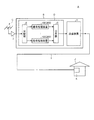
図1は、本発明の実施の形態1に係る信号処理装置の構成を示す図である。図1に示す
信号処理装置100は、FM放送の多チャンネル信号(ここでは単にFM信号と称する)
から視聴を希望する放送局の周波数信号(希望高周波信号、ここでは希望FM信号と称す
る)を選択処理して再送信するものである。ここでは、FM信号の周波数帯域は76MH
zから90MHzであるとする。したがって、希望FM信号の周波数は76MHzから9
0MHzの間の値であり、視聴を希望する放送局の周波数である。
(Embodiment 1)
FIG. 1 is a diagram showing a configuration of a signal processing device according to
The frequency signal (desired high frequency signal, here called the desired FM signal) of the broadcasting station that wants to view is selected and retransmitted. Here, the frequency band of the FM signal is 76 MH
Let z be 90 MHz. Therefore, the frequency of the desired FM signal ranges from 76 MHz to 9
It is a value between 0 MHz and the frequency of the broadcasting station that wants to watch.
この信号処理装置100は、信号入力部1と、ダウンコンバータ2と、中間周波数処理
部であるIF処理部3と、A/D変換部4と、ベースバンド変換部である直交復調部5と
、デジタルフィルタであるデジタルフィルタ6と、マルチパスキャンセラ7と、直交変調
D/A変換部8と、信号出力部9とがこの順番で接続された構成を有する。さらに、信号
処理装置100は、検波部10と、ダウンコンバータ2に局部発振周波数信号を供給する
局部発振部11とを備える。局部発振部11はたとえばPLL回路を用いて構成されてい
る。
The
ダウンコンバータ2は、イメージリジェクションフィルタ2aと、出力調整部としての
増幅部2bと、ミキサ2cとを備えている。また、IF処理部3は、第1バンドパスフィ
ルタであるIFバンドパスフィルタ(BPF)3aと、出力調整部としての増幅部3bと
、分岐部3cとを備えている。
The
信号処理装置100の動作を各構成要素の動作とともに説明する。なお、図2(a)、
図2(b)は、それぞれこの信号処理装置100の動作に関係する信号の周波数スペクト
ルの例を示す図である。以下では、適宜図2を参照して説明を行う。
The operation of the
FIG. 2B is a diagram illustrating an example of a frequency spectrum of a signal related to the operation of the
はじめに、外部から、アナログ信号であるFM信号やVHF帯域を含む広帯域の信号が信号入力部1に入力される。信号入力部1は入力された信号をダウンコンバータ2に出力する。
First, an FM signal that is an analog signal and a broadband signal including a VHF band are input to the
ダウンコンバータ2では、イメージリジェクションフィルタ2aは、入力されたFM信
号から、前記VHF帯域の成分を除去して透過する。なおイメージリジェクションフィル
タ2aは、周知のバンドパスフィルタなどで構成できる。
増幅部2bは、透過されたFM信号を増幅する。ミキサ2cは、局部発振部11が出力
する局部発振周波数信号と増幅されたFM信号とを混合し、IF信号に変換する。
In the
The amplifying
ここで、図2(a)に示すように、FM信号は所定の帯域BSを有しており、帯域BS
の周波数の下限値はfL、上限値はfHであるとする。また、符号S1は希望FM信号で
ある。信号処理装置100に入力されるFM信号は、希望FM信号S1およびこれと周波
数的に隣接したFM信号S2、S3も含め、帯域BSに含まれる他のFM信号も含む信号
である。
Here, as shown in FIG. 2A, the FM signal has a predetermined band BS, and the band BS
It is assumed that the lower limit value of f is f L and the upper limit value is f H. Reference S1 is a desired FM signal. The FM signal input to the
また、局部発振周波数信号SL1は、希望FM信号S1から中間周波数Δf1だけ離れ
た周波数に設定される。その結果、ミキサ2cが局部発振周波数信号SL1と希望FM信
号S1とを混合することにより、希望FM信号S1は中間周波数Δf1と等しい周波数を
有する、特定のIF信号(ここでは希望IF信号と称する)SIF1に変換される。IF
信号は希望IF信号および入力された他のFM信号が変換された成分を含むものとする。
ダウンコンバータ2は変換されたIF信号をIF処理部3に出力する。
Further, the local oscillation frequency signal SL1 is set to a frequency away from the desired FM signal S1 only intermediate frequency Delta] f 1. As a result, the
The signal includes a component obtained by converting a desired IF signal and another input FM signal.
The down
図2(a)に示すように、信号処理装置100に入力される信号には、FM信号の帯域
BSよりも高周波側に、信号処理装置100で処理すべき放送信号に対して不要波である
不要信号SU1として、VHF帯域が存在している。
As shown in FIG. 2A, the signal input to the
ここでは、図2(a)に示すように、不要信号SU1と局部発振周波数信号SL1との
周波数差ΔfUは中間周波数Δf1に近いまたは等しい設定とされているものとする。こ
のような周波数設定では、不要信号SU1とFM信号とがこの信号処理装置100に入力
された場合、ミキサ2cの出力において不要信号SU1のイメージ信号が希望IF信号S
IF1と近い、または等しい周波数に発生してしまう。
例えば、中間周波数Δf1は10.7MHzであり、FM信号の80MHzに対し、局
部発振周波数信号SL1の周波数は90.7MHzであり、もし不要信号SU1が、局部
発振周波数信号SL1よりも10.7MHzだけ高周波側(ΔfU=Δf1=10.7M
Hz)である、101.4MHzに存在している場合、周波数10.7MHzの希望IF
信号SIF1に対し、同じ周波数のイメージ信号が生じることになる。
このようなイメージ信号は混信の原因となるとともに、ダウンコンバータ2の後段での
除去が困難である。
Here, as shown in FIG. 2A, it is assumed that the frequency difference Δf U between the unnecessary signal SU1 and the local oscillation frequency signal SL1 is set to be close to or equal to the intermediate frequency Δf 1 . In such a frequency setting, when the unnecessary signal SU1 and the FM signal are input to the
It occurs at a frequency close to or equal to IF1.
For example, the intermediate frequency Δf 1 is 10.7 MHz, the frequency of the local oscillation frequency signal SL1 is 90.7 MHz with respect to 80 MHz of the FM signal, and the unnecessary signal SU1 is 10.7 MHz than the local oscillation frequency signal SL1. Only on the high frequency side (Δf U = Δf 1 = 10.7M
Hz), if present at 101.4 MHz, the desired IF with a frequency of 10.7 MHz
An image signal having the same frequency is generated for the signal SIF1.
Such an image signal causes interference and is difficult to remove in the subsequent stage of the
これに対して、このダウンコンバータ2では、イメージリジェクションフィルタ2aが
図2(a)中、IR1の点線で示すような透過帯域特性を持っており、入力された信号か
ら、VHF帯域の成分に含まれた不要信号SU1を除去する。したがって、その後のミキ
サ2cにおいて混信の原因となるイメージ信号の発生が抑制される(図2(a)の例では
、イメージ信号は十分小さなレベルとなっているため示されていない)。
On the other hand, in the
つぎに、IF処理部3の動作について説明する。IF処理部3では、IFバンドパスフ
ィルタ3aは、図2(a)に示すような透過帯域(図2(a)中の符号BF1で示す線を
参照)を有する周知のバンドパスフィルタで構成されており、ダウンコンバータ2から出
力されたIF信号に含まれる希望IF信号SIF1を含む所定の帯域を選択的に透過する
。増幅部3bは、透過されたIF信号を増幅する。分岐部3cは、増幅されたIF信号を
A/D変換部4に出力するとともに、IF信号の一部を分岐して検波部10側に出力する
。
Next, the operation of the IF processing unit 3 will be described. In the IF processing unit 3, the
つぎに、A/D変換部4、直交復調部5、デジタルフィルタ6、マルチパスキャンセラ
7、および直交変調D/A変換部8の動作について説明する。
Next, operations of the A /
A/D変換部4は、IF処理部3から出力されたIF信号をA/D変換してデジタルI
F信号とし、直交復調部5に出力する。直交復調部5は、デジタルIF信号を直交復調処
理してI信号とQ信号からなるデジタルベースバンド信号を生成する。このデジタルベー
スバンド信号には、希望FM信号S1のベースバンド信号の他に、隣接チャンネルの信号
S2,S3を含め他の信号帯域成分が含まれている。
The A /
An F signal is output to the
デジタルフィルタ6は、I信号とQ信号とのそれぞれに対して、所定の帯域を選択的に
透過し、上述の隣接チャンネルの信号を含め他の信号帯域成分を除去し、希望FM信号1
のベースバンド信号を抽出するデジタル信号処理を行う。このようなデジタル信号処理と
しては、たとえばFIR(有限インパルス応答)フィルタ処理が利用できる。
The
The digital signal processing for extracting the baseband signal is performed. As such digital signal processing, for example, FIR (finite impulse response) filter processing can be used.
マルチパスキャンセラ7は、デジタルフィルタ6を透過したI信号およびQ信号に含ま
れるマルチパスノイズを抑制して直交変調D/A変換部8に出力する。マルチパスキャン
セラ7は、たとえば特許文献2に記載の処理を行ってマルチパスノイズを抑制するような
、公知のマルチパスキャンセラを利用できる。
The
直交変調D/A変換部8は、このようにマルチパスノイズが抑制されたI信号およびQ
信号を用いて搬送波に直交変調処理を行い、希望FM信号S1を生成する。この希望FM
信号S1は信号出力部9から信号処理装置100の外部に出力される。ここでは、もとも
と受信したものと同じ希望FM信号S1に再変換しているが、他の周波数のFM信号また
はFM信号以外の高周波信号に再変換するようにしてもよい。
The quadrature modulation D /
The signal is subjected to orthogonal modulation processing on the carrier wave to generate a desired FM signal S1. This hope FM
The signal S1 is output from the signal output unit 9 to the outside of the
なお、検波部10は、分岐されて入力されたIF信号のレベルを検出し、ダウンコンバ
ータ2の増幅部2bとIF処理部3の増幅部3bとに対する利得一定制御(AGC)用の
制御信号を生成し、増幅部2b、3bのそれぞれに出力する。増幅部2b、3bは、制御
値に基づいて利得が設定される。ここで、制御値は、ミキサ2cに入力されるFM信号お
よびIF処理部3から出力されるIF信号の利得が一定になるように演算された制御値で
ある。これにより、ミキサ2cに入力されるFM信号およびIF処理部3から出力される
IF信号に対してAGCが実現される。なお、増幅部2b、3bは、増幅器の出力を調整
して利得を設定するものでもよいし、増幅器と減衰器とを備えており、増幅器の出力は一
定としつつ減衰器による減衰量を調整して利得を設定するものでもよい。
The
このように構成された信号処理装置100では、希望信号(希望IF信号SIF1また
はそのベースバンド信号)に対して、IFバンドパスフィルタ3aおよびデジタルフィル
タ6の2段階のフィルタ処理を行っている。これにより、IFバンドパスフィルタ3aに
要求される透過帯域特性(より具体的には透過帯域幅や減衰傾度(ロールオフ)等の特性
)が緩和される。すなわち、希望IF信号SIF1に隣接するIF信号がある程度IFバ
ンドパスフィルタ3aを透過してもよい。したがって、IFバンドパスフィルタ3aとし
ては、たとえば簡易なRLC回路で構成された、帯域内ディレー特性が良好なものを使用
できる。また、デジタルフィルタ6としても、帯域内ディレーが無くフラットな特性を有
する、たとえばFIRフィルタ処理を行うものを使用できる。これにより、信号処理装置
100が出力する希望FM信号S1は、FM受信機で受信した場合の音声信号の歪劣化が
少なくなる。
In the
このようにIFバンドパスフィルタ3aの透過帯域特性は緩和してもよい一方で、この
信号処理装置100では、IFバンドパスフィルタ3aから出力されるIF信号の全体レ
ベルをAGC制御に用いているため、このAGC制御が所望の精度で行える程度に隣接I
F信号がカットされるように、IFバンドパスフィルタ3aの透過帯域特性を設定するこ
とが好ましい。
Thus, while the transmission band characteristics of the
It is preferable to set the transmission band characteristic of the
また、信号処理装置100では、ダウンコンバータ2にて局部発振周波数信号SLを用
いた周波数変換を1段階のみ実施し、直交変調D/A変換部8では直交ベースバンド信号
からFM信号を直接生成している。これにより、最終的に出力される希望FM信号S1に
含まれる位相ノイズが少なくなる。その結果、音声信号のS/N特性が良好になる。
In the
また、希望IF信号の周波数(中間周波数)は、任意の周波数を用いることができるが
、イメージ信号による影響を小さくするためには、図2(a)に示すような周波数配置の
代わりに、図2(b)に示すように、一般によく用いられている中間周波数(図2(a)
では10.7MHz)よりも高い周波数を用いることが好ましい。
たとえば希望IF信号SIF2の周波数を希望IF信号SIF1よりもαだけ高くし、
中間周波数Δf2=Δf1+αとする。そうすると、局部発振周波数信号SL2の周波数
を、従来の局部発振周波数信号SL1よりもαだけ高周波側に設定することとなる。これ
によって、局部発振周波数信号SL2と不要信号SU1との周波数差が、ΔfU−αと小
さくなって、その結果、不要信号SU1のイメージ信号SIM1の周波数もΔfU−αと
低くなり、イメージ信号SIM1の周波数と、希望IF信号SIF2の周波数との周波数
差が大きくなる。したがって、希望IF信号SIF2に対するイメージ信号SIM1の影
響をより小さくすることができる。
また局部発振周波数信号SL2よりもΔfU+αだけ高い周波数側に不要信号SU2が
ある場合、ΔfUがΔf1と同じもしくは近い周波数であるので、希望IF信号SIF2
と同じ周波数にイメージ信号が発生することになる。そこでイメージリジェクションフィ
ルタ2aはこの不要信号SU2を除去することができる程度の透過帯域特性をもったもの
を使用する。
このように中間周波数をΔf1からΔf2=Δf1+αと高い周波数とすることにより
、図2(b)に示すように、イメージリジェクションフィルタ2aの透過帯域特性IR2
を、不要信号SU1はある程度除去できればよいので、図2(a)の場合の透過帯域特性
IR1よりも緩和することができるようになり、好ましい。
また希望IF信号の周波数の上限についても適切に設定することが好ましい。例えばF
M信号の場合、FM信号の帯域BSに対しても十分な周波数差を確保するため、FM信号
の帯域BSよりもある程度低い周波数に設定することが好ましい。
Further, the frequency (intermediate frequency) of the desired IF signal can be an arbitrary frequency, but in order to reduce the influence of the image signal, instead of the frequency arrangement as shown in FIG. As shown in FIG. 2 (b), a generally used intermediate frequency (FIG. 2 (a)
In this case, it is preferable to use a frequency higher than 10.7 MHz.
For example, the frequency of the desired IF signal SIF2 is set higher by α than the desired IF signal SIF1,
The intermediate frequency Δf 2 = Δf 1 + α. Then, the frequency of the local oscillation frequency signal SL2 is set to a higher frequency side by α than the conventional local oscillation frequency signal SL1. As a result, the frequency difference between the local oscillation frequency signal SL2 and the unnecessary signal SU1 is reduced to Δf U −α, and as a result, the frequency of the image signal SIM1 of the unnecessary signal SU1 is also reduced to Δf U −α. The frequency difference between the frequency of SIM1 and the frequency of desired IF signal SIF2 increases. Therefore, the influence of the image signal SIM1 on the desired IF signal SIF2 can be further reduced.
Further, when there is an unnecessary signal SU2 on the frequency side higher by Δf U + α than the local oscillation frequency signal SL2, Δf U is a frequency that is the same as or close to Δf 1 , so that the desired IF signal SIF2
An image signal is generated at the same frequency. Therefore, an
Thus, by setting the intermediate frequency as high as Δf 1 to Δf 2 = Δf 1 + α, as shown in FIG. 2B, the transmission band characteristic IR2 of the
Since the unnecessary signal SU1 only needs to be removed to some extent, the transmission band characteristic IR1 in the case of FIG. 2A can be relaxed, which is preferable.
It is also preferable that the upper limit of the frequency of the desired IF signal is set appropriately. For example, F
In the case of the M signal, in order to ensure a sufficient frequency difference with respect to the band BS of the FM signal, it is preferable to set the frequency to be somewhat lower than the band BS of the FM signal.
このようにイメージリジェクションフィルタ2aで不要信号SU2を除去してイメージ
信号SIM1の発生を抑制するとともに、上述のように中間周波数を高くした設定により
、IF処理部3に設けるIFバンドパスフィルタ3aにおいて除去すべき信号の周波数を
、希望信号(希望IF信号SIF2)の周波数から離間させることができるので、IFバ
ンドパスフィルタ3aの,図2(b)のBF2に示す透過帯域特性が緩和される。
以上のような効果を十分に得るために、希望IF信号SIF2の周波数(中間周波数Δ
f2)を、例えば高周波信号の帯域BSの下限値fLの1/2以上、上限値fHの1/2
以下の周波数、すなわち高周波信号がFM信号の場合には、希望IF信号SIF2の周波
数Δf2を38MHz以上45MHz以下の周波数、に設定することがさらに好ましい。
In this way, the
In order to sufficiently obtain the above effects, the frequency of the desired IF signal SIF2 (intermediate frequency Δ
f 2 ) is, for example, not less than 1/2 of the lower limit value f L of the band BS of the high-frequency signal and 1/2 of the upper limit value f H
When the following frequency, that is, when the high frequency signal is an FM signal, it is more preferable to set the frequency Δf 2 of the desired IF signal SIF2 to a frequency of 38 MHz to 45 MHz.
また、信号処理装置100では、A/D変換部4と直交変調D/A変換部8とを備えて
いるので、その間にデジタル処理によるマルチパスキャンセラ7を設け、マルチパスノイ
ズを低減しているので、さらに信号品質を高めることができる。
以上説明したように、本実施形態1の信号処理装置によれば、高周波信号の高品質な信
号処理を行うことができる。
Further, since the
As described above, according to the signal processing apparatus of the first embodiment, high-quality signal processing of high-frequency signals can be performed.
(比較形態1)
ここで、本発明の実施の形態1に係る信号処理装置100と対比する対象としての比較
形態1,2を説明する。図4は、比較形態1に係る信号処理装置の構成を示す図である。
図4に示す信号処理装置1000は、信号処理装置100と同様に、FM信号から希望F
M信号を選択処理して再送信するものである。
(Comparative form 1)
Here, Comparative Examples 1 and 2 as objects to be compared with the
Similar to the
The M signal is selectively processed and retransmitted.
この信号処理装置1000は、信号入力部1と、ダウンコンバータ20と、IF処理部
30と、アップコンバータ40と、検波部10と、局部発振部11とを備える。
The
ダウンコンバータ20は、FM信号の周波数帯を選択的に透過する広帯域のバンドパス
フィルタ20aと、増幅部2bと、2つのミキサ2cとを備えている。また、IF処理部
30は、IFバンドパスフィルタ30aと、分岐部3cと、リミッタ30dとを備えてい
る。また、アップコンバータ40は、2つのミキサ2cを備えている。
The down-
つぎに、信号処理装置1000の動作を各構成要素の動作とともに説明する。
はじめに、外部からFM信号を含む信号が信号入力部1に入力されると、信号入力部1は
入力された信号をダウンコンバータ20に出力する。
Next, the operation of the
First, when a signal including an FM signal is input from the outside to the
ダウンコンバータ20では、バンドパスフィルタ20aはFM信号を透過する。増幅部
2bは、透過されたFM信号を増幅する。2つのミキサ2cは、局部発振部11が出力す
る局部発振周波数信号と増幅されたFM信号とを混合し、IF信号に変換し、IF処理部
30に出力する。このように、ダウンコンバータ20は、イメージ信号等の不要波の除去
のためにFM信号からIF信号への変換を2段階で行っている。なお、IF信号の周波数
(中間周波数)は、FM信号に対して通常使用される10.7MHzに設定されている。
In the
IF処理部30では、IFバンドパスフィルタ30aは、隣接信号の除去や帯域外減衰
量確保のために、通常は急峻なセラミックフィルタやSAWフィルタが使用され、ダウン
コンバータ20から入力された10.7MHzのIF信号を選択的に透過する。分岐部3
cは、IFバンドパスフィルタ30aを透過したIF信号をリミッタ30dに出力すると
ともに、IF信号の一部を分岐して検波部10側に出力する。さらに、リミッタ30dは
、増幅されたIF信号のレベルを安定させてアップコンバータ40に出力する。
In the
c outputs the IF signal that has passed through the
アップコンバータ40では、2つのミキサ2cは、局部発振部11が出力する局部発振
周波数信号とIF信号とを混合し、FM信号に再変換する。このように、アップコンバー
タ40は、スプリアス除去等のためにIF信号からFM信号への変換を2段階で行ってい
る。再変換されたFM信号は信号出力部9から信号処理装置の外部に出力される。
In the up-
なお、検波部10は、分岐されて入力されたIF信号のレベルを検出し、ダウンコンバ
ータ20の増幅部2bに対する制御値を演算し、増幅部2bに出力する。増幅部2bは、
制御値に基づいて利得が設定される。これにより、ミキサ2cに入力されるFM信号に対
して利得一定制御(AGC)が実現される。
The
A gain is set based on the control value. Thus, constant gain control (AGC) is realized for the FM signal input to the
この信号処理装置1000では、局部発振周波数信号を用いた周波数変換を4段階実施
しているので、局部発振部11で発生する位相ノイズが、各周波数変換毎にFM信号に混
入してしまう。その結果、音声信号のS/N特性が劣化しやすくなる。また、中間周波数
として10.7MHzを選択し、これに対応して急峻なセラミックフィルタやSAWフィ
ルタを用いているため、帯域内ディレー特性が劣化しやすくなり、FM信号を受信機で受
信した場合に音声信号の歪劣化が発生しやすくなる。
In this
(比較形態2)
つぎに、図5は、比較形態2に係る信号処理装置の構成を示す図である。図5に示す信
号処理装置2000は、図4に示す信号処理装置1000のIF処理部30をIF処理部
30Aに置き換え、かつIF処理部30Aとアップコンバータ40との間に、ケーブル接
続により外付けでマルチパスキャンセル装置50を追加した構成を有する。
(Comparative form 2)
Next, FIG. 5 is a diagram illustrating a configuration of the signal processing device according to the second comparative example. A
IF処理部30Aは、IF処理部30のリミッタ30dを削除し、IFバンドパスフィ
ルタ30aと分岐部3cとの間に増幅部を追加した構成を有する。マルチパスキャンセル
装置50は、A/D変換部50aと、マルチパスキャンセラ50bと、D/A変換部50
cとを備えている。
The
c.
この信号処理装置2000の動作は基本的に信号処理装置1000の動作と同様である
が、以下の点で異なる。すなわち、マルチパスキャンセル装置50は、IF処理部30が
出力するIF信号を受け付け、A/D変換部50aがこれをデジタルIF信号にA/D変
換し、マルチパスキャンセラ50bに出力する。マルチパスキャンセラ50bは、入力さ
れたデジタルIF信号に含まれるマルチパスノイズを抑制してD/A変換部50cに出力
する。D/A変換部50cは、マルチパスノイズが抑制されたデジタルIF信号をIF信
号にD/A変換し、アップコンバータ40に出力する。なお、比較形態1のようにIF処
理部30Aでリミッタを用いると、マルチパスノイズの情報がなくなってしまうので、こ
の比較形態2のIF処理部30Aでは、IF信号に対して、検波部10と増幅器とによる
AGCを行っている。
The operation of the
この信号処理装置2000では、信号処理装置1000と同様に、位相ノイズによる音
声信号のS/N特性の劣化や、帯域内ディレー特性の劣化による音声信号の歪劣化が発生
しやすくなる。さらには、マルチパスキャンセラ50bのためにA/D変換部50aとD
/A変換部50cとを備えるようにしなければならないため、高コストになる。
In the
Since the / A
以上のような比較形態1,2に対して、本発明の実施の形態1に係る信号処理装置10
0では、音声信号のS/N特性や、音声信号の歪特性といった信号品質が向上する。また
、局部発振器の数を減らすことができるので構成が簡素化される。しかも高価なSAWフ
ィルタ等を使用する必要がないので、低コストな構成とすることができる。
Compared to the first and second comparative embodiments as described above, the
At 0, the signal quality such as the S / N characteristic of the audio signal and the distortion characteristic of the audio signal are improved. In addition, since the number of local oscillators can be reduced, the configuration is simplified. Moreover, since it is not necessary to use an expensive SAW filter or the like, a low-cost configuration can be achieved.
(実施の形態2)
図3は、本発明の実施の形態2に係る信号処理装置の構成を示す図である。図3に示す
信号処理装置200は、図1に示す信号処理装置100の構成において、IF処理部3を
IF処理部3Aに置き換え、分岐部12,演算部13,および制御部14を追加した構成
を有する。
(Embodiment 2)
FIG. 3 is a diagram showing the configuration of the signal processing apparatus according to
IF処理部3Aは、IF処理部3から分岐部3cを削除した構成を有する。
分岐部12は、デジタルフィルタ6の後段に設けられており、デジタルフィルタ6を透
過したI信号およびQ信号の一部を演算部13に出力する。
The
The branching
演算部13は、分岐したI信号およびQ信号が入力されると、これらから、IF処理部
3Aから出力されたIF信号のレベルを演算し、演算したレベルに関する情報を制御部1
4に出力する。制御部14は、入力されたIF信号のレベルの情報から、ダウンコンバー
タ2の増幅部2bとIF処理部3Aの増幅部3bとに対する利得一定制御(AGC)用の
制御値を演算し、増幅部2b、3bのそれぞれに出力する。増幅部2b、3bは、制御値
に基づいて利得が設定される。ここで、制御値は、ミキサ2cに入力されるFM信号およ
びIF処理部3Aから出力されるIF信号の利得が一定になるように演算された制御値で
ある。これにより、ミキサ2cに入力されるFM信号およびIF処理部3Aから出力され
るIF信号に対してAGCが実現される。なお、増幅部2b、3bは、増幅器の出力を調
整して利得を設定するものでもよいし、増幅器と減衰器とを備えており、増幅器の出力は
一定としつつ減衰器による減衰量を調整して利得を設定するものでもよい。
When the branched I signal and Q signal are input, the
4 is output. The control unit 14 calculates a control value for constant gain control (AGC) for the amplifying
ここで、デジタルフィルタ6を透過したI信号およびQ信号を演算に用いることにより
、IF処理部3Aから出力されたIF信号に含まれる希望IF信号のレベルをより正確に
求めることができる。その結果、希望IF信号または希望FM信号に対するAGCの精度
がより高いものとなる。
Here, by using the I signal and the Q signal that have passed through the
以下、上記実施形態1または2の信号処理装置の使用例について説明する。
図6は、上記実施形態1または2の信号処理装置を使用したCATVヘッドエンドと、
そのヘッドエンドを用いて構成されたCATVシステムの構成例である。
Hereinafter, usage examples of the signal processing apparatus according to the first or second embodiment will be described.
FIG. 6 shows a CATV headend using the signal processing apparatus of the first or second embodiment,
This is a configuration example of a CATV system configured using the head end.
図6に示すように、CATVシステムAは、FM信号を受信するアンテナCと、アンテ
ナCから伝送されたFM信号を信号処理するCATV局のCATVヘッドエンドBと、C
ATVヘッドエンドBから送出されたFM信号を伝送する信号伝送路Iと、信号伝送路I
を伝送されたFM信号を受ける、加入者宅Jに設けられた加入者宅装置Kとを備えている
。
As shown in FIG. 6, the CATV system A includes an antenna C that receives FM signals, a CATV head end B of a CATV station that processes the FM signals transmitted from the antenna C, and C
A signal transmission path I for transmitting the FM signal sent from the ATV head end B, and a signal transmission path I
And a subscriber home device K provided in the subscriber home J that receives the FM signal transmitted.
CATVヘッドエンドBは、アンテナCから増幅器Fを介して伝送されたFM信号を分
配する分配部である分配器Eと、分配器Eから分配されたそれぞれのFM信号を信号処理
する、複数の、実施形態1または2の信号処理装置100(200)と、各信号処理装置
100(200)で信号処理されたそれぞれの希望FM信号を混合して高品質のFM信号
として出力する混合部である混合器Gとを備えたFM受信装置Dと、FM受信装置Dから
出力されたFM信号と他のCATV信号とを混合し、増幅して出力(送出)する送信装置
Hとを備えている。
The CATV head end B is a distributor E that distributes the FM signal transmitted from the antenna C through the amplifier F, and a plurality of FM signals distributed from the distributor E, The signal processing apparatus 100 (200) according to the first or second embodiment and a mixing unit that is a mixing unit that mixes each desired FM signal that has been signal-processed by each signal processing apparatus 100 (200) and outputs the result as a high-quality FM signal. FM receiver D provided with device G, and transmitter H that mixes the FM signal output from FM receiver D and another CATV signal, amplifies and outputs (sends).
このようなCATVシステムAによれば、本実施形態1または2の信号処理装置100
(200)によって生成された高品質のFM信号を加入者宅Jに提供することができる。
According to such a CATV system A, the
The high-quality FM signal generated by (200) can be provided to the subscriber's home J.
なお、上記実施の形態では、FM信号およびIF信号の両方に対してAGCを行ってい
るが、FM信号およびIF信号のいずれか一方に対してAGCを行う構成としてもよい。
In the above embodiment, AGC is performed on both the FM signal and the IF signal, but AGC may be performed on either the FM signal or the IF signal.
また、上記実施の形態では、中間周波数は、FM信号の帯域BSの下限値fLの1/2
以上、上限値fHの1/2以下の周波数に設定されているが、中間周波数の上限値につい
ては、使用するIFバンドパスフィルタ3aの透過帯域特性に応じて、適宜微調整しても
よい。たとえば、IFバンドパスフィルタ3aの透過帯域特性において、高周波側のロー
ルオフが低周波数側のロールオフと比較して小さければ、それに応じて中間周波数の上限
値を高くしてもよい。
In the above embodiment, the intermediate frequency is ½ of the lower limit value f L of the band BS of the FM signal.
Although is set to 1/2 or less of the frequency of the upper limit value f H, the upper limit value of the intermediate frequency, in accordance with the transmission band characteristic of the
また、上記実施の形態では、入力される放送信号はFM信号であるが、衛星放送や地上
波デジタル放送などの他の放送信号でもよい。中間周波数の範囲は、入力される放送信号
の帯域の上限値と下限値とに応じて適宜設定される。
たとえば高周波信号がFM信号ではなく地上デジタル放送の信号である場合には、一般
によく使用されるのは37.15MHzであり、希望IF信号の周波数(中間周波数)と
しては37.15MHzよりも高い値に設定することが好ましい。
In the above embodiment, the input broadcast signal is an FM signal, but may be another broadcast signal such as satellite broadcast or terrestrial digital broadcast. The range of the intermediate frequency is set as appropriate according to the upper limit value and the lower limit value of the band of the input broadcast signal.
For example, when the high-frequency signal is not an FM signal but a terrestrial digital broadcast signal, generally used is 37.15 MHz, and the frequency (intermediate frequency) of the desired IF signal is higher than 37.15 MHz. It is preferable to set to.
また、上記実施の形態では、ノイズキャンセラを備えているが、本発明の実施の形態に
係る信号処理装置としては、ノイズキャンセラを削除した構成を採用してもよい。また、
イメージリジェクションフィルタは信号処理装置のダウンコンバータの前段に外付けする
ものを用いてもよい。
Moreover, although the noise canceller is provided in the above embodiment, a configuration in which the noise canceller is deleted may be employed as the signal processing device according to the embodiment of the present invention. Also,
An image rejection filter that is externally attached to the front stage of the down converter of the signal processing device may be used.
また本発明の信号処理装置は、必ずしもCATVヘッドエンドやCATVシステムで使
用されるものに限定されるものではない。
Further, the signal processing apparatus of the present invention is not necessarily limited to that used in the CATV head end or CATV system.
また、上記実施の形態により本発明が限定されるものではない。上述した各構成要素を
適宜組み合わせて構成したものも本発明に含まれる。また、さらなる効果や変形例は、当
業者によって容易に導き出すことができる。よって、本発明のより広範な態様は、上記の
実施の形態に限定されるものではなく、様々な変更が可能である。
Further, the present invention is not limited by the above embodiment. What was comprised combining each component mentioned above suitably is also contained in this invention. Further effects and modifications can be easily derived by those skilled in the art. Therefore, the broader aspect of the present invention is not limited to the above-described embodiment, and various modifications can be made.
1 信号入力部
2 ダウンコンバータ
2a イメージリジェクションフィルタ
2b、3b 増幅部
2c ミキサ
3、3A IF処理部
3a IFバンドパスフィルタ
3c、12 分岐部
4 A/D変換部
5 直交復調部
6 デジタルフィルタ
7 マルチパスキャンセラ
8 直交復調D/A変換部
9 信号出力部
10 検波部
11 局部発振部
13 演算部
14 制御部
100、200 信号処理装置
BF1、BF2 透過帯域
BS 帯域
BU 不要帯域
S1 希望FM信号
S2、S3 FM信号
SIF1、SIF2 希望IF信号
SL1、SL2 局部発振周波数信号
SU1、SU2 不要信号
A CATVシステム
B CATVヘッドエンド
C アンテナ
D FM受信装置
E 分波器
F 増幅器
G 混合器
H 送信装置
I 信号伝送路
J 加入者宅
K 加入者宅装置
DESCRIPTION OF
Claims (8)
前記ダウンコンバータに局部発振周波数信号を供給する局部発振部と、
前記中間周波数信号の所定の帯域を選択的に透過するバンドパスフィルタを有する中間周波数処理部と、
前記バンドパスフィルタを透過した中間周波数信号をA/D変換するA/D変換部と、
前記A/D変換した中間周波数信号からベースバンド信号を生成するベースバンド変換部と、
前記ベースバンド信号の所定の帯域を選択的に透過するデジタル信号処理を行うデジタルフィルタと、
前記デジタルフィルタを透過したベースバンド信号を高周波信号にD/A変換するD/A変換部と、
前記ダウンコンバータまたは該ダウンコンバータの前段に配されたイメージリジェクションフィルタと、
を備え、
前記高周波信号がFM信号であって、
前記ダウンコンバータは、前記入力された高周波信号を、該高周波信号の帯域の上限値の1/2以下の周波数かつ10.7MHzよりも高い周波数である中間周波数信号に変換することを特徴とする信号処理装置。 A down converter that converts an input high frequency signal into an intermediate frequency signal;
A local oscillator for supplying a local oscillation frequency signal to the down converter;
An intermediate frequency processing unit having a band-pass filter that selectively transmits a predetermined band of the intermediate frequency signal;
An A / D converter for A / D converting the intermediate frequency signal transmitted through the band-pass filter;
A baseband converter that generates a baseband signal from the A / D converted intermediate frequency signal;
A digital filter that performs digital signal processing that selectively transmits a predetermined band of the baseband signal;
A D / A converter for D / A converting a baseband signal transmitted through the digital filter into a high-frequency signal;
An image rejection filter disposed in the preceding stage of the down converter or the down converter;
With
The high-frequency signal is an FM signal,
The down-converter converts the input high-frequency signal into an intermediate frequency signal having a frequency equal to or lower than a half of the upper limit value of the band of the high-frequency signal and a frequency higher than 10.7 MHz. Processing equipment.
前記ダウンコンバータに局部発振周波数信号を供給する局部発振部と、
前記中間周波数信号の所定の帯域を選択的に透過するバンドパスフィルタを有する中間周波数処理部と、
前記バンドパスフィルタを透過した中間周波数信号をA/D変換するA/D変換部と、
前記A/D変換した中間周波数信号からベースバンド信号を生成するベースバンド変換部と、
前記ベースバンド信号の所定の帯域を選択的に透過するデジタル信号処理を行うデジタルフィルタと、
前記デジタルフィルタを透過したベースバンド信号を高周波信号にD/A変換するD/A変換部と、
前記ダウンコンバータまたは該ダウンコンバータの前段に配されたイメージリジェクションフィルタと、
を備え、
前記高周波信号が地上デジタル信号であって、
前記ダウンコンバータは、前記入力された高周波信号を、該高周波信号の帯域の上限値の1/2以下の周波数かつ37.15MHzよりも高い周波数である中間周波数信号に変換することを特徴とする信号処理装置。 A down converter that converts an input high frequency signal into an intermediate frequency signal;
A local oscillator for supplying a local oscillation frequency signal to the down converter;
An intermediate frequency processing unit having a band-pass filter that selectively transmits a predetermined band of the intermediate frequency signal;
An A / D converter for A / D converting the intermediate frequency signal transmitted through the band-pass filter;
A baseband converter that generates a baseband signal from the A / D converted intermediate frequency signal;
A digital filter that performs digital signal processing that selectively transmits a predetermined band of the baseband signal;
A D / A converter for D / A converting a baseband signal transmitted through the digital filter into a high-frequency signal;
An image rejection filter disposed in the preceding stage of the down converter or the down converter;
With
The high-frequency signal is a terrestrial digital signal,
The down-converter converts the input high-frequency signal into an intermediate frequency signal having a frequency equal to or lower than a half of the upper limit value of the band of the high-frequency signal and a frequency higher than 37.15 MHz. Processing equipment.
前記分岐した中間周波数信号のレベルを検出する検波部と、
前記検出した中間周波数信号のレベルに基づいて、前記高周波信号および前記中間周波数信号の少なくとも一つに対する利得を一定に調整する出力調整部と、
を備えることを特徴とする請求項1〜4のいずれか一つに記載の信号処理装置。 A branching part for branching a part of the intermediate frequency signal;
A detector for detecting a level of the branched intermediate frequency signal;
An output adjusting unit that adjusts a gain for at least one of the high-frequency signal and the intermediate-frequency signal to be constant based on the level of the detected intermediate-frequency signal;
The signal processing apparatus according to claim 1, comprising:
前記分岐したベースバンド信号から前記中間周波数信号のレベルを演算する演算部と、
前記演算した中間周波数信号のレベルに基づいて、前記高周波信号および前記中間周波数信号の少なくとも一つに対する利得を一定に調整する出力調整部と、
を備えることを特徴とする請求項1〜5のいずれか一つに記載の信号処理装置。 A branching part for branching a part of the baseband signal transmitted through the digital filter;
A calculation unit for calculating the level of the intermediate frequency signal from the branched baseband signal;
An output adjusting unit that adjusts a gain for at least one of the high-frequency signal and the intermediate-frequency signal to be constant based on the level of the calculated intermediate-frequency signal;
The signal processing apparatus according to claim 1, comprising:
前記受信装置から出力された高周波信号を送出する送信装置と、
を備えることを特徴とするCATVヘッドエンド。 A signal processing device according to any one of claims 1 to 6 and a plurality of signal processing devices that respectively perform signal processing on a high-frequency signal distributed by the distribution unit that distributes a high-frequency signal, and the signal processing device. A mixing unit that mixes the high-frequency signal signal-processed by the receiver, and
A transmission device for transmitting a high-frequency signal output from the reception device;
A CATV head end comprising:
前記CATVヘッドエンドの送信装置から送出された高周波信号を伝送する信号伝送路と、
前記信号伝送路を伝送された高周波信号を受ける、加入者宅に設けられた加入者宅装置と、
を備えることを特徴とするCATVシステム。 A CATV headend according to claim 7 provided in a CATV station;
A signal transmission path for transmitting a high-frequency signal transmitted from the CATV headend transmitter;
A subscriber premises device provided in the subscriber premises that receives the high-frequency signal transmitted through the signal transmission path; and
A CATV system comprising:
Priority Applications (1)
| Application Number | Priority Date | Filing Date | Title |
|---|---|---|---|
| JP2014074898A JP6200367B2 (en) | 2014-03-31 | 2014-03-31 | Signal processing apparatus, CATV head end, and CATV system |
Applications Claiming Priority (1)
| Application Number | Priority Date | Filing Date | Title |
|---|---|---|---|
| JP2014074898A JP6200367B2 (en) | 2014-03-31 | 2014-03-31 | Signal processing apparatus, CATV head end, and CATV system |
Publications (2)
| Publication Number | Publication Date |
|---|---|
| JP2015198312A JP2015198312A (en) | 2015-11-09 |
| JP6200367B2 true JP6200367B2 (en) | 2017-09-20 |
Family
ID=54547791
Family Applications (1)
| Application Number | Title | Priority Date | Filing Date |
|---|---|---|---|
| JP2014074898A Active JP6200367B2 (en) | 2014-03-31 | 2014-03-31 | Signal processing apparatus, CATV head end, and CATV system |
Country Status (1)
| Country | Link |
|---|---|
| JP (1) | JP6200367B2 (en) |
Family Cites Families (7)
| Publication number | Priority date | Publication date | Assignee | Title |
|---|---|---|---|---|
| JP2822975B2 (en) * | 1996-04-09 | 1998-11-11 | 日本電気株式会社 | Receiving machine |
| JPH10304331A (en) * | 1997-04-24 | 1998-11-13 | Miharu Tsushin Kk | Preliminary device at head end of catv system |
| JP2000217102A (en) * | 1999-01-26 | 2000-08-04 | Sharp Corp | Tuner for satellite broadcast reception |
| JP2008092476A (en) * | 2006-10-04 | 2008-04-17 | Niigata Seimitsu Kk | Receiving machine |
| JP4815414B2 (en) * | 2007-09-27 | 2011-11-16 | シャープ株式会社 | Communication circuit device |
| JP2010147697A (en) * | 2008-12-17 | 2010-07-01 | Toshiba Corp | Frequency conversion device |
| JP5402037B2 (en) * | 2009-02-05 | 2014-01-29 | 株式会社リコー | FM / AM demodulator, radio receiver, electronic device, and image correction adjustment method |
-
2014
- 2014-03-31 JP JP2014074898A patent/JP6200367B2/en active Active
Also Published As
| Publication number | Publication date |
|---|---|
| JP2015198312A (en) | 2015-11-09 |
Similar Documents
| Publication | Publication Date | Title |
|---|---|---|
| CN101563850B (en) | Techniques for Deterministically Reducing Signal Interference | |
| US20100167680A1 (en) | Controllable image cancellation in a radio receiver | |
| JP5453195B2 (en) | High frequency receiver and radio receiver | |
| CN1843011B (en) | OFDM signal demodulator circuit and OFDM signal demodulation method | |
| JP2012138769A (en) | Electronic tuner and electronic apparatus using the same | |
| JP3531510B2 (en) | AGC device | |
| JP6200367B2 (en) | Signal processing apparatus, CATV head end, and CATV system | |
| US7787059B2 (en) | Digital television receiver | |
| JP4618868B2 (en) | Digital broadcast receiver and segment number detection device | |
| EP1808970A2 (en) | Device and method for improving the carrier-to-noise ratio for a receiver with diversity | |
| JP3449164B2 (en) | Receiver | |
| JP4957734B2 (en) | Reception device, imaging device, and reception method | |
| KR102345314B1 (en) | Frequency modulating signal relay apparatus through digital signal process | |
| JP5145160B2 (en) | Receiving apparatus and receiving method | |
| JP7559440B2 (en) | Broadcast signal processing device, broadcast signal processing system, and broadcast signal processing method | |
| JP2010206312A (en) | Receiver, and reception method of the same | |
| JP4717675B2 (en) | Wireless receiver | |
| JP2008283296A (en) | Receiving device and receiving method | |
| KR100862519B1 (en) | Satellite Broadcasting Receiver and Multi-broadcasting System with Improved Noise Rejection | |
| JP2002359569A (en) | Broadcasting receiver | |
| KR101101627B1 (en) | Broadband broadcast receiver | |
| KR20050029569A (en) | Digital tv on channel repeater with digital adaptive correction | |
| JP2006148592A (en) | COFDM modulated signal receiver | |
| KR100710384B1 (en) | Broadcast receiver | |
| JP2000175164A (en) | Network interface module |
Legal Events
| Date | Code | Title | Description |
|---|---|---|---|
| A977 | Report on retrieval |
Free format text: JAPANESE INTERMEDIATE CODE: A971007 Effective date: 20160616 |
|
| A131 | Notification of reasons for refusal |
Free format text: JAPANESE INTERMEDIATE CODE: A131 Effective date: 20160802 |
|
| A521 | Request for written amendment filed |
Free format text: JAPANESE INTERMEDIATE CODE: A523 Effective date: 20160929 |
|
| A131 | Notification of reasons for refusal |
Free format text: JAPANESE INTERMEDIATE CODE: A131 Effective date: 20170207 |
|
| A521 | Request for written amendment filed |
Free format text: JAPANESE INTERMEDIATE CODE: A523 Effective date: 20170228 |
|
| TRDD | Decision of grant or rejection written | ||
| A01 | Written decision to grant a patent or to grant a registration (utility model) |
Free format text: JAPANESE INTERMEDIATE CODE: A01 Effective date: 20170801 |
|
| A61 | First payment of annual fees (during grant procedure) |
Free format text: JAPANESE INTERMEDIATE CODE: A61 Effective date: 20170825 |
|
| R150 | Certificate of patent or registration of utility model |
Ref document number: 6200367 Country of ref document: JP Free format text: JAPANESE INTERMEDIATE CODE: R150 |
|
| R250 | Receipt of annual fees |
Free format text: JAPANESE INTERMEDIATE CODE: R250 |
|
| R250 | Receipt of annual fees |
Free format text: JAPANESE INTERMEDIATE CODE: R250 |
|
| S531 | Written request for registration of change of domicile |
Free format text: JAPANESE INTERMEDIATE CODE: R313531 |
|
| R350 | Written notification of registration of transfer |
Free format text: JAPANESE INTERMEDIATE CODE: R350 |
|
| R250 | Receipt of annual fees |
Free format text: JAPANESE INTERMEDIATE CODE: R250 |
|
| R250 | Receipt of annual fees |
Free format text: JAPANESE INTERMEDIATE CODE: R250 |
|
| R250 | Receipt of annual fees |
Free format text: JAPANESE INTERMEDIATE CODE: R250 |
|
| R250 | Receipt of annual fees |
Free format text: JAPANESE INTERMEDIATE CODE: R250 |