JP6199537B2 - Inner liner manufacturing method - Google Patents
Inner liner manufacturing method Download PDFInfo
- Publication number
- JP6199537B2 JP6199537B2 JP2011276377A JP2011276377A JP6199537B2 JP 6199537 B2 JP6199537 B2 JP 6199537B2 JP 2011276377 A JP2011276377 A JP 2011276377A JP 2011276377 A JP2011276377 A JP 2011276377A JP 6199537 B2 JP6199537 B2 JP 6199537B2
- Authority
- JP
- Japan
- Prior art keywords
- inner liner
- tire
- thickness
- rubber sheet
- unvulcanized rubber
- Prior art date
- Legal status (The legal status is an assumption and is not a legal conclusion. Google has not performed a legal analysis and makes no representation as to the accuracy of the status listed.)
- Active
Links
Images


Description
本発明は、乗用車等の空気入りタイヤのインナーライナーの製造方法に関するものである。 The present invention relates to the production how Lee emissions toner liner of a pneumatic tire such as a passenger car.
空気入りタイヤの内側には、空気漏れを防止し、タイヤ空気圧を一定に保つ目的からインナーライナーが設けられている。 An inner liner is provided inside the pneumatic tire for the purpose of preventing air leakage and keeping the tire air pressure constant.
そして、従来のインナーライナーは、カレンダーロールを用いて、幅方向全長にわたって均一な厚みに形成されている(特許文献1、2参照)。 And the conventional inner liner is formed in uniform thickness over the full length in the width direction using a calendar roll (refer to patent documents 1 and 2).
インナーライナーは、前記のタイヤ空気圧を一定に保つ目的で配置されるが、前記のような厚みが均一なインナーライナーを使用した場合、ゴムボリュームが不足することにより、ビードリングと生タイヤとの間に隙間が生じて、エア残りが発生する可能性があった。この点について図8を用いて具体的に説明する。 The inner liner is arranged for the purpose of keeping the tire pressure constant. However, when the inner liner having a uniform thickness as described above is used, the rubber volume is insufficient, so that the bead ring and the green tire are not separated. There was a possibility that a gap was generated in the air and the remaining air was generated. This point will be specifically described with reference to FIG.
図8は、従来のインナーライナーを用いたタイヤの加硫前後の状態を示す図であって、(A)はタイヤ加硫前の状態を示す断面図、(B)はタイヤ加硫後の状態を示す断面図である。 FIG. 8 is a view showing a state before and after vulcanization of a tire using a conventional inner liner, in which (A) is a cross-sectional view showing a state before tire vulcanization, and (B) is a state after tire vulcanization. FIG.
加硫成形工程において、生タイヤTが金型内にセットされたとき、図8(A)に示すように、生タイヤTのビード部を保持するビードリング100と生タイヤTのビード部との間に隙間S1が生じることがある。
In the vulcanization molding process, when the green tire T is set in the mold, a
そして、そのような生タイヤTのタイヤ加硫時には、生タイヤTがブラダー102で金型の内面に押し付けられながら加熱されるため、生タイヤTのインナーライナー50のゴムが矢印F方向に向かって流動する。
When the raw tire T is vulcanized, since the raw tire T is heated while being pressed against the inner surface of the mold by the
しかし、このような事例では、ゴムボリュームが不足して隙間S1を埋めきることができない場合があり、図8(B)に示すように、トウ端点101の近傍にエア残り58が発生することがある。なお、図8において、52はチェーファー、54はカーカスプライ、56はビードコアである。
However, in such a case, there is a case where the rubber volume is insufficient and the gap S1 cannot be filled, and as shown in FIG. 8B, an air remaining 58 may occur in the vicinity of the
本発明は、上記に鑑み、タイヤ加硫時にインナーライナーのゴムの流れ不良によるエア残りの発生を防止することができるインナーライナーの製造方法を提供することを目的とする。 In view of the above, and an object thereof is to provide a manufacturing how Louis emission toner liner can prevent the air remaining caused by poor flow of the rubber of the innerliner in the tire vulcanization.
請求項1に記載の発明は、
幅方向全長にわたって均一な厚みの未加硫ゴムシートの幅方向の両端部を、所定の幅で折り重ねることにより、厚みが中央部の厚みより大きい肉厚部を形成することを特徴とするインナーライナーの製造方法である。
The invention described in claim 1
An inner portion characterized in that a thick portion larger in thickness than a central portion is formed by folding both end portions in the width direction of the unvulcanized rubber sheet having a uniform thickness over the entire length in the width direction with a predetermined width. It is a manufacturing method of a liner.
本発明によれば、タイヤ加硫時にインナーライナーのゴムの流れ不良によるエア残りの発生を防止することができるインナーライナーの製造方法を提供することができる。 According to the present invention, it is possible to provide a manufacturing how Louis emission toner liner it is possible to prevent the occurrence of air remaining due to defective flow of the rubber of the innerliner in the tire vulcanization.
以下、実施の形態に基づいて本発明を説明する。 Hereinafter, the present invention will be described based on embodiments.
A.インナーライナーおよびその製造方法
(第1の実施の形態)
1.インナーライナー
図1は、第1の実施の形態に係るインナーライナーを示す断面図、図2は、第1の実施の形態に係るインナーライナーの製造に用いられる製造装置を模式的に示す図である。
A. Inner liner and manufacturing method thereof (first embodiment)
1. Inner Liner FIG. 1 is a cross-sectional view showing an inner liner according to the first embodiment, and FIG. 2 is a view schematically showing a manufacturing apparatus used for manufacturing the inner liner according to the first embodiment. .
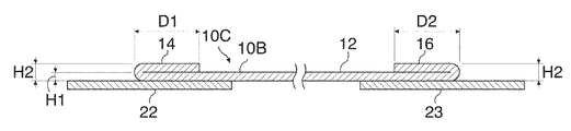
図1、図2に示すように、本実施の形態のインナーライナー10Aは、幅方向全長にわたって均一な厚みの未加硫ゴムシート12の両端部をスリッター装置34により裁断し、裁断された端部を、裁断された未加硫ゴムシート12の両端部に重ねて貼り付けることにより製造され、幅方向の両側辺部に厚みが中央部の厚みより大きい肉厚部14、16が形成されている。
As shown in FIGS. 1 and 2, the inner liner 10 </ b> A according to the present embodiment is obtained by cutting both ends of an
この結果、インナーライナー10Aの両端に形成された肉厚部14、16の厚みH2は、中央部の厚みH1の2倍に設定される。肉厚部14、16と中央部の段差については、段差が1.0mmを超えると段差によるエア残りが発生し易くなるため、0.5〜1.0mmに設定されることが好ましい。このため、中央部の厚みH1は0.5〜1.0mmが好ましく、肉厚部14、16の厚みH2は1.0〜2.0mmが好ましい。
As a result, the thickness H2 of the
また、肉厚部14、16の幅D1、D2は、10mm未満では厚み不足が発生し、一方、30mmを超えるとコストアップが大きくなるため、10〜30mmに設定されることが好ましい。
Further, the widths D1 and D2 of the
2.インナーライナーの製造方法
図2に示すように、インナーライナー10Aの製造方法に用いられる製造装置は、一対のカレンダーロール30a、30bを有するカレンダー装置30と、複数の搬送ローラ32a、32aを有する搬送ローラ連32と、搬送ローラ連32の上方に配設されているスリッター装置34と、一対の押えスポンジローラー36a、36bとを備えている。
2. 2. Inner Liner Manufacturing Method As shown in FIG. 2, the manufacturing apparatus used in the
スリッター装置34は、一対のアーム(図示省略)の先端にそれぞれスリッター刃34a、34bが装着されている。それぞれのスリッター刃34a、34bは、搬送ローラ32aのローラ幅方向に相互に所定の間隔を設けて配置されており、搬送ローラ連32の幅方向に水平移動して位置調整が可能になっている。
The
カレンダー装置30は、インナーライナー用ゴムGを一対のカレンダーロール30a、30aの間から送り出し、所定の幅寸法および厚さ寸法の未加硫ゴムシート12を形成する。
The
カレンダー装置30から送出された未加硫ゴムシート12は、搬送ローラ連32で搬送されながら、図3に示すように、未加硫ゴムシート12の両側辺部がスリッター装置34のスリッター刃34a、34bにより所定幅(10〜30mm)に裁断される。裁断により形成された端部片は、裁断後の未加硫ゴムシート12の端部に重ねられ、一対の押えスポンジローラー36a、36bの間を通過させることにより、端部片が、裁断後の未加硫ゴムシート12に貼り付けられてインナーライナー10Aが製造される。
While the
以上のように、本実施の形態によれば、肉厚部により、ビード周りのゴムボリュームを十分に確保することができ、タイヤ加硫時にインナーライナーのゴムの流れ不良によるエア残りの発生を防止することができる。また、両側辺部を裁断して、未加硫ゴムシートと貼り付けるだけで、容易に、肉厚部を形成してインナーライナーを製造することができる。 As described above, according to the present embodiment, the thick portion can secure a sufficient rubber volume around the bead, and prevents the occurrence of air residue due to poor rubber flow of the inner liner during tire vulcanization. can do. Moreover, a thick part can be easily formed and an inner liner can be manufactured only by cut | judging both sides and sticking with an unvulcanized rubber sheet.
(第2の実施の形態)
1.インナーライナー
図4は、第2の実施の形態に係るインナーライナー10Bを示す断面図である。図5は、第2の実施の形態に係るインナーライナー10Bの製造に用いられる製造装置を模式的に示す図である。
(Second Embodiment)
1. Inner Liner FIG. 4 is a cross-sectional view showing an
図4、図5に示すように、本実施の形態のインナーライナー10Bは、幅方向全長にわたって均一な厚みの未加硫ゴムシート12を、上記のように裁断することなく、未加硫ゴムシート12の両端部を折り重ねることにより形成され、両側辺部に厚みが中央部の厚みより大きい肉厚部14、16が形成されている。
As shown in FIGS. 4 and 5, the inner liner 10 </ b> B of the present embodiment is an unvulcanized rubber sheet without cutting the
インナーライナー10Bの肉厚部14、16の厚みH2、中央部の厚みH1、肉厚部14、16の幅D1、D2は、第1の実施の形態のインナーライナー10Aと同様に設定されている。
The thickness H2 of the
2.インナーライナーの製造方法 2. Inner liner manufacturing method
図5に示すように、インナーライナー10Bの製造方法に用いられる製造装置は、一対のカレンダーロール40a、40bを有するカレンダー装置40と、複数の搬送ローラ42aを有する搬送ローラ連42と、搬送ローラ連42の上方に配設される折り曲げ装置44と、一対の押えスポンジローラー46a、46bとを備えており、第1の実施の形態のインナーライナー10Aの製造装置とは、スリッター装置34に代えて折り曲げ装置44を備えている点で相違する。
As shown in FIG. 5, the manufacturing apparatus used in the method for manufacturing the
折り曲げ装置44は、一対の折り曲げ機構付きアーム44a、44bを備えており、それぞれのアーム44a、44bは、搬送ローラ42aのローラ幅方向に相互に所定の間隔を設けて配置されており、搬送ローラ連42の幅方向に水平移動して位置調整が可能になっている。
The bending
カレンダー装置40から送出された未加硫ゴムシート12は、搬送ローラ連42で搬送されながら、未加硫ゴムシート12の両端部が所定の幅寸法(10〜30mm)で、幅方向内側に曲げられて折り重ねられ、一対の押えスポンジローラー46a、46bの間を通過させることにより、インナーライナー10Bが製造される。
The
以上のように、本実施の形態によれば、両側辺部を折り曲げて、未加硫ゴムシートと折り重ねるだけで、容易に、エア残りの発生を充分に抑制することができるインナーライナーを製造することができる。 As described above, according to the present embodiment, it is possible to easily produce an inner liner that can sufficiently suppress the generation of remaining air by simply folding both sides and folding the uncured rubber sheet. can do.
(第3の実施の形態)
図6は、本発明の第3の実施の形態に係るインナーライナー10Cを示す断面図である。
(Third embodiment)
FIG. 6 is a sectional view showing an
図6に示すように、インナーライナー10Cは、第2の実施の形態のインナーライナー10Bの両端部14、16に補強材のチェーファー(キャンバスチェーファー)22、23がそれぞれ貼り付けられて形成されている。
As shown in FIG. 6, the
このため、タイヤリムと激しく擦れる部分を保護することが可能となり好ましい。 For this reason, it becomes possible to protect the part which rubs hard with a tire rim, and it is preferable.
B.タイヤおよびタイヤの製造方法
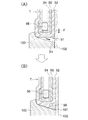
図7は本発明の実施の形態に係るタイヤの加硫前後の状態を示す図であって、(A)はインナーライナー10Cを用いて製造された生タイヤの加硫前の状態を示す断面図であり、(B)は加硫後の状態を示す断面図である。
B. FIG. 7 is a diagram illustrating a state before and after vulcanization of a tire according to an embodiment of the present invention, and FIG. 7 (A) is a diagram of a raw tire manufactured using an
図7(A)に示すように、加硫成形工程においては、従来のインナーライナーを使用した場合と同様に、生タイヤTが金型内にセットされたとき、生タイヤTのビード部1bを保持するビードリング100と生タイヤTのビード部1bとの間に隙間S2が生じる。
As shown in FIG. 7A, in the vulcanization molding process, when the raw tire T is set in the mold, the
そして、タイヤ加硫時には、生タイヤTがブラダー102で金型の内面に押し付けられながら加熱されるが、本実施の形態においては、図7(B)に示すように、充分のゴムボリュームを有するインナーライナー10Cのゴムが矢印F方向に向かって流動して隙間S2を確実に埋めることができる。
When the tire is vulcanized, the green tire T is heated while being pressed against the inner surface of the mold by the
すなわち、インナーライナー10Cは、上記のように両側片部に肉厚部16が設けられ肉厚部16の一部分16aがタイヤTのビード部1bのトウ端点6bを臨むように配置されている。このため、ビード部1bの周りのゴムボリュームが確保できる。この結果、隙間S2に十分なゴムが流れるため、図7(B)に示すように、隙間S2を埋めることができる。この結果、ビード部1bのトウ端点6bの近傍において、インナーライナーのゴムボリューム不足によるエア残りの発生が抑制され、エア残りの発生が少ないタイヤTを製造することができる。
That is, the inner liner 10 </ b> C is arranged so that the
なお、図7において、2はカーカスプライ、3bはビードコア、4bはビードフィラー、12は加硫ゴムシート、16は肉厚部、16aは肉厚部の一部、23はチェーファーである。 In FIG. 7, 2 is a carcass ply, 3b is a bead core, 4b is a bead filler, 12 is a vulcanized rubber sheet, 16 is a thick part, 16a is a part of the thick part, and 23 is a chafer.
1.実施例および比較例
表1に示す厚みの未加硫ゴムシートを用い、表1に示す折り曲げ量で両端を折り曲げて折り重ねたインナーライナー(実施例1〜6)、および均一な厚さのインナーライナー(比較例1、2)を用いて、タイヤサイズ195/65 R15のタイヤを作製した。
1. Examples and Comparative Examples Using an unvulcanized rubber sheet having the thickness shown in Table 1, an inner liner (Examples 1 to 6) in which both ends are folded and folded at the folding amount shown in Table 1, and an inner with a uniform thickness A tire having a tire size of 195/65 R15 was produced using the liner (Comparative Examples 1 and 2).
2.実施例および比較例の評価
作製された各タイヤについて、エア残り発生率を評価すると共に、タイヤコスト指数を評価した。エア残り発生率は、作製したタイヤのビード部の断面観察により評価した。タイヤコスト指数は、比較例1のタイヤの製造コストを100として評価した。評価結果を表1に示す。
2. Evaluation of Examples and Comparative Examples For each of the manufactured tires, an air remaining rate was evaluated and a tire cost index was evaluated. The air remaining generation rate was evaluated by observing a cross section of the bead portion of the manufactured tire. The tire cost index was evaluated assuming that the manufacturing cost of the tire of Comparative Example 1 was 100. The evaluation results are shown in Table 1.

表1より、厚さ2.0mmの均一なインナーライナーを使用したタイヤ(比較例2)は、ゴム量が十分あるため、比較例1に比べて、エア残り発生が低減されたが、コストが大幅にアップすることが分かる。 From Table 1, the tire (Comparative Example 2) using a uniform inner liner having a thickness of 2.0 mm has a sufficient amount of rubber, so that the occurrence of residual air is reduced compared to Comparative Example 1, but the cost is low. It turns out that it improves greatly.
これに対して、厚さ1.0mmの未加硫ゴムシートを用いて、10mmおよび30mmの折り曲げ量で作製されたインナーライナーを使用したタイヤ(実施例5、6)は、ゴム量を十分確保でき、エア残り発生率が0.02%、0.00%と小さいながらも、タイヤコスト指数が101、102と比較例とほぼ同じであることが分かる。 On the other hand, tires (Examples 5 and 6) using an inner liner made of unvulcanized rubber sheet having a thickness of 1.0 mm and bent at 10 mm and 30 mm have a sufficient amount of rubber. It can be seen that the tire cost index is 101, 102, which is almost the same as that of the comparative example, although the remaining air generation rate is as small as 0.02% and 0.00%.
また、実施例1(厚さ1.5mmの未加硫ゴムシートを用い、折り曲げ量が30mmのインナーライナーを使用したタイヤ)では、ゴム量を十分確保できたが、インナーライナーの段差が1.5mmと大きいため、段差を原因とするエア残りが発生し易くなり、エア残り発生率は1.20%と悪化した。 Further, in Example 1 (a tire using an unvulcanized rubber sheet having a thickness of 1.5 mm and an inner liner having a bending amount of 30 mm), a sufficient amount of rubber could be secured, but the level difference of the inner liner was 1. Since it is as large as 5 mm, it is easy to generate air residue due to a step, and the air residue generation rate deteriorated to 1.20%.
実施例2(厚さ1.0mmの未加硫ゴムシートを用い、折り曲げ量が50mmのインナーライナーを使用したタイヤ)では、ゴム量が十分あり、インナーライナーのゴム流れ不良を原因とするエア残り発生率が、0.00%となった。しかしながら、左右の肉厚部の折り曲げ量が大きいため、コストアップも大きくなった。 In Example 2 (a tire using an unvulcanized rubber sheet having a thickness of 1.0 mm and an inner liner having a bending amount of 50 mm), the amount of rubber is sufficient, and the air remaining due to poor rubber flow of the inner liner The incidence was 0.00%. However, since the amount of bending of the left and right thick portions is large, the cost increases.
実施例3(厚さ0.5mmの未加硫ゴムシートを用い、折り曲げ量が30mmのインナーライナーを使用したタイヤ)では、左右の肉厚部の厚みが小さいため、ゴム量が不十分で、エア残り発生率が1.10%と悪化した。 In Example 3 (a tire using an unvulcanized rubber sheet having a thickness of 0.5 mm and an inner liner having a bending amount of 30 mm), the thickness of the left and right thick portions is small, so the amount of rubber is insufficient. The remaining air generation rate deteriorated to 1.10%.
実施例4(厚さ1.0mmの未加硫ゴムシートを用い、折り曲げ量が5mmのインナーライナーを使用したタイヤ)では、左右の肉厚部の折り曲げ量が小さいためゴム量が不十分で、比較例1に近いエア残り発生率となった。 In Example 4 (a tire using an unvulcanized rubber sheet having a thickness of 1.0 mm and an inner liner having a bending amount of 5 mm), the amount of rubber is insufficient because the bending amount of the left and right thick portions is small. The air remaining rate was close to that of Comparative Example 1.
以上、本実施の形態によれば、タイヤ加硫時にインナーライナーのゴムボリューム不足によるエア残りの発生を防止することができ、さらに、インナーライナーの肉厚部および中央部の厚み、肉厚部の幅を適切に設定することにより、タイヤ重量や材料コストの増加をも抑制することができる。 As described above, according to the present embodiment, it is possible to prevent the occurrence of remaining air due to insufficient rubber volume of the inner liner during tire vulcanization, and further, the thickness of the thick part and the central part of the inner liner, By appropriately setting the width, it is possible to suppress an increase in tire weight and material cost.
以上、本発明を実施の形態に基づいて説明したが、本発明は上記の実施の形態に限定されるものではない。本発明と同一および均等の範囲内において、上記の実施の形態に対して種々の変更を加えることができる。 While the present invention has been described based on the embodiments, the present invention is not limited to the above embodiments. Various modifications can be made to the above-described embodiments within the same and equivalent scope as the present invention.
1a、1b、51 ビード部
2、54 カーカスプライ
3a、3b、56 ビードコア
4a、4b ビードフィラー
6a、6b、101 トウ端点
10A、10B、10C、50 未加流インナーライナー
12 未加硫ゴムシート
14、16 肉厚部
16a 肉厚部の一部
22、23、52 チェーファー
30 カレンダー装置
30a、30b カレンダーロール
32、42 搬送ローラ連
32a、42a 搬送ローラ
34 スリッター装置
34a、34b スリッター刃
36a、36b、46a、46b 押えスポンジローラー
40 カレンダー装置
44 折り曲げ装置
44a、44b アーム
58 エア残り
100 ビードリング
102 ブラダー
D1、D2 左右の肉厚部の幅(折り曲げ量)
F ゴムの流動方向
G インナーライナー用ゴム
H1 インナーライナーの中央部の厚み
H2 インナーライナーの端部の厚み
S1、S2 隙間
T 生タイヤ
1a, 1b, 51
6a, 6b, 101
F Flow direction of rubber G Rubber for inner liner H1 Thickness of central portion of inner liner H2 Thickness of end of inner liner S1, S2 Clearance T Raw tire
Claims (1)
Priority Applications (1)
| Application Number | Priority Date | Filing Date | Title |
|---|---|---|---|
| JP2011276377A JP6199537B2 (en) | 2011-12-16 | 2011-12-16 | Inner liner manufacturing method |
Applications Claiming Priority (1)
| Application Number | Priority Date | Filing Date | Title |
|---|---|---|---|
| JP2011276377A JP6199537B2 (en) | 2011-12-16 | 2011-12-16 | Inner liner manufacturing method |
Publications (2)
| Publication Number | Publication Date |
|---|---|
| JP2013126801A JP2013126801A (en) | 2013-06-27 |
| JP6199537B2 true JP6199537B2 (en) | 2017-09-20 |
Family
ID=48777604
Family Applications (1)
| Application Number | Title | Priority Date | Filing Date |
|---|---|---|---|
| JP2011276377A Active JP6199537B2 (en) | 2011-12-16 | 2011-12-16 | Inner liner manufacturing method |
Country Status (1)
| Country | Link |
|---|---|
| JP (1) | JP6199537B2 (en) |
Families Citing this family (1)
| Publication number | Priority date | Publication date | Assignee | Title |
|---|---|---|---|---|
| JP7424070B2 (en) | 2020-01-22 | 2024-01-30 | 住友ゴム工業株式会社 | Tire manufacturing method and raw tires |
Family Cites Families (2)
| Publication number | Priority date | Publication date | Assignee | Title |
|---|---|---|---|---|
| JP2978472B1 (en) * | 1998-05-11 | 1999-11-15 | 住友ゴム工業株式会社 | Pneumatic tire |
| JP2002103476A (en) * | 2000-10-05 | 2002-04-09 | Bridgestone Corp | Method for manufacturing pneumatic tire |
-
2011
- 2011-12-16 JP JP2011276377A patent/JP6199537B2/en active Active
Also Published As
| Publication number | Publication date |
|---|---|
| JP2013126801A (en) | 2013-06-27 |
Similar Documents
| Publication | Publication Date | Title |
|---|---|---|
| JP4904054B2 (en) | Manufacturing method of rubber member for tire | |
| JP5462817B2 (en) | Pneumatic tire manufacturing method | |
| JP5667433B2 (en) | Tire vulcanization mold and method for manufacturing pneumatic tire | |
| JP6199537B2 (en) | Inner liner manufacturing method | |
| JP2005335369A (en) | Manufacturing method of pneumatic tire | |
| EP3263362B1 (en) | Pneumatic tire | |
| JP6296906B2 (en) | Raw tire molding method and band drum | |
| EP2671729A1 (en) | Pneumatic tire and method for manufacturing same | |
| JP2009202471A (en) | Method of manufacturing tire for heavy loading | |
| JP2008213750A (en) | Pneumatic tire and manufacturing method for pneumatic tire | |
| JP6412418B2 (en) | Edge strip manufacturing apparatus and method, and cutting apparatus | |
| WO2016076176A1 (en) | Pneumatic tire manufacturing method, and pneumatic tire | |
| WO2016076175A1 (en) | Pneumatic tire manufacturing method, and pneumatic tire | |
| JP2012040780A (en) | Method of manufacturing pneumatic tire, and pneumatic tire | |
| JP2016083888A (en) | Presser device for tire molding and tire molding method | |
| JP6448962B2 (en) | Stitching roll for green tire molding | |
| JP2006347063A (en) | Pneumatic tire and its manufacturing method | |
| JP2019116236A (en) | Pneumatic tire | |
| JP6136131B2 (en) | Rehabilitation tire | |
| JP2014201276A (en) | Tire and method for production thereof | |
| JP2017094853A (en) | Tire and method for manufacturing the same | |
| JP2016049750A (en) | Tire molding method | |
| JP6536204B2 (en) | Method of manufacturing pneumatic tire | |
| JP5767509B2 (en) | Pneumatic tire manufacturing method | |
| JP5559563B2 (en) | Tire manufacturing method |
Legal Events
| Date | Code | Title | Description |
|---|---|---|---|
| A621 | Written request for application examination |
Free format text: JAPANESE INTERMEDIATE CODE: A621 Effective date: 20141017 |
|
| A977 | Report on retrieval |
Free format text: JAPANESE INTERMEDIATE CODE: A971007 Effective date: 20150924 |
|
| A131 | Notification of reasons for refusal |
Free format text: JAPANESE INTERMEDIATE CODE: A131 Effective date: 20151005 |
|
| A521 | Request for written amendment filed |
Free format text: JAPANESE INTERMEDIATE CODE: A523 Effective date: 20151118 |
|
| A131 | Notification of reasons for refusal |
Free format text: JAPANESE INTERMEDIATE CODE: A131 Effective date: 20160509 |
|
| A521 | Request for written amendment filed |
Free format text: JAPANESE INTERMEDIATE CODE: A523 Effective date: 20160707 |
|
| A131 | Notification of reasons for refusal |
Free format text: JAPANESE INTERMEDIATE CODE: A131 Effective date: 20170105 |
|
| A521 | Request for written amendment filed |
Free format text: JAPANESE INTERMEDIATE CODE: A523 Effective date: 20170223 |
|
| TRDD | Decision of grant or rejection written | ||
| A01 | Written decision to grant a patent or to grant a registration (utility model) |
Free format text: JAPANESE INTERMEDIATE CODE: A01 Effective date: 20170731 |
|
| A61 | First payment of annual fees (during grant procedure) |
Free format text: JAPANESE INTERMEDIATE CODE: A61 Effective date: 20170824 |
|
| R150 | Certificate of patent or registration of utility model |
Ref document number: 6199537 Country of ref document: JP Free format text: JAPANESE INTERMEDIATE CODE: R150 |
|
| R250 | Receipt of annual fees |
Free format text: JAPANESE INTERMEDIATE CODE: R250 |
|
| R250 | Receipt of annual fees |
Free format text: JAPANESE INTERMEDIATE CODE: R250 |
|
| R250 | Receipt of annual fees |
Free format text: JAPANESE INTERMEDIATE CODE: R250 |
|
| R250 | Receipt of annual fees |
Free format text: JAPANESE INTERMEDIATE CODE: R250 |