JP6196977B2 - Automatic switching dual power supply light - Google Patents
Automatic switching dual power supply light Download PDFInfo
- Publication number
- JP6196977B2 JP6196977B2 JP2014539147A JP2014539147A JP6196977B2 JP 6196977 B2 JP6196977 B2 JP 6196977B2 JP 2014539147 A JP2014539147 A JP 2014539147A JP 2014539147 A JP2014539147 A JP 2014539147A JP 6196977 B2 JP6196977 B2 JP 6196977B2
- Authority
- JP
- Japan
- Prior art keywords
- light source
- level
- power
- light
- illumination
- Prior art date
- Legal status (The legal status is an assumption and is not a legal conclusion. Google has not performed a legal analysis and makes no representation as to the accuracy of the status listed.)
- Expired - Fee Related
Links
Images


Classifications
-
- H—ELECTRICITY
- H05—ELECTRIC TECHNIQUES NOT OTHERWISE PROVIDED FOR
- H05B—ELECTRIC HEATING; ELECTRIC LIGHT SOURCES NOT OTHERWISE PROVIDED FOR; CIRCUIT ARRANGEMENTS FOR ELECTRIC LIGHT SOURCES, IN GENERAL
- H05B35/00—Electric light sources using a combination of different types of light generation
-
- E—FIXED CONSTRUCTIONS
- E04—BUILDING
- E04G—SCAFFOLDING; FORMS; SHUTTERING; BUILDING IMPLEMENTS OR AIDS, OR THEIR USE; HANDLING BUILDING MATERIALS ON THE SITE; REPAIRING, BREAKING-UP OR OTHER WORK ON EXISTING BUILDINGS
- E04G23/00—Working measures on existing buildings
- E04G23/006—Arrangements for removing of previously fixed floor coverings
-
- H—ELECTRICITY
- H05—ELECTRIC TECHNIQUES NOT OTHERWISE PROVIDED FOR
- H05B—ELECTRIC HEATING; ELECTRIC LIGHT SOURCES NOT OTHERWISE PROVIDED FOR; CIRCUIT ARRANGEMENTS FOR ELECTRIC LIGHT SOURCES, IN GENERAL
- H05B47/00—Circuit arrangements for operating light sources in general, i.e. where the type of light source is not relevant
- H05B47/10—Controlling the light source
Description
本発明は、太陽パネルにより電力供給されるLED配列および主電源により電力供給される蛍光灯から、建築物の内部の照明のために供給される電力のタイプの制御に関する。 The present invention relates to the control of the type of power supplied for lighting inside a building from an LED array powered by a solar panel and a fluorescent lamp powered by a main power source.
主電源の電力消費を相殺するために、太陽パネルおよび他の代替の電源が、現在の建築物に追加されたり、または新しい建築物の設計に組み込まれたりしてきた。これらのシステムでは、太陽パネルは、日照ピーク時にはより高い電力出力を、非ピーク時にはより低い電力出力を提供してきた。これが、太陽パネルで生成された電力の目的が照明であるときに、ある問題を発生させた。太陽電池の非ピーク電力出力が、所定のライト一式を点灯させるには不十分であった。 To offset the power consumption of the main power source, solar panels and other alternative power sources have been added to current buildings or incorporated into new building designs. In these systems, solar panels have provided higher power output during peak sunshine hours and lower power output during non-peak hours. This created a problem when the purpose of the power generated by the solar panel was lighting. The non-peak power output of the solar cell was insufficient to light a given set of lights.
業界での設計は、バッテリを照明システムに組み込むことでこの問題を克服しようとした。バッテリによって、電力を日照ピーク時に蓄えて、非ピーク時に必要とされる時に用いることが可能となった。太陽方式やバッテリの設置には制限が存在した。第一に、ピーク時の電力出力は、使用中の光源とバッテリの充電とに分けられる必要があった。このため、所定の設置先で必要とされる太陽電池の数が増した。また、最初にバッテリを設置するのに追加の費用が生じ、バッテリも所定の時間が経てば交換する必要があった。太陽方式およびバッテリの設置には、複雑で経費のかかる設置に備えた、大規模な制御回路を必要とした。 Industry designs have attempted to overcome this problem by incorporating batteries into the lighting system. The battery allows power to be stored during peak sunshine hours and used when needed during non-peak hours. There were limitations to solar and battery installation. First, the peak power output needed to be divided into a light source in use and a battery charge. For this reason, the number of solar cells required at a predetermined installation destination has increased. In addition, there is an additional cost for installing the battery for the first time, and the battery has to be replaced after a predetermined time. Solar and battery installations required large control circuits in preparation for complex and expensive installations.
この問題を克服する他の設計では、太陽パネルで生成された電力または建築物の主電源によって電力供給される照明システムを必要とした。これらの設置が太陽パネルやバッテリの設置に勝る1つの長所は、初期設置の経費が軽減されることであった。加えて、これらのシステムはさらに、主電源の電力消費を減少させるという目的を達成した。このタイプの設置では、太陽パネル電源と主電源との間の変換をいつ、そしてどのようにして行うかという問題が存在していた。この分野では、光電池が用いられていた。光電池などのセンサーがこの光電池センサーの電圧出力に基づいてある光レベルを検出した。光電池は、夜明けまたは夕暮れ時に存在する照明レベルを検出するために、また、その信号に基づいて明かりを制御するために、戸外の照明設置先で用いられてきた。 Other designs that overcome this problem required a lighting system powered by solar panel generated power or by the building's main power source. One advantage of these installations over solar panel and battery installations is that initial installation costs are reduced. In addition, these systems further achieved the goal of reducing the power consumption of the main power supply. In this type of installation, there was the question of when and how to convert between solar panel power and mains power. Photovoltaic cells have been used in this field. A sensor such as a photovoltaic cell detected a light level based on the voltage output of the photovoltaic cell sensor. Photovoltaic cells have been used in outdoor lighting installations to detect the lighting level present at dawn or dusk and to control the light based on the signal.
米国公開特許出願第2011/0032695号は、建築物の主電源との接続を持つ太陽電池式ライトアセンブリに関する。太陽パネルは、発光ダイオード配列に電力供給する充電式バッテリと、白熱電球に経路付けされた建築物の主電源とに電力を供給していた。このライトアセンブリは、1つの光電池センサーに従って戸外の周辺光レベルを感知して、夕暮れ時に所定の周辺光レベルが感知された時に、充電式バッテリから電力供給される発光ダイオード配列をオンにしていた。第2の光電池センサーは、発光ダイオード配列の光レベルを感知して、発光ダイオード配列に供給された光の量が、充電式バッテリが電力切れになる時のような所定の最小レベル未満である時に、白熱電球に対する電力をオンにしていた。このアセンブリは、日中と、屋内での照明設置先もしくは充電式バッテリが存在しない設置先に欠点があった。このアセンブリの1つの欠点は、第2の光電池が、筐体の中の双方の光源からの光出力を直接に感知していたことである。双方の光源からの出力を感知することにより、一旦白熱電球がオンにされると、発光ダイオード配列の光出力を感知する制御システムは、もはや機能しなくなった。このシナリオでは、白熱電球は、夜明けまで、または電球が手動でオフにされるまでは、オンのままである。 US Published Patent Application No. 2011/0032695 relates to a solar powered light assembly with connection to the main power source of the building. The solar panel supplied power to the rechargeable battery that supplied power to the light emitting diode array and the main power source of the building routed to the incandescent bulb. The light assembly senses outdoor ambient light levels according to a single photovoltaic sensor and turns on a light emitting diode array powered by a rechargeable battery when a predetermined ambient light level is sensed at dusk. The second photovoltaic cell sensor senses the light level of the light emitting diode array and when the amount of light supplied to the light emitting diode array is below a predetermined minimum level, such as when the rechargeable battery is out of power. The power to the incandescent bulb was on. This assembly has drawbacks during the daytime and indoor lighting installations or installations where there is no rechargeable battery. One drawback of this assembly is that the second photovoltaic cell directly sensed the light output from both light sources in the housing. By sensing the output from both light sources, once the incandescent bulb was turned on, the control system sensing the light output of the light emitting diode array no longer worked. In this scenario, the incandescent bulb remains on until dawn or until the bulb is manually turned off.
米国公開特許出願第2009/0224681号は、ハイブリッド式の太陽電池および送電網式照明システムに関する。この出願は、照明設置先に対して、太陽パネル電力と送電網電力とを切り替える、または、太陽パネル電力と送電網電力との組み合わせに切り替えるシステムを説明していた。具体的には、このシステムは、所定の照明設置先のために追加される必要がある送電網電力の量を判定するために、太陽パネルによって生成された電力量の現在の測定結果を利用していた。これを遂行するには複雑な回路が必要であり、それが、このシステムを実現するために経費を増大させた。 US Published Patent Application No. 2009/0224681 relates to a hybrid solar cell and grid lighting system. This application has described a system for switching between solar panel power and grid power, or switching to a combination of solar panel power and grid power for a lighting installation. Specifically, this system uses current measurements of the amount of power generated by the solar panel to determine the amount of grid power that needs to be added for a given lighting installation. It was. To accomplish this requires complex circuitry, which increases the cost to implement this system.
本発明は、太陽パネル電力をより効率的に利用し、これにより送電網電力消費を軽減する新しい、改良された照明システムを提供する。この照明システムは、周辺光が送電網からの電気の使用量を軽減することを可能とするとき、利用可能な太陽エネルギーを用いて、建築物の内部に照明を提供する。この照明システムは、複数のLED灯および複数の蛍光灯を持つ照明配列を有する。太陽電池パネルは、この照明配列の中のLED灯に電力を提供し、光電池は、建築物の内部空間内の周辺光レベルを感知する。制御機構は、感知された周辺光レベルが、照明目的のLED灯の利用に対する規定されたレベル未満であるときに、蛍光灯を作動させるために光電池によって作動される。 The present invention provides a new and improved lighting system that utilizes solar panel power more efficiently, thereby reducing grid power consumption. This lighting system uses the available solar energy to provide lighting inside the building when ambient light allows the use of electricity from the grid to be reduced. The illumination system has an illumination arrangement with a plurality of LED lamps and a plurality of fluorescent lamps. The solar panel provides power to the LED lights in this lighting arrangement, and the photovoltaic cell senses the ambient light level in the interior space of the building. The control mechanism is activated by the photovoltaic cell to activate the fluorescent lamp when the sensed ambient light level is below a specified level for use of the LED lamp for illumination purposes.
本発明は、太陽電池パネルによって電力供給される一次光源からの照明と、主電源から電力供給される二次光源からの照明との自動照明制御によるエネルギー節約に関する。本発明は、照明と光感知との双方が建築物の内部空間に存在する用途に特に適合される。 The present invention relates to energy savings by automatic illumination control of illumination from a primary light source powered by a solar panel and illumination from a secondary light source powered from a main power source. The present invention is particularly adapted for applications where both lighting and light sensing are present in the interior space of a building.
図1は、本発明に係る、例示的な自動照明制御システムを図示する。一次光源30は、太陽電池パネル20によって電力供給されるLED灯の配列として示されている。LED灯配列は、太陽電池パネル20が、通常の日当たりの良い条件下で入射光線を受容しているときに、建築物または筐体の内部に十分な照明を提供する。光電池抵抗体センサー機構50は、一次光源30のLED灯からの光出力を監視する。光電池抵抗体センサー機構50は、主送電網60からの電力の二次光源40に対する流れを光電池抵抗体センサー機構50によって感知された光に基づいて制御するスイッチ70に電気的に接続される。二次光源40は、送電網60によって電力供給される。送電網60は、任意の数の源から電力を受容し得る。電源は、これには限られないが、地方公共事業プロバイダによって提供される電力または現地の発電機からの電力を含み得る。他の送電網電力源もまた利用され得ることを理解されたい。
FIG. 1 illustrates an exemplary automatic lighting control system according to the present invention. The
好ましい実施形態は、一次光源用の発光ダイオードまたはLED30の配列と、二次光源40としての蛍光灯とを用いる。LED配列は一般的には、他の利用可能な光源より消費エネルギー1ワット当りでより多くの光線を提供することが可能であり、これが、目的が送電網の電力消費を軽減することであるときに、太陽パネル電源とLED灯光源との組み合わせを有利なものとする。
The preferred embodiment uses an array of light emitting diodes or
比較すると、蛍光ランプは一般的には、設置するのにLED配列より経済的であり、現在の多くの建築物の設置先では既に、蛍光ランプを利用している。本発明は、蛍光器具を既に設置している現在の建築物の設計に組み込まれ得る、または、本発明は新しい建築物の設計に用いられ得る。蛍光灯は、エネルギー効率の良い光源であることが望ましいが、他のものを用いても良い。一次光源用にLED以外の光源も用いられ得ることを理解されたい。光源には、LED、蛍光灯、白熱電球が含まれ得るが、必要に応じて、他の既存の照明源を一次光源用に用い得る。更に、好ましい本実施形態は、直射日光によってもたらされる熱を軽減するために、戸外の太陽パネル設置物、または照らされている建築物または筐体の窓もしくは屋根で部分的日よけとして設置される太陽パネルを利用し得る。 In comparison, fluorescent lamps are generally more economical to install than LED arrays, and many current building installations already use fluorescent lamps. The present invention can be incorporated into the design of current buildings that already have fluorescent equipment installed, or the present invention can be used in the design of new buildings. The fluorescent lamp is desirably an energy efficient light source, but other fluorescent lamps may be used. It should be understood that light sources other than LEDs may be used for the primary light source. Light sources can include LEDs, fluorescent lights, and incandescent bulbs, but other existing illumination sources can be used for the primary light source, if desired. Furthermore, the preferred embodiment is installed as a partial sunshade on an outdoor solar panel installation, or an illuminated building or enclosure window or roof, to reduce the heat generated by direct sunlight. Solar panels can be used.
図2は、本発明に係る、照明システムの概略図または機能ブロック図である。太陽電池パネル20は、複数の太陽電池を有する。この太陽電池パネルの構成は、太陽条件、建築物の構造に対する考慮、予測される電力需要のピーク値および平均値、等に従って、いずれかの適切な従来型であり得る。加えて、複数の太陽電池パネルが、太陽電池パネル20用に用いられ得る。太陽電池パネル20は、屋内のLED配列30に接続し、これに電力を供給する。
FIG. 2 is a schematic or functional block diagram of a lighting system according to the present invention. The
光電池抵抗体センサー制御機構50は、屋内LED配列30の光出力を感知する光電池抵抗体を含む。所定の設置先で、光電池抵抗体154は、LED配列30の近くで照らされている建築物の中に配置され、光電池抵抗体154が、一次光源30の周辺照明レベルを感知するようにする。LED配列30の光出力が、規定された照明レベルを上回って上昇するとき、二次光源40に対する電力の流れは、スイッチ70によって遮断される。光電池抵抗体センサー機構50は、光電池抵抗体センサー機構50がLED配列30の光出力が規定されたレベル未満であることを感知するときに、スイッチ70が二次のまたは電力供給された光源40に対する送電網電力60の流れを許容することを可能にする。加えて、光電池抵抗体センサー制御機構50が、LED配列30が規定されたレベルを上回る照明レベルを再度達成したと感知するとき、光電池抵抗体センサー制御機構50は、スイッチ70に対して、送電網60から二次光源40への流れを停止させ、これにより、送電網を利用しないで電力消費を軽減させる。
The photovoltaic resistor
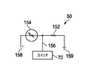
図3は、感光性の電池で形成される、市販タイプの光電池抵抗体154を含む、光電池抵抗体センサー機構50をさらに詳細に図示する。光電池抵抗体154は、電圧源158で電圧基準レベルと、159に示すように電気的アースに接続されている抵抗体152とに接続される。光電池抵抗体154と抵抗体152との間に位置する接続ポイント156は、光電池抵抗体154の抵抗値で決定される電圧レベルを示し、この抵抗値は次に建築物中の感知された周辺照明レベルによって決まる。所望の周辺照明レベルでは、光電池抵抗体154の抵抗値は、抵抗体152と実質的に同じであり、したがって、ポイント156は、電圧源158の電圧の半分である電圧レベルにある。
FIG. 3 illustrates the photovoltaic
光電池抵抗体154の電池は、光に敏感であり、一次光源30によって提供されるような、感知された入射光線レベルに基づいて、抵抗値の変化を示す。光源30から提供される光線が適切であるときは、光電池抵抗体154の電池の、実際には光電池の端子の抵抗値が増加して、スイッチ70に至る接続ポイント156で提示される電圧が変化する。光源30からの光線が減少すると、光電池抵抗体154の電池の抵抗値が減少して、スイッチ70に至る接続ポイント156で提示される電圧が変化する。この性能によって、本発明は、需要が感知されたときに、二次光源40のライトを作動し、一次光源30から十分な光線が存在するときには、自動的にこれらをオフに切り替える。
The cell of
光電池抵抗体154上のLED灯30による照明が夕暮れ、曇りがちな天気、または他の理由のために減少するとき、光電池抵抗体の抵抗値が減少し、したがって、ポイント156における電圧が変化する。ポイント156に接続されている電圧感応スイッチ70は、LED灯30からの許容不可能照明出力を示す電圧レベルに高感度に設定されている。したがって、ポイント156での電圧が、設定または規定されたレベルでは存在しないとき、電圧感応スイッチが70を閉じて、送電網60から二次光源40に電力が流れることを可能とする。
When the illumination by the
逆に、光電池抵抗体154上のLED灯30による照明が、夜明け、曇りがちな天気の通過、または他の理由のために増大するとき、光電池抵抗体の抵抗値が増大し、したがって、ポイント156における電圧が変化する。ポイント156での電圧が、設定または規定されたレベルを満たすとき、電圧感応スイッチ70が開き、送電網60から二次光源40に対する電力の流れが停止する。
Conversely, when the illumination by the
このように、本発明により、照明目的のためのデュアル光源システムを持つ照明システムが提供される。一次光源30のLED灯は、太陽電池20によって動作され、二次光源40は、送電網60の主電源からの動作電力を受容する。照明目的の適切な電力供給への切り替えは、制御機構50が一次光源のLED灯からの低照明出力を感知するときに自動的に行われて、電力消費を最適化する。本発明は、太陽エネルギーを、太陽電池パネル20から利用可能な分量だけ引き出し、建築物の照明の必要性が求められるときにだけ、送電網から照明用の補助電力に切り替える。
Thus, the present invention provides an illumination system having a dual light source system for illumination purposes. The LED lamp of the
本発明は、関連事項の平均的知識を持つ人物が、本明細書の発明の中で言及される成果を再現し、かつ獲得し得るように十分に説明された。それでもなお、本明細書中の本発明の主題である技術分野のいかなる当業者も、本明細書中の要求に述べられていない修正を実施し、これらの修正を決定された構造またはこの構造の製造プロセスに応用し、以下の特許請求の範囲で請求される事項を要求し得るが、これらの構造は、本発明の範囲内に網羅されるものとする。 The present invention has been fully described so that a person with average knowledge of the relevant matters can reproduce and obtain the results mentioned in the invention herein. Nonetheless, any person skilled in the art that is the subject of the present invention will make modifications not stated in the requirements herein and these modifications will be determined or determined for this structure. Applicable to manufacturing processes and may require the matters claimed in the following claims, but these structures are intended to be covered within the scope of the present invention.
添付の特許請求の範囲に記載された本発明の精神および範囲から逸脱することなく、詳細に上述した本発明に対して改善および修正が可能であることを留意し、理解すべきである。
It should be noted and understood that improvements and modifications may be made to the invention described above in detail without departing from the spirit and scope of the invention as set forth in the appended claims.
Claims (14)
複数のLED灯および複数の蛍光灯を備える照明配列と、
前記照明配列の中の前記複数のLED灯に電力を提供する太陽電池パネルと、
前記建築物の前記内部における前記複数のLED灯の光レベルを感知する光電池と、
前記感知された前記複数のLED灯の光レベルが、照明目的で前記複数のLED灯の利用のために規定されたレベル未満であるときに、前記複数の蛍光灯を作動させ、前記複数の蛍光灯が作動しており、前記複数のLED灯の光レベルが規定されたレベルを上回る照明レベルを再度達成したと前記光電池が感知したときに、前記複数の蛍光灯への電力の流れを停止させるように前記光電池によって作動される制御機構と、
を備える、照明システム。 A lighting system for illuminating the interior of a building with available solar energy,
An illumination arrangement comprising a plurality of LED lamps and a plurality of fluorescent lamps;
A solar panel that provides power to the plurality of LED lights in the illumination arrangement;
A photovoltaic cell for sensing a light level of the plurality of LED lamps in the interior of the building;
The sensed plurality of LED lamp light level, when defined is less than the level for the use of the plurality of LED lamps in lighting purposes, it actuates the plurality of fluorescent lamps, the plurality of fluorescent When the photocell senses that the lamp is operating and that the light level of the plurality of LED lamps has again achieved an illumination level that exceeds a prescribed level, the flow of power to the plurality of fluorescent lamps is stopped. A control mechanism operated by the photovoltaic cell as
A lighting system comprising:
第1の光源および第2の光源を備える照明配列と、
前記照明配列の中の前記第1の光源に電力を提供する太陽電池パネルと、
前記建築物の前記内部における前記第1の光源の光レベルを感知する光電池と、
前記感知された前記第1の光源の光レベルが、照明目的で前記第1の光源の利用のために規定されたレベル未満であるときに、前記第2の光源を作動させ、前記第2の光源が作動しており、前記第1の光源の光レベルが規定されたレベルを上回る照明レベルを再度達成したと前記光電池が感知したときに、前記第2の光源への電力の流れを停止させるように前記光電池によって作動される制御機構と、
を備える、照明システム。 A lighting system for illuminating the interior of a building with available solar energy,
An illumination arrangement comprising a first light source and a second light source;
A solar panel for providing power to the first light source in the illumination arrangement;
A photovoltaic cell for sensing a light level of the first light source in the interior of the building;
The sensed light level of the first light source, when defined is less than the level for the use of the first light source in illumination purposes, it activates the second light source, the second When the light source is activated and the photovoltaic cell senses again that the light level of the first light source has re-achieved an illumination level that exceeds a specified level, the flow of power to the second light source is stopped. A control mechanism operated by the photovoltaic cell as
A lighting system comprising:
太陽電池パネルからの電力を用いて、照明配列の中の第1の光源に電力を提供するステップと、
前記建築物の前記内部における前記第1の光源の光レベルを感知するステップと、
前記感知された前記第1の光源の光レベルが、照明目的で前記第1の光源の利用のために規定されたレベル未満であるときを判定するステップと、
前記感知された前記第1の光源の光レベルが前記規定されたレベル未満であるときに、建築物の配電網からの電力を用いて、第2の光源に対する電力を作動させ、前記第2の光源が作動しており、前記第1の光源の光レベルが規定されたレベルを上回る照明レベルを再度達成したときに、前記第2の光源への電力の流れを停止させるステップと、
を備える、方法。 A method for illuminating the interior of a building with available solar energy,
Providing power to the first light source in the illumination arrangement using power from the solar panel;
Sensing the light level of the first light source in the interior of the building;
Determining when the sensed light level of the first light source is below a level defined for use of the first light source for illumination purposes;
When the sensed light level of the first light source is less than the defined level, using power from the grid of the building, it activates the power to the second light source, the second light source is operating, when the light level of the first light source has achieved a level of illumination above the defined level again, the steps of Ru stopping the flow of power to the second light source,
A method comprising:
前記電圧感応スイッチに応答して、前記第2の光源に対して電力が流れることを選択的に可能にすることを更に備える、請求項12に記載の方法。 The step of actuating comprises:
13. The method of claim 12, further comprising selectively enabling power to flow to the second light source in response to the voltage sensitive switch.
The method of claim 11, further comprising sensing light output from the first light source with a photovoltaic cell.
Applications Claiming Priority (3)
| Application Number | Priority Date | Filing Date | Title |
|---|---|---|---|
| US201161553531P | 2011-10-31 | 2011-10-31 | |
| US61/553,531 | 2011-10-31 | ||
| PCT/US2012/062666 WO2013066923A1 (en) | 2011-10-31 | 2012-10-31 | Auto switch dual power lights |
Publications (3)
| Publication Number | Publication Date |
|---|---|
| JP2014534588A JP2014534588A (en) | 2014-12-18 |
| JP2014534588A5 JP2014534588A5 (en) | 2015-08-27 |
| JP6196977B2 true JP6196977B2 (en) | 2017-09-13 |
Family
ID=47436164
Family Applications (1)
| Application Number | Title | Priority Date | Filing Date |
|---|---|---|---|
| JP2014539147A Expired - Fee Related JP6196977B2 (en) | 2011-10-31 | 2012-10-31 | Automatic switching dual power supply light |
Country Status (4)
| Country | Link |
|---|---|
| US (2) | US20130239511A1 (en) |
| EP (1) | EP2774458A1 (en) |
| JP (1) | JP6196977B2 (en) |
| WO (1) | WO2013066923A1 (en) |
Families Citing this family (3)
| Publication number | Priority date | Publication date | Assignee | Title |
|---|---|---|---|---|
| WO2014024200A1 (en) * | 2012-08-08 | 2014-02-13 | Ghost Rohit Neil | Device for generating electricity by harnessing solar energy and method thereof |
| CN203504278U (en) * | 2013-08-28 | 2014-03-26 | 广州凯明照明器具有限公司 | Solar power supply device and solar illumination equipment |
| US10652964B1 (en) * | 2018-02-26 | 2020-05-12 | Energy Bank Incorporated | Systems and methods related to photovoltaic direct drive lighting systems |
Family Cites Families (14)
| Publication number | Priority date | Publication date | Assignee | Title |
|---|---|---|---|---|
| JPS6063837A (en) * | 1983-09-19 | 1985-04-12 | 松下電器産業株式会社 | Electronic automatic flasher |
| JPH0665162B2 (en) * | 1985-06-25 | 1994-08-22 | 松下電工株式会社 | Lighting load automatic flashing device |
| US4983809A (en) * | 1989-08-01 | 1991-01-08 | Uas Automation Systems, Inc. | Radiant floor tile heater |
| US5098506A (en) * | 1991-03-12 | 1992-03-24 | Blw, Inc. | Method and apparatus for removing floor tile mastic |
| US5525182A (en) * | 1995-08-16 | 1996-06-11 | Miller; Joseph P. | Apparatus and method for wet removal of floor tile |
| US6027174A (en) * | 1998-01-26 | 2000-02-22 | John C. Gerbasi | Method and apparatus for removing ceramic tile |
| JP4448411B2 (en) * | 2004-09-03 | 2010-04-07 | 矢崎総業株式会社 | Light control system for interior lighting equipment |
| NL1034237C2 (en) * | 2007-08-08 | 2009-02-10 | Etap Nv | Lighting system. |
| US20090224681A1 (en) | 2008-03-10 | 2009-09-10 | S & A Solar Technologies, Inc. | Hybrid Solar Powered and Grid Powered Lighting System |
| WO2009131622A2 (en) * | 2008-04-25 | 2009-10-29 | Herrick Todd M | Solar-powered valance-mounted lighting system |
| EP3089558A3 (en) * | 2008-11-26 | 2017-01-18 | Wireless Environment, LLC | Wireless lighting devices and applications |
| US8348453B2 (en) * | 2009-08-10 | 2013-01-08 | Cumberland Holly S | Solar powered light assembly |
| EP2547175B1 (en) * | 2010-03-11 | 2020-05-06 | Rohm Co., Ltd. | Illumination system |
| US8591625B2 (en) * | 2011-11-13 | 2013-11-26 | International Business Machines Corporation | Server rack front door with contamination filter and sensor |
-
2012
- 2012-09-12 US US13/612,722 patent/US20130239511A1/en not_active Abandoned
- 2012-10-31 EP EP12806728.7A patent/EP2774458A1/en not_active Ceased
- 2012-10-31 WO PCT/US2012/062666 patent/WO2013066923A1/en active Application Filing
- 2012-10-31 JP JP2014539147A patent/JP6196977B2/en not_active Expired - Fee Related
- 2012-10-31 US US13/665,176 patent/US20130106293A1/en not_active Abandoned
Also Published As
| Publication number | Publication date |
|---|---|
| US20130106293A1 (en) | 2013-05-02 |
| EP2774458A1 (en) | 2014-09-10 |
| WO2013066923A4 (en) | 2013-07-04 |
| JP2014534588A (en) | 2014-12-18 |
| WO2013066923A1 (en) | 2013-05-10 |
| US20130239511A1 (en) | 2013-09-19 |
Similar Documents
| Publication | Publication Date | Title |
|---|---|---|
| US10856380B2 (en) | Photovoltaic lighting system having integrated control board, and monitoring system using same | |
| US8348453B2 (en) | Solar powered light assembly | |
| KR101829359B1 (en) | Led illumination device for fluorescent light fixture | |
| US10816151B2 (en) | Lighting system | |
| CN104620459A (en) | Device for generating electricity by harnessing solar energy and method thereof | |
| JP6196977B2 (en) | Automatic switching dual power supply light | |
| JP2020536345A (en) | LED lighting system and its method | |
| WO2009131622A2 (en) | Solar-powered valance-mounted lighting system | |
| US20110089839A1 (en) | System and method of indoor solar illumination | |
| CN105491762A (en) | Solar streetlamp control system and device | |
| CN101639190A (en) | Solar building public lighting device | |
| CN2859987Y (en) | Luminous diode wall lamp | |
| JP2014160630A (en) | Lighting device | |
| KR20160086588A (en) | Solar street light controlled by smart phone | |
| KR20220110392A (en) | Automatic street light charging/discharging system using solar panel | |
| CN201487795U (en) | Solar building pubic illumination device | |
| KR100943749B1 (en) | Solar photovoltaic street light | |
| CN212510921U (en) | Outdoor solar garden lamp device with timing switch | |
| CN204153670U (en) | Novel energy-saving environment-friendly road lamp device | |
| CN210891381U (en) | Intelligent solar street lamp | |
| CN216531847U (en) | Intelligent building public area illumination dimming system based on photoelectric complementation | |
| KR20110062936A (en) | Street lamp by solar cell | |
| JP6029924B2 (en) | Lighting system | |
| KR200430285Y1 (en) | The controller saving a power of a security light | |
| EP3772235A1 (en) | Control system integrated with a solar lighting ficture |
Legal Events
| Date | Code | Title | Description |
|---|---|---|---|
| A521 | Request for written amendment filed |
Free format text: JAPANESE INTERMEDIATE CODE: A523 Effective date: 20150708 |
|
| A621 | Written request for application examination |
Free format text: JAPANESE INTERMEDIATE CODE: A621 Effective date: 20150708 |
|
| A977 | Report on retrieval |
Free format text: JAPANESE INTERMEDIATE CODE: A971007 Effective date: 20160425 |
|
| A131 | Notification of reasons for refusal |
Free format text: JAPANESE INTERMEDIATE CODE: A131 Effective date: 20160517 |
|
| A601 | Written request for extension of time |
Free format text: JAPANESE INTERMEDIATE CODE: A601 Effective date: 20160815 |
|
| A601 | Written request for extension of time |
Free format text: JAPANESE INTERMEDIATE CODE: A601 Effective date: 20161017 |
|
| A521 | Request for written amendment filed |
Free format text: JAPANESE INTERMEDIATE CODE: A523 Effective date: 20161101 |
|
| A131 | Notification of reasons for refusal |
Free format text: JAPANESE INTERMEDIATE CODE: A131 Effective date: 20170307 |
|
| A521 | Request for written amendment filed |
Free format text: JAPANESE INTERMEDIATE CODE: A523 Effective date: 20170607 |
|
| TRDD | Decision of grant or rejection written | ||
| A01 | Written decision to grant a patent or to grant a registration (utility model) |
Free format text: JAPANESE INTERMEDIATE CODE: A01 Effective date: 20170808 |
|
| A61 | First payment of annual fees (during grant procedure) |
Free format text: JAPANESE INTERMEDIATE CODE: A61 Effective date: 20170821 |
|
| R150 | Certificate of patent or registration of utility model |
Ref document number: 6196977 Country of ref document: JP Free format text: JAPANESE INTERMEDIATE CODE: R150 |
|
| R250 | Receipt of annual fees |
Free format text: JAPANESE INTERMEDIATE CODE: R250 |
|
| R250 | Receipt of annual fees |
Free format text: JAPANESE INTERMEDIATE CODE: R250 |
|
| LAPS | Cancellation because of no payment of annual fees |