JP6194080B2 - Separation device and use thereof - Google Patents
Separation device and use thereof Download PDFInfo
- Publication number
- JP6194080B2 JP6194080B2 JP2016162526A JP2016162526A JP6194080B2 JP 6194080 B2 JP6194080 B2 JP 6194080B2 JP 2016162526 A JP2016162526 A JP 2016162526A JP 2016162526 A JP2016162526 A JP 2016162526A JP 6194080 B2 JP6194080 B2 JP 6194080B2
- Authority
- JP
- Japan
- Prior art keywords
- settler
- settling
- inlet opening
- inflow
- baffle plate
- Prior art date
- Legal status (The legal status is an assumption and is not a legal conclusion. Google has not performed a legal analysis and makes no representation as to the accuracy of the status listed.)
- Active
Links
Images


Classifications
-
- B—PERFORMING OPERATIONS; TRANSPORTING
- B01—PHYSICAL OR CHEMICAL PROCESSES OR APPARATUS IN GENERAL
- B01D—SEPARATION
- B01D21/00—Separation of suspended solid particles from liquids by sedimentation
- B01D21/0039—Settling tanks provided with contact surfaces, e.g. baffles, particles
- B01D21/0042—Baffles or guide plates
-
- B—PERFORMING OPERATIONS; TRANSPORTING
- B01—PHYSICAL OR CHEMICAL PROCESSES OR APPARATUS IN GENERAL
- B01D—SEPARATION
- B01D21/00—Separation of suspended solid particles from liquids by sedimentation
- B01D21/0039—Settling tanks provided with contact surfaces, e.g. baffles, particles
- B01D21/0045—Plurality of essentially parallel plates
-
- B—PERFORMING OPERATIONS; TRANSPORTING
- B01—PHYSICAL OR CHEMICAL PROCESSES OR APPARATUS IN GENERAL
- B01D—SEPARATION
- B01D21/00—Separation of suspended solid particles from liquids by sedimentation
- B01D21/0039—Settling tanks provided with contact surfaces, e.g. baffles, particles
- B01D21/0057—Settling tanks provided with contact surfaces, e.g. baffles, particles with counter-current flow direction of liquid and solid particles
-
- C—CHEMISTRY; METALLURGY
- C12—BIOCHEMISTRY; BEER; SPIRITS; WINE; VINEGAR; MICROBIOLOGY; ENZYMOLOGY; MUTATION OR GENETIC ENGINEERING
- C12M—APPARATUS FOR ENZYMOLOGY OR MICROBIOLOGY; APPARATUS FOR CULTURING MICROORGANISMS FOR PRODUCING BIOMASS, FOR GROWING CELLS OR FOR OBTAINING FERMENTATION OR METABOLIC PRODUCTS, i.e. BIOREACTORS OR FERMENTERS
- C12M27/00—Means for mixing, agitating or circulating fluids in the vessel
- C12M27/02—Stirrer or mobile mixing elements
-
- C—CHEMISTRY; METALLURGY
- C12—BIOCHEMISTRY; BEER; SPIRITS; WINE; VINEGAR; MICROBIOLOGY; ENZYMOLOGY; MUTATION OR GENETIC ENGINEERING
- C12M—APPARATUS FOR ENZYMOLOGY OR MICROBIOLOGY; APPARATUS FOR CULTURING MICROORGANISMS FOR PRODUCING BIOMASS, FOR GROWING CELLS OR FOR OBTAINING FERMENTATION OR METABOLIC PRODUCTS, i.e. BIOREACTORS OR FERMENTERS
- C12M27/00—Means for mixing, agitating or circulating fluids in the vessel
- C12M27/18—Flow directing inserts
- C12M27/20—Baffles; Ribs; Ribbons; Auger vanes
-
- C—CHEMISTRY; METALLURGY
- C12—BIOCHEMISTRY; BEER; SPIRITS; WINE; VINEGAR; MICROBIOLOGY; ENZYMOLOGY; MUTATION OR GENETIC ENGINEERING
- C12M—APPARATUS FOR ENZYMOLOGY OR MICROBIOLOGY; APPARATUS FOR CULTURING MICROORGANISMS FOR PRODUCING BIOMASS, FOR GROWING CELLS OR FOR OBTAINING FERMENTATION OR METABOLIC PRODUCTS, i.e. BIOREACTORS OR FERMENTERS
- C12M33/00—Means for introduction, transport, positioning, extraction, harvesting, peeling or sampling of biological material in or from the apparatus
- C12M33/22—Settling tanks; Sedimentation by gravity
-
- C—CHEMISTRY; METALLURGY
- C12—BIOCHEMISTRY; BEER; SPIRITS; WINE; VINEGAR; MICROBIOLOGY; ENZYMOLOGY; MUTATION OR GENETIC ENGINEERING
- C12M—APPARATUS FOR ENZYMOLOGY OR MICROBIOLOGY; APPARATUS FOR CULTURING MICROORGANISMS FOR PRODUCING BIOMASS, FOR GROWING CELLS OR FOR OBTAINING FERMENTATION OR METABOLIC PRODUCTS, i.e. BIOREACTORS OR FERMENTERS
- C12M47/00—Means for after-treatment of the produced biomass or of the fermentation or metabolic products, e.g. storage of biomass
- C12M47/02—Separating microorganisms from the culture medium; Concentration of biomass
-
- B—PERFORMING OPERATIONS; TRANSPORTING
- B01—PHYSICAL OR CHEMICAL PROCESSES OR APPARATUS IN GENERAL
- B01D—SEPARATION
- B01D2221/00—Applications of separation devices
- B01D2221/06—Separation devices for industrial food processing or agriculture
Landscapes
- Chemical & Material Sciences (AREA)
- Life Sciences & Earth Sciences (AREA)
- Health & Medical Sciences (AREA)
- Engineering & Computer Science (AREA)
- Wood Science & Technology (AREA)
- Zoology (AREA)
- Bioinformatics & Cheminformatics (AREA)
- Organic Chemistry (AREA)
- Biotechnology (AREA)
- General Engineering & Computer Science (AREA)
- Sustainable Development (AREA)
- Biochemistry (AREA)
- Microbiology (AREA)
- General Health & Medical Sciences (AREA)
- Genetics & Genomics (AREA)
- Biomedical Technology (AREA)
- Chemical Kinetics & Catalysis (AREA)
- Molecular Biology (AREA)
- Apparatus Associated With Microorganisms And Enzymes (AREA)
- Extraction Or Liquid Replacement (AREA)
- Control And Other Processes For Unpacking Of Materials (AREA)
Description
発明の分野
本発明は、分離装置および分離装置の使用、例えば、懸濁液から懸濁細胞を連続分離するプロセス、例えば、シードトレイン発酵における分離装置の使用に関する。従って、本発明は、懸濁細胞または懸濁細胞株の培養に関する。
FIELD OF THE INVENTION The present invention relates to separation devices and uses of separation devices, such as processes that continuously separate suspended cells from suspensions, such as the use of separation devices in seed train fermentation. The invention therefore relates to the culture of suspension cells or suspension cell lines.
発明の背景
当技術分野において、懸濁液中の高い生細胞濃度を実現し、高度にグリコシル化されたポリペプチドおよびタンパク質のような感受性の高い生成物を取り出すために、沈降セパレータが公知である。あるプロセスでは、垂線から傾いており、長くかつ細い複数のチューブまたはチャンネルを備える沈降セトラーが用いられる。大きな細胞は、セトラーの上方を向いている面の上に沈降させることによって懸濁液から取り出される。上方を向いている面の上に大きな細胞は薄い沈降層を形成し、薄い沈降層は滑り落ちて、沈降セトラーの下側に設置された容器の底部に収集される。このような沈降セパレータの一例をWO03/020919(特許文献1)に示した。
Background of the Invention Precipitation separators are known in the art to achieve high viable cell concentrations in suspension and to remove sensitive products such as highly glycosylated polypeptides and proteins. . One process uses a settling settler that is inclined from the normal and comprises a plurality of long and thin tubes or channels. Large cells are removed from the suspension by sedimentation on a surface facing upwards of the settler. Large cells form a thin sedimentation layer on the upward facing surface, and the thin sedimentation layer slides down and is collected at the bottom of a container placed under the sedimentation settler. An example of such a sedimentation separator is shown in WO03 / 020919 (Patent Document 1).
このような沈降セパレータを用いた場合、管理されていない条件下で、例えば、外部ループの中にある十分に管理されているバイオリアクターの外で細胞および生成物が維持される時間をできるだけ短くするために、従って、細胞損傷および細胞に対する生成物損傷をできるだけ短くするために、分離装置内での細胞の滞留時間を短くすることが常に望ましい。この観点から、可能な限り小さな収集容器を有することが必要である。他方で大量処理が望ましく、これは流入体積またはフロースルーを増やすことによって得ることができる。他方で、これは、収集容器内での流れの望ましくない乱れを伴うことがあり、細胞の沈降挙動に良くない影響を及ぼすことによって、また、プロセス性能に悪影響を及ぼすことによってドエルタイム(dwell time)の増大につながる可能性があるので不利である。 When using such sedimentation separators, minimize the time during which cells and products are maintained under uncontrolled conditions, for example, outside a well-controlled bioreactor in the outer loop Therefore, it is always desirable to shorten the residence time of the cells in the separation apparatus in order to minimize cell damage and product damage to the cells. From this point of view, it is necessary to have as small a collection container as possible. On the other hand, high volume processing is desirable, which can be obtained by increasing the inflow volume or flow through. On the other hand, this can be accompanied by undesired turbulence of the flow in the collection vessel, dwell time by adversely affecting the sedimentation behavior of the cells and by adversely affecting the process performance. ) Is disadvantageous because it may lead to an increase in
哺乳動物懸濁細胞を大規模高密度灌流培養するための細胞捕捉法の可能性は、Voisard, D., et al. (Biotechnol. Bioeng. 82 (2003) 751-765(非特許文献1))によって報告された。2010年に、Chary, S.は、接種トレインにおける細胞培養灌流操作によって高い力価および高い稼働率(run-rate)を実現したことを報告した(BioProduction Conference, 2010, Barcelona, Spain(非特許文献2))。 The possibility of cell capture method for large-scale high-density perfusion culture of mammalian suspension cells is described by Voisard, D., et al. (Biotechnol. Bioeng. 82 (2003) 751-765 (Non-patent Document 1)) Reported by. In 2010, Chary, S. reported that cell culture perfusion in the inoculated train achieved high titers and high run rates (BioProduction Conference, 2010, Barcelona, Spain). 2)).
DE-A-36 19 926(特許文献2)は、固体粒子の沈澱汚染物質を含有する液体を処理するための装置について述べている。この装置は、液体が流れることができ、かつ液体フィードおよび出口連結部を有する少なくとも1つのチャンバーを備え、液体を分離チャンバーに導くためのガイド面が設けられている。特許文献2の図2は、主に、水および油から固体粒子を除去するように設計された据え置き型セパレータを示す。セパレータは、沈澱チャンバーを収容するハウジングを備える。汚染水は汚染水サプライを通過し、分離前チャンバーの中に入る。沈澱全体を通して、重力の力によって成分が分離するように低流速が調整される。油の一部は、既に上部にある分離前チャンバーの中に集まり、油ドレンを通って排出することができる。固体の一部は分離前チャンバーの底部に沈み、沈澱チャンバーまで落ちる。次いで、前処理された水はディバイダーの包みを通って低流速で上方に流れる。
DE-A-36 19 926 describes an apparatus for treating liquids containing solid particulate precipitation contaminants. The apparatus comprises at least one chamber through which liquid can flow and has a liquid feed and outlet connection and is provided with a guide surface for guiding the liquid to the separation chamber. FIG. 2 of
EP-A-0 003 146(特許文献3)は、中に入っている水溶性および水不溶性の軽い物質、例えば、油を分離するための装置を開示する。この装置は、水および物質の混合物を受け入れるためのリザーバー、ならびにリザーバーの中に配置され、かつチャンネル壁によって束ねられた複数の連続し、並列した傾斜分離チャンネル、入口チャンバー、入口チャンバーの中から外へ出て、図の面に対して直角に混合物を分配する混合物入口開口部、入口チャンバーと連絡している供給チャンバー、物質出口、層限界センサー、オーバーフロー周辺部を有するオーバーフロー、オーバーフローと連絡している水出口、および軽い物質のための収集空間からオーバーフローを分離するスクリーンを備える。分離チャンネルのアセンブリは、リザーバーの供給チャンバーと出口チャンバーとの間に配置される。混合物は投与部材を通り、ミキサーを通って混合物入口に流れる。投与部材の中では凝集促進化学物質が混合物に添加される。望ましい凝集は供給チャンバーの中で生じる。 EP-A-0 003 146 discloses a device for separating water-soluble and water-insoluble light substances, such as oil, contained therein. The device includes a reservoir for receiving a mixture of water and material, and a plurality of consecutive, parallel inclined separation channels, inlet chambers, inlet chambers disposed in the reservoir and bound by channel walls. In contact with the mixture inlet opening to distribute the mixture at right angles to the plane of the figure, the supply chamber in communication with the inlet chamber, the substance outlet, the layer limit sensor, the overflow with the overflow perimeter, the overflow A water outlet and a screen that separates the overflow from the collection space for light material. The separation channel assembly is disposed between the supply chamber and the outlet chamber of the reservoir. The mixture flows through the dosing member, through the mixer and into the mixture inlet. In the dosing member, a coagulation promoting chemical is added to the mixture. Desirable agglomeration occurs in the feed chamber.
従って、特許文献2および特許文献3において、混合物が分離プレートに入る前に、混合物の流れ方向は、分離プレートの上端から分離プレートの下端まで分離プレートと平行である。
Therefore, in
本発明の目的は、細胞の滞留時間が短く、同時に分離効率を損なわない沈降装置を提供することである。 An object of the present invention is to provide a sedimentation device that has a short cell residence time and at the same time does not impair the separation efficiency.
この目的は、添付の特許請求の範囲の特徴によって達成される。 This object is achieved by the features of the appended claims.
第1の局面によれば、本発明は、沈降セトラーおよび収集容器を備える分離装置を提供する。収集容器は沈降セトラーの下側に設置され、また、沈降セトラーと流体連通している。収集容器は、チャンバー底部にある、またはチャンバー底部に隣接する出口を有し、入口開口部を有する受け入れチャンバーを形成する。1つの態様において、収集容器は1つの入口開口部を有する。収集容器は、沈降セトラーの下側の領域における流体の流れ方向が沈降セトラーのチャンネルの方向と実質的に同一直線上になるように配置される。 According to a first aspect, the present invention provides a separation device comprising a settling settler and a collection vessel. The collection vessel is located below the settling settler and is in fluid communication with the settling settler. The collection container has an outlet at or adjacent to the chamber bottom to form a receiving chamber with an inlet opening. In one embodiment, the collection container has one inlet opening. The collection vessel is positioned so that the fluid flow direction in the region below the settling settler is substantially collinear with the channel direction of the settling settler.
流入入口開口部は、好ましくは、沈降セトラーの下端部と同じ、分離装置の垂直高さレベルに、またはそれより下に位置する。下記の第1の態様において、流入入口開口部は、好ましくは、沈降セトラーの下端部より低い垂直高さレベルに位置する。他方で、下記の第2の態様において、流入入口開口部は、好ましくは、沈降セトラーの下端部と同じ、分離装置の垂直高さレベルに位置する。このような配置を用いた場合、収集容器への流入は沈降セトラーの下端部の下側において、高くても沈降セトラーと同じ垂直レベルで生じる。 The inlet opening is preferably located at or below the vertical height level of the separation device, the same as the lower end of the settling settler. In the first aspect described below, the inlet inlet opening is preferably located at a lower vertical height level than the lower end of the settling settler. On the other hand, in the second embodiment described below, the inlet opening is preferably located at the same vertical height level of the separation device as the lower end of the settling settler. When such an arrangement is used, the flow into the collection vessel occurs at the same vertical level as the settling settler, at the bottom, below the lower end of the settling settler.
第1の局面の第1の態様によれば、本発明は、沈降セトラーおよび収集容器を備える分離装置を提供する。収集容器は沈降セトラーの下側に設置され、また、沈降セトラーと流体連通している。収集容器は、チャンバー底部にある、またはチャンバー底部に隣接する出口を有し、入口開口部を有する受け入れチャンバーを形成する。1つの態様において、収集容器は1つの入口開口部を有する。入口開口部は、収集容器の直立した側壁に位置してもよい。さらに、収集容器は流入偏向要素を備える。 According to a first embodiment of the first aspect, the present invention provides a separation device comprising a settling settler and a collection vessel. The collection vessel is located below the settling settler and is in fluid communication with the settling settler. The collection container has an outlet at or adjacent to the chamber bottom to form a receiving chamber with an inlet opening. In one embodiment, the collection container has one inlet opening. The inlet opening may be located on an upstanding side wall of the collection container. Furthermore, the collection container comprises an inflow deflection element.
1つの態様によれば、入口は沈降セトラーの下端部より低い。本発明はまた、沈降セトラーのプレートが収集容器まで達していないことも含む。 According to one embodiment, the inlet is lower than the lower end of the settling settler. The invention also includes that the settling settler plate does not reach the collection vessel.
本発明の好ましい態様によれば、単一の流入偏向要素が設けられる。 According to a preferred embodiment of the invention, a single inflow deflecting element is provided.
偏向要素は、収集容器中の粒子の滞留時間もしくはドエルタイム、および/または水力学的ドエルタイム(hydraulic dwell time)、例えば、細胞懸濁液の水力学的ドエルタイムが、例えば、偏向要素のない収集容器を有する分離装置と比較して短くなるように適合される。特に、収集容器および偏向要素のサイズは、収集容器中の流体の滞留時間またはドエルタイムが、偏向要素のない収集容器を有する分離装置と比較して短くなるように互いに対して適合される。 The deflecting element may have a dwell time or dwell time of particles in the collection vessel and / or a hydraulic dwell time, for example, a hydrodynamic dwell time of the cell suspension, for example, without the deflecting element. It is adapted to be short compared to a separation device having a collection container. In particular, the size of the collection container and the deflection element is adapted to each other such that the residence time or dwell time of the fluid in the collection container is short compared to a separation device having a collection container without a deflection element.
一態様によれば、流入偏向要素は入口開口部に、または入口開口部の近くに位置する。さらに、偏向要素は、入口開口部を通る液体または流体の流入の大半を下向きに偏向するように形成および配置されることが含まれる。入口開口部が収集容器の直立した側壁に位置する場合、一般的に、受け入れチャンバーへの液体または流体の流入は、ある程度、重力によって、受け入れチャンバーの底部に向かって流れる。本発明による偏向要素は、細胞に悪影響を及ぼすことなく、例えば、剪断力によって細胞に悪影響を及ぼすことなく、収集チャンバーの底部に向かう方向への流入の制御された偏向を提供する。従って、偏向要素は、液体の流れが、重力によって導かれる自然の経路に沿って流れないようにし、液体の流れの方向を下向きに変えるように促す。これらの措置のそれぞれによって、前記のように、収集容器中の粒子の滞留時間もしくはドエルタイムおよび/または水力学的ドエルタイム、例えば、細胞懸濁液の水力学的ドエルタイムが短くなる。 According to one aspect, the inflow deflection element is located at or near the inlet opening. Further, the deflection element includes being configured and arranged to deflect most of the liquid or fluid inflow through the inlet opening downward. When the inlet opening is located on the upstanding side wall of the collection container, in general the inflow of liquid or fluid into the receiving chamber will flow to some extent by gravity towards the bottom of the receiving chamber. The deflecting element according to the invention provides a controlled deflection of the inflow in the direction towards the bottom of the collection chamber without adversely affecting the cells, for example without adversely affecting the cells by shear forces. Thus, the deflection element prevents the liquid flow from flowing along a natural path guided by gravity and prompts the liquid flow direction to change downward. Each of these measures shortens the residence time or dwell time and / or hydraulic dwell time of the particles in the collection container, as described above, eg, the hydraulic dwell time of the cell suspension.
受け入れチャンバーの底部に向かって水平断面積が減少するように、受け入れチャンバーの壁は湾曲していてもよい。例えば、受け入れチャンバーは逆円錐もしくは切断された円錐の形状を有する、またはカップの形もしくはボウルの形をしている、すなわち、体積の最適化を可能にする湾曲した内壁を有する。 The walls of the receiving chamber may be curved so that the horizontal cross-sectional area decreases towards the bottom of the receiving chamber. For example, the receiving chamber has the shape of an inverted cone or a cut cone, or has the shape of a cup or bowl, i.e. has a curved inner wall that allows for volume optimization.
最初に下向きに偏向された流入が沈降セトラーに向かって上方にさらに導かれるように、偏向要素の配置および形状ならびに受け入れチャンバーの湾曲は互いに対して適合されてもよい。従って、流入は、入口開口部に隣接して下向きに偏向され、次いで、受け入れチャンバーの内壁の湾曲または形状によって、さらに下向きに導かれるが、次いで、容器の円錐またはカップのような形状に従い、上向きに、かつ沈降セトラーに向かって導かれる。 The arrangement and shape of the deflecting elements and the curvature of the receiving chamber may be adapted to each other so that the first downwardly deflected inflow is further guided upwards towards the settling settler. Thus, the inflow is deflected downward adjacent to the inlet opening and then guided further downward by the curvature or shape of the inner wall of the receiving chamber, but then upwards according to the shape of the container cone or cup And towards the settling settler.
流入偏向要素は、好ましくは、バッフルプレートである。バッフルプレートは、第1の想像上の垂直面に対して傾斜して配置され、第1の想像上の垂直面は、入口開口部を通る流入方向軸を含む第2の想像上の垂直面と直角をなす。1つの態様によれば、バッフルプレートは、水平線に沿った第1の想像上の垂直面と交差するように傾斜している。バッフルプレートの傾斜は沈降セトラーの傾斜と同じであることがさらに好ましい。このような配置によって、収集容器中の粒子の滞留時間もしくはドエルタイムおよび/または水力学的ドエルタイムが短くなる。 The inflow deflection element is preferably a baffle plate. The baffle plate is disposed at an angle with respect to the first imaginary vertical plane, the first imaginary vertical plane being a second imaginary vertical plane including an inflow direction axis through the inlet opening. Make a right angle. According to one embodiment, the baffle plate is inclined to intersect the first imaginary vertical plane along the horizon. More preferably, the baffle plate has the same inclination as the settling settler. Such an arrangement reduces the residence time or dwell time and / or the hydraulic dwell time of the particles in the collection container.
さらなる態様によれば、バッフルプレートは、入口開口部に最も近い沈降セトラーの下端部において沈降セトラーの下端の伸長部として延長している。または、バッフルプレートは、入口開口部上方の収集容器の内壁と接続される。このような配置によっても、収集容器中の粒子の滞留時間もしくはドエルタイムおよび/または水力学的ドエルタイムが短くなる。 According to a further aspect, the baffle plate extends as an extension of the lower end of the settling settler at the lower end of the settling settler closest to the inlet opening. Alternatively, the baffle plate is connected to the inner wall of the collection container above the inlet opening. Such an arrangement also reduces the residence time or dwell time and / or the hydraulic dwell time of the particles in the collection container.
第1の局面の第2の態様によれば、本発明は、沈降セトラーおよび収集容器を備える分離装置を提供する。収集容器は沈降セトラーの下側に設置され、また、沈降セトラーと流体連通している。収集容器は、チャンバー底部にある、またはチャンバー底部に隣接する出口を有し、入口開口部を有する受け入れチャンバーを形成する。さらに、入口開口部を通る流体流入の方向が沈降セトラーの方向と平行になるように、流入入口開口部は配置される。さらに広い意味では、入口開口部を通る流入方向軸を含む想像上の垂直面において見た場合に、入口開口部を通る流体流入の方向は沈降セトラーの方向から+/-10°それている。言い換えると、入口開口部を通る流入チャンネルは沈降セトラーと同じように傾斜している。このような配置によって、収集容器中の粒子の滞留時間もしくはドエルタイムおよび/または水力学的ドエルタイムが短くなる。 According to a second embodiment of the first aspect, the present invention provides a separation device comprising a settling settler and a collection vessel. The collection vessel is located below the settling settler and is in fluid communication with the settling settler. The collection container has an outlet at or adjacent to the chamber bottom to form a receiving chamber with an inlet opening. Furthermore, the inlet inlet opening is arranged so that the direction of fluid inflow through the inlet opening is parallel to the direction of the settling settler. In a broader sense, when viewed in an imaginary vertical plane that includes an inflow direction axis through the inlet opening, the direction of fluid inflow through the inlet opening deviates +/− 10 ° from the direction of the settling settler. In other words, the inflow channel through the inlet opening is inclined in the same manner as the settling settler. Such an arrangement reduces the residence time or dwell time and / or the hydraulic dwell time of the particles in the collection container.
本発明はまた、本発明の第1の局面の第1の態様および第2の態様の組み合わせを含む。 The present invention also includes a combination of the first and second embodiments of the first aspect of the present invention.
さらなる態様によれば、分離装置は、入口開口部の上流において、流入の方向を制御し、流入の速度を小さくするための手段を備える。1つの態様において、この手段は周辺装置手段である。この手段は、例えば、当業者に公知のフローディストリビュータまたは流速の減速装置でもよい。 According to a further aspect, the separating device comprises means for controlling the direction of inflow and reducing the speed of inflow upstream of the inlet opening. In one embodiment, the means is a peripheral device means. This means may be, for example, a flow distributor or a flow speed reducer known to those skilled in the art.
沈降セトラーは複数のプレートを備え、複数のプレートの間に複数の沈降チャンネルが形成される。好ましくは、沈降セトラーのプレートまたは沈降セトラー全体は上部から収集容器まで届かない。すなわち、分離装置は、1つのモジュールとして収集容器を有し、別個のかつ独立した別のモジュールとして沈降セトラーを有するモジュール方式で提供される。これにより、他のモジュールに関係なく、他のモジュールと独立して、個々のモジュール(例えば、他の寸法を有する)を独立して交換することができる。 The settling settler includes a plurality of plates, and a plurality of settling channels are formed between the plurality of plates. Preferably, the settling settler plate or the entire settling settler does not reach from the top to the collection vessel. That is, the separation device is provided in a modular fashion with a collection vessel as one module and a sedimentation settler as a separate and independent module. This allows individual modules (eg, having other dimensions) to be independently replaced independently of other modules regardless of other modules.
第2の局面によれば、本発明は、沈降セトラーおよび収集容器を備える分離装置を提供する。収集容器は沈降セトラーの下側に設置され、また、沈降セトラーと流体連通している。収集容器は、チャンバー底部にある、またはチャンバー底部に隣接する出口を有し、入口開口部を有する受け入れチャンバーを形成する。入口開口部は、好ましくは、収集容器の直立した側壁に位置する。分離装置は、入口開口部の上流において、流入の方向を制御し、流入の速度を小さくするための手段をさらに備える。 According to a second aspect, the present invention provides a separation device comprising a settling settler and a collection vessel. The collection vessel is located below the settling settler and is in fluid communication with the settling settler. The collection container has an outlet at or adjacent to the chamber bottom to form a receiving chamber with an inlet opening. The inlet opening is preferably located on the upstanding side wall of the collection container. The separation device further comprises means for controlling the direction of inflow and reducing the speed of inflow upstream of the inlet opening.
本発明によれば、第2の局面による入口開口部の上流において、流入の方向を制御し、流入の速度を小さくするための手段の提供は、第1の局面の第1の態様および/または第2の態様と組み合わされてもよい。 According to the present invention, upstream of the inlet opening according to the second aspect, the provision of means for controlling the direction of inflow and reducing the speed of inflow is the first embodiment of the first aspect and / or It may be combined with the second aspect.
以前に概説された局面の1つの態様において、分離装置の分離面積対分離体積比は50m2/m3〜60m2/m3である。別の態様において、体積フロースルーは5/日未満である。1つの態様において、沈降装置の体積フロースルーは500L/日〜3000L/日である。
In one aspect of the previously outlined aspects, the separation area to separate the volume ratio of the separation device is 50m 2 / m 3 ~60m 2 /
収集容器の体積は1〜20m3でもよい。 The volume of the collection container may be 1-20 m 3 .
本発明の第3の局面は、第1の発酵槽、第1の発酵槽の下流に位置する本発明の局面のいずれか1つによる分離装置、および少なくとも、分離装置の下流に位置する第2の発酵槽を備える、システム、特に、シードトレインシステムに関する。1つの態様において、第2の発酵槽には、細胞5*105個/ml〜細胞50*105個/mlの接種細胞密度で接種される。
A third aspect of the present invention is a first fermenter, a separation device according to any one of the aspects of the present invention located downstream of the first fermentor, and at least a second of the separation device located downstream of the separation device. In particular, the present invention relates to a seed train system. In one embodiment, the second fermenter is inoculated with an inoculum cell density of
本発明のさらなる局面は、第1の発酵槽の上流に位置する第1の発酵槽および少なくとも、分離装置の下流に位置する第2の発酵槽を備える、シードトレインシステムにおける本発明による分離装置の使用に関する。1つの態様において、第2の発酵槽には、細胞5*105個/ml〜細胞50*105個/mlの接種細胞密度で接種される。
A further aspect of the present invention provides a separation apparatus according to the present invention in a seed train system comprising a first fermentation tank located upstream of a first fermentation tank and at least a second fermentation tank located downstream of the separation apparatus. Regarding use. In one embodiment, the second fermenter is inoculated with an inoculum cell density of
本発明を用いると、最小限の滞留時間を確保し、同時に、十分に大きな体積流量および分離効率を有する点で、同等に小さな体積の収集容器を有する分離装置を提供することができる。偏向要素によって、装置における滞留時間に不利益にならない、沈降セトラーに向かう懸濁液の制御された流れが得られる。沈降セトラーの下側の領域にある収集容器に入った後の懸濁液の流れ方向が沈降セトラーのチャンネルの方向と実質的に同一直線上になるように、細胞懸濁液の流れは偏向要素によって偏向される。 By using the present invention, it is possible to provide a separation apparatus having a collection container with an equally small volume in terms of ensuring a minimum residence time and at the same time having a sufficiently large volume flow rate and separation efficiency. The deflecting element provides a controlled flow of suspension towards the settling settler that is not detrimental to residence time in the device. The cell suspension flow is deflected so that the flow direction of the suspension after entering the collection vessel in the lower region of the settling settler is substantially collinear with the channel direction of the settling settler. Is deflected by.
以下に、本発明の基本的な諸特徴および種々の態様を列挙する。
[1]
複数のチャンネルを有する沈降セトラー(2);および
沈降セトラー(2)の下側に設置されかつ沈降セトラー(2)と流体連通している収集容器(3)であって、受け入れチャンバー(4)の底部にあるかまたは該チャンバー底部に隣接する出口(5)を有しかつ出口(5)の上に流入入口開口部(6)を有する受け入れチャンバー(4)を形成する、収集容器(3)
を備える、分離装置(1)であって、
流入入口開口部(6)は、沈降セトラー(2)の下端部(22)と同じ、分離装置(1)の垂直高さレベルに位置するか、または沈降セトラー(2)の下端部(22)よりも下に位置し、かつ
収集容器(3)は、入口開口部(6)を通過した後に受け入れチャンバー(4)内の流体流入の流れ方向が沈降セトラー(2)の該チャンネルの方向と実質的に同一直線上になるように配置されている、分離装置(1)。
[2]
収集容器(3)が流入偏向要素(7)を備える、[1]記載の分離装置。
[3]
収集容器(3)内の流体の滞留時間が短くなるように偏向要素(7)が適合されている、[2]記載の分離装置。
[4]
流入偏向要素(7)が入口開口部(6)にまたは入口開口部(6)の近くに位置する、[2]または[3]記載の分離装置。
[5]
偏向要素(7)が、入口開口部(6)を通過した後の流体の流入を下向きに偏向するように形成および配置されている、[2]〜[4]のいずれか一項記載の分離装置。
[6]
受け入れチャンバー(4)の底部に向かって水平断面積が減少するように、受け入れチャンバー(4)の壁(41)が湾曲している、[1]〜[5]のいずれか一項記載の分離装置。
[7]
最初に下向きに偏向された流入が沈降セトラー(2)に向かって上方にさらに導かれるように、偏向要素(7)の配置および形状ならびに受け入れチャンバー(4)の湾曲が互いに対して適合されている、[6]記載の分離装置。
[8]
流入偏向要素(7)がバッフルプレートである、[2]〜[7]のいずれか一項記載の分離装置。
[9]
前記バッフルプレートが、前記入口開口部を通る流入方向軸を含む第2の想像上の垂直面(V 2 )と直角をなす第1の想像上の垂直面(V 1 )に対して傾斜して配置される、[8]記載の分離装置。
[10]
前記バッフルプレートが、水平線(H 1 )に沿った第1の想像上の垂直面(V 1 )と交差するように傾斜している、[9]記載の分離装置。
[11]
前記バッフルプレートの傾斜(α)が沈降セトラー(2)の前記チャンネルの傾斜(α')と同じである、[10]記載の分離装置。
[12]
前記バッフルプレートが、前記入口開口部に最も近い沈降セトラー(2)の下端部(22)において沈降セトラー(2)の下端(21)の伸長部として延長している、[8]〜[11]のいずれか一項記載の分離装置。
[13]
前記バッフルプレートが、入口開口部(6)上方の収集容器(3)の内壁と接続されている、[8]〜[11]のいずれか一項記載の分離装置。
[14]
流入入口開口部(6)を通過した後の流体流入の方向が沈降セトラー(2)の方向(α')と平行になるように入口開口部(6)が配置されているか、または、入口開口部(6)を通る流入方向軸を含む想像上の垂直面(V 2 )において見た場合に、入口開口部(6)を通る流体流入の方向が沈降セトラー(2)の方向(α')から+/-10°それている、[1]記載の分離装置。
[15]
前記流入を回転させるために、入口開口部(6)の上流に設けられた旋回要素(600)をさらに備える、前記[1]〜[14]のいずれか一項記載の分離装置。
[16]
前記旋回要素が、1つまたは複数の羽根(601〜606)を備えるローターである、[15]記載の分離装置。
[17]
沈降セトラー(2)が、間に複数の沈降チャンネルを形成する複数のプレート(23 1 、...、23 n )を備える、前記[1]〜[16]のいずれか一項記載の分離装置。
[18]
第1の発酵槽、
第1の発酵槽の下流に位置する前記[1]〜[17]のいずれか一項記載の分離装置(1)、および
該分離装置の下流に位置する、少なくとも1つの第2の発酵槽
を備える、システム。
他の局面、特徴、および利点は、前記の概要、ならびに図面および添付の特許請求の範囲を含む以下の説明から明らかであろう。
The basic features and various aspects of the present invention are listed below.
[1]
A settling settler having a plurality of channels (2); and
A collection vessel (3) installed below the settling settler (2) and in fluid communication with the settling settler (2), the outlet at or adjacent to the bottom of the receiving chamber (4) A collection container (3) having a receiving chamber (4) having (5) and having an inlet inlet opening (6) above the outlet (5)
A separation device (1) comprising:
The inlet opening (6) is located at the same vertical height level of the separating device (1) as the lower end (22) of the settling settler (2) or the lower end (22) of the settling settler (2) Located below and
The collection container (3) is arranged so that the flow direction of the fluid inflow in the receiving chamber (4) is substantially collinear with the direction of the channel of the settling settler (2) after passing through the inlet opening (6). Separation device (1) arranged in
[2]
Separation device according to [1], wherein the collection container (3) comprises an inflow deflection element (7).
[3]
The separation device according to [2], wherein the deflection element (7) is adapted so that the residence time of the fluid in the collection container (3) is shortened.
[4]
Separation device according to [2] or [3], wherein the inflow deflection element (7) is located at or near the inlet opening (6).
[5]
Separation according to any one of [2] to [4], wherein the deflection element (7) is formed and arranged to deflect downward the inflow of fluid after passing through the inlet opening (6) apparatus.
[6]
Separation according to any one of [1] to [5], wherein the wall (41) of the receiving chamber (4) is curved so that the horizontal cross-sectional area decreases towards the bottom of the receiving chamber (4). apparatus.
[7]
The arrangement and shape of the deflecting elements (7) and the curvature of the receiving chamber (4) are adapted to each other so that the first downwardly deflected inflow is further guided upwards towards the settling settler (2) [6] The separator according to the above.
[8]
The separation device according to any one of [2] to [7], wherein the inflow deflection element (7) is a baffle plate.
[9]
The baffle plate is inclined with respect to a first imaginary vertical plane (V 1 ) perpendicular to a second imaginary vertical plane (V 2 ) that includes an inflow direction axis through the inlet opening. The separation device according to [8], which is arranged.
[10]
The separation device according to [9], wherein the baffle plate is inclined so as to intersect with a first imaginary vertical plane (V 1 ) along a horizontal line (H 1 ) .
[11]
The separation apparatus according to [10], wherein the inclination (α) of the baffle plate is the same as the inclination (α ′) of the channel of the settling settler (2).
[12]
The baffle plate extends as an extension of the lower end (21) of the settling settler (2) at the lower end (22) of the settling settler (2) closest to the inlet opening [8] to [11] The separation device according to any one of the above.
[13]
The separation device according to any one of [8] to [11], wherein the baffle plate is connected to an inner wall of the collection container (3) above the inlet opening (6).
[14]
The inlet opening (6) is arranged so that the direction of fluid inflow after passing through the inlet opening (6) is parallel to the direction (α ') of the settling settler (2), or the inlet opening The direction of fluid inflow through the inlet opening (6) is the direction of the settling settler (2) (α ') when viewed in an imaginary vertical plane (V 2 ) including the inflow direction axis through the section (6) The separation apparatus according to [1], which deviates from +/− 10 °.
[15]
The separation device according to any one of [1] to [14], further including a swiveling element (600) provided upstream of the inlet opening (6) to rotate the inflow.
[16]
The separating apparatus according to [15], wherein the swiveling element is a rotor including one or more blades (601 to 606).
[17]
Separation device according to any one of [1] to [16], wherein the settling settler (2) comprises a plurality of plates (23 1 ,..., 23 n ) forming a plurality of settling channels therebetween. .
[18]
The first fermentor,
The separation device (1) according to any one of [1] to [17], which is located downstream of the first fermenter, and
At least one second fermentor located downstream of the separator
A system comprising:
Other aspects, features, and advantages will be apparent from the following description, including the foregoing summary, as well as the drawings and the appended claims.
態様の説明
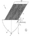
図1は、本発明の第1の態様による分離装置1を示す。分離装置は沈降セトラー2および収集容器3を備える。収集容器3は沈降セトラー2の下側に設置され、また、沈降セトラー2と流体連通している。収集容器3は受け入れチャンバー4を形成し、受け入れチャンバー4の底部には出口5が設けられる。沈降セトラー2のプレートは収集容器3まで及ばない。さらに、受け入れチャンバー4は入口開口部6を有する。図1はまた、液体または流体が収集容器3の中に導かれる入口チューブ61も示す。入口開口部6は収集容器3の直立した側壁41、例えば、収集容器3の上端より下にある特定の距離に位置する。すなわち、流入入口開口部6は沈降セトラー2の下端部22より下にある。本分野における液体または流体は、典型的には、細胞または細胞株を含有する懸濁液である。懸濁液は、例えば、発酵槽(示さず)から生じ、発酵槽から分離装置に供給される。従って、発酵槽から供給された懸濁液は、制御された下向きの方向に、沈降セトラーの下側にある収集容器に導入され、次いで、沈降セトラー2に向かって上方に、かつ沈降セトラー2を通って導かれる。「下向き」という用語は、流れが収集容器の出口に直接向かうのではなく、収集容器の出口の方向に向かうことを意味する。沈降セトラーの上方で懸濁液の透明な相は除去され、沈降した細胞は出口5において取り出される。
Aspects of illustration. 1 shows a
図1に示したように、収集容器3は流入偏向要素7を備えてよい。さらに大まかに言うと、偏向要素7は収集容器3の中に位置するように配置される。収集容器3および偏向要素7のサイズは、収集容器3内の流体の滞留時間が、偏向要素のない収集容器を有する分離装置と比較して短くなるように互いに対して適合される。偏向要素は、流入する粒子、細胞、および/または流体の直接的な相互作用を最小限にすると同時に、流体連通および/または粒子、例えば、細胞の沈降を悪く乱すことなく速い流速を可能にする。これは、滞留時間を短くするために必要である。図1によれば、流入偏向要素7は、入口開口部6の近くに、または入口開口部6に隣接して位置する。流入偏向要素7は、入口開口部6を通る液体または流体の流入を下向きに偏向するように形成および配置される。これは、偏向要素7によって引き起こされる流れの曲線を視覚化した矢印によって図1に示される。前述のように、受け入れチャンバー4への液体または流体の流入は、ある程度、重力によって、受け入れチャンバー4の底部に向かって流れる(破線の矢印によって図1に示した)。しかしながら、偏向要素7は、収集容器3の底部に向かう制御された方向に流入を偏向する。言い換えると、偏向要素7は、液体の流れが、重力によって導かれる自然の経路に沿って流れないようにし、液体の流れの方向を下向きに変えるように制御する。
As shown in FIG. 1, the
図1の受け入れチャンバー4の壁41はカップまたはボウルのように湾曲している。すなわち、直立した壁は平らでなく、受け入れチャンバーの底部に向かって水平断面積が減少するように湾曲を備える。例えば、受け入れチャンバー4は逆円錐もしくは切断された円錐の形状を有する、またはカップの形もしくはボウルの形をしている、すなわち、湾曲した内壁を有する。
The
最初に下向きに偏向された流入が沈降セトラー2に向かって上方にさらに導かれるように、偏向要素7の配置および形状ならびに受け入れチャンバー4の湾曲が互いに対して適合される。これは、沈降セトラー2に到達する流体の流れを示した矢印によって図1にも示された。従って、入口開口部6に隣接して、流入は最初に下向きに偏向される。次いで、流入は、受け入れチャンバー4の内壁41によってさらに下向きに導かれ、容器3の概して湾曲した形状に従い、上向きに、かつ沈降セトラー2に向かって導かれる。
The arrangement and shape of the deflecting
流入偏向要素7はバッフルプレートでもよい。バッフルプレート7は、第1の想像上の垂直面V1に対して傾斜して配置され、第1の想像上の垂直面V1は、入口開口部を通る流入方向軸を含む第2の想像上の垂直面V2と直角をなす。これは、示された想像上の平面以外は図1と同一の図3に示された。図3において、第2の想像上の垂直面V2は、この図の平面である。第1の想像上の垂直面V1は、この平面V2と直角をなして示される。示された態様において、バッフルプレート7は、水平線H1に沿った第1の想像上の垂直面V1と交差するような角度αで傾斜している。図3において、水平線H1は第2の面V2とも直角をなす。これは、第2の面V2と直角をなす水平線H1を示し、偏向要素7の上端部も示す図2において見ることができる。図1および図3の態様において、バッフルプレート7の傾斜αは沈降セトラー2の傾斜α'と同じである(図3を参照されたい)。
The
この態様において、流入入口開口部6も沈降セトラー2の下端部22の下側に位置する。
In this embodiment, the
図6に示した別の態様において、偏向プレート7'もまた第1の想像上の垂直面V1に対して傾斜して配置され、第1の想像上の垂直面V1は、入口開口部を通る流入方向軸を含む第2の想像上の垂直面V2と直角をなす。しかしながら、この態様において、偏向プレートは、水平線H2に沿った第2の想像上の垂直面V2と交差するように傾斜している。 In another embodiment shown in FIG. 6, the deflection plates 7 'are also disposed inclined with respect to the vertical plane V 1 of the first imaginary vertical plane V 1 of the on the first imagined, the inlet opening forming a second vertical plane V 2 at right angles with imaginary including inflow direction axis passing through the. However, in this embodiment, the deflection plate is inclined to intersect the second imaginary vertical plane V 2 along the horizontal line H 2 .
図1の態様において、バッフルプレート7は沈降セトラー2の下端21の伸長部として延長している。特に、バッフルプレート7は、入口開口部6に最も近い沈降セトラー2の下端部22にある受け入れチャンバー4まで及んでいる。従って、偏向要素は、収集容器まで達する沈降セトラーの外面の延長部を形成すると言うことができる。
In the embodiment of FIG. 1, the
または、バッフルプレート170は、入口開口部160上方の収集容器130の内壁と接続される。このような態様は図5において示される。図5において、湾曲した偏向プレート170が示されるが、水平線に対して傾斜している限り、まっすぐでもよい。この態様でも、流入入口開口部6は沈降セトラー2の下端部の下側に位置する。
Alternatively, the
または、バッフルプレート270は、入口開口部260の上方に隣接する収集容器230の内壁と接続される。すなわち、バッフルプレートは入口261の上半分の延長部である。このような態様を図8に示した。図8には、湾曲した偏向プレート270が示されたが、水平線に対して傾斜している限り、まっすぐでもよい。
Alternatively, the
本発明の任意の態様において、偏向要素は、入口開口部を通る流入方向軸を越えて下向きに伸びる程度まで受け入れチャンバーまで及ぶ。より好ましくは、液体の流入が偏向要素に到達し、実質的に水平に流れることができない、従って、単に偏向要素を通過できないことを確実なものにするために、偏向要素は、入口開口部の下端部22を越えて下向きに伸びる程度まで受け入れチャンバーまで及ぶ。 In any aspect of the invention, the deflection element extends to the receiving chamber to the extent that it extends downward beyond the inflow direction axis through the inlet opening. More preferably, to ensure that the inflow of liquid reaches the deflection element and cannot flow substantially horizontally, and therefore cannot simply pass through the deflection element, the deflection element is It extends to the receiving chamber to the extent that it extends downward beyond the lower end 22.
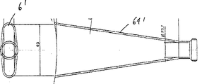
収集容器3の垂直高さは、好ましくは、400mm〜500mmの範囲、より好ましくは、約450mmである。その最大径または最高径は600mm〜700mmの範囲、好ましくは、約650mmでもよい。入口開口部の水平中心線または流入方向軸は、好ましくは、収集容器の上端部の約80mm〜90mm下側、より好ましくは、約88mm下側に位置する。バッフルプレートの長さは、好ましくは、150mm〜200mmの範囲にあり、より好ましくは、約180mmである。バッフルプレートの水平幅は、少なくとも、バッフルプレートの位置において、入口開口部から離れた投射された流れの幅と同じであるか、またはそれより大きい。
The vertical height of the
セトラープレートの長さは、600〜900mm、好ましくは、700〜800mmの範囲内でよく、より好ましくは、約720mmである。セトラープレートの幅は400mm〜500mmでもよく、好ましくは、約430mmである。セトラーの傾斜は、15〜60°、好ましくは、30〜45°、より好ましくは、30°でもよい。 The length of the settler plate may be in the range of 600-900 mm, preferably 700-800 mm, more preferably about 720 mm. The width of the settler plate may be 400 mm to 500 mm, preferably about 430 mm. The inclination of the settler may be 15 to 60 °, preferably 30 to 45 °, more preferably 30 °.
偏向プレートは450〜200mmの幅を有してもよく、好ましくは、その下端において約430mm、その上端において約215mmの幅を有する。偏向プレートの高さは130mm〜200mmでもよく、好ましくは、約130mmである。 The deflection plate may have a width of 450-200 mm, and preferably has a width of about 430 mm at its lower end and about 215 mm at its upper end. The height of the deflection plate may be between 130 mm and 200 mm, preferably about 130 mm.
入口開口部は、直径が、好ましくは、約80〜90mm(好ましくは、約85mm)および12〜20mm(好ましくは、約17mm)の楕円形状を有してもよい。 The inlet opening may have an elliptical shape with a diameter of preferably about 80-90 mm (preferably about 85 mm) and 12-20 mm (preferably about 17 mm).
さらなる態様によれば、分離装置1は、入口開口部6の上流において、または入口チューブ61の中に、流入の方向を制御し、流入の速度を小さくするための手段を備えてもよい。この手段は、例えば、当業者に公知のフローディストリビュータまたは流速のいかなる減速装置でもよい。この手段は、細胞が偏向プレートに衝突した時、負の加速度を小さくし、(図6に示した、下記の態様による流れと同様に)容器壁に沿った細胞懸濁液の流れを助ける。
According to a further aspect, the
沈降セトラー2は複数のプレート23を備え、複数のプレート23の間に複数の沈降チャンネルが形成される。沈降セトラーは、好ましくは、60〜70個のチャンネル、好ましくは、65個または66個のチャンネルを有する。
The settling
図4は入口開口部6'の一態様を示す。図4において見ることができるように、入口開口部は、円形でない形状、好ましくは、楕円形状を有する。図4は、入口開口部が収集容器の周囲に沿って伸びるような模式上面図である。このような円形でない入口開口部は、流速が低下するように流入の緩和を引き起こす。さらに、このような入口開口部を用いると、液体流入によって、流れを下向きに偏向するためにバッフルプレートの幅全体が用いられる。このような入口開口部によって流れの横断面が広がる。
FIG. 4 shows an embodiment of the
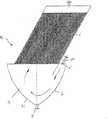
図7は、本発明の第2の態様による分離装置10の模式断面図を示す。図7では、図1と比較して分離装置の同じ成分が同じ符番で示される。
FIG. 7 shows a schematic cross-sectional view of the
この態様において、流入入口開口部6は、沈降セトラー2の下端部と同じ、分離装置の垂直高さレベルに位置する。
In this embodiment, the
本発明のこの態様において、流入入口開口部6'、すなわち、流入チューブ61'は、入口開口部6'を通る流体流入の方向が沈降セトラー2の方向または傾斜(α')と平行になるように配置される。
In this aspect of the invention, the inlet inlet opening 6 ′, ie the
または、流入入口開口部は、沈降セトラー2のチャンネルの方向と厳密に平行でなく、入口開口部6'を通る流入方向軸を含む想像上の垂直面(V2)において見た場合に、沈降セトラーの方向/傾斜から+/-10°それている。
Alternatively, the inlet inlet opening is not exactly parallel to the channel direction of the settling
従って、流入チューブ61'のこの配置は、収集容器3の底部に向かう方向に流入を導く。最初に下向きに偏向された流入が沈降セトラー2に向かって上方にさらに導かれるように、流入チューブ61'および入口開口部6'の配置および位置ならびに受け入れチャンバー4の湾曲は互いに対して適合される。これは、沈降セトラー2に到達する流体の流れを示した矢印によって図7にも示された。従って、最初に、流入は下向きに向けられる。次いで、流入は、受け入れチャンバー4の内壁41によってさらに下向きに導かれ、容器3の概して湾曲した形状に従い、次いで、上向きに、かつ沈降セトラー2に向かって導かれる。それにもかかわらず、望ましい方向に沿って流れをさらに導くために、第1の態様による(例えば、図3に示した)偏向要素を第2の態様に加えることができる。
Therefore, this arrangement of the
本発明は図面および前述の説明において詳細に例示および説明されたが、このような例示および説明は例示または例証であり、限定をするものではないとみなさなければならない。添付の特許請求の範囲の中で、当業者によって変化および変更が加えられ得ることが理解されるだろう。特に、本発明は、前記および下記の異なる態様からの特徴を任意に組み合わせた、さらなる態様を含む。 Although the invention has been illustrated and described in detail in the drawings and foregoing description, such illustration and description are to be considered illustrative or exemplary and not restrictive. It will be understood that changes and modifications may be made by those skilled in the art within the scope of the appended claims. In particular, the invention includes further embodiments, optionally combining features from the different embodiments described above and below.
さらに、添付の特許請求の範囲の中にある「含む(comprising)」という言葉は他の要素または工程を排除せず、不定冠詞「1つの(a)」または「1つの(an)」は複数を排除しない。単一のユニットが、添付の特許請求の範囲において引用された、いくつかの特徴の機能を果たしてもよい。特に、限定語または値に関連した、「本質的に」、「約(about)」、「約(approximately)」などの用語も、それぞれ、正確に属性を規定する、または正確に値を規定する。添付の特許請求の範囲の中にある、いかなる参照符号も、その範囲を限定するものと解釈してはならない。 Further, the word “comprising” in the appended claims does not exclude other elements or steps, and the indefinite article “a” or “an” is plural. Do not exclude. A single unit may fulfill the functions of several features recited in the appended claims. In particular, terms such as `` essentially '', `` about '', `` approximately '', etc., related to a qualifier or value, define the attribute exactly or define the value exactly, respectively. . Any reference signs in the claims should not be construed as limiting the scope.
以下は、本発明の非限定的な実施例およびその実用的な用途を示す。 The following shows non-limiting examples of the present invention and their practical applications.
実施例1:以下の例示された細胞培養および細胞分離の材料および方法
1.1 細胞株
実施例において使用した細胞株は、ヒトIgGクラスの治療抗体を産生する組換えCHO DG44細胞株であった。
Example 1: Materials and methods for cell culture and cell separation exemplified below
1.1 Cell line The cell line used in the examples was a recombinant CHO DG44 cell line producing a therapeutic antibody of the human IgG class.
1.2 緩衝液/培地
泡を防ぐために、Antifoam Dow Emulsion; Biesterfeld Spezialchemie GmbHを使用した。pHを調節するために、1mol/L炭酸ナトリウムを使用した。
1.2 Buffer / medium Antifoam Dow Emulsion; Biesterfeld Spezialchemie GmbH was used to prevent foaming. 1 mol / L sodium carbonate was used to adjust the pH.
1.3 培養
1.3.1 実験システム
CHO細胞株(前記を参照されたい)をフェドバッチ培養で培養した。シードトレインは振盪フラスコからの接種から開始し、それぞれの連続培養の培養体積(20Lから3,000L)が漸増する4回連続したシードトレイン培養および10,0000L主発酵からなった(図9を参照されたい)。
1.3 Culture
1.3.1 Experimental system
The CHO cell line (see above) was cultured in fed-batch culture. The seed train started with inoculation from shake flasks and consisted of 4 consecutive seed train cultures and 10,0000L main fermentation with increasing culture volumes (20L to 3,000L) for each continuous culture (see Figure 9). Wanna).
温度を、全ての培養においてダブル加熱ジャケットによって自動調節する。PH調節を、蠕動ポンプを用いたアルカリ性溶液(塩基)添加によって、ならびにマスフロー(mass flow)を介した気体CO2の導入によって行う。溶存酸素を、空気および窒素ならびに圧力および攪拌速度によって自動調節する。 The temperature is automatically adjusted with a double heating jacket in all cultures. PH adjustment is performed by addition of alkaline solution (base) using a peristaltic pump and by introduction of gaseous CO 2 via mass flow. Dissolved oxygen is automatically adjusted by air and nitrogen and pressure and stirring rate.
1.3.2 接種培養
培養は、振盪フラスコの中で段階的に体積を2Lまで増やして行われる。培養パラメータは、約37℃、相対湿度>70%での空気および5%CO2の供給であった。振盪速度として125rpmを使用した。2Lフラスコ中で望ましい細胞密度に達したら、20Lバイオリアクターに接種した。
1.3.2 Inoculation culture Cultivation is carried out in a shake flask in steps of increasing the volume up to 2L. Culture parameters were a supply of air and 5% CO 2 at approximately 37 ° C. and relative humidity > 70%. 125 rpm was used as the shaking speed. When the desired cell density was reached in the 2L flask, the 20L bioreactor was inoculated.
1.3.3 400Lまでのシードトレイン
N-4工程(20L)を、選択圧および3%のリアクター体積(RV)供給/日を用いて行った。N-3からN-1の工程において、細胞を選択圧なしで、これも3%RV供給/日で増殖させた。温度を37℃で調節した。pH値を約pH7で調節した。加圧空気を使用することによって、pO2を約30%で調節した。シードトレイン(工程N-4からN-2)の間に試料を毎日採取し、細胞濃度、pH、pCO2、重量オスモル濃度、および生成物濃度を求めた。分析法については、実施例1.4を参照されたい。シードおよび接種トレインを含む小規模で開始する産生プロセスを実施した。n-1スケール(例えば、図10を参照されたい)では、産生用バイオリアクターNの高接種細胞密度を実現するために、日常的に用いられるバッチ操作を、高細胞密度を生じる大規模灌流に置き換えた。産生スケールにおいて低接種細胞密度につながる非灌流形式を使用する確立したプロセスを、高細胞密度につながる灌流要素を用いた改良プロセスと比較した。前記の分離装置を用いたプロセスの結果、操作、および比較の詳細を以下に示した。
1.3.3 Seed train up to 400L
Step N-4 (20 L) was performed using selective pressure and 3% reactor volume (RV) feed / day. In steps N-3 to N-1, cells were grown without selective pressure, also at 3% RV feed / day. The temperature was adjusted at 37 ° C. The pH value was adjusted at about pH7. The pO 2 was adjusted at about 30% by using pressurized air. Samples were taken daily during the seed train (steps N-4 to N-2) to determine cell concentration, pH, pCO 2 , osmolality, and product concentration. For analysis methods, see Example 1.4. A small-scale production process including seed and inoculation train was performed. On the n-1 scale (see, e.g., Figure 10), to achieve the high inoculum cell density of the production bioreactor N, routinely used batch operations are scaled to large-scale perfusion resulting in high cell density. Replaced. An established process using a non-perfusion format leading to low seeded cell density at the production scale was compared with an improved process using perfusion elements leading to high cell density. Details of the results, operations and comparisons of the processes using the separation device described above are given below.
1.3.4 3,000Lスケールでの灌流プロセス
灌流培養のないプロセスと比較して5日間の灌流で高細胞密度に到達することを目的とした灌流培養として、N-1工程を実施した(例えば、図10を参照されたい)。
1.3.4 Perfusion process at 3,000L scale The N-1 step was performed as a perfusion culture aimed at reaching high cell density with 5 days of perfusion compared to the process without perfusion culture (e.g. (See 10).
N-2工程まで、確立したプロセスに従ってシードトレインを実施した。N-1培養のみ変更を施した。 The seed train was carried out according to the established process up to Step N-2. Only N-1 culture was changed.
全灌流システムは、3,000Lバイオリアクター、バイブレータおよび連結したスパイラル直交流式熱交換器を備える本明細書において報告された分離装置、供給物添加(モデル624Di)、灌流液(perfundate)ドレン(モデル624Di)、および循環(モデル620U)のための3つの蠕動ポンプ(Watson Marlow Inc.)、灌流培地用および廃棄物(灌流液)用の2つの培地タンク(それぞれ体積3,000L)からなった。試料装置は灌流液ラインおよびバイオリアクターに設けられた。 The total perfusion system consists of a separation device, feed addition (model 624Di), perfudate drain (model 624Di) reported here comprising a 3,000L bioreactor, vibrator and connected spiral cross flow heat exchanger. ), And three peristaltic pumps (Watson Marlow Inc.) for circulation (model 620U), two medium tanks (3,000 L each) for perfusion medium and waste (perfusate). Sample devices were installed in the perfusate line and bioreactor.
分離装置を用いて、培養上清から細胞を分離し、バイオリアクターに戻して生細胞を再利用した。 Cells were separated from the culture supernatant using a separation device, returned to the bioreactor, and the living cells were reused.
それぞれ5日間、2回連続して灌流発酵を行った。1回目の3,000L操作を1回目のバイオリアクターの播種密度の4倍の播種密度で分割し、産生用バイオリアクターに同時接種することによって、2回目の灌流発酵に接種した(図10)。
Perfusion fermentation was performed twice consecutively for 5 days each. The first 3,000 L operation was split at a seeding
最初に、細胞をバッチモードで1〜2日間増殖させ、次いで、前記で概説したように、第1の灌流操作のために灌流を開始した。灌流中、始めに3時間ごとにバイオリアクターからの試料および灌流液を採取した。2日目の後に、試料を6時間ごとに採取したが、供給体積流量を3時間ごとに調節した。 Initially, cells were grown in batch mode for 1-2 days, and then perfusion was initiated for the first perfusion procedure as outlined above. During the perfusion, samples and perfusate from the bioreactor were initially collected every 3 hours. Samples were taken every 6 hours after the second day, but the feed volume flow rate was adjusted every 3 hours.
産生培養中に試料も毎日採取した。 Samples were also taken daily during production culture.
1.3.5 可変培養体積での培養
N-1シードトレイン培養から以後のバイオリアクターへの接種を、異なるスケール(2Lから400Lまで)のシステムにおいて異なるパラメータ(表1を参照されたい)、例えば、本実験のメインターゲットである異なる細胞密度を用いて行った。他のパラメータを細胞密度の増加に合わせた。1つの条件は、本明細書において報告された灌流モードと比較して細胞密度の低い確立した参照プロセスを表している。細胞は、高細胞密度で接種された後に誘導期も制限も示さない。それによって、全発酵時間(シードトレインおよび主培養)を短くすることができ、それによって、同等の収量をシングルバッチで得ることができる。
1.3.5 Culture with variable culture volume
Inoculation of N-1 seed train cultures into subsequent bioreactors for different parameters (see Table 1) in different scale (2L to 400L) systems, for example, different cell densities that are the main target of this experiment It was performed using. Other parameters were adjusted to increase cell density. One condition represents an established reference process with low cell density compared to the perfusion mode reported herein. The cells show no induction phase or restriction after being seeded at high cell density. Thereby, the total fermentation time (seed train and main culture) can be shortened, whereby an equivalent yield can be obtained in a single batch.
灌流培養を用いることによって利用可能になる、利用可能な高い接種細胞密度が細胞の増殖または品質に影響を及ぼすかどうか確かめるために、異なるパラメータを使用した。 Different parameters were used to ascertain whether the high available seeded cell density available by using perfusion cultures affects cell growth or quality.
培地および供給原料は全ての培養において同じであった。培養中の個々の事象のタイムスケジュール、例えば、供給の開始時間を、培養体積および参照産生プロセスに基づく開始細胞密度に従って調整した。例えば、セトラー/灌流のないプロセス(参照プロセス)と比較して接種細胞密度が増えているのであれば、時点をさらに早い時点に変えた。 The medium and feed were the same in all cultures. The time schedule of individual events in the culture, for example the start time of the feed, was adjusted according to the culture volume and the starting cell density based on the reference production process. For example, the time point was changed to an earlier time point if the inoculated cell density was increased compared to the process without the settler / perfusion (reference process).
増殖期の間に温度を約37℃で調節し、pH値を約pH7に調節し、pO2を、加圧空気を用いて30%に設定した。
During the growth phase, the temperature was adjusted to about 37 ° C., the pH value was adjusted to about
(表1)培養の概要

1.4 分析方法
1.4.1 細胞密度
細胞密度は、CEDEX HiRes自動細胞カウンター(Roche Innovatis, Bielefeld)を用いて製造業者の説明書に従ってトリパンブルー法によって求めた。細胞密度を標準的な接種密度の16倍超にすることによって、細胞培養液をPBS-pufferで1:5に希釈した。測定された全ての細胞に対する生細胞の比が生存率を示した。
1.4 Analysis method
1.4.1 Cell density Cell density was determined by the trypan blue method using a CEDEX HiRes automated cell counter (Roche Innovatis, Bielefeld) according to the manufacturer's instructions. The cell culture was diluted 1: 5 with PBS-puffer by making the cell density more than 16 times the standard inoculation density. The ratio of viable cells to all measured cells indicated viability.
1.4.2 基質濃度
培養物中のグルコース、乳酸、グルタミン、およびアンモニウムの濃度は、BIOPROFILE flex analyzer(Nova Biomedicals, Waltham)を用いて求めた。この測定法はバイオセンサーまたはイオン選択性電極に基づく。
1.4.2 Substrate concentration The concentrations of glucose, lactic acid, glutamine and ammonium in the culture were determined using the BIOPROFILE flex analyzer (Nova Biomedicals, Waltham). This measurement method is based on biosensors or ion selective electrodes.
1.4.3 pHおよびpCO2の測定
バイオリアクター中のpH値は、pHメーター(WTW, Inolab)によって毎日、外部より管理した。pCO2値は、AVL Compact 3血液ガス分析器(Roche, Switzerland)に従って毎日チェックした。
1.4.3 Measurement of pH and pCO 2 The pH value in the bioreactor was externally controlled daily by a pH meter (WTW, Inolab). pCO 2 values were checked daily according to the
1.4.4 重量オスモル濃度
灌流中の浸透圧および供給の変化をチェックするために、重量オスモル濃度を毎日測定した。Osmomat 030(Gonotec, Berlin, Germany)を使用した。測定法は、純水および溶液の凝固点の比較測定に基づく。水の凝固点は0℃であるが、食塩濃度1mOsmol/kgの溶液の凝固点は-1.858℃である。
1.4.4 Osmolality Osmolality was measured daily to check for changes in osmolality and supply during perfusion. Osmomat 030 (Gonotec, Berlin, Germany) was used. The measurement method is based on a comparative measurement of the freezing point of pure water and solution. The freezing point of water is 0 ° C, but the freezing point of a solution with a salt concentration of 1 mOsmol / kg is -1.858 ° C.
1.4.5 乳酸デヒドロゲナーゼ活性
乳酸デヒドロゲナーゼ活性(LDH)は発酵中の細胞曝露と関連がある。ダメージを受けた細胞は生細胞より多くのLDHを培地に送り出す。測定法はマイクロタイタープレート上での酵素アッセイに基づく。LDHが存在すると、NADHはNAD+に酸化され、ピルビン酸が乳酸に還元される。NADHの減少速度は340nmでの吸光度によって測定される。
1.4.5 Lactate dehydrogenase activity Lactate dehydrogenase activity (LDH) is associated with cell exposure during fermentation. Damaged cells send more LDH to the medium than live cells. The assay is based on an enzyme assay on a microtiter plate. In the presence of LDH, NADH is oxidized to NAD + and pyruvate is reduced to lactic acid. The rate of decrease of NADH is measured by absorbance at 340 nm.
1.5 抗体分析
抗体価を、Poros Aアフィニティカラムを用いた高速液体クロマトグラフィー(HPLC)によって定量した。
1.5 Antibody analysis Antibody titers were quantified by high performance liquid chromatography (HPLC) using a Poros A affinity column.
実施例2:シードトレイン培養
1.1 400Lまでのシードトレイン
実施例1において概説したように、これを実施した。接種細胞密度に達したら、20L〜400Lのバイオリアクターにおける供給は規定の体積流速から開始した。20Lバイオリアクターを1回分割し、バックアップの目的で80Lバイオリアクターに2回接種した。
Example 2: Seed train culture
1.1 Seed train up to 400 L This was done as outlined in Example 1. Once the seeded cell density was reached, the feed in the 20L-400L bioreactor was started from a defined volume flow rate. The 20L bioreactor was divided once and inoculated twice into the 80L bioreactor for backup purposes.
1.2 分離装置の設計
分離装置が大規模なために、装置に適用する前に培養物を冷却するのに十分な熱交換器も組み立てなければならなかった。細胞に対するストレスおよび圧力を小さくするために、スパイラル直交流式熱交換器(MCE AG, Germany)を使用した。
1.2 Separation device design Due to the large separation device, enough heat exchangers had to be assembled to cool the culture prior to application to the device. A spiral cross flow heat exchanger (MCE AG, Germany) was used to reduce stress and pressure on the cells.
内部では、セトラーは65個の着脱可能なステンレス鋼プレートからなった。全沈降面積を、7m2または10m2、例えば、8m2に設定した。セトラーを水平線から60°の角度で傾斜させた。傾斜は必要に応じて回転ホイールによって変えることができる。電磁バイブレータを取り付けた。電磁バイブレータを15分ごとに10〜20秒間、自動的に作動させた。角度の調整および振動の間隔は、細胞が効率的に再利用されることを確実なものにした。 Inside, the settler consisted of 65 removable stainless steel plates. The total sedimentation area was set to 7 m 2 or 10 m 2 , for example 8 m 2 . The settler was tilted at an angle of 60 ° from the horizon. The tilt can be changed by a rotating wheel as required. An electromagnetic vibrator was attached. The electromagnetic vibrator was automatically activated every 15 minutes for 10-20 seconds. The angle adjustment and the vibration interval ensured that the cells were efficiently recycled.
使用前に、機器全体を無菌化または滅菌し(CIPおよびSIP)、微生物が存在しないかどうか試験した。標準的な操作手順および無菌試験に対応する機器の設計資格(DQ)、設置資格(IQ)、以下の操作資格(OQ)、および性能資格(PQ)は異常を示さなかった。 Prior to use, the entire device was sterilized or sterilized (CIP and SIP) and tested for the presence of microorganisms. The equipment design qualification (DQ), installation qualification (IQ), the following operational qualification (OQ), and performance qualification (PQ) corresponding to standard operating procedures and sterility tests showed no abnormalities.
1.3 灌流
1.3.1 手順
培養物の灌流を開始するために、バイオリアクターの細胞培養流体をディップチューブに通して熱交換器にポンプで入れた。熱交換器にポンプは培養物を10〜15℃に冷却した。これは、バイオリアクター外にある間の、すなわち、制御されていない条件下の間の細胞代謝の低下として役立った。
1.3 Perfusion
1.3.1 Procedure To initiate perfusion of the culture, the bioreactor cell culture fluid was pumped through the dip tube into the heat exchanger. A pump to the heat exchanger cooled the culture to 10-15 ° C. This served as a reduction in cellular metabolism while outside the bioreactor, ie during uncontrolled conditions.
循環ポンプは、約390L/hの体積流速で培養物の流速を一定に制御した。総ループ体積は約200Lであった。灌流供給速度はバイオリアクター内での細胞密度によって調節された。 The circulation pump controlled the culture flow rate constant at a volumetric flow rate of about 390 L / h. The total loop volume was about 200L. The perfusion feed rate was regulated by the cell density in the bioreactor.
1.3.2 細胞増殖
2回の連続した灌流(P1およびP2)の間の生細胞密度(VCD)および細胞生存率の比較を図11に示した。どちらの場合も、100%超(約130%)の細胞密度に達した。<85%の生存率のアンダーカット(undercut)は行われなかった。
1.3.2 Cell proliferation
A comparison of viable cell density (VCD) and cell viability between two successive perfusions (P1 and P2) is shown in FIG. In both cases, cell densities of over 100% (about 130%) were reached. No undercut with a survival rate of <85% was made.
1.3.3 細胞捕捉(グレード/効率)
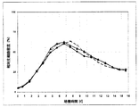
本明細書において概説されたように、分離装置は上清からの細胞の分離において良好に機能した。分離効率および灌流体積を図12に示した。分離効率(捕捉レベル)は期間全体にわたって>0.9=90%であった。捕捉が<95%に低下したら、振動時間を延長した。
1.3.3 Cell capture (grade / efficiency)
As outlined herein, the separation device performed well in separating cells from the supernatant. The separation efficiency and perfusion volume are shown in FIG. The separation efficiency (capture level) was > 0.9 = 90% over the entire period. When capture decreased to <95%, the vibration time was extended.
細胞増殖を支持するには、バイオリアクター体積の0.9倍の最大灌流供給回転率、すなわち2,400L/d(システム全体の3,000L-循環中の200L流体に相当する)で十分であった。どちらの灌流の分離効率も95%超のままであった。これらの結果は、セトラー角度またはポンプを調整することによって灌流を最適化することなく得られた。 A maximum perfusion feed rotation rate of 0.9 times the bioreactor volume, 2,400 L / d (corresponding to 3,000 L of the entire system—200 L fluid in circulation) was sufficient to support cell growth. The separation efficiency of both perfusions remained above 95%. These results were obtained without optimizing perfusion by adjusting the settler angle or pump.
図12から分かるように、どちらの灌流試験も、少なくとも95%の同等の細胞捕捉(図12の上の部分)および同等の灌流速度の増加を示す。P1はフェドバッチの2日後に灌流を開始したのに対して、P2はフェドバッチのわずか1日後に灌流を開始したことに留意しなければならない。従って、P2の曲線はP1の曲線より早く開始する。 As can be seen from FIG. 12, both perfusion studies show at least 95% equivalent cell capture (upper part of FIG. 12) and an equivalent increase in perfusion rate. It should be noted that P1 began to perfuse 2 days after the fed-batch, whereas P2 began to perfuse only 1 day after the fed-batch. Therefore, the curve for P2 starts earlier than the curve for P1.
灌流速度の最適化は、より良い細胞還流のためにはセトラー角度を調整することによって、または高い細胞密度のためには供給の最適化によって実現することができる。 Optimization of the perfusion rate can be achieved by adjusting the settler angle for better cell reflux or by optimization of the feed for high cell density.
1.4 培養
1.4.1 細胞増殖および生存率
例示的な発酵番号1、3、4、および5(前記の表1を参照されたい)を産生培養と比較した。
1.4 Culture
1.4.1 Cell growth and viability
発酵に異なる細胞密度で接種した。それに応じて、供給開始時間を調整した。10,000L培養(2L体積と100%の接種細胞密度を用いた試験3)と比較して同等の生成物濃度を短期間で得るために、接種細胞密度を333%(400L体積を用いた試験1および2L体積を用いた試験4)ならびに666%(2L体積を用いた試験5)まで増やした。産生プロセスの対照として、100%の接種細胞密度による2つの発酵も行った。
The fermentation was inoculated at different cell densities. The supply start time was adjusted accordingly. To obtain an equivalent product concentration in a short period of time compared to a 10,000 L culture (
シードトレインのN-1発酵において用いられる灌流は以後の発酵において細胞の細胞増殖に影響を及ぼさない。すなわち、誘導期を特定できなかった。 Perfusion used in N-1 fermentation of the seed train does not affect cell growth in subsequent fermentation. That is, the induction period could not be specified.
図13は、平均10,000L発酵と比較した2L培養の細胞増殖を示す。 FIG. 13 shows cell growth of 2 L cultures compared to an average 10,000 L fermentation.
確立した産生プロセスと、セトラー操作から得られた高い接種細胞密度とを比較した(図14を参照されたい)。細胞の生存率、細胞増殖、代謝の違いは観察されなかった。灌流は細胞の増殖および生存率に影響を及ぼさなかった。 The established production process was compared to the high inoculated cell density obtained from the Settler operation (see Figure 14). No differences in cell viability, cell proliferation, or metabolism were observed. Perfusion did not affect cell growth and viability.
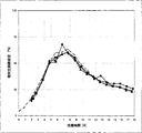
図15/16は、参照産生プロセス(破線)と比較した、333%の接種細胞密度を用いた3つの発酵(1x400Lおよび2x2L)の生細胞密度および生存率を示す。400Lの体積および2Lの体積では約5日目で既に最大細胞密度に達したのに対して、産生プロセスの体積では7日目に最大細胞密度に達したので、高接種細胞密度によって培養時間は約2日短くなった。また、高接種細胞密度は指数細胞増殖の間に誘導期を引き起こさなかった。 Figure 15/16 shows the viable cell density and viability of three fermentations (1x400L and 2x2L) using an inoculated cell density of 333% compared to the reference production process (dashed line). In the 400L and 2L volumes, the maximum cell density was already reached in about 5 days, whereas in the production process volume, the maximum cell density was reached on the 7th day, so the culture time was increased due to the high seeding cell density. About 2 days shorter. Also, high seeded cell density did not cause an induction phase during exponential cell growth.
図17および図18において比較した場合、培養の比較性を示すために、生細胞密度および生存率の曲線は約+2日シフトした。これは、本明細書において報告された分離装置の使用が細胞の増殖特性に影響を及ぼさないという事実の証拠を提供する。 When compared in FIG. 17 and FIG. 18, the live cell density and viability curves were shifted by about +2 days to show culture comparability. This provides evidence of the fact that the use of the separation device reported herein does not affect the growth characteristics of the cells.
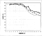
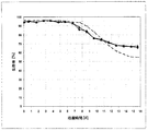
図19/20および図21/22に示したように、666%の接種細胞密度を用いて類似した結果が得られた。この図の中では、666%の接種細胞密度を用いた2つの2L培養の細胞増殖および生存率を示した。図から分かるように、培養の4日後には既に最大細胞密度に達し、これによりプロセス時間は約3日、短くなった(図19/20の曲線が約+3日シフトした図21/22に示した)。従って、666%の接種細胞密度では、分離装置は後の培養において細胞増殖および生存率に対して影響を及ぼさない。 Similar results were obtained using an inoculated cell density of 666%, as shown in FIGS. 19/20 and 21/22. In this figure, the cell growth and viability of two 2L cultures using an inoculated cell density of 666% is shown. As can be seen, the maximum cell density has already been reached after 4 days of culture, which shortened the process time by about 3 days (the curve in Figure 19/20 has shifted to +21 days in Figure 21/22). Indicated). Thus, at an inoculated cell density of 666%, the separation device has no effect on cell growth and viability in subsequent cultures.
666%の接種細胞密度を用いた細胞増殖の誘導期は観察されなかった。濃縮した細胞懸濁液を得るためにセトラーを用いて666%の高細胞密度で接種することによって、細胞増殖の制限も阻害も認めることはできなかった。装置およびこの機器の悪影響は観察されなかった。 No induction phase of cell growth using an inoculated cell density of 666% was observed. By inoculating at a high cell density of 666% with a settler to obtain a concentrated cell suspension, no cell growth limitation or inhibition could be observed. No adverse effects of the device and this equipment were observed.
1.4.2 抗体の産生
100%の接種細胞密度を用いた2L培養の培養時間にわたる生成物濃度を図28に示した。高接種曲線の比較から、高接種細胞密度で本明細書において報告された分離装置を使用することによって、プロセス時間全体を4〜5日、短縮できることがはっきりと分かる。
1.4.2 Antibody production
The product concentration over the incubation time of the 2L culture with 100% inoculated cell density is shown in FIG. A comparison of the high inoculation curves clearly shows that the overall process time can be reduced by 4-5 days by using the separation device reported herein at high inoculation cell density.
従って、N-1シードトレイン発酵において本明細書において報告された分離装置を用いた前記のセクションにおいて概説したように、主培養に高細胞密度で接種することができる。さらに、細胞はN-1シードトレイン発酵において高細胞密度まで増殖するが、主培養への接種後に誘導期は観察することができない。細胞はすぐに指数増殖し始める。それによって、N-1シードトレイン発酵において分離装置を使用しない参照産生発酵と比較した時に、培養中のさらに早い時点で細胞密度および生成物濃度に関する対応する値に達した。細胞培養の成績および生成物の力価は有意差を示さず、操作時間を全体的に、接種細胞密度に応じて、それぞれ、少なくとも2日または少なくとも4日、短縮することができる。一例として、このプロセスを使用すると、産生時間を25%短縮することができる。 Thus, the main culture can be seeded at high cell density as outlined in the previous section using the separation apparatus reported herein in N-1 seed train fermentation. Furthermore, the cells grow to high cell density in N-1 seed train fermentation, but the induction phase cannot be observed after inoculation into the main culture. The cells begin to grow exponentially immediately. Thereby, corresponding values for cell density and product concentration were reached at an earlier time in culture when compared to a reference production fermentation without a separator in N-1 seed train fermentation. Cell culture performance and product titers show no significant differences, and the overall operating time can be shortened by at least 2 days or at least 4 days, respectively, depending on the inoculated cell density. As an example, this process can reduce production time by 25%.
2. 結果
本発明は、新規の沈降装置、特に、細胞培養および細胞分離における大規模使用量(例えば、2,000L/日〜3,000L/日のレベル)に適した新規の沈降装置に関する。
2. Results The present invention relates to a novel sedimentation device, and more particularly to a novel sedimentation device suitable for large-scale use in cell culture and cell separation (for example, a level of 2,000 L / day to 3,000 L / day).
N-1工程のシードトレインにおける高細胞密度に関して、参照プロセス(確立した産生プロセス)と比較してシードトレイン発酵における分離装置を使用した主培養の曲線を2〜4日短縮することができるという事実に加えて、シードトレイン発酵において分離装置を使用した主培養とシードトレイン発酵において分離装置を使用していない主培養との間で細胞増殖を良好に比較することができた。 The fact that the main culture curve using the separator in seed train fermentation can be shortened by 2-4 days compared to the reference process (established production process) for high cell density in the N-1 step seed train In addition, cell growth was successfully compared between the main culture using the separator in the seed train fermentation and the main culture not using the separator in the seed train fermentation.
装置は細胞培養に影響を及ぼさず、これによって高い捕捉率が得られた。 The device had no effect on cell culture, which resulted in a high capture rate.
本発明の要点は、本発明の装置を用いて、高い時間空間収率(time-space yield)のために高接種細胞密度を用いることによって、次に続く産生培養(N工程)において同等の細胞増殖(誘導期なし)および安定した生成物量を提供することである。 The main point of the present invention is that by using the apparatus of the present invention, a high inoculum cell density for high time-space yield, the same cell in the subsequent production culture (N step). To provide growth (no induction period) and a stable amount of product.
本発明の装置を用いて得られた細胞懸濁液による接種後に、異なる接種細胞密度は全て誘導期または阻害を示さなかった。 After inoculation with the cell suspension obtained using the device of the present invention, the different inoculated cell densities did not show any induction phase or inhibition.
前記をまとめると、本明細書において報告された分離装置を使用することによって、生成物濃度に悪影響を及ぼすことなく、必要とされる主発酵時間を少なくとも約2〜4日、短縮することが可能である。従って、1回の産生作業(campaign)、すなわち、シードトレイン発酵および主発酵に必要な時間を全体的に短縮することによって、同じ時間で、例えば、1年で、さらに多くの作業を行うことができる。すなわち、産生施設の拡大、すなわち、バイオリアクター体積の拡大を避けることができる。 In summary, the required main fermentation time can be reduced by at least about 2-4 days without adversely affecting the product concentration by using the separation apparatus reported herein. It is. Therefore, more work can be done in the same time, for example in one year, by reducing the overall time required for one campaign, i.e. seed train fermentation and main fermentation. it can. That is, the expansion of the production facility, that is, the expansion of the bioreactor volume can be avoided.
Claims (16)
該分離装置(1)は、
複数のチャンネルを有する沈降セトラー(2);および
沈降セトラー(2)の下側に設置されかつ沈降セトラー(2)と流体連通している収集容器(3)であって、受け入れチャンバー(4)の底部にあるかまたは該チャンバー底部に隣接する出口(5)を有しかつ出口(5)の上に流入入口開口部(6)を有する受け入れチャンバー(4)を形成する、収集容器(3)
を備え、ここで、
流入入口開口部(6)は、沈降セトラー(2)の下端部(22)と同じ、分離装置(1)の垂直高さレベルに位置するか、または沈降セトラー(2)の下端部(22)よりも下に位置し、
収集容器(3)は、入口開口部(6)を通過した後に受け入れチャンバー(4)内の流体流入の流れ方向が沈降セトラー(2)の該チャンネルの方向と実質的に同一直線上になるように配置され、かつ、
収集容器(3)が流入偏向要素(7)を備える、
使用。 Use of the separation device (1) in a seed train system comprising a first fermentor located upstream of the separation device (1) and at least a second fermenter located downstream of the separation device (1). ,
The separation device (1)
A settling settler (2) having a plurality of channels; and a collection vessel (3) installed underneath the settling settler (2) and in fluid communication with the settling settler (2), comprising a receiving chamber (4) A collection vessel (3) having an outlet (5) at or adjacent to the bottom of the chamber and forming a receiving chamber (4) having an inlet inlet opening (6) above the outlet (5)
Bei For example, here,
The inlet opening (6) is located at the same vertical height level of the separating device (1) as the lower end (22) of the settling settler (2) or the lower end (22) of the settling settler (2) Located below,
The collection container (3) is arranged so that the flow direction of the fluid inflow in the receiving chamber (4) is substantially collinear with the direction of the channel of the settling settler (2) after passing through the inlet opening (6). And
The collection container (3) comprises an inflow deflection element (7),
Use .
Applications Claiming Priority (2)
| Application Number | Priority Date | Filing Date | Title |
|---|---|---|---|
| EP11151110.1 | 2011-01-17 | ||
| EP11151110 | 2011-01-17 |
Related Parent Applications (1)
| Application Number | Title | Priority Date | Filing Date |
|---|---|---|---|
| JP2013548851A Division JP5995871B2 (en) | 2011-01-17 | 2012-01-13 | Separation device and use thereof |
Publications (2)
| Publication Number | Publication Date |
|---|---|
| JP2017006139A JP2017006139A (en) | 2017-01-12 |
| JP6194080B2 true JP6194080B2 (en) | 2017-09-06 |
Family
ID=44168237
Family Applications (2)
| Application Number | Title | Priority Date | Filing Date |
|---|---|---|---|
| JP2013548851A Active JP5995871B2 (en) | 2011-01-17 | 2012-01-13 | Separation device and use thereof |
| JP2016162526A Active JP6194080B2 (en) | 2011-01-17 | 2016-08-23 | Separation device and use thereof |
Family Applications Before (1)
| Application Number | Title | Priority Date | Filing Date |
|---|---|---|---|
| JP2013548851A Active JP5995871B2 (en) | 2011-01-17 | 2012-01-13 | Separation device and use thereof |
Country Status (9)
| Country | Link |
|---|---|
| US (4) | US20140057344A1 (en) |
| EP (2) | EP2665806B1 (en) |
| JP (2) | JP5995871B2 (en) |
| ES (1) | ES2890412T3 (en) |
| HR (1) | HRP20211494T1 (en) |
| PL (1) | PL2665806T3 (en) |
| SG (1) | SG191745A1 (en) |
| SI (1) | SI2665806T1 (en) |
| WO (1) | WO2012098055A1 (en) |
Families Citing this family (10)
| Publication number | Priority date | Publication date | Assignee | Title |
|---|---|---|---|---|
| EP2665806B1 (en) | 2011-01-17 | 2021-07-28 | F. Hoffmann-La Roche AG | Separation apparatus |
| TW202204596A (en) | 2014-06-06 | 2022-02-01 | 美商健臻公司 | Perfusion culturing methods and uses thereof |
| TW202246486A (en) | 2014-06-09 | 2022-12-01 | 美商健臻公司 | Seed train processes and uses thereof |
| US9944894B2 (en) * | 2015-01-16 | 2018-04-17 | General Electric Company | Pluripotent stem cell expansion and passage using a rocking platform bioreactor |
| WO2019103976A1 (en) * | 2017-11-22 | 2019-05-31 | Culture Biosciences, Inc. | Fermentation automation workcell |
| EP3781281B1 (en) * | 2018-04-18 | 2024-02-28 | Sudhin Biopharma | Particle settling devices |
| EP3561038A1 (en) * | 2018-04-24 | 2019-10-30 | Bayer AG | Cell separator |
| CN110935207B (en) * | 2019-12-13 | 2020-10-09 | 安徽理工大学 | Compact rake-free concentration device |
| IL296581A (en) | 2020-03-19 | 2022-11-01 | Sudhin Biopharma | Particle settling devices |
| US20220154127A1 (en) * | 2020-11-18 | 2022-05-19 | Global Life Sciences Solutions Usa Llc | System and method for aseptic sampling and fluid addition |
Family Cites Families (25)
| Publication number | Priority date | Publication date | Assignee | Title |
|---|---|---|---|---|
| US2967107A (en) * | 1957-03-04 | 1961-01-03 | John Labott Ltd | Continuous fermentation process |
| US3385439A (en) * | 1966-06-07 | 1968-05-28 | Niels B. Bach | Sedimentation method and apparatus |
| SE330151B (en) * | 1968-09-20 | 1970-11-09 | Nordstjernan Rederi Ab | |
| DE2139521B2 (en) * | 1971-08-06 | 1975-03-27 | Sybron Corp., Rochester, N.Y. (V.St.A.) | Inclined clarifier |
| US3898162A (en) * | 1973-08-20 | 1975-08-05 | Andrew Carlson & Sons Inc | Septic tanks |
| US3897676A (en) * | 1973-09-10 | 1975-08-05 | Hercules Membrino | Opening device for thermoplastic bags |
| US4123365A (en) | 1974-08-14 | 1978-10-31 | Ballast-Nedam Groep N.V. | Oil-water separator |
| NL7800180A (en) | 1978-01-06 | 1979-07-10 | Ballast Nedam Groep Nv | DEVICE FOR THE SEPARATION OF WATER AND SUBSTANCES THEREOF. |
| US4184954A (en) * | 1979-03-23 | 1980-01-22 | Peterson Albert C | Sedimentation device and method for purifying waste water |
| BE888016A (en) | 1981-03-19 | 1981-09-21 | Acec | REACTION CONTAINER FOR LIQUID REAGENT |
| US4814278A (en) * | 1985-02-05 | 1989-03-21 | Teijin Limited | Culture apparatus and method |
| NL8501767A (en) | 1985-06-19 | 1987-01-16 | Euro Technical Oilservices Bv | DEVICE FOR TREATING A POLLUTION-CONTAINING LIQUID. |
| NL8602285A (en) * | 1986-09-10 | 1988-04-05 | Gechem Nv | Apparatus for anaerobically fermenting sewage water and a method for a combined anaerobic / aerobic fermentation of sewage water. |
| IL104385A (en) * | 1992-01-17 | 1995-12-31 | Applied Research Systems | Method and apparatus for growing biomass particles |
| US5320963A (en) * | 1992-11-25 | 1994-06-14 | National Research Council Of Canada | Bioreactor for the perfusion culture of cells |
| GB9309429D0 (en) * | 1993-05-07 | 1993-06-23 | Bioscot Ltd | Fermenter accessory |
| US5874003A (en) * | 1997-06-25 | 1999-02-23 | Rose; Bryan L. | Wastewater treatment apparatus with floating clarifier |
| AU2002333739B2 (en) | 2001-08-31 | 2007-08-02 | Bayer Intellectual Property Gmbh | A unit and a process for carrying out high cell density fermentation |
| FR2878912B1 (en) * | 2004-12-07 | 2008-08-15 | Peugeot Citroen Automobiles Sa | POWER SUPPLY ASSEMBLY FOR INTERNAL COMBUSTION ENGINE AND CORRESPONDING VEHICLE |
| FR2880548B1 (en) | 2004-12-29 | 2007-08-10 | Sources Sa | LAMELLAR DECANTER FOR THE TREATMENT OF WASTEWATER AND HAVING A FLOATING RECOVERY DEVICE |
| DE102008029307A1 (en) * | 2008-06-20 | 2009-12-24 | Bayer Technology Services Gmbh | Method and device for retention and return of cells |
| US8114802B2 (en) * | 2008-12-30 | 2012-02-14 | Chevron U.S.A. Inc. | Heavy oil upgrade process including recovery of spent catalyst |
| US20110003331A1 (en) * | 2009-05-02 | 2011-01-06 | Thomas Clayton Pavia | Method for enhanced production of biofuels and other chemicals using biological organisms |
| EP2665806B1 (en) | 2011-01-17 | 2021-07-28 | F. Hoffmann-La Roche AG | Separation apparatus |
| BR112014020462B1 (en) * | 2012-02-20 | 2020-11-10 | Bayer Aktiengesellschaft | unidirectional separator for cell retention and recirculation |
-
2012
- 2012-01-13 EP EP12703463.5A patent/EP2665806B1/en active Active
- 2012-01-13 ES ES12703463T patent/ES2890412T3/en active Active
- 2012-01-13 PL PL12703463T patent/PL2665806T3/en unknown
- 2012-01-13 WO PCT/EP2012/050508 patent/WO2012098055A1/en active Application Filing
- 2012-01-13 HR HRP20211494TT patent/HRP20211494T1/en unknown
- 2012-01-13 EP EP21187619.8A patent/EP4036207A1/en active Pending
- 2012-01-13 SG SG2013047493A patent/SG191745A1/en unknown
- 2012-01-13 JP JP2013548851A patent/JP5995871B2/en active Active
- 2012-01-13 SI SI201231948T patent/SI2665806T1/en unknown
-
2013
- 2013-07-15 US US13/942,661 patent/US20140057344A1/en not_active Abandoned
-
2016
- 2016-08-23 JP JP2016162526A patent/JP6194080B2/en active Active
-
2017
- 2017-02-23 US US15/440,350 patent/US10702800B2/en active Active
-
2020
- 2020-06-11 US US16/899,453 patent/US11697079B2/en active Active
-
2023
- 2023-05-25 US US18/202,208 patent/US20230294020A1/en active Pending
Also Published As
| Publication number | Publication date |
|---|---|
| JP2014502511A (en) | 2014-02-03 |
| JP5995871B2 (en) | 2016-09-21 |
| ES2890412T3 (en) | 2022-01-19 |
| JP2017006139A (en) | 2017-01-12 |
| EP2665806B1 (en) | 2021-07-28 |
| HRP20211494T1 (en) | 2021-12-24 |
| US10702800B2 (en) | 2020-07-07 |
| EP4036207A1 (en) | 2022-08-03 |
| SG191745A1 (en) | 2013-08-30 |
| US11697079B2 (en) | 2023-07-11 |
| US20140057344A1 (en) | 2014-02-27 |
| US20200406168A1 (en) | 2020-12-31 |
| EP2665806A1 (en) | 2013-11-27 |
| PL2665806T3 (en) | 2021-12-27 |
| US20170157539A1 (en) | 2017-06-08 |
| WO2012098055A1 (en) | 2012-07-26 |
| SI2665806T1 (en) | 2021-11-30 |
| US20230294020A1 (en) | 2023-09-21 |
Similar Documents
| Publication | Publication Date | Title |
|---|---|---|
| JP6194080B2 (en) | Separation device and use thereof | |
| US11148076B2 (en) | Particle settling devices | |
| EP1451290B1 (en) | A unit and a process for carrying out high cell density fermentation | |
| EP3781281B1 (en) | Particle settling devices | |
| Karst et al. | Characterization and comparison of ATF and TFF in stirred bioreactors for continuous mammalian cell culture processes | |
| AU2002333739A1 (en) | A unit and a process for carrying out high cell density fermentation | |
| AU664596B2 (en) | Method and apparatus for growing biomass particles | |
| KR20110043642A (en) | System and method for controlling a mammalian cell culture process | |
| US20190210042A1 (en) | Particle setting devices | |
| JPH06209761A (en) | Cell culture system |
Legal Events
| Date | Code | Title | Description |
|---|---|---|---|
| TRDD | Decision of grant or rejection written | ||
| A01 | Written decision to grant a patent or to grant a registration (utility model) |
Free format text: JAPANESE INTERMEDIATE CODE: A01 Effective date: 20170720 |
|
| A61 | First payment of annual fees (during grant procedure) |
Free format text: JAPANESE INTERMEDIATE CODE: A61 Effective date: 20170810 |
|
| R150 | Certificate of patent or registration of utility model |
Ref document number: 6194080 Country of ref document: JP Free format text: JAPANESE INTERMEDIATE CODE: R150 |
|
| R250 | Receipt of annual fees |
Free format text: JAPANESE INTERMEDIATE CODE: R250 |
|
| R250 | Receipt of annual fees |
Free format text: JAPANESE INTERMEDIATE CODE: R250 |
|
| R250 | Receipt of annual fees |
Free format text: JAPANESE INTERMEDIATE CODE: R250 |
|
| R250 | Receipt of annual fees |
Free format text: JAPANESE INTERMEDIATE CODE: R250 |