JP6193585B2 - Illumination unit and display device using the same - Google Patents
Illumination unit and display device using the same Download PDFInfo
- Publication number
- JP6193585B2 JP6193585B2 JP2013033475A JP2013033475A JP6193585B2 JP 6193585 B2 JP6193585 B2 JP 6193585B2 JP 2013033475 A JP2013033475 A JP 2013033475A JP 2013033475 A JP2013033475 A JP 2013033475A JP 6193585 B2 JP6193585 B2 JP 6193585B2
- Authority
- JP
- Japan
- Prior art keywords
- reflector
- projecting
- optical member
- projecting member
- region
- Prior art date
- Legal status (The legal status is an assumption and is not a legal conclusion. Google has not performed a legal analysis and makes no representation as to the accuracy of the status listed.)
- Active
Links
Images


Classifications
-
- F—MECHANICAL ENGINEERING; LIGHTING; HEATING; WEAPONS; BLASTING
- F21—LIGHTING
- F21V—FUNCTIONAL FEATURES OR DETAILS OF LIGHTING DEVICES OR SYSTEMS THEREOF; STRUCTURAL COMBINATIONS OF LIGHTING DEVICES WITH OTHER ARTICLES, NOT OTHERWISE PROVIDED FOR
- F21V13/00—Producing particular characteristics or distribution of the light emitted by means of a combination of elements specified in two or more of main groups F21V1/00 - F21V11/00
- F21V13/12—Combinations of only three kinds of elements
-
- G—PHYSICS
- G02—OPTICS
- G02F—OPTICAL DEVICES OR ARRANGEMENTS FOR THE CONTROL OF LIGHT BY MODIFICATION OF THE OPTICAL PROPERTIES OF THE MEDIA OF THE ELEMENTS INVOLVED THEREIN; NON-LINEAR OPTICS; FREQUENCY-CHANGING OF LIGHT; OPTICAL LOGIC ELEMENTS; OPTICAL ANALOGUE/DIGITAL CONVERTERS
- G02F1/00—Devices or arrangements for the control of the intensity, colour, phase, polarisation or direction of light arriving from an independent light source, e.g. switching, gating or modulating; Non-linear optics
- G02F1/01—Devices or arrangements for the control of the intensity, colour, phase, polarisation or direction of light arriving from an independent light source, e.g. switching, gating or modulating; Non-linear optics for the control of the intensity, phase, polarisation or colour
- G02F1/13—Devices or arrangements for the control of the intensity, colour, phase, polarisation or direction of light arriving from an independent light source, e.g. switching, gating or modulating; Non-linear optics for the control of the intensity, phase, polarisation or colour based on liquid crystals, e.g. single liquid crystal display cells
- G02F1/133—Constructional arrangements; Operation of liquid crystal cells; Circuit arrangements
- G02F1/1333—Constructional arrangements; Manufacturing methods
- G02F1/1335—Structural association of cells with optical devices, e.g. polarisers or reflectors
- G02F1/1336—Illuminating devices
- G02F1/133602—Direct backlight
- G02F1/133608—Direct backlight including particular frames or supporting means
-
- F—MECHANICAL ENGINEERING; LIGHTING; HEATING; WEAPONS; BLASTING
- F21—LIGHTING
- F21V—FUNCTIONAL FEATURES OR DETAILS OF LIGHTING DEVICES OR SYSTEMS THEREOF; STRUCTURAL COMBINATIONS OF LIGHTING DEVICES WITH OTHER ARTICLES, NOT OTHERWISE PROVIDED FOR
- F21V7/00—Reflectors for light sources
- F21V7/04—Optical design
-
- G—PHYSICS
- G02—OPTICS
- G02F—OPTICAL DEVICES OR ARRANGEMENTS FOR THE CONTROL OF LIGHT BY MODIFICATION OF THE OPTICAL PROPERTIES OF THE MEDIA OF THE ELEMENTS INVOLVED THEREIN; NON-LINEAR OPTICS; FREQUENCY-CHANGING OF LIGHT; OPTICAL LOGIC ELEMENTS; OPTICAL ANALOGUE/DIGITAL CONVERTERS
- G02F1/00—Devices or arrangements for the control of the intensity, colour, phase, polarisation or direction of light arriving from an independent light source, e.g. switching, gating or modulating; Non-linear optics
- G02F1/01—Devices or arrangements for the control of the intensity, colour, phase, polarisation or direction of light arriving from an independent light source, e.g. switching, gating or modulating; Non-linear optics for the control of the intensity, phase, polarisation or colour
- G02F1/13—Devices or arrangements for the control of the intensity, colour, phase, polarisation or direction of light arriving from an independent light source, e.g. switching, gating or modulating; Non-linear optics for the control of the intensity, phase, polarisation or colour based on liquid crystals, e.g. single liquid crystal display cells
- G02F1/133—Constructional arrangements; Operation of liquid crystal cells; Circuit arrangements
- G02F1/1333—Constructional arrangements; Manufacturing methods
- G02F1/1335—Structural association of cells with optical devices, e.g. polarisers or reflectors
- G02F1/1336—Illuminating devices
- G02F1/133615—Edge-illuminating devices, i.e. illuminating from the side
-
- F—MECHANICAL ENGINEERING; LIGHTING; HEATING; WEAPONS; BLASTING
- F21—LIGHTING
- F21V—FUNCTIONAL FEATURES OR DETAILS OF LIGHTING DEVICES OR SYSTEMS THEREOF; STRUCTURAL COMBINATIONS OF LIGHTING DEVICES WITH OTHER ARTICLES, NOT OTHERWISE PROVIDED FOR
- F21V17/00—Fastening of component parts of lighting devices, e.g. shades, globes, refractors, reflectors, filters, screens, grids or protective cages
- F21V17/10—Fastening of component parts of lighting devices, e.g. shades, globes, refractors, reflectors, filters, screens, grids or protective cages characterised by specific fastening means or way of fastening
-
- F—MECHANICAL ENGINEERING; LIGHTING; HEATING; WEAPONS; BLASTING
- F21—LIGHTING
- F21W—INDEXING SCHEME ASSOCIATED WITH SUBCLASSES F21K, F21L, F21S and F21V, RELATING TO USES OR APPLICATIONS OF LIGHTING DEVICES OR SYSTEMS
- F21W2131/00—Use or application of lighting devices or systems not provided for in codes F21W2102/00-F21W2121/00
- F21W2131/10—Outdoor lighting
- F21W2131/103—Outdoor lighting of streets or roads
-
- F—MECHANICAL ENGINEERING; LIGHTING; HEATING; WEAPONS; BLASTING
- F21—LIGHTING
- F21Y—INDEXING SCHEME ASSOCIATED WITH SUBCLASSES F21K, F21L, F21S and F21V, RELATING TO THE FORM OR THE KIND OF THE LIGHT SOURCES OR OF THE COLOUR OF THE LIGHT EMITTED
- F21Y2115/00—Light-generating elements of semiconductor light sources
- F21Y2115/10—Light-emitting diodes [LED]
-
- G—PHYSICS
- G02—OPTICS
- G02F—OPTICAL DEVICES OR ARRANGEMENTS FOR THE CONTROL OF LIGHT BY MODIFICATION OF THE OPTICAL PROPERTIES OF THE MEDIA OF THE ELEMENTS INVOLVED THEREIN; NON-LINEAR OPTICS; FREQUENCY-CHANGING OF LIGHT; OPTICAL LOGIC ELEMENTS; OPTICAL ANALOGUE/DIGITAL CONVERTERS
- G02F2201/00—Constructional arrangements not provided for in groups G02F1/00 - G02F7/00
- G02F2201/54—Arrangements for reducing warping-twist
Description
実施形態は、照明ユニット及びそれを用いたディスプレイ装置に関する。 Embodiments relate to a lighting unit and a display device using the same.
一般に、ダウンライト(Downlight;天井埋め込み灯)は、天井に穴を開け、その中に光源を埋め込む照明方式のもので、照明と建物を一体化させる建築照明技法として広く用いられている。 In general, a downlight (ceiling embedded lamp) is an illumination system in which a hole is formed in a ceiling and a light source is embedded therein, and is widely used as an architectural lighting technique for integrating lighting and a building.
このようなダウンライトは、天井に埋め込まれることから、照明器具が殆ど露出されず、天井面がすっきりになるメリットかあり、さらには、天井面が暗くなる特徴から、おしゃれな室内空間の演出に適した方式として知られている。 Since such downlights are embedded in the ceiling, there is a merit that the lighting fixtures are hardly exposed, the ceiling surface is clean, and the ceiling surface is dark, so it is suitable for the production of stylish indoor spaces It is known as a method.
しかしながら、このような照明ユニット構造は、広い室内空間よりは狭い室内空間に適合しているため、多数のLED光源を必要とする場合もある。 However, since such a lighting unit structure is adapted to an indoor space that is narrower than a large indoor space, a large number of LED light sources may be required.
そこで、少ない数のLED光源でも広い室内空間をカバーできる照明ユニットの開発が望まれている。 Therefore, it is desired to develop a lighting unit that can cover a large indoor space with a small number of LED light sources.
実施形態は、光学部材の端部に突出部材を配置して、光学部材の垂れを改善した照明ユニット及びそれを用いたディスプレイ装置を提供する。 The embodiment provides an illumination unit in which a projecting member is arranged at an end of an optical member to improve the drooping of the optical member, and a display device using the same.
また、実施形態は、一部に傾斜面を有するリフレクタを用いて、広い室内空間に適合するようにした照明ユニット及びそれを用いたディスプレイ装置を提供する。 In addition, the embodiment provides an illumination unit adapted to fit in a large indoor space using a reflector having a partially inclined surface, and a display device using the illumination unit.
実施形態は、第1のリフレクタと、第1のリフレクタの両側に配置された第2のリフレクタと、第1のリフレクタと第2のリフレクタとの間に配置された少なくとも一つの光源モジュールと、第2のリフレクタをカバーするカバー部材と、カバー部材と第2のリフレクタとの間に配置され、第1のリフレクタと向かい合っている光学部材と、光学部材とカバー部材との間に配置された第1の突出部材と、光学部材と第2のリフレクタとの間に配置された第2の突出部材と、を備え、カバー部材から第1の突出部材の一側面までの距離は、カバー部材から第2の突出部材の一側面までの距離よりも大きくなっている。 Embodiments include a first reflector, a second reflector disposed on both sides of the first reflector, at least one light source module disposed between the first reflector and the second reflector, A cover member that covers the two reflectors, an optical member that is disposed between the cover member and the second reflector, and that faces the first reflector, and a first member that is disposed between the optical member and the cover member. And a second projecting member disposed between the optical member and the second reflector, and the distance from the cover member to one side surface of the first projecting member is the second from the cover member. It is larger than the distance to one side surface of the protruding member.
ここで、第1の突出部材及び第2の突出部材は互いにずれて配置されていてもよい。 Here, the first projecting member and the second projecting member may be arranged so as to be shifted from each other.
そして、第1の突出部材と第2の突出部材とは一部が重なっていてもよく、第1の突出部材と第2の突出部材とは重なることなく一定の間隔を置いて配置されていてもよい。 The first projecting member and the second projecting member may partially overlap each other, and the first projecting member and the second projecting member are arranged at a certain interval without overlapping. Also good.
また、第1の突出部材の一側面と第2の突出部材の一側面との間の間隔は、光学部材の厚さよりも大きくなっていてもよい。 Further, the distance between one side surface of the first projecting member and one side surface of the second projecting member may be larger than the thickness of the optical member.
また、第2の突出部材の厚さは第1の突出部材の厚さよりも大きくなっていてもよい。 The thickness of the second protruding member may be larger than the thickness of the first protruding member.
また、第1及び第2の突出部材の少なくとも一方は、光学部材の厚さよりも大きい厚さを有してもよい。 Further, at least one of the first and second projecting members may have a thickness that is greater than the thickness of the optical member.
そして、第2の突出部材の長さは第1の突出部材の長さよりも大きくなっていてもよい。 And the length of the 2nd protrusion member may be larger than the length of the 1st protrusion member.
また、第1の突出部材は光学部材と同じ物質からなり、第1の突出部材と光学部材とが一体であってもよく、第1の突出部材はカバー部材と同じ物質からなり、第1の突出部材とカバー部材とが一体であってもよい。 Further, the first projecting member may be made of the same material as the optical member, and the first projecting member and the optical member may be integrated, and the first projecting member is made of the same material as the cover member, The protruding member and the cover member may be integrated.
また、第1の突出部材は、光学部材またはカバー部材と異なる物質からなり、光学部材またはカバー部材から分離可能であってもよい。 The first protruding member may be made of a material different from that of the optical member or the cover member, and may be separable from the optical member or the cover member.
そして、第2の突出部材は、光学部材と同じ物質からなり、第2の突出部材と光学部材とが一体であってもよく、光学部材と異なる物質からなり、光学部材から分離可能であってもよい。 The second projecting member is made of the same material as the optical member, and the second projecting member and the optical member may be integrated, made of a material different from the optical member, and separable from the optical member. Also good.
また、第1の突出部材は、カバー部材に面する第1の面及び光学部材に面する第2の面を有し、第2の突出部材は、光学部材に面する第3の面及び第2のリフレクタに面する第4の面を有し、第1、第2、第3及び第4の面の少なくとも一つには接着部材、緩衝部材、締結部材のいずれか一つが配置されてもよい。 Further, the first projecting member has a first surface facing the cover member and a second surface facing the optical member, and the second projecting member has a third surface facing the optical member and a second surface facing the optical member. A fourth surface facing the second reflector, and at least one of the first, second, third and fourth surfaces is arranged with any one of an adhesive member, a buffer member and a fastening member Good.
また、光学部材は、第1の突出部材または第2の突出部材に面する領域に少なくとも一つの溝が配置されてもよい。 The optical member may be provided with at least one groove in a region facing the first projecting member or the second projecting member.
ここで、溝内には接着部材、緩衝部材、締結部材のいずれか一つが配置されてもよい。 Here, any one of an adhesive member, a buffer member, and a fastening member may be disposed in the groove.
そして、溝の面積は、第1の突出部材または第2の突出部材の面積よりも小さくてもよい。 And the area of a groove | channel may be smaller than the area of a 1st protrusion member or a 2nd protrusion member.
また、第1のリフレクタは光学部材と平行でなく、第2のリフレクタは光学部材と平行であってもよい。 Further, the first reflector may not be parallel to the optical member, and the second reflector may be parallel to the optical member.
ここで、第1のリフレクタは、少なくとも一つの変曲点を有する少なくとも2つの傾斜面を有してもよい。 Here, the first reflector may have at least two inclined surfaces having at least one inflection point.
そして、第1のリフレクタは、変曲点を中心に隣接している第1及び第2の傾斜面を有し、第1及び第2の傾斜面の曲率半径は互いに異なっていてもよい。 And the 1st reflector has the 1st and 2nd inclined surface which adjoins centering on an inflection point, and the curvature radius of the 1st and 2nd inclined surface may mutually differ.
ここで、第1の傾斜面は第2の光源モジュールに隣接しており、第1の傾斜面の曲率半径は第2の傾斜面の曲率半径よりも小さくてもよい。 Here, the first inclined surface is adjacent to the second light source module, and the radius of curvature of the first inclined surface may be smaller than the radius of curvature of the second inclined surface.
また、実施形態は、第1のリフレクタと、第1のリフレクタの両側に配置された第2のリフレクタと、第1のリフレクタと第2のリフレクタとの間に配置された少なくとも一つの光源モジュールと、第2のリフレクタをカバーするカバー部材と、カバー部材と第2のリフレクタとの間に配置され、第1のリフレクタと向かい合っている光学部材と、を備え、光学部材は、中央領域と、中央領域を包囲する周辺領域と、を有し、光学部材の周辺領域の重量は、光学部材の中央領域の重量よりも大きくなっている。 The embodiment also includes a first reflector, a second reflector disposed on both sides of the first reflector, and at least one light source module disposed between the first reflector and the second reflector. A cover member that covers the second reflector, and an optical member that is disposed between the cover member and the second reflector and faces the first reflector, the optical member including a central region, A peripheral region surrounding the region, and the weight of the peripheral region of the optical member is larger than the weight of the central region of the optical member.
ここで、光学部材の周辺領域の重量は、光学部材の中央領域の重量よりも0.1〜10倍大きくなっていてもよい。 Here, the weight of the peripheral region of the optical member may be 0.1 to 10 times larger than the weight of the central region of the optical member.
そして、光学部材は、カバー部材と向かい合う周辺領域に配置された第1の突出部材と、第2のリフレクタと向かい合う周辺領域に配置された第2の突出部材と、を有してもよい。 The optical member may include a first projecting member disposed in a peripheral region facing the cover member, and a second projecting member disposed in the peripheral region facing the second reflector.
また、第1の突出部材は、光学部材の中央領域に隣接して配置され、第2の突出部材は、光学部材の端部に隣接して配置されていてもよい。 Moreover, the 1st protrusion member may be arrange | positioned adjacent to the center area | region of an optical member, and the 2nd protrusion member may be arrange | positioned adjacent to the edge part of an optical member.
また、第1の突出部材及び第2の突出部材は、互いにずれて配置されていてもよい。 Further, the first projecting member and the second projecting member may be arranged so as to be shifted from each other.
実施形態によれば、光学部材の端部に突出部材を配置することによって、光学部材の垂れを改善した照明ユニット及びそれを用いたディスプレイ装置を提供することができる。 According to the embodiment, by disposing the protruding member at the end of the optical member, it is possible to provide an illumination unit that improves the drooping of the optical member and a display device using the same.
また、実施形態によれば、一部に傾斜面を有するリフレクタを用いることによって、広い室内空間に適合するようにした照明ユニット及びそれを用いたディスプレイ装置を提供することができる。 In addition, according to the embodiment, it is possible to provide an illumination unit adapted to a wide indoor space by using a reflector having a partially inclined surface, and a display device using the illumination unit.
下記の図面を参照して実施形態について詳細に説明する。ただし、図面中、同一の構成要素には同一の参照符号を付する。
以下、添付の図面を参照して実施形態を説明する。 Hereinafter, embodiments will be described with reference to the accompanying drawings.
本実施形態の説明において、ある構成要素(element)の「上(上部)」または「下(下部)」(on or under)に他の構成要素が形成されるという記載は、これらの両構成要素が互いに直接(directly)接触して形成される場合も、これら両構成要素の間に一つ以上のさらに他の構成要素が介在して(indirectly)形成される場合も含むことができる。 In the description of the present embodiment, the description that another component is formed on an “upper (upper)” or “lower (lower)” of an element (both components) Can be formed in direct contact with each other as well as a case where one or more other components are interposed between these two components.
また、「上(上部)」または「下(下部)」(on or under)と表現された場合は、一つの構成要素を基準に上方を指す場合もあり、下方を指す場合もある。 In addition, when expressed as “upper (upper part)” or “lower (lower part)” (on or under), the upper part may be pointed out based on one component, and the lower part may be pointed out.
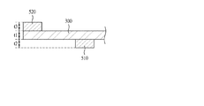
図1は、実施形態に係る照明ユニットを説明するための断面図である。 FIG. 1 is a cross-sectional view for explaining an illumination unit according to an embodiment.
図1に示すように、照明ユニットは、第1及び第2のリフレクタ210,220、光源モジュール100、光学部材300、カバー部材400、及び第1及び第2の突出部材510,520を備えている。
As shown in FIG. 1, the lighting unit includes first and
ここで、光源モジュール100は、第1のリフレクタ210と第2のリフレクタ220との間に配置されており、第2のリフレクタ220に隣接して配置されもよい。
Here, the
場合によって、光源モジュール100は、第2のリフレクタ220に接するとともに、第1のリフレクタ210から一定の間隔を置いて配置されてもよく、第1のリフレクタ210に接するとともに、第2のリフレクタ220から一定の間隔を置いて配置されてもよい。
In some cases, the
または、光源モジュール100は、第1のリフレクタ210及び第2のリフレクタ220の両方から一定の間隔を置いて配置されてもよく、第1のリフレクタ210及び第2のリフレクタ220の両方に接して配置されてもよい。
Alternatively, the
そして、光源モジュール100は、電極パターンを有する基板100bと、基板100b上に配置された少なくとも一つの光源100aと、を備えている。
The
ここで、光源モジュール100の光源100aは上面発光型(top view type)の発光ダイオードでよい。
Here, the
場合によって、光源100aは、側面発光型(side view type)の発光ダイオードであってもよい。
In some cases, the
そして、基板100bは、ポリエチレンテレフタレート(PET)、ガラス、ポリカーボネート(PC)、シリコン(Si)から選ばれるいずれか一物質からなるPCB(Printed Circuit Board)基板でもよく、フィルム形態のものでもよい。
The
また、基板100bとしては、単層PCB、多層PCB、セラミック基板、メタルコアPCBなどを選択的に使用している。
As the
ここで、基板100bは、反射コーティングフィルム及び反射コーティング物質層のいずれか一つが形成されていてもよく、光源100aで生成された光を第1のリフレクタ210の中央領域に反射させることができる。
Here, the
また、光源100aは、発光ダイオードチップ(LED chip)でもよく、発光ダイオードチップは、ブルーLEDチップまたは紫外線LEDチップで構成されてもよく、またはレッドLEDチップ、グリーンLEDチップ、ブルーLEDチップ、イエローグリーン(Yellow green)LEDチップ、ホワイトLEDチップの少なくとも一つまたは2以上を組み合わせたパッケージ形態で構成されてもよい。
The
そして、ホワイトLEDは、ブルーLED上にイエロー燐光(Yellow phosphor)を結合して具現してもよく、ブルーLED上にレッド燐光(Red phosphor)とグリーン燐光(Green phosphor)を同時に結合して具現してもよく、ブルーLED上にイエロー燐光(Yellow phosphor)、レッド燐光(Red phosphor)及びグリーン燐光(Green phosphor)を同時に結合して具現してもよい。 The white LED may be realized by combining yellow phosphor on a blue LED, and may be realized by simultaneously combining red phosphor and green phosphor on a blue LED. Alternatively, yellow phosphor, red phosphor, and green phosphor may be simultaneously combined on a blue LED.
また、第1のリフレクタ210と第2のリフレクタ220との間の空間にはエアーガイド(air guide)を有するように、第1のリフレクタ210と第2のリフレクタ220とが一定の間隔を置いて向かい合っている。
In addition, the
ここで、第1及び第2のリフレクタ210,220は、アルミニウム(Al)、銀(Ag)、金(Au)、二酸化チタン(TiO2)などのような高反射率を有する金属または金属酸化物を含んで構成されている。
Here, the first and
場合によって、第1及び第2のリフレクタ210,220は、高分子樹脂フレーム上に反射フィルムまたは反射シートを接着して形成してもよい。
In some cases, the first and
場合によっては、第1及び第2のリフレクタ210,220は、高分子樹脂フレーム上に金属または金属酸化物を蒸着またはコーティングして形成してもよく、金属インキを印刷して形成してもよい。
In some cases, the first and
ここで、第1及び第2のリフレクタ210,220は、互いに同じ物質で構成されていてもよいし、場合によっては、互いに異なる物質で構成されていてもよい。
Here, the 1st and
また、第1及び第2のリフレクタ210,220は、表面の一部に鋸歯状の反射パターンが形成されていてもよい。
The first and
ここで、反射パターンの表面は、扁平面または曲面になっている。 Here, the surface of the reflection pattern is a flat surface or a curved surface.
また、第1及び第2のリフレクタ210,220は、一部に傾斜面を有していてもよい。
Moreover, the 1st and
場合によって、第2のリフレクタ220は平坦な平面であり、第1のリフレクタ210は一部に傾斜面を有していてもよい。
In some cases, the
ここで、第1のリフレクタ210は、少なくとも一つの変曲点を有する少なくとも2つの傾斜面を有していてもよい。
Here, the
そして、第1のリフレクタ210の傾斜面は、第2のリフレクタ220の表面に対して一定の角度で傾斜した面になっており、傾斜面は、凹面(concave surface)、凸面(convex surface)、扁平面(flat surface)の少なくとも一つであればよい。
The inclined surface of the
場合によって、第1のリフレクタ210は、少なくとも一つの傾斜面と少なくとも一つの平面(flat surface)を有していてもよいが、第1のリフレクタ210の平面は、第2のリフレクタ220の平面と平行な面であればよい。
In some cases, the
ここで、第1のリフレクタ210の平面は、光源モジュール100の一部と重なっているとよい。
Here, the plane of the
また、第1のリフレクタ210は、少なくとも一つの変曲点を有する少なくとも2つの傾斜面を有し、変曲点を中心に隣接している第1及び第2の傾斜面の曲率は互いに異なっていてもよい。
The
一方、光学部材300は、第1のリフレクタ210から一定の空間を置いて配置されている。
On the other hand, the
そして、第1のリフレクタ210と光学部材300との間の空間にはエアーガイドが形成されている。
An air guide is formed in the space between the
ここで、光学部材300は、上面に凹凸パターンを有していてもよい。
Here, the
光学部材300は、光源モジュール100から出射した光を拡散させるためのもので、拡散効果を増大させるために上面に凹凸パターンが形成されていてもよい。
The
すなわち、光学部材300は、複数の層で形成されており、最上層またはいずれか一層の表面に凹凸パターンを有している。
That is, the
そして、凹凸パターンは、光源モジュール100に並んで配置されるストライプ状にすることができる。
The concave / convex pattern can be formed in a stripe shape arranged side by side in the
ここで、凹凸パターンは、光学部材300の表面に形成された突出部を有し、突出部は、相対する第1の面と第2の面とで構成され、第1の面と第2の面間の角は鈍角または鋭角であればよい。
Here, the concavo-convex pattern has a protrusion formed on the surface of the
場合によって、光学部材300は、少なくとも一つのシートで構成されてもよく、拡散シート、プリズムシート、輝度強化シートなどを選択的に含むことができる。
In some cases, the
ここで、拡散シートは、光源から発された光を拡散させ、プリズムシートは、拡散された光を発光領域にガイドし、輝度強化シートは輝度を強化させる。 Here, the diffusion sheet diffuses the light emitted from the light source, the prism sheet guides the diffused light to the light emitting region, and the brightness enhancement sheet enhances the brightness.
また、カバー部材400は、第2のリフレクタ220をカバーするように配置されており、光学部材300の両端部は、カバー部材400と第2のリフレクタ220との間に配置されている。
The
そして、第1の突出部材510は、光学部材300とカバー部材400との間に配置され、第2の突出部材520は、光学部材300と第2のリフレクタ220との間に配置されている。
The first projecting
ここで、カバー部材400から第1の突出部材510の一側面までの距離は、カバー部材400から第2の突出部材520の一側面までの距離よりも大きくなっている。
Here, the distance from the
また、第1の突出部材510は、光学部材300の中央領域に隣接して配置されており、第2の突出部材520は、光学部材300の端部に隣接して配置されている。
Further, the first projecting
これは、光学部材300の中央領域が下方に垂れる現象を防ぐためである。
This is to prevent a phenomenon in which the central region of the
例えば、第1の突出部材510は、光学部材300を支持する梃子のような役割を果たし、第2の突出部材520は、光学部材300の中央領域が下方に垂れないように光学部材300の端部を上方から下方に押す役割を果たすことによって、光学部材300の垂れを防止することができる。
For example, the first projecting
ここで、第1及び第2の突出部材510,520は、接着部材、緩衝部材、締結部材のいずれかであればよい。
Here, the 1st and
場合によって、第1の突出部材510は、カバー部材400から突出していてもよく、光学部材300から突出していてもよい。
In some cases, the first projecting
また、第2の突出部材520は、第2のリフレクタ220から突出していてもよく、光学部材300から突出していてもよい。
Further, the second projecting
実施形態として、光学部材300は、中央領域と、中央領域を包囲する周辺領域とを有しており、該光学部材300の周辺領域から第1及び第2の突出部材510,520が突出していてもよい。
As an embodiment, the
すなわち、第1及び第2の突出部材510,520は、光学部材300と同じ物質からなり、光学部材300の周辺領域から突出している
That is, the first and second projecting
ここで、光学部材300は、周辺領域に第1及び第2の突出部材510,520を含んでいるから、光学部材300の周辺領域の重量(weight)は、光学部材300の中央領域の重量よりも大きくなっている。
Here, since the
例えば、光学部材300の周辺領域の重量は、光学部材300の中央領域の重量よりも約0.1〜10倍大きくなっていてもよい。
For example, the weight of the peripheral region of the
このように、光学部材300は、カバー部材400に面する周辺領域に配置された第1の突出部材510と、第2のリフレクタ220に面する周辺領域に配置された第2の突出部材520とを有しているため、光学部材300の中央領域の垂れが防止される。
As described above, the
また、第1の突出部材510は、光学部材30の中央領域に隣接して配置されており、第2の突出部材520は光学部材300の端部に隣接して配置されている。
The first protruding
そのため、第1の突出部材510及び第2の突出部材520は互いにずれて配置されている。
Therefore, the first projecting
図2は、第1及び第2の突出部材の配置を示す断面図である。 FIG. 2 is a cross-sectional view showing the arrangement of the first and second protruding members.
図2に示すように、光学部材300は、中央領域と、中央領域を包囲する周辺領域を有している。
As shown in FIG. 2, the
ここで、第1及び第2の突出部材510,520の両方が光学部材300の周辺領域に配置されており、第1の突出部材510は光学部材300の中央領域に隣接して配置され、第2の突出部材520は光学部材300の端部301に隣接して配置されている。
Here, both the first and second projecting
ここで、第1及び第2の突出部材510,520は、接着部材、緩衝部材、締結部材のいずれか一つであればよい。
Here, the first and second projecting
場合によって、第1及び第2の突出部材510,520は、光学部材300から突出していてもよい。
In some cases, the first and second projecting
すなわち、第1及び第2の突出部材510,520は、光学部材300と同じ物質からなり、光学部材300の周辺領域から突出している。
That is, the first and second projecting
このように、光学部材300は、周辺領域に第1及び第2の突出部材510,520を含んでいるから、光学部材300の周辺領域の重量は、光学部材300の中央領域の重量よりも大きくなっている。
As described above, since the
例えば、光学部材300の周辺領域の重量は、光学部材300の中央領域の重量よりも約0.1〜10倍大きくなっていてもよい。
For example, the weight of the peripheral region of the
図3A乃至図3Cは、第1の突出部材と第2の突出部材との配置関係を示す断面図である。 3A to 3C are cross-sectional views showing the positional relationship between the first projecting member and the second projecting member.
図3A乃至図3Cに示すように、第1の突出部材510及び第2の突出部材520は互いにずれて配置されている。
As shown in FIGS. 3A to 3C, the first projecting
ここで、第1の突出部材510は、光学部材300の下部面に配置され、第2の突出部材520は、光学部材300の上部面に配置されている。
Here, the first projecting
この場合、図3Aに示すように、第1の突出部材510の一側面511と第2の突出部材520の一側面521は、間隔d1だけ離れて配置されている。
In this case, as shown in FIG. 3A, the one
場合によって、図3Bに示すように、第1の突出部材510の一側面511と第2の突出部材520の一側面521は、同一基準線上に配置されていてもよい。
In some cases, as shown in FIG. 3B, one
場合によっては、図3Cに示すように、第1の突出部材510と第2の突出部材520とが重なっていてもよい。すなわち、第1の突出部材510の一側面511は第2の突出部材520と、且つ第2の突出部材520の一側面521は第1の突出部材510と重なっていてもよい。
In some cases, as shown in FIG. 3C, the first projecting
このように、第1の突出部材510と第2の突出部材520は、一部領域が重なって配置されてもよいし、互いに重なることなく、一定の間隔を置いて配置されてもよい。
As described above, the first projecting
図4A乃至図4Cは、第1及び第2の突出部材間の間隔を示す断面図である。 4A to 4C are cross-sectional views illustrating the distance between the first and second protruding members.
図4Aに示すように、第1の突出部材510は光学部材300の下部面に配置され、第2の突出部材520は光学部材300の上部面に配置され、第1の突出部材510及び第2の突出部材520は互いにずれて配置されている。
As shown in FIG. 4A, the first projecting
ここで、第1の突出部材510の一側面511と第2の突出部材520の一側面521とが間隔d1だけ離れて配置されている。
Here, the one
この場合、第1の突出部材510の一側面511と第2の突出部材520の一側面521間の間隔d1は、光学部材300の厚さt1よりも大きくなっている。
In this case, a distance d1 between the one
場合によって、図4Bに示すように、第1の突出部材510の一側面511と第2の突出部材520の一側面521間の間隔d1は、光学部材300の厚さt1よりも小さくなっていてもよい。
In some cases, as shown in FIG. 4B, a distance d1 between the one
場合によっては、図4Cに示すように、第1の突出部材510の一側面511と第2の突出部材520の一側面521間の間隔d1は、光学部材300の厚さt1と同一の大きさになっていてもよい。
In some cases, as shown in FIG. 4C, a distance d1 between one
このように、第1及び第2の突出部材510,520間の間隔が異なっている理由は、光学部材300の面積によって下方に垂れる度合が異なるからである。
As described above, the reason why the distance between the first and second projecting
例えば、光学部材300の垂れの度合が大きいと、第1及び第2の突出部材間の間隔d1を大きくし、光学部材300の垂れの度合が小さいと、第1及び第2の突出部材間の間隔d1を小さくすればよい。
For example, when the degree of sagging of the
図5A乃至図5Dは、第2の突出部材の配置を示す断面図である。 5A to 5D are cross-sectional views illustrating the arrangement of the second projecting members.
図5A乃至図5Dに示すように、第2の突出部材520は、光学部材300の上部面に配置されるとともに、光学部材300の端部301に隣接して配置されている。
As shown in FIGS. 5A to 5D, the second projecting
ここで、第2の突出部材520の一側面521は光学部材300の中央領域に向くように配置されており、第2の突出部材520の他側面522は光学部材300の端部301に向くように配置されている。
Here, one
この場合、図5Aに示すように、第2の突出部材520の他側面522は、光学部材300の端部301の側面と一致するように配置されている。
In this case, as shown in FIG. 5A, the
場合によって、図5Bに示すように、第2の突出部材520の他側面522は、光学部材300の端部301の側面から間隔d2だけ離れて配置されてもよい。
In some cases, as illustrated in FIG. 5B, the
ここで、第2の突出部材520の他側面522と光学部材300の端部301の側面間の間隔d2は、光学部材300の厚さt1と同一になっている。
Here, the distance d2 between the
場合によって、図5Cに示すように、第2の突出部材520の他側面522と光学部材300の端部301の側面間の間隔d2は、光学部材300の厚さt1よりも小さくなっていてもよい。
In some cases, as shown in FIG. 5C, the distance d2 between the
場合によって、図5Dに示すように、第2の突出部材520の他側面522と光学部材300の端部301の側面間の間隔d2は、光学部材300の厚さt1よりも大きくなっていてもよい。
In some cases, as shown in FIG. 5D, even if the distance d2 between the
このように第2の突出部材520の配置が異なっている理由は、光学部材300がその面積によって下方に垂れる度合が異なり、それに応じて、光学部材300の端部を押す力を制御しなければならないからである。
The reason why the arrangement of the second projecting
図6A乃至図6Cは、第1及び第2の突出部材の厚さを示す断面図である。 6A to 6C are cross-sectional views showing the thicknesses of the first and second protruding members.
図6A乃至図6Cに示すように、第1の突出部材510は、光学部材300の下部面に配置され、第2の突出部材520は光学部材300の上部面に配置され、第1の突出部材510及び第2の突出部材520は互いにずれて配置されている。
As shown in FIGS. 6A to 6C, the first projecting
ここで、図6Aに示すように、第1の突出部材510の厚さt2は第2の突出部材520の厚さt3と同一になっいてもよい。
Here, as shown in FIG. 6A, the thickness t2 of the first protruding
そして、第1及び第2の突出部材510,520の厚さt2,t3のそれぞれは、光学部材300の厚さt1と同一であってもよい。
The thicknesses t2 and t3 of the first and second projecting
また、図6Bに示すように、第1の突出部材510の厚さt2は第2の突出部材520の厚さt3よりも小さくてもよい。
Further, as shown in FIG. 6B, the thickness t2 of the first projecting
そして、第1の突出部材510の厚さt2は光学部材300の厚さt1と同一であり、第2の突出部材520の厚さt3は光学部材300の厚さt1よりも大きくてもよい。
The thickness t2 of the first protruding
また、図6Cに示すように、第1の突出部材510の厚さt2は、第2の突出部材520の厚さt3よりも小さくてもよい。
Further, as shown in FIG. 6C, the thickness t2 of the first projecting
そして、第1の突出部材510の厚さt2は光学部材300の厚さt1よりも大きく、第2の突出部材520の厚さt3も光学部材300の厚さt1より大きくてもよい。
The thickness t2 of the first projecting
このように、第1及び第2の突出部材510,520の厚さが異なっている理由は、光学部材300がその面積によって下方に垂れる度合が異なり、これに応じて、光学部材300の端部を押す力を制御しなければならないからである。
As described above, the thicknesses of the first and second projecting
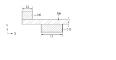
図7A乃至図7Cは、第1及び第2の突出部材の長さを示す断面図である。 7A to 7C are cross-sectional views showing the lengths of the first and second projecting members.
図7A乃至図7Cに示すように、第1の突出部材510は光学部材300の下部面に配置され、第2の突出部材520は光学部材300の上部面に配置され、第1の突出部材510及び第2の突出部材520は互いにずれて配置されている。
7A to 7C, the first protruding
ここで、図7Aに示すように、第1の突出部材510の長さL1は、第2の突出部材520の長さL2よりも小さくてもよい。
Here, as shown in FIG. 7A, the length L1 of the first protruding
この場合、第1の突出部材510の長さL1と第2の突出部材520の長さL2は、光学部材300の端部領域から中央領域へ向かうX方向の長さを指す。
In this case, the length L1 of the first protruding
また、図7Bに示すように、第1の突出部材510の長さL1と第2の突出部材520の長さL2は互いに同一であってもよい。
Further, as shown in FIG. 7B, the length L1 of the first projecting
場合によって、図7Cに示すように、第1の突出部材510の長さL1は第2の突出部材520の長さL2よりも小さくてもよい。
In some cases, as shown in FIG. 7C, the length L1 of the first protruding
このように、第1及び第2の突出部材510,520の長さが異なっている理由は、光学部材300がその面積によって下部に垂れる度合が異なり、それに応じて、光学部材300の端部を押す力を制御しなければならないからである。
As described above, the lengths of the first and second projecting
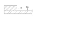
図8A及び図8Bは、第1の実施形態に係る第1の突出部材の材料を説明するための断面図である。 8A and 8B are cross-sectional views for explaining the material of the first projecting member according to the first embodiment.
図8Aに示すように、第1の突出部材510は、光学部材300の下部面から延突している一体型であってもよい。
As shown in FIG. 8A, the first projecting
すなわち、第1の突出部材510は、光学部材300と同じ物質であり、第1の突出部材510と光学部材300とが一体になっている。
That is, the first protruding
場合によって、図8Bに示すように、第1の突出部材510は、光学部材300の下部面に取り付け可能な分離型であってもよい。
In some cases, as shown in FIG. 8B, the first protruding
すなわち、第1の突出部材510は、光学部材300と異なる物質からなり、光学部材300から分離可能になっている。
That is, the first projecting
ここで、第1の突出部材510は、接着部材、緩衝部材、締結部材のいずれか一つであればよい。
Here, the first projecting
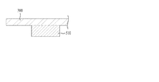
図9A及び図9Bは、第2の突出部材の材料を説明するための断面図である。 9A and 9B are cross-sectional views for explaining the material of the second projecting member.
図9Aに示すように、第2の突出部材520は、光学部材300の上部面から延突している一体型であってもよい。
As shown in FIG. 9A, the second projecting
すなわち、第2の突出部材520は、光学部材300と同じ物質であり、第2の突出部材520と光学部材300とが一体になっている。
That is, the second projecting
場合によって、図9Bに示すように、第2の突出部材520は、光学部材300の上部面に取り付け可能な分離型であってもよい。
In some cases, as shown in FIG. 9B, the second protruding
すなわち、第2の突出部材520は、光学部材300と異なる物質からなり、光学部材300から分離可能になっている。
That is, the second projecting
ここで、第2の突出部材520は、接着部材、緩衝部材、締結部材のいずれか一つであればよい。
Here, the second projecting
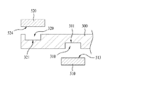
図10A及び図10Bは、第2の実施形態に係る第1の突出部材の材料を説明するための断面図である。 10A and 10B are cross-sectional views for explaining the material of the first projecting member according to the second embodiment.
図10Aに示すように、第1の突出部材510は、カバー部材400の下部面から延突した一体型であってもよい。
As shown in FIG. 10A, the first projecting
すなわち、第1の突出部材510はカバー部材400と同じ物質であり、第1の突出部材510とカバー部材400とが一体になっている。
That is, the first projecting
場合によって、図10Bに示すように、第1の突出部材510は、カバー部材400に取り付け可能な分離型であってもよい。
In some cases, as shown in FIG. 10B, the first protruding
すなわち、第1の突出部材510は、カバー部材400と異なる物質からなり、カバー部材400から分離可能になっている。
That is, the first projecting
ここで、第1の突出部材510は、接着部材、緩衝部材、締結部材のいずれか一つであればよい。
Here, the first projecting
図11は、第1及び第2の突出部材の材料を比較するための断面図である。 FIG. 11 is a cross-sectional view for comparing the materials of the first and second protruding members.
図11に示すように、第1の突出部材510は、光学部材300の下部面に配置され、第2の突出部材520は、光学部材300の上部面に配置され、第1の突出部材510及び第2の突出部材520は互いにずれて配置されている。
As shown in FIG. 11, the first projecting
ここで、第1の突出部材510は、カバー部材400に面する第1の面514と、光学部材300に面する第2の面513と、を有しており、第2の突出部材520は、光学部材300に面する第3の面524と、第2のリフレクタ220に面する第4の面523と、を有している。
Here, the first projecting
第1の突出部材510は、カバー部材400または光学部材300と同じ物質であってもよいし、カバー部材400または光学部材300と異なる物質であって、接着部材、緩衝部材、締結部材のいずれかであってもよい。
The first protruding
そして、第2の突出部材520は、第2のリフレクタ220または光学部材300と同じ物質であってもよいし、第2のリフレクタ220または光学部材300と異なる物質であって、接着部材、緩衝部材、締結部材のいずれか一つであってもよい。
The second projecting
また、第1及び第2の突出部材510,520は、互いに同じ物質であってもよく、場合によって、互いに異なる物質であってもよい。
Further, the first and second projecting
場合によっては、第1の突出部材510の第1の面514及び第2の面513と、第2の突出部材520の第3の面524及び第4の面523の少なくとも一つには接着部材、緩衝部材、締結部材のいずれか一つが配置されていてもよい。
In some cases, at least one of the
図12は、接着部材を有している第1及び第2の突出部材を示す断面図である。 FIG. 12 is a cross-sectional view showing first and second projecting members having adhesive members.
図12に示すように、第1の突出部材510は光学部材300の下部面に配置され、第2の突出部材520は光学部材300の上部面に配置されており、第1の突出部材510及び第2の突出部材520は互いにずれて配置されている。
As shown in FIG. 12, the first projecting
ここで、第1の突出部材510とカバー部材400との間、及び第1の突出部材510と光学部材300との間のうち、少なくとも一方に接着部材610が配置され、第2の突出部材520と光学部材300との間、及び第2の突出部材520と第2のリフレクタ220との間のうち、少なくとも一方に接着部材610が配置されていればよい。
Here, the
ここで、接着部材610は、液状のシリコンゴムまたは合成ゴムに熱伝導性パウダーを混合したペーストを熱硬化したものであり、接着信頼性に優れている。
Here, the
また、接着部材610は熱伝導性にも優れており、光源モジュールから伝達される熱を效果的に外部に放出することができる。
The
図13は、緩衝部材を有している第1及び第2の突出部材を示す断面図である。 FIG. 13 is a cross-sectional view showing first and second projecting members having a buffer member.
図13に示すように、第1の突出部材510は、光学部材300の下部面に配置され、第2の突出部材520は光学部材300の上部面に配置されており、第1の突出部材510及び第2の突出部材520は互いにずれて配置されている。
As shown in FIG. 13, the first projecting
ここで、第1の突出部材510とカバー部材400との間、及び第1の突出部材510と光学部材300との間のうち、少なくとも一方に緩衝部材620が配置されており、第2の突出部材520と光学部材300との間、及び第2の突出部材520と第2のリフレクタ220との間のうち、少なくとも一方に緩衝部材620が配置されていればよい。
Here, the
ここで、緩衝部材620は、熱伝導性パウダーが含まれたシリコンゴム、または熱伝導性パウダーが含まれた合成ゴムでよい。
Here, the
熱伝導性パウダーとしては、熱伝導性に優れた金属である銀(Ag)、銅(Cu)、金(Au)、アルミニウム(Al)などを含むことができる。 The thermally conductive powder may include silver (Ag), copper (Cu), gold (Au), aluminum (Al), etc., which are metals having excellent thermal conductivity.
すなわち、緩衝部材620は、液状のシリコンゴムまたは合成ゴムに熱伝導性パウダーを混合したのち熱硬化して作製することができる。
That is, the
このように緩衝部材620を配置すると、外部衝撃に弱い光学部材300が第1及び第2の突出部材510,520により損傷することを防止することができる。
When the
また、緩衝部材620は、熱伝導性に優れており、光源モジュールから伝達される熱を效果的に外部に放出することもできる。
Further, the
図14は、締結部材を有している第1及び第2の突出部材を示す断面図である。 FIG. 14 is a cross-sectional view showing first and second projecting members having a fastening member.
図14に示すように、第1の突出部材510は光学部材300の下部面に配置され、第2の突出部材520は光学部材300の上部面に配置され、第1の突出部材510及び第2の突出部材520は互いにずれて配置されている。
As shown in FIG. 14, the first projecting
ここで、第1の突出部材510とカバー部材400との間、及び第1の突出部材510と光学部材300との間のうち、少なくとも一方に締結部材630が配置され、第2の突出部材520と光学部材300との間、及び第2の突出部材520と第2のリフレクタ220との間のうち、少なくとも一方に締結部材630が配置されていてもよい。
Here, the
ここで、締結部材630はスクリューのような締結ねじでよく、締結部材630は、熱伝導性に優れた金属、例えば、銀(Ag)、銅(Cu)、金(Au)、アルミニウム(Al)などで構成すればよい。
Here, the
このように締結部材630を配置すると、第1及び第2の突出部材510,520を強固に固定して光学部材300の垂れを防止する他、光源モジュールから伝達される熱を效果的に外部に放出することもできる。
When the
図15A乃至図15Cは、溝を有する光学部材を示す断面図である。 15A to 15C are cross-sectional views showing an optical member having a groove.
図15Aに示すように、光学部材300は、第2の突出部材520に面する領域に、少なくとも一つの第2の溝320が配置されている。
As shown in FIG. 15A, in the
ここで、第2の溝320の面積は、第2の突出部材520の面積よりも大きくなっている。
Here, the area of the
場合によって、第2の溝320の面積は、第2の突出部材520の面積と同一になっていてもよい。
In some cases, the area of the
そして、第2の溝320の高さh1は、光学部材300の厚さt1よりも小さくなっており、第2の溝320の高さh1と光学部材300の厚さt1との比は、1:2〜10でよい。
The height h1 of the
第2の溝320の高さh1が小さすぎると、第2の突出部材520を固定し難く、第2の溝320の高さh1が大きすぎると、光学部材300が割れやすくなる。
If the height h1 of the
そして、図15Bに示すように、光学部材300は、第1の突出部材510に面する領域に、少なくとも一つの第1の溝310が配置されていてもよい。
Then, as shown in FIG. 15B, in the
ここで、第1の溝310の面積は、第1の突出部材510の面積よりも大きくなっている。
Here, the area of the
場合によって、第1の溝310の面積は、第1の突出部材510の面積と同一になっていてもよい。
In some cases, the area of the
そして、第1の溝310の高さh2は、光学部材300の厚さt1よりも小さくなっており、第1の溝310の高さh2と光学部材300の厚さt1との比は、1:2〜10でよい。
The height h2 of the
第1の溝310の高さh2が小さすぎると、第1の突出部材510が固定し難く、第1の溝310の高さh2が大きすぎると、光学部材300が割れやすくなる。
If the height h2 of the
また、図15Cに示すように、光学部材300は、第1の突出部材510に面する領域に少なくとも一つの第1の溝310が配置され、且つ第2の突出部材520に面する領域に少なくとも一つの第2の溝320が配置されていてもよい。
15C, the
ここで、第1の溝310の面積は、第1の突出部材510の面積よりも大きくなっており、第2の溝320の面積は、第2の突出部材520の面積よりも大きくなっている。
Here, the area of the
場合によって、第1の溝310の面積は、第1の突出部材510の面積と同一であってもよく、第2の溝320の面積は、第2の突出部材520の面積と同一であってもよい。
In some cases, the area of the
図16は、光学部材の溝の大きさを示す断面図である。 FIG. 16 is a cross-sectional view showing the size of the groove of the optical member.
図16に示すように、光学部材300は、第1の突出部材510に面する領域に少なくとも一つの第1の溝310が配置されており、第2の突出部材520に面する領域に少なくとも一つの第2の溝320が配置されている。
As shown in FIG. 16, in the
ここで、第1の溝310の底面311の面積は、第1の突出部材510の第2の面513の面積よりも小さくなっている。
Here, the area of the
そして、第2の溝320の底面321の面積は、第2の突出部材520の第3の面524の面積よりも小さくなっている。
The area of the
そのため、第1の溝310の底面311と第1の突出部材510の第2の面513との間にはエアーギャップが形成されており、第2の溝320の底面321と第2の突出部材520の第3の面524との間にもエアーギャップが形成されている。
Therefore, an air gap is formed between the
場合によって、第1の溝310の底面311と第1の突出部材510の第2の面513との間、及び第2の溝320の底面321と第2の突出部材520の第3の面524との間には、接着部材、緩衝部材、締結部材のいずれか一つが配置されてもよい。
In some cases, between the
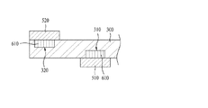
図17A乃至図17Cは、光学部材の溝に配置されている第1及び第2の突出部材を示す断面図である。 17A to 17C are cross-sectional views showing the first and second projecting members arranged in the groove of the optical member.
図17Aに示すように、光学部材300は、第1の突出部材510に面する領域に少なくとも一つの第1の溝310が配置されており、第2の突出部材520に面する領域に少なくとも一つの第2の溝320が配置されている。
As shown in FIG. 17A, in the
ここで、第1の溝310の面積は第1の突出部材510の面積よりも小さくなっており、第2の溝320の面積は第2の突出部材520の面積よりも小さくなっている。
Here, the area of the
そして、第1の溝310と第2の溝320内には接着部材610が配置されていてもよい。
An
ここで、接着部材610は、液状のシリコンゴムまたは合成ゴムに熱伝導性パウダーを混合したペーストを熱硬化したものであり、接着信頼性に優れている。
Here, the
また、図17Bに示すように、第1の溝310と第2の溝320内に緩衝部材620が配置されていてもよい。
Further, as shown in FIG. 17B, a
ここで、緩衝部材620は、熱伝導性パウダーが含まれたシリコンゴム、または熱伝導性パウダーが含まれた合成ゴムでよい。
Here, the
熱伝導性パウダーとしては、熱伝導性に優れた金属である銀(Ag)、銅(Cu)、金(Au)、アルミニウム(Al)などを含むことができる。 The thermally conductive powder may include silver (Ag), copper (Cu), gold (Au), aluminum (Al), etc., which are metals having excellent thermal conductivity.
すなわち、緩衝部材620は、液状のシリコンゴムまたは合成ゴムに熱伝導性パウダーを混合したのち熱硬化して作製すればよい。
In other words, the
また、図17Cに示すように、第1の溝310と第2の溝320内に締結部材630が配置されていてもよい。
In addition, as illustrated in FIG. 17C, the
ここで、締結部材630は、スクリューのような締結ねじであってもよく、締結部材630は、熱伝導性に優れた金属、例えば、銀(Ag)、銅(Cu)、金(Au)、アルミニウム(Al)などで構成すればよい。
Here, the
図18は、図1における第1及び第2のリフレクタを示す断面図である。 18 is a cross-sectional view showing the first and second reflectors in FIG.
図18に示すように、第1及び第2のリフレクタ210,220は互いに異なる高さに配置されており、光源モジュール100は、第1のリフレクタ210と第2のリフレクタ220との間に配置されている。
As shown in FIG. 18, the first and
ここで、第2のリフレクタ220は平坦な平面であり、第1のリフレクタ210は一部に傾斜面を有している。
Here, the
この場合、第1のリフレクタ210の傾斜面は、第2のリフレクタ220の平面に対して傾斜しており、少なくとも一つの変曲点を有する少なくとも2つの傾斜面を有してもよい。
In this case, the inclined surface of the
例えば、第1のリフレクタ210は、変曲点Pを中心に隣接している第1の領域と第2の領域を有しており、第1の領域は第1の傾斜面に対応し、第2の領域は第2の傾斜面に対応する。
For example, the
ここで、第1の傾斜面は第1の曲率半径R1を有する曲面であり、第2の傾斜面は第2の曲率半径R2を有する曲面でよい。 Here, the first inclined surface may be a curved surface having a first radius of curvature R1, and the second inclined surface may be a curved surface having a second radius of curvature R2.
この場合、第1の傾斜面の第1の曲率半径R1と第2の傾斜面の第2の曲率半径R2は互いに異なっていてもよい。 In this case, the first curvature radius R1 of the first inclined surface and the second curvature radius R2 of the second inclined surface may be different from each other.
例えば、第1のリフレクタ210の第1の傾斜面は光源モジュール100に隣接しており、第1の傾斜面の第1の曲率半径R1は、第2の傾斜面の第2の曲率半径R2よりも小さくなっていてもよい。
For example, the first inclined surface of the
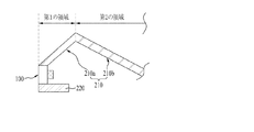
図19A乃至図19Dは、第1のリフレクタの傾斜面を示す図である。 19A to 19D are views showing the inclined surface of the first reflector.
図19Aに示すように、第1のリフレクタ210は、第1の領域210a及び第2の領域210bを有しており、第1の領域210aは、光源モジュール100及び第2のリフレクタ220の一部と重なり合っており、第2のリフレクタ220の表面に対して傾斜している傾斜面になっている。
As shown in FIG. 19A, the
ここで、第1の領域210aの傾斜面は、光源モジュール100から上方に傾斜した扁平面になっている。
Here, the inclined surface of the
そして、第2の領域210bは、第2のリフレクタ220の表面に対して傾斜した傾斜面になっており、第2の領域210bの傾斜面は、第1の領域210aの傾斜面から下方に傾斜した扁平面になっている。
The
ここで、第1の領域210aの傾斜面の勾配と第2の領域210bの傾斜面の勾配は互いに異なっていてもよい。
Here, the gradient of the inclined surface of the
例えば、第1の領域210aの傾斜面の勾配が第2の領域210bの傾斜面の勾配よりも大きくなっていてもよい。
For example, the gradient of the inclined surface of the
また、第1の領域210aの面積S1は、第2の領域210bの面積S2よりも大きくなっていてもよく、第1の領域210aの面積S1と第2の領域210bの面積S2との比は1.1〜20:1でよい。
The area S1 of the
また、図19Bに示すように、第1のリフレクタ210は、第1の領域210a及び第2の領域210bを有しており、第1の領域210aは、光源モジュール100及び第2のリフレクタ220の一部と重なり合っており、第2のリフレクタ220の表面に対して傾斜した傾斜面になっている。
Further, as shown in FIG. 19B, the
ここで、第1の領域210aの傾斜面は、光源モジュール100から上方に傾斜した凹んだ曲面になっている。
Here, the inclined surface of the
そして、第2の領域210bは、第2のリフレクタ220の表面から傾斜した傾斜面になっており、第2の領域210bの傾斜面は、第1の領域210aの傾斜面から下方に傾斜した凹んだ曲面になっている。
The
ここで、第1の領域210aの傾斜面の曲率半径と、第2の領域210bの傾斜面の曲率半径とは、互いに異なっていてもよい。
Here, the radius of curvature of the inclined surface of the
例えば、第1の領域210aの傾斜面の曲率半径は、第2の領域210bの傾斜面の曲率半径よりも小さくなっていてもよい。
For example, the radius of curvature of the inclined surface of the
また、第1の領域210aの面積S1は、第2の領域210bの面積S2よりも大きくなっていてもよく、第1の領域210aの面積S1と第2の領域210bの面積S2との比は、1.1〜20:1でよい。
The area S1 of the
そして、図19Cに示すように、第1のリフレクタ210は、第1の領域210a及び第2の領域210bを有しており、第1の領域210aは、光源モジュール100及び第2のリフレクタ220の一部と重なり合っており、第2のリフレクタ220の表面に対し傾斜した傾斜面になっている。
19C, the
ここで、第1の領域210aの傾斜面は、光源モジュール100から上方に傾斜した扁平面になっている。
Here, the inclined surface of the
そして、第2の領域210bは、第2のリフレクタ220の表面に対して傾斜した傾斜面になっており、第2の領域210bの傾斜面は、第1の領域210aの傾斜面から下方に傾斜した凹んだ曲面になっている。
The
ここで、第1の領域210aの面積S1は、第2の領域210bの面積S2よりも大きくなっていてもよく、第1の領域210aの面積S1と第2の領域210bの面積S2との比は、1.1〜20:1でよい。
Here, the area S1 of the
また、図19Dに示すように、第1のリフレクタ210は、第1の領域210a及び第2の領域210bを有しており、第1の領域210aは、光源モジュール100及び第2のリフレクタ22の0一部に重なり合っており、第2のリフレクタ220の表面に対して傾斜した傾斜面になっている。
Further, as shown in FIG. 19D, the
ここで、第1の領域210aの傾斜面は、光源モジュール100から上方に傾斜した凹んだ曲面になっている。
Here, the inclined surface of the
そして、第2の領域210bは、第2のリフレクタ220の表面に対して傾斜した傾斜面になっており、第2の領域210bの傾斜面は、第1の領域210aの傾斜面から下方に傾斜した扁平面になっている。
The
ここで、第1の領域210aの面積S1は、第2の領域210bの面積S2よりも大きくなっていてもよく、第1の領域210aの面積S1と第2の領域210bの面積S2との比は、1.1〜20:1でよい。
Here, the area S1 of the
図20A乃至図20Dは、傾斜面を有する第2のリフレクタを示す図である。図20Aは、傾斜面が扁平面である場合を示し、図20B、図20C及び図20Dは、傾斜面が曲面である場合を示している。 20A to 20D are diagrams illustrating a second reflector having an inclined surface. 20A shows a case where the inclined surface is a flat surface, and FIGS. 20B, 20C and 20D show a case where the inclined surface is a curved surface.
図20A乃至図20Dに示すように、光源モジュール100に面する第2のリフレクタ220の一側表面は、第2のリフレクタ220の他側表面に対して一定の角度で傾斜した傾斜面になっていてもよい。
As shown in FIGS. 20A to 20D, one side surface of the
ここで、傾斜面の傾斜角度θは、第2のリフレクタ220の他側表面に平行な水平面に対して1〜85°になっている。
Here, the inclination angle θ of the inclined surface is 1 to 85 ° with respect to a horizontal plane parallel to the other surface of the
そのため、第2のリフレクタ220の厚さは、光源モジュール100から遠ざかるにつれて漸次減少することもあり、漸次増加することもある。
Therefore, the thickness of the
すなわち、第2のリフレクタ220は、光源モジュール100に隣接した領域の厚さt11と、光源モジュール100から遠い領域の厚さt12とが互いに異なっていてもよい。例えば、図20A及び図20Bに示すように、光源モジュール100に隣接した領域の厚さt11が、光源モジュール100から遠い領域の厚さt12よりも大きくなっていてもよい。
That is, in the
場合によって、図20C及び図20Dに示すように、光源モジュール100に隣接した領域の厚さt11が、光源モジュール100から遠い領域の厚さt12よりも小さくなっていてもよい。
In some cases, as shown in FIGS. 20C and 20D, the thickness t11 of the region adjacent to the
また、図20Dに示すように、第2のリフレクタ220は、傾斜面、平面の両方を有していてもよい。
Moreover, as shown to FIG. 20D, the
すなわち、第2のリフレクタ220において、光源モジュール100に隣接した領域は傾斜面になっており、光源モジュール100から遠い領域は平面になっていてもよい。
That is, in the
ここで、傾斜面の長さL11は、平面の長さL12と同一になっていてもよく、場合によって、互いに異なっていてもよい。 Here, the length L11 of the inclined surface may be the same as the length L12 of the plane, or may be different from each other in some cases.
そして、第2のリフレクタ220の一側表面には、所定の反射パターンが形成されていてもよい。
A predetermined reflection pattern may be formed on one surface of the
図21A乃至図21Dは、反射パターンを有している第2のリフレクタを示す図である。 FIG. 21A to FIG. 21D are diagrams illustrating a second reflector having a reflection pattern.
図21Aは、反射パターン225が鋸歯状になっており、且つ反射パターン225の表面は扁平面である場合を示し、図21B及び図21Cは、反射パターン225は鋸歯状になっており、且つ反射パターン225の表面は曲面である場合を示す。
21A shows a case where the
ここで、図21Bは、反射パターン225の表面が凹んだ曲面になっており、図21Cは、反射パターン225の表面が膨らんだ曲面になっている。
Here, FIG. 21B is a curved surface in which the surface of the
場合によって、図21Dに示すように、反射パターン225の大きさが、第2のリフレクタ220の端部からオープン領域へ行くほど漸次増加していてもよい。
In some cases, as shown in FIG. 21D, the size of the
このように第2のリフレクタ220上に反射パターン225を形成すると、光反射の効果に加えて、光を均一に拡散する拡散効果も得ることができる。
When the
そのため、このような反射パターン225は、ライトユニットの全体輝度分布に応じて、該当の領域に様々な大きさで形成すればよい。
Therefore, such a
図22A乃至図22Dは、光源モジュールと第1及び第2のリフレクタとの配置関係を説明するための図である。 22A to 22D are views for explaining the arrangement relationship between the light source module and the first and second reflectors.
図22Aに示すように、光源モジュール100は、第1のリフレクタ210と第2のリフレクタ220の両方に接していてもよい。
As shown in FIG. 22A, the
このように光源モジュール100を配置すると、照明ユニットの輝度を均一にさせる他、全体的な照明ユニットの厚さを減らすことができる。
When the
また、図22Bに示すように、光源モジュール100は、第2のリフレクタ220から第1の距離d21だけ離れており、第1のリフレクタ210から第2の距離d22だけ離れていてもよい。
22B, the
ここで、第1の距離d21と第2の距離d22は、互いに同一であってもよく、互いに異なっていてもよい。 Here, the first distance d21 and the second distance d22 may be the same or different from each other.
一例として、第1の距離d21は、第2の距離d22よりも小さくてもよい。 As an example, the first distance d21 may be smaller than the second distance d22.
また、図22Cに示すように、光源モジュール100は、第2のリフレクタ220に接しており、第1のリフレクタ210から第2の距離d22だけ離れていてもよい。
22C, the
ここで、光源モジュール100は、第2のリフレクタ220に接することによって、ホットスポットを防止し、且つ光源モジュール100から遠い領域に光を伝達することができる。
Here, the
そして、図22Dに示すように、光源モジュール100は、第2のリフレクタ220から第2の距離d22だけ離れており、第2のリフレクタ210に接していてもよい。
22D, the
図23は、図1の光学部材を示す断面図である。 23 is a cross-sectional view showing the optical member of FIG.
図23に示すように、光学部材300は、上部表面に凹凸パターン310を有している。
As shown in FIG. 23, the
光学部材300は、光源モジュールから発された光を拡散させるためのもので、拡散効果を増大させるために上部表面に凹凸パターン310を有していてもよい。
The
すなわち、光学部材300は、複数の層で形成されており、最上層またはいずれか一層の表面に凹凸パターン310を有することができる。
That is, the
そして、凹凸パターン310は、光源モジュールに並んで配置されるストライプ状になっているとよい。
And the uneven |
ここで、凹凸パターン310は、光学部材300表面に形成された突出部を有し、突出部は、相対する第1の面と第2の面で構成され、第1の面と第2の面間の角は、鈍角または鋭角でよい。
Here, the concavo-
場合によって、光学部材300は、少なくとも一つのシートからなり、拡散シート、プリズムシート、輝度強化シートなどを選択的に含むことができる。
In some cases, the
ここで、拡散シートは、光源から発された光を拡散させ、プリズムシートは、拡散された光を発光領域にガイドし、輝度強化シートは輝度を強化させる。 Here, the diffusion sheet diffuses the light emitted from the light source, the prism sheet guides the diffused light to the light emitting region, and the brightness enhancement sheet enhances the brightness.
このように、実施形態は、光学部材の端部に突出部材を配置することで、光学部材の垂れを改善することができる。 As described above, in the embodiment, the sagging of the optical member can be improved by arranging the protruding member at the end of the optical member.
また、実施形態は、導光板を用いずに、一部に傾斜面を有するエアーガイド用のリフレクタを用いているため、軽量で、作製コストが低く、且つ均一な輝度を提供することができる。 In addition, since the embodiment uses an air guide reflector having an inclined surface in part without using a light guide plate, the embodiment is lightweight, can be manufactured at low cost, and can provide uniform luminance.
その結果、照明ユニットの経済性及び信頼性が向上する他、広い室内空間に適したものとすることができる。 As a result, the economy and reliability of the lighting unit can be improved and the lighting unit can be suitable for a wide indoor space.
また、以上の実施形態に記載された第1及び第2の突出部材を備えるバックライトユニット、表示装置、指示装置、照明システムを具現することもでき、例えば、照明システムとしてはランプ、街灯を含むことができる。 In addition, a backlight unit including the first and second projecting members described in the above embodiments, a display device, a pointing device, and a lighting system can be implemented. For example, the lighting system includes a lamp and a streetlight. be able to.
図24は、実施形態に係る照明ユニットを有するディスプレイモジュールを示す図である。 FIG. 24 is a diagram illustrating a display module having the illumination unit according to the embodiment.
図24に示すように、ディスプレイモジュール20は、ディスプレイパネル800及びライトユニット700を備えている。
As shown in FIG. 24, the
ディスプレイパネル800は、均一なセルギャップが維持されるように互いに相対して貼り合わせられたカラーフィルタ基板810とTFT(Thin Film Transistor)基板820とを有し、両基板810,820の間に液晶層(図示せず)が挟持されている。
The
なお、ディスプレイパネル800の上側及び下側にはそれぞれ、上部偏光板830及び下部偏光板840が配置されており、具体的には、カラーフィルタ基板810の上面に上部偏光板830が配置され、TFT基板820の下面に下部偏光板840が配置されている。
An upper
図示してはいないが、ディスプレイパネル800の側面には、パネル800を駆動させるための駆動信号を生成するゲート及びデータ駆動部が備えられていてもよい。
Although not shown, the side surface of the
図25及び図26は、実施形態に係るディスプレイ装置を示す図である。 25 and 26 are diagrams showing the display device according to the embodiment.
図25を参照すると、ディスプレイ装置1は、ディスプレイモジュール20と、ディスプレイモジュール20を取り囲むフロントカバー30及びバックカバー35と、バックカバー35に設けられた駆動部55と、駆動部55を覆う駆動部カバー40と、で構成されている。
Referring to FIG. 25, the
フロントカバー30は、光を透過させる透明な材質の前面パネル(図示せず)を有することができ、前面パネルは、一定の間隔を置いてディスプレイモジュール20を保護し、ディスプレイモジュール20から放出する光を透過させて、ディスプレイモジュール20で表示される映像が外部から見られるようにする。
The
バックカバー35は、フロントカバー30と結合してディスプレイモジュール20を保護することができる。
The
バックカバー35の一面には駆動部55が配置されている。
A
駆動部55は、駆動制御部55a、メインボード55b、及び電源ボード55cを有している。
The
駆動制御部55aは、タイミングコントローラでよく、ディスプレイモジュール20の各ドライバーICの動作タイミングを調節する駆動部であり、メインボード55bは、タイミングコントローラにVシンク、Hシンク及びR,G,B解像度信号を伝達する駆動部であり、電源ボード55cは、ディスプレイモジュール20に電源を印加する駆動部である。
The
駆動部55は、バックカバー35に配設されて、駆動部カバー40に覆われている。
The
バックカバー35には複数の孔が設けられて、ディスプレイモジュール20と駆動部55とが接続するようにし、ディスプレイ装置1を支持するスタンド60が備えられている。
The
一方、図26に示すように、駆動部55の駆動制御部55aはバックカバー35に設けられており、メインボード55bと電源ボード55cはスタンド60に設けられていてもよい。
On the other hand, as shown in FIG. 26, the
この場合、駆動部カバー40は、バックカバー35に設けられた駆動部55のみを覆っている。
In this case, the
本実施形態では、メインボード55bと電源ボード55cを別体として構成したが、一体の統合ボードにしてもよく、それに限定されない。
In the present embodiment, the
他の実施形態は、以上の実施形態に記載された第1及び第2の突出部材を備えているバックライトユニット、表示装置、指示装置、照明システムにすることができ、例えば、照明システムとしてはランプ、街灯を含むことができる。 Other embodiments can be a backlight unit, a display device, a pointing device, and a lighting system including the first and second projecting members described in the above embodiments. For example, as a lighting system, Lamps, street lights can be included.
以上では種々の実施形態を挙げて本発明を説明してきたが、本発明の精神及び範囲を逸脱しない限度内で、種々の他の変形及び態様が可能であるということは、当該技術の分野における通常の知識を有する当業者にとっては明らかである。特に、本発明の詳細な説明、図面及び添付の請求項の範囲内で構成要素及び/またはその組み合わせの様々な変形及び修正が可能である。これら構成要素及び/またはその組み合わせの様々な変形及び修正に加えて、その他の利用が当業者には明らかである。 Although the present invention has been described with reference to various embodiments, it is understood that various other modifications and modes are possible within the technical field without departing from the spirit and scope of the present invention. It will be apparent to those skilled in the art having ordinary knowledge. In particular, various variations and modifications of the components and / or combinations thereof are possible within the scope of the detailed description of the invention, the drawings, and the appended claims. In addition to various variations and modifications of these components and / or combinations thereof, other uses will be apparent to those skilled in the art.
Claims (19)
前記第1のリフレクタの両側に配置された第2のリフレクタと、
前記第1のリフレクタと第2のリフレクタとの間に配置された少なくとも一つの光源モジュールと、
前記第2のリフレクタをカバーするカバー部材と、
前記カバー部材と前記第2のリフレクタとの間に配置され、前記第1のリフレクタと向かい合っている光学部材と、
前記光学部材と前記カバー部材との間に配置された第1の突出部材と、
前記光学部材と前記第2のリフレクタとの間に配置された第2の突出部材と、
を備え、
第1のリフレクタは、第1の領域及び第2の領域を有し、
前記第1の領域は、前記光源モジュール及び前記第2のリフレクタの一部に垂直方向に重なり、前記光源モジュールから上方に向かって傾斜した平面であり、前記第2の領域は、前記第1の領域から下方に向かって傾斜した凹んだ曲面であり、
前記第2のリフレクタは、前記光源モジュールに隣接した傾斜面、及び前記光源モジュールから離れた平面を有し、
前記第2のリフレクタの表面には反射パターンが設けられている、
照明ユニット。 A first reflector;
A second reflector disposed on both sides of the first reflector;
At least one light source module disposed between the first reflector and the second reflector;
A cover member covering the second reflector;
An optical member disposed between the cover member and the second reflector and facing the first reflector;
A first projecting member disposed between the optical member and the cover member;
A second projecting member disposed between the optical member and the second reflector;
With
The first reflector has a first region and a second region;
The first region is a plane that vertically overlaps a part of the light source module and the second reflector and is inclined upward from the light source module, and the second region is the first region. A concave curved surface inclined downward from the region,
The second reflector has an inclined surface adjacent to the light source module, and a plane away from the light source module,
A reflection pattern is provided on the surface of the second reflector,
Lighting unit.
Applications Claiming Priority (2)
| Application Number | Priority Date | Filing Date | Title |
|---|---|---|---|
| KR10-2012-0018485 | 2012-02-23 | ||
| KR1020120018485A KR101943447B1 (en) | 2012-02-23 | 2012-02-23 | illumination unit and display apparatus for using the same |
Publications (3)
| Publication Number | Publication Date |
|---|---|
| JP2013175461A JP2013175461A (en) | 2013-09-05 |
| JP2013175461A5 JP2013175461A5 (en) | 2016-03-31 |
| JP6193585B2 true JP6193585B2 (en) | 2017-09-06 |
Family
ID=47749659
Family Applications (1)
| Application Number | Title | Priority Date | Filing Date |
|---|---|---|---|
| JP2013033475A Active JP6193585B2 (en) | 2012-02-23 | 2013-02-22 | Illumination unit and display device using the same |
Country Status (6)
| Country | Link |
|---|---|
| US (1) | US8944624B2 (en) |
| EP (1) | EP2631536B1 (en) |
| JP (1) | JP6193585B2 (en) |
| KR (1) | KR101943447B1 (en) |
| CN (1) | CN103292214B (en) |
| TW (1) | TWI593917B (en) |
Families Citing this family (10)
| Publication number | Priority date | Publication date | Assignee | Title |
|---|---|---|---|---|
| KR101902394B1 (en) * | 2011-12-12 | 2018-09-28 | 엘지이노텍 주식회사 | illumination unit and display apparatus for using the same |
| TWI563219B (en) | 2013-10-28 | 2016-12-21 | Epistar Corp | Illumination system having semiconductor light source module |
| CN104100886B (en) * | 2014-06-30 | 2016-08-03 | 北京京东方视讯科技有限公司 | A kind of backlight, display device and method for controlling backlight thereof thereof |
| JP6216301B2 (en) * | 2014-09-19 | 2017-10-18 | ミネベアミツミ株式会社 | Lighting device |
| JP6390396B2 (en) * | 2014-12-10 | 2018-09-19 | レシップホールディングス株式会社 | LED lights |
| US10317021B2 (en) | 2017-02-24 | 2019-06-11 | Whiteoptics Llc | Linear light emitting diode luminaires |
| KR20190086300A (en) | 2018-01-12 | 2019-07-22 | 엘지이노텍 주식회사 | Lighting module and lighting apparatus |
| US11002425B1 (en) | 2019-03-08 | 2021-05-11 | Abl Ip Holding Llc | Optical cover with faceted surface |
| US11346526B1 (en) | 2019-03-08 | 2022-05-31 | Abl Ip Holding Llc | Area optical cover with faceted surface |
| CN212390198U (en) * | 2020-06-22 | 2021-01-22 | 漳州立达信光电子科技有限公司 | Panel light |
Family Cites Families (21)
| Publication number | Priority date | Publication date | Assignee | Title |
|---|---|---|---|---|
| DE3929955A1 (en) * | 1989-09-08 | 1991-03-14 | Inotec Gmbh Ges Fuer Innovativ | LIGHT SPOTLIGHTS |
| JP3605472B2 (en) * | 1996-05-31 | 2004-12-22 | 大日本印刷株式会社 | Extension support jig for films and sheets |
| JP3173453B2 (en) * | 1998-03-13 | 2001-06-04 | スタンレー電気株式会社 | Signal lights for vehicles |
| JP2960928B1 (en) * | 1998-07-24 | 1999-10-12 | スタンレー電気株式会社 | Signal lights for vehicles |
| JP4705470B2 (en) * | 2003-06-16 | 2011-06-22 | 三菱電機株式会社 | Planar light source device and display device using the same |
| JP4746301B2 (en) * | 2004-10-01 | 2011-08-10 | ライツ・アドバンスト・テクノロジー株式会社 | Backlight unit |
| TWI258044B (en) * | 2005-06-01 | 2006-07-11 | Au Optronics Corp | Direct-type backlight unit structure |
| US7267451B2 (en) * | 2005-07-13 | 2007-09-11 | Chi-Lin Technology Co., Ltd. | Backlight module without light guiding plate and diffusing plate |
| JP4704868B2 (en) * | 2005-09-22 | 2011-06-22 | 大成プラス株式会社 | Chassis frame manufacturing method and chassis frame for large flat display device |
| EP1950603A4 (en) * | 2005-09-22 | 2009-05-06 | Taisei Plas Co Ltd | Tool for holding liquid crystal display optical sheet and chassis |
| US7255459B2 (en) * | 2005-12-16 | 2007-08-14 | United Microdisplay Optronics Corp. | Light emitting diode light source |
| WO2007125622A1 (en) * | 2006-04-28 | 2007-11-08 | Sharp Kabushiki Kaisha | Supporting structure of optical sheet, light source unit and display |
| WO2008149567A1 (en) * | 2007-06-04 | 2008-12-11 | Sharp Kabushiki Kaisha | Backlight unit, display unit and television receiver |
| KR101408961B1 (en) * | 2007-09-12 | 2014-06-17 | 삼성디스플레이 주식회사 | Backlight assembly and assembling method thereof |
| CN101903825A (en) * | 2007-12-18 | 2010-12-01 | 皇家飞利浦电子股份有限公司 | Illuminator, luminaire and back light unit |
| JP2009175444A (en) * | 2008-01-24 | 2009-08-06 | Sharp Corp | Display device |
| CN101676769B (en) * | 2008-09-18 | 2011-12-21 | 株式会社日立制作所 | Liquid crystal display unit |
| TWI425278B (en) * | 2010-05-05 | 2014-02-01 | 揚昇照明股份有限公司 | Backlight module |
| TWI465808B (en) * | 2010-11-25 | 2014-12-21 | Lg伊諾特股份有限公司 | Backlight unit and display apparatus using the same |
| JP5989305B2 (en) * | 2011-01-14 | 2016-09-07 | エルジー イノテック カンパニー リミテッド | Backlight unit and display device using the same |
| KR101824039B1 (en) * | 2011-07-29 | 2018-01-31 | 엘지이노텍 주식회사 | display apparatus |
-
2012
- 2012-02-23 KR KR1020120018485A patent/KR101943447B1/en active IP Right Grant
-
2013
- 2013-02-18 EP EP13155695.3A patent/EP2631536B1/en not_active Not-in-force
- 2013-02-22 JP JP2013033475A patent/JP6193585B2/en active Active
- 2013-02-22 CN CN201310057342.2A patent/CN103292214B/en active Active
- 2013-02-22 TW TW102106223A patent/TWI593917B/en active
- 2013-02-22 US US13/774,277 patent/US8944624B2/en active Active
Also Published As
| Publication number | Publication date |
|---|---|
| KR20130096912A (en) | 2013-09-02 |
| KR101943447B1 (en) | 2019-01-29 |
| CN103292214B (en) | 2017-12-22 |
| TW201335543A (en) | 2013-09-01 |
| US8944624B2 (en) | 2015-02-03 |
| EP2631536A3 (en) | 2014-12-17 |
| CN103292214A (en) | 2013-09-11 |
| EP2631536B1 (en) | 2018-04-11 |
| EP2631536A2 (en) | 2013-08-28 |
| TWI593917B (en) | 2017-08-01 |
| US20130223066A1 (en) | 2013-08-29 |
| JP2013175461A (en) | 2013-09-05 |
Similar Documents
| Publication | Publication Date | Title |
|---|---|---|
| JP6193585B2 (en) | Illumination unit and display device using the same | |
| JP6061513B2 (en) | Light unit and lighting system using the same | |
| TWI546593B (en) | Backlight unit and display device using the same | |
| JP6164868B2 (en) | Lighting unit and lighting system using the same | |
| JP6133048B2 (en) | Illumination unit and display device using the same | |
| JP6116805B2 (en) | Backlight unit, display device using the same, and illumination system including the same | |
| JP6163329B2 (en) | Illumination unit and display device using the same | |
| KR101880136B1 (en) | illumination unit and display apparatus for using the same | |
| JP2013026211A (en) | Backlight unit and display device using the same | |
| KR101850436B1 (en) | display device and illumination system using the same | |
| KR101894352B1 (en) | backlight unit and illumination system using the same | |
| KR101902396B1 (en) | Illumination unit | |
| KR101902395B1 (en) | illumination unit | |
| KR20130070858A (en) | Backlight unit and illumination system using the same | |
| KR20130070859A (en) | Backlight unit and illumination system using the same | |
| KR101830722B1 (en) | backlight unit and illumination system using the same | |
| KR20130058514A (en) | Backlight unit and illumination system using the same | |
| KR20130046733A (en) | Backlight unit and llumination system using the same | |
| KR20130113029A (en) | Illumination unit and display apparatus for using the same | |
| KR20130110757A (en) | Backlight unit and illumination system using the same | |
| KR20130115736A (en) | Illumination unit and display apparatus for using the same |
Legal Events
| Date | Code | Title | Description |
|---|---|---|---|
| A521 | Request for written amendment filed |
Free format text: JAPANESE INTERMEDIATE CODE: A523 Effective date: 20160216 |
|
| A621 | Written request for application examination |
Free format text: JAPANESE INTERMEDIATE CODE: A621 Effective date: 20160216 |
|
| A977 | Report on retrieval |
Free format text: JAPANESE INTERMEDIATE CODE: A971007 Effective date: 20161221 |
|
| A131 | Notification of reasons for refusal |
Free format text: JAPANESE INTERMEDIATE CODE: A131 Effective date: 20170110 |
|
| A521 | Request for written amendment filed |
Free format text: JAPANESE INTERMEDIATE CODE: A523 Effective date: 20170405 |
|
| TRDD | Decision of grant or rejection written | ||
| A01 | Written decision to grant a patent or to grant a registration (utility model) |
Free format text: JAPANESE INTERMEDIATE CODE: A01 Effective date: 20170801 |
|
| A61 | First payment of annual fees (during grant procedure) |
Free format text: JAPANESE INTERMEDIATE CODE: A61 Effective date: 20170810 |
|
| R150 | Certificate of patent or registration of utility model |
Ref document number: 6193585 Country of ref document: JP Free format text: JAPANESE INTERMEDIATE CODE: R150 |
|
| R250 | Receipt of annual fees |
Free format text: JAPANESE INTERMEDIATE CODE: R250 |
|
| S531 | Written request for registration of change of domicile |
Free format text: JAPANESE INTERMEDIATE CODE: R313531 |
|
| R250 | Receipt of annual fees |
Free format text: JAPANESE INTERMEDIATE CODE: R250 |
|
| S111 | Request for change of ownership or part of ownership |
Free format text: JAPANESE INTERMEDIATE CODE: R313113 |
|
| R350 | Written notification of registration of transfer |
Free format text: JAPANESE INTERMEDIATE CODE: R350 |
|
| R350 | Written notification of registration of transfer |
Free format text: JAPANESE INTERMEDIATE CODE: R350 |
|
| R250 | Receipt of annual fees |
Free format text: JAPANESE INTERMEDIATE CODE: R250 |
|
| R250 | Receipt of annual fees |
Free format text: JAPANESE INTERMEDIATE CODE: R250 |