JP6192588B2 - Battery monitoring device - Google Patents
Battery monitoring device Download PDFInfo
- Publication number
- JP6192588B2 JP6192588B2 JP2014102502A JP2014102502A JP6192588B2 JP 6192588 B2 JP6192588 B2 JP 6192588B2 JP 2014102502 A JP2014102502 A JP 2014102502A JP 2014102502 A JP2014102502 A JP 2014102502A JP 6192588 B2 JP6192588 B2 JP 6192588B2
- Authority
- JP
- Japan
- Prior art keywords
- voltage
- adjustment
- lines
- pair
- line
- Prior art date
- Legal status (The legal status is an assumption and is not a legal conclusion. Google has not performed a legal analysis and makes no representation as to the accuracy of the status listed.)
- Active
Links
Images


Description
本発明は、電池監視装置に関する。 The present invention relates to a battery monitoring device.
従来、取扱性の向上や構造の簡略化を目的として、二次電池を用いた電池セルを複数個直列に接続して組電池とすることが行われている。このような組電池において、各電池セルにリチウムイオン電池を使用する場合、各電池セルに電圧検出線を接続して電圧を測定し、その測定結果に基づいて各電池セルの状態を検出することにより、組電池の管理を行う方法が知られている。 Conventionally, for the purpose of improving handleability and simplifying the structure, a battery pack using a plurality of secondary batteries is connected in series to form an assembled battery. In such an assembled battery, when a lithium ion battery is used for each battery cell, a voltage detection line is connected to each battery cell, voltage is measured, and the state of each battery cell is detected based on the measurement result Thus, a method for managing an assembled battery is known.
上記のような組電池の管理方法では、電圧検出線の断線等により電池セルと電圧測定回路の間に接続不良が発生すると、電池セルの電圧を正確に測定できないため、組電池を正しく管理できない。そこで、これを解決するための断線診断を行う装置として、下記特許文献1のような蓄電池監視装置が知られている。この蓄電池監視装置では、電池セルの正極と負極にそれぞれ接続された一対の電圧検出線に、電池セルの電圧を測定するための一対の測定線と、電池セルを放電させて充電容量を調整するための一対の調整線とが、並列にそれぞれ接続されている。そして、この一対の調整線の間に設けられたスイッチを所定の短絡時間だけ閉じて開いたときの一対の測定線間の電圧を測定することにより、電圧検出線が断線しているか否かを判断している。
In the battery pack management method as described above, if a connection failure occurs between the battery cell and the voltage measurement circuit due to disconnection of the voltage detection line, etc., the voltage of the battery cell cannot be measured accurately, so the battery pack cannot be managed correctly. . Therefore, a storage battery monitoring device as disclosed in
一般的に、電池セルの電圧を測定するための測定線には、ノイズを除去するためのノイズフィルタが接続されている。そのため、上記特許文献1に記載されているような断線診断方法では、電圧検出線が断線しているときにスイッチを閉じて一対の調整線の間を短絡しても、一対の測定線間の電圧が断線ありと判断される電圧まで低下するのに、ノイズフィルタの時定数に応じた放電時間を要する。したがって、電圧検出線の断線診断を行うのに必要なスイッチの短絡時間が長くなり、その分だけ電力損失が増大するという問題がある。
Generally, a noise filter for removing noise is connected to a measurement line for measuring the voltage of a battery cell. Therefore, in the disconnection diagnosis method as described in
本発明による電池監視装置は、蓄電池の正極と負極にそれぞれ接続された一対の電圧検出線とそれぞれ接続された一対の電圧測定線と、前記電圧測定線と並列に、前記一対の電圧検出線とそれぞれ接続された一対の調整線と、前記一対の調整線の間に接続されたスイッチと、を備え、前記一対の調整線間の電圧に基づいて、前記電圧検出線の断線を診断する。 The battery monitoring device according to the present invention includes a pair of voltage detection lines connected to a positive electrode and a negative electrode of a storage battery, respectively, a pair of voltage measurement lines connected in parallel, and the pair of voltage detection lines in parallel with the voltage measurement line. A pair of adjustment lines connected to each other and a switch connected between the pair of adjustment lines, and the disconnection of the voltage detection line is diagnosed based on the voltage between the pair of adjustment lines.
本発明によれば、電圧検出線の断線診断を行うのに必要なスイッチの短絡時間を短縮し、電力損失を低減することができる。 ADVANTAGE OF THE INVENTION According to this invention, the short circuit time of a switch required for performing the disconnection diagnosis of a voltage detection line can be shortened, and a power loss can be reduced.
(第1の実施形態)
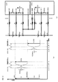
図1は、本発明の第1の実施形態に係る電池監視装置の構成を示す図である。図1に示す電池監視装置1は、蓄電池であるn個のセルBC1〜BCnから構成される組電池2と、電圧検出線L0〜Lnを介して接続されている。電池監視装置1は、組電池2の各セルの正極と負極の間の電圧(セル電圧)を測定するためのセル電圧測定機能と、充電状態の高いセルを放電して各セルの充電状態を均等化するバランシング機能とを有している。なお、図1では、組電池2を構成するセルBC1〜BCnのうち、セルBC1、BCn−1およびBCnのみを図示し、セルBC2〜BCn−2の図示を省略している。ここで、nは1以上の任意の自然数であり、各セルのセル電圧や、組電池2が電力を供給する負荷(不図示)の動作電圧等に応じて決定される。
(First embodiment)
FIG. 1 is a diagram showing a configuration of a battery monitoring apparatus according to the first embodiment of the present invention. A
セルBC1の負極と正極には、セルBC1に対応する一対の電圧検出線L0、L1がそれぞれ接続されている。同様に、セルBCn−1の負極と正極には、セルBCn−1に対応する一対の電圧検出線Ln−2(不図示)、Ln−1がそれぞれ接続されており、セルBCnの負極と正極には、セルBCnに対応する一対の電圧検出線Ln−1、Lnがそれぞれ接続されている。すなわち、組電池2の各セルの正極と負極は、各セルに対応して設けられた一対の電圧検出線を介して電池監視装置1とそれぞれ接続されている。なお、電圧検出線L0、Lnを除いた電圧検出線L1〜Ln−1は、セルBC1〜BCn−1の正極にそれぞれ接続されると共に、隣接するセルBC2〜BCnの負極にもそれぞれ接続されており、これらの各隣接セルの間で共通に用いられる。
A pair of voltage detection lines L0 and L1 corresponding to the cell BC1 are connected to the negative electrode and the positive electrode of the cell BC1, respectively. Similarly, a pair of voltage detection lines Ln-2 (not shown) and Ln-1 corresponding to the cell BCn-1 are connected to the negative electrode and the positive electrode of the cell BCn-1, respectively. Are connected to a pair of voltage detection lines Ln−1 and Ln corresponding to the cell BCn. That is, the positive electrode and the negative electrode of each cell of the assembled battery 2 are connected to the
電池監視装置1には、電圧検出線L0〜Lnにそれぞれ対応して、電圧測定線SL0〜SLnおよび調整線SW0〜SWnが設けられている。各電圧測定線SLn〜SLnと、各調整線SW0〜SWnとは、互いに並列に、各電圧検出線L0〜Lnとそれぞれ接続されている。なお、電圧検出線L0には、電圧測定線SL0および調整線SW0と並列に、電位の基準となるグランド線GNDがさらに接続されている。
The
電池監視装置1は、上記の電圧測定線SL0〜SLnおよび調整線SW0〜SWnに加えて、セルコントローラ10、マイコン20、バランシング抵抗回路30および電圧測定用ノイズフィルタ回路40をさらに備えている。
The
セルコントローラ10は、前述のセル電圧測定機能およびバランシング機能や、各種診断を実現するための電圧測定を行う回路であり、IC(集積回路)等を用いて構成されている。セルコントローラ10は、電圧測定端子Taを介して電圧測定線SL0〜SLnに接続されており、バランシング端子Tbを介して調整線SW0〜SWnに接続されており、グランド端子Tgを介してグランド線GNDに接続されている。セルコントローラ10において、各バランシング端子Tbの間には、各セルの放電を制御するためのバランシングスイッチBSW1〜BSWnが配置されている。
The
なお、図1では、一つのセルコントローラ10のみを図示しているが、電池監視装置1にセルコントローラ10を複数個配置してもよい。その場合、各セルコントローラ10とマイコン20の間の通信は、それぞれ個別で行ってもよいし、デイジーチェーン方式で行ってもよい。たとえば、組電池2のセルを所定個数ごとにグループ化することで、組電池2内に複数のセルグループを設けるようにし、この各セルグループに対してセルコントローラ10を配置することができる。
Although only one
セルコントローラ10は、第一選択回路11、第二選択回路12、第三選択回路13、差動増幅器14、AD変換器15および送受信回路16を有する。
The
第一選択回路11は、セル電圧の測定対象とするセルに対して、当該セルに対応する互いに隣接し合う二つの電圧測定端子Taを選択する。これにより、電圧検出線L0〜Lnを介してセルBC1〜BCnの正極と負極にそれぞれ接続されている電圧測定線SL0〜SLnの中から、当該セルの正極と負極にそれぞれ接続されている一対の電圧測定線を選択する。そして、選択した二つの電圧測定端子Taの電位、すなわち選択した一対の電圧測定線の電位を、第三選択回路13に出力する。
The
第二選択回路12は、互いに隣接し合う二つのバランシング端子Tbを選択する。これにより、電圧検出線L0〜Lnに接続されている調整線SW0〜SWnの中から、断線診断の対象とする一対の電圧検出線にそれぞれ接続されている一対の調整線を選択する。そして、選択した二つのバランシング端子Tbの電位、すなわち選択した一対の調整線の電位を、第三選択回路13に出力する。
The
第三選択回路13は、第一選択回路11または第二選択回路12のいずれか一方を選択し、選択した方の回路において選択されている一対の電圧測定線または調整線の間の電圧を差動増幅器14に出力する。すなわち、第一選択回路11を選択した場合、第三選択回路13は、第一選択回路11において選択されている一対の電圧測定線間の電圧を、測定対象のセル電圧に応じた電圧信号として差動増幅器14に出力する。一方、第二選択回路12を選択した場合、第三選択回路13は、第二選択回路12において選択されている一対の調整線間の電圧を、電圧検出線の断線診断用の電圧信号として差動増幅器14に出力する。
The
差動増幅器14は、第三選択回路13から出力された電圧信号を所定の増幅率で増幅することにより、第三選択回路13からの電圧信号をAD変換器15の入力レンジ内の電圧信号に変換する電圧変換を行い、AD変換器15に出力する。
The
AD変換器15は、第三選択回路13から出力されて差動増幅器14で電圧変換された電圧信号を、所定のAD変換範囲内でアナログ値からデジタル値に変換するための回路である。すなわち、AD変換器15は、第一選択回路11において選択されている一対の電圧測定線間の電圧、または第二選択回路12において選択されている一対の調整線間の電圧を、所定のAD変換範囲内でアナログ値からデジタル値に変換する。これにより、セルコントローラ10において、一対の電圧測定線間の電圧または一対の調整線間の電圧が測定される。
The
送受信回路16は、マイコン20との間で通信を行い、各種の情報を送受信する。たとえば、送受信回路16は、セルコントローラ10の動作内容を示す情報をマイコン20から受信する。これにより、セルコントローラ10は、マイコン20からの指示を受けることができる。また、送受信回路16は、セルコントローラ10において測定された一対の電圧測定線間の電圧または一対の調整線間の電圧をマイコン20に送信する。これにより、セルコントローラ10は、セル電圧または断線診断用電圧の測定結果をマイコン20に出力することができる。
The transmission /
マイコン20は、セルコントローラ10との間で通信を行い、セルコントローラ10の動作を制御する。マイコン20によるセルコントローラ10の制御内容は、上位コントローラ(不図示)等により決定される。
The
バランシング抵抗回路30は、バランシング機能を用いてセルB1〜Bnを放電させるときに調整線SW0〜SWnに流れるバランシング電流を制限するための回路である。バランシング抵抗回路30は、調整線SW0〜SWnにそれぞれ接続されたバランシング抵抗RBにより構成されている。
The balancing
電圧測定用ノイズフィルタ回路40は、電圧測定機能により電圧測定線SL0〜SLnを介して測定されるセルBC1〜BCnのセル電圧からノイズ成分を除去するための回路である。電圧測定用ノイズフィルタ回路40は、電圧測定線SL0〜SLnにそれぞれ接続された抵抗RCと、電圧測定線SL0〜SLnとグランド線GNDの間にそれぞれ接続されたコンデンサCCとにより構成されている。なお、セルBC1〜BCnの電圧を精密に測定できるように、電圧測定用ノイズフィルタ回路40の時定数には、比較的大きな値を設定することが好ましい。
The voltage measurement
次に、電池監視装置1の断線診断方法について説明する。電池監視装置1は、セルコントローラ10において、第二選択回路12により選択された一対の調整線間の電圧を断線診断用電圧として測定し、その測定結果をセルコントローラ10からマイコン20に出力することで、電圧検出線の断線診断を行う。これにより、一対の電圧測定線間の電圧を断線診断用電圧として用いた場合と比べて、断線診断時にバランシングスイッチBSW1〜BSWnをオンする時間を短縮し、電力損失を低減するようにしている。すなわち、一対の電圧測定線間の電圧は、電圧測定用ノイズフィルタ回路40を介して測定されるものであるため、バランシングスイッチのオンオフの切り替えに応じてこの電圧が変化するためには、電圧測定用ノイズフィルタ回路40の時定数に応じた分だけの変化時間を要する。これに対して、一対の調整線間の電圧は、こうしたフィルタを介さずに測定されるものであるため、バランシングスイッチのオンオフの切り替えに応じて素早く変化する。したがって、一対の調整線間の電圧を断線診断用電圧として用いることで、断線診断に要するバランシングスイッチの短絡時間を低減することができる。
Next, the disconnection diagnosis method of the
具体的には、電池監視装置1は、二種類の診断方法のいずれかを用いて、電圧検出線の断線診断を行うことができる。以下では、二種類の診断方法のうち一方を第一の断線診断方法とし、もう一方を第二の断線診断方法として、それぞれ説明する。
Specifically, the
最初に第一の断線診断方法について説明する。第一の断線診断方法では、バランシングスイッチBSW1〜BSWnのいずれかをオンし、このときの当該バランシングスイッチの両端電圧、すなわち当該バランシングスイッチが接続されている一対の調整線間の電圧を、断線診断用電圧として測定する。この断線診断用電圧に基づいて、当該バランシングスイッチに対応するセルの両端に接続されている電圧検出線の断線診断を行う。 First, the first disconnection diagnosis method will be described. In the first disconnection diagnosis method, any one of the balancing switches BSW1 to BSWn is turned on, and the voltage across the balancing switch at this time, that is, the voltage between the pair of adjustment lines to which the balancing switch is connected is determined as a disconnection diagnosis. Measured as a working voltage. Based on the disconnection diagnosis voltage, disconnection diagnosis is performed on the voltage detection lines connected to both ends of the cell corresponding to the balancing switch.
セルBC1〜BCnのいずれかを放電するために、電池監視装置1において対応するバランシングスイッチをオンすると、当該セルの両端に接続されている電圧検出線が正常であれば、当該セルの両端間が電圧検出線および調整線を介して導通され、バランシング電流が流れる。このときのバランシングスイッチの両端電圧、すなわち調整線間の電圧をVとすると、Vの値は以下の式(1)により表される。式(1)において、Iはバランシング電流を表し、Rはバランシングスイッチのオン抵抗値を表している。
V=I×R ・・・(1)
When the corresponding balancing switch is turned on in the
V = I × R (1)
しかし、電圧検出線が断線している場合は、セルBC1〜BCnのいずれかを放電するために対応するバランシングスイッチをオンしても、当該セルの両端間が導通されないため、バランシング電流が流れない。このときのバランシングスイッチの両端電圧、すなわち調整線間の電圧Vは、電流が流れていないために略0となる。 However, when the voltage detection line is disconnected, even if the corresponding balancing switch is turned on to discharge any of the cells BC1 to BCn, the both ends of the cell are not conducted, so that no balancing current flows. . The voltage across the balancing switch at this time, that is, the voltage V between the adjustment lines is substantially zero because no current flows.
以上説明したように、電圧検出線が正常である場合と断線している場合とで、バランシングスイッチがオンであるときの調整線間の電圧に差異が生じる。したがって、第一の断線診断方法では、このバランシングスイッチが閉成状態であるときの一対の調整線間の電圧を断線診断用電圧として測定し、測定した電圧値に基づいて電圧検出線の断線診断を行う。具体的には、たとえば、セルコントローラ10により測定した断線診断用電圧をマイコン20に送信し、その電圧値が所定の閾値以下であるか否かをマイコン20において判断することで、電圧検出線が断線しているか否かを判定することができる。この判定に用いられる閾値は、式(1)で表される正常時の電圧Vよりも小さな値で設定することが好ましい。
As described above, there is a difference in the voltage between the adjustment lines when the balancing switch is on, depending on whether the voltage detection line is normal or disconnected. Therefore, in the first disconnection diagnosis method, the voltage between the pair of adjustment lines when the balancing switch is in the closed state is measured as a disconnection diagnosis voltage, and the disconnection diagnosis of the voltage detection line is performed based on the measured voltage value. I do. Specifically, for example, the disconnection diagnosis voltage measured by the
なお、本実施形態では、AD変換器15として、所定の電圧幅(たとえば5V)のAD変換範囲を有しており、その中心電圧を複数の電圧の中から選択することで、AD変換範囲を切り替え可能なAD変換器を使用することができる。この場合、上記のように調整線間の電圧を断線診断用電圧として測定する際には、測定精度を確保するために、AD変換器15のAD変換範囲をセル電圧の測定時から切り替えることが好ましい。この点について、図2に示すAD変換器15の入力レンジと電圧検出誤差の関係例を参照して、以下に説明する。
In the present embodiment, the
図2(a)は、AD変換器15のAD変換範囲が0V〜5Vの場合の入力レンジと電圧検出誤差の関係の一例を示している。図2(a)に示すように、AD変換範囲が0V〜5Vの場合は、その中心電圧の2.5V付近で電圧検出誤差が最小となり、0Vや5Vに近づくほど電圧検出誤差が大きくなる。したがって、一対の電圧測定線間の電圧をセル電圧として測定する際には、差動増幅器14による電圧変換後のセル電圧が図2(a)に示す電圧範囲内となるように、AD変換器15のAD変換範囲を0V〜5Vに設定することが好ましい。
FIG. 2A shows an example of the relationship between the input range and the voltage detection error when the AD conversion range of the
図2(b)は、AD変換器15のAD変換範囲が−2.5V〜2.5Vの場合の入力レンジと電圧検出誤差の関係の一例を示している。図2(b)に示すように、AD変換範囲が−2.5V〜2.5Vの場合は、その中心電圧の0V付近で電圧検出誤差が最小となり、−2.5Vや2.5Vに近づくほど電圧検出誤差が大きくなる。したがって、一対の調整線間の電圧を断線診断用電圧として測定する際には、差動増幅器14による電圧変換後の断線診断用電圧が図2(b)に示す電圧範囲内となるように、AD変換器15のAD変換範囲を−2.5V〜2.5Vに設定することが好ましい。
FIG. 2B shows an example of the relationship between the input range and the voltage detection error when the AD conversion range of the
以上説明したように、一対の電圧測定線間の電圧をセル電圧として測定する場合と、一対の調整線間の電圧を断線診断用電圧として測定する場合とで、それぞれの電圧範囲に応じてAD変換器15のAD変換範囲を変化させることが好ましい。これにより、断線診断用電圧の測定結果に基づいて、電圧検出線の正常時と断線時の違いを確実に検知することができる。その結果、断線診断をより一層正確に行うことができる。
As described above, when the voltage between the pair of voltage measurement lines is measured as a cell voltage, and when the voltage between the pair of adjustment lines is measured as a disconnection diagnosis voltage, AD is determined depending on each voltage range. It is preferable to change the AD conversion range of the
続いて第二の断線診断方法について説明する。第二の断線診断方法では、バランシングスイッチBSW1〜BSWnのいずれかを所定の短絡時間だけオンした後にオフし、それから所定の待機時間を経過したときの当該バランシングスイッチの両端電圧、すなわち当該バランシングスイッチが接続されている一対の調整線間の電圧を、断線診断用電圧として測定する。この断線診断用電圧に基づいて、当該バランシングスイッチに対応するセルの両端に接続されている電圧検出線の断線診断を行う。 Next, the second disconnection diagnosis method will be described. In the second disconnection diagnosis method, any one of the balancing switches BSW1 to BSWn is turned on after being turned on for a predetermined short-circuit time, and the voltage across the balancing switch when the predetermined standby time has elapsed, that is, the balancing switch is The voltage between the pair of connected adjustment lines is measured as a disconnection diagnosis voltage. Based on the disconnection diagnosis voltage, disconnection diagnosis is performed on the voltage detection lines connected to both ends of the cell corresponding to the balancing switch.
前述の第一の断線診断方法では、式(1)に示したバランシングスイッチのオン抵抗値Rが小さいと、得られる電圧Vの値が0に近くなるため、電圧検出線が断線しているか否かを正確に診断するのが困難となる。これは、バランシングスイッチのオン抵抗値Rを大きくしたり、セルコントローラ10内にバランシングスイッチと直列に抵抗を配置したりすることで解消できるが、これらの措置はセルコントローラ10の発熱を引き起こし、セルコントローラ10の誤作動や故障につながるおそれがある。また、セルコントローラ10の放熱を効率的に行うための放熱機構が必要となり、電池監視装置1の構造を複雑化してしまうという弊害もある。
In the first disconnection diagnosis method described above, if the on-resistance value R of the balancing switch shown in the equation (1) is small, the value of the obtained voltage V is close to 0, so whether or not the voltage detection line is disconnected. It is difficult to accurately diagnose this. This can be solved by increasing the on-resistance value R of the balancing switch or by placing a resistor in series with the balancing switch in the
そこで、第二の断線診断方法では、バランシングスイッチの開閉に伴って変化する一対の調整線間の電圧を測定する。これにより、バランシングスイッチのオン抵抗値Rが小さい場合であっても、電圧検出線が断線しているか否かを正確に診断できるようにする。 Therefore, in the second disconnection diagnosis method, the voltage between the pair of adjustment lines that changes as the balancing switch is opened and closed is measured. Thereby, even when the on-resistance value R of the balancing switch is small, it is possible to accurately diagnose whether or not the voltage detection line is disconnected.
たとえば、セルBC1〜BCnのいずれかを放電するために、電池監視装置1において対応するバランシングスイッチをオフからオンに切り替えたとする。このとき、当該セルの両端に電圧検出線を介して接続されている一対の調整線間の電圧は、当該セルのセル電圧から前述の式(1)で求められる電圧Vへと変化する。その後、バランシングスイッチを再びオフにすると、電圧検出線が正常であれば速やかに元のセル電圧へと戻るが、電圧検出線が断線している場合は、周辺回路に応じて決定される時定数に応じて比較的ゆっくりと変化する。
For example, it is assumed that the corresponding balancing switch in the
上記のように、電圧検出線が正常である場合と断線している場合とで、バランシングスイッチをオンした後にオフしたときの調整線間の電圧変化速度に差異が生じる。したがって、第二の断線診断方法では、バランシングスイッチを閉じて開いてから所定の待機時間経過後の一対の調整線間の電圧を断線診断用電圧として測定し、測定した電圧値に基づいて電圧検出線の断線診断を行う。具体的には、たとえば、セルコントローラ10により測定した断線診断用電圧をマイコン20に送信し、その電圧値とセル電圧との差が所定の閾値以下であるか否かをマイコン20において判断することで、電圧検出線が断線しているか否かを判定することができる。
As described above, there is a difference in the voltage change speed between the adjustment lines when the voltage detection line is normal and when the voltage detection line is disconnected, when the balancing switch is turned on and then turned off. Therefore, in the second disconnection diagnosis method, the voltage between the pair of adjustment lines after a predetermined waiting time has elapsed after the balancing switch is closed and opened is measured as a disconnection diagnosis voltage, and voltage detection is performed based on the measured voltage value. Perform wire breakage diagnosis. Specifically, for example, the disconnection diagnosis voltage measured by the
なお、第二の断線診断方法においても、第一の断線診断方法で説明したように、一対の電圧測定線間の電圧をセル電圧として測定する場合と、一対の調整線間の電圧を断線診断用電圧として測定する場合とで、それぞれの電圧範囲に応じてAD変換器15のAD変換範囲を変化させてもよい。このとき、第一の断線診断方法におけるAD変換範囲と、第二の断線診断方法におけるAD変換範囲とを、それぞれ別のものとしてもよい。
In the second disconnection diagnosis method, as described in the first disconnection diagnosis method, the voltage between the pair of voltage measurement lines is measured as a cell voltage, and the voltage between the pair of adjustment lines is diagnosed. Depending on the voltage range, the AD conversion range of the
次に、第一の断線診断方法および第二の断線診断方法の詳細について、図3および図4を参照して以下に説明する。図3は、電圧検出線が正常である場合の各調整線の電位変動の様子を示す図であり、図4は、電圧検出線が断線した場合の各調整線の電位変動の様子を示す図である。なお、図3、4では、複数のセルコントローラ10が直列に接続されており、そのうち互いに隣接する2つのセルコントローラ10の境界部分での挙動を例示している。
Next, details of the first disconnection diagnosis method and the second disconnection diagnosis method will be described below with reference to FIGS. 3 and 4. FIG. 3 is a diagram illustrating a state of potential fluctuation of each adjustment line when the voltage detection line is normal, and FIG. 4 is a diagram illustrating a state of potential variation of each adjustment line when the voltage detection line is disconnected. It is. 3 and 4, a plurality of
図3(b)、図4(b)に示すように、一方のセルコントローラ10は、上位側(高電位側)にあるセルBC1、BC2に接続されている。この上位側のセルコントローラ10において、セルBC1に対応する一対の調整線SW0、SW1間の電圧をV1とする。また、もう一方のセルコントローラ10は、下位側(低電位側)にあるセルBC11、BC12に接続されている。この下位側のセルコントローラ10において、セルBC12に対応する一対の調整線SW11、SW12間の電圧をV12とする。
As shown in FIGS. 3B and 4B, one
電圧検出線が正常である場合は、図3(a)に示すように、時刻t1_onにおいてセルBC1に対応するバランシングスイッチBSW1をオンにすると、調整線SW0の電位が上昇すると共に、調整線SW1の電位が低下する。そして、調整線SW0、SW1間の時定数に応じて定まる所定の変動時間を経過すると、これらの電位が一定となる。このときの調整線SW0、SW1間の電圧V1(on)は、バランシングスイッチBSW1のオン抵抗値に応じて、前述の式(1)により決定される。 When the voltage detection line is normal, as shown in FIG. 3A, when the balancing switch BSW1 corresponding to the cell BC1 is turned on at time t1_on, the potential of the adjustment line SW0 rises and the adjustment line SW1 The potential drops. Then, when a predetermined fluctuation time determined according to the time constant between the adjustment lines SW0 and SW1 has elapsed, these potentials become constant. The voltage V1 (on) between the adjustment lines SW0 and SW1 at this time is determined by the above-described equation (1) according to the on-resistance value of the balancing switch BSW1.
同様に、時刻t2_onにおいてセルBC12に対応するバランシングスイッチBSW12をオンにすると、調整線SW11の電位が上昇すると共に、調整線SW12の電位が低下する。そして、調整線SW11、SW12間の時定数に応じて定まる所定の変動時間を経過すると、これらの電位が一定となる。このときの調整線SW11、SW12間の電圧V12(on)は、バランシングスイッチBSW12のオン抵抗値に応じて、前述の式(1)により決定される。 Similarly, when the balancing switch BSW12 corresponding to the cell BC12 is turned on at time t2_on, the potential of the adjustment line SW11 increases and the potential of the adjustment line SW12 decreases. Then, when a predetermined fluctuation time determined according to the time constant between the adjustment lines SW11 and SW12 elapses, these potentials become constant. The voltage V12 (on) between the adjustment lines SW11 and SW12 at this time is determined by the above-described equation (1) according to the on-resistance value of the balancing switch BSW12.
一方、図4(b)に示すように、調整線SW0およびSW12と接続されている電圧検出線L0が断線していたとする。この場合は、図4(a)に示すように、時刻t1_onにおいてセルBC1に対応するバランシングスイッチBSW1をオンにすると、調整線SW0の電位は上昇するが、調整線SW1の電位は変化しない。そして、所定の変動時間を経過すると、これらの電位が略一致する。このときの調整線SW0、SW1間の電圧V1(on)は、電圧検出線L0の断線によりバランシング電流が流れないことから、前述のように略0となる。 On the other hand, as shown in FIG. 4B, it is assumed that the voltage detection line L0 connected to the adjustment lines SW0 and SW12 is disconnected. In this case, as shown in FIG. 4A, when the balancing switch BSW1 corresponding to the cell BC1 is turned on at time t1_on, the potential of the adjustment line SW0 rises, but the potential of the adjustment line SW1 does not change. Then, when a predetermined fluctuation time elapses, these potentials substantially coincide. At this time, the voltage V1 (on) between the adjustment lines SW0 and SW1 is substantially 0 as described above because the balancing current does not flow due to the disconnection of the voltage detection line L0.
同様に、時刻t2_onにおいてセルBC12に対応するバランシングスイッチBSW12をオンにすると、調整線SW12の電位は低下するが、調整線SW11の電位は変化しない。そして、所定の変動時間を経過すると、これらの電位が略一致する。このときの調整線SW11、SW12間の電圧V12(on)は、電圧検出線L0の断線によりバランシング電流が流れないことから、前述のように略0となる。 Similarly, when the balancing switch BSW12 corresponding to the cell BC12 is turned on at time t2_on, the potential of the adjustment line SW12 decreases, but the potential of the adjustment line SW11 does not change. Then, when a predetermined fluctuation time elapses, these potentials substantially coincide. At this time, the voltage V12 (on) between the adjustment lines SW11 and SW12 is substantially zero as described above because the balancing current does not flow due to the disconnection of the voltage detection line L0.
第一の断線診断方法では、以上説明したような正常時と断線時での電圧V1(on)、V12(on)の違いを利用して、電圧検出線L0の断線診断を行う。すなわち、セルBC1、BC12に対応するバランシングスイッチBSW1、BSW12をそれぞれオンしたときの電圧V1(on)、V12(on)を断線診断用電圧としてそれぞれ測定し、これらの測定値が略0であるか否かをそれぞれ判定することで、セルBC1およびBC12に接続されている電圧検出線L0の断線診断を行うことができる。 In the first disconnection diagnosis method, the disconnection diagnosis of the voltage detection line L0 is performed using the difference between the voltages V1 (on) and V12 (on) between the normal time and the disconnection time as described above. That is, voltages V1 (on) and V12 (on) when the balancing switches BSW1 and BSW12 corresponding to the cells BC1 and BC12 are turned on are measured as disconnection diagnosis voltages, respectively, and whether these measured values are substantially zero. By determining whether or not each, it is possible to diagnose disconnection of the voltage detection line L0 connected to the cells BC1 and BC12.
また、電圧検出線L0が正常である場合は、図3(a)に示すように、バランシングスイッチBSW1をオンにした後、時刻t1_offにおいてバランシングスイッチBSW1をオフにすると、調整線SW0の電位が低下すると共に、調整線SW1の電位が上昇する。そして、オン時と同様の変動時間を経過すると、これらの電位は、バランシングスイッチBSW1をオンする前の状態へとそれぞれ戻る。このときの調整線SW0、SW1間の電圧は、セルBC1のセル電圧を表している。なお、時刻t1_onから時刻t1_offまでの時間、すなわちバランシングスイッチBSW1の短絡時間は、上記の変動時間よりも長く設定することが好ましい。 When the voltage detection line L0 is normal, as shown in FIG. 3A, after the balancing switch BSW1 is turned on, when the balancing switch BSW1 is turned off at time t1_off, the potential of the adjustment line SW0 decreases. At the same time, the potential of the adjustment line SW1 rises. And when the same fluctuation time as at the time of ON passes, these electric potentials will each return to the state before turning ON balancing switch BSW1. The voltage between the adjustment lines SW0 and SW1 at this time represents the cell voltage of the cell BC1. Note that the time from time t1_on to time t1_off, that is, the short-circuit time of the balancing switch BSW1, is preferably set longer than the above-described fluctuation time.
ここで、バランシングスイッチBSW1をオフにしてから所定の待機時間Twを経過したときの時刻t1における調整線SW0、SW1間の電圧V1(t1)を測定すると、この電圧V1(t1)は、時刻t1_on以前の電圧V1、すなわちセルBC1のセル電圧にほぼ等しくなる。なお、待機時間Twは、上記の変動時間よりも長い値を設定することが好ましい。 Here, when the voltage V1 (t1) between the adjustment lines SW0 and SW1 at time t1 when a predetermined standby time Tw has elapsed after turning off the balancing switch BSW1, the voltage V1 (t1) is obtained at time t1_on. It becomes approximately equal to the previous voltage V1, that is, the cell voltage of the cell BC1. Note that the standby time Tw is preferably set to a value longer than the above fluctuation time.
同様に、バランシングスイッチBSW12をオンにした後、時刻t2_offにおいてバランシングスイッチBSW12をオフにすると、調整線SW11の電位が低下すると共に、調整線SW12の電位が上昇する。そして、オン時と同様の変動時間を経過すると、これらの電位は、バランシングスイッチBSW12をオンする前の状態へとそれぞれ戻る。このときの調整線SW11、SW12間の電圧は、セルBC12のセル電圧を表している。その後、バランシングスイッチBSW1をオフにしてから所定の待機時間Twを経過したときの時刻t2における調整線SW11、SW12間の電圧V12(t2)を測定すると、この電圧V12(t2)は、時刻t2_on以前の電圧V12、すなわちセルBC12のセル電圧にほぼ等しくなる。 Similarly, when the balancing switch BSW12 is turned off at time t2_off after the balancing switch BSW12 is turned on, the potential of the adjustment line SW11 is lowered and the potential of the adjustment line SW12 is raised. And when the same fluctuation time as at the time of ON passes, these electric potentials will each return to the state before turning ON the balancing switch BSW12. The voltage between the adjustment lines SW11 and SW12 at this time represents the cell voltage of the cell BC12. Thereafter, when the voltage V12 (t2) between the adjustment lines SW11 and SW12 at time t2 when a predetermined standby time Tw has elapsed since turning off the balancing switch BSW1, this voltage V12 (t2) is measured before time t2_on. Voltage V12, that is, approximately equal to the cell voltage of the cell BC12.
一方、図4(b)に示すように、調整線SW0およびSW12と接続されている電圧検出線L0が断線している場合は、バランシングスイッチBSW1をオンにした後、時刻t1_offにおいてバランシングスイッチBSW1をオフにすると、調整線SW0の電位はフローティング状態となる。そのため、時刻t1_off後の調整線SW0の電位は、たとえば図4(a)において符号41、42または43のいずれかに示すように、正常時と比べてゆっくりと低下する。したがって、時刻t1における調整線SW0、SW1間の電圧V1(t1)は、正常時と比べて低くなる。
On the other hand, as shown in FIG. 4B, when the voltage detection line L0 connected to the adjustment lines SW0 and SW12 is disconnected, the balancing switch BSW1 is turned on and then the balancing switch BSW1 is turned on at time t1_off. When turned off, the potential of the adjustment line SW0 is in a floating state. For this reason, the potential of the adjustment line SW0 after time t1_off gradually decreases as compared with the normal time, as indicated by any of
同様に、バランシングスイッチBSW12をオンにした後、時刻t2_offにおいてバランシングスイッチBSW12をオフにすると、調整線SW12の電位はフローティング状態となる。そのため、時刻t2_off後の調整線SW12の電位についても、たとえば符号41、42または43のいずれかに示すように、正常時と比べてゆっくりと低下する。したがって、時刻t2における調整線SW11、SW12間の電圧V12(t2)は、正常時と比べて低くなる。
Similarly, when the balancing switch BSW12 is turned off at time t2_off after the balancing switch BSW12 is turned on, the potential of the adjustment line SW12 is in a floating state. For this reason, the potential of the adjustment line SW12 after time t2_off also decreases slowly as compared with the normal time, as indicated by, for example, any one of
第二の断線診断方法では、以上説明したような正常時と断線時での電圧V1(t1)、V12(t2)の違いを利用して、電圧検出線L0の断線診断を行う。すなわち、セルBC1、BC12に対応するバランシングスイッチBSW1、BSW12をそれぞれ所定の短絡時間だけオンしてからオフし、その後に所定の経過時間を経過したときの時刻t1、t2における電圧V1(t1)、V12(t2)を断線診断用電圧としてそれぞれ測定する。そして、これらの測定値と、セルBC1、BC12の各セル電圧とをそれぞれ比較することで、セルBC1およびBC12に接続されている電圧検出線L0の断線診断を行うことができる。なお、セルBC1、BC12の各セル電圧は、バランシングスイッチBSW1、BSW12をそれぞれオンする前の電圧V1、V12の測定値を用いてもよいし、前述のセル電圧測定機能を用いて測定した値を用いてもよい。 In the second disconnection diagnosis method, the disconnection diagnosis of the voltage detection line L0 is performed using the difference between the voltages V1 (t1) and V12 (t2) between the normal time and the disconnection as described above. That is, voltages V1 (t1) at times t1 and t2 when the balancing switches BSW1 and BSW12 corresponding to the cells BC1 and BC12 are turned on after being turned on for a predetermined short circuit time and then passed for a predetermined elapsed time, V12 (t2) is measured as a disconnection diagnosis voltage. And the disconnection diagnosis of the voltage detection line L0 connected to the cells BC1 and BC12 can be performed by comparing these measured values with the cell voltages of the cells BC1 and BC12. The cell voltages of the cells BC1 and BC12 may be measured values of the voltages V1 and V12 before the balancing switches BSW1 and BSW12 are turned on, respectively, or values measured using the cell voltage measuring function described above. It may be used.
以上説明したように、第二の断線診断方法では、正常時と異常時で電圧値が大きく変化する電圧V1(t1)、V12(t2)を用いて、電圧検出線L0の断線診断を行う。そのため、正常時と異常時の差が比較的小さい電圧V1(on)、V12(on)を用いる第一の断線診断方法と比べて、診断能力を向上させることができる。 As described above, in the second disconnection diagnosis method, the disconnection diagnosis of the voltage detection line L0 is performed using the voltages V1 (t1) and V12 (t2) whose voltage values greatly change between normal time and abnormal time. Therefore, compared with the 1st disconnection diagnostic method using voltage V1 (on) and V12 (on) with a comparatively small difference between the normal time and the abnormal time, the diagnostic ability can be improved.
なお、上記の断線時における調整線の電位低下の早さは、断線部位の周辺回路の状況に応じて変化する。図4(b)に示すように電圧検出線L0が断線した場合、この電圧検出線L0は、調整線SW0およびSW12の他に、上位側のセルコントローラ10のグランド線GNDや、下位側のセルコントローラ10の電源端子に接続された電源ラインとも共用されている。したがってこの場合、バランシングスイッチBSW1をオフした後の調整線SW0の電位変化の早さや、バランシングスイッチBSW12をオフした後の調整線SW12の電位変化の早さは、主にセルコントローラ10の消費電流経路における電流やインピーダンスの大きさ等に応じて決定されることとなる。一方、他の電圧検出線、たとえば調整線SW1と接続されている電圧検出線L1が断線した場合は、主にセルコントローラ10内のリーク電流等に応じて、電圧検出線L1に接続されている調整線SW1の電位変化の早さが決定される。そのため、図4(b)に示す断線部位の場合は、他の断線部位の場合と比べて、調整線SW0や調整線SW12の電位が比較的早く低下することになり、正常時と異常時の判別が困難になることがある。
Note that the speed of the potential drop of the adjustment line at the time of disconnection varies depending on the state of the peripheral circuit at the disconnection site. When the voltage detection line L0 is disconnected as shown in FIG. 4B, the voltage detection line L0 is connected to the ground line GND of the
そこで、第二の断線診断方法では、図4(b)の断線部位に対応する電圧V1(t1)および電圧V12(t2)の両方を用いて、電圧検出線L0の断線診断を行ってもよい。具体的には、以下の式(2)により算出される電圧値Vd0に基づいて、セルBC1とセルBC12の間に接続されている電圧検出線L0が断線しているか否かを判断することができる。式(2)の電圧値Vd0は、電圧V1(t1)と電圧V12(t2)とを合計した電圧和V1(t1)+V12(t2)を求め、セルBC1のセル電圧V1とセルBC12のセル電圧V12との合計値であるV1+V12から、この電圧和V1(t1)+V12(t2)を減算した値を表している。式(2)で求められた電圧値Vd0が略0であれば、電圧検出線L0が正常と判断し、そうでない場合は異常、すなわち断線ありと判断することができる。
Vd0=V1+V12−{V1(t1)+V12(t2)} ・・・(2)
Therefore, in the second disconnection diagnosis method, the disconnection diagnosis of the voltage detection line L0 may be performed using both the voltage V1 (t1) and the voltage V12 (t2) corresponding to the disconnection site in FIG. . Specifically, it is possible to determine whether or not the voltage detection line L0 connected between the cell BC1 and the cell BC12 is disconnected based on the voltage value Vd0 calculated by the following equation (2). it can. The voltage value Vd0 in the equation (2) is obtained by calculating a voltage sum V1 (t1) + V12 (t2) obtained by summing up the voltage V1 (t1) and the voltage V12 (t2). This is a value obtained by subtracting the voltage sum V1 (t1) + V12 (t2) from V1 + V12 which is the total value with V12. If the voltage value Vd0 obtained by the equation (2) is approximately 0, it can be determined that the voltage detection line L0 is normal, and if not, it can be determined that there is an abnormality, that is, there is a disconnection.
Vd0 = V1 + V12− {V1 (t1) + V12 (t2)} (2)
第二の断線診断方法では、以上説明したような診断方法により、さらに診断能力を向上させることができる。 In the second disconnection diagnostic method, the diagnostic ability can be further improved by the diagnostic method described above.
以上説明した本発明の第1の実施形態によれば、以下の作用効果を奏する。 According to the 1st Embodiment of this invention demonstrated above, there exist the following effects.
(1)電池監視装置1は、セルBC1の正極と負極にそれぞれ接続された一対の電圧検出線L1、L0とそれぞれ接続された一対の電圧測定線SL1、SL0と、この電圧測定線SL1、SL0と並列に、一対の電圧検出線L1、L0とそれぞれ接続された一対の調整線SW1、SW0と、この一対の調整線SW1、SW0の間に接続されたバランシングスイッチBSW1とを備える。そして、一対の調整線SW1、SW0間の電圧V1に基づいて、電圧検出線L0の断線を診断する。このようにしたので、電圧検出線L0の断線診断を行うのに必要なバランシングスイッチBSW1の短絡時間を短縮し、電力損失を低減することができる。
(1) The
(2)電池監視装置1は、第一の断線診断方法を用いて、電圧検出線L0の断線診断を行うことができる。この第一の断線診断方法では、バランシングスイッチBSW1が閉成状態であるときの一対の調整線SW1、SW0間の電圧V1(on)に基づいて、電圧検出線L0の断線を診断する。このようにしたので、正常時と断線時での電圧V1(on)の違いが比較的大きい場合は、容易に断線診断を行うことができる。
(2) The
(3)また、電池監視装置1は、第二の断線診断方法を用いて、電圧検出線L0の断線診断を行うこともできる。この第二の断線診断方法では、バランシングスイッチBSW1を閉じて開いてから所定の待機時間Twを経過したときの一対の調整線SW1、SW0間の電圧V1(t1)に基づいて、電圧検出線L0の断線を診断する。このようにしたので、正常時と断線時での電圧V1(on)の違いが比較的小さいときでも、確実に断線診断を行うことができる。
(3) Moreover, the
(4)電池監視装置1は、電圧測定線SL1、SL0に接続された電圧測定用ノイズフィルタ回路40を備える。そのため、セルBC1のセル電圧の測定値からノイズを除去して、セル電圧を正確に測定することができる。
(4) The
(5)電池監視装置1は、複数対の調整線および複数対のバランシングスイッチを備える。複数対の調整線は、直列に接続された2つのセルBC1、BC12のうち上位のセルBC1の正極に接続された電圧検出線L1と接続された調整線SW1と、下位のセルBC12の正極および上位のセルBC1の負極に接続された電圧検出線L0とそれぞれ接続された調整線SW0およびSW12と、下位のセルBC12の負極に接続された電圧検出線L11と接続された調整線SW11とを含む。また、複数のバランシングスイッチは、調整線SW1と調整線SW0の間に接続されたバランシングスイッチBSW1と、調整線SW12と調整線SW11の間に接続されたバランシングスイッチBSW12とを含む。この電池監視装置1は、第二の断線診断方法において、バランシングスイッチBSW1を閉じて開いてから待機時間Twを経過したときの調整線SW1と調整線SW0間の電圧V1(t1)と、バランシングスイッチBSW12を閉じて開いてから待機時間Twを経過したときの調整線SW12と調整線SW11間の電圧V12(t2)とを合計した電圧和V1(t1)+V12(t2)を求め、上位のセルBC1のセル電圧V1と下位のセルBC12のセル電圧V12との合計値V1+V12からこの電圧和V1(t1)+V12(t2)を減算した値Vd0に基づいて、電圧検出線L0の断線を診断することができる。このようにしたので、断線診断をより一層正確に行うことができる。
(5) The
(6)電池監視装置1は、一対の電圧測定線間の電圧または一対の調整線間の電圧を所定のAD変換範囲内でアナログ値からデジタル値に変換するAD変換器15を備える。このAD変換器15は、一対の電圧測定線間の電圧を変換する場合と、一対の調整線間の電圧を変換する場合とで、AD変換範囲を変化させるようにしてもよい。このようにすれば、断線診断をより一層正確に行うことができる。
(6) The
(第2の実施形態)
次に本発明の第2の実施形態について説明する。図5は、本発明の第2の実施形態に係る電池監視装置の構成を示す図である。図5に示す電池監視装置1aは、図1に示した第1の実施形態に係る電池監視装置1と比べて、バランシング抵抗回路30に替えてバランシング用ノイズフィルタ回路30aを備える点が異なっている。
(Second Embodiment)
Next, a second embodiment of the present invention will be described. FIG. 5 is a diagram showing a configuration of a battery monitoring apparatus according to the second embodiment of the present invention. The
バランシング用ノイズフィルタ回路30aは、図1のバランシング抵抗回路30と同様に、調整線SW0〜SWnにそれぞれ接続されたバランシング抵抗RBを有している。さらに、バランシング抵抗RBに加えて、調整線SW0〜SWnのうち互いに隣接するもの同士の間にそれぞれ接続されたコンデンサCBを有している。このバランシング抵抗RBおよびコンデンサCBにより、各調整線間の電圧を断線診断用電圧として測定する際に、ノイズ成分を除去して測定を行うことができる。
The balancing noise filter circuit 30a has balancing resistors RB connected to the adjustment lines SW0 to SWn, respectively, similarly to the balancing
ここで、電圧測定用ノイズフィルタ回路40の時定数は、ノイズを効果的に除去してセル電圧を精密に測定できるように、比較的大きく設定する必要がある。一方、断線診断用電圧の測定には、セル電圧の測定ほどの精密さは不要であるため、バランシング用ノイズフィルタ回路30aの時定数は、電圧測定用ノイズフィルタ回路40に比べて非常に小さくすることが可能である。また、断線診断時にバランシングスイッチをオンする時間を短縮して電力損失を低減するためにも、バランシング用ノイズフィルタ回路30aの時定数はなるべく小さいほうが好ましい。そのため、第2の実施形態では、電圧測定用ノイズフィルタ回路40の時定数がバランシング用ノイズフィルタ回路30aの時定数よりも大きくなるように、バランシング用ノイズフィルタ回路30aの時定数を設定することが好ましい。このようにすれば、セル電圧の測定と断線診断用電圧の測定とを、それぞれ効果的に行うことができる。
Here, the time constant of the
なお、以上では種々の実施の形態および変形例を説明したが、本発明はこれらの内容に限定されるものではない。本発明の技術的思想の範囲内で考えられるその他の態様も本発明の範囲内に含まれる。 Although various embodiments and modifications have been described above, the present invention is not limited to these contents. Other embodiments conceivable within the scope of the technical idea of the present invention are also included in the scope of the present invention.
1、1a:電池監視装置、2:組電池、10:セルコントローラ、11:第一選択回路、12:第二選択回路、13:第三選択回路、14:差動増幅器、15:AD変換器、16:送受信回路、20:マイコン、30:バランシング抵抗回路、30a:バランシング用ノイズフィルタ回路、40:電圧測定用ノイズフィルタ回路 1, 1a: battery monitoring device, 2: assembled battery, 10: cell controller, 11: first selection circuit, 12: second selection circuit, 13: third selection circuit, 14: differential amplifier, 15: AD converter 16: transmitter / receiver circuit, 20: microcomputer, 30: balancing resistor circuit, 30a: noise filter circuit for balancing, 40: noise filter circuit for voltage measurement
Claims (7)
前記電圧測定線と並列に、前記一対の電圧検出線とそれぞれ接続された一対の調整線と、
前記一対の調整線の間に接続されたスイッチと、を備え、
前記一対の調整線間の電圧に基づいて、前記電圧検出線の断線を診断することを特徴とする電池監視装置。 A pair of voltage detection lines connected to a positive electrode and a negative electrode of the storage battery, respectively, and a pair of voltage measurement lines connected to each other;
In parallel with the voltage measurement line, a pair of adjustment lines respectively connected to the pair of voltage detection lines,
A switch connected between the pair of adjustment lines,
A battery monitoring device that diagnoses disconnection of the voltage detection line based on a voltage between the pair of adjustment lines.
前記スイッチは所定のオン抵抗を有しており、
前記スイッチが閉成状態であるときの前記一対の調整線間の電圧に基づいて、前記電圧検出線の断線を診断することを特徴とする電池監視装置。 The battery monitoring device according to claim 1,
The switch has a predetermined on-resistance,
A battery monitoring apparatus characterized by diagnosing disconnection of the voltage detection line based on a voltage between the pair of adjustment lines when the switch is in a closed state.
前記スイッチを閉じて開いてから所定の待機時間を経過したときの前記一対の調整線間の電圧に基づいて、前記電圧検出線の断線を診断することを特徴とする電池監視装置。 The battery monitoring device according to claim 1 or 2,
A battery monitoring device characterized by diagnosing disconnection of the voltage detection line based on a voltage between the pair of adjustment lines when a predetermined standby time has elapsed since the switch was closed and opened.
前記電圧測定線に接続された第一のノイズフィルタをさらに備えることを特徴とする電池監視装置。 The battery monitoring device according to claim 3,
The battery monitoring apparatus further comprising a first noise filter connected to the voltage measurement line.
前記調整線に接続された第二のノイズフィルタをさらに備え、
前記第一のノイズフィルタの時定数は、前記第二のノイズフィルタの時定数よりも大きいことを特徴とする電池監視装置。 The battery monitoring device according to claim 4,
A second noise filter connected to the adjustment line;
The battery monitoring device, wherein a time constant of the first noise filter is larger than a time constant of the second noise filter.
複数対の前記調整線および複数の前記スイッチを備え、
前記複数対の調整線は、直列に接続された2つの前記蓄電池のうち上位の蓄電池の正極に接続された第一の電圧検出線と接続された第一の調整線と、前記2つの蓄電池のうち下位の蓄電池の正極および前記上位の蓄電池の負極に接続された第二の電圧検出線とそれぞれ接続された第二の調整線および第三の調整線と、前記下位の蓄電池の負極に接続された第三の電圧検出線と接続された第四の調整線と、を含み、
前記複数のスイッチは、前記第一の調整線と前記第二の調整線の間に接続された第一のスイッチと、前記第三の調整線と前記第四の調整線の間に接続された第二のスイッチと、を含み、
前記第一のスイッチを閉じて開いてから前記待機時間を経過したときの前記第一の調整線と前記第二の調整線の間の電圧と、前記第二のスイッチを閉じて開いてから前記待機時間を経過したときの前記第三の調整線と前記第四の調整線の間の電圧とを合計した電圧和を求め、
前記上位の蓄電池の電圧と前記下位の蓄電池の電圧との合計値から前記電圧和を減算した値に基づいて、前記第二の電圧検出線の断線を診断することを特徴とする電池監視装置。 The battery monitoring device according to any one of claims 3 to 5,
A plurality of pairs of adjustment lines and a plurality of the switches;
The plurality of pairs of adjustment lines include a first adjustment line connected to a first voltage detection line connected to a positive electrode of a higher-order storage battery among the two storage batteries connected in series, and the two storage batteries. The second adjustment line and the third adjustment line connected to the positive electrode of the lower storage battery and the second voltage detection line connected to the negative electrode of the upper storage battery, respectively, and the negative electrode of the lower storage battery. And a fourth adjustment line connected to the third voltage detection line,
The plurality of switches are connected between the first adjustment line and the second adjustment line, and between the third adjustment line and the fourth adjustment line. A second switch, and
The voltage between the first adjustment line and the second adjustment line when the standby time has elapsed since the first switch was closed and opened, and after the second switch was closed and opened, the Find the voltage sum of the sum of the voltage between the third adjustment line and the fourth adjustment line when the standby time has elapsed,
A battery monitoring device that diagnoses disconnection of the second voltage detection line based on a value obtained by subtracting the voltage sum from a total value of the voltage of the upper storage battery and the voltage of the lower storage battery.
前記一対の電圧測定線間の電圧または前記一対の調整線間の電圧を所定のAD変換範囲内でアナログ値からデジタル値に変換するAD変換器をさらに備え、
前記AD変換器は、前記一対の電圧測定線間の電圧を変換する場合と、前記一対の調整線間の電圧を変換する場合とで、前記AD変換範囲を変化させることを特徴とする電池監視装置。 The battery monitoring device according to any one of claims 1 to 6,
An AD converter that converts the voltage between the pair of voltage measurement lines or the voltage between the pair of adjustment lines from an analog value to a digital value within a predetermined AD conversion range;
The AD converter changes the AD conversion range between a case where the voltage between the pair of voltage measurement lines is converted and a case where the voltage between the pair of adjustment lines is converted. apparatus.
Priority Applications (1)
| Application Number | Priority Date | Filing Date | Title |
|---|---|---|---|
| JP2014102502A JP6192588B2 (en) | 2014-05-16 | 2014-05-16 | Battery monitoring device |
Applications Claiming Priority (1)
| Application Number | Priority Date | Filing Date | Title |
|---|---|---|---|
| JP2014102502A JP6192588B2 (en) | 2014-05-16 | 2014-05-16 | Battery monitoring device |
Publications (2)
| Publication Number | Publication Date |
|---|---|
| JP2015219094A JP2015219094A (en) | 2015-12-07 |
| JP6192588B2 true JP6192588B2 (en) | 2017-09-06 |
Family
ID=54778585
Family Applications (1)
| Application Number | Title | Priority Date | Filing Date |
|---|---|---|---|
| JP2014102502A Active JP6192588B2 (en) | 2014-05-16 | 2014-05-16 | Battery monitoring device |
Country Status (1)
| Country | Link |
|---|---|
| JP (1) | JP6192588B2 (en) |
Families Citing this family (3)
| Publication number | Priority date | Publication date | Assignee | Title |
|---|---|---|---|---|
| US11196102B2 (en) | 2016-04-27 | 2021-12-07 | Sanyo Electric Co., Ltd. | Management device and power supply system |
| KR101826645B1 (en) * | 2016-10-24 | 2018-02-07 | 현대오트론 주식회사 | Diagnosis method of battery management system |
| KR101927123B1 (en) * | 2016-11-10 | 2018-12-10 | 현대오트론 주식회사 | Apparatus and method for detecting disconnection of wire in battery management system |
Family Cites Families (3)
| Publication number | Priority date | Publication date | Assignee | Title |
|---|---|---|---|---|
| JP2004132701A (en) * | 2002-10-08 | 2004-04-30 | Yokogawa Electric Corp | Measuring apparatus |
| JP5353915B2 (en) * | 2011-02-01 | 2013-11-27 | 株式会社デンソー | Battery voltage monitoring device |
| JP5606997B2 (en) * | 2011-07-27 | 2014-10-15 | 株式会社東芝 | Battery cell monitoring circuit, battery cell module, automobile equipped with battery cell module |
-
2014
- 2014-05-16 JP JP2014102502A patent/JP6192588B2/en active Active
Also Published As
| Publication number | Publication date |
|---|---|
| JP2015219094A (en) | 2015-12-07 |
Similar Documents
| Publication | Publication Date | Title |
|---|---|---|
| JP5443327B2 (en) | Battery assembly | |
| JP5989620B2 (en) | Battery pack module and disconnection detection method | |
| US9128161B2 (en) | Voltage monitoring device | |
| JP7049115B2 (en) | Anomaly detector and battery system | |
| JP2012119382A (en) | Ground fault detection device, ground fault detection method, photovoltaic power generation system, and ground fault detection program | |
| JP5997371B2 (en) | Battery monitoring device and battery system using the same | |
| US10649040B2 (en) | Leakage current determination | |
| KR102426428B1 (en) | Monitoring system for series-connected battery cells | |
| US9103890B2 (en) | Semiconductor circuit, battery monitoring system, and diagnosis method | |
| JP5477254B2 (en) | Battery status monitoring device | |
| JP2010271267A (en) | Battery monitoring device | |
| JP6192588B2 (en) | Battery monitoring device | |
| JP2013242324A (en) | Battery monitoring device | |
| JP6414601B2 (en) | Integrated circuit with built-in state monitoring unit and power supply device including the integrated circuit | |
| JP6386816B2 (en) | Battery state monitoring circuit and battery device | |
| JP2012208066A (en) | Battery voltage detection device | |
| JP2008064520A (en) | Voltage measuring instrument | |
| JP6016754B2 (en) | Battery voltage detector | |
| KR102050529B1 (en) | Apparatus for diagnosing state of control line | |
| JP6739408B2 (en) | Battery management system and battery management device | |
| JP5783116B2 (en) | Battery degradation diagnosis method and charge / discharge monitoring control system | |
| KR20230162253A (en) | Battery diagnosis method, battery diagnosis apparatus and battery system providing the same | |
| CN112701362A (en) | Systems and methods relating to battery cell measurement | |
| JP2022534486A (en) | Insulation resistance measurement circuit diagnosis device and method | |
| JP6034031B2 (en) | Secondary battery device |
Legal Events
| Date | Code | Title | Description |
|---|---|---|---|
| A621 | Written request for application examination |
Free format text: JAPANESE INTERMEDIATE CODE: A621 Effective date: 20161026 |
|
| RD02 | Notification of acceptance of power of attorney |
Free format text: JAPANESE INTERMEDIATE CODE: A7422 Effective date: 20170126 |
|
| A977 | Report on retrieval |
Free format text: JAPANESE INTERMEDIATE CODE: A971007 Effective date: 20170720 |
|
| TRDD | Decision of grant or rejection written | ||
| A01 | Written decision to grant a patent or to grant a registration (utility model) |
Free format text: JAPANESE INTERMEDIATE CODE: A01 Effective date: 20170725 |
|
| A61 | First payment of annual fees (during grant procedure) |
Free format text: JAPANESE INTERMEDIATE CODE: A61 Effective date: 20170808 |
|
| R150 | Certificate of patent or registration of utility model |
Ref document number: 6192588 Country of ref document: JP Free format text: JAPANESE INTERMEDIATE CODE: R150 |
|
| RD04 | Notification of resignation of power of attorney |
Free format text: JAPANESE INTERMEDIATE CODE: A7424 Effective date: 20170927 |
|
| S533 | Written request for registration of change of name |
Free format text: JAPANESE INTERMEDIATE CODE: R313533 |
|
| R350 | Written notification of registration of transfer |
Free format text: JAPANESE INTERMEDIATE CODE: R350 |