JP6192486B2 - Image forming apparatus - Google Patents
Image forming apparatus Download PDFInfo
- Publication number
- JP6192486B2 JP6192486B2 JP2013224892A JP2013224892A JP6192486B2 JP 6192486 B2 JP6192486 B2 JP 6192486B2 JP 2013224892 A JP2013224892 A JP 2013224892A JP 2013224892 A JP2013224892 A JP 2013224892A JP 6192486 B2 JP6192486 B2 JP 6192486B2
- Authority
- JP
- Japan
- Prior art keywords
- cartridge
- forming apparatus
- image forming
- main body
- cover
- Prior art date
- Legal status (The legal status is an assumption and is not a legal conclusion. Google has not performed a legal analysis and makes no representation as to the accuracy of the status listed.)
- Active
Links
Images


Classifications
-
- G—PHYSICS
- G03—PHOTOGRAPHY; CINEMATOGRAPHY; ANALOGOUS TECHNIQUES USING WAVES OTHER THAN OPTICAL WAVES; ELECTROGRAPHY; HOLOGRAPHY
- G03G—ELECTROGRAPHY; ELECTROPHOTOGRAPHY; MAGNETOGRAPHY
- G03G21/00—Arrangements not provided for by groups G03G13/00 - G03G19/00, e.g. cleaning, elimination of residual charge
- G03G21/16—Mechanical means for facilitating the maintenance of the apparatus, e.g. modular arrangements
- G03G21/18—Mechanical means for facilitating the maintenance of the apparatus, e.g. modular arrangements using a processing cartridge, whereby the process cartridge comprises at least two image processing means in a single unit
- G03G21/1839—Means for handling the process cartridge in the apparatus body
- G03G21/1842—Means for handling the process cartridge in the apparatus body for guiding and mounting the process cartridge, positioning, alignment, locks
-
- G—PHYSICS
- G03—PHOTOGRAPHY; CINEMATOGRAPHY; ANALOGOUS TECHNIQUES USING WAVES OTHER THAN OPTICAL WAVES; ELECTROGRAPHY; HOLOGRAPHY
- G03G—ELECTROGRAPHY; ELECTROPHOTOGRAPHY; MAGNETOGRAPHY
- G03G2215/00—Apparatus for electrophotographic processes
- G03G2215/01—Apparatus for electrophotographic processes for producing multicoloured copies
- G03G2215/0103—Plural electrographic recording members
- G03G2215/0119—Linear arrangement adjacent plural transfer points
- G03G2215/0122—Linear arrangement adjacent plural transfer points primary transfer to an intermediate transfer belt
- G03G2215/0125—Linear arrangement adjacent plural transfer points primary transfer to an intermediate transfer belt the linear arrangement being horizontal or slanted
- G03G2215/0132—Linear arrangement adjacent plural transfer points primary transfer to an intermediate transfer belt the linear arrangement being horizontal or slanted vertical medium transport path at the secondary transfer
Landscapes
- Engineering & Computer Science (AREA)
- Computer Vision & Pattern Recognition (AREA)
- Physics & Mathematics (AREA)
- General Physics & Mathematics (AREA)
- Electrophotography Configuration And Component (AREA)
Description
本発明は、複写機、プリンタ、ファクシミリ、これらの複数の機能を有する複合機などの画像形成装置に関し、特に、感光ドラムなどの像担持体を保持するカートリッジが装置本体に着脱自在な構成に関する。 The present invention relates to an image forming apparatus such as a copying machine, a printer, a facsimile machine, and a multi-function machine having a plurality of these functions, and more particularly to a configuration in which a cartridge holding an image carrier such as a photosensitive drum is detachable from the apparatus main body.
電子写真方式などの画像形成装置では、感光ドラムなどの像担持体及びこれに画像を形成するためのプロセス手段を一体的に交換可能に構成したカートリッジを用いた構成が、従来から知られている。このようなカートリッジは、像担持体及びプロセス手段を保持すると共に、像担持体の表面の一部が露出する露出部を有するカートリッジ筐体と、この露出部を覆うカバーとを備える。そして、このように露出部をカバーで覆うことで、カートリッジを装置本体に装着していない状態で像担持体の表面を傷つけたりしないようにしている。また、このようなカバーを、装置本体にカートリッジを装着する際のガイドとして利用し、より設置性および交換作業性を向上させる発明が提案されている(特許文献1)。 2. Description of the Related Art In an image forming apparatus such as an electrophotographic system, a configuration using an image carrier such as a photosensitive drum and a cartridge in which a process unit for forming an image on the image bearing member can be integrally replaced is known. . Such a cartridge includes a cartridge housing that holds an image carrier and process means, and has an exposed portion where a part of the surface of the image carrier is exposed, and a cover that covers the exposed portion. By covering the exposed portion with the cover in this way, the surface of the image carrier is not damaged when the cartridge is not attached to the apparatus main body. In addition, an invention has been proposed in which such a cover is used as a guide when the cartridge is mounted on the apparatus main body to further improve the installation property and the exchange workability (Patent Document 1).
上述のように、カートリッジを装置本体に装着する構成の場合、装置本体に形成された開口部からカートリッジを挿入することで、カートリッジが所定の装着位置に装着される。ここで、特許文献1のようなカバーを設けた構成において、カートリッジの装着動作完了時に、カバーが装置本体から取れてしまう構成だと、ユーザは操作時にカバーを支持する必要があり、操作性が低下する。そこで、カートリッジ装着時にカバーを本体側に係止する係止手段を設けることが考えられる。しかしながら、カバーを本体から取り外す際に係止手段の係止を解除するための新たな動作が必要となってしまう。
As described above, in the case where the cartridge is mounted on the apparatus main body, the cartridge is mounted at a predetermined mounting position by inserting the cartridge from the opening formed in the apparatus main body. Here, in the configuration in which the cover is provided as in
そこで、本発明の目的は、このような事情に鑑み、カートリッジの装着完了に伴い、カバーが装置本体に対して外れてしまうことを簡易な構成で抑制可能とするものである。 Therefore, in view of such circumstances, an object of the present invention is to enable a simple configuration to prevent the cover from being detached from the apparatus main body upon completion of the mounting of the cartridge.
本発明は、少なくとも像担持体と、前記像担持体を保持すると共に前記像担持体の表面の一部が露出する露出部を設けたカートリッジ筐体と、を有し、装置本体に対して装着される前の状態で、前記カートリッジ筐体に対して着脱自在なカバーが前記カートリッジ筐体に装着されて前記露出部を覆うカートリッジと、前記装置本体に設けられ、前記カートリッジを第1方向から挿入自在な開口部と、前記カートリッジを装置本体に挿入する際に、前記カバーの先端部と嵌合して、前記カバーの前記第1方向への移動を規制する規制部と、前記カートリッジが装着されたときに、前記カバーの前記先端部が前記装置本体と前記カートリッジとによって挟持される付勢力が付与されるように前記カートリッジを付勢可能な付勢部と、を有することを特徴とする画像形成装置にある。 The present invention includes at least an image carrier and a cartridge housing that holds the image carrier and has an exposed portion that exposes a part of the surface of the image carrier, and is attached to the apparatus main body. prior to being, a cartridge covering the exposed portion freely cover detachable from the cartridge housing is attached to the cartridge housing, provided in the apparatus main body, inserting the cartridge from the first direction A flexible opening, a restricting portion that fits with a tip of the cover when the cartridge is inserted into the apparatus main body and restricts the movement of the cover in the first direction, and the cartridge are mounted. And an urging portion capable of urging the cartridge so that the urging force that is sandwiched between the apparatus main body and the cartridge is applied to the tip end portion of the cover. In the image forming apparatus characterized.
本発明によれば、カートリッジが装着されたときに、付勢部の付勢力によりカバーの先端部が装置本体とカートリッジとによって挟持されるため、カートリッジの装着完了に伴いカバーが装置本体に対して外れてしまうことを簡易な構成で抑制できる。 According to the present invention, when the cartridge is mounted, the front end of the cover is held between the apparatus main body and the cartridge by the biasing force of the biasing section. It is possible to suppress the detachment with a simple configuration.
本発明の実施形態について、図1ないし図9を用いて説明する。まず、図1を用いて本実施形態の画像形成装置の概略構成について説明する。 An embodiment of the present invention will be described with reference to FIGS. First, a schematic configuration of the image forming apparatus according to the present exemplary embodiment will be described with reference to FIG.
[画像形成装置]
画像形成装置60は、イエロー(Y)、マゼンタ(M)、シアン(C)、ブラック(Bk)の各色のプロセスカートリッジ30を、中間転写体としての中間転写ベルト62の回転方向に並べて配置された、所謂タンデム型の構成である。各色のプロセスカートリッジ30は、それぞれ後述するように各色のトナー像を形成する。そして、各色のトナー像は、順次、中間転写ベルト62に一次転写され、中間転写ベルト62上にフルカラーのトナー像が形成される。中間転写ベルト62上のフルカラーのトナー画像は、カセット64から搬送された記録材(用紙、OHPシートなどのシート材など)に二次転写部63で転写され、定着装置65で加熱、加圧されることで、記録材に定着される。トナー画像が定着された記録材は、排出部66から排出トレイ67に排出され、両面印刷を行う場合には、両面搬送路68を通って、再度、二次転写部63に搬送される。
[Image forming apparatus]
In the
[プロセスカートリッジ]
次に、上述の各色のプロセスカートリッジ30の概略構成について、図1及び図2を用いて説明する。なお、各色のプロセスカートリッジ30の構成は、基本的に同様である。プロセスカートリッジ30は、少なくとも像担持体としての感光ドラム(感光体)1と、感光ドラム1を保持するカートリッジ筐体31とを有し、画像形成装置60の装置本体69に着脱自在に構成される。また、プロセスカートリッジ30は、後述するように、感光ドラム1の表面の一部が露出する露出部35を覆う保護カバー10(図4)が着脱自在となっている。
[Process cartridge]
Next, a schematic configuration of the above-described
本実施形態のプロセスカートリッジ30は、感光ドラム1及びこれに画像を形成するためのプロセス手段としての帯電装置2、クリーナ装置4、現像装置3を備えている。なお、本実施形態では現像装置まで含めた一体型カートリッジとしたが、現像装置を含まない形態のカートリッジでも構わない。このようなプロセスカートリッジ30は、感光ドラム1の長手方向(第1方向)に沿って装置本体69に着脱される。
The
プロセスカートリッジ30について、より具体的に説明する。プロセスカートリッジ30は、図2に示すように、感光体装置33と現像装置3とを組み合わせて構成されている。感光体装置33は、カートリッジ筐体31によって回転可能に支持された感光ドラム1と、帯電手段としての帯電装置(帯電ローラ)2、清掃手段としてのクリーナ装置4などから構成される。現像装置3は、現像容器32によって回転可能に支持される撹拌搬送スクリュー8a、8b、規制ブレード9、現像スリーブ7などから構成される。
The
[画像形成プロセス]
このようなプロセスカートリッジ30が装着された画像形成装置60では、次のようにトナー像が形成される。まず、プロセスカートリッジ30が装置本体69の所定の装着位置に装着されると、露出部35から露出した感光ドラム1が、図1に示すように、中間転写ベルト62と対向する。この状態で回転駆動される感光ドラム1の表面を帯電装置2により所定の電位に帯電する。そして、帯電された感光ドラム1の表面に、各色の画像情報に応じて露光装置61(図1)からレーザまたはLEDが照射され、静電潜像が形成される。感光ドラム1上の静電潜像は、現像装置3により各色のトナーによりトナー像として現像される。
[Image formation process]
In the
現像装置3は、現像容器32内に磁性を有するキャリアと非磁性のトナーとを有する二成分現像剤が収容されており、二成分現像剤が撹拌搬送スクリュー8a、8bによって撹拌搬送されることでキャリアとトナーとがそれぞれ帯電する。帯電されたキャリア及びトナーを有する現像剤は、内部にマグネットを備え、回転駆動される現像スリーブ7に担持搬送される。現像スリーブ7に担持搬送された現像剤は、規制ブレード9によって所望の厚みに規制され、感光ドラム1と対向する領域に搬送される。そして、現像スリーブ7と感光ドラム1との間に所定の現像バイアスが印加されることで、感光ドラム1上の静電潜像がトナーにより可視像化される。
In the developing device 3, a two-component developer having a magnetic carrier and a non-magnetic toner is accommodated in the developing
各色のプロセスカートリッジ30では、このような画像形成プロセスが並列処理され、可視像化されたトナー像は画像先端が一致するように、順次、中間転写ベルト62上に重ね合わせて転写され、上述したようにフルカラーのトナー像が形成される。転写後に感光ドラム1の表面に残ったトナーは、クリーナ装置4のクリーニングブレード4bによって掻き取られ、クリーナ回収スペース6に設けられたクリーナ搬送スクリュー5によって不図示の回収トナー容器に搬送される。
In the
[プロセスカートリッジの位置決め]
次に、プロセスカートリッジ30を装置本体69に位置決めする構成について、図3を用いて説明する。プロセスカートリッジ30は、装置本体69に装着される装着位置では、次のように装置本体69に位置決めされる。まず、装置本体69は、プロセスカートリッジ30を装置本体69に挿入する方向である第1方向と交差する第2方向(本実施形態では上方向)の位置決めを行う位置決め部70を有する。また、カートリッジ筐体31は、プロセスカートリッジ30を装置本体69に装着する装着位置で位置決め部70と当接可能な被位置決め部50を有する。更に、装置本体69には、装着位置でカートリッジ筐体31を第2方向(上方向)に付勢するとして圧縮ばねを有する付勢部71が設けられている。したがって、装着位置でカートリッジ筐体31が付勢部71により上方向に付勢されることで、被位置決め部50が位置決め部70と当接し、プロセスカートリッジ30の装置本体69に対する上下方向の位置決めがなされる。
[Process cartridge positioning]
Next, a configuration for positioning the
本実施形態では、カートリッジ筐体31の被位置決め部50は、感光ドラム1を回転可能に支持する軸受部と同軸の円弧形状を有し、感光ドラム1の外周面よりも第2方向(上方向)に突出するように形成されている。具体的には、被位置決め部50は、樹脂により形成され、感光ドラム1の回転軸を跨いだ2個所の円弧部分50a、50bにより構成される。また、装置本体69の位置決め部70は、プロセスカートリッジ30を第1方向から挿入自在な開口部38の近傍に金属により形成されている。具体的には、位置決め部70は、装置本体69を形成する板金からなる枠体の一部であり、この枠体の板金部分を打ち抜くことで形成されている。図示の例では、位置決め部70は、被位置決め部50の2個所の円弧部分50a、50bとそれぞれ当接する当接面が下方に向かうほど互いに離れていくように傾斜した傾斜部分70a、70bにより構成される。
In the present embodiment, the positioned
このように、被位置決め部50の2個所の円弧部分50a、50bと位置決め部70の2個所の傾斜部分70a、70bが当接することで、プロセスカートリッジ30の上下方向の位置決めが行なわれる。特に、画像形成装置の構成上、位置決め部70は、位置精度と形状精度を高精度とすることが求められるため、本実施形態では、位置決め部70を枠体の板金部分を打ち抜き加工で形成している。これは、位置決め部70を、例えば板金に曲げ加工を施すことで形成すると、打ち抜きにより形成する場合よりも位置と形状精度が低下してしまうためである。
As described above, the two
[保護カバーとプロセスカートリッジとの関係]
次に、保護カバー10とプロセスカートリッジ30との関係について、図4を用いて説明する。プロセスカートリッジ30は、上述のように、カートリッジ筐体31と、保護カバー10とを有する。保護カバー10は、装置本体69に対して装着される前の状態で、カートリッジ筐体31に対して着脱自在で、カートリッジ筐体31に装着した状態で、カートリッジ筐体31の感光ドラム1の表面の一部が露出する露出部35(図2)を覆う。
[Relationship between protective cover and process cartridge]
Next, the relationship between the
また、カートリッジ筐体31は、後述するように、プロセスカートリッジ30を装置本体69に第1方向に挿入する動作に伴って、露出部35が露出するように保護カバー10に対して第1方向に相対移動するように構成されている。このために、保護カバー10には、プロセスカートリッジ30の挿入動作に伴って、カートリッジ筐体31を第1方向に案内する挿入案内部としての複数の係合爪11R、11Lが形成されている。係合爪11R、11Lは、図4(a)に示すように、感光ドラム1を円周方向に跨ぐように、それぞれ第1方向に沿って複数形成されている。
Further, as will be described later, the
一方、カートリッジ筐体31には、図4(b)に示すように、係合爪11R、11Lと係合する係合溝34R、34Lがそれぞれ第1方向に沿って形成されている。そして、係合爪11R、11Lと係合溝34R、34Lとが係合することで、カートリッジ筐体31が保護カバー10に対して第1方向に案内される。
On the other hand, as shown in FIG. 4B, the
また、図4(a)に示すように、保護カバー10には、樹脂製のバネをフック状に形成した係止部43が設けられている。係止部43は、保護カバー10によりカートリッジ筐体31の露出部35を覆った状態(装着状態)で、カートリッジ筐体31の一部に係止する。一方、係止部43は、カートリッジ筐体31が第1方向に相対移動する際に、カートリッジ筐体31の一部との係止が外れるように形成されている。言い換えれば、カートリッジ筐体31は、保護カバー10の装着状態で係止部43が係止され、カートリッジ筐体31が保護カバー10に対して第1方向に相対移動する際に係止部43の係止が外れるように形成されている。即ち、後述するように、保護カバー10の移動が阻止された状態でプロセスカートリッジ30が挿入方向に押されて、所定以上の力が係止部43に作用することで、係止部43の樹脂バネが撓んでフックの係止が外れるようになっている。
As shown in FIG. 4A, the
[プロセスカートリッジの装置本体への装着]
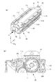
次に、プロセスカートリッジ30を装置本体69に装着する構成及び動作について、図5ないし図9を用いて説明する。プロセスカートリッジ30を装置本体69に装着する際には、図5に示すように、保護カバー10の挿入方向(第1方向)先端に設けた突き当て部(先端部)40を装置本体69の規制部としての挿入位置決め部72に嵌合させることで、挿入位置を決める。突き当て部40は、図6(a)に示すように、保護カバー10の先端にプロセスカートリッジ30と反対側に突出するように形成されている。突き当て部40の先端面46は、第1方向と直交する平坦面としている。また、突き当て部40のプロセスカートリッジ30側の内側部分は、後述するように、プロセスカートリッジ30が装置本体69の装着位置に到達する際にカートリッジ筐体31の被位置決め部50と当接する当接部45としている。
[Attaching the process cartridge to the main unit]
Next, the configuration and operation of mounting the
挿入位置決め部72は、図6(b)に示すように、装置本体69の開口部38の周囲に挿入方向に凹むように形成され、底面を壁部73としている。挿入位置決め部72の側壁は、保護カバー10の突き当て部40の外形に沿った形状とし、突き当て部40の進入を案内して突き当て部40と嵌合するようにしている。壁部73は、プロセスカートリッジ30を第1方向に挿入する際に、保護カバー10の一部である突き当て部40の先端面46と当接して保護カバー10の第1方向への移動を規制する。
As shown in FIG. 6B, the
また、保護カバー10の突き当て部40には目印41が、装置本体69の挿入位置決め部72の近傍には目印75がそれぞれ設けられている。ユーザやサービスマンなどがプロセスカートリッジ30を装置本体69に挿入する際には、図5に示すように、突き当て部40の目印41と装置本体69の目印75とを合わせるように、突き当て部40を挿入位置決め部72に進入させる。そして、位置合わせが行われた状態で、プロセスカートリッジ30の把手42を矢印P方向(挿入方向)に押すことで、突き当て部40の先端面46が、挿入位置決め部72の壁部73に突き当たる。この状態で、プロセスカートリッジ30を装置本体69に挿入する際の位置決めがなされる。
Further, a
この状態から、更にプロセスカートリッジ30を挿入方向に押すことで、保護カバー10が先端面46と壁部73との当接によりそれ以上移動することが阻止され、プロセスカートリッジ30が保護カバー10に対して相対移動を開始する。この際、保護カバー10の係止部43が外れて、プロセスカートリッジ30が保護カバー10を残して装置本体69内に挿入される。このとき、保護カバー10の係合爪11R、11Lとカートリッジ筐体31の係合溝34R、34Lとが複数係合していることで、保護カバー10がプロセスカートリッジ30を、図5のZ軸方向(上下方向)に規制をしつつ、Y軸方向(挿入方向)に案内する。
From this state, by further pushing the
プロセスカートリッジ30が、図7(a)に示すように、装置本体69への装着位置に到達すると、保護カバー10の突き当て部40がカートリッジ筐体31と装置本体69との間で挟持される。ここで、突き当て部40には、図7(b)に示すように、プロセスカートリッジ30が装着位置に到達する際にカートリッジ筐体31の被位置決め部50と当接する当接部45が形成されている。当接部45は、被位置決め部50と同様に樹脂により形成され、被位置決め部50との当接面45aが装置本体69の位置決め部70よりも被位置決め部側に位置する。したがって、この状態では、図7(b)に示すように、被位置決め部50と位置決め部70との間には隙間Gが存在し、被位置決め部50と位置決め部70とが当接することはない。
As shown in FIG. 7A, when the
また、図8に示すように、プロセスカートリッジ30が装着位置に到達する際には、カートリッジ筐体31が付勢部71により付勢力が付与される。即ち、カートリッジ筐体31の下面の挿入方向上流側には、下方に突出するように突出部37が形成されている。突出部37は、下面に当接面37aと当接面37aよりも挿入方向下流に、下流に向かうほど上側に傾斜した傾斜面37bを有する。プロセスカートリッジ30を矢印P方向に挿入すると、装置本体69に設けられた付勢部71の突き当て部71aが傾斜面37bと当接して、付勢部71の圧縮ばね71bが弾性的に圧縮される。更にプロセスカートリッジ30が挿入されることで、図8(b)に示すように、突き当て部71aが突出部37の当接面37aと当接し、突出部37を介してカートリッジ筐体31が付勢部71により上方に付勢される。
Further, as shown in FIG. 8, when the
本実施形態では、プロセスカートリッジ30が装着位置に至る直前に、付勢部71による付勢が開始される。この付勢部71の付勢力は、ユーザなどがプロセスカートリッジ30を装置本体69に挿入する力に対する挿入負荷となるため、付勢力が発生するのは装着位置の直前であることが望ましい。しかしながら、本実施形態では、突出部37の当接面37aと付勢部71の位置のばらつき及びプロセスカートリッジ30の挿入方向の位置を決める装置本体側の挿入位置決め部の位置のばらつきを考慮している。このため、付勢部71からカートリッジ筐体31に付勢力を発生させる位置は、装着位置よりも所定距離手前とした。本実施形態では、付勢部71の突き当て部71が突出部37の傾斜面37bと当接を開始する位置から装着位置までの所定距離は、2mmとした。これは、本実施形態では突出部37と付勢部71との挿入方向の位置のばらつきが所定位置に対して±0.6mmであるため、このばらつきの2倍以上の安全率を確保するためである。
In the present embodiment, urging by the urging
一方、上述したように、保護カバー10の突き当て部40に形成された当接部45がカートリッジ筐体31の被位置決め部50と当接するために、被位置決め部50は、プロセスカートリッジ30の挿入時に当接部45に案内されることになる。このために、保護カバー10は、図9に示すように、当接部45の第1方向上流に被位置決め案内部44を形成している。被位置決め案内部44は、当接部45と同様に樹脂により形成され、上流に向かうほど上側に向かうように傾斜した傾斜面としている。このような被位置決め案内部44は、プロセスカートリッジ30の挿入動作に伴ってカートリッジ筐体31が第1方向に相対移動する際に、被位置決め部50と摺接して被位置決め部50を当接部45に案内する。
On the other hand, as described above, since the abutting
このようにプロセスカートリッジ30が装着位置に到達した状態では、カートリッジ筐体31の被位置決め部50と保護カバー10の突き当て部40に形成された当接部45とが当接する。また、付勢部71によりカートリッジ筐体31が付勢されることで、保護カバー10の先端部としての突き当て部40がカートリッジ筐体31と装置本体69との間で挟持されることで保持される。
Thus, in the state where the
この結果、図7(b)及び図9に示すように、保護カバー10の当接部45が、板金製の位置決め部70と被位置決め部50との間にスペーサとなる。そして、プロセスカートリッジ30が装置本体69の装着位置に到達する際に、位置決め部70と被位置決め部50との間に隙間Gを維持し、位置決め部70と被位置決め部50とが加圧接触しながら擦れることを防いでいる。
As a result, as shown in FIGS. 7B and 9, the
更に、このように装着位置に到達したカートリッジ筐体31から保護カバー10を離脱させることで、被位置決め部50が、付勢部71に付勢されて位置決め部70に当接する。そして、プロセスカートリッジ30の装置本体69に対する上下方向(第2方向)の位置決めがなされ、プロセスカートリッジ30の装置本体69への装着が完了する。
Further, by removing the
ここで、カートリッジ筐体31から離脱する前の保護カバー10突き当て部(先端部)40は、カートリッジ筐体31と装置本体69との間で、付勢部71の付勢力により挟持されることで保持されている。言い換えれば、付勢部71は、プロセスカートリッジ30が装着されたときに、保護カバー10の先端部が装置本体69とプロセスカートリッジ30とによって挟持される付勢力が付与されるようにプロセスカートリッジ30を付勢可能である。このため、保護カバー10は、プロセスカートリッジ30の挿入開始時の姿勢のまま保持される。そして、その保持された保護カバー10をユーザなどが挿入方向と逆方向に引き抜くことで、保護カバー10がカートリッジ筐体31から離脱し、上述のようにプロセスカートリッジ30の装置本体69に対する第2方向の位置決めがなされる。この際、保護カバー10が付勢部71の付勢力により挟持されているだけであるため、保護カバー10のどの部分を持っても容易に外すことが可能である。
Here, the
このように、プロセスカートリッジ30が装着位置に到達する際に、カートリッジ筐体31の被位置決め部50と保護カバー10の当接部45とが当接する。このため、この際に、装置本体69の位置決め部70とカートリッジ筐体31の被位置決め部50とが擦れることを防止できる。また、保護カバー10の当接部45及び被位置決め案内部44は、被位置決め部50と同様に樹脂で形成されており、挿入時に擦れても、被位置決め部50が削れることや、挿入動作の負荷となることが少ない。
Thus, when the
したがって、本実施形態によれば、プロセスカートリッジ30の挿入動作における負荷を低減することが可能であると共に、被位置決め部50の削れによる装置本体69の装着位置のズレも低減可能である。よって、ユーザなどが、プロセスカートリッジ30の設置作業及び交換作業をより容易に行うことができる。
Therefore, according to the present embodiment, it is possible to reduce the load in the insertion operation of the
特に本実施形態の場合、プロセスカートリッジ30が装置本体69に装着されたときに、付勢部71の付勢力により、保護カバー10の先端部が装置本体69とプロセスカートリッジ30とによって挟持される。このため、プロセスカートリッジ30の装着完了に伴い、保護カバー10が装置本体69に対して外れてしまうことを簡易な構成で抑制できる。
Particularly in the case of the present embodiment, when the
[他の実施形態]
なお、上述の説明では、保護カバー10の装置本体69への位置決めは、保護カバー10の挿入方向先端部(突き当て部40)を装置本体69の凹部(挿入位置決め部72)に当てはめる構成とした。但し、例えば、装置本体側の位置決め軸と保護カバー側の穴が係合することで位置決めが成される構成でも構わない。
[Other Embodiments]
In the above description, the
また、上述の説明では、プロセスカートリッジ30の被位置決め部50と当接する保護カバー10の当接部45及び被位置決め案内部44を樹脂で構成している。但し、プロセスカートリッジの挿入動作の負荷が低減することが目的であるため、当接部45及び被位置決め案内部44を、例えば、亜鉛メッキされた鋼板面によって構成しても良い。
In the above description, the
1・・・感光ドラム(像担持体)/2・・・帯電装置(帯電手段)/3・・・現像装置(現像手段)/4・・・クリーナ装置(清掃手段)/10・・・保護カバー(カバー)/11R、11L・・・係合爪(挿入案内部)/30・・・プロセスカートリッジ(カートリッジ)/31・・・カートリッジ筐体/35・・・露出部/38・・・開口部/40・・・突き当て部(先端部)/43・・・係止部/44・・・被位置決め案内部/45・・・当接部/45a・・・当接面/50・・・被位置決め部/69・・・装置本体/70・・・位置決め部/71・・・付勢部/72・・・挿入位置決め部(規制部)/73・・・壁部
DESCRIPTION OF
Claims (8)
前記装置本体に設けられ、前記カートリッジを第1方向から挿入自在な開口部と、
前記カートリッジを装置本体に挿入する際に、前記カバーの先端部と嵌合して、前記カバーの前記第1方向への移動を規制する規制部と、
前記カートリッジが装着されたときに、前記カバーの前記先端部が前記装置本体と前記カートリッジとによって挟持される付勢力が付与されるように前記カートリッジを付勢可能な付勢部と、を有する、
ことを特徴とする画像形成装置。 At least an image carrier, and a cartridge housing that holds the image carrier and has an exposed portion from which a part of the surface of the image carrier is exposed . In a state, a cartridge that is detachably attached to the cartridge housing and is attached to the cartridge housing to cover the exposed portion ;
Said device provided on the main body, freely inserting said cartridge from a first direction opening,
When inserting the cartridge into the apparatus main body, a restricting portion that fits with the tip of the cover and restricts the movement of the cover in the first direction;
A biasing portion capable of biasing the cartridge such that when the cartridge is mounted, a biasing force is applied to the front end portion of the cover by the device main body and the cartridge;
An image forming apparatus.
前記カートリッジに設けられ、前記カートリッジが装着位置にあるときに前記位置決め部と当接可能な被位置決め部と、を備え、
前記付勢部は、前記カバーが本体から取り外された場合に、前記被位置決め部を位置決め部に当接させる、
ことを特徴とする請求項1に記載の画像形成装置。 A positioning portion for positioning in a second direction intersecting the first direction of the cartridge;
A positioned portion provided on the cartridge and capable of contacting the positioning portion when the cartridge is in the mounting position;
The urging portion causes the positioning portion to contact the positioning portion when the cover is removed from the main body.
The image forming apparatus according to claim 1.
ことを特徴とする請求項2に記載の画像形成装置。 The portion to be positioned, when said cartridge reaches said mounting position, the contact portion and the contact of the cover abutment surface is positioned at the portion to be positioned side of the positioning portion of the portion to be positioned ,
The image forming apparatus according to claim 2.
ことを特徴とする、請求項3に記載の画像形成装置。 The positioned portion slides with a positioned guide portion formed upstream of the contact portion in the first direction when the cartridge housing moves relative to the first direction in accordance with the insertion operation of the cartridge. In contact with and guided by the contact portion,
The image forming apparatus according to claim 3, wherein:
ことを特徴とする、請求項1ないし4のうちの何れか1項に記載の画像形成装置。 The cartridge housing is guided in the first direction by an insertion guide portion of the cover in accordance with an insertion operation of the cartridge.
The image forming apparatus according to claim 1 , wherein the image forming apparatus is an image forming apparatus.
ことを特徴とする、請求項1ないし5のうちの何れか1項に記載の画像形成装置。 The cartridge housing is locked when the cover is locked, and the locking portion of the cartridge is locked when the cartridge housing moves relative to the cover in the first direction. Is formed to come off,
The image forming apparatus according to claim 1, wherein the image forming apparatus is an image forming apparatus.
ことを特徴とする、請求項1ないし6のうちの何れか1項に記載の画像形成装置。 The cartridge includes the image carrier, a charging unit that charges the surface of the image carrier, and a cleaning unit that cleans the surface of the image carrier.
The image forming apparatus according to claim 1, wherein the image forming apparatus is an image forming apparatus.
ことを特徴とする、請求項7に記載の画像形成装置。 The cartridge includes developing means for developing an electrostatic latent image formed on the surface of the image carrier.
The image forming apparatus according to claim 7, wherein:
Priority Applications (2)
| Application Number | Priority Date | Filing Date | Title |
|---|---|---|---|
| JP2013224892A JP6192486B2 (en) | 2013-10-30 | 2013-10-30 | Image forming apparatus |
| US14/524,929 US9348305B2 (en) | 2013-10-30 | 2014-10-27 | Image forming apparatus with a cartridge that includes and image bearing member |
Applications Claiming Priority (1)
| Application Number | Priority Date | Filing Date | Title |
|---|---|---|---|
| JP2013224892A JP6192486B2 (en) | 2013-10-30 | 2013-10-30 | Image forming apparatus |
Publications (3)
| Publication Number | Publication Date |
|---|---|
| JP2015087490A JP2015087490A (en) | 2015-05-07 |
| JP2015087490A5 JP2015087490A5 (en) | 2016-12-15 |
| JP6192486B2 true JP6192486B2 (en) | 2017-09-06 |
Family
ID=52995631
Family Applications (1)
| Application Number | Title | Priority Date | Filing Date |
|---|---|---|---|
| JP2013224892A Active JP6192486B2 (en) | 2013-10-30 | 2013-10-30 | Image forming apparatus |
Country Status (2)
| Country | Link |
|---|---|
| US (1) | US9348305B2 (en) |
| JP (1) | JP6192486B2 (en) |
Cited By (1)
| Publication number | Priority date | Publication date | Assignee | Title |
|---|---|---|---|---|
| US11675307B2 (en) | 2021-06-08 | 2023-06-13 | Canon Kabushiki Kaisha | Image forming apparatus |
Families Citing this family (4)
| Publication number | Priority date | Publication date | Assignee | Title |
|---|---|---|---|---|
| WO2016009867A1 (en) * | 2014-07-15 | 2016-01-21 | 京セラドキュメントソリューションズ株式会社 | Image forming device |
| JP6358195B2 (en) * | 2015-08-28 | 2018-07-18 | 京セラドキュメントソリューションズ株式会社 | Image forming apparatus |
| JP2022056493A (en) * | 2020-09-30 | 2022-04-11 | 富士フイルムビジネスイノベーション株式会社 | Protective member, replacement member with protective member, and image forming apparatus |
| JP2023043462A (en) * | 2021-09-16 | 2023-03-29 | キヤノン株式会社 | Cartridge protection assembly |
Family Cites Families (9)
| Publication number | Priority date | Publication date | Assignee | Title |
|---|---|---|---|---|
| US4655578A (en) * | 1986-03-24 | 1987-04-07 | Xerox Corporation | Reproducing apparatus cartridge mounting assembly |
| JPH06250481A (en) * | 1993-02-24 | 1994-09-09 | Canon Inc | Image forming device |
| JP3507227B2 (en) * | 1995-10-26 | 2004-03-15 | キヤノン株式会社 | Process cartridge and electrophotographic image forming apparatus |
| JP4107574B2 (en) * | 2002-10-03 | 2008-06-25 | 株式会社リコー | Image forming apparatus, process cartridge, and cover member |
| JP4983050B2 (en) * | 2006-03-06 | 2012-07-25 | 富士ゼロックス株式会社 | Protective cover, process cartridge using the same, image forming apparatus, and process cartridge mounting method |
| JP5388442B2 (en) * | 2006-12-11 | 2014-01-15 | キヤノン株式会社 | Process cartridge and electrophotographic image forming apparatus |
| US7929881B2 (en) * | 2006-12-11 | 2011-04-19 | Canon Kabushiki Kaisha | Process cartridge and electrophotographic image forming apparatus |
| JP4630932B2 (en) * | 2008-05-27 | 2011-02-09 | キヤノン株式会社 | Process cartridge and image forming apparatus |
| JP5393642B2 (en) * | 2010-11-30 | 2014-01-22 | 京セラドキュメントソリューションズ株式会社 | Photosensitive unit and image forming apparatus |
-
2013
- 2013-10-30 JP JP2013224892A patent/JP6192486B2/en active Active
-
2014
- 2014-10-27 US US14/524,929 patent/US9348305B2/en active Active
Cited By (1)
| Publication number | Priority date | Publication date | Assignee | Title |
|---|---|---|---|---|
| US11675307B2 (en) | 2021-06-08 | 2023-06-13 | Canon Kabushiki Kaisha | Image forming apparatus |
Also Published As
| Publication number | Publication date |
|---|---|
| US20150117902A1 (en) | 2015-04-30 |
| JP2015087490A (en) | 2015-05-07 |
| US9348305B2 (en) | 2016-05-24 |
Similar Documents
| Publication | Publication Date | Title |
|---|---|---|
| JP6140963B2 (en) | Cartridge and image forming apparatus | |
| JP4945261B2 (en) | Image forming apparatus | |
| US8768208B2 (en) | Image forming apparatus with cartridge supporting member and preventing members for ensuring mounting of cartridges in associated mounting portions | |
| JP6192486B2 (en) | Image forming apparatus | |
| JP4384251B1 (en) | Developing cartridge, process cartridge, and electrophotographic image forming apparatus | |
| US20170261917A1 (en) | Developing cartridge | |
| US8180251B2 (en) | Cover and cartridge | |
| JP2007322554A (en) | Photoreceptor unit and image forming apparatus | |
| JP2011180268A (en) | Image forming apparatus | |
| JP2008158381A (en) | Image forming apparatus | |
| CN106814564B (en) | Charging device and image forming apparatus | |
| JP5062233B2 (en) | Process cartridge | |
| US10018961B2 (en) | Image forming apparatus having a rotatable development carrying member disposed in a particular relation to a developer supply roller | |
| JP6361608B2 (en) | Image forming apparatus | |
| JP2009271276A (en) | Waste toner recovering device and image forming apparatus using the same | |
| JP6493310B2 (en) | Image forming apparatus | |
| JP5866885B2 (en) | Photosensitive unit and image forming apparatus | |
| JP2018072542A (en) | Image formation apparatus | |
| JP7494499B2 (en) | Image forming device | |
| JP4995243B2 (en) | Developing cartridge, process cartridge, and electrophotographic image forming apparatus | |
| JP2013156503A (en) | Developing device, process cartridge, and image forming apparatus | |
| JP4978029B2 (en) | Image forming apparatus | |
| JP2009271266A (en) | Image forming apparatus | |
| JP5007699B2 (en) | Image forming apparatus | |
| JP2019109283A (en) | Image forming apparatus |
Legal Events
| Date | Code | Title | Description |
|---|---|---|---|
| A521 | Written amendment |
Free format text: JAPANESE INTERMEDIATE CODE: A523 Effective date: 20161027 |
|
| A621 | Written request for application examination |
Free format text: JAPANESE INTERMEDIATE CODE: A621 Effective date: 20161027 |
|
| A977 | Report on retrieval |
Free format text: JAPANESE INTERMEDIATE CODE: A971007 Effective date: 20170628 |
|
| TRDD | Decision of grant or rejection written | ||
| A01 | Written decision to grant a patent or to grant a registration (utility model) |
Free format text: JAPANESE INTERMEDIATE CODE: A01 Effective date: 20170711 |
|
| A61 | First payment of annual fees (during grant procedure) |
Free format text: JAPANESE INTERMEDIATE CODE: A61 Effective date: 20170808 |
|
| R151 | Written notification of patent or utility model registration |
Ref document number: 6192486 Country of ref document: JP Free format text: JAPANESE INTERMEDIATE CODE: R151 |