JP6192169B2 - Cooker - Google Patents

Cooker Download PDF

Info

Publication number
JP6192169B2
JP6192169B2 JP2014083030A JP2014083030A JP6192169B2 JP 6192169 B2 JP6192169 B2 JP 6192169B2 JP 2014083030 A JP2014083030 A JP 2014083030A JP 2014083030 A JP2014083030 A JP 2014083030A JP 6192169 B2 JP6192169 B2 JP 6192169B2
Authority
JP
Japan
Prior art keywords
container
yeast
ingredient
support surface
bread
Prior art date
Legal status (The legal status is an assumption and is not a legal conclusion. Google has not performed a legal analysis and makes no representation as to the accuracy of the status listed.)
Active
Application number
JP2014083030A
Other languages
Japanese (ja)
Other versions
JP2015202202A5 (en
JP2015202202A (en
Inventor
賢治 森田
賢治 森田
山下 太一郎
太一郎 山下
武史 坂口
武史 坂口
和春 石田
和春 石田
Current Assignee (The listed assignees may be inaccurate. Google has not performed a legal analysis and makes no representation or warranty as to the accuracy of the list.)
Hitachi Appliances Inc
Original Assignee
Hitachi Appliances Inc
Priority date (The priority date is an assumption and is not a legal conclusion. Google has not performed a legal analysis and makes no representation as to the accuracy of the date listed.)
Filing date
Publication date
Application filed by Hitachi Appliances Inc filed Critical Hitachi Appliances Inc
Priority to JP2014083030A priority Critical patent/JP6192169B2/en
Priority to TW103137019A priority patent/TWI591297B/en
Publication of JP2015202202A publication Critical patent/JP2015202202A/en
Publication of JP2015202202A5 publication Critical patent/JP2015202202A5/ja
Application granted granted Critical
Publication of JP6192169B2 publication Critical patent/JP6192169B2/en
Active legal-status Critical Current
Anticipated expiration legal-status Critical

Links

Images

Landscapes

  • Baking, Grill, Roasting (AREA)

Description

本発明は、加熱調理器に関する。   The present invention relates to a cooking device.

特許文献1には、自動的にパンを焼成できるベーカリー機能を有する加熱調理器が記載されている。この加熱調理器は、パン生地に顆粒のドライイーストを自動的に投入可能になっている。段落0065には、「第一の具材底板67が、第一の具材投入手段43の円形開口の下方に移動し、開放された円形開口から、ドライイースト133がパン焼成容器28に投入される。」と記載されている。   Patent Document 1 describes a cooking device having a bakery function capable of automatically baking bread. This cooking device can automatically add granular dry yeast to bread dough. In the paragraph 0065, “The first ingredient bottom plate 67 moves below the circular opening of the first ingredient charging means 43, and the dry yeast 133 is introduced into the bread baking container 28 from the opened circular opening. Is described.

特開2014−042770号公報JP 2014-042770 A

特許文献1に記載される加熱調理器は、すり鉢状を呈する第一の具材投入手段で顆粒のドライイーストを保持する。第一の具材投入手段は、底部が開閉可能となっている。そして、底部が開放されたときに、第一の具材投入手段に保持されているドライイーストがパン焼成容器に落下投入される。
特許文献1に記載される加熱調理器は、第一の具材投入手段の底部に形成される円形開口からドライイーストを落下させる。
The heating cooker described in Patent Document 1 holds granular dry yeast by a first ingredient charging means having a mortar shape. As for the 1st material injection | throwing-in means, the bottom part can be opened and closed. Then, when the bottom is opened, the dry yeast held in the first ingredient charging means is dropped into the bread baking container.
The heating cooker described in patent document 1 drops dry yeast from the circular opening formed in the bottom part of a 1st material injection | throwing-in means.

特許文献1の加熱調理器は、パンの焼成時にパン生地やドライイースト等の具材がセットされた後で所定時間の経過後に焼成を開始し、利用者が所望する時刻にパンが焼き上がるタイマー予約が可能になっている。パンの焼成がタイマー予約されると、ドライイーストは長時間に亘って第一の具材投入手段に保持される場合がある。
第一の具材投入手段は、円形開口が閉じられた状態であっても、顆粒のドライイーストは落下しないが空気が流通する程度の隙間が円形開口の外周に生じている。
高湿な環境でパンの焼成がタイマー予約されると、高湿な空気が円形開口の外周に生じる隙間を通って第一の具材投入手段に入り込みドライイーストが徐々に吸湿する。そして、ドライイーストは、パン焼成容器に落下投入される前に吸湿して大きな塊状になることがある。
The heating cooker of Patent Document 1 starts timer baking after a predetermined time has elapsed after ingredients such as bread dough and dry yeast are set at the time of baking bread, and timer reservation is performed so that bread is baked at the time desired by the user Is possible. When the baking of the bread is reserved as a timer, the dry yeast may be held in the first ingredient input means for a long time.
Even if the first material charging means is in a state where the circular opening is closed, the dry yeast of the granule does not fall, but a gap that allows air to flow is formed on the outer periphery of the circular opening.
When a timer is reserved for baking bread in a high humidity environment, high humidity air enters the first ingredient charging means through a gap formed on the outer periphery of the circular opening, and the dry yeast gradually absorbs moisture. The dry yeast may absorb moisture before being dropped into the bread baking container and become a large lump.

そこで、本発明は、具材容器が保持する具材を残留なく加熱容器に落下投入できる調理手段を備える加熱調理器を提供することを課題とする。   Then, this invention makes it a subject to provide a heating cooker provided with the cooking means which can drop-inject into the heating container the ingredients which an ingredient container hold | maintains without remaining.

前記課題を解決するため、本発明は、加熱する材料が入れられる加熱容器と、前記加熱容器の上方に取り付けられる具材容器と、を有する調理手段が加熱室に装着され、前記具材容器は、保持している具材を前記加熱容器に落下投入する具材投入手段を有し、前記具材投入手段は開口部が上方を向いた正立状態で前記具材を保持する保持容器と、前記保持容器を前記正立状態で下方から支持する支持面部と、前記支持面部を第1の回動軸周りに回動させて前記保持容器から離反させる回動機構と、を有し、前記保持容器は、前記支持面部が離反したときに前記正立状態から第2の回動軸周りに回動して傾倒することで前記具材を前記加熱容器に落下投入するように構成した特徴を有する。 In order to solve the above-mentioned problem, the present invention is provided with cooking means having a heating container in which a material to be heated is placed and an ingredient container attached above the heating container, and the ingredient container is attached to the heating chamber. the Guzai holding have ingredients dosing means falling charged into the heating vessel, the ingredient supplying device includes: a holding vessel for holding said ingredient in an erected state in which the opening facing upward A support surface portion that supports the holding container from below in the upright state, and a rotation mechanism that rotates the support surface portion around a first rotation axis to separate the holding container from the holding container, holding container, characterized said support surface is configured to drop-on the ingredient into the heating container by tilting from the erecting state when separated by rotating the second rotational shaft around Have.

本発明によると、具材容器が保持する具材を残留なく加熱容器に落下投入でき、全てのドライイーストをパン生地の表面全体に落下投入できる調理手段を備える加熱調理器を提供できる。   ADVANTAGE OF THE INVENTION According to this invention, the cooking device provided with the cooking means which can drop-inject the ingredients which an ingredient container hold | maintains into a heating container without residue and can drop-inject all the dry yeast to the whole surface of bread dough can be provided.

ベーカリー手段が装着されている加熱調理器の斜視図である。It is a perspective view of the heating cooker with which the bakery means is mounted | worn. ベーカリー手段が装着されていない加熱調理器の斜視図である。It is a perspective view of the cooking-by-heating machine by which bakery means is not equipped. ベーカリー手段を示す斜視図である。It is a perspective view which shows a bakery means. 具材容器の斜視図である。It is a perspective view of an ingredient container. 具材容器の下方を示す斜視図である。It is a perspective view which shows the downward direction of an ingredient container. (a)は図4におけるSec1−Sec1での断面図、(b)はイースト容器の斜視図である。(A) is sectional drawing in Sec1-Sec1 in FIG. 4, (b) is a perspective view of a yeast container. 図4におけるSec2−Sec2での断面図である。It is sectional drawing in Sec2-Sec2 in FIG. 傾倒規制板の斜視図である。It is a perspective view of a tilt control board. イースト容器が傾倒規制板に載置された状態を示す斜視図である。It is a perspective view which shows the state in which the yeast container was mounted in the inclination control board. (a)は図4におけるSec3−Sec3での断面図、(b)はイースト容器が傾倒した状態を示す図である。(A) is sectional drawing in Sec3-Sec3 in FIG. 4, (b) is a figure which shows the state which the yeast container inclined. イースト投入レバーの斜視図である。It is a perspective view of a yeast throwing lever. (a)はイースト容器が傾倒していない状態の具材容器の下方を示す斜視図、(b)はイースト容器が傾倒した状態の具材容器の下方を示す斜視図である。(A) is a perspective view which shows the downward direction of the ingredient container in the state where the yeast container is not tilted, (b) is a perspective view which shows the downward direction of the ingredient container in the state where the yeast container is tilted. 第一の具材投入手段及び第二の具材投入手段を操作する具材投入操作機構の斜視図である。It is a perspective view of the material input operation mechanism which operates a 1st material input means and a 2nd material input means. 押圧突起の機能を説明する図である。It is a figure explaining the function of a press protrusion.

以下、適宜図を参照して本発明の実施例を詳細に説明する。   Hereinafter, embodiments of the present invention will be described in detail with reference to the drawings as appropriate.

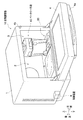
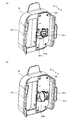
図1はベーカリー手段が装着されている加熱調理器の斜視図である。図2はベーカリー手段が装着されていない加熱調理器の斜視図である。
なお、本実施例に係る加熱調理器10の基本的な構造は、前記した特許文献1に記載される加熱調理器と同等である。
FIG. 1 is a perspective view of a cooking device equipped with bakery means. FIG. 2 is a perspective view of a cooking device without a bakery means.
In addition, the basic structure of the heating cooker 10 which concerns on a present Example is equivalent to the heating cooker described in patent document 1 mentioned above.

図1に示すように、加熱調理器10の本体1には、加熱室2の前面に前面開口3が設けられている。前面開口3は開閉扉4で開閉される。開閉扉4の上部には把手4aが設けられている。本体1の前面には、開閉扉4の開閉状態を検知する扉スイッチ4bが設けられている。加熱調理器10は、この扉スイッチ4bにより、開閉扉4が開いている状態で電源が投入されないように構成されている。本実施例の加熱調理器10は、制御装置6で制御される。
加熱室2の内部には、調理手段としてのベーカリー手段40が装着ガイド30を介して着脱自在に装着される。ベーカリー手段40は、パンを焼成する際に使用される。なお、図1には、開閉扉4の回転支点が前面開口3の下方にある例を示したが、開閉扉4の回転支点が前面開口3の側方(左方又は右方)にある構成としてもよい。
なお、本実施例の加熱調理器10は、前方(開閉扉4が備わる側)からみて左右が設定される。
As shown in FIG. 1, a main body 1 of a heating cooker 10 is provided with a front opening 3 on the front surface of a heating chamber 2. The front opening 3 is opened and closed by an opening / closing door 4. A handle 4 a is provided at the top of the open / close door 4. On the front surface of the main body 1, a door switch 4b for detecting the open / close state of the open / close door 4 is provided. The cooking device 10 is configured such that the door switch 4b prevents the power from being turned on when the door 4 is open. The heating cooker 10 of this embodiment is controlled by the control device 6.
A bakery means 40 as a cooking means is detachably mounted inside the heating chamber 2 via a mounting guide 30. The bakery means 40 is used when baking bread. 1 shows an example in which the rotation fulcrum of the open / close door 4 is below the front opening 3. However, the rotation fulcrum of the open / close door 4 is on the side (left or right) of the front opening 3. It is good.
In addition, as for the heating cooker 10 of a present Example, right and left are set seeing from the front (side with the opening-and-closing door 4).

図2に示すように、加熱室2の底面2aには、前側左右の2ヶ所と後方中央1ヶ所の計3ヶ所に重量センサ2bが設けられている。これらの重量センサ2bには、テーブルプレート5(図2では点線で示す)が着脱自在に載置される。テーブルプレート5は、セラミックのような低損失の誘電体素材で構成される。マイクロ波加熱を行う際には、重量センサ2bにテーブルプレート5が載置される。加熱調理器10の制御装置6は、テーブルプレート5上に載置された食品の質量を測定してマイクロ波加熱の熱量または加熱時間を制御する。一方、パンの焼成時には、図1に示すようにベーカリー手段40が装着される。   As shown in FIG. 2, weight sensors 2b are provided on the bottom surface 2a of the heating chamber 2 at a total of three locations, two on the front left and right and one on the rear center. A table plate 5 (shown by a dotted line in FIG. 2) is detachably mounted on these weight sensors 2b. The table plate 5 is made of a low-loss dielectric material such as ceramic. When performing microwave heating, the table plate 5 is placed on the weight sensor 2b. The control device 6 of the heating cooker 10 measures the mass of food placed on the table plate 5 and controls the heat amount or heating time of microwave heating. On the other hand, when baking bread, bakery means 40 is mounted as shown in FIG.

ベーカリー手段40(図1参照)は、図2に示す装着ガイド30を介して加熱室2の底面2aに装着される。装着ガイド30は略扁平状を呈し、駆動軸孔31と、ガイド底面32a及びガイド側壁32bと、を備える。ガイド側壁32bはガイド底面32aの両側(左右両側)に形成されている。
駆動軸孔31は、上下に貫通する円形状の孔であり、ベーカリー手段40の下部に設けられた攪拌駆動軸16が挿通する。攪拌駆動軸16は図示しないモータが出力する回転駆動力で回転する。
The bakery means 40 (see FIG. 1) is mounted on the bottom surface 2a of the heating chamber 2 via the mounting guide 30 shown in FIG. The mounting guide 30 has a substantially flat shape, and includes a drive shaft hole 31, a guide bottom surface 32a, and guide side walls 32b. The guide side walls 32b are formed on both sides (left and right sides) of the guide bottom surface 32a.
The drive shaft hole 31 is a circular hole penetrating vertically, and the stirring drive shaft 16 provided at the lower portion of the bakery means 40 is inserted therethrough. The agitation drive shaft 16 rotates with a rotational driving force output from a motor (not shown).

装着ガイド30は、加熱室2の側壁(例えば、右方の側壁)に沿って底面2aに載置される。このとき、攪拌駆動軸16が駆動軸孔31を挿通する。
ベーカリー手段40は、ガイド底面32aに載置されてガイド側壁32bにガイドされて装着ガイド30に取り付けられる。装着ガイド30の駆動軸孔31を挿通する攪拌駆動軸16は、ベーカリー手段40の駆動連結部43(図3参照)に接続される。
The mounting guide 30 is placed on the bottom surface 2 a along the side wall (for example, the right side wall) of the heating chamber 2. At this time, the stirring drive shaft 16 passes through the drive shaft hole 31.
The bakery means 40 is mounted on the mounting guide 30 by being placed on the guide bottom surface 32 a and guided by the guide side wall 32 b. The stirring drive shaft 16 inserted through the drive shaft hole 31 of the mounting guide 30 is connected to the drive connecting portion 43 (see FIG. 3) of the bakery means 40.

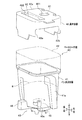
図3はベーカリー手段を示す斜視図である。
図3に示すように、ベーカリー手段40は、加熱容器(パン焼成容器41)と具材容器42とからなる。パン焼成容器41はカップ状を呈し、加熱する材料(パン生地B)が内側に入れられる。パン焼成容器41の底部には駆動連結部43が設けられている。パン焼成容器41の前部には取手41aが設けられている。なお、ベーカリー手段40は、図1に示す加熱室2に装着されたときに開閉扉4の方向となる側を前部とする。
具材容器42はパン焼成容器41の上端(開口部が形成される端部)に載置され、パン焼成容器41に落下投入される具材を保持する。
FIG. 3 is a perspective view showing the bakery means.
As shown in FIG. 3, the bakery means 40 includes a heating container (bread baking container 41) and an ingredient container 42. The bread baking container 41 has a cup shape, and a material to be heated (bread dough B) is placed inside. A drive connecting portion 43 is provided at the bottom of the bread baking container 41. A handle 41 a is provided at the front of the bread baking container 41. In addition, the bakery means 40 makes the front side the direction which is the direction of the door 4 when it is mounted in the heating chamber 2 shown in FIG.
The ingredient container 42 is placed on the upper end (the end where the opening is formed) of the bread baking container 41, and holds the ingredients dropped into the bread baking container 41.

具材容器42は、上方となる天面部42aの左右に係合面42bが垂れ下がった略鞍型を呈する。具材容器42は左右の係合面42bがパン焼成容器41の側面に係合して取り付けられる。天面部42aは、パン焼成容器41の開口部にまたがって配置される。
また、装着ガイド30のガイド底面32a(図2参照)には、パン焼成容器41の底部が載置される。そして、駆動連結部43は駆動軸孔31と同じ位置になる。
The material container 42 has a substantially bowl shape in which the engagement surfaces 42b hang down on the left and right of the top surface portion 42a. The ingredient container 42 is attached with the left and right engaging surfaces 42 b engaged with the side surfaces of the bread baking container 41. The top surface part 42 a is disposed across the opening of the bread baking container 41.
Further, the bottom of the bread baking container 41 is placed on the guide bottom surface 32a (see FIG. 2) of the mounting guide 30. The drive connecting portion 43 is in the same position as the drive shaft hole 31.

駆動連結部43には、攪拌羽根45をパン焼成容器41の内側底部に取り付ける回転軸45aが回転自在に備わる。回転軸45aは、ベーカリー手段40が加熱室2(図1参照)に装着されたときに、装着ガイド30の駆動軸孔31を挿通する攪拌駆動軸16(図2参照)と接続される。攪拌駆動軸16が回転すると回転軸45aに取り付けられた攪拌羽根45が回転し、ベーカリー手段40に入れられたパン生地Bが攪拌される。
なお、符号48は、パン焼成容器41を装着ガイド30に固定するためのロックレバーである。装着ガイド30を加熱室2に装着する構造、ベーカリー手段40を装着ガイド30に装着する構造は、前記した特許文献1に記載される構造を適用可能である。
The drive connecting portion 43 is rotatably provided with a rotating shaft 45 a for attaching the stirring blade 45 to the inner bottom portion of the bread baking container 41. The rotating shaft 45a is connected to the stirring drive shaft 16 (see FIG. 2) that passes through the drive shaft hole 31 of the mounting guide 30 when the bakery means 40 is mounted in the heating chamber 2 (see FIG. 1). When the stirring drive shaft 16 rotates, the stirring blade 45 attached to the rotating shaft 45a rotates, and the bread dough B put in the bakery means 40 is stirred.
Reference numeral 48 denotes a lock lever for fixing the bread baking container 41 to the mounting guide 30. The structure described in Patent Document 1 can be applied to the structure for mounting the mounting guide 30 in the heating chamber 2 and the structure for mounting the bakery means 40 to the mounting guide 30.

本実施例の加熱調理器10(図1参照)は、パン生地Bを練る(攪拌する)練り工程と、練り上がったパン生地Bを発酵させる発酵工程と、発酵したパン生地Bを焼き上げる焼き上げ工程と、を実行してパンを焼成する。練り工程と、発酵工程と、焼き上げ工程と、は制御装置6(図1参照)によって自動的に実行される。   The cooking device 10 (see FIG. 1) of the present embodiment includes a kneading process (stirring) the bread dough B, a fermentation process for fermenting the kneaded bread dough B, and a baking process for baking the fermented bread dough B. Run and bake bread. The kneading process, the fermentation process, and the baking process are automatically executed by the control device 6 (see FIG. 1).

具材容器42は、具材投入手段(第一の具材投入手段421,第二の具材投入手段422)を備えている。第一の具材投入手段421は具材を保持する。本実施例においては、パン生地Bを発酵させる酵母である粉体あるいは顆粒のドライイーストA1等が、第一の具材投入手段421で保持される具材となる。第二の具材投入手段422は、レーズンやナッツなど、パン生地Bに混ぜ込む食材A2を保持する。
第一の具材投入手段421に保持されるドライイーストA1や、第二の具材投入手段422に保持される食材A2は練り工程でパン生地Bに混ぜ込まれる。練り工程では、ドライイーストA1が食材A2よりも先にパン生地Bに混ぜ込まれることが多い。
The material container 42 includes material input means (first material input means 421, second material input means 422). The first material input means 421 holds the material. In the present embodiment, powdery or granulated dry yeast A1, which is yeast that ferments bread dough B, is an ingredient held by the first ingredient input means 421. The second ingredient throwing means 422 holds the ingredients A2 to be mixed into the bread dough B such as raisins and nuts.
The dry yeast A1 held by the first ingredient input means 421 and the food A2 held by the second ingredient input means 422 are mixed into the bread dough B in the kneading process. In the kneading process, the dry yeast A1 is often mixed into the bread dough B before the food A2.

図4は具材容器の斜視図である。図5は具材容器の下方を示す斜視図である。図6の(a)は図4におけるSec1−Sec1での断面図、(b)はイースト容器の斜視図である。   FIG. 4 is a perspective view of the ingredient container. FIG. 5 is a perspective view showing the lower part of the ingredient container. 6A is a cross-sectional view taken along Sec1-Sec1 in FIG. 4, and FIG. 6B is a perspective view of the yeast container.

図4に示すように、具材容器42の天面部42aには、第一の具材投入手段421と、第二の具材投入手段422と、が備わっている。
第二の具材投入手段422は、上方から下方に向かって天面部42aを貫通する空間領域である。第二の具材投入手段422には、上方から第二具材容器440が嵌合する。
第二具材容器440は、内側に保持されたレーズンやナッツ等の食材A2をパン焼成容器41に落下投入するように構成されている。
As shown in FIG. 4, the top surface portion 42 a of the ingredient container 42 includes a first ingredient throwing means 421 and a second ingredient throwing means 422.
The 2nd material injection | throwing-in means 422 is a space area | region which penetrates the top | upper surface part 42a toward the downward direction from upper direction. The second material container 440 is fitted to the second material input means 422 from above.
The second ingredient container 440 is configured so that the food A2 such as raisins and nuts held inside is dropped into the bread baking container 41.

第一の具材投入手段421は、すり鉢状の保持容器(イースト容器421a)を有する。イースト容器421aは、天面部42aの下方に配置される。イースト容器421aは、開口部が天面部42aの側(上方)を向いて配置される。天面部42aはイースト容器421aの位置が開口している。   The first ingredient charging means 421 has a mortar-shaped holding container (yeast container 421a). The yeast container 421a is disposed below the top surface portion 42a. The yeast container 421a is disposed with the opening facing the top surface 42a (upward). The position of the yeast container 421a is opened in the top surface part 42a.

図1に示すように、ベーカリー手段40は、加熱室2において一方(例えば、右方)の側壁に沿って装着される。このとき、第一の具材投入手段421が第二の具材投入手段422よりも側壁の側に配置されるように具材容器42が構成される。図4には、第二の具材投入手段422の右側に第一の具材投入手段421が備わる構造が図示されている。   As shown in FIG. 1, the bakery means 40 is mounted along one (for example, the right) side wall in the heating chamber 2. At this time, the ingredient container 42 is configured such that the first ingredient throwing means 421 is disposed closer to the side wall than the second ingredient throwing means 422. FIG. 4 shows a structure in which the first material input means 421 is provided on the right side of the second material input means 422.

また、図4に示すように、天面部42aにおいて第一の具材投入手段421が配置される側の端部には、2つの切り欠き部(第一切欠部423a,第二切欠部423b)が形成されている。第一切欠部423a及び第二切欠部423bは、天面部42aを貫通している。   Further, as shown in FIG. 4, two notches (first notch 423 a, second notch 423 b) are provided at the end of the top surface portion 42 a on the side where the first material input means 421 is disposed. ) Is formed. The first notch part 423a and the second notch part 423b penetrate the top surface part 42a.

図5に示すように、第一の具材投入手段421と第二の具材投入手段422の間は主隔壁42c1で区画される。また、第一の具材投入手段421は、4つの副隔壁42c2で5つの領域に区画される。
イースト容器421a(図4参照)は、2つの副隔壁42c2で区画されて前後方向の中央に形成される主室425aに配置される。また、第一切欠部423a及び第二切欠部423bは、主室425aに併設されて2つの副隔壁42c2で区画される2つの副室425bのそれぞれに形成されている。
As shown in FIG. 5, the space between the first material input means 421 and the second material input means 422 is partitioned by a main partition wall 42c1. Moreover, the 1st material injection | throwing-in means 421 is divided into five area | regions by the four subpartitions 42c2.
The yeast container 421a (see FIG. 4) is disposed in a main chamber 425a that is partitioned by two sub-partitions 42c2 and formed at the center in the front-rear direction. In addition, the first notch 423a and the second notch 423b are formed in each of the two sub chambers 425b that are provided side by side with the main chamber 425a and partitioned by the two sub partitions 42c2.

なお、第一の具材投入手段421(主室425a,副室425b)は、下方から固定される底板426で閉塞される。第一の具材投入手段421には、ねじ孔が形成されているスタッド42dが備わる。底板426は、スタッド42dにねじ込まれるねじ部材SCで取り付けられる。
底板426には、落下孔426aが開口している。落下孔426aは、イースト容器421a(図4参照)が配置される位置に開口している。主隔壁42c1には切欠溝42c3が形成されている。
In addition, the 1st material injection | throwing-in means 421 (main chamber 425a, subchamber 425b) is obstruct | occluded with the baseplate 426 fixed from the downward direction. The first material input means 421 is provided with a stud 42d in which a screw hole is formed. The bottom plate 426 is attached by a screw member SC that is screwed into the stud 42d.
The bottom plate 426 has a drop hole 426a. The drop hole 426a opens at a position where the yeast container 421a (see FIG. 4) is arranged. A cutout groove 42c3 is formed in the main partition wall 42c1.

図6の(a)に示すように、第一の具材投入手段421に備わるイースト容器421aは、第2の回動軸(容器回動軸421b)で回動自在に軸支される。容器回動軸421bは、イースト容器421aに対して第二の具材投入手段422と逆側(主隔壁42c1と逆側)に配設される。イースト容器421aは容器回動軸421bよりも主隔壁42c1の側に張り出し、自重で容器回動軸421b周りを回動するように構成されている。容器回動軸421bは2つの副隔壁42c2で支持される。   As shown to (a) of FIG. 6, the yeast container 421a with which the 1st material injection | throwing-in means 421 is equipped is rotatably supported by the 2nd rotating shaft (container rotating shaft 421b). The container rotation shaft 421b is disposed on the opposite side of the yeast container 421a from the second material input means 422 (on the opposite side to the main partition wall 42c1). The yeast container 421a is configured to protrude from the container rotation shaft 421b toward the main partition wall 42c1 and rotate around the container rotation shaft 421b by its own weight. The container rotation shaft 421b is supported by two sub-partition walls 42c2.

イースト容器421aの下方には傾倒規制板421cが備わる。傾倒規制板421cは、第1の回動軸(支持面回動軸421d)で回動自在に軸支される。傾倒規制板421cはイースト容器421aの下方に張り出してイースト容器421aの底部を下方から支持する。支持面回動軸421dは2つの副隔壁42c2で支持される。
イースト容器421aを軸支する容器回動軸421bは、傾倒規制板421cを軸支する支持面回動軸421dよりも主隔壁42c1側(左方)かつ上方に配置される。
A tilt regulating plate 421c is provided below the yeast container 421a. The tilt regulating plate 421c is pivotally supported by a first rotation shaft (support surface rotation shaft 421d). The tilt restricting plate 421c protrudes below the yeast container 421a and supports the bottom of the yeast container 421a from below. The support surface rotation shaft 421d is supported by two sub-partition walls 42c2.
The container rotation shaft 421b that pivotally supports the yeast container 421a is disposed on the main partition 42c1 side (left side) and above the support surface rotation shaft 421d that pivotally supports the tilt regulating plate 421c.

図6の(b)に示すように、イースト容器421aは、カップ状の容器本体420aに軸支部420bが形成されている。容器本体420aにはドライイーストA1(図3参照)等が保持される。軸支部420bは容器回動軸421bに遊嵌される。なお、図6の(b)に示す一例では、2つの軸支部420bが容器回動軸421bの軸方向に形成されている。容器本体420aは、軸支部420bに嵌め込まれた容器回動軸421bと直交する方向に張り出すように構成されている。また、軸支部420bには係合爪420cが形成されている。係合爪420cは、容器回動軸421bに対して容器本体420aから逆方向に延設されている。係合爪420cの機能は後記する。   As shown in FIG. 6B, the yeast container 421a has a cup-shaped container body 420a with a shaft support 420b. The container body 420a holds dry yeast A1 (see FIG. 3) and the like. The shaft support 420b is loosely fitted to the container rotation shaft 421b. In the example shown in FIG. 6B, two shaft support portions 420b are formed in the axial direction of the container rotation shaft 421b. The container body 420a is configured to project in a direction perpendicular to the container rotation shaft 421b fitted in the shaft support 420b. Further, an engaging claw 420c is formed on the shaft support portion 420b. The engaging claw 420c extends in the reverse direction from the container main body 420a with respect to the container rotating shaft 421b. The function of the engaging claw 420c will be described later.

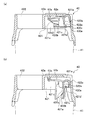
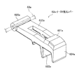
図7は図4におけるSec2−Sec2での断面図である。図8は傾倒規制板の斜視図である。図9はイースト容器が傾倒規制板に載置された状態を示す斜視図、図10の(a)は図4におけるSec3−Sec3での断面図、(b)はイースト容器が傾倒した状態を示す図である。また、図11はイースト投入レバーの斜視図である。   7 is a cross-sectional view taken along Sec2-Sec2 in FIG. FIG. 8 is a perspective view of the tilt regulating plate. 9 is a perspective view showing a state in which the yeast container is placed on the tilt regulating plate, FIG. 10A is a cross-sectional view of Sec3-Sec3 in FIG. 4, and FIG. 9B shows a state in which the yeast container is tilted. FIG. FIG. 11 is a perspective view of the yeast charging lever.

図7に示すように、第二切欠部423bの位置(天面部42aの下面側)には具材投入レバー62bが備わる。具材投入レバー62bは一方の副室425bに配置される。具材投入レバー62bは、第二切欠部423bの位置から主隔壁42c1の側に向かって延設される。具材投入レバー62bは、主隔壁42c1の側の端部が第二レバー軸63bで回動自在に軸支される。第二レバー軸63bは副隔壁42c2で支持される。
具材投入レバー62bには復帰バネ64bが接続されている。復帰バネ64bの一端は具材投入レバー62bに係合され他端は底板426に係合される。復帰バネ64bは、具材投入レバー62bを第二切欠部423bの側に付勢する。具材投入レバー62bの端部(押下端621b)が第二切欠部423bを介して天面部42aに露出する。
As shown in FIG. 7, the material insertion lever 62b is provided at the position of the second notch 423b (the lower surface side of the top surface 42a). The material input lever 62b is disposed in one sub chamber 425b. The material input lever 62b extends from the position of the second notch 423b toward the main partition wall 42c1. The material input lever 62b is pivotally supported by the second lever shaft 63b so that the end portion on the main partition wall 42c1 side is rotatable. The second lever shaft 63b is supported by the sub partition wall 42c2.
A return spring 64b is connected to the material input lever 62b. One end of the return spring 64b is engaged with the material loading lever 62b, and the other end is engaged with the bottom plate 426. The return spring 64b biases the material loading lever 62b toward the second notch 423b. An end portion (pressing end 621b) of the material loading lever 62b is exposed to the top surface portion 42a through the second notch portion 423b.

具材投入レバー62bには、押下端621bが下方に押し下げられたときに第二の具材投入手段422の側に突出する爪部622bが形成されている。爪部622dは、主隔壁42c1に形成される切欠溝42c3を挿通して第二の具材投入手段422に突出する。
第二の具材投入手段422は、爪部622bが突出したときに、第二具材容器440(図4参照)が保持している食材A2(図4参照)をパン焼成容器41(図3参照)に落下するように構成される。
なお、第二の具材投入手段422(図4に示す第二具材容器440)が保持する食材A2をパン焼成容器41に落下するための構造は、前記した特許文献1に記載される構造を適用可能である。
The material loading lever 62b is formed with a claw portion 622b that protrudes toward the second material loading means 422 when the pressing end 621b is pushed downward. The nail | claw part 622d penetrates the notch groove 42c3 formed in the main partition 42c1, and protrudes in the 2nd material injection | throwing-in means 422.
When the nail | claw part 622b protrudes, the 2nd material injection | throwing-in means 422 makes the bread baking container 41 (FIG. 3) the foodstuff A2 (refer FIG. 4) which the 2nd material container 440 (refer FIG. 4) hold | maintains. Configured to fall).
The structure for dropping the food material A2 held by the second material input means 422 (second material container 440 shown in FIG. 4) into the bread baking container 41 is the structure described in Patent Document 1 described above. Is applicable.

図8に示すように、傾倒規制板421cは、軸部430aと支持面部430bと係合爪430c(係合部材)とを有する。軸部430aは、支持面回動軸421dに遊嵌する。支持面部430bは、軸部430aから支持面回動軸421dと直交する方向に平面状に張り出して形成される。係合爪430cは、軸部430aから支持面回動軸421dと直交する方向に突出する。
支持面部430bは、イースト容器421a(図6の(a)参照)の下方に張り出して、当該イースト容器421aを下方から支持する。なお、支持面部430bの上面(イースト容器421aを支持する面)には凸状部430dが形成されている。
凸状部430dはイースト容器421aの底部に当接して当該イースト容器421aを下方から支持する。
As shown in FIG. 8, the tilt regulating plate 421c has a shaft portion 430a, a support surface portion 430b, and an engaging claw 430c (engaging member). The shaft portion 430a is loosely fitted to the support surface rotation shaft 421d. The support surface portion 430b is formed to project in a planar shape from the shaft portion 430a in a direction orthogonal to the support surface rotation shaft 421d. The engaging claw 430c protrudes from the shaft portion 430a in a direction orthogonal to the support surface rotation shaft 421d.
The support surface portion 430b projects below the yeast container 421a (see FIG. 6A) and supports the yeast container 421a from below. In addition, the convex part 430d is formed in the upper surface (surface which supports the yeast container 421a) of the support surface part 430b.
The convex portion 430d abuts on the bottom of the yeast container 421a and supports the yeast container 421a from below.

また、軸部430aには、支持面回動軸421dと直交する方向に突起部(押圧突起430e)が突設されている。押圧突起430eの詳細は後記する。   Further, the shaft portion 430a is provided with a protrusion (a pressing protrusion 430e) in a direction perpendicular to the support surface rotation shaft 421d. Details of the pressing protrusion 430e will be described later.

図8に示すように、傾倒規制板421cの軸部430aは支持面回動軸421dを覆うように配設される。軸部430aは支持面回動軸421dに遊嵌され、傾倒規制板421cは支持面回動軸421d周りに回動可能に支持される。
また、図8に示すように、軸部430aにはコイルばね431が巻きつけられている。コイルばね431は、支持面部430bがイースト容器421aを下方から押圧するように傾倒規制板421cを付勢する。コイルばね431は、支持面部430bと底板426との間でねじられ、支持面部430bが底板426から離反する方向に支持面部430bを付勢する。
そして、図6の(a)に示すように、イースト容器421aの上端部が、具材容器42の天面部42aに下方から当接する構成とすれば、イースト容器421aは傾倒規制板421c(支持面部430b)によって下方から天面部42aの下面に押し付けられる。このとき、イースト容器421aが天面部42aに対して正立するように構成される。
本実施例において、イースト容器421aの開口部が上方を向いた状態(つまり、開口部が天面部42aの側を向いた状態)をイースト容器421aの正立状態とする。
As shown in FIG. 8, the shaft portion 430a of the tilt regulating plate 421c is disposed so as to cover the support surface rotation shaft 421d. The shaft portion 430a is loosely fitted to the support surface rotation shaft 421d, and the tilt regulating plate 421c is supported to be rotatable around the support surface rotation shaft 421d.
Further, as shown in FIG. 8, a coil spring 431 is wound around the shaft portion 430a. The coil spring 431 biases the tilt regulating plate 421c so that the support surface portion 430b presses the yeast container 421a from below. The coil spring 431 is twisted between the support surface portion 430b and the bottom plate 426, and biases the support surface portion 430b in a direction in which the support surface portion 430b is separated from the bottom plate 426.
Then, as shown in FIG. 6 (a), if the upper end portion of the yeast container 421a is configured to come into contact with the top surface portion 42a of the ingredient container 42 from below, the yeast container 421a is inclined to the tilt regulating plate 421c (support surface portion). 430b) is pressed against the lower surface of the top surface portion 42a from below. At this time, the yeast container 421a is configured to stand upright with respect to the top surface portion 42a.
In the present embodiment, the state where the opening of the yeast container 421a faces upward (that is, the state where the opening faces the side of the top surface part 42a) is defined as the upright state of the yeast container 421a.

図9に示すように、容器回動軸421bで軸支されるイースト容器421aは、支持面回動軸421dで軸支される傾斜規制板421cの上方に配置される。イースト容器421aは、容器回動軸421b周りに自在に回動して容器本体420aが支持面部430bに載置される。このとき、傾斜規制板421cの押圧突起430eが、イースト容器421aの係合爪420cの下方に接するように構成される。
なお、容器本体420aの底部に、凸状部430dが嵌まり込む凹部420dが形成されていてもよい。
As shown in FIG. 9, the yeast container 421a pivotally supported by the container pivoting shaft 421b is disposed above the inclination regulating plate 421c pivotally supported by the support surface pivoting shaft 421d. The yeast container 421a freely rotates around the container rotation shaft 421b, and the container body 420a is placed on the support surface portion 430b. At this time, the pressing protrusion 430e of the inclination regulating plate 421c is configured to be in contact with the lower side of the engaging claw 420c of the yeast container 421a.
In addition, the recessed part 420d in which the convex-shaped part 430d fits may be formed in the bottom part of the container main body 420a.

図10の(a)に示すように、第一切欠部423aの位置(天面部42aの下面側)にはイースト投入レバー62a(レバー部材)が備わる。イースト投入レバー62aは、第一切欠部423aの位置から第二の具材投入手段422の側に向かって延設される。イースト投入レバー62aは、第二の具材投入手段422の側の端部が第一レバー軸63aによって回動自在に支持される。第一レバー軸63aは、副隔壁42c2に支持される。
イースト投入レバー62aが天面部42aの側に回動したとき、イースト投入レバー62aの端部(押下端621a)が第一切欠部423aを介して天面部42aに露出する。
また、イースト投入レバー62aの下方には係合部622aが形成されている。
As shown in FIG. 10A, a yeast insertion lever 62a (lever member) is provided at the position of the first notch 423a (the lower surface side of the top surface portion 42a). The yeast throwing lever 62a extends from the position of the first notch 423a toward the second ingredient throwing means 422. The end portion on the second material input means 422 side of the yeast input lever 62a is rotatably supported by the first lever shaft 63a. The first lever shaft 63a is supported by the sub partition wall 42c2.
When the yeast throwing lever 62a rotates toward the top surface portion 42a, the end portion (pressing end 621a) of the yeast throwing lever 62a is exposed to the top surface portion 42a through the first notch 423a.
An engaging portion 622a is formed below the yeast throwing lever 62a.

図11に示すように、イースト投入レバー62aは、軸支部620aとアーム部623aとを有する。軸支部620aは第一レバー軸63aに遊嵌される。アーム部623aは軸支部620aから延設される。アーム部623aの先端部が肉厚に盛り上がって押下端621aが形成される。また、アーム部632aに対して押下端621aが盛り上がる方向と逆方向に係合部622aが突設される。図10の(a)に示すように、係合部622aは、傾倒規制板421cの係合爪430cと係合する。したがって、係合部622aは、傾倒規制板421cの係合爪430cと係合可能な位置に形成される。
なお、イースト投入レバー62aの先端部には、押下端621aと逆方向に垂れ下がる端壁部624aが形成されている。端壁部624aは、第一切欠部423a(図10の(a)参照)を塞いで、第一の具材投入手段421への異物(ゴミなど)の侵入を防止する。
As shown in FIG. 11, the yeast throwing lever 62a has a shaft support portion 620a and an arm portion 623a. The shaft support 620a is loosely fitted to the first lever shaft 63a. The arm portion 623a extends from the shaft support portion 620a. A tip end portion of the arm portion 623a swells thickly to form a pressing end 621a. In addition, an engaging portion 622a protrudes from the arm portion 632a in a direction opposite to the direction in which the pressing end 621a rises. As shown to (a) of FIG. 10, the engaging part 622a engages with the engaging nail | claw 430c of the inclination control board 421c. Therefore, the engaging portion 622a is formed at a position where it can engage with the engaging claw 430c of the tilt regulating plate 421c.
An end wall portion 624a that hangs down in the opposite direction to the pressing end 621a is formed at the tip of the yeast throwing lever 62a. The end wall portion 624a completely blocks the first notch portion 423a (see FIG. 10A) to prevent entry of foreign matter (such as dust) into the first material input unit 421.

図10の(b)に示すように、係合部622aの下方への変位に応じて係合爪430cが軸部430aを回動させ、それにともなって支持面部430bが下方に回動してイースト容器421aから離反する。この構成によって、イースト投入レバー62aの押下端621aが押し下げられると、支持面部430bが下方に回動してイースト容器421aから離反する。支持面部430bがイースト容器421aから離反すると、イースト容器421aは自重で容器回動軸421b周りに回動し、天面部42aに対して傾倒する。これによって、イースト容器421aは正立状態から傾倒する。   As shown in FIG. 10 (b), the engaging claw 430c rotates the shaft portion 430a in accordance with the downward displacement of the engaging portion 622a, and accordingly, the support surface portion 430b rotates downward and the yeast. Separate from the container 421a. With this configuration, when the push-down end 621a of the yeast loading lever 62a is pushed down, the support surface portion 430b rotates downward and separates from the yeast container 421a. When the support surface part 430b is separated from the yeast container 421a, the yeast container 421a rotates around the container rotation shaft 421b by its own weight and tilts with respect to the top surface part 42a. As a result, the yeast container 421a tilts from the upright state.

なお、図6の(a)に示すように、容器回動軸421bが支持面回動軸421dよりも主隔壁42c1側かつ上方に配置されることによって、イースト容器421aは、傾倒規制板421cよりも高い位置を支点として回動する。
したがって、図10の(b)に示すようにイースト容器421aが傾倒したとき、下端となる位置が高くなる。
これによって、パン焼成容器41(図3参照)内で膨らんだパン生地B(図3参照)と傾倒したイースト容器421aとの接触が避けられる。
As shown in FIG. 6A, the container rotation shaft 421b is disposed on the main partition wall 42c1 side and above the support surface rotation shaft 421d, so that the yeast container 421a is tilted from the tilt regulating plate 421c. Rotate with the higher position as a fulcrum.
Therefore, when the yeast container 421a is tilted as shown in FIG.
This avoids contact between the bread dough B (see FIG. 3) swollen in the bread baking container 41 (see FIG. 3) and the tilted yeast container 421a.

また、図6の(a),(b)に示すように、容器回動軸421bが、イースト容器421aの容器本体420aの開口部の外形よりも内側、かつ、容器本体420aの底部よりも上方(開口部側)に配置される。このような構成とすることでイースト容器421aが傾倒するときの回動半径が小さくなる。したがって、第一の具材投入手段421を小さくでき、ひいては、具材容器42を小型化できる。   Further, as shown in FIGS. 6A and 6B, the container rotation shaft 421b is inside the outer shape of the opening of the container main body 420a of the yeast container 421a and above the bottom of the container main body 420a. It is arranged on the (opening side). By setting it as such a structure, the turning radius when the yeast container 421a tilts becomes small. Therefore, the first material input means 421 can be reduced, and the material container 42 can be reduced in size.

イースト投入レバー62aにおける押下端621aの押し下げが解除されると、傾倒規制板421cは、コイルばね431(図8参照)によってイースト容器421aを押し上げる方向に回動する。イースト容器421aは、開口部が上方を向いて正立状態になる。   When the push-down end 621a of the yeast loading lever 62a is released from being pushed down, the tilt regulating plate 421c is rotated in the direction of pushing up the yeast container 421a by the coil spring 431 (see FIG. 8). The yeast container 421a is in an upright state with the opening facing upward.

図12の(a)はイースト容器が傾倒していない状態の具材容器の下方を示す斜視図、(b)はイースト容器が傾倒した状態の具材容器の下方を示す斜視図である。
図10の(a)に示すイースト投入レバー62aの押下端621aが押し下げられていないとき、図12の(a)に示すように、イースト容器421aの下方に傾倒規制板421cが配置され、イースト容器421aは正立状態になっている。
図10の(b)に示すようにイースト投入レバー62aの押下端621aが押し下げられると、図12の(b)に示すように、傾倒規制板421cが下方に回動して底板426の落下孔426aに入り込みイースト容器421aから離反する。これによって、イースト容器421aは容器回動軸421b(図6の(a)参照)周りに回動して傾倒し、落下孔426aに入り込む。イースト容器421aの開口部は落下孔426aを通って下方を向く。したがって、イースト容器421aに保持されるドライイーストA1(図3参照)は底板426の下方に落下する。図3に示すように、具材容器42がパン焼成容器41の上方に取り付けられていると、ドライイーストA1はパン焼成容器41の内部に落下投入される。
(A) of FIG. 12 is a perspective view showing the lower part of the ingredient container in a state where the yeast container is not tilted, and (b) is a perspective view showing the lower part of the ingredient container in a state where the yeast container is tilted.
When the pressing end 621a of the yeast loading lever 62a shown in FIG. 10 (a) is not pushed down, as shown in FIG. 12 (a), a tilt regulating plate 421c is arranged below the yeast container 421a, and the yeast container 421a is in an upright state.
When the pressing end 621a of the yeast loading lever 62a is pushed down as shown in FIG. 10 (b), the tilt regulating plate 421c is rotated downward as shown in FIG. 426a enters and leaves the yeast vessel 421a. As a result, the yeast container 421a rotates and tilts around the container rotation shaft 421b (see FIG. 6A) and enters the drop hole 426a. The opening of the yeast container 421a faces downward through the drop hole 426a. Accordingly, the dry yeast A1 (see FIG. 3) held in the yeast container 421a falls below the bottom plate 426. As shown in FIG. 3, when the ingredient container 42 is attached above the bread baking container 41, the dry yeast A1 is dropped into the bread baking container 41.

このように、具材容器42は、イースト投入レバー62aの押下端621aが押し下げられると、イースト容器421aが天面部42aに対して傾倒する。また、押下端621aの押し下げが解除されると、イースト容器421aは開口部が上方を向いて正立状態になる。   As described above, when the pressing end 621a of the yeast loading lever 62a is pushed down, the yeast container 421a is tilted with respect to the top surface portion 42a. When the pressing end 621a is released, the yeast container 421a is in an upright state with the opening facing upward.

図13は、第一の具材投入手段及び第二の具材投入手段を操作する具材投入操作機構の斜視図である。
図13に示すように、本実施例の加熱調理器10の本体1には具材投入操作機構47が備わっている。具材投入操作機構47は、第一の具材投入手段421を操作する第一具材投入操作機構47aと、第二の具材投入手段422を操作する第二具材投入操作機構47bを有する。
FIG. 13 is a perspective view of a material loading operation mechanism for operating the first material loading device and the second material loading device.
As shown in FIG. 13, the main body 1 of the heating cooker 10 of the present embodiment is provided with an ingredient charging operation mechanism 47. The material input operation mechanism 47 includes a first material input operation mechanism 47a for operating the first material input means 421 and a second material input operation mechanism 47b for operating the second material input means 422. .

第一具材投入操作機構47aは、第一プッシュロッド470aと、第一ソレノイド471aと、第一復帰ばね472aと、第一リンク部材473aと、アーム部材(第一押下アーム474a)と、を有する。第一プッシュロッド470aは、本体1に対して上下動可能に備わる。第一プッシュロッド470aの下端には第一リンク部材473aが回動自在に取り付けられている。第一リンク部材473aは、一端が第一プッシュロッド470aに取り付けられ、他端が第一ソレノイド471aに連結される。また、第一リンク部材473aは一端と他端の間が回動軸で回動自在に支持される。   The first material input operation mechanism 47a includes a first push rod 470a, a first solenoid 471a, a first return spring 472a, a first link member 473a, and an arm member (first pressing arm 474a). . The first push rod 470 a is provided so as to be movable up and down with respect to the main body 1. A first link member 473a is rotatably attached to the lower end of the first push rod 470a. The first link member 473a has one end attached to the first push rod 470a and the other end connected to the first solenoid 471a. Further, the first link member 473a is rotatably supported between one end and the other end by a rotation shaft.

第一復帰ばね472aは、第一ソレノイド471aと連結される他端を上方に引き付けるように第一リンク部材473aを付勢する。第一リンク部材473aは、第一復帰ばね472aによって他端が上方に引き付けられると、第一プッシュロッド470aが接続される一端が下方に変位して第一プッシュロッド470aを下方に変位させる。
通電された第一ソレノイド471aが第一リンク部材473aの他端を下方に引き付けると、第一リンク部材473aにおいて第一プッシュロッド470aが接続される一端が上方に変位する。これによって第一プッシュロッド470aが上方に変位する。
The first return spring 472a biases the first link member 473a so as to attract the other end connected to the first solenoid 471a upward. When the other end of the first link member 473a is attracted upward by the first return spring 472a, one end to which the first push rod 470a is connected is displaced downward to displace the first push rod 470a downward.
When the energized first solenoid 471a attracts the other end of the first link member 473a downward, one end of the first link member 473a to which the first push rod 470a is connected is displaced upward. As a result, the first push rod 470a is displaced upward.

このように、第一ソレノイド471aに通電されると第一プッシュロッド470aが上方に変位し、第一ソレノイド471aへの通電が停止すると第一プッシュロッド470aが下方に変位する。
第一プッシュロッド470aの上端に第一押下アーム474aが連結される。第一押下アーム474aは、第一プッシュロッド470aの上方への変位(上動)及び下方への変位(下動)を反転させるリンク機構を構成する。
また、本実施例の第一ソレノイド471aは、第一押下アーム474aを駆動するアクチュエータとして機能する。
Thus, when the first solenoid 471a is energized, the first push rod 470a is displaced upward, and when the energization to the first solenoid 471a is stopped, the first push rod 470a is displaced downward.
The first push arm 474a is connected to the upper end of the first push rod 470a. The first push-down arm 474a constitutes a link mechanism that reverses the upward displacement (upward movement) and the downward displacement (downward movement) of the first push rod 470a.
Further, the first solenoid 471a of this embodiment functions as an actuator that drives the first pressing arm 474a.

第一押下アーム474aの一端に第一プッシュロッド470aが連結される。第一押下アーム474aは、第一プッシュロッド470aが連結される一端と、他端と、の間が回動軸(図示せず)で回動自在に軸支される。第一プッシュロッド470aが上方に変位すると第一押下アーム474aの一端は上方に変位する。このとき、第一押下アーム474aは回動軸周りに回動して他端が下方に変位する。   A first push rod 470a is connected to one end of the first push arm 474a. The first push arm 474a is pivotally supported by a pivot shaft (not shown) between one end to which the first push rod 470a is connected and the other end. When the first push rod 470a is displaced upward, one end of the first push arm 474a is displaced upward. At this time, the first pressing arm 474a rotates around the rotation axis and the other end is displaced downward.

第一押下アーム474aの他端は、具材容器42の第一切欠部423aの上方に配置される。そして、第一押下アーム474aの他端が下方に変位したときにイースト投入レバー62aの押下端621aを押下する。図10の(b)に示すように、イースト投入レバー62aが押下されるとイースト容器421aが傾倒する。
このように、第一押下アーム474aは、第一プッシュロッド470aを介して第一ソレノイド471aで駆動してイースト投入レバー62aを押下する。
つまり、図13に示す第一具材投入操作機構47aは、第一ソレノイド471aの動作で、具材容器42のイースト容器421a(図10の(b)参照)を傾倒させる。そして、本実施例においては、傾倒規制板421cの係合爪430c(図8参照)と、イースト投入レバー62a(図10の(a)参照)と、第一押下アーム474aと、によって、支持面部430b(図10の(a)参照)を支持面回動軸421d(図10の(a)参照)周りに回動させる回動機構が構成される。
The other end of the first push-down arm 474a is disposed above the first notch 423a of the material container 42. When the other end of the first pressing arm 474a is displaced downward, the pressing end 621a of the yeast throwing lever 62a is pressed. As shown in FIG. 10B, the yeast container 421a tilts when the yeast loading lever 62a is pressed.
As described above, the first pressing arm 474a is driven by the first solenoid 471a via the first push rod 470a to press the yeast loading lever 62a.
That is, the first ingredient charging operation mechanism 47a shown in FIG. 13 tilts the yeast container 421a (see FIG. 10B) of the ingredient container 42 by the operation of the first solenoid 471a. In the present embodiment, the support surface portion is constituted by the engagement claw 430c (see FIG. 8) of the tilt regulating plate 421c, the yeast throwing lever 62a (see (a) of FIG. 10), and the first pressing arm 474a. A rotation mechanism that rotates 430b (see FIG. 10A) around the support surface rotation shaft 421d (see FIG. 10A) is configured.

図13に示すように、第二具材投入操作機構47bは、第二プッシュロッド470bと、第二ソレノイド471bと、第二復帰ばね472bと、第二リンク部材473bと、第二押下アーム474bと、を有する。第二具材投入操作機構47bは、第一具材投入操作機構47aと同等の構造を呈する。
第二具材投入操作機構47bは、第二ソレノイド471bの動作で第二プッシュロッド470bが上方に変位したときに、具材容器42の具材投入レバー62b(押下端621b)を押圧して第二の具材投入手段422が保持する食材A2(図3参照)をパン焼成容器41に落下させる。
As shown in FIG. 13, the second material loading operation mechanism 47b includes a second push rod 470b, a second solenoid 471b, a second return spring 472b, a second link member 473b, and a second push-down arm 474b. Have. The second material charging operation mechanism 47b has the same structure as the first material charging operation mechanism 47a.
The second material loading operation mechanism 47b presses the material loading lever 62b (pressing end 621b) of the material container 42 when the second push rod 470b is displaced upward by the operation of the second solenoid 471b. The food A2 (see FIG. 3) held by the second ingredient charging means 422 is dropped into the bread baking container 41.

前記したように、加熱調理器10を制御する制御装置6(図1参照)は、パンの焼成時における練り工程でドライイーストA1(図3参照)をパン焼成容器41(図3参照)に落下投入する。
つまり、制御装置6は、練り工程における所定のタイミングで第一ソレノイド471aに指令を与えて第一プッシュロッド470aを上動させる。これによって、第一押下アーム474aがイースト投入レバー62aの押下端621aを押下し、イースト容器421aが傾倒する。そして、イースト容器421aに保持されているドライイーストA1がパン焼成容器41の広範囲に落下投入される。
なお、制御装置6は、練り工程における所定のタイミングで第二ソレノイド471bに指令を与えて第二プッシュロッド470bを上動させる。これによって、第二押下アーム474bが具材投入レバー62bの押下端621bを押下し、第二の具材投入手段422(図3参照)が保持する食材A2(図3参照)がパン焼成容器41に落下投入される。
As described above, the control device 6 (see FIG. 1) for controlling the heating cooker 10 drops the dry yeast A1 (see FIG. 3) into the bread baking container 41 (see FIG. 3) in the kneading process at the time of baking bread. throw into.
That is, the control device 6 gives a command to the first solenoid 471a at a predetermined timing in the kneading process to move the first push rod 470a upward. As a result, the first pressing arm 474a presses the pressing end 621a of the yeast loading lever 62a, and the yeast container 421a tilts. Then, the dry yeast A1 held in the yeast container 421a is dropped into a wide range of the bread baking container 41.
The control device 6 gives a command to the second solenoid 471b at a predetermined timing in the kneading process to move the second push rod 470b upward. As a result, the second pressing arm 474b presses the pressing end 621b of the ingredient throwing lever 62b, and the food A2 (see FIG. 3) held by the second ingredient throwing means 422 (see FIG. 3) becomes the bread baking container 41. Is dropped into.

図14は、押圧突起の機能を説明する図である。
図14に示すように、イースト容器421aには、容器回動軸421b周りに回動する係合爪420cが形成されている。図14に二点鎖線で示すように、係合爪420cは、イースト容器421aが傾倒するときに上昇する方向に回動する。また、イースト投入レバー62a(図10の(a)参照)が押圧されずに傾倒規制板421cが回動していない状態のとき、係合爪420cの下方に接するように押圧突起430eが配置される。押圧突起430eは、支持面部430b(イースト容器421aが載置される面)に対する角度θ1が90度より大きく形成されている(θ1>90度)。そして、イースト投入レバー62aの押下端621a(図10の(a)参照)が押圧されて傾倒規制板421cが回動するときに押圧突起430eが係合爪420cを下方から押圧して持ち上げるように構成される。
FIG. 14 is a diagram illustrating the function of the pressing protrusion.
As shown in FIG. 14, the yeast container 421a is formed with an engaging claw 420c that rotates around the container rotation shaft 421b. As shown by a two-dot chain line in FIG. 14, the engaging claw 420 c rotates in a direction that rises when the yeast container 421 a tilts. In addition, when the yeast throwing lever 62a (see FIG. 10A) is not pressed and the tilt restricting plate 421c is not rotating, the pressing protrusion 430e is disposed so as to contact the lower side of the engaging claw 420c. The The pressing protrusion 430e has an angle θ1 with respect to the support surface portion 430b (the surface on which the yeast container 421a is placed) larger than 90 degrees (θ1> 90 degrees). Then, when the pressing end 621a (see FIG. 10A) of the yeast loading lever 62a is pressed and the tilt restricting plate 421c rotates, the pressing protrusion 430e presses the engaging claw 420c from below to lift it. Composed.

図6の(a)に示すように、イースト容器421aは開口部側の上端が具材容器42の天面部42aに下方から当接する。例えば、乾燥したパン生地B(図3参照)がイースト容器421aの端部に付着してイースト容器421aの端部が天面部42aに固着すると、図10の(b)に示すように傾倒規制板421cの支持面部430bが下方に回動してもイースト容器421aが傾倒しない。イースト容器421aが傾倒しないと、イースト容器421aが保持しているドライイーストA1(図3参照)がパン焼成容器41(図3参照)に落下しない。   As shown in FIG. 6A, the upper end of the opening side of the yeast container 421a contacts the top surface part 42a of the ingredient container 42 from below. For example, when the dried bread dough B (see FIG. 3) adheres to the end of the yeast container 421a and the end of the yeast container 421a adheres to the top surface 42a, the tilt regulating plate 421c as shown in FIG. 10 (b). Even if the support surface portion 430b rotates downward, the yeast container 421a does not tilt. If the yeast container 421a does not tilt, the dry yeast A1 (see FIG. 3) held by the yeast container 421a will not fall into the bread baking container 41 (see FIG. 3).

図14に示すように、傾倒規制板421cが回動するときに押圧突起430eが係合爪420cを下方から押圧して持ち上げる構成であれば、傾倒規制板421cの回動に応じてイースト容器421aを傾倒させる力が発生する。したがって、イースト容器421aの上端が天面部42aに固着した状態であっても傾倒規制板421cの回動に応じてイースト容器421aを傾倒させることができる。これによって、イースト容器421aに保持されるドライイーストA1(図3参照)がパン焼成容器41(図3参照)に落下しないという不具合の発生が回避される。   As shown in FIG. 14, when the tilt restricting plate 421c rotates, the pressing protrusion 430e presses and lifts the engaging claw 420c from below to lift the yeast container 421a according to the rotation of the tilt restricting plate 421c. Force to tilt is generated. Therefore, even if the upper end of the yeast container 421a is fixed to the top surface part 42a, the yeast container 421a can be tilted according to the rotation of the tilt regulating plate 421c. This avoids the occurrence of a problem that the dry yeast A1 (see FIG. 3) held in the yeast container 421a does not fall into the bread baking container 41 (see FIG. 3).

本実施例の加熱調理器10は、図1に示すようにベーカリー手段40を備えてパンの焼成が可能に構成されている。図3に示すように、ベーカリー手段40は具材容器42を備える。図4に示すように、具材容器42はドライイーストA1を保持する第一の具材投入手段421を備え、パン焼成容器41にドライイーストA1を投入可能となっている。
図10の(b)に示すように、第一の具材投入手段421は、ドライイーストA1(図3参照)を保持するイースト容器421aが傾倒する。そして、イースト容器421aに保持されるドライイーストA1は、イースト容器421aの傾倒に応じて上端の開口部から落下する。
イースト容器421aは上端部が大きく開口している。したがって、ドライイーストA1はパン焼成容器41内のパン生地B(図3参照)の上部表面全体に落下し、前記した練り工程においてパン生地BとドライイーストA1とが効率よく混ぜ合わせられる。また、ドライイーストA1が吸湿して大きな塊状になっても全てのドライイーストA1がパン焼成容器41に落下投入される。このため、パン焼成容器41に投入されるドライイーストA1が不足するという事象の発生は防止される。
The cooking device 10 according to the present embodiment includes a bakery means 40 as shown in FIG. 1 and is configured to be capable of baking bread. As shown in FIG. 3, the bakery means 40 includes an ingredient container 42. As shown in FIG. 4, the ingredient container 42 includes first ingredient input means 421 that holds the dry yeast A <b> 1, and the dry yeast A <b> 1 can be input into the bread baking container 41.
As shown in FIG. 10 (b), in the first ingredient charging means 421, the yeast container 421a holding the dry yeast A1 (see FIG. 3) is tilted. And the dry yeast A1 hold | maintained at the yeast container 421a falls from the opening part of an upper end according to tilting of the yeast container 421a.
The upper end of the yeast container 421a is greatly open. Therefore, the dry yeast A1 falls on the entire upper surface of the bread dough B (see FIG. 3) in the bread baking container 41, and the bread dough B and the dry yeast A1 are efficiently mixed in the kneading process described above. Even if the dry yeast A1 absorbs moisture and becomes a large lump, all the dry yeast A1 is dropped into the bread baking container 41. For this reason, generation | occurrence | production of the event that the dry yeast A1 thrown into the bread baking container 41 runs short is prevented.

また、図10の(a)に示すように、イースト容器421aは傾倒規制板421cの支持面部430bに支持される。そして、イースト容器421aは、イースト投入レバー62aの押下端621aが押し下げられて支持面部430bが下方に回動したときに自重で傾倒する。
また、図13に示すように、押下端621aは第一ソレノイド471aで駆動する第一押下アーム474aで押し下げられる。そして、傾倒規制板421cの支持面部430bは、イースト容器421aの傾倒よりも速く回動する。したがって、傾倒するイースト容器421aは下方への回動が終了した状態の支持面部430bに衝突する。このとき、イースト容器421aは支持面部430bとの衝突でバウンドする。このようなバウンドは数回に亘って発生する。例えば、イースト容器421aに保持されるドライイーストA1(図3参照)の一部がイースト容器421aに固着していてもバウンドによる衝撃で振り落とされる。このため、ドライイーストA1はイースト容器421aに残留することなく全てがパン焼成容器41(図3参照)に投入される。このように、本実施例の具材容器42は、第一の具材投入手段421におけるドライイーストA1の残留を効果的に防止できる。
Moreover, as shown to (a) of FIG. 10, the yeast container 421a is supported by the support surface part 430b of the inclination control board 421c. The yeast container 421a is tilted by its own weight when the pressing end 621a of the yeast loading lever 62a is pushed down and the support surface portion 430b rotates downward.
As shown in FIG. 13, the pressing end 621a is pushed down by a first pressing arm 474a driven by a first solenoid 471a. And the support surface part 430b of the inclination control board 421c rotates faster than the inclination of the yeast container 421a. Therefore, the tilted yeast container 421a collides with the support surface portion 430b in a state where the downward rotation is finished. At this time, the yeast container 421a bounces by the collision with the support surface part 430b. Such a bounce occurs several times. For example, even if a part of the dry yeast A1 (see FIG. 3) held in the yeast container 421a is fixed to the yeast container 421a, it is shaken off by an impact due to bouncing. For this reason, the dry yeast A1 does not remain in the yeast container 421a, but is entirely put into the bread baking container 41 (see FIG. 3). Thus, the ingredient container 42 of the present embodiment can effectively prevent the dry yeast A1 from remaining in the first ingredient throwing means 421.

また、図14に示すように、傾倒規制板421cは押圧突起430eを有する。押圧突起430eは、傾倒規制板421cが回動するときにイースト容器421aの係合爪420cを下方から押圧して持ち上げる。係合爪420cが持ち上がるとイースト容器421aが傾倒する。例えば、イースト容器421aの上端部が天面部42a(図6の(a)参照)に固着してイースト容器421aが自重で傾倒できない状態であっても、イースト容器421aを傾倒させる力が生じる。この力によってイースト容器421aと天面部42aの固着が解消すれば、イースト容器421aは自重で傾倒する。
本実施例の具材容器42は、自重で傾倒できない状態のイースト容器421aを傾倒させることができ、ドライイーストA1(図3参照)がパン焼成容器41に投入されないという不具合の発生を防止できる。
In addition, as shown in FIG. 14, the tilt regulating plate 421c has a pressing protrusion 430e. The pressing protrusion 430e presses and lifts the engaging claw 420c of the yeast container 421a from below when the tilt regulating plate 421c rotates. When the engaging claw 420c is lifted, the yeast container 421a is tilted. For example, even when the upper end portion of the yeast container 421a is fixed to the top surface portion 42a (see FIG. 6A) and the yeast container 421a cannot be tilted by its own weight, a force for tilting the yeast container 421a is generated. If the adhesion between the yeast container 421a and the top surface part 42a is eliminated by this force, the yeast container 421a is tilted by its own weight.
The material container 42 of the present embodiment can tilt the yeast container 421a that cannot be tilted by its own weight, and can prevent the occurrence of the problem that the dry yeast A1 (see FIG. 3) is not put into the bread baking container 41.

また、図6の(a)に示すように、本実施例のイースト容器421aは底面に開口を有さない。したがって、高湿な環境でパンの焼成がタイマー予約され、ドライイーストA1(図3参照)が長時間に亘ってイースト容器421aに保持される状態であっても、イースト容器421aへの高湿な空気の流入が抑制される。このように、本実施例のイースト容器421aは、ドライイーストA1が吸湿しにくい構造になっている。   Moreover, as shown to (a) of FIG. 6, the yeast container 421a of a present Example does not have an opening in a bottom face. Therefore, even if the baking of the bread is reserved in the high humidity environment and the dry yeast A1 (see FIG. 3) is held in the yeast container 421a for a long time, the high humidity to the yeast container 421a is maintained. Air inflow is suppressed. Thus, the yeast container 421a of the present embodiment has a structure in which the dry yeast A1 hardly absorbs moisture.

なお、本発明は前記した実施例に限定されるものではない。例えば、前記した実施例は本発明をわかりやすく説明するために詳細に説明したものであり、必ずしも説明した全ての構成を備えるものに限定されるものではない。
また、ある実施例の構成の一部を他の実施例の構成に置き換えることも可能であり、また、ある実施例の構成に他の実施例の構成を加えることも可能である。
In addition, this invention is not limited to an above-described Example. For example, the above-described embodiments have been described in detail for easy understanding of the present invention, and are not necessarily limited to those having all the configurations described.
Further, a part of the configuration of a certain embodiment can be replaced with the configuration of another embodiment, and the configuration of another embodiment can be added to the configuration of a certain embodiment.

例えば、図10の(a),(b)に示すように、本実施例のイースト投入レバー62aは、傾倒規制板421cを回動させ、イースト容器421aは、傾倒規制板421cが回動したときに自重で傾倒するように構成されている。このような構成に限定されず、イースト投入レバー62aがイースト容器421aを傾倒させる構成であってもよい。この場合、傾倒規制板421cが不要になり、具材容器42の構造を簡素化できる。   For example, as shown in FIGS. 10A and 10B, the yeast insertion lever 62a of the present embodiment rotates the tilt restricting plate 421c, and the yeast container 421a rotates when the tilt restricting plate 421c rotates. It is configured to tilt with its own weight. It is not limited to such a structure, The structure which the yeast throwing lever 62a tilts the yeast container 421a may be sufficient. In this case, the tilt regulating plate 421c is not necessary, and the structure of the material container 42 can be simplified.

また、第二の具材投入手段422についても、図示しない容器が傾倒して、レーズンなどの食材A2(図3参照)がパン焼成容器41(図3参照)に落下投入される構成であってもよい。   In addition, the second ingredient throwing means 422 is also configured such that a container (not shown) is tilted and the food A2 such as raisins (see FIG. 3) is dropped into the bread baking container 41 (see FIG. 3). Also good.

この他、本発明は、前記した実施例に限定されるものではなく、発明の趣旨を逸脱しない範囲で適宜設計変更が可能である。   In addition, the present invention is not limited to the above-described embodiments, and appropriate design changes can be made without departing from the spirit of the invention.

例えば、本実施例では、図6の(a)に示すイースト容器421aは自重で容器回動軸421b周りに回動する構成とした。
この構成に替わり、図示しない付勢手段(ばね等)がイースト容器421aを付勢して回動する構成であってもよい。
又は、図示しないアクチュエータによってイースト容器421aが回動する構成であってもよい。
For example, in this embodiment, the yeast container 421a shown in FIG. 6A is configured to rotate around the container rotation shaft 421b by its own weight.
Instead of this configuration, an urging means (spring or the like) not shown may urge the yeast container 421a to rotate.
Or the structure which the yeast container 421a rotates by the actuator which is not shown in figure may be sufficient.

1 本体
6 制御装置
10 加熱調理器
40 ベーカリー手段(調理手段)
41 パン焼成容器(加熱容器)
42 具材容器
62a イースト投入レバー(レバー部材)
421 第一の具材投入手段(具材投入手段)
421a イースト容器(保持容器)
421b 容器回動軸(第2の回動軸)
421d 支持面回動軸(第1の回動軸)
430b 支持面部
430c 係合爪(係合部材,回動機構)
471a 第一ソレノイド(アクチュエータ)
474a 第一押下アーム(アーム部材,回動機構)
A1 ドライイースト(具材)
B パン生地
DESCRIPTION OF SYMBOLS 1 Main body 6 Control apparatus 10 Heating cooker 40 Bakery means (cooking means)
41 Bread baking container (heating container)
42 Material container 62a Yeast loading lever (lever member)
421 First material input means (material input means)
421a Yeast container (holding container)
421b Container rotation axis (second rotation axis)
421d Support surface rotation axis (first rotation axis)
430b Support surface part 430c Engagement claw (engagement member, rotation mechanism)
471a First solenoid (actuator)
474a First pressing arm (arm member, rotating mechanism)
A1 Dry yeast (ingredients)
B bread dough

Claims (4)

加熱する材料が入れられる加熱容器と、
前記加熱容器の上方に取り付けられる具材容器と、を有する調理手段が加熱室に装着され、
前記具材容器は、保持している具材を前記加熱容器に落下投入する具材投入手段を有し、
前記具材投入手段は
開口部が上方を向いた正立状態で前記具材を保持する保持容器と、
前記保持容器を前記正立状態で下方から支持する支持面部と、
前記支持面部を第1の回動軸周りに回動させて前記保持容器から離反させる回動機構と、を有し、
前記保持容器は、前記支持面部が離反したときに前記正立状態から第2の回動軸周りに回動して傾倒することで前記具材を前記加熱容器に落下投入するように構成したことを特徴とする加熱調理器。
A heating vessel in which the material to be heated is placed;
A cooking means having an ingredient container attached above the heating container is attached to the heating chamber,
The ingredient container has an ingredient throwing means for dropping the ingredient held into the heating container,
The ingredient dosing means is
A holding container that holds the ingredients in an upright state with the opening facing upward ;
A support surface portion for supporting the holding container from below in the upright state;
A rotation mechanism that rotates the support surface portion around a first rotation axis to move away from the holding container;
The holding container is configured to drop and throw the ingredients into the heating container by rotating around the second rotation axis from the upright state and tilting when the support surface part is separated. A cooking device characterized by.
前記保持容器は、自重で前記第2の回動軸周りに回動することを特徴とする請求項1に記載の加熱調理器。 The cooking device according to claim 1 , wherein the holding container rotates about the second rotation axis by its own weight. 前記回動機構は、
前記支持面部と一体に前記第1の回動軸周りに回動する係合部材と、
押下されたときに、前記支持面部が前記第1の回動軸周りに回動して前記保持容器から離反するように前記係合部材を押圧するレバー部材と、
アクチュエータで駆動して前記レバー部材を押下するアーム部材と、を有することを特徴とする請求項1または請求項2に記載の加熱調理器。
The rotation mechanism is
An engagement member that rotates about the first rotation axis integrally with the support surface portion;
A lever member that, when pressed, presses the engagement member so that the support surface portion rotates about the first rotation axis and separates from the holding container;
The cooking device according to claim 1 or claim 2, characterized in that it has a, an arm member for pressing said lever member is driven by an actuator.
前記調理手段がパンを焼成するためのベーカリー手段であり、
前記加熱容器に入れられて加熱される前記材料がパン生地であり、
前記保持容器に保持されて前記加熱容器に落下投入される前記具材がドライイーストであって、
前記パン生地を練る練り工程と、前記パン生地を発酵させる発酵工程と、前記パン生地を焼き上げる焼き上げ工程と、を順次実行してパンを焼成する制御装置を有し、
前記制御装置は、前記練り工程において前記アクチュエータに指令を与えて前記レバー部材を押下し、前記ドライイーストを前記加熱容器に落下投入することを特徴とする請求項3に記載の加熱調理器。
The cooking means is a bakery means for baking bread;
The material to be heated in the heating container is bread dough,
The ingredients that are held in the holding container and dropped into the heating container are dry yeast,
A controller for baking the bread by sequentially performing a kneading step for kneading the bread dough, a fermentation step for fermenting the bread dough, and a baking step for baking the bread dough,
The cooking device according to claim 3 , wherein the control device gives a command to the actuator in the kneading step, depresses the lever member, and drops the dry yeast into the heating container.
JP2014083030A 2014-04-14 2014-04-14 Cooker Active JP6192169B2 (en)

Priority Applications (2)

Application Number Priority Date Filing Date Title
JP2014083030A JP6192169B2 (en) 2014-04-14 2014-04-14 Cooker
TW103137019A TWI591297B (en) 2014-04-14 2014-10-27 Heating conditioner

Applications Claiming Priority (1)

Application Number Priority Date Filing Date Title
JP2014083030A JP6192169B2 (en) 2014-04-14 2014-04-14 Cooker

Publications (3)

Publication Number Publication Date
JP2015202202A JP2015202202A (en) 2015-11-16
JP2015202202A5 JP2015202202A5 (en) 2016-10-06
JP6192169B2 true JP6192169B2 (en) 2017-09-06

Family

ID=54596070

Family Applications (1)

Application Number Title Priority Date Filing Date
JP2014083030A Active JP6192169B2 (en) 2014-04-14 2014-04-14 Cooker

Country Status (2)

Country Link
JP (1) JP6192169B2 (en)
TW (1) TWI591297B (en)

Family Cites Families (1)

* Cited by examiner, † Cited by third party
Publication number Priority date Publication date Assignee Title
JP3191645B2 (en) * 1995-10-27 2001-07-23 松下電器産業株式会社 Automatic bread maker

Also Published As

Publication number Publication date
TWI591297B (en) 2017-07-11
TW201538907A (en) 2015-10-16
JP2015202202A (en) 2015-11-16

Similar Documents

Publication Publication Date Title
JPH09117375A (en) Automatic bread baking machine
US20120285336A1 (en) Automatic bread maker
US20130000491A1 (en) Automatic bread maker
JP2006255071A (en) Automated bread-making machine
JP6192169B2 (en) Cooker
JP5810325B2 (en) Automatic bread machine
US6729227B2 (en) Bread maker
JP2014083219A (en) Automatic bread maker
JP3807350B2 (en) Automatic bread machine
JP5957700B2 (en) Automatic bread machine
JP5974295B2 (en) Automatic bread machine
WO2012053247A1 (en) Container for holding bread ingredient and automatic bread-maker provided with same
JP6568015B2 (en) Secondary material storage container and automatic bread machine
JPH05309042A (en) Bread baking machine
JP7122594B2 (en) automatic bread machine
JP2589789B2 (en) Additive dropper for automatic bread maker
JP2008011984A (en) Bread maker
JP2011160958A (en) Automatic bread making machine
JP2011161216A (en) Automatic bread making machine
JP2004121542A (en) Automatic bread machine
JP2022155166A (en) home bread maker
JPH01141625A (en) Automatic bread maker
JPH0233249B2 (en)
JPH037119A (en) Yeast dropping device of automatic bread making machine
JP3714211B2 (en) Automatic bread machine

Legal Events

Date Code Title Description
A521 Written amendment

Free format text: JAPANESE INTERMEDIATE CODE: A523

Effective date: 20160822

A621 Written request for application examination

Free format text: JAPANESE INTERMEDIATE CODE: A621

Effective date: 20160822

A977 Report on retrieval

Free format text: JAPANESE INTERMEDIATE CODE: A971007

Effective date: 20170525

A131 Notification of reasons for refusal

Free format text: JAPANESE INTERMEDIATE CODE: A131

Effective date: 20170530

A521 Written amendment

Free format text: JAPANESE INTERMEDIATE CODE: A523

Effective date: 20170704

TRDD Decision of grant or rejection written
A01 Written decision to grant a patent or to grant a registration (utility model)

Free format text: JAPANESE INTERMEDIATE CODE: A01

Effective date: 20170725

A61 First payment of annual fees (during grant procedure)

Free format text: JAPANESE INTERMEDIATE CODE: A61

Effective date: 20170804

R150 Certificate of patent or registration of utility model

Ref document number: 6192169

Country of ref document: JP

Free format text: JAPANESE INTERMEDIATE CODE: R150

S533 Written request for registration of change of name

Free format text: JAPANESE INTERMEDIATE CODE: R313533

R350 Written notification of registration of transfer

Free format text: JAPANESE INTERMEDIATE CODE: R350