JP6190253B2 - Vibration generator - Google Patents
Vibration generator Download PDFInfo
- Publication number
- JP6190253B2 JP6190253B2 JP2013248230A JP2013248230A JP6190253B2 JP 6190253 B2 JP6190253 B2 JP 6190253B2 JP 2013248230 A JP2013248230 A JP 2013248230A JP 2013248230 A JP2013248230 A JP 2013248230A JP 6190253 B2 JP6190253 B2 JP 6190253B2
- Authority
- JP
- Japan
- Prior art keywords
- contact portion
- vibration
- vibration generating
- contact
- conductive pattern
- Prior art date
- Legal status (The legal status is an assumption and is not a legal conclusion. Google has not performed a legal analysis and makes no representation as to the accuracy of the status listed.)
- Expired - Fee Related
Links
- 239000007779 soft material Substances 0.000 claims description 3
- WABPQHHGFIMREM-UHFFFAOYSA-N lead(0) Chemical compound [Pb] WABPQHHGFIMREM-UHFFFAOYSA-N 0.000 description 8
- 230000000694 effects Effects 0.000 description 5
- 238000010586 diagram Methods 0.000 description 3
- 230000004043 responsiveness Effects 0.000 description 3
- 239000000463 material Substances 0.000 description 2
- 230000004048 modification Effects 0.000 description 2
- 238000012986 modification Methods 0.000 description 2
- 230000004308 accommodation Effects 0.000 description 1
- 239000000853 adhesive Substances 0.000 description 1
- 230000001070 adhesive effect Effects 0.000 description 1
- 230000007423 decrease Effects 0.000 description 1
- 230000000593 degrading effect Effects 0.000 description 1
- 238000002955 isolation Methods 0.000 description 1
- 239000010687 lubricating oil Substances 0.000 description 1
- 239000011347 resin Substances 0.000 description 1
- 229920005989 resin Polymers 0.000 description 1
- 230000004936 stimulating effect Effects 0.000 description 1
Images


Classifications
-
- A—HUMAN NECESSITIES
- A61—MEDICAL OR VETERINARY SCIENCE; HYGIENE
- A61H—PHYSICAL THERAPY APPARATUS, e.g. DEVICES FOR LOCATING OR STIMULATING REFLEX POINTS IN THE BODY; ARTIFICIAL RESPIRATION; MASSAGE; BATHING DEVICES FOR SPECIAL THERAPEUTIC OR HYGIENIC PURPOSES OR SPECIFIC PARTS OF THE BODY
- A61H23/00—Percussion or vibration massage, e.g. using supersonic vibration; Suction-vibration massage; Massage with moving diaphragms
-
- A—HUMAN NECESSITIES
- A61—MEDICAL OR VETERINARY SCIENCE; HYGIENE
- A61H—PHYSICAL THERAPY APPARATUS, e.g. DEVICES FOR LOCATING OR STIMULATING REFLEX POINTS IN THE BODY; ARTIFICIAL RESPIRATION; MASSAGE; BATHING DEVICES FOR SPECIAL THERAPEUTIC OR HYGIENIC PURPOSES OR SPECIFIC PARTS OF THE BODY
- A61H1/00—Apparatus for passive exercising; Vibrating apparatus ; Chiropractic devices, e.g. body impacting devices, external devices for briefly extending or aligning unbroken bones
- A61H1/005—Moveable platform, e.g. vibrating or oscillating platform for standing, sitting, laying, leaning
-
- A—HUMAN NECESSITIES
- A61—MEDICAL OR VETERINARY SCIENCE; HYGIENE
- A61H—PHYSICAL THERAPY APPARATUS, e.g. DEVICES FOR LOCATING OR STIMULATING REFLEX POINTS IN THE BODY; ARTIFICIAL RESPIRATION; MASSAGE; BATHING DEVICES FOR SPECIAL THERAPEUTIC OR HYGIENIC PURPOSES OR SPECIFIC PARTS OF THE BODY
- A61H23/00—Percussion or vibration massage, e.g. using supersonic vibration; Suction-vibration massage; Massage with moving diaphragms
- A61H23/02—Percussion or vibration massage, e.g. using supersonic vibration; Suction-vibration massage; Massage with moving diaphragms with electric or magnetic drive
- A61H23/0254—Percussion or vibration massage, e.g. using supersonic vibration; Suction-vibration massage; Massage with moving diaphragms with electric or magnetic drive with rotary motor
- A61H23/0263—Percussion or vibration massage, e.g. using supersonic vibration; Suction-vibration massage; Massage with moving diaphragms with electric or magnetic drive with rotary motor using rotating unbalanced masses
-
- H—ELECTRICITY
- H02—GENERATION; CONVERSION OR DISTRIBUTION OF ELECTRIC POWER
- H02K—DYNAMO-ELECTRIC MACHINES
- H02K33/00—Motors with reciprocating, oscillating or vibrating magnet, armature or coil system
-
- A—HUMAN NECESSITIES
- A61—MEDICAL OR VETERINARY SCIENCE; HYGIENE
- A61H—PHYSICAL THERAPY APPARATUS, e.g. DEVICES FOR LOCATING OR STIMULATING REFLEX POINTS IN THE BODY; ARTIFICIAL RESPIRATION; MASSAGE; BATHING DEVICES FOR SPECIAL THERAPEUTIC OR HYGIENIC PURPOSES OR SPECIFIC PARTS OF THE BODY
- A61H2201/00—Characteristics of apparatus not provided for in the preceding codes
- A61H2201/16—Physical interface with patient
- A61H2201/1602—Physical interface with patient kind of interface, e.g. head rest, knee support or lumbar support
- A61H2201/164—Feet or leg, e.g. pedal
-
- A—HUMAN NECESSITIES
- A61—MEDICAL OR VETERINARY SCIENCE; HYGIENE
- A61H—PHYSICAL THERAPY APPARATUS, e.g. DEVICES FOR LOCATING OR STIMULATING REFLEX POINTS IN THE BODY; ARTIFICIAL RESPIRATION; MASSAGE; BATHING DEVICES FOR SPECIAL THERAPEUTIC OR HYGIENIC PURPOSES OR SPECIFIC PARTS OF THE BODY
- A61H2201/00—Characteristics of apparatus not provided for in the preceding codes
- A61H2201/50—Control means thereof
- A61H2201/5023—Interfaces to the user
- A61H2201/5025—Activation means
- A61H2201/5028—Contact activation, i.e. activated at contact with a surface of the user to be treated
-
- A—HUMAN NECESSITIES
- A61—MEDICAL OR VETERINARY SCIENCE; HYGIENE
- A61H—PHYSICAL THERAPY APPARATUS, e.g. DEVICES FOR LOCATING OR STIMULATING REFLEX POINTS IN THE BODY; ARTIFICIAL RESPIRATION; MASSAGE; BATHING DEVICES FOR SPECIAL THERAPEUTIC OR HYGIENIC PURPOSES OR SPECIFIC PARTS OF THE BODY
- A61H2201/00—Characteristics of apparatus not provided for in the preceding codes
- A61H2201/50—Control means thereof
- A61H2201/5023—Interfaces to the user
- A61H2201/5035—Several programs selectable
-
- A—HUMAN NECESSITIES
- A61—MEDICAL OR VETERINARY SCIENCE; HYGIENE
- A61H—PHYSICAL THERAPY APPARATUS, e.g. DEVICES FOR LOCATING OR STIMULATING REFLEX POINTS IN THE BODY; ARTIFICIAL RESPIRATION; MASSAGE; BATHING DEVICES FOR SPECIAL THERAPEUTIC OR HYGIENIC PURPOSES OR SPECIFIC PARTS OF THE BODY
- A61H2205/00—Devices for specific parts of the body
- A61H2205/12—Feet
Description
本発明は、マッサージ装置に用いる振動発生装置に関する。 The present invention relates to a vibration generator used for a massage device.
振動マッサージ装置として、例えば特許文献1には、図7に示すように、人体を局部的に刺激する局部用凸部101と、局部用凸部101の非人体接触側に連結され、所定の長さをもって延設される駆動軸102と、駆動軸102に対して摺動自在に配設され、頂部位置が局部用凸部101の頂部位置とほぼ同じであり、人体を広範囲にわたって刺激する広範囲用凸部103と、駆動軸102に一体的に設けられ、広範囲用凸部103を弾性的に支持する支持部104と、駆動軸102を軸方向に駆動する駆動部とを備えたものが記載されている。
この広範囲用凸部は軸線方向のみに移動するものであり、軸線方向から操作されると、広範囲用凸部は軸線下方に移動することで電源スイッチが入り駆動部が動作して人体に振動が伝わる。
As a vibration massage device, for example, in
This wide-area convex part moves only in the axial direction, and when operated from the axial direction, the wide-area convex part moves downward in the axial line so that the power switch is turned on and the drive part operates to vibrate the human body. It is transmitted.
しかし、広範囲用凸部は軸線方向から操作されて電源スイッチが入る構造のため、駆動部の振動量を変える場合、操作位置の異なる電源スイッチを複数設ける構成が考えられるが、装置が複雑化してしまう問題がある。 However, since the wide-area convex portion is operated from the axial direction and the power switch is turned on, a configuration in which a plurality of power switches with different operation positions are provided when changing the vibration amount of the drive unit is considered, but the apparatus becomes complicated. There is a problem.
そこで本発明は、従来技術が抱える上記課題を解決し得る振動発生装置を提供しようとするものである。 Therefore, the present invention is intended to provide a vibration generator that can solve the above-described problems of the prior art.
以下、上記の課題を解決するために為された本発明の態様を記載する。なお、以下に記載の各態様において採用される構成要素は、可能な限り任意な組み合わせで採用することができる。 Hereinafter, the aspect of this invention made | formed in order to solve said subject is described. In addition, the component employ | adopted in each aspect as described below can be employ | adopted as arbitrary combinations as possible.
上記の課題を解決するため、本発明の振動発生装置は、
第1部材と、前記第1部材と空隙を持って配置される第2部材と、前記第2部材を前記第1部材に対して傾動自在に支持する傾動支持手段と、前記第1部材または前記第2部材に固定された振動発生部材と、を備えており、
前記第1部材または前記第2部材が傾動して前記第1部材の接点部と前記第2部材の接点部が接触すると、前記振動発生部材は前記第1部材または前記第2部材の傾動方向に応じて異なる動作をする、
ことを特徴としているものである。
In order to solve the above problems, the vibration generator of the present invention is:
A first member, a second member disposed with a gap with the first member, tilt support means for tiltably supporting the second member with respect to the first member, and the first member or the A vibration generating member fixed to the second member,
When the first member or the second member tilts and the contact portion of the first member contacts the contact portion of the second member, the vibration generating member moves in the tilt direction of the first member or the second member. Behave differently depending on
It is characterized by that.
本発明の振動発生装置は、更なる好ましい特徴として、
「前記第1部材の接点部または前記第2部材の接点部は、複数の独立した導電パターンを周方向に沿って形成されており、
前記振動発生部材には、導通した前記導電パターンに応じた直流電圧が印加される」、
「前記第1部材の接点部または前記第2部材の接点部は、C字状の抵抗パターンにより形成されており、
前記振動発生部材には、前記抵抗パターンと分圧された直流電圧が印加される」、
「前記第1部材の接点部または前記第2部材の接点部は、防振部材を有する」、
「前記第1部材の接点部または前記第2部材の接点部は、導電性の軟質材質により形成されている」、
「前記第1部材または前記第2部材は可撓性を有する」、
ものである。
As a further preferable feature of the vibration generator of the present invention,
“The contact portion of the first member or the contact portion of the second member is formed of a plurality of independent conductive patterns along the circumferential direction,
A DC voltage corresponding to the conductive pattern that is conducted is applied to the vibration generating member. "
“The contact portion of the first member or the contact portion of the second member is formed by a C-shaped resistance pattern,
The vibration generating member is applied with a DC voltage divided by the resistance pattern. "
“The contact portion of the first member or the contact portion of the second member has a vibration-proof member.”
“The contact portion of the first member or the contact portion of the second member is formed of a conductive soft material.”
“The first member or the second member has flexibility”;
Is.
本発明の振動発生装置では、第1部材または第2部材がある方向に傾動されて接点部間が接触すると、振動発生部材が動作すると共に、振動発生部材の振動量が第1部材または第2部材の傾動方向に応じて変わり、さらに、接点部を設けた第1部材と第2部材自体が複数の電源スイッチの換わりとなるため、簡単な構成でありながら装置の動作時に振動量を容易に変えることができる。 In the vibration generating device of the present invention, when the first member or the second member is tilted in a certain direction and the contact portions contact each other, the vibration generating member operates and the vibration amount of the vibration generating member is the first member or the second member. Depending on the tilting direction of the member, the first member and the second member itself provided with the contact point can be replaced with a plurality of power switches, so that the vibration amount can be easily increased during operation of the apparatus with a simple configuration. Can be changed.
以下、本発明を更に具体的に明らかにするために、本発明の実施形態について、図面を参照しつつ詳細に説明する。 Hereinafter, in order to clarify the present invention more specifically, embodiments of the present invention will be described in detail with reference to the drawings.
(第1の実施形態例)
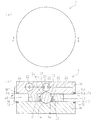
本発明の第1の実施形態例に係る振動発生装置1を図1ないし図3を用いて説明する。
本例の振動発生装置1は、マッサージ装置に用いられ、被振動体である人体(例えば、足裏P)に振動を与えるものである。特に、足裏Pが振動発生装置1に載置されると、足裏Pが振動によりマッサージされるものである。
(First embodiment)
A
The
本例の振動発生装置1は、第1部材11と、第2部材16と、振動発生部材20と、傾動支持手段30と、弾性部材40を有する。
The vibration generating
第1部材11と第2部材16は、足裏Pが載置されるものである。第1部材11と第2部材16は、足裏Pが載置された際に若干変形する可撓性を有する絶縁樹脂で形成され、足裏Pより外形が大きい平板状の円板により形成されている。なお、第1部材11または第2部材16のどちらか一方が可撓性を有するものでもよい。
The
本例では、足裏Pが載置される第2部材16が、第1部材11の上側に所定の空隙を持って略平行に対面して配されており、振動発生装置1の全体形状が略平板状に形成されている。第1部材11と第2部材16の外周には、導電性を有する接点部12、17がそれぞれ設けられている。
In this example, the
具体的に、第1部材11の上面の外周全周にはリング状のプリント基板13が設けられており、このプリント基板13の上面には、接点部12となるリング状の導電パターン14が設けられている。この導電パターン14の上面は、第1部材11の上面と面一に形成されている。
この第1部材11の接点部12となる導電パターン14は、後述の振動発生部材20の一方の端子21に電源23を介してリード線24により電気的に接続されている。
Specifically, a ring-shaped printed
The
また、第2部材16の下面の外周には、3つの独立したプリント基板18A、18B、18Cがリング状に配されており、これらのプリント基板18A、18B、18Cの下面には、接点部17となる導電パターン19A、19B、19Cがそれぞれ設けられている。つまり、3つの独立した導電パターン19A、19B、19Cが第2部材16の下面に周方向に並べられており、これらの導電パターン19A、19B、19Cの下面は、第2部材16の下面と面一に形成されている。
In addition, three independent printed
そして、第2部材16の接点部17は、後述の振動発生部材20の他方の端子22にリード線24により電気的に接続されている。
具体的に、第2部材16の接点部となる導電パターン19Aは、他方の端子22にリード線24により電気的に接続されている。また、第2部材16の接点部となる導電パターン19Bは、他方の端子22に第1抵抗26を介してリード線24により電気的に接続されている。また、第2部材16の接点部となる導電パターン19Cは、他方の端子22に第1抵抗26より抵抗の大きい第2抵抗27を介してリード線24により電気的に接続されている。
The
Specifically, the
なお、本例では、第1部材11の上面にリング状の導電パターン14が設けられ、第2部材16の下面に3つの独立した導電パターン19A、19B、19Cがそれぞれ設けられているが、この配置を逆にして、第1部材11の上面に3つの独立した導電パターンがそれぞれ設けられ、第2部材16の下面にリング状の導電パターンが設けられる構成としてもよい。この場合、振動発生部材20と電源23は第2部材16に配される。
In this example, a ring-shaped
振動発生部材20は、振動を発生するものである。
本例の振動発生部材20は、不図示の偏芯ウエイトを装着する振動モータを備えている。この振動発生部材20は、第2部材16の内部に固着されており、発生する振動を第2部材16に伝えられる。また振動発生部材20は、一方と他方の端子21、22を有している。一方の端子21は、第1部材11の外周に設けられた接点部12に電気的に接続されている。他方の端子22は、第2部材16の外周に設けられた接点部19A、19B、19Cに電気的に接続されている。
The
The
電源23は、振動発生部材20に電力を供給するものであり、例えば、1次電池あるいは2次電池を有する。この電源23は、例えば、第2部材16の内部に固着されている。
The
傾動支持手段30は、第2部材16を第1部材11に対して360°いずれの方向にも傾動自在に支持するものである。
本例の傾動支持手段30は、第2部材16に一部が固定された非導電性の硬質の球体31と、第1部材11に固定されると共に球体31の他部が傾動自在に嵌合された収容筒部32を有する。
The tilt support means 30 supports the
The tilt support means 30 of this example is a non-conductive
具体的には、球体31の一部が第2部材16の下面に設けられた凹部16Aに接着剤により固定されており、第2部材16が傾動すると球体31も一体に傾動する。
第1部材11の上面には、球体の半径より小さい深さの凹部11Aが形成されており、球体31の他部が凹部11Aに配される。
また、収容筒部32は、上側に円形の上側開口部33と下側に円形の下側開口部34を有しており、下側開口部34が第1部材11の凹部11Aを覆った状態で第1部材11に不図示のネジにより固定されている。
下側開口部34は、球体31の直径より少し大きく形成されており、球体31が傾動できるようになっている。なお、球体31が傾動しやすいように、球体31と接する収容筒部32と第1部材11の凹部11Aには潤滑油が塗布されている。
上側開口部33はその内部直径が球体31の直径より小さく形成されており、収容筒部32の内部に嵌合された球体31は収容筒部32から上側へ抜けない構造となっている。つまり、第2部材16は第1部材11に対して傾動自在に配されると共に第2部材16は第1部材11から離れない構造となっている。
Specifically, a part of the
A
In addition, the
The
The
そして、足裏Pが第2部材16に載置されると、第2部材16は第1部材11に対して球体31を支点として傾動できる。つまり、第2部材16の外周のどの位置でも同じ操作力により、球体31の他部が第1部材11の凹部11Aに摺接しながら、第2部材16は第1部材11に対して360°いずれの方向にも傾動できる。さらに第2部材16が傾動すると、接点部17の角が、接点部12の上面と線接触する。
When the sole P is placed on the
なお、本例では、図1の第1部材11と第2部材16が上下反対に配置されて足裏Pが第1部材11に載置されても、第1部材11は、傾動支持手段30により第2部材16に対して傾動できる。
In this example, even if the
弾性部材40は、足裏Pが第2部材16に載置されて第2部材16が傾動支持手段30により傾動すると圧縮されて弾性変形すると共に、足裏Pが第2部材16から離れた際に、弾性部材40の復元力により、第2部材16と第1部材11を所定の空隙を持つ初期状態に戻すものである。この初期状態では、弾性部材40は弾性変形しておらず、第2部材16の接点部は第1部材11の接点部と接触していない状態となっている。
The
本例の弾性部材40は、リング状のクッション材により構成されている。
この弾性部材40は、第1部材11と第2部材16の間に配されている。具体的に、弾性部材40は、球体31の外側に配されると共に第1部材11の接点部12の内側に配されている。また、弾性部材40の厚みは球体31の直径より小さく形成されている。
そして、弾性部材40は、第2部材16が第1部材11に対して傾動しやすいように、第1部材11のみに固定されている。なお、弾性部材40は、第2部材16のみに固定されてもよい。
The
The
The
以上の構成を有する本例の振動発生装置1は、足裏Pが斜め横方向(例えば図2(b)の斜め上横方向)から第2部材16に載置された際、第2部材16は、第1部材11に対して傾動支持手段30によりある方向に傾動して、弾性部材40の一部が圧縮されて弾性変形し、第2部材16の接点部17が第1部材11の接点部12に接触する。すると、振動発生部材20が電源23と電気的に接続されて動作して、足裏Pに振動が加わる。その際、振動発生部材20は第2部材16の傾動方向に応じて異なる動作をする。
In the
具体的には、第2部材16がある方向に傾動した際、接点部17である導電パターン19Aが接点部12である導電パターン14に接触すると、振動発生部材20が電源23と電気的に直接接続されて動作する。
また、第2部材16が別のある方向に傾動した際、接点部17である導電パターン19Bが接点部12である導電パターン14に接触すると、振動発生部材20が第1抵抗26を介して電源と電気的に接続されて、第1抵抗26と分圧された直流電圧が振動発生部材20に加わり振動発生部材20が動作する。
また、第2部材16がさらに別のある方向に傾動した際、接点部17である導電パターン19Cが接点部12である導電パターン14に接触すると、振動発生部材20が第1抵抗26より抵抗の大きい第2抵抗27を介して電源と電気的に接続されて、第2抵抗27と分圧された直流電圧が振動発生部材20に加わり動発生部材が動作する。
そして、振動発生部材20で発生する振動量は、導電パターン19A、導電パターン19B、導電パターン19Cの順に小さくなる。
よって、第1部材11の接点部12と第2部材16の接点部17が接触すると、振動発生部材20には、導通した導電パターンに応じた直流電圧が印加されることにより、振動発生部材20は第2部材16の傾動方向に応じて異なる振動をする。
Specifically, when the
Further, when the
Further, when the
The amount of vibration generated by the
Therefore, when the
その後、足裏Pが第2部材16から離れると、弾性部材40の復元力により、第2部材16の接点部17が第1部材11の接点部12から離れて、振動発生部材20に電圧が加わらなくなり振動発生部材20は動作を止めて、第2部材16と第1部材11は初期状態に戻る。
Thereafter, when the sole P is separated from the
このように、本例の振動発生装置1は、第1部材11と、第1部材11と空隙を持って配置される第2部材16と、第2部材16を第1部材11に対して傾動自在に支持する傾動支持手段30と、第1部材11または第2部材16に固定された振動発生部材20とを備えている。
また、第1部材11または第2部材16が傾動して第1部材11の接点部12と第2部材16の接点部17が接触すると、振動発生部材20は第1部材11または第2部材16の傾動方向に応じて異なる振動をする。
As described above, the
Further, when the
よって、第1部材11または第2部材16がある方向に傾動されて接点部間が接触すると、振動発生部材20が動作すると共に、振動発生部材20の振動量が第1部材11または第2部材16の傾動方向に応じて変わり、さらに、接点部を設けた第1部材11と第2部材16自体が複数の電源スイッチの換わりとなるため、本例の振動発生装置は、簡単な構成でありながら装置の動作時に振動量を容易に変えることができる。
また、従来のような構成では、広範囲用凸部は軸線方向のみに移動するものであり、軸線方向に対して斜め上横方向から操作されると、広範囲用凸部は軸線下方に移動しにくく応答性が低下してしまい、用途が限られる可能性がある。
一方、本例では、第2部材16が斜め横方向から操作されて傾動した際、第2部材16の外周のどの位置でも同じ操作力により第2部材16の接点部17と第1部材11の接点部12が接触して振動発生部材20が動作するため、応答性を低下させることなく操作範囲を広げられる。
また、第1部材11と第2部材16の配置を図1において上下反対にして、第1部材11が斜め横方向から操作されて傾動した際、第1部材11は傾動支持手段30により第2部材16に対して傾動する。すると、第1部材11の接点部12と第2部材16の接点部17が接触して、第2部材16に固定された振動発生部材20が振動する。そして、この振動が第2部材16、傾動支持手段30、第1部材11へと伝わり、第1部材11に接した足裏Pに振動が伝わる。
このように、第1部材11が斜め横方向から操作されて傾動した際に、第1部材11の外周のどの位置でも同じ操作力により第1部材11の接点部と第2部材16の接点部が接触して振動発生部材20が動作するため、応答性を低下させることなく操作範囲を広げられる。
Therefore, when the
Further, in the conventional configuration, the wide-area convex portion moves only in the axial direction, and when operated from an obliquely upward and lateral direction with respect to the axial direction, the wide-area convex portion does not easily move downward in the axial line. There is a possibility that the responsiveness is lowered and the application is limited.
On the other hand, in this example, when the
Also, when the
As described above, when the
また、本例では、第1部材11の接点部12または第2部材16の接点部17は、複数の独立した導電パターン19A、19B、19Cを周方向に沿って形成されており、振動発生部材20には、導通した導電パターンに応じた直流電圧が印加される。そのため、振動発生部材20の振動量が第1部材11または第2部材16の傾動方向に応じて変わるものである。
In this example, the
また、本例では、第1部材11または第2部材16が可撓性を有しているため、第1部材11と第2部材16が硬質材質により形成されている場合に比べて、振動時における接点部間の不導通を低減できる。
Moreover, in this example, since the
なお、以上の説明では、振動発生部材20と電源23が第2部材16に固定されているが、第1部材11の接点部12と第2部材16の接点部17が接触した際に振動発生装置が動作する構成であれば、振動発生部材20と電源23は第2部材16ではなく第1部材11に固定されたものでもよい。
In the above description, the
(第2の実施形態例)
本発明の第2の実施形態例に係る振動発生装置の接点部を図4を用いて説明する。図4において、図1ないし図3中の符号と同一の符号は同等の部材を指しており、詳細な説明は省略する。
(Second Embodiment)
The contact part of the vibration generator according to the second embodiment of the present invention will be described with reference to FIG. 4, the same reference numerals as those in FIGS. 1 to 3 denote the same members, and detailed description thereof is omitted.
本例の振動発生装置は、第1の実施形態例の接点部17に防振部材50を付加したものである。
具体的には第2部材16の接点部17は、防振部材50であるゴムを介して第2部材16の下面の外周に設けられたものである。
そして、本例は、第1の実施形態例と同様の効果を有すると共に、振動時における接点部間の不導通をより低減できる。
なお、本例の防振部材は第2部材16の接点部に設けるのではなく第1部材11の接点部に設けた構成でもよい。
The vibration generator of this example is obtained by adding a
Specifically, the
And this example has the same effect as a 1st example of an embodiment, and can further reduce the electric conduction between contact parts at the time of vibration.
In addition, the structure provided in the contact part of the
(第3の実施形態例)
本発明の第3の実施形態例に係る振動発生装置の接点部を図5を用いて説明する。図5において、図1ないし図4中の符号と同一の符号は同等の部材を指しており、詳細な説明は省略する。
(Third embodiment)
The contact part of the vibration generator according to the third embodiment of the present invention will be described with reference to FIG. In FIG. 5, the same reference numerals as those in FIGS. 1 to 4 denote the same members, and a detailed description thereof will be omitted.
本例の振動発生装置は、第1の実施形態例に、第2部材16と第1部材11の磁気吸引手段を付加したのである。
本例の磁気吸引手段は、第2部材16に設けられたリング状の磁石61と、第1部材11に磁石61と対面して設けられると共に磁石61に吸引されるリング状の磁性体62を有するものである。
具体的に、磁石61は、第2部材16の接点部17の内側に配されると共に弾性部材40の外側に配された状態で、第2部材16の下面に埋め込まれている。また磁性体62は、第1部材11の接点部11Aの内側に配されると共に弾性部材40の外側に配された状態で、第1部材11の上面に埋め込まれている。
本例の磁気吸引手段による吸引力は、第2部材16により圧縮されて弾性変形した弾性部材40が元の自然な状態に戻る復元力より小さいものとなっている。
The vibration generator of this example is obtained by adding the magnetic attraction means of the
The magnetic attraction means of this example includes a ring-shaped magnet 61 provided on the
Specifically, the magnet 61 is embedded in the lower surface of the
The attraction force by the magnetic attraction means of this example is smaller than the restoring force at which the
そして、第2部材16が傾動して、第2部材16の接点部が第1部材11の接点部に接触すると、本例の磁気吸引手段は、第2部材16の接点部と第1部材11の接点部との接触圧を高めて接点部間の不導通をより低減する。
その後、足裏Pが第2部材16から離れると、弾性部材40の復元力により、第2部材16の接点部が第1部材11の接点部から離れて、振動発生部材20に電圧が加わらなくなり、振動発生部材20は動作を止めて、第2部材16と第1部材11は初期状態に戻る。
そして、本例は、第1の実施形態例と同様の効果を有すると共に、振動時における接点部間の不導通をより低減できる。
本例の磁気吸引手段は、上記の構成に限らず、第2部材16の傾動により第2部材16が第1部材11に磁気吸引される構成であれば別の構成でもよい。
When the
Thereafter, when the sole P is separated from the
And this example has the same effect as a 1st example of an embodiment, and can further reduce the electric conduction between contact parts at the time of vibration.
The magnetic attraction means of this example is not limited to the above configuration, but may be another configuration as long as the
(第4の実施形態例)
本発明の第4の実施形態例に係る振動発生装置の接点部を図6の電気結線図を用いて説明する。図6において、図1ないし図5中の符号と同一の符号は同等の部材を指しており、詳細な説明は省略する。
(Fourth embodiment)
The contact part of the vibration generator according to the fourth embodiment of the present invention will be described with reference to the electrical connection diagram of FIG. In FIG. 6, the same reference numerals as those in FIGS. 1 to 5 denote the same members, and a detailed description thereof will be omitted.
第1の実施形態例では、第2部材16の下面外周に、独立した導電パターン19A、19B、19Cが形成され、第1部材11の上面外周に、リング状の導電パターン14が形成されているが、本例では、第2部材16の下面外周に、C字状の導電性を有する抵抗パターン28が形成され、第1部材11の上面外周に、抵抗パターン28と対面するC字状の導電パターン29が形成されるものである。
In the first embodiment, independent
本例の場合、導電パターン29が設けられた第1部材11に振動発生部材20と電源23が配される。そして、振動発生部材20の一方の端子21は、C字状の導電パターン29に電源23を介してリード線24により接続される。また振動発生部材20の他方の端子22は、抵抗パターン28の一端とリード線24で接続される。
In the case of this example, the
そして、第2部材16がある方向に傾動されて、抵抗パターン28のある部分が導電パターン29に接すると、振動発生部材20が電源23と電気的に接続されて動作する。その際、振動発生部材20には、抵抗パターン28と分圧された直流電圧が印加されるため、振動発生部材20には第2部材16の傾動方向に応じた電圧が加わり、振動発生部材の振動量は第2部材の傾動方向に応じて変わる。
そして、本例は、第1の実施形態例と同様の効果を有する。
When the
This example has the same effect as the first embodiment.
なお、本例では、第2部材16の下面外周に、C字状の導電性を有する抵抗パターン28が形成され、第1部材11の上面外周に、抵抗パターン28と対面するC字状の導電パターン29が形成されているが、この配置を逆にして、第1部材11の上面外周に、C字状の導電性を有する抵抗パターンが形成され、第2部材16の下面外周に、その抵抗パターンと対面するC字状の導電パターンが形成される構成としてもよい。この場合、振動発生部材20と電源23は第1部材11に配される。
In this example, a C-shaped
(変形例1)
また、本発明の振動発生装置では、第1の実施形態例と異なる接点部を用いてもよい。
第1の実施形態例における第1部材11の接点部12と第2部材16の接点部17は、導電パターンにより形成されているが、導電性の軟質材質、例えば導電ゴムにより形成されてもよい。
そして、本例は、第1の実施形態例と同様の効果を有すると共に、振動時における接点部間の不導通をより低減できる。
(Modification 1)
In the vibration generator of the present invention, a contact portion different from that in the first embodiment may be used.
In the first embodiment, the
And this example has the same effect as a 1st example of an embodiment, and can further reduce the electric conduction between contact parts at the time of vibration.
(変形例2)
また、本発明の振動発生装置では、第1の実施形態例と異なる接点部を用いてもよい。
第1の実施形態例では、第2部材16が傾動した際、第2部材16の接点部17の角が接点部12の上面と線接触するが、本例の第2部材の接点部は、第2部材16の下面に対して外側に向かって上側に広がる傾斜面を有するものであり、第2部材16が傾動した際、第1部材11の接点部12の上面と面接触されるものである。
そして、本例は、第1の実施形態例と同様の効果を有すると共に、振動時における接点部間の不導通をより低減できる。
なお、本例の接点部は第2部材16ではなく第1部材11に設けられるように構成されてもよい。この場合、第1部材11の接点部は第1部材11の上面に対して外側に向かって下側に広がる傾斜面を有するものである。
(Modification 2)
In the vibration generator of the present invention, a contact portion different from that in the first embodiment may be used.
In the first embodiment, when the
And this example has the same effect as a 1st example of an embodiment, and can further reduce the electric conduction between contact parts at the time of vibration.
The contact portion of this example may be configured to be provided on the
なお、以上の説明では、平板状の第1部材11と第2部材16により振動発生装置の全体形状が略平板状に形成されているが、第1部材11と第2部材16が半球体により形成されて半球体の突部が外側に配されることで振動発生装置の全体形状が略球体に形成されたものでもよい。
In the above description, the overall shape of the vibration generating device is formed in a substantially flat plate shape by the flat plate-like
また、以上の説明では、傾動支持手段30は、第2部材16に一部が固定された球体と、第1部材11に固定されると共に球体の他部が傾動自在に嵌合された収容筒部を有しているが、傾動支持手段は、第1部材に一端が固定されると共に第2部材に他端が固定されたコイルバネでもよい。この場合、上述の弾性部材は第1部材あるいは第2部材に固定されないものである。
Further, in the above description, the tilting support means 30 includes a sphere partially fixed to the
また、以上の説明では、傾動支持手段30は、第2部材16に一部が固定された球体と、第1部材11に固定されると共に球体の他部が傾動自在に嵌合された収容筒部を有しているが、傾動支持手段は、第1部材11に一部が固定された球体と、第2部材16に固定されると共に球体の他部が傾動自在に嵌合された収容筒部を有するものでもよい。
Further, in the above description, the tilting support means 30 includes a sphere partially fixed to the
1 振動発生装置
11 第1部材
11A 凹部
12 接点部
13 プリント基板
14 導電パターン
16 第2部材
16A 凹部
17 接点部
18A プリント基板
18B プリント基板
18C プリント基板
19A 導電パターン
19B 導電パターン
19C 導電パターン
20 振動発生部材
21 一方の端子
22 他方の端子
23 電源
24 リード線
26 第1抵抗
27 第2抵抗
28 抵抗パターン
29 導電パターン
30 傾動支持手段
31 球体
32 収容筒部
33 上側開口部
34 下側開口部
40 弾性部材
50 防振部材
61 磁石
62 磁性体
P 足裏
DESCRIPTION OF
DESCRIPTION OF
19B conductive pattern
19C
Claims (6)
前記第1部材または前記第2部材が傾動して前記第1部材の接点部と前記第2部材の接点部が接触すると、前記振動発生部材は前記第1部材または前記第2部材の傾動方向に応じて異なる動作をする、
ことを特徴とする振動発生装置。 A first member, a second member disposed with a gap with the first member, tilt support means for tiltably supporting the second member with respect to the first member, and the first member or the A vibration generating member fixed to the second member,
When the first member or the second member tilts and the contact portion of the first member contacts the contact portion of the second member, the vibration generating member moves in the tilt direction of the first member or the second member. Behave differently depending on
A vibration generator characterized by that.
前記振動発生部材には、導通した前記導電パターンに応じた直流電圧が印加される、
ことを特徴とする請求項1に記載の振動発生装置。 The contact portion of the first member or the contact portion of the second member is formed with a plurality of independent conductive patterns along the circumferential direction,
A direct current voltage corresponding to the conductive pattern that is conducted is applied to the vibration generating member.
The vibration generator according to claim 1.
前記振動発生部材には、前記抵抗パターンと分圧された直流電圧が印加される、
ことを特徴とする請求項1に記載の振動発生装置。 The contact portion of the first member or the contact portion of the second member is formed by a C-shaped resistance pattern,
The vibration generating member is applied with a DC voltage divided by the resistance pattern,
The vibration generator according to claim 1.
Priority Applications (2)
| Application Number | Priority Date | Filing Date | Title |
|---|---|---|---|
| JP2013248230A JP6190253B2 (en) | 2013-11-29 | 2013-11-29 | Vibration generator |
| US14/467,593 US20150155814A1 (en) | 2013-11-29 | 2014-08-25 | Vibration generating device |
Applications Claiming Priority (1)
| Application Number | Priority Date | Filing Date | Title |
|---|---|---|---|
| JP2013248230A JP6190253B2 (en) | 2013-11-29 | 2013-11-29 | Vibration generator |
Publications (3)
| Publication Number | Publication Date |
|---|---|
| JP2015104541A JP2015104541A (en) | 2015-06-08 |
| JP2015104541A5 JP2015104541A5 (en) | 2016-11-24 |
| JP6190253B2 true JP6190253B2 (en) | 2017-08-30 |
Family
ID=53266152
Family Applications (1)
| Application Number | Title | Priority Date | Filing Date |
|---|---|---|---|
| JP2013248230A Expired - Fee Related JP6190253B2 (en) | 2013-11-29 | 2013-11-29 | Vibration generator |
Country Status (2)
| Country | Link |
|---|---|
| US (1) | US20150155814A1 (en) |
| JP (1) | JP6190253B2 (en) |
Families Citing this family (1)
| Publication number | Priority date | Publication date | Assignee | Title |
|---|---|---|---|---|
| JP7092074B2 (en) * | 2019-03-08 | 2022-06-28 | 日本電信電話株式会社 | Vibration device |
Family Cites Families (16)
| Publication number | Priority date | Publication date | Assignee | Title |
|---|---|---|---|---|
| US4585977A (en) * | 1984-12-04 | 1986-04-29 | Dominic Arbisi | Electronic motor |
| SE504284C2 (en) * | 1994-06-03 | 1996-12-23 | Sem Ab | Adjusting means for adjusting an adjustable device, means for operating the adjusting means and use of the adjusting means |
| JPH09226431A (en) * | 1996-02-26 | 1997-09-02 | Nissan Diesel Motor Co Ltd | Vehicular footrest device |
| JP3752928B2 (en) * | 1999-10-05 | 2006-03-08 | ユーズ株式会社 | Motor and vibrator with variable resistor |
| JP2003325627A (en) * | 2002-05-17 | 2003-11-18 | Matsushita Electric Works Ltd | Vibration magnitude change-over mechanism for massager |
| US6830125B1 (en) * | 2002-11-04 | 2004-12-14 | F. Peter Bizlewicz | Vibratory energy dissipation and isolation with magnetically biased rolling members |
| US6822779B2 (en) * | 2002-11-13 | 2004-11-23 | Np Photonics Inc. | Method of finding drive values for an actuation mechanism |
| US7859167B2 (en) * | 2004-03-08 | 2010-12-28 | Panasonic Corporation | Micro actuator having tilt and vertical displacement and device having such micro actuator |
| CA2583107C (en) * | 2006-03-31 | 2011-09-13 | Universite De Sherbrooke | High performance differential actuator for robotic interaction tasks |
| US7598688B2 (en) * | 2006-06-22 | 2009-10-06 | Orbotech Ltd | Tilting device |
| US7880410B2 (en) * | 2007-03-21 | 2011-02-01 | Saia-Burgess, Inc. | Rotary, limited rotation bi-directional, direct current actuator |
| EP2017949A1 (en) * | 2007-07-16 | 2009-01-21 | Interuniversitair Microelektronica Centrum (IMEC) | Stepping actuator and method of fabrication |
| US8044629B2 (en) * | 2008-08-29 | 2011-10-25 | Northern Illinois University | Self-tuning vibration absorber |
| JP5277010B2 (en) * | 2009-02-09 | 2013-08-28 | パナソニック株式会社 | Drive device |
| US8395877B2 (en) * | 2009-02-12 | 2013-03-12 | International Business Machines Corporation | High-speed electrostatic actuation of MEMS-based devices |
| KR20110117534A (en) * | 2010-04-21 | 2011-10-27 | 삼성전자주식회사 | Vibration control device and method |
-
2013
- 2013-11-29 JP JP2013248230A patent/JP6190253B2/en not_active Expired - Fee Related
-
2014
- 2014-08-25 US US14/467,593 patent/US20150155814A1/en not_active Abandoned
Also Published As
| Publication number | Publication date |
|---|---|
| JP2015104541A (en) | 2015-06-08 |
| US20150155814A1 (en) | 2015-06-04 |
Similar Documents
| Publication | Publication Date | Title |
|---|---|---|
| US9048718B2 (en) | Linear vibrator having pole plate positioned in weight thereof | |
| CN108124027B (en) | Electronic device | |
| US20120187780A1 (en) | Apparatus for generating vibrations | |
| US20120169148A1 (en) | Linear vibration motor | |
| US8803373B2 (en) | Linear vibration motor | |
| US20170341108A1 (en) | Linear vibration motor | |
| KR101378891B1 (en) | Touch motion switch | |
| CN107847975A (en) | Linear vibration motor and the mobile electronic device including the linear vibration motor | |
| CN113541432B (en) | Actuator for generating vibrations | |
| TW201145770A (en) | Electromechanical transducer with dielectric elastomer | |
| JP2022173461A (en) | Vibration generating device and electronic apparatus | |
| JP2018088752A (en) | Vibration generating device and electronic apparatus | |
| JP6190253B2 (en) | Vibration generator | |
| KR20120059131A (en) | Apparatus for generating vibration | |
| US10263501B2 (en) | Vibration generator and electronic device having the same | |
| JP2006100084A (en) | Multi-direction operating device | |
| KR100650905B1 (en) | Vibrator and mobile communication terminal with vibrator | |
| KR20120064808A (en) | Linear vibration | |
| KR20120006729A (en) | Haptic feed-back device of mobile phone | |
| KR20120059132A (en) | Apparatus for generating vibration | |
| CN113131707A (en) | Vibration actuator and electronic device | |
| JP2019134509A (en) | Vibration motor | |
| JP6950645B2 (en) | Electronics | |
| JP7470652B2 (en) | Push button switch parts | |
| KR102495107B1 (en) | Apparatus of generating surface texture using hydraulic electrostatic force actuator and pin |
Legal Events
| Date | Code | Title | Description |
|---|---|---|---|
| A521 | Request for written amendment filed |
Free format text: JAPANESE INTERMEDIATE CODE: A523 Effective date: 20161011 |
|
| A621 | Written request for application examination |
Free format text: JAPANESE INTERMEDIATE CODE: A621 Effective date: 20161011 |
|
| A977 | Report on retrieval |
Free format text: JAPANESE INTERMEDIATE CODE: A971007 Effective date: 20170714 |
|
| TRDD | Decision of grant or rejection written | ||
| A01 | Written decision to grant a patent or to grant a registration (utility model) |
Free format text: JAPANESE INTERMEDIATE CODE: A01 Effective date: 20170724 |
|
| A61 | First payment of annual fees (during grant procedure) |
Free format text: JAPANESE INTERMEDIATE CODE: A61 Effective date: 20170804 |
|
| R150 | Certificate of patent or registration of utility model |
Ref document number: 6190253 Country of ref document: JP Free format text: JAPANESE INTERMEDIATE CODE: R150 |
|
| R250 | Receipt of annual fees |
Free format text: JAPANESE INTERMEDIATE CODE: R250 |
|
| LAPS | Cancellation because of no payment of annual fees |