KR20120006729A - Haptic feed-back device of mobile phone - Google Patents
Haptic feed-back device of mobile phone Download PDFInfo
- Publication number
- KR20120006729A KR20120006729A KR1020100067362A KR20100067362A KR20120006729A KR 20120006729 A KR20120006729 A KR 20120006729A KR 1020100067362 A KR1020100067362 A KR 1020100067362A KR 20100067362 A KR20100067362 A KR 20100067362A KR 20120006729 A KR20120006729 A KR 20120006729A
- Authority
- KR
- South Korea
- Prior art keywords
- actuator
- touch screen
- ball
- side wall
- screen panel
- Prior art date
Links
- 238000000034 method Methods 0.000 claims description 10
- 230000000694 effects Effects 0.000 abstract description 4
- 230000035807 sensation Effects 0.000 abstract description 3
- 239000004973 liquid crystal related substance Substances 0.000 abstract 1
- 238000010586 diagram Methods 0.000 description 3
- 230000008859 change Effects 0.000 description 2
- 239000000463 material Substances 0.000 description 2
- 239000000843 powder Substances 0.000 description 2
- 230000004044 response Effects 0.000 description 2
- 230000004043 responsiveness Effects 0.000 description 2
- 230000015541 sensory perception of touch Effects 0.000 description 2
- 230000009471 action Effects 0.000 description 1
- 239000000919 ceramic Substances 0.000 description 1
- 230000006870 function Effects 0.000 description 1
- 238000012986 modification Methods 0.000 description 1
- 230000004048 modification Effects 0.000 description 1
Images


Classifications
-
- G—PHYSICS
- G06—COMPUTING; CALCULATING OR COUNTING
- G06F—ELECTRIC DIGITAL DATA PROCESSING
- G06F3/00—Input arrangements for transferring data to be processed into a form capable of being handled by the computer; Output arrangements for transferring data from processing unit to output unit, e.g. interface arrangements
- G06F3/01—Input arrangements or combined input and output arrangements for interaction between user and computer
- G06F3/016—Input arrangements with force or tactile feedback as computer generated output to the user
-
- B—PERFORMING OPERATIONS; TRANSPORTING
- B06—GENERATING OR TRANSMITTING MECHANICAL VIBRATIONS IN GENERAL
- B06B—METHODS OR APPARATUS FOR GENERATING OR TRANSMITTING MECHANICAL VIBRATIONS OF INFRASONIC, SONIC, OR ULTRASONIC FREQUENCY, e.g. FOR PERFORMING MECHANICAL WORK IN GENERAL
- B06B1/00—Methods or apparatus for generating mechanical vibrations of infrasonic, sonic, or ultrasonic frequency
- B06B1/02—Methods or apparatus for generating mechanical vibrations of infrasonic, sonic, or ultrasonic frequency making use of electrical energy
- B06B1/06—Methods or apparatus for generating mechanical vibrations of infrasonic, sonic, or ultrasonic frequency making use of electrical energy operating with piezoelectric effect or with electrostriction
-
- G—PHYSICS
- G06—COMPUTING; CALCULATING OR COUNTING
- G06F—ELECTRIC DIGITAL DATA PROCESSING
- G06F1/00—Details not covered by groups G06F3/00 - G06F13/00 and G06F21/00
- G06F1/16—Constructional details or arrangements
- G06F1/1613—Constructional details or arrangements for portable computers
- G06F1/1626—Constructional details or arrangements for portable computers with a single-body enclosure integrating a flat display, e.g. Personal Digital Assistants [PDAs]
-
- G—PHYSICS
- G06—COMPUTING; CALCULATING OR COUNTING
- G06F—ELECTRIC DIGITAL DATA PROCESSING
- G06F1/00—Details not covered by groups G06F3/00 - G06F13/00 and G06F21/00
- G06F1/16—Constructional details or arrangements
- G06F1/1613—Constructional details or arrangements for portable computers
- G06F1/1633—Constructional details or arrangements of portable computers not specific to the type of enclosures covered by groups G06F1/1615 - G06F1/1626
- G06F1/1637—Details related to the display arrangement, including those related to the mounting of the display in the housing
- G06F1/1643—Details related to the display arrangement, including those related to the mounting of the display in the housing the display being associated to a digitizer, e.g. laptops that can be used as penpads
-
- G—PHYSICS
- G06—COMPUTING; CALCULATING OR COUNTING
- G06F—ELECTRIC DIGITAL DATA PROCESSING
- G06F1/00—Details not covered by groups G06F3/00 - G06F13/00 and G06F21/00
- G06F1/16—Constructional details or arrangements
- G06F1/1613—Constructional details or arrangements for portable computers
- G06F1/1633—Constructional details or arrangements of portable computers not specific to the type of enclosures covered by groups G06F1/1615 - G06F1/1626
- G06F1/1684—Constructional details or arrangements related to integrated I/O peripherals not covered by groups G06F1/1635 - G06F1/1675
-
- H—ELECTRICITY
- H02—GENERATION; CONVERSION OR DISTRIBUTION OF ELECTRIC POWER
- H02N—ELECTRIC MACHINES NOT OTHERWISE PROVIDED FOR
- H02N2/00—Electric machines in general using piezoelectric effect, electrostriction or magnetostriction
- H02N2/02—Electric machines in general using piezoelectric effect, electrostriction or magnetostriction producing linear motion, e.g. actuators; Linear positioners ; Linear motors
Abstract
Description
본 발명은 휴대폰 진동용 진동발생장치에 관한 것이다.The present invention relates to a vibration generating device for mobile phone vibration.
휴대전화, 게임기, 휴대 정보 단말기 등 휴대용 전자기기에 있어 타인에게 외부 음향에 의한 피해를 방지하기 위해 다양한 형태의 진동 발생 장치가 휴대용 전자기기에 장착되고 있다. 특히, 이러한 진동 발생 장치는 휴대전화에 탑재되어 무음의 착신신호 발생장치로 이용되는데, 최근 휴대전화의 소형화, 슬림화되는 추세에서 그에 장착되는 진동 발생 장치 또한 소형화, 고기능화를 요구하고 있다.In portable electronic devices such as mobile phones, game consoles and portable information terminals, various types of vibration generating devices are installed in portable electronic devices to prevent damages caused by external sound to others. In particular, such a vibration generating device is mounted on a mobile phone and used as a silent incoming signal generating device. Recently, in the trend of miniaturization and slimming of the mobile phone, the vibration generating device mounted thereon also requires miniaturization and high functionality.
현재 휴대전화와 같이 통신기기에 적용되고 있는 착신수단 중 하나인 터치 패널은 조작 편의성이 보장되기는 하나, 접촉에 의한 입력 후 피드백되는 촉감이 없기 때문에 사용자의 흥미가 쉽게 반감되며, 입력이 제대로 이루어졌는지 확인이 종종 어렵다는 단점이 있다. 일례로 접촉(터치) 시 화면의 전환 및/또는 사운드를 발생시키는 방법이 있지만, 어두운 곳이나 소음이 심한 곳에서는 인지하기가 어렵게 된다. 이를 위한 대안으로, 접촉 시 진동을 발생시키는 터치 패널이 채용된 휴대폰 등이 최근 시판되고 있다. 진동에 의한 피드백은 사용자가 신체 접촉으로 인지하는 것이므로, 그 효과가 우수하다.Touch panel, which is one of the receiving means that is applied to communication devices such as mobile phones, is guaranteed operation convenience, but user's interest is easily halved because there is no feedback feeling after input by touch. The disadvantage is that it is often difficult to identify. For example, there is a method of switching the screen and / or generating a sound when touched (touched), but it is difficult to recognize in a dark place or a noisy place. As an alternative to this, mobile phones and the like employing a touch panel for generating vibrations upon contact have recently been commercially available. Since the feedback by the vibration is perceived by the user as the body contact, the effect is excellent.
이러한 진동을 발생시키는 진동발생장치는 전자기적 힘의 발생원리를 이용하여 전기적 에너지를 기계적 진동으로 변환하는 부품으로써 휴대전화에 탑재되어 무음 착신 알림용으로 사용되고 있다. 종래 기술에 따른 진동발생장치는 편심을 갖는 중량체를 갖는 회전자를 회전시켜 기계적 진동을 얻는 방식을 사용하고 있으며, 회전력은 브러쉬와 정류자의 접점을 통하여 정류작용을 거쳐 회전자의 코일에 전류를 공급하는 구조로 발생시킨다.Vibration generating device for generating such vibration is a component for converting electrical energy into mechanical vibration by using the principle of electromagnetic force is mounted on the mobile phone is used for notification of silent reception. The vibration generating apparatus according to the prior art uses a method of obtaining a mechanical vibration by rotating the rotor having a weight having an eccentric body, the rotational force is applied to the coil of the rotor through the rectifying action through the contact of the brush and the commutator It is generated in a supply structure.
그러나, 종래 기술에 따른 진동발생장치는 브러쉬가 정류자의 세그먼트(segment)와 세그먼트 사이의 극간을 지나면서 기계적인 마찰과 전기적인 스파크(spark)를 유발시키고, 이로 인해 블랙파우더(black powder)와 같은 이 물질을 생성하여 진동발생장치의 수명을 단축시키는 문제점이 있다.However, the vibration generating device according to the prior art causes the mechanical friction and the electrical spark as the brush passes between the segment of the commutator and the segment between the segments, which causes a black powder such as black powder. There is a problem of generating this material to shorten the life of the vibration generating device.
이에 안정적인 선형진동을 확보하기 위한 장치로 도 1에 도시된 구조의 진동발생장치가 제안되었다.As a device for securing a stable linear vibration has been proposed a vibration generating device of the structure shown in FIG.
종래의 진동발생장치는 도시된 것과 같이, 전류를 인가하여 자기장을 유도하는 코일(11)을 포함하는 고정자(12), 일면이 코일(11)에 대향하는 마그넷(13)을 포함하는 진동자(14), 고정자(12)에 결합되며 진동자(14)가 선형 운동하도록 탄성지지하는 스프링부재와, 진동자(14)의 선형 운동에 따른 고정자(12)와의 접촉을 방지하는 댐퍼(18) 및 진동자(14)의 선형 운동을 가이드 하는 가이드부(20)을 구성요소로 하여 안정적으로 선형의 진동을 얻을 수 있고, 진동자(14)의 과다한 진동으로 인해 진동자(14)가 고정자(12)에 충격을 가할 경우 발생하는 터치음을 방지할 수 있으며, 외부 충격 시 진동자(14)의 좌우진동을 방지할 수 있도록 하는 구성이다.Conventional vibration generating device is a
그러나, 이러한 자석을 이용한 리니어 진동모터는 응답속도가 느려 순간적인 작동제어가 불가능하며, 조작감이 떨어지는 문제가 있다.However, the linear vibration motor using such a magnet has a slow response speed and thus, instantaneous operation control is not possible, resulting in a poor operation feeling.
본 발명은 상술한 문제를 해결하기 위하여 안출된 것으로, 본 발명의 목적은 터치스크린패널의 이동성을 확대하는 패널이동모듈을 구비하며, 이러한 이동성을 압전소자와 탄성체로 구현되는 액츄에이터를 이용하여 다양한 움직임에 대한 빠른 피드백을 받을 수 있는 장치를 구현하여 종래의 자석 리니어 모터보다 현저하게 향상되는 응답성을 구현하여 실시간 촉각 구현이 가능하며, 다양한 느낌을 실시간으로 제공할 수 있는 휴대 단말기 촉각 피드백 장치를 제공하는 데 있다.The present invention has been made to solve the above-described problem, an object of the present invention is to include a panel moving module for expanding the mobility of the touch screen panel, the movement of the various movements using an actuator implemented by a piezoelectric element and an elastic body Implementing a device that can receive fast feedback on the device enables real-time tactile realization by implementing responsiveness that is remarkably improved than conventional magnetic linear motors, and provides a mobile terminal tactile feedback device that can provide various feelings in real time. There is.
상술한 과제를 해결하기 위한 수단으로서, 본 발명은 엘시디 모듈을 수용하는 내부공간과, 측벽 프레임을 구비하는 하우징모듈; 상기 측벽프레임 상에 배치되는 터치스크린 패널; 상기 하우징모듈의 전면에 배치되어, 상기 터치스크린 패널과 접하는 액츄에이터;를 포함하는 휴대 단말기 촉각 피드백 장치를 제공할 수 있다.As a means for solving the above problems, the present invention provides an internal space for accommodating an LCD module, and a housing module having a side wall frame; A touch screen panel disposed on the sidewall frame; It is possible to provide a portable terminal haptic feedback device comprising a; disposed on the front of the housing module, the actuator in contact with the touch screen panel.
이 경우 상기 액츄에이터는, 상기 측벽 프레임의 전면에 고정되며, 탄성플레이트 상에 배치되는 압전소자를 포함하여 구성될 수 있다.In this case, the actuator may be fixed to the front surface of the side wall frame, and may include a piezoelectric element disposed on the elastic plate.
특히, 상기 액츄에이터는, 탄성플레이트의 상하면에 부착되는 압전소자를 구비하되, 상기 압전소자를 상기 탄성플레이트 보다 작은 길이를 구비하여 상기 탄성블레이트의 양 말단부가 외부로 노출되는 구조로 형성될 수 있다.In particular, the actuator may include a piezoelectric element attached to upper and lower surfaces of the elastic plate, and the piezoelectric element may have a length smaller than that of the elastic plate so that both ends of the elastic blade are exposed to the outside. .
상술한 본 발명에 따른 상기 측벽 프레임은, 상기 측벽 프레임의 상부면에 돌출형 구조로 형성되며, 내부에는 볼(Ball) 수용부를 구비하는 패널이동모듈을 더 구비하여 구성될 수 있다.The side wall frame according to the present invention is formed in a protruding structure on the upper surface of the side wall frame, it may be configured to further include a panel moving module having a ball receiving portion therein.
특히, 상기 패널이동모듈은, 상기 볼 수용부의 높이가 수용되는 볼의 높이 이하로 형성되며, 상기 볼은 상기 터치스크린 패널의 측변부와 접촉하도록 구현될 수 있다.In particular, the panel moving module is formed to be less than the height of the ball is accommodated in the height of the ball receiving portion, the ball may be implemented to contact the side of the touch screen panel.
이 경우 상기 터치스크린 패널의 측변부에는, 상기 패널이동모듈과 대응되는 위치에 상기 볼의 상측 일부를 수용하는 제2볼수용부를 더 구비할 수 있다.In this case, the side portion of the touch screen panel, may further include a second ball receiving portion for receiving a portion of the upper side of the ball at a position corresponding to the panel moving module.
또한, 상기 액츄에이터는 구동을 위한 Driver IC와 연결될 수 있다.
In addition, the actuator may be connected to a driver IC for driving.
본 발명에 따르면, 터치스크린패널의 이동성을 확대하는 패널이동모듈을 구비하며, 이러한 이동성을 압전소자와 탄성체로 구현되는 액츄에이터를 이용하여 다양한 움직임에 대한 빠른 피드백을 받을 수 있는 장치를 구현하여 종래의 자석 리니어 모터보다 현저하게 향상되는 응답성을 구현하여 실시간 촉각 구현이 가능하며, 다양한 느낌을 실시간으로 제공할 수 있는 효과가 있다.According to the present invention, there is provided a panel moving module that expands the mobility of the touch screen panel, and implements a device capable of receiving fast feedback on various movements by using an actuator implemented with a piezoelectric element and an elastic body. Responsiveness is significantly improved than that of a magnetic linear motor, enabling real-time tactile realization and providing various feelings in real time.
도 1은 종래의 휴대폰 진동용 선형 진동발생장치의 요부를 도시한 개념도이다.
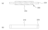
도 2a는 본 발명에 따른 일 실시예를 도시한 개념도이며, 도 2b는 본 발명에 따른 액츄에이터의 구조를 도시한 개념도이다.
도 3은 본 발명에 따른 휴대 단말기 촉각 피드백 장치의 측면도 및 평면도를 도시한 것이다.1 is a conceptual diagram showing the main portion of a conventional linear vibration generating device for mobile phone vibration.
Figure 2a is a conceptual diagram showing an embodiment according to the present invention, Figure 2b is a conceptual diagram showing the structure of the actuator according to the present invention.
3 is a side view and a plan view of a portable terminal tactile feedback device according to the present invention.
이하에서는 첨부한 도면을 참조하여 본 발명에 따른 구성 및 작용을 구체적으로 설명한다. 첨부 도면을 참조하여 설명함에 있어, 도면 부호에 관계없이 동일한 구성요소는 동일한 참조부여를 부여하고, 이에 대한 중복설명은 생략하기로 한다. 제1, 제2 등의 용어는 다양한 구성요소들을 설명하는데 사용될 수 있지만, 상기 구성요소들은 상기 용어들에 의해 한정되어서는 안 된다. 상기 용어들은 하나의 구성요소를 다른 구성요소로부터 구별하는 목적으로만 사용된다.Hereinafter, with reference to the accompanying drawings will be described in detail the configuration and operation according to the present invention. In the description with reference to the accompanying drawings, the same components are given the same reference numerals regardless of the reference numerals, and duplicate description thereof will be omitted. The terms first, second, etc. may be used to describe various components, but the components should not be limited by the terms. The terms are used only for the purpose of distinguishing one component from another.
도 2a를 참조하면, 본 발명에 따른 휴대 단말기 촉각 피드백 장치는 엘시디 모듈을 수용하는 내부공간(S)과, 측벽 프레임(110)을 구비하는 하우징모듈(100)과 상기 측벽프레임(110) 상에 배치되는 터치스크린 패널(200), 그리고 상기 하우징모듈의 전면에 배치되어, 상기 터치스크린 패널과 접하는 액츄에이터(300)을 포함하여 구성된다.Referring to FIG. 2A, the mobile terminal tactile feedback device according to the present invention includes an internal space S for accommodating an LCD module, a
상기 하우징 모듈(100)은 도시된 구조와 같이, 하부 플레이트(140)상에 측벽 프레임(110)을 포함하며, 내부가 비어 있는 내부공간(S)를 구비하는 구조로 형성되며, 상기 내부공간(S)에는 LCD 모듈이 배치되며, 상기 측벽프레임(110)의 상면에는 터치스크린패널(200)이 장착되게 된다.The
특히, 상기 측벽프레임(110)의 상면에는 상기 터치스크린패널(200)과의 접촉면에 볼(130)을 배치하여 상기 터치스크린패널(200)의 미세한 수평 이동 또는 상하 이동시 접촉 저항을 줄일 수 있도록 한다. 여기서 수평이동이란 터치스크린 패널의 정지상태에서 직교좌표를 가상할 경우 X축방향 또는 Y축방향으로의 움직임을 의미한다.In particular, the
이 경우 상기 볼(130)의 배치는 상기 측벽프레임의 상면에 형성되는 패널이동모듈을 구비하되, 상기 패널이동모듈은 볼 수용부(120)과 볼(130)을 포함하여 구성된다. 즉 상기 측벽프레임의 상면에 볼 수용부(120)를 마련하되 상기 볼수용부(120)의 내부에 오목한 홈을 형성하고, 그 내부에 볼을 배치하는 구조로 구현할 수 있다. 즉, 상기 볼 수용부는 측벽프레임 상에 우물구조로 된 구조물을 형성하여 구현하거나, 도시된 구조처럼, 상기 측벽프레임(110)의 상부면에 형성되는 구조물과 상기 터치스크린패널의 하부면에 형성되는 구조물(제2볼수용부)이 맞물려서 볼을 수용하는 구조로 형성하는 것도 가능하다. 이 경우 상기 볼의 상부면이 상기 터치스크린 패널의 하부면과 접촉을 하여야 하는바, 상기 측벽프레임의 상부면에 형성되는 볼수용부의 높이는 상기 볼의 높이보다 낮게 형성함이 더욱 바람직하다.In this case, the arrangement of the
상기 액츄에이터(300)는 탄성플레이트에 압전소자를 형성하는 구조로 형성되며, 압전소자는 전기적 에너지가 기계적 에너지로 또는 기계적 에너지가 전기적에너지로 변환될 수 있는 소재로서, 압전효과(Piezoelectric Effect)의 구현이 가능한 세라믹스가 사용될 수 있다.The
상기 액츄에이터(300)는 도 2b에 도시된 것과 같이, (a) 액츄에이터의 측면부를 통해 설명하면, 중앙부에 탄성플레이트(320)가 배치되고, 그 상부 및 하부면에 압전체(310)이 부착되는 구조로 형성되며, 특히 상기 압전체(310)의 길이가 상기 탄성플레이트(320)의 길이보다 작게 형성됨이 바람직하다. (b) 따라서 상기 액츄에이터의 평면은 중앙부에 압전체(310)이 형성되고, 상기 압전체의 말단 부위에 탄성플레이트(320)이 노출되는 구조로 형성된다. 상기 탄성플레이트(320)의 노출면은 상기 하우징모듈의 전면에 배치되어, 상기 터치스크린 패널과 접하는 구조로 배치된다. As shown in FIG. 2B, the
즉, 상기 탄성플레이트(320)의 노출부분이 도 2a의 하우징 모듈의 측벽프레임의 전면에 부착되는 구조로 형성하며, 상기 압전체의 상부면이 상기 터치스크린패널에 접촉되는 구조로 배치되게 된다.That is, the exposed portion of the
도 3은 본 발명에 다른 하우징모듈과 액츄에이터, 터치스크린패널의 결합된 상태의 측면도 및 평면도를 도시한 것이다.Figure 3 shows a side view and a plan view of a combined state of the housing module, the actuator, the touch screen panel according to the present invention.
이와 같은 구성에서의 구동방식은 외부에서 터치스크린패널(200)에 가해지는 신호를 감지하여 액츄에이터(300)에 전달되게 되면, 상기 액츄에이터는 이 신호를 기계적 에너지로 변환하여 상기 터치패널스크린을 좌우로 움직이게 되며, 이를 통해 촉각을 형성하게 된다. 이 경우 상기 터치패널스크린(200)의 움직임은 측벽프레임(110)의 상부에 배치되는 볼(130)의 존재로 인해 보다 용이하게 움직임을 확보할 수 있게 된다. 즉 상기 액츄에이터가 입력되는 신호의 주파수와 진폭에 따라 다양한 움직임을 구현하게 되어 상기 터치패널스크린(200)에는 다양한 촉감을 피드백 받을 수 있게 된다.In this configuration, the driving method senses a signal applied to the
아래의 표 1은 본 발명에 따른 촉각 피드백 장치를 이용하여 입력되는 신호의 전압과 주파수의 변화에 따른 손끝 촉감을 측정한 결과를 도시한 것이다.Table 1 below shows the results of measuring the fingertips according to the change in voltage and frequency of the input signal using the tactile feedback device according to the present invention.
{표 1}{Table 1}

상기의 {표 1}을 참조하여 보면, 이는 구동소자(본 실시예에서는, Function Gnenrator를 이용함)를 이용하여 전압과 주파수 변화에 따른 손감 촉각을 나타낸 결과로, 200Hz에서 10V 이상의 입력전압에서 가장 강한 촉감을 느낄 수 있게 됨을 알 수 있다.Referring to {Table 1} above, this is a result of the sense of tactile sensation according to the change of voltage and frequency by using a driving element (in this embodiment, using a function generator). You can see that you can feel the touch.
즉, 본 발명에 따른 촉각 피드백 장치는 종래의 선형 진동발생장치와는 전혀 상이한 구성의 압전소자를 이용한 액츄에이터와 이를 장착하기 위한 하우징모듈의 구조를 이용하여 종래의 밋밋한 촉각과는 다른 생동감 있는 촉각을 제공함과 동시에, 종래의 자석을 이용한 리니어 진동모터에 비해 빠른 응답속도와 순간적인 작동제어를 구현할 수 있게 된다.That is, the tactile feedback device according to the present invention uses an actuator using a piezoelectric element that is completely different from the conventional linear vibration generating device, and uses a structure of a housing module for mounting the same to provide a lively tactile sensation different from the conventional flat tactile sense. At the same time, it is possible to realize a faster response speed and instantaneous operation control than a conventional linear vibration motor using a magnet.
전술한 바와 같은 본 발명의 상세한 설명에서는 구체적인 실시예에 관해 설명하였다. 그러나 본 발명의 범주에서 벗어나지 않는 한도 내에서는 여러 가지 변형이 가능하다. 본 발명의 기술적 사상은 본 발명의 기술한 실시예에 국한되어 정해져서는 안 되며, 특허청구범위뿐만 아니라 이 특허청구범위와 균등한 것들에 의해 정해져야 한다. In the foregoing detailed description of the present invention, specific examples have been described. However, various modifications are possible within the scope of the present invention. The technical idea of the present invention should not be limited to the embodiments of the present invention but should be determined by the equivalents of the claims and the claims.
100: 하우징모듈
110: 액츄에이터
120: 볼 수용부
130: 볼
140: 하부 플레이트
200: 터치스크린패널
300: 액츄에이터
310: 탄성플레이트
320: 압전체100: housing module
110: actuator
120: ball receiving portion
130: ball
140: lower plate
200: touch screen panel
300: actuator
310: elastic plate
320: piezoelectric
Claims (8)
상기 측벽프레임 상에 배치되는 터치스크린 패널;
상기 하우징모듈의 전면에 배치되어, 상기 터치스크린 패널과 접하는 액츄에이터;
를 포함하는 휴대 단말기 촉각 피드백 장치.
An internal space accommodating the LCD module and a housing module having a side wall frame;
A touch screen panel disposed on the sidewall frame;
An actuator disposed on a front surface of the housing module and in contact with the touch screen panel;
A mobile terminal tactile feedback device comprising a.
상기 액츄에이터는,
상기 측벽 프레임의 전면에 고정되며, 탄성플레이트 상에 배치되는 압전소자를 포함하여 구성되는 휴대 단말기 촉각 피드백 장치.
The method according to claim 1,
The actuator is
The mobile terminal tactile feedback device is fixed to the front surface of the side wall frame and comprises a piezoelectric element disposed on the elastic plate.
상기 액츄에이터는,
탄성플레이트의 상하면에 부착되는 압전소자를 구비하되,
상기 압전소자를 상기 탄성플레이트 보다 작은 길이를 구비하여 상기 탄성블레이트의 양 말단부가 외부로 노출되는 구조로 형성되는 휴대 단말기 촉각 피드백 장치.
The method according to claim 2,
The actuator is
It is provided with a piezoelectric element attached to the upper and lower surfaces of the elastic plate,
And a piezoelectric element having a length smaller than that of the elastic plate so that both ends of the elastic blade are exposed to the outside.
상기 측벽 프레임은,
상기 측벽 프레임의 상부면에 돌출형 구조로 형성되며, 내부에는 볼(Ball) 수용부를 구비하는 패널이동모듈을 더 구비하는 휴대 단말기 촉각 피드백 장치.
The method according to claim 3,
The side wall frame,
The mobile terminal tactile feedback device further comprising a panel moving module having a protruding structure on an upper surface of the side wall frame and having a ball receiving portion therein.
상기 패널이동모듈은,
상기 볼 수용부의 높이가 수용되는 볼의 높이 이하로 형성되는 휴대단말기 촉각 피드백 장치.
The method of claim 4,
The panel moving module,
A portable terminal haptic feedback device formed below the height of the ball is accommodated in the height of the ball receiving portion.
상기 볼은 상기 터치스크린 패널의 측변부와 접촉하는 휴대단말기 촉각 피드백 장치.
The method of claim 4,
And the ball is in contact with the side portion of the touch screen panel.
상기 터치스크린 패널의 측변부에는,
상기 패널이동모듈과 대응되는 위치에 상기 볼의 상측 일부를 수용하는 제2볼수용부를 더 구비하는 휴대 단말기 촉각 피드백 장치.
The method of claim 4,
In the side portion of the touch screen panel,
And a second ball accommodating part accommodating an upper portion of the ball at a position corresponding to the panel moving module.
상기 액츄에이터는 구동을 위한 구동소자(Driver IC)와 연결되는 휴대 단말기 촉각 피드백 장치.
The method according to claim 7,
The actuator is a portable terminal tactile feedback device connected to a driver IC for driving.
Priority Applications (1)
| Application Number | Priority Date | Filing Date | Title |
|---|---|---|---|
| KR1020100067362A KR101664495B1 (en) | 2010-07-13 | 2010-07-13 | Haptic feed-back device of Mobile phone |
Applications Claiming Priority (1)
| Application Number | Priority Date | Filing Date | Title |
|---|---|---|---|
| KR1020100067362A KR101664495B1 (en) | 2010-07-13 | 2010-07-13 | Haptic feed-back device of Mobile phone |
Publications (2)
| Publication Number | Publication Date |
|---|---|
| KR20120006729A true KR20120006729A (en) | 2012-01-19 |
| KR101664495B1 KR101664495B1 (en) | 2016-10-10 |
Family
ID=45612322
Family Applications (1)
| Application Number | Title | Priority Date | Filing Date |
|---|---|---|---|
| KR1020100067362A KR101664495B1 (en) | 2010-07-13 | 2010-07-13 | Haptic feed-back device of Mobile phone |
Country Status (1)
| Country | Link |
|---|---|
| KR (1) | KR101664495B1 (en) |
Cited By (6)
| Publication number | Priority date | Publication date | Assignee | Title |
|---|---|---|---|---|
| KR101338232B1 (en) * | 2012-07-06 | 2013-12-10 | 한국표준과학연구원 | Haptically generated apparatus, portable device, method using the same and recording medium thereof |
| US9608502B2 (en) | 2012-05-29 | 2017-03-28 | Seong-Ho Shin | Impactive vibration generating apparatus and application apparatus using same |
| WO2018062734A1 (en) * | 2016-09-29 | 2018-04-05 | 엘지이노텍 주식회사 | Haptic feedback device |
| EP3499343A3 (en) * | 2017-12-18 | 2019-08-21 | InnoLux Corporation | Electronic device |
| US10521016B2 (en) | 2017-12-18 | 2019-12-31 | Innolux Corporation | Electronic device |
| CN111796720A (en) * | 2020-07-14 | 2020-10-20 | 北海翰博士科技有限公司 | Touch display screen with clear touch feedback |
Citations (2)
| Publication number | Priority date | Publication date | Assignee | Title |
|---|---|---|---|---|
| JP2008123453A (en) * | 2006-11-15 | 2008-05-29 | Sony Corp | Substrate support vibration structure, input device with tactile function, and electronic equipment |
| KR20100074033A (en) * | 2008-12-23 | 2010-07-01 | 리서치 인 모션 리미티드 | Portable electronic device and method of control |
-
2010
- 2010-07-13 KR KR1020100067362A patent/KR101664495B1/en active IP Right Grant
Patent Citations (2)
| Publication number | Priority date | Publication date | Assignee | Title |
|---|---|---|---|---|
| JP2008123453A (en) * | 2006-11-15 | 2008-05-29 | Sony Corp | Substrate support vibration structure, input device with tactile function, and electronic equipment |
| KR20100074033A (en) * | 2008-12-23 | 2010-07-01 | 리서치 인 모션 리미티드 | Portable electronic device and method of control |
Cited By (9)
| Publication number | Priority date | Publication date | Assignee | Title |
|---|---|---|---|---|
| US9608502B2 (en) | 2012-05-29 | 2017-03-28 | Seong-Ho Shin | Impactive vibration generating apparatus and application apparatus using same |
| KR101338232B1 (en) * | 2012-07-06 | 2013-12-10 | 한국표준과학연구원 | Haptically generated apparatus, portable device, method using the same and recording medium thereof |
| WO2018062734A1 (en) * | 2016-09-29 | 2018-04-05 | 엘지이노텍 주식회사 | Haptic feedback device |
| EP3499343A3 (en) * | 2017-12-18 | 2019-08-21 | InnoLux Corporation | Electronic device |
| US10521016B2 (en) | 2017-12-18 | 2019-12-31 | Innolux Corporation | Electronic device |
| US10635176B2 (en) | 2017-12-18 | 2020-04-28 | Innolux Corporation | Electronic device |
| EP4113259A1 (en) * | 2017-12-18 | 2023-01-04 | InnoLux Corporation | Electronic device |
| CN111796720A (en) * | 2020-07-14 | 2020-10-20 | 北海翰博士科技有限公司 | Touch display screen with clear touch feedback |
| CN111796720B (en) * | 2020-07-14 | 2023-11-17 | 北海翰博士科技有限公司 | Touch display screen with clear touch feedback |
Also Published As
| Publication number | Publication date |
|---|---|
| KR101664495B1 (en) | 2016-10-10 |
Similar Documents
| Publication | Publication Date | Title |
|---|---|---|
| JP7137046B2 (en) | Vibration actuators and portable devices | |
| KR101055562B1 (en) | Linear motor | |
| US10097072B2 (en) | Linear vibrator | |
| JP7116293B2 (en) | Vibration actuators and portable devices | |
| KR101354867B1 (en) | Linear vibration device | |
| KR101354773B1 (en) | Linear Motor | |
| US8536745B2 (en) | Linear vibrator | |
| KR20120006729A (en) | Haptic feed-back device of mobile phone | |
| CN112384308B (en) | Vibration actuator and electronic device | |
| GB2556372A (en) | Haptic actuator, electronic apparatus, and haptic feedback generating method | |
| KR102173570B1 (en) | Linear Motor | |
| US8803373B2 (en) | Linear vibration motor | |
| KR101184545B1 (en) | Linear Vibration Motor | |
| KR101237606B1 (en) | Vibration generating device | |
| KR20130020312A (en) | Linear vibration motor | |
| KR101184502B1 (en) | Linear Vibration | |
| KR20120078550A (en) | Linear motor | |
| KR100650905B1 (en) | Vibrator and mobile communication terminal with vibrator | |
| KR20120090925A (en) | Linear motor | |
| CN113131707A (en) | Vibration actuator and electronic device | |
| JP2014146208A (en) | Vibration generator and touch panel device | |
| KR101274405B1 (en) | Linear vibrator with wide band operating frequency | |
| KR100731019B1 (en) | Touch screen assembly, mobile communication terminal having the same and method for applying key inputs thereto | |
| KR20160090925A (en) | Linear Vibrator | |
| US10868463B2 (en) | Vibration motor and mobile communication device using same |
Legal Events
| Date | Code | Title | Description |
|---|---|---|---|
| A201 | Request for examination | ||
| E902 | Notification of reason for refusal | ||
| AMND | Amendment | ||
| E601 | Decision to refuse application | ||
| AMND | Amendment | ||
| X701 | Decision to grant (after re-examination) | ||
| GRNT | Written decision to grant |