JP6188347B2 - X-ray CT system - Google Patents
X-ray CT system Download PDFInfo
- Publication number
- JP6188347B2 JP6188347B2 JP2013028922A JP2013028922A JP6188347B2 JP 6188347 B2 JP6188347 B2 JP 6188347B2 JP 2013028922 A JP2013028922 A JP 2013028922A JP 2013028922 A JP2013028922 A JP 2013028922A JP 6188347 B2 JP6188347 B2 JP 6188347B2
- Authority
- JP
- Japan
- Prior art keywords
- ray
- soundproof
- cover
- transmission port
- thickness
- Prior art date
- Legal status (The legal status is an assumption and is not a legal conclusion. Google has not performed a legal analysis and makes no representation as to the accuracy of the status listed.)
- Active
Links
- 230000005540 biological transmission Effects 0.000 claims description 37
- 239000010408 film Substances 0.000 claims description 17
- 239000000463 material Substances 0.000 claims description 13
- 229920000139 polyethylene terephthalate Polymers 0.000 claims description 5
- 239000005020 polyethylene terephthalate Substances 0.000 claims description 5
- 239000000853 adhesive Substances 0.000 claims description 4
- 230000001070 adhesive effect Effects 0.000 claims description 4
- 239000003086 colorant Substances 0.000 claims description 4
- 239000011148 porous material Substances 0.000 claims description 4
- 239000011491 glass wool Substances 0.000 claims description 3
- -1 polyethylene terephthalate Polymers 0.000 claims description 3
- 239000010409 thin film Substances 0.000 claims description 3
- 230000001678 irradiating effect Effects 0.000 claims description 2
- 238000004898 kneading Methods 0.000 claims 1
- 230000000694 effects Effects 0.000 description 10
- 238000009413 insulation Methods 0.000 description 10
- 239000011347 resin Substances 0.000 description 10
- 229920005989 resin Polymers 0.000 description 10
- 238000012545 processing Methods 0.000 description 8
- 238000001816 cooling Methods 0.000 description 6
- 230000007246 mechanism Effects 0.000 description 6
- 238000000034 method Methods 0.000 description 6
- 238000002834 transmittance Methods 0.000 description 6
- 230000007423 decrease Effects 0.000 description 5
- 241000973497 Siphonognathus argyrophanes Species 0.000 description 4
- 238000004040 coloring Methods 0.000 description 4
- 238000013500 data storage Methods 0.000 description 4
- 239000000975 dye Substances 0.000 description 4
- 238000007781 pre-processing Methods 0.000 description 4
- 230000000052 comparative effect Effects 0.000 description 3
- 238000010586 diagram Methods 0.000 description 3
- 230000002159 abnormal effect Effects 0.000 description 2
- 239000008280 blood Substances 0.000 description 2
- 210000004369 blood Anatomy 0.000 description 2
- 239000002872 contrast media Substances 0.000 description 2
- 238000003384 imaging method Methods 0.000 description 2
- 238000009434 installation Methods 0.000 description 2
- 239000000049 pigment Substances 0.000 description 2
- 229920002799 BoPET Polymers 0.000 description 1
- JOYRKODLDBILNP-UHFFFAOYSA-N Ethyl urethane Chemical compound CCOC(N)=O JOYRKODLDBILNP-UHFFFAOYSA-N 0.000 description 1
- 239000005041 Mylar™ Substances 0.000 description 1
- 239000004698 Polyethylene Substances 0.000 description 1
- 229920006266 Vinyl film Polymers 0.000 description 1
- 239000011358 absorbing material Substances 0.000 description 1
- 238000003491 array Methods 0.000 description 1
- 238000004891 communication Methods 0.000 description 1
- 239000002131 composite material Substances 0.000 description 1
- 238000012937 correction Methods 0.000 description 1
- 238000013480 data collection Methods 0.000 description 1
- 238000001514 detection method Methods 0.000 description 1
- 230000006866 deterioration Effects 0.000 description 1
- 238000003745 diagnosis Methods 0.000 description 1
- 239000013013 elastic material Substances 0.000 description 1
- 239000007789 gas Substances 0.000 description 1
- 239000001307 helium Substances 0.000 description 1
- 229910052734 helium Inorganic materials 0.000 description 1
- SWQJXJOGLNCZEY-UHFFFAOYSA-N helium atom Chemical compound [He] SWQJXJOGLNCZEY-UHFFFAOYSA-N 0.000 description 1
- 230000006872 improvement Effects 0.000 description 1
- 239000001023 inorganic pigment Substances 0.000 description 1
- 238000007689 inspection Methods 0.000 description 1
- 239000011490 mineral wool Substances 0.000 description 1
- 238000012986 modification Methods 0.000 description 1
- 230000004048 modification Effects 0.000 description 1
- 239000012860 organic pigment Substances 0.000 description 1
- 229920000573 polyethylene Polymers 0.000 description 1
- 230000008569 process Effects 0.000 description 1
- 230000003584 silencer Effects 0.000 description 1
- 230000001743 silencing effect Effects 0.000 description 1
- 239000002904 solvent Substances 0.000 description 1
- XLYOFNOQVPJJNP-UHFFFAOYSA-N water Substances O XLYOFNOQVPJJNP-UHFFFAOYSA-N 0.000 description 1
Images


Classifications
-
- A—HUMAN NECESSITIES
- A61—MEDICAL OR VETERINARY SCIENCE; HYGIENE
- A61B—DIAGNOSIS; SURGERY; IDENTIFICATION
- A61B6/00—Apparatus for radiation diagnosis, e.g. combined with radiation therapy equipment
- A61B6/44—Constructional features of apparatus for radiation diagnosis
-
- E—FIXED CONSTRUCTIONS
- E04—BUILDING
- E04B—GENERAL BUILDING CONSTRUCTIONS; WALLS, e.g. PARTITIONS; ROOFS; FLOORS; CEILINGS; INSULATION OR OTHER PROTECTION OF BUILDINGS
- E04B1/00—Constructions in general; Structures which are not restricted either to walls, e.g. partitions, or floors or ceilings or roofs
- E04B1/62—Insulation or other protection; Elements or use of specified material therefor
- E04B1/74—Heat, sound or noise insulation, absorption, or reflection; Other building methods affording favourable thermal or acoustical conditions, e.g. accumulating of heat within walls
- E04B1/82—Heat, sound or noise insulation, absorption, or reflection; Other building methods affording favourable thermal or acoustical conditions, e.g. accumulating of heat within walls specifically with respect to sound only
- E04B1/84—Sound-absorbing elements
-
- E—FIXED CONSTRUCTIONS
- E04—BUILDING
- E04F—FINISHING WORK ON BUILDINGS, e.g. STAIRS, FLOORS
- E04F13/00—Coverings or linings, e.g. for walls or ceilings
- E04F13/07—Coverings or linings, e.g. for walls or ceilings composed of covering or lining elements; Sub-structures therefor; Fastening means therefor
- E04F13/072—Coverings or linings, e.g. for walls or ceilings composed of covering or lining elements; Sub-structures therefor; Fastening means therefor composed of specially adapted, structured or shaped covering or lining elements
- E04F13/075—Coverings or linings, e.g. for walls or ceilings composed of covering or lining elements; Sub-structures therefor; Fastening means therefor composed of specially adapted, structured or shaped covering or lining elements for insulation or surface protection, e.g. against noise or impact
-
- E—FIXED CONSTRUCTIONS
- E04—BUILDING
- E04F—FINISHING WORK ON BUILDINGS, e.g. STAIRS, FLOORS
- E04F13/00—Coverings or linings, e.g. for walls or ceilings
- E04F13/07—Coverings or linings, e.g. for walls or ceilings composed of covering or lining elements; Sub-structures therefor; Fastening means therefor
- E04F13/072—Coverings or linings, e.g. for walls or ceilings composed of covering or lining elements; Sub-structures therefor; Fastening means therefor composed of specially adapted, structured or shaped covering or lining elements
- E04F13/077—Coverings or linings, e.g. for walls or ceilings composed of covering or lining elements; Sub-structures therefor; Fastening means therefor composed of specially adapted, structured or shaped covering or lining elements composed of several layers, e.g. sandwich panels
-
- E—FIXED CONSTRUCTIONS
- E04—BUILDING
- E04F—FINISHING WORK ON BUILDINGS, e.g. STAIRS, FLOORS
- E04F13/00—Coverings or linings, e.g. for walls or ceilings
- E04F13/07—Coverings or linings, e.g. for walls or ceilings composed of covering or lining elements; Sub-structures therefor; Fastening means therefor
- E04F13/08—Coverings or linings, e.g. for walls or ceilings composed of covering or lining elements; Sub-structures therefor; Fastening means therefor composed of a plurality of similar covering or lining elements
- E04F13/0866—Coverings or linings, e.g. for walls or ceilings composed of covering or lining elements; Sub-structures therefor; Fastening means therefor composed of a plurality of similar covering or lining elements composed of several layers, e.g. sandwich panels or layered panels
-
- G—PHYSICS
- G10—MUSICAL INSTRUMENTS; ACOUSTICS
- G10K—SOUND-PRODUCING DEVICES; METHODS OR DEVICES FOR PROTECTING AGAINST, OR FOR DAMPING, NOISE OR OTHER ACOUSTIC WAVES IN GENERAL; ACOUSTICS NOT OTHERWISE PROVIDED FOR
- G10K11/00—Methods or devices for transmitting, conducting or directing sound in general; Methods or devices for protecting against, or for damping, noise or other acoustic waves in general
-
- H—ELECTRICITY
- H05—ELECTRIC TECHNIQUES NOT OTHERWISE PROVIDED FOR
- H05G—X-RAY TECHNIQUE
- H05G1/00—X-ray apparatus involving X-ray tubes; Circuits therefor
- H05G1/02—Constructional details
-
- A—HUMAN NECESSITIES
- A61—MEDICAL OR VETERINARY SCIENCE; HYGIENE
- A61B—DIAGNOSIS; SURGERY; IDENTIFICATION
- A61B6/00—Apparatus for radiation diagnosis, e.g. combined with radiation therapy equipment
- A61B6/02—Devices for diagnosis sequentially in different planes; Stereoscopic radiation diagnosis
- A61B6/03—Computerised tomographs
- A61B6/032—Transmission computed tomography [CT]
- A61B6/035—Mechanical aspects of CT
-
- A—HUMAN NECESSITIES
- A61—MEDICAL OR VETERINARY SCIENCE; HYGIENE
- A61B—DIAGNOSIS; SURGERY; IDENTIFICATION
- A61B6/00—Apparatus for radiation diagnosis, e.g. combined with radiation therapy equipment
- A61B6/08—Auxiliary means for directing the radiation beam to a particular spot, e.g. using light beams
-
- A—HUMAN NECESSITIES
- A61—MEDICAL OR VETERINARY SCIENCE; HYGIENE
- A61B—DIAGNOSIS; SURGERY; IDENTIFICATION
- A61B6/00—Apparatus for radiation diagnosis, e.g. combined with radiation therapy equipment
- A61B6/44—Constructional features of apparatus for radiation diagnosis
- A61B6/4488—Means for cooling
-
- A—HUMAN NECESSITIES
- A61—MEDICAL OR VETERINARY SCIENCE; HYGIENE
- A61B—DIAGNOSIS; SURGERY; IDENTIFICATION
- A61B6/00—Apparatus for radiation diagnosis, e.g. combined with radiation therapy equipment
- A61B6/56—Details of data transmission or power supply, e.g. use of slip rings
-
- E—FIXED CONSTRUCTIONS
- E04—BUILDING
- E04B—GENERAL BUILDING CONSTRUCTIONS; WALLS, e.g. PARTITIONS; ROOFS; FLOORS; CEILINGS; INSULATION OR OTHER PROTECTION OF BUILDINGS
- E04B1/00—Constructions in general; Structures which are not restricted either to walls, e.g. partitions, or floors or ceilings or roofs
- E04B1/62—Insulation or other protection; Elements or use of specified material therefor
- E04B1/74—Heat, sound or noise insulation, absorption, or reflection; Other building methods affording favourable thermal or acoustical conditions, e.g. accumulating of heat within walls
- E04B1/82—Heat, sound or noise insulation, absorption, or reflection; Other building methods affording favourable thermal or acoustical conditions, e.g. accumulating of heat within walls specifically with respect to sound only
- E04B1/8209—Heat, sound or noise insulation, absorption, or reflection; Other building methods affording favourable thermal or acoustical conditions, e.g. accumulating of heat within walls specifically with respect to sound only sound absorbing devices
-
- E—FIXED CONSTRUCTIONS
- E04—BUILDING
- E04B—GENERAL BUILDING CONSTRUCTIONS; WALLS, e.g. PARTITIONS; ROOFS; FLOORS; CEILINGS; INSULATION OR OTHER PROTECTION OF BUILDINGS
- E04B1/00—Constructions in general; Structures which are not restricted either to walls, e.g. partitions, or floors or ceilings or roofs
- E04B1/62—Insulation or other protection; Elements or use of specified material therefor
- E04B1/74—Heat, sound or noise insulation, absorption, or reflection; Other building methods affording favourable thermal or acoustical conditions, e.g. accumulating of heat within walls
- E04B1/82—Heat, sound or noise insulation, absorption, or reflection; Other building methods affording favourable thermal or acoustical conditions, e.g. accumulating of heat within walls specifically with respect to sound only
- E04B1/84—Sound-absorbing elements
- E04B1/8409—Sound-absorbing elements sheet-shaped
-
- E—FIXED CONSTRUCTIONS
- E04—BUILDING
- E04B—GENERAL BUILDING CONSTRUCTIONS; WALLS, e.g. PARTITIONS; ROOFS; FLOORS; CEILINGS; INSULATION OR OTHER PROTECTION OF BUILDINGS
- E04B1/00—Constructions in general; Structures which are not restricted either to walls, e.g. partitions, or floors or ceilings or roofs
- E04B1/62—Insulation or other protection; Elements or use of specified material therefor
- E04B1/74—Heat, sound or noise insulation, absorption, or reflection; Other building methods affording favourable thermal or acoustical conditions, e.g. accumulating of heat within walls
- E04B1/82—Heat, sound or noise insulation, absorption, or reflection; Other building methods affording favourable thermal or acoustical conditions, e.g. accumulating of heat within walls specifically with respect to sound only
- E04B1/84—Sound-absorbing elements
- E04B2001/8457—Solid slabs or blocks
- E04B2001/8476—Solid slabs or blocks with acoustical cavities, with or without acoustical filling
-
- E—FIXED CONSTRUCTIONS
- E04—BUILDING
- E04F—FINISHING WORK ON BUILDINGS, e.g. STAIRS, FLOORS
- E04F2290/00—Specially adapted covering, lining or flooring elements not otherwise provided for
- E04F2290/04—Specially adapted covering, lining or flooring elements not otherwise provided for for insulation or surface protection, e.g. against noise, impact or fire
- E04F2290/041—Specially adapted covering, lining or flooring elements not otherwise provided for for insulation or surface protection, e.g. against noise, impact or fire against noise
Landscapes
- Engineering & Computer Science (AREA)
- Health & Medical Sciences (AREA)
- Physics & Mathematics (AREA)
- Life Sciences & Earth Sciences (AREA)
- Architecture (AREA)
- Medical Informatics (AREA)
- Acoustics & Sound (AREA)
- Structural Engineering (AREA)
- Civil Engineering (AREA)
- Nuclear Medicine, Radiotherapy & Molecular Imaging (AREA)
- Veterinary Medicine (AREA)
- Biomedical Technology (AREA)
- Heart & Thoracic Surgery (AREA)
- Molecular Biology (AREA)
- Surgery (AREA)
- Animal Behavior & Ethology (AREA)
- General Health & Medical Sciences (AREA)
- Public Health (AREA)
- Radiology & Medical Imaging (AREA)
- Pathology (AREA)
- Optics & Photonics (AREA)
- High Energy & Nuclear Physics (AREA)
- Biophysics (AREA)
- Electromagnetism (AREA)
- Multimedia (AREA)
- Pulmonology (AREA)
- Theoretical Computer Science (AREA)
- Apparatus For Radiation Diagnosis (AREA)
Description
本発明の実施形態は、X線CT装置に関する。 Embodiments described herein relate generally to an X-ray CT apparatus.
従来、X線CT装置は、X線管球から照射され、被検者を透過したX線を検出し、検出された結果に基づき画像を再構成することによりX線断層画像を得る。 Conventionally, an X-ray CT apparatus detects X-rays irradiated from an X-ray tube and transmitted through a subject, and obtains an X-ray tomographic image by reconstructing an image based on the detected result.
X線管球は環状回転体の内部に設けられ、環状回転体の中心に寝台を挿入可能な開口部を有している。環状回転体の周囲はカバーにより覆われている。カバーは、開口部の中心側から環状回転体を覆う筒側部を有する。筒側部には、X線管球からのX線を透過するX線透過口が設けられている。 The X-ray tube is provided inside the annular rotator and has an opening through which a bed can be inserted at the center of the annular rotator. The periphery of the annular rotating body is covered with a cover. The cover has a cylindrical side portion that covers the annular rotator from the center side of the opening. The tube side portion is provided with an X-ray transmission port that transmits X-rays from the X-ray tube.
X線透過口は、シート状の部材により塞がれている。それにより、被検者が環状回転体に触れないように安全性を確保することが可能となる。さらに、血液や造影剤が環状回転体の内部へ進入するのを防止することが可能となる。さらに、カバー内部からの騒音が外部に漏れるのを防止することが可能となる。カバー内部からの騒音としては、環状回転体が回転しているときの風切り音及びそれを駆動するモータの音等が含まれる。 The X-ray transmission port is closed by a sheet-like member. Thereby, it is possible to ensure safety so that the subject does not touch the annular rotating body. Furthermore, it becomes possible to prevent blood and contrast medium from entering the inside of the annular rotating body. Furthermore, it is possible to prevent noise from the inside of the cover from leaking to the outside. The noise from the inside of the cover includes wind noise when the annular rotating body is rotating and the sound of the motor that drives the wind noise.
シート状の部材は、X線及びマーキングのためのレーザに対し透過率の良い薄いフィルム状の材料により構成されている。それにより、X線撮影により取得される画像の画質の低下を抑えることが可能となる。 The sheet-like member is made of a thin film-like material having a high transmittance with respect to a laser for X-rays and marking. Thereby, it is possible to suppress a decrease in image quality of an image acquired by X-ray imaging.
医用診断装置として、MRI装置のカバーの内面に吸音材を配置し、消音効果を上げ、装置内部からの騒音を低減するものがある(特許文献1)。 As a medical diagnostic apparatus, there is an apparatus in which a sound absorbing material is arranged on the inner surface of a cover of an MRI apparatus to improve a silencing effect and reduce noise from inside the apparatus (Patent Document 1).
しかしながら、シート状の部材または特許文献1に係る消音材によりX線透過口を単に塞いだとき、カバー内部からの騒音が十分に低減されないという問題点があった。
However, when the X-ray transmission port is simply blocked by the sheet-like member or the silencer according to
この実施形態は、上記の問題を解決するものであり、カバー内部からの騒音を十分に低減することが可能なX線CT装置を提供することを目的とする。 This embodiment solves the above-described problem, and an object thereof is to provide an X-ray CT apparatus capable of sufficiently reducing noise from the inside of the cover.
上記課題を解決するために、実施形態のX線CT装置は、内部にX線管球が収納された回転体を覆い、X線管球からのX線を透過するX線透過口が形成されたカバーと、X線透過口を塞ぐように配置され、防音層を挟むように設けられたシート状の二つの防音部材と、薄膜状の基材の両面に接着剤が塗られ、二つの防音部材を貼り合わせる両面テープと、を有する。 In order to solve the above problems, an X-ray CT apparatus of the embodiment covers the X-ray tube is housed in the internal rotating rotary body, X-ray transmission port for transmitting X-rays from the X-ray tube An adhesive is applied to both sides of the formed cover, two sheet-like soundproof members arranged so as to close the X-ray transmission opening and sandwiching the soundproof layer, and a thin film-like base material. And a double-sided tape for bonding two soundproof members .
このX線CT装置の一実施形態について、図1を参照して説明する。図1は、X線CT装置のブロック図である。 An embodiment of the X-ray CT apparatus will be described with reference to FIG. FIG. 1 is a block diagram of an X-ray CT apparatus.
図1に示すように、X線CT装置としては、医用診断に用いるX線CT装置を例に示している。X線CT装置10は、架台(ガントリ)11、環状回転体12、回転機構14、カバー16、冷却手段40、及びダクト50を有している。
As shown in FIG. 1, an X-ray CT apparatus used for medical diagnosis is shown as an example of the X-ray CT apparatus. The X-ray CT apparatus 10 includes a
架台11の内部には、環状回転体12及び回転機構14が設けられている。環状回転体12は、回転機構14によって回転する。
An annular rotating body 12 and a rotating mechanism 14 are provided inside the
環状回転体12の内部には、X線管球17及びX線検出器18が設けられている。架台11及び環状回転体12の中心部には、寝台70の天板71に載置された被検者Pを前方から挿入するための開口部15が設けられている。
An
カバー16は、架台11および環状回転体12を覆うように形成されている。なお、カバー16の詳細については後述する。
The
X線管球17とX線検出器18とは、開口部15を中心にして対向して配置されている。X線管球17から被検者Pに対してX線が曝射される。被検者Pを透過したX線はX線検出器18で検出されて電気信号に変換される。電気信号は、データ収集部(DAS)19で増幅され、デジタルデータに変換される。なお、X線管球17を冷却する機構(冷却機構)の詳細については後述する。
The
X線検出器18は、例えばシンチレータアレイ、フォトダイオードアレイから成る複数の検出素子アレイを含み、X線管球17の焦点を中心とした円弧に沿って配列される。またDAS19からのデジタルデータ(投影データ)は、データ伝送部20を介してコンソール21に伝送される。
The X-ray detector 18 includes a plurality of detection element arrays including, for example, a scintillator array and a photodiode array, and is arranged along an arc centered on the focal point of the
データ伝送部20は、環状回転体12からコンソール21へ投影データを非接触で伝送するものであり、環状回転体12側に設けた送信部201と、架台11の固定部に設けた受信部202を含み、受信部202で受信したデータをコンソール21に供給する。尚、送信部201は、円環状の回転体に取り付けられ、受信部202は円環状の固定体に取り付けられている。
The
また、環状回転体12には、スリップリング22とX線制御部24が設けられ、固定部23には架台制御部25が設けられている。
The annular rotating body 12 is provided with a
一方、コンソール21は、コンピュータシステムを構成するものであり、データ伝送部20からの投影データが前処理部31に供給される。前処理部31では投影データに対してデータ補正等の前処理を行いバスライン32上に出力する。
On the other hand, the
バスライン32には、システム制御部33、入力部34、データ記憶部35、再構成処理部36、データ処理部37、表示部38等が接続され、システム制御部33には、高電圧発生部39が接続されている。
A
システム制御部33はホストコントローラとして機能し、コンソール21の各部の動作や、架台制御部25及び高電圧発生部39を制御する。データ記憶部35は断層画像等のデータを記憶するものであり、再構成処理部36は投影データから3D画像データを再構成する。データ処理部37は、データ記憶部35に保存された画像データまたは再構成したあとの画像データを処理する。表示部38は画像データ処理によって得られた画像等を表示する。
The
入力部34はキーボード、マウス等を有し、ユーザ(医師、オペレータ等)によって操作され、データ処理する上で各種の設定を行う。また被検者Pの状態や検査方法等の各種情報を入力するものである。
The
高電圧発生部39は、スリップリング22を介してX線制御部24を制御し、X線管球17に電力を供給し、X線の曝射に必要な電力(管電圧、管電流)を与える。X線管球17は、被検者Pの体軸方向に平行なスライス方向と、それに直交するチャンネル方向の2方向に広がるビームX線を発生する。ビームX線のスライス方向の広がり角をコーン角、チャンネル方向の広がり角をファン角という場合がある。
The high
被検者Pの上方及び側方から被検者Pの体表に有色のレーザ光を照射することにより、マーキングする(体表に目印を付ける)レーザ投光器(図示省略)が設けられている。有色のレーザ光としては、目印を認識するときの容易さ(視認性)に優れた、例えば、赤色レーザや緑色レーザがある。 A laser projector (not shown) for marking (marking the body surface) by irradiating the body surface of the subject P with colored laser light from above and from the side of the subject P is provided. Examples of the colored laser light include a red laser and a green laser, which are excellent in ease (visibility) when recognizing a mark.
〔カバー〕
以上に、X線CT装置の基本的な構成について説明した。
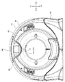
次に、カバー16の詳細について図2及び図3を参照して説明する。図2はX線CT装置の正面図、図3はX線CT装置を斜め後方から見たときの斜視図である。
〔cover〕
The basic configuration of the X-ray CT apparatus has been described above.
Next, details of the
ここで、環状回転体12の前方、後方、両側方、上方、及び下方に配置されている架台11の部位を、前面部、後面部、側面部、天井部及び底部という場合がある。また、左右方向(両側方向)、上下方向(高さ方向)、及び、体軸方向(前後方向)をX軸方向、Y軸方向、及び、Z軸方向という場合がある。なお、架台11の後面部をフレーム13という場合がある。
Here, the parts of the
また、図2及び図3において、環状回転体12の前方及び後方をZ1及びZ2で示し、さらに、環状回転体12の右側方及び左側方をX1及びX2で示し、さらに、環状回転体12の上方及び下方をY1及びY2で示す。 2 and 3, the front and rear of the annular rotator 12 are indicated by Z1 and Z2, and the right and left sides of the annular rotator 12 are indicated by X1 and X2. The upper and lower parts are indicated by Y1 and Y2.
図2及び図3に示すように、カバー16は、架台11の底部を覆う底カバー161と、架台11の前面部を覆う前カバー162と、架台11の後面部を覆う後カバー163と、架台11の天井部を覆う天井カバー164と、架台11の側面部を覆う側面カバー165とを有している。
As shown in FIGS. 2 and 3, the
前カバー162は筒口前部162aを有している。筒口前部162aは、筒状に形成され、開口部15の略前半分をZ軸方向(体軸方向)から覆うように開口部15に前方から嵌め込まれている。
The
後カバー163は筒口後部163aを有している。筒口後部163aは、筒状に形成され、開口部15の略後半分をZ軸方向から覆うように開口部15に後方から嵌め込まれている。筒口前部162a及び筒口後部163aにより筒側部が構成されている。
The
後カバー163の上部には、後述する放熱器26からの熱をカバー16の外部に放出するための排気口163bが設けられている。排気口163bは、図2及び図3に示す12時の位置に設けられている。放熱器26からの熱はカバー16内部で上昇するために、後カバー163の上部に設けられた排気口163bから効率よく熱を放出することが可能となる。排気口163bを通してX線CT装置の正面側に伝わるカバー16内部からの騒音は、前カバー162や底カバー161の前面部に排気口163bが設けられたときに比較して、低減される。
An
放熱器26からの熱を効率よく放出するため、排気口163bは、カバー16の上部にもうけられていればよい。例えば、排気口163bは天井カバー164に設けられてもよい。
In order to efficiently release the heat from the radiator 26, the
後述するダクト50の一部は後カバー163により覆われている。また、後述するファン41及びダクト50の他の部分は、側面カバー165により覆われている。なお、ファン41及びダクト50の他の部分は、他のカバー16、例えば、天井カバー164により覆われてもよい。
A part of the duct 50 described later is covered with a
〔冷却手段、ダクト〕
冷却手段40はファン41を有している。ファン41は、放熱器26の近傍に配置され、放熱器26からの熱をダクト50に送り出すものである。ダクト50は、架台11とカバー16との間に配置され、ファン41からの排気を受けて排気口163bに導くものである。カバー内部からの騒音としては、ファン41が回転しているときの風切り音及びそれを駆動するモータの音が含まれる。
[Cooling means, duct]
The cooling means 40 has a
〔防音構造〕
次に、カバー16内部からの騒音を低減するための防音構造について説明する。
(Soundproof structure)
Next, a soundproof structure for reducing noise from the inside of the
(比較例に係る防音構造)
先ず、比較例に係る防音構造について図4を参照して説明する。図4は、一つの防音部材により構成された防音構造の断面図である。図4では、開口部15を体軸方向(Z軸方向)に沿って切断したときの断面図を示している。
(Soundproof structure according to comparative example)
First, a soundproof structure according to a comparative example will be described with reference to FIG. FIG. 4 is a cross-sectional view of a soundproof structure constituted by one soundproof member. FIG. 4 shows a cross-sectional view when the
図4に示すように、前カバー162の筒口前部162aの後端部162dと後カバー163の筒口後部163aの前端部163dとの間にはX線を通すためのX線透過口S1が形成されている。X線透過口S1の周方向の幅は、ビームX線のファン角に対応した大きさになっている。また、X線透過口S1のZ軸方向の幅は、ビームX線のコーン角に対応した大きさになっている。
As shown in FIG. 4, an X-ray transmission port S1 for passing X-rays is formed between the
図4に示すように、X線透過口S1はシート状の防音部材61により塞がれている。それにより、被検者Pが環状回転体12に触れないように安全性を確保することが可能となる。さらに、血液や造影剤が環状回転体12の内部へ進入するのを防止することが可能となる。さらに、カバー16内部からの騒音が外部に漏れるのを防止することが可能となる。
As shown in FIG. 4, the X-ray transmission opening S <b> 1 is closed by a sheet-like
(防音部材の厚さと音響透過損失値との関係)
ここで、防音部材61の厚さと音響透過損失値との関係について図5を参照して説明する。図5は防音部材の厚さと音響透過損失値との関係を示す図である。ここで、音響透過損失値とは、音響透過率の逆数の対数を10倍した量をいい、デシベル[dB]で表される。また、音響透過率とは、入射音の強さに対する透過音の強さの比をいう。
(Relationship between thickness of soundproof member and sound transmission loss value)
Here, the relationship between the thickness of the
図5では、横軸に防音部材の厚さ[mm]を示し、縦軸にコインシデンス効果が起きる周波数[Hz]及び音響透過損失値を示す。ここで、コインシデンス効果とは、特定周波数で音響透過損失値が低下する現象をいう。 In FIG. 5, the horizontal axis represents the thickness [mm] of the soundproof member, and the vertical axis represents the frequency [Hz] at which the coincidence effect occurs and the sound transmission loss value. Here, the coincidence effect refers to a phenomenon in which the sound transmission loss value decreases at a specific frequency.
さらに、図5では、防音層62を設けないときの防音部材61の厚さTに対するコインシデンス効果が起きる周波数を実線で示し、防音層62を設けたときの防音部材61の厚さTに対するコインシデンス効果が起きる周波数を一点鎖線で示し、防音部材61の厚さTに対する音響透過損失値を破線で示す。
Further, in FIG. 5, the frequency at which the coincidence effect occurs with respect to the thickness T of the
防音部材61の厚さTを増していくと、音響透過損失値が高くなって、遮音性が向上する。また、防音部材61の厚さTを増していくと、コインシデンス効果が起きる周波数が低音側に移動する。厚さTがt1のとき周波数を図5にf1で示す。しかし、騒音の周波数特性によっては、厚さTを増すことが、必ずしも遮音性の向上につながらない。たとえば、騒音に周波数f1が含まれると、コインシデンス効果が起きて、音響透過損失値が低下し、遮音性が低下する。そのため、防音部材61の厚さTを上限値t1より薄くする必要がある(T<t1)。
As the thickness T of the
以上に、一つの防音部材61により構成された防音構造について説明した。そして、一つの防音部材61を用いて遮音性能を向上させるには困難を伴うことがわかった。
The soundproof structure constituted by the single
(防音層を設けた防音構造)
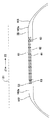
次に、この実施形態に係る防音構造について図6及び図7を参照して説明する。図6は防音層を設けた防音構造の断面図である。図6では開口部15を体軸方向(Z軸方向)に沿って切断したときの断面図を示している。
(Soundproof structure with soundproof layer)
Next, the soundproof structure according to this embodiment will be described with reference to FIGS. FIG. 6 is a cross-sectional view of a soundproof structure provided with a soundproof layer. FIG. 6 shows a cross-sectional view when the
図6に示すように、本実施形態に係る防音構造は二つの防音部材61及び防音層62を有している。それにより、遮音性能を向上させることが可能となる。防音層62は、空気層により構成されている。なお、二つの防音部材61及び防音層62の組み合わせは、二以上設けられてもよい。さらに、防音層62は、吸音部材及び/または音響反射部材により構成されてもよい。
As shown in FIG. 6, the soundproof structure according to the present embodiment includes two
図7は防音部材の部分拡大断面図である。図6及び図7に示すように、防音構造として、防音層62としての空気層を挟むように二つの防音部材61が配置されている。二つの防音部材61は、X線透過口S1に架け渡されるように設けられている。なお、図6及び図7では、二つの防音部材61が並列に配置されたものを示したが、これに限らず、二つの防音部材61が所定の角度を成すように配置されてもよい。
FIG. 7 is a partially enlarged sectional view of the soundproofing member. As shown in FIG.6 and FIG.7, the two
(防音部材)
防音部材61は、音響透過損失の大きな材料であって、X線及びマーキングのためのレーザに対し透過率の良い薄いフィルム状の材料により構成されている。それにより、X線撮影により取得される画像の画質の低下を抑えることが可能となる。
(Soundproof material)
The
防音部材61の種類としては、音のエネルギーの一部が熱のエネルギーに変換され、反射音を小さくする吸音部材と、入射する音を反射、屈折する性質を有する音響反射部材とを含む。
The
吸音部材の例としては、小さな穴がたくさんあいている繊維状のものやスポンジ状のものであって、吸音部材に用いられる材料の代表例として、グラスウールやウレタンなどの多孔質材料が用いられることが好ましい。 Examples of sound absorbing members are fibrous or sponge-like materials with many small holes, and typical examples of materials used for sound absorbing members include porous materials such as glass wool and urethane. Is preferred.
音響反射部材の例としては、ヘリウムなどの空気よりも音速の早い気体を二つの防音部材の間に封入することにより構成されてもよい。 As an example of the acoustic reflecting member, the acoustic reflecting member may be configured by enclosing a gas having a higher speed of sound than air such as helium between two soundproofing members.
この実施形態では、防音部材61として、例えば、ポリエチレンテレフタレート(PET)が用いられている。PETとしてマイラー(登録商標)が用いられことが好ましい。
In this embodiment, as the
防音部材61に用いられる樹脂材料としては、PETに限らず、X線及びレーザ光に対する透過率が高く、耐X線劣化性の高い材料であればよい。
The resin material used for the
防音部材61の厚さは、0.5[mm]〜1.0[mm]であることが好ましい。なお、0.5[mm]の下限を設けた理由は、その厚さの防音部材61に被検者Pが触れても、0.5[mm]以上の厚さがあれば、安全性を担保できることにある。さらに、1.0[mm]の上限を設けた理由は、1.0[mm]以下の厚さであれば、X線及びレーザ光の透過性を確保できることにある。反対に、1.0[mm]を超える厚さになると、X線やレーザ光を吸収し、X線が吸収されたときは、画質の低下の原因となり、レーザ光が吸収されたときは、目印を視認するときの容易さが失われる要因となる。
The thickness of the
次に、上述する材料及び厚さを有する防音部材61の構造について説明する。
Next, the structure of the
防音部材61は、無色透明のフィルムにより構成されてもよい。なお、ここで、「フィルム」には、シート状のものを含む(以下、同様)。
The
これに対し、防音部材61が有色のレーザ光を透過する有色フィルムにより構成されてもよい。防音部材61が有色フィルムにより構成されるとき、フィルムの色は、レーザ光の色に対応する。例えば、赤色レーザのときは、赤色フィルムが用いられ、緑色レーザのときは、緑色フィルムが用いられる。これらの有色フィルムを防音部材61として用いることにより、マーキング用のレーザ光を透過し、他の可視光を透過しないので、防音部材61を通して、装置内部が被検者Pに見えないので、被検者Pに違和感を与えず、外観品質を向上させることができる。
On the other hand, the
防音部材61は、有色フィルムの単体で構成される。これに対して、防音部材61が、有色フィルム及び無色透明フィルムの複合体で構成されてもよい。
The
無色透明フィルムは無色透明の樹脂により成形される。有色フィルムは、無色透明の樹脂を着色することにより成形される。 The colorless and transparent film is formed from a colorless and transparent resin. The colored film is formed by coloring a colorless and transparent resin.
樹脂の着色には顔料や染料などの着色剤が用いられる。顔料には無機顔料、有機顔料が用いられる。染料には、樹脂との相溶性の面から選択されて使用される。染料は、水や溶剤、油などに溶解や分散し、可視光線を吸収することで色相を示す。染料は分子状に分散し、透明樹脂の着色に適する。 Coloring agents such as pigments and dyes are used for coloring the resin. As the pigment, an inorganic pigment or an organic pigment is used. The dye is selected from the aspect of compatibility with the resin. A dye is dissolved or dispersed in water, a solvent, oil or the like, and exhibits a hue by absorbing visible light. The dye is dispersed in a molecular form and is suitable for coloring transparent resins.
樹脂の着色方法には、1)着色剤を樹脂に溶融混練して成形する方法、2)樹脂を成形した後、成型品を着色剤で着色する方法がある。 As a method for coloring the resin, there are 1) a method in which a colorant is melt-kneaded and molded into the resin, and 2) a method in which the molded product is colored with the colorant after the resin is molded.
(空気層)
前述したように、防音層62としての空気層は二つの防音部材61により挟まれている。空気層は、0.5[mm]〜1.0[mm]の厚さを有する両面テープ63により二つの防音部材61を貼り合わせることにより形成されるようにしてもよい。
(Air layer)
As described above, the air layer as the soundproof layer 62 is sandwiched between the two
空気層を設けることで、遮音性を向上させることが可能となる。また、空気層を厚くすることによって、コインシデンス効果が起きる周波数を低下させる。空気層を設けることにより低下した周波数を図5にf2で示す。図5に周波数f2に対する防音部材61の厚さTの上限値をt2で示す。図5に示すように、防音部材61の厚さTの上限値がt2に上がることで、防音部材61の厚さTを増やし(T<t2)、音響透過率損失値を高め、遮音性を向上させることが可能となる。
By providing the air layer, it is possible to improve sound insulation. In addition, by increasing the thickness of the air layer, the frequency at which the coincidence effect occurs is reduced. The frequency lowered by providing the air layer is indicated by f2 in FIG. In FIG. 5, the upper limit value of the thickness T of the
図6及び図7に示すように、筒口前部162aの後端部162dには、段部166が形成されている。また、筒口後部163aの前端部163dには段部166が形成されている。段部166の深さをD、両面テープ63の厚さをtとすると、これらの関係は次の式(2)で表される。
D≧2T+t (2)
As shown in FIG.6 and FIG.7, the
D ≧ 2T + t (2)
また、両面テープ63の長さをW、両方の段部166間の幅をW0、X線透過口S1のZ軸方向の幅をW1とすると、これらの関係は次の式(3)で表される。
W0≧W>W1 (3)
Further, when the length of the double-
W0 ≧ W> W1 (3)
二つの防音部材61が重ねられることにより、遮音効果を上げることが可能となる。また、空気層の厚さの効果で低音域から中音域にかけての遮音性を向上させることが可能となる。
By overlapping the two
両面テープ63が用いられることにより、空気層の密閉性が向上し、それにより、遮音性を向上させることが可能となる。
By using the double-
両面テープ63の板厚を変えることにより、空気層の厚さを変えるようにしてもよい。それにより、コインシデンス効果が起きる所定周波数以下にする。また、二つの防音部材61が所定の角度を成すように配置されてもよい。このとき、両面テープ63の板厚を、筒口前部162aの後端部162d側と筒口後部163aの前端部163d側とで異ならせるようにしてもよい。
The thickness of the air layer may be changed by changing the thickness of the double-
次に、防音部材61によってX線透過口S1を塞ぐ作業手順について説明する。
Next, an operation procedure for closing the X-ray transmission port S1 with the
先ず、段部166に接着剤を塗布する。次に、その接着剤により、1枚の防音部材61を段部166に貼り付ける。
First, an adhesive is applied to the
次に、その1枚の防音部材61に両面テープ63を貼り付ける。次に、その両面テープ63に2枚目の防音部材61を貼り付ける。
Next, the double-
以上の作業により、防音部材61によってX線透過口S1を塞ぐことができる。また、両面テープ63を用いることにより、二枚の防音部材61を簡単に貼り付けることができ、作業性を向上させることが可能となる。
With the above operation, the X-ray transmission port S1 can be blocked by the
なお、両面テープ63により貼り合わせた二枚の防音部材61を、段部166に貼り付けるようにしてもよい。また、段部166に両面テープ63を貼り付け、その両面テープ63に1枚目の防音部材61を貼り付けるようにしてもよい。
In addition, you may make it affix the two
〔他の防音構造〕
次に、弾性部材65について図1、図3及び図8を参照して説明する。図8は、床面とカバー16との間の間隙S2を塞ぐように配置された弾性部材の断面図である。
[Other soundproof structures]
Next, the
図1、図3及び図8に示すように、X線CT装置の設置場所(床面F)と底カバー161の下縁との間には間隙S2が設けられている。間隙S2にはバラツキがある。バラツキは、カバー16の製品精度及び組立精度に起因するため、間隙S2をなくすことは難しい。その間隙S2を通って、カバー16内部からの騒音が外部に漏れる。一方、底カバー161の下縁が床面Fに当たっていると、運転時の振動により異音が発生する。
As shown in FIGS. 1, 3, and 8, a gap S <b> 2 is provided between the installation location (floor surface F) of the X-ray CT apparatus and the lower edge of the
弾性部材65は、弾性を有する材料(例えば、樹脂製ゴム)により帯状に形成されている。弾性部材65の一方の側縁651が底カバー161の下縁に沿って装着されている。弾性部材65の他方の側縁652が床面Fに当たって底カバー161の内側へ撓むことにより、その復元力で床面Fに弾撥的に当接している。それにより、間隙S2を無くすことが可能となる。
The
弾性部材65により間隙S2が塞がれることで、カバー16内部からの騒音を低減することが可能となる。また、弾性部材65の側縁が弾撥的に床面Fに当接しているため、運転時の振動によっても異音が発生することもない。
Since the gap S <b> 2 is closed by the
弾性部材65他方の側縁652は、底カバー161の内側へ撓むように形成されている。弾性部材65の他方の側縁652が底カバー161の内部に隠れるようになるため、外観品質を向上させることが可能となる。
The other side edge 652 of the
また、弾性部材65他方の側縁652は、底カバー161の内側へ撓むように予めその方へ湾曲している。また、撓み易いように、他方の側縁652の板厚は、一方の側縁651を含む他の部分のそれより薄くなっている。
Further, the other side edge 652 of the
なお、この実施形態においては、カバー16の内面に吸音部材が装着されていてもよい。吸音部材の例としては、ロックウールやグラスウールなどの多孔質材料を高密度の板状に形成されたものが用いられる。多孔質材料の一例として、ポリエチレン、ビニルフィルムなどの薄膜が用いられることが好ましい。
In this embodiment, a sound absorbing member may be attached to the inner surface of the
また、実施形態においては、カバー16の内面に入射する音を反射、屈折する性質を有する音響反射部材が装着されていてもよい。
In the embodiment, an acoustic reflection member having a property of reflecting and refracting sound incident on the inner surface of the
本発明のいくつかの実施形態を説明したが、これらの実施形態は、例として提示したものであり、発明の範囲を限定することは意図していない。これら新規な実施形態は、その他の様々な形態で実施されることが可能であり、発明の要旨を逸脱しない範囲で、種々の省略、書き換え、変更を行うことができる。これら実施形態やその変形は、発明の範囲や要旨に含まれるととともに、特許請求の範囲に記載された発明とその均等の範囲に含まれる。 Although several embodiments of the present invention have been described, these embodiments are presented by way of example and are not intended to limit the scope of the invention. These novel embodiments can be implemented in various other forms, and various omissions, rewrites, and changes can be made without departing from the scope of the invention. These embodiments and modifications thereof are included in the scope and gist of the invention, and are included in the invention described in the claims and the equivalents thereof.
P 被検者
S1 X線透過口
S2 間隙
10 X線CT装置
11 架台
111 ファン設置部
112 連通口
12 環状回転体
121 体軸
122 通気口
13 フレーム
14 回転機構
15 開口部
16 カバー
161 底カバー
162 前カバー
162a 筒口前部
163 後カバー
163a 筒口後部
163b 排気口
164 天井カバー
164a 接点
165 側面カバー
166 段部
17 X線管球
18 X線検出器
19 データ収集部(DAS)
20 データ伝送部
21 コンソール
22 スリップリング
23 固定部
24 X線制御部
25 架台制御部
26 放熱器
31 前処理部
32 バスライン
33 システム制御部
34 入力部
35 データ記憶部
36 再構成処理部
37 データ処理部
38 表示部
39 高電圧発生部
40 冷却手段
41 ファン
50 ダクト
61 防音部材
62 防音層
63 両面テープ
65 弾性部材
70 寝台
71 天板
P Subject S1 X-ray transmission port S2 Gap 10
20
Claims (12)
前記X線透過口を塞ぐように配置され、防音層を挟むように設けられたシート状の二つの防音部材と、
薄膜状の基材の両面に接着剤が塗られ、前記二つの防音部材を貼り合わせる両面テープと、
を有する
ことを特徴とするX線CT装置。 Covering the times rotary body which X-ray tube is housed in an inner portion, a cover X-ray transmission port for transmitting X-rays from the X-ray tube is formed,
Two sheet-like soundproof members arranged so as to close the X-ray transmission port and sandwiching a soundproof layer;
Adhesive is applied to both surfaces of the thin-film base material, and a double-sided tape that bonds the two soundproof members;
An X-ray CT apparatus characterized by comprising:
前記X線透過口を塞ぐように配置され、吸音シートにより形成される防音層を挟むように設けられたシート状の二つの防音部材と、
を有することを特徴とするX線CT装置。 Covering the times rotary body which X-ray tube is housed in an inner portion, a cover X-ray transmission port for transmitting X-rays from the X-ray tube is formed,
Two sheet-like soundproof members arranged so as to close the X-ray transmission port and sandwiching a soundproof layer formed by a sound absorbing sheet;
X-ray CT apparatus you, comprising a.
前記X線透過口を塞ぐように配置され、音響反射材により形成される防音層を挟むように設けられたシート状の二つの防音部材と、
を有することを特徴とするX線CT装置。 Covering the times rotary body which X-ray tube is housed in an inner portion, a cover X-ray transmission port for transmitting X-rays from the X-ray tube is formed,
Two sheet-like soundproof members arranged so as to close the X-ray transmission port and sandwiching a soundproof layer formed of an acoustic reflector,
X-ray CT apparatus you, comprising a.
前記防音部材は、有色の前記レーザ光を透過する有色フィルムにより構成されることを特徴とする請求項4に記載のX線CT装置。 By irradiating the body surface of the subject to be inspected with laser light, it is configured to mark the body surface,
The X-ray CT apparatus according to claim 4, wherein the soundproof member is formed of a colored film that transmits the colored laser light.
前記カバーは、筒状に形成され、前記開口部に嵌め込まれることにより、前記開口部の中心側から前記環状回転体を覆う筒側部を有し、前記筒側部に前記X線透過口が形成されたカバーであることを特徴とする請求項1から請求項3のいずれか一項に記載のX線CT装置。 The rotating body is an annular rotating body having an opening at the center,
The cover is formed in a cylindrical shape, and has a cylindrical side portion that covers the annular rotating body from the center side of the opening by being fitted into the opening, and the X-ray transmission port is formed in the cylindrical side. The X-ray CT apparatus according to any one of claims 1 to 3, wherein the X-ray CT apparatus is a formed cover .
Priority Applications (1)
| Application Number | Priority Date | Filing Date | Title |
|---|---|---|---|
| JP2013028922A JP6188347B2 (en) | 2012-02-22 | 2013-02-18 | X-ray CT system |
Applications Claiming Priority (3)
| Application Number | Priority Date | Filing Date | Title |
|---|---|---|---|
| JP2012036172 | 2012-02-22 | ||
| JP2012036172 | 2012-02-22 | ||
| JP2013028922A JP6188347B2 (en) | 2012-02-22 | 2013-02-18 | X-ray CT system |
Publications (3)
| Publication Number | Publication Date |
|---|---|
| JP2013198731A JP2013198731A (en) | 2013-10-03 |
| JP2013198731A5 JP2013198731A5 (en) | 2016-02-25 |
| JP6188347B2 true JP6188347B2 (en) | 2017-08-30 |
Family
ID=49005784
Family Applications (1)
| Application Number | Title | Priority Date | Filing Date |
|---|---|---|---|
| JP2013028922A Active JP6188347B2 (en) | 2012-02-22 | 2013-02-18 | X-ray CT system |
Country Status (4)
| Country | Link |
|---|---|
| US (1) | US9414793B2 (en) |
| JP (1) | JP6188347B2 (en) |
| CN (1) | CN103796591B (en) |
| WO (1) | WO2013125602A1 (en) |
Families Citing this family (3)
| Publication number | Priority date | Publication date | Assignee | Title |
|---|---|---|---|---|
| US10791999B2 (en) * | 2014-02-04 | 2020-10-06 | General Electric Company | Interface for gantry and component |
| CN104775726B (en) * | 2015-03-09 | 2017-03-15 | 江苏建筑职业技术学院 | Shell and tube noise elimination sound proof window |
| US11389126B2 (en) * | 2018-10-31 | 2022-07-19 | General Electric Company | Gantry housing, and medical apparatus |
Family Cites Families (23)
| Publication number | Priority date | Publication date | Assignee | Title |
|---|---|---|---|---|
| US3322233A (en) * | 1964-12-03 | 1967-05-30 | Porter Co H K | Sound control product |
| JPS6338438A (en) | 1986-07-31 | 1988-02-19 | 株式会社東芝 | X-ray ct apparatus |
| US4881251A (en) | 1986-07-31 | 1989-11-14 | Kabushiki Kaisha Toshiba | Computed tomograph apparatus |
| JPH02124139A (en) * | 1988-11-01 | 1990-05-11 | Toshiba Corp | Magnet device for mri and manufacture of the same |
| JP2791150B2 (en) * | 1989-11-22 | 1998-08-27 | 株式会社日立製作所 | Nuclear magnetic resonance equipment |
| JPH05124308A (en) | 1991-11-06 | 1993-05-21 | Brother Ind Ltd | Piezoelectric element driving type printing head |
| JPH08257008A (en) | 1995-03-23 | 1996-10-08 | Hitachi Medical Corp | Magnetic resonance imaging device and its vibration/noise suppressing method |
| JPH1164599A (en) | 1997-08-25 | 1999-03-05 | Shimadzu Corp | X-ray radiating device |
| JP2003026453A (en) * | 2001-07-10 | 2003-01-29 | Naoyoshi Kayama | Pair glass |
| JP2003290211A (en) * | 2002-03-29 | 2003-10-14 | Ge Medical Systems Global Technology Co Llc | X-ray diagnostic system and apparatus |
| CN100457044C (en) * | 2006-04-28 | 2009-02-04 | 上海西门子医疗器械有限公司 | Wind-cooling heat dissipating method of CT device and the apparatus thereof |
| US7465089B2 (en) * | 2007-01-04 | 2008-12-16 | Battle Ronald K | Protective coverings for radiological equipment |
| JP5220374B2 (en) * | 2007-09-27 | 2013-06-26 | ジーイー・メディカル・システムズ・グローバル・テクノロジー・カンパニー・エルエルシー | X-ray CT system |
| US20090141853A1 (en) * | 2007-11-30 | 2009-06-04 | Veronica Crews | Protective shield for ct scanning machine |
| JP5117959B2 (en) * | 2008-08-18 | 2013-01-16 | 三菱樹脂株式会社 | Double glazed windows |
| CN101761732B (en) | 2008-12-24 | 2013-05-08 | 同方威视技术股份有限公司 | Sound insulation system for noise source |
| JP2010227382A (en) * | 2009-03-27 | 2010-10-14 | Toshiba Corp | X-ray ct system |
| JP2010284302A (en) * | 2009-06-11 | 2010-12-24 | Toshiba Corp | X-ray ct apparatus |
| JP2011098070A (en) * | 2009-11-06 | 2011-05-19 | Asahi Keisoku:Kk | Background music device for medical instrument apparatus |
| JP2011254888A (en) * | 2010-06-07 | 2011-12-22 | Toshiba Corp | X-ray ct apparatus |
| GB2483266B (en) * | 2010-09-01 | 2013-03-06 | Echo Barrier Ltd | Sound absorbent barrier |
| US8710842B2 (en) * | 2011-03-07 | 2014-04-29 | General Electric Company | Apparatus and method to reduce noise in magnetic resonance imaging systems |
| US20130129104A1 (en) * | 2011-11-17 | 2013-05-23 | Ashutosh Joshi | System and method for acoustic noise mitigation in a computed tomography scanner |
-
2013
- 2013-02-18 JP JP2013028922A patent/JP6188347B2/en active Active
- 2013-02-20 CN CN201380003062.1A patent/CN103796591B/en active Active
- 2013-02-20 WO PCT/JP2013/054235 patent/WO2013125602A1/en active Application Filing
- 2013-02-20 US US14/235,687 patent/US9414793B2/en active Active
Also Published As
| Publication number | Publication date |
|---|---|
| CN103796591B (en) | 2016-04-20 |
| CN103796591A (en) | 2014-05-14 |
| US20140169532A1 (en) | 2014-06-19 |
| JP2013198731A (en) | 2013-10-03 |
| WO2013125602A1 (en) | 2013-08-29 |
| US9414793B2 (en) | 2016-08-16 |
Similar Documents
| Publication | Publication Date | Title |
|---|---|---|
| JP5159965B1 (en) | X-ray CT system | |
| JP6116930B2 (en) | X-ray CT system | |
| EP2325626A1 (en) | Apparatus for multi-modal imaging | |
| JP6188347B2 (en) | X-ray CT system | |
| US9254108B2 (en) | Gantry with bore safety mechanism | |
| TWI572331B (en) | Rotation type optical fault scanner | |
| US20100177867A1 (en) | Gantry x-ray transmissive element | |
| JP2016530912A (en) | Radiation window for medical imaging system | |
| US20110242092A1 (en) | Image display system | |
| US20130129104A1 (en) | System and method for acoustic noise mitigation in a computed tomography scanner | |
| US20180110494A1 (en) | Portable medical device and method of controlling portable medical device | |
| JP5674299B2 (en) | Apparatus and method for Z-position dependent X-ray beam filtering of an imaging system | |
| US9113784B2 (en) | Apparatus and method for multi-modal imaging | |
| JP5984248B2 (en) | X-ray CT gantry | |
| US11793474B2 (en) | Lighting arrangement for a medical imaging system | |
| JP2013169393A (en) | X-ray ct apparatus | |
| JP2011254888A (en) | X-ray ct apparatus | |
| JP2005087366A5 (en) | ||
| US20180177477A1 (en) | X-ray computed tomography apparatus and gantry apparatus | |
| JP6500016B2 (en) | Method for determining a hazardous area between a test object and an X-ray inspection system | |
| JP2018102925A (en) | X-ray computed tomography apparatus and gantry device | |
| JP6951092B2 (en) | Radiation detector, scintillator array, and scintillator array manufacturing method | |
| JP6800684B2 (en) | Radiation imaging device | |
| JP2000333943A (en) | Ct device and method for forming shield structure of ct device | |
| JP2019122458A (en) | Measuring device |
Legal Events
| Date | Code | Title | Description |
|---|---|---|---|
| A521 | Request for written amendment filed |
Free format text: JAPANESE INTERMEDIATE CODE: A523 Effective date: 20151228 |
|
| A621 | Written request for application examination |
Free format text: JAPANESE INTERMEDIATE CODE: A621 Effective date: 20151228 |
|
| A711 | Notification of change in applicant |
Free format text: JAPANESE INTERMEDIATE CODE: A711 Effective date: 20160527 |
|
| A977 | Report on retrieval |
Free format text: JAPANESE INTERMEDIATE CODE: A971007 Effective date: 20161012 |
|
| A131 | Notification of reasons for refusal |
Free format text: JAPANESE INTERMEDIATE CODE: A131 Effective date: 20161108 |
|
| A521 | Request for written amendment filed |
Free format text: JAPANESE INTERMEDIATE CODE: A523 Effective date: 20170110 |
|
| TRDD | Decision of grant or rejection written | ||
| A01 | Written decision to grant a patent or to grant a registration (utility model) |
Free format text: JAPANESE INTERMEDIATE CODE: A01 Effective date: 20170704 |
|
| A61 | First payment of annual fees (during grant procedure) |
Free format text: JAPANESE INTERMEDIATE CODE: A61 Effective date: 20170801 |
|
| R150 | Certificate of patent or registration of utility model |
Ref document number: 6188347 Country of ref document: JP Free format text: JAPANESE INTERMEDIATE CODE: R150 |
|
| S533 | Written request for registration of change of name |
Free format text: JAPANESE INTERMEDIATE CODE: R313533 |
|
| R350 | Written notification of registration of transfer |
Free format text: JAPANESE INTERMEDIATE CODE: R350 |