JP6185516B2 - Air compressor equipment - Google Patents
Air compressor equipment Download PDFInfo
- Publication number
- JP6185516B2 JP6185516B2 JP2015127154A JP2015127154A JP6185516B2 JP 6185516 B2 JP6185516 B2 JP 6185516B2 JP 2015127154 A JP2015127154 A JP 2015127154A JP 2015127154 A JP2015127154 A JP 2015127154A JP 6185516 B2 JP6185516 B2 JP 6185516B2
- Authority
- JP
- Japan
- Prior art keywords
- plate
- air
- side plate
- cylinder
- hole
- Prior art date
- Legal status (The legal status is an assumption and is not a legal conclusion. Google has not performed a legal analysis and makes no representation as to the accuracy of the status listed.)
- Active
Links
- 238000000926 separation method Methods 0.000 claims description 147
- 239000002184 metal Substances 0.000 claims description 51
- 230000006835 compression Effects 0.000 claims description 28
- 238000007906 compression Methods 0.000 claims description 28
- 238000003032 molecular docking Methods 0.000 claims description 26
- 230000007246 mechanism Effects 0.000 claims description 17
- 230000017525 heat dissipation Effects 0.000 claims description 15
- 239000000463 material Substances 0.000 claims description 14
- 230000004308 accommodation Effects 0.000 claims description 13
- 239000004033 plastic Substances 0.000 claims description 11
- 238000003825 pressing Methods 0.000 claims description 11
- 230000002093 peripheral effect Effects 0.000 claims description 9
- 230000000694 effects Effects 0.000 claims description 4
- 238000002347 injection Methods 0.000 claims description 4
- 239000007924 injection Substances 0.000 claims description 4
- 230000005855 radiation Effects 0.000 claims description 4
- 230000005540 biological transmission Effects 0.000 claims description 3
- 238000001816 cooling Methods 0.000 claims description 2
- 239000007769 metal material Substances 0.000 description 6
- 239000002991 molded plastic Substances 0.000 description 3
- 238000013459 approach Methods 0.000 description 2
- 238000013461 design Methods 0.000 description 2
- 238000012986 modification Methods 0.000 description 2
- 230000004048 modification Effects 0.000 description 2
- 230000000149 penetrating effect Effects 0.000 description 2
- 230000002411 adverse Effects 0.000 description 1
- 238000004891 communication Methods 0.000 description 1
- 230000008878 coupling Effects 0.000 description 1
- 238000010168 coupling process Methods 0.000 description 1
- 238000005859 coupling reaction Methods 0.000 description 1
- 230000002349 favourable effect Effects 0.000 description 1
- 238000002844 melting Methods 0.000 description 1
- 230000008018 melting Effects 0.000 description 1
- 238000000034 method Methods 0.000 description 1
- 230000008569 process Effects 0.000 description 1
- 238000009423 ventilation Methods 0.000 description 1
Images


Classifications
-
- F—MECHANICAL ENGINEERING; LIGHTING; HEATING; WEAPONS; BLASTING
- F04—POSITIVE - DISPLACEMENT MACHINES FOR LIQUIDS; PUMPS FOR LIQUIDS OR ELASTIC FLUIDS
- F04B—POSITIVE-DISPLACEMENT MACHINES FOR LIQUIDS; PUMPS
- F04B53/00—Component parts, details or accessories not provided for in, or of interest apart from, groups F04B1/00 - F04B23/00 or F04B39/00 - F04B47/00
- F04B53/08—Cooling; Heating; Preventing freezing
-
- F—MECHANICAL ENGINEERING; LIGHTING; HEATING; WEAPONS; BLASTING
- F04—POSITIVE - DISPLACEMENT MACHINES FOR LIQUIDS; PUMPS FOR LIQUIDS OR ELASTIC FLUIDS
- F04B—POSITIVE-DISPLACEMENT MACHINES FOR LIQUIDS; PUMPS
- F04B39/00—Component parts, details, or accessories, of pumps or pumping systems specially adapted for elastic fluids, not otherwise provided for in, or of interest apart from, groups F04B25/00 - F04B37/00
- F04B39/06—Cooling; Heating; Prevention of freezing
- F04B39/066—Cooling by ventilation
-
- F—MECHANICAL ENGINEERING; LIGHTING; HEATING; WEAPONS; BLASTING
- F04—POSITIVE - DISPLACEMENT MACHINES FOR LIQUIDS; PUMPS FOR LIQUIDS OR ELASTIC FLUIDS
- F04B—POSITIVE-DISPLACEMENT MACHINES FOR LIQUIDS; PUMPS
- F04B39/00—Component parts, details, or accessories, of pumps or pumping systems specially adapted for elastic fluids, not otherwise provided for in, or of interest apart from, groups F04B25/00 - F04B37/00
- F04B39/12—Casings; Cylinders; Cylinder heads; Fluid connections
-
- F—MECHANICAL ENGINEERING; LIGHTING; HEATING; WEAPONS; BLASTING
- F04—POSITIVE - DISPLACEMENT MACHINES FOR LIQUIDS; PUMPS FOR LIQUIDS OR ELASTIC FLUIDS
- F04B—POSITIVE-DISPLACEMENT MACHINES FOR LIQUIDS; PUMPS
- F04B41/00—Pumping installations or systems specially adapted for elastic fluids
- F04B41/02—Pumping installations or systems specially adapted for elastic fluids having reservoirs
-
- F—MECHANICAL ENGINEERING; LIGHTING; HEATING; WEAPONS; BLASTING
- F04—POSITIVE - DISPLACEMENT MACHINES FOR LIQUIDS; PUMPS FOR LIQUIDS OR ELASTIC FLUIDS
- F04B—POSITIVE-DISPLACEMENT MACHINES FOR LIQUIDS; PUMPS
- F04B53/00—Component parts, details or accessories not provided for in, or of interest apart from, groups F04B1/00 - F04B23/00 or F04B39/00 - F04B47/00
- F04B53/10—Valves; Arrangement of valves
-
- F—MECHANICAL ENGINEERING; LIGHTING; HEATING; WEAPONS; BLASTING
- F04—POSITIVE - DISPLACEMENT MACHINES FOR LIQUIDS; PUMPS FOR LIQUIDS OR ELASTIC FLUIDS
- F04B—POSITIVE-DISPLACEMENT MACHINES FOR LIQUIDS; PUMPS
- F04B53/00—Component parts, details or accessories not provided for in, or of interest apart from, groups F04B1/00 - F04B23/00 or F04B39/00 - F04B47/00
- F04B53/16—Casings; Cylinders; Cylinder liners or heads; Fluid connections
-
- F—MECHANICAL ENGINEERING; LIGHTING; HEATING; WEAPONS; BLASTING
- F04—POSITIVE - DISPLACEMENT MACHINES FOR LIQUIDS; PUMPS FOR LIQUIDS OR ELASTIC FLUIDS
- F04B—POSITIVE-DISPLACEMENT MACHINES FOR LIQUIDS; PUMPS
- F04B35/00—Piston pumps specially adapted for elastic fluids and characterised by the driving means to their working members, or by combination with, or adaptation to, specific driving engines or motors, not otherwise provided for
- F04B35/01—Piston pumps specially adapted for elastic fluids and characterised by the driving means to their working members, or by combination with, or adaptation to, specific driving engines or motors, not otherwise provided for the means being mechanical
-
- F—MECHANICAL ENGINEERING; LIGHTING; HEATING; WEAPONS; BLASTING
- F04—POSITIVE - DISPLACEMENT MACHINES FOR LIQUIDS; PUMPS FOR LIQUIDS OR ELASTIC FLUIDS
- F04B—POSITIVE-DISPLACEMENT MACHINES FOR LIQUIDS; PUMPS
- F04B35/00—Piston pumps specially adapted for elastic fluids and characterised by the driving means to their working members, or by combination with, or adaptation to, specific driving engines or motors, not otherwise provided for
- F04B35/04—Piston pumps specially adapted for elastic fluids and characterised by the driving means to their working members, or by combination with, or adaptation to, specific driving engines or motors, not otherwise provided for the means being electric
-
- F—MECHANICAL ENGINEERING; LIGHTING; HEATING; WEAPONS; BLASTING
- F04—POSITIVE - DISPLACEMENT MACHINES FOR LIQUIDS; PUMPS FOR LIQUIDS OR ELASTIC FLUIDS
- F04B—POSITIVE-DISPLACEMENT MACHINES FOR LIQUIDS; PUMPS
- F04B39/00—Component parts, details, or accessories, of pumps or pumping systems specially adapted for elastic fluids, not otherwise provided for in, or of interest apart from, groups F04B25/00 - F04B37/00
- F04B39/14—Provisions for readily assembling or disassembling
-
- F—MECHANICAL ENGINEERING; LIGHTING; HEATING; WEAPONS; BLASTING
- F05—INDEXING SCHEMES RELATING TO ENGINES OR PUMPS IN VARIOUS SUBCLASSES OF CLASSES F01-F04
- F05C—INDEXING SCHEME RELATING TO MATERIALS, MATERIAL PROPERTIES OR MATERIAL CHARACTERISTICS FOR MACHINES, ENGINES OR PUMPS OTHER THAN NON-POSITIVE-DISPLACEMENT MACHINES OR ENGINES
- F05C2225/00—Synthetic polymers, e.g. plastics; Rubber
Landscapes
- Engineering & Computer Science (AREA)
- Mechanical Engineering (AREA)
- General Engineering & Computer Science (AREA)
- Compressor (AREA)
- Compressors, Vaccum Pumps And Other Relevant Systems (AREA)
- Massaging Devices (AREA)
Description
本発明は、空気圧縮機装置に関し、特に、金属材料により製作されたメタルシートが弁体に密着されて高い気密度を得る上、高温により弁体の接触面が熔融して気密度が低下することを防ぐ空気圧縮機装置に関する。 The present invention relates to an air compressor device, and in particular, a metal sheet made of a metal material is brought into close contact with a valve body to obtain a high air density, and the contact surface of the valve body is melted at a high temperature to lower the air density. The present invention relates to an air compressor device that prevents this.
従来のプラスチック材料からなる空気圧縮機は、空気貯蔵ユニットと、ピストン本体が往復運動するシリンダーと、を含む。シリンダー頂部の排気口には、バルブが設けられる。バルブは、シリンダーと空気貯蔵ユニットとの間に配設され、シリンダーがプラスチック材料からなるため、ピストン本体がシリンダー内で往復運動する際に生じる熱エネルギーによりシリンダーが変形し、シリンダー頂部の排気口の接触部が非平坦、非平滑な接触面となり易く、長期間にわたり開閉動作が行われると気密度が低下し、圧縮機のピストン本体がシリンダー室内で往復運動を行う速度に悪影響を与えてしまうことがあり、空気圧縮機の空気圧縮性能を向上させることができずに、ピストン本体がシリンダー内で往復運動を行う際に発生させる高温の熱エネルギーを筐体から速やかに排出することができずに筐体中に熱が溜まってしまい、空気圧縮機の駆動により発生する熱エネルギーを速やかに低減させることができず、安全性は好ましくなかった。この問題を改善するために、本発明者は空気圧縮機装置を開発した。この空気圧縮機装置は、筐体及び弁体を含む。この筐体の内部には、電源をオンすると空気圧力を発生させる空気圧縮機が設けられている。空気圧縮機は、ピストン本体を往復運動させるシリンダーを有する。シリンダーと、モータを固定するメインハウジングとは、一体成形されたプラスチック材料からなる構造を有する。シリンダー頂部の排気端には、シリンダーの圧縮室と連通する通気孔が形成されている。シリンダー頂部は、一体成形されてメタルシートを覆う。メタルシートの内部には、通気孔と連通する貫通孔が形成される。弁体は、ばねの付勢力により押圧されて貫通孔に密着される。弁体と金属材料からなるメタルシートとが密着されているため、高い気密度を得ることができる上、高温により弁体の接触面が熔融して気密度が低下してしまうことを防ぐこともできる。 A conventional air compressor made of a plastic material includes an air storage unit and a cylinder in which a piston body reciprocates. A valve is provided at the exhaust port at the top of the cylinder. The valve is disposed between the cylinder and the air storage unit. Since the cylinder is made of a plastic material, the cylinder is deformed by the heat energy generated when the piston body reciprocates in the cylinder, and the exhaust at the top of the cylinder is The contact part tends to be a non-flat, non-smooth contact surface, and if the opening / closing operation is performed for a long period of time, the air density is lowered, and the speed at which the piston body of the compressor reciprocates in the cylinder chamber is adversely affected. The air compression performance of the air compressor cannot be improved, and the high-temperature heat energy generated when the piston body reciprocates in the cylinder cannot be quickly discharged from the housing. Heat accumulates in the housing, and the heat energy generated by driving the air compressor cannot be quickly reduced. It is not preferable. In order to remedy this problem, the present inventor has developed an air compressor device. The air compressor device includes a housing and a valve body. An air compressor that generates air pressure when the power is turned on is provided inside the housing. The air compressor has a cylinder that reciprocates the piston body. The cylinder and the main housing for fixing the motor have a structure made of an integrally molded plastic material. A vent hole communicating with the compression chamber of the cylinder is formed at the exhaust end of the top of the cylinder. The cylinder top is integrally formed to cover the metal sheet. A through hole communicating with the vent hole is formed inside the metal sheet. The valve body is pressed by the biasing force of the spring and is brought into close contact with the through hole. Since the valve body and the metal sheet made of a metal material are in close contact with each other, it is possible to obtain a high air density and prevent the contact surface of the valve body from being melted due to a high temperature, thereby reducing the air density. it can.
本発明の第1の目的は、筐体及び弁体を含み、筐体の内部には、電源をオンすると空気圧力を発生させる空気圧縮機が設けられ、空気圧縮機のシリンダーと、モータを固定するメインハウジングとが一体成形されたプラスチック材料からなる構造を有し、シリンダー頂部の排気端には、シリンダーの圧縮室と連通する通気孔が形成され、シリンダー頂部は、一体成形されてメタルシートを覆い、メタルシートの内部には、通気孔と連通する貫通孔が形成され、弁体は、ばねの付勢力により押圧されて貫通孔に密着され、弁体と金属材料とからなるメタルシートとが密着されているため、気密度が高い空気圧縮機装置を提供することにある。
本発明の第2の目的は、シリンダーの頂壁内部に形成された空気孔とメタルシート内部に形成された貫通孔とはサブ圧力貯蔵チャンバとして用いることができる空気圧縮機装置を提供することにある。
本発明の第3の目的は、筐体が上蓋体及び下ベースボディを含み、上蓋体内に設けた90度で折り曲げたL字状分離プレートと、それに対応した下ベースボディの逆L字状分離プレートとが結合され、空気圧縮機の運転により発生した空気流は、順次組み合わせて結合した上蓋体内のL字状分離プレートの短辺、円弧円及び長辺と、下ベースボディの逆L字状分離プレートの短辺、円弧辺及び長辺とを介し、空気流がメインハウジングに結合されたシリンダーへスムーズに案内され、空気流の経路がシリンダーの外周へ案内され、シリンダーは好ましい放熱効果を得ることができ、空気流の経路は、ピストン本体の頂端に形成された吸気孔を介してシリンダー内部へ進入し、シリンダー内部に発生する熱エネルギーを速やかに低減させて気体注入速度を高め、安全性が高い空気圧縮機装置を提供することにある。
A first object of the present invention includes a housing and a valve body, and an air compressor that generates air pressure when the power is turned on is provided inside the housing, and the cylinder of the air compressor and the motor are fixed. The main housing is made of an integrally molded plastic material, and a vent hole communicating with the compression chamber of the cylinder is formed at the exhaust end of the top of the cylinder. The top of the cylinder is integrally molded to form a metal sheet. A through hole communicating with the ventilation hole is formed inside the cover and the metal sheet, the valve body is pressed by the biasing force of the spring and is in close contact with the through hole, and the metal sheet made of the valve body and a metal material is An object of the present invention is to provide an air compressor device having a high air density because of the close contact.
A second object of the present invention is to provide an air compressor apparatus in which an air hole formed in the top wall of a cylinder and a through hole formed in a metal sheet can be used as a sub pressure storage chamber. is there.
The third object of the present invention is to provide an L-shaped separation plate bent at 90 degrees provided in the upper lid body, and a corresponding lower L-shaped separation of the lower base body. The air flow generated by the operation of the air compressor is combined with the plate, and the short side, the circular arc and the long side of the L-shaped separation plate in the upper lid body combined in order and the inverted L-shape of the lower base body The air flow is smoothly guided to the cylinder connected to the main housing through the short side, the arc side and the long side of the separation plate, the air flow path is guided to the outer periphery of the cylinder, and the cylinder has a favorable heat dissipation effect. The air flow path enters the cylinder through an intake hole formed at the top end of the piston body, and the heat energy generated inside the cylinder is quickly reduced to gas. Increasing the input rate is to provide a highly safe air compressor device.
上記課題を解決するために、本発明の第1の形態によれば、筐体を含む空気圧縮機装置であって、前記筐体内には、電源オンにより空気圧力を発生させる空気圧縮機が内蔵され、前記空気圧縮機は、ピストン本体を駆動させるシリンダーと、モータを固定するメインハウジングとを有し、前記メインハウジングには、前記空気圧縮機の動力機構が固定され、前記動力機構は、前記シリンダー内で前記ピストン本体を往復運動させ、前記シリンダー内の圧縮空気が押し出されて前記空気圧縮機の空気貯蔵ユニット内へ進入し、前記空気貯蔵ユニットには、前記空気貯蔵ユニットと連通する複数のマニホールドが設けられ、前記空気圧縮機は、前記ピストン本体を駆動させる前記シリンダーと、前記モータを固定する前記メインハウジングとを一体成形するプラスチック材料からなり、前記シリンダー頂部の排気端には、前記シリンダーの圧縮室と連通する空気孔が形成され、前記シリンダー頂部は、一体成形されてメタルシートを覆い、前記メタルシート内には、空気孔と連通する貫通孔が形成され、弁体がばねの付勢力により押圧されて前記貫通孔に密着され、金属からなる前記メタルシートが前記弁体に密着され、前記空気圧縮機の前記ピストン本体が前記シリンダーの前記圧縮室で往復運動する際に行われる前記弁体の開閉が長期間行われた場合でも、前記弁体と前記貫通孔との気密度が高く維持される上、高温により前記弁体の接触面が熔融して気密度が低下することを防ぐことを特徴とする空気圧縮機装置が提供される。 In order to solve the above-described problem, according to a first aspect of the present invention, an air compressor device including a housing, wherein an air compressor that generates air pressure when the power is turned on is built in the housing. The air compressor has a cylinder for driving the piston body and a main housing for fixing the motor, and a power mechanism of the air compressor is fixed to the main housing, and the power mechanism is The piston body is reciprocated in a cylinder, and compressed air in the cylinder is pushed out and enters the air storage unit of the air compressor. The air storage unit includes a plurality of air communication units that communicate with the air storage unit. A manifold is provided, and the air compressor unites the cylinder for driving the piston body and the main housing for fixing the motor. An air hole communicating with the compression chamber of the cylinder is formed at the exhaust end of the cylinder top, and the cylinder top is integrally molded to cover the metal sheet. A through hole communicating with the air hole is formed, and the valve body is pressed by a biasing force of a spring to be in close contact with the through hole, the metal sheet made of metal is in close contact with the valve body, and the air compressor Even when the valve body is opened and closed for a long time when the piston body reciprocates in the compression chamber of the cylinder, the air density between the valve body and the through hole is maintained high, Thus, an air compressor device is provided that prevents the contact surface of the valve body from melting and the air density from being lowered.
前記筐体は、上蓋体と下ベースボディとの組み合わせにより構成され、前記上蓋体の外観面には、前記空気圧縮機をオン・オフするスイッチと、使用者が圧力計を見るためのウインドウと、複数の吸気孔と、排気用の複数の通気孔と、が設けられ、前記上蓋体内には、複数の分離プレートと、前記分離プレートにより画成された少なくとも1つの収容空間と、が設けられ、前記下ベースボディ内には、複数の分離プレートと、前記分離プレートにより画成された少なくとも1つの収容空間と、が設けられ、前記上蓋体及び前記下ベースボディに設けた前記収容空間は、前記上蓋体と前記下ベースボディとが組立てられて結合されたとき、互いに対応した空間に形成され、前記上蓋体及び前記下ベースボディに設けた前記分離プレートは、左右反対に配置され、前記空気圧縮機と前記圧力計とは、前記上蓋体及び前記下ベースボディ内の前記分離プレート間に安定的に収容されることが好ましい。 The casing is configured by a combination of an upper lid and a lower base body, and an external surface of the upper lid includes a switch for turning on and off the air compressor, and a window for a user to view the pressure gauge. A plurality of air intake holes and a plurality of air exhaust holes are provided, and a plurality of separation plates and at least one accommodation space defined by the separation plates are provided in the upper lid body. In the lower base body, a plurality of separation plates and at least one accommodation space defined by the separation plates are provided, and the accommodation spaces provided in the upper lid body and the lower base body are: When the upper lid body and the lower base body are assembled and joined, the separation plates provided in the upper lid body and the lower base body are formed in spaces corresponding to each other. Are arranged in pairs, the and the air compressor the pressure gauge, the upper lid member and stably accommodated are preferably between the separating plate of the lower base within the body.
前記下ベースボディは、底板を含み、前記底板の周囲には、前側板、後側板、左側板及び右側板を含む複数の側板が設けられ、前記前側板、前記後側板、前記左側板及び前記右側板は、互いに対向する2組の側板であり、互いに隣接した2つの前記側板には、完全に貫通された複数の吸気孔と排気用の通気孔とが間隔をあけて設けられ、前記吸気孔は、前記前側板に形成され、前記通気孔は、前記左側板に形成され、前記後側板には、切欠きが凹設され、前記複数の分離プレートは、長分離プレート、短分離プレート、斜め分離プレート、逆L字状分離プレート及び横分離プレートを含み、前記長分離プレートは、前記前側板から前記後側板へ向かって縦向きに延び、前記短分離プレートは、前記前側板から前記後側板へ向かって縦向きで延びるとともに、前記斜め分離プレートの前端に接続され、前記斜め分離プレートの末端は、前記右側板へ向かって傾き、一直線で延びて末端が前記右側板に近接し、前記逆L字状分離プレートは、長辺及び短辺を有し、前記右側板に対して平行な前記短辺の前端は、前記斜め分離プレートの末端に接続され、前記短辺の末端は、前記前側板に対して平行な前記長辺の一端に接続され、前記短辺と前記長辺との垂直接続箇所には、滑らかな円弧辺が設けられ、前記長辺の他端は、前記左側板へ向かって延び、前記左側板に近接した前記長辺には、完全に貫通された複数の通気孔が間隔をおいて設けられ、前記前側板、前記長分離プレート、前記左側板、前記逆L字状分離プレート、前記斜め分離プレート及び前記短分離プレートにより画成された収容空間には、前記空気圧縮機が収容され、前記前側板及び前記左側板に形成された前記吸気孔及び前記通気孔を介し、外気が前記収容空間と連通し、前記前側板の前記吸気孔前側の前記長分離プレート及び前記短分離プレートとの間には、前記前側板に対して平行な下円弧縁プレートが設けられ、前記下ベースボディの内面には、斜面を有する導流ブロックが設けられ、前記放熱羽根により発生された冷気が前記モータの前記切欠き内へ案内されて前記モータ内を速やかに冷却し、前記モータが連続運転により焼損することを防ぐことが好ましい。 The lower base body includes a bottom plate, and a plurality of side plates including a front side plate, a rear side plate, a left side plate, and a right side plate are provided around the bottom plate, and the front side plate, the rear side plate, the left side plate, and the The right side plates are two sets of side plates facing each other, and the two side plates adjacent to each other are provided with a plurality of completely penetrating intake holes and exhaust vent holes spaced from each other. A hole is formed in the front side plate, the vent hole is formed in the left side plate, a notch is formed in the rear side plate, and the plurality of separation plates include a long separation plate, a short separation plate, Including an oblique separation plate, an inverted L-shaped separation plate and a lateral separation plate, wherein the long separation plate extends vertically from the front side plate to the rear side plate, and the short separation plate extends from the front side plate to the rear side. Extend vertically to the side plate And the end of the oblique separation plate is inclined toward the right side plate, extends in a straight line, the end is close to the right side plate, and the inverted L-shaped separation plate is The front end of the short side having a long side and a short side and parallel to the right side plate is connected to the end of the oblique separation plate, and the end of the short side is parallel to the front side plate. Connected to one end of the long side, a smooth arc side is provided at a vertical connection portion between the short side and the long side, and the other end of the long side extends toward the left side plate, and the left side On the long side close to the plate, a plurality of completely penetrated air holes are provided at intervals, the front side plate, the long separation plate, the left side plate, the inverted L-shaped separation plate, the diagonal Defined by the separation plate and the short separation plate The accommodation space accommodates the air compressor, and outside air communicates with the accommodation space via the intake holes and the vent holes formed in the front side plate and the left side plate, and the intake holes of the front side plate A lower arc edge plate parallel to the front plate is provided between the long separation plate and the short separation plate on the front side, and a flow guide block having a slope is provided on the inner surface of the lower base body. It is preferable that the cool air generated by the heat radiating blades is guided into the notch of the motor to quickly cool the inside of the motor and prevent the motor from burning out by continuous operation.
前記上蓋体は底板を有し、前記底板の周囲には、前側板、後側板、左側板及び右側板を含む複数の側板が設けられ、前記前側板、前記後側板、前記左側板及び前記右側板は、互いに対向する2組の側板であり、互いに隣接した2つの前記側板には、完全に貫通された複数の吸気孔と排気用の通気孔とが間隔をあけて設けられ、前記吸気孔は、前記前側板に形成され、前記通気孔は、前記右側板に形成され、前記後側板には、切欠きが凹設され、前記複数の分離プレートは、長分離プレート、短分離プレート、斜め分離プレート及びL字状分離プレートを含み、前記長分離プレートは、前記前側板から前記後側板へ向かって縦向きに延び、前記短分離プレートは、前記前側板から前記後側板へ向かって縦向きで延びるとともに、前記斜め分離プレートの前端に接続され、前記斜め分離プレートの末端は、前記左側板へ向かって傾き、一直線で延びて末端が前記左側板に近接し、前記L字状分離プレートは、長辺及び短辺を有し、前記左側板に対して平行な前記短辺の前端は、前記斜め分離プレートの末端に接続され、前記短辺の末端は、前記前側板に対して平行な前記長辺の一端に接続され、前記短辺と前記長辺との垂直接続箇所には、滑らかな円弧辺が設けられ、前記長辺の他端は、前記右側板へ向かって延び、前記右側板に近接した前記長辺には、複数の通気孔が完全に貫通されて間隔をおいて設けられ、前記前側板、前記長分離プレート、前記右側板、前記L字状分離プレート、前記斜め分離プレート及び前記短分離プレートにより画成された収容空間には、前記空気圧縮機が収容され、前記前側板及び前記右側板に形成された前記吸気孔及び前記通気孔を介し、外気が前記収容空間と連通し、前記前側板の前記吸気孔前側の前記長分離プレート及び前記短分離プレートとの間には、前記前側板に対して平行な上円弧縁プレートが設けられ、前記上蓋体の内面には、斜面を有する導流ブロックが設置され、前記放熱羽根により発生された冷気が前記モータの前記切欠き内へ案内され、前記モータ内を速やかに冷却することにより、前記モータが連続運転により焼損することを防ぐことが好ましい。 The upper lid has a bottom plate, and a plurality of side plates including a front side plate, a rear side plate, a left side plate and a right side plate are provided around the bottom plate, and the front side plate, the rear side plate, the left side plate and the right side plate are provided. The plates are two sets of side plates facing each other, and the two side plates adjacent to each other are provided with a plurality of completely penetrating intake holes and exhaust vent holes at intervals, and the intake holes Is formed in the front side plate, the vent hole is formed in the right side plate, the rear side plate is notched, and the plurality of separation plates are a long separation plate, a short separation plate, an oblique Including a separation plate and an L-shaped separation plate, wherein the long separation plate extends vertically from the front plate toward the rear plate, and the short separation plate extends vertically from the front plate toward the rear plate And the diagonal separation block Connected to the front end of the cable, the end of the oblique separation plate is inclined toward the left side plate, extends in a straight line, the end is close to the left side plate, and the L-shaped separation plate has a long side and a short side. The front end of the short side parallel to the left side plate is connected to the end of the oblique separation plate, and the end of the short side is connected to one end of the long side parallel to the front side plate. A smooth circular arc side is provided at a vertical connection portion between the short side and the long side, and the other end of the long side extends toward the right side plate and is close to the right side plate. In the side, a plurality of vent holes are completely penetrated and spaced apart, and the front plate, the long separation plate, the right plate, the L-shaped separation plate, the oblique separation plate, and the short separation plate In the housing space defined by The outside air communicates with the housing space through the intake holes and the vent holes formed in the front side plate and the right side plate, and the long separation plate and the short separation in front of the intake hole of the front side plate An upper arc edge plate parallel to the front side plate is provided between the plates, and a flow guide block having a slope is installed on the inner surface of the upper lid, and the cold air generated by the heat radiating blades is It is preferable to prevent the motor from burning out by continuous operation by being guided into the notch of the motor and quickly cooling the inside of the motor.
前記動力機構は、モータと、伝動用の小歯車と、小歯車と噛合される大歯車と、クランクピンを有する重量回転盤と、放熱用の放熱羽根とを含み、前記メインハウジングは、互いに離間した2つの軸孔を有し、そのうちの1つの前記軸孔を介し、前記小歯車を前端に有する前記モータが固定され、前記モータの後端には、前記放熱用の放熱羽根が設けられ、前記モータの外周縁には、切欠きが凹設され、前記大歯車には、前記重量回転盤が結合され、前記重量回転盤には、軸杆及びクランクピンが設けられ、前記軸杆の一端は、前記大歯車に挿通され、他方の前記軸孔に設けた軸受の孔に枢着され、前記クランクピンの一端は、前記ピストン本体の末端に枢着され、前記ピストン本体の頂端に設けられたピストンヘッドは、吸気口を有し、前記小歯車が前記大歯車と噛合され、前記メインハウジングが有する前記2つの軸孔の左右両側には、導流孔がそれぞれ形成され、前記導流孔を介して軸方向で前記放熱羽根により発生される空気流を導入し、かつ、前記メインハウジングの両側縁部及び下縁には、円形状の集風フードが設けられ、前記集風フードと、前記軸受が設置された前記軸孔との間に放射線状に配置された複数の斜め羽根により、螺旋状の気流を導入して前記軸受の放熱を行うことが好ましい。 The power mechanism includes a motor, a transmission small gear, a large gear meshed with the small gear, a heavy turntable having a crankpin, and a heat dissipation blade for heat dissipation, and the main housings are separated from each other. The motor having the small gear at its front end is fixed through one of the shaft holes, and at the rear end of the motor, the heat dissipation blade for heat dissipation is provided, A notch is recessed in an outer peripheral edge of the motor, the heavy wheel is coupled to the large gear, a shaft rod and a crank pin are provided on the heavy wheel, and one end of the shaft rod is provided. Is inserted through the large gear and is pivotally attached to a bearing hole provided in the other shaft hole, and one end of the crank pin is pivotally attached to the end of the piston body and provided at the top end of the piston body. The piston head has an inlet and a front A small gear is engaged with the large gear, and flow guide holes are respectively formed on the left and right sides of the two shaft holes of the main housing, and are generated by the heat radiating blades in the axial direction through the flow guide holes. And a circular air collecting hood is provided on both side edges and the lower edge of the main housing, between the air collecting hood and the shaft hole in which the bearing is installed. Preferably, the bearings are radiated by introducing a spiral air flow with a plurality of diagonally arranged blades.
前記放熱羽根は、前記筐体の前記前側板に形成された前記吸気孔を介して外気が導入され、組み合わせて結合した下円弧縁プレート及び上円弧縁プレートにより画成された導風開口を介し、前記収容空間中に外気をスムーズに導入して乱流の発生を防ぎ、前記下ベースボディ及び前記上蓋体の内面に設けた前記導流ブロックが前記モータの前記切欠きの外表面に当接され、前記導流ブロックの斜面により前記モータの前記切欠きに空気流が直接吸引され、前記切欠きを介して前記モータ内の高温気流が排出されて前記モータが放熱されるため、溜まった熱により前記モータが損壊することを防いで前記モータの使用寿命を延ばすことができる上、空気流が前記筐体の前記短分離プレート及び前記斜め分離プレートにより前記メインハウジングの前記集風フードに至るまで案内され、放射状に配列された前記斜め羽根に進入して螺旋状の気流が導入され、前記軸受及び前記動力機構により放熱を行い、前記メインハウジングの前記導流孔により軸向きで空気流が導入され、互いに組み合わされた前記下ベースボディの前記逆L字状分離プレートの前記短辺、前記円弧辺、前記長辺と、前記上蓋体内の前記L字状分離プレートの前記短辺、前記円弧辺及び前記長辺とを空気流が順次通り、前記メインハウジングに結合された前記シリンダーへスムーズに案内され、前記空気流は、一方の経路により前記シリンダーの外周へ案内されて、前記シリンダーの放熱効果を高めることができる上、他方の経路により前記ピストン本体の頂端に形成された前記吸気口を介して前記シリンダー内へ進入し、前記シリンダー内に発生した熱エネルギーを速やかに低減させ、気体の注入速度を高めることが好ましい。 The heat radiating blade is introduced through the air intake hole formed in the front side plate of the housing, and through an air guide opening defined by a lower arc edge plate and an upper arc edge plate joined in combination. The outside air is smoothly introduced into the housing space to prevent the occurrence of turbulent flow, and the flow guide block provided on the inner surfaces of the lower base body and the upper lid body is in contact with the outer surface of the notch of the motor. Since the air flow is directly sucked into the notch of the motor by the inclined surface of the flow guide block, the high-temperature air flow in the motor is discharged through the notch and the motor is dissipated, so that the accumulated heat The motor can be prevented from being damaged by this, and the service life of the motor can be extended. In addition, the main housing can be operated by the short separation plate and the oblique separation plate of the housing. Guided to the air collecting hood, entering the oblique blades arranged radially, a spiral air flow is introduced, heat is radiated by the bearing and the power mechanism, and by the flow guide holes of the main housing The short side, the arc side, and the long side of the inverted L-shaped separation plate of the lower base body combined with each other, in which an air flow is introduced in an axial direction, and the L-shaped separation plate of the upper lid body The air flow sequentially passes through the short side, the arc side, and the long side, and is smoothly guided to the cylinder coupled to the main housing, and the air flow is guided to the outer periphery of the cylinder through one path. In addition, the heat dissipation effect of the cylinder can be enhanced and the other path can be advanced into the cylinder through the intake port formed at the top end of the piston body. And rapidly reduces the heat energy generated in the cylinder, it is preferable to increase the injection velocity of the gas.
前記シリンダーの前記圧縮室頂部の排気端には、頂壁が形成され、前記頂壁は、前記シリンダー上の前記空気貯蔵ユニットに連通する空気孔を有し、前記シリンダーの頂壁は、一体成形されて前記メタルシートを覆い、その上端には当接部が設けられ、前記メタルシートの外周縁には、外環状ショルダが突設され、前記シリンダーの前記頂壁に採用されたプラスチック材料により完全に覆われて一体成形されているため、緩んだり外れたりすることがなく、前記メタルシート内には、前記空気孔と連通した前記貫通孔が形成され、前記貫通孔及び前記空気孔により、前記シリンダーの前記圧縮室と前記空気貯蔵ユニットの内空部とが連通し、前記弁体は、前記メタルシート上の前記当接部の前記貫通孔上端に設置され、前記弁体上には頂面が形成されることが好ましい。 A top wall is formed at an exhaust end of the top of the compression chamber of the cylinder, the top wall has an air hole communicating with the air storage unit on the cylinder, and the top wall of the cylinder is integrally formed. The metal sheet is covered and a contact portion is provided at an upper end thereof, and an outer annular shoulder projects from the outer peripheral edge of the metal sheet, and is completely made of a plastic material employed for the top wall of the cylinder. In the metal sheet, the through-hole communicating with the air hole is formed, and the through-hole and the air hole are used to form the through-hole and the air hole. The compression chamber of the cylinder communicates with the inner space of the air storage unit, and the valve body is installed at the upper end of the through hole of the contact portion on the metal sheet, and the top surface is on the valve body But It made it is preferable.
前記頂壁の前記空気孔及び前記メタルシート内に形成された前記貫通孔の縦向き深さは、前記弁体の縦向き厚さより大きく、サブ圧力貯蔵チャンバとして用い、前記サブ圧力貯蔵チャンバの存在により、前記サブ圧力貯蔵チャンバの容積に等しい圧縮空気が前記シリンダーの前記圧縮室内に存在することが好ましい。 The vertical depth of the air hole in the top wall and the through hole formed in the metal sheet is larger than the vertical thickness of the valve body, and is used as a sub pressure storage chamber, and the presence of the sub pressure storage chamber Therefore, it is preferable that compressed air equal to the volume of the sub pressure storage chamber exists in the compression chamber of the cylinder.
矩形状を呈するトップカバーは、上端につまみを有し、前記トップカバーの中心部には、下方へ延びた円筒柱が延設され、前記円筒柱には、外方へ延びた複数の環状ショルダが間隔をおいて形成され、前記トップカバーと前記環状ショルダとの間には、凹状環状溝が複数形成され、前記円筒柱は、底端縁を有し、前記底端縁には、前記円筒柱の内部中心へ向かう凸状押圧部が形成され、前記押圧部は頂面を有し、前記円筒柱上の前記環状溝には、複数のシールリングが嵌合され、前記トップカバーは、前記空気貯蔵ユニット上に対応して結合され、前記つまみを回転させると前記トップカバーが前記空気貯蔵ユニット上に強固に係合されて緩むことを防ぎ、前記ばねは、一端が前記弁体上に設置され、他端が前記トップカバーの前記円筒柱上の前記環状ショルダに当接されることが好ましい。 The top cover having a rectangular shape has a knob at the upper end, and a cylindrical column extending downward is extended at the center of the top cover. The cylindrical column has a plurality of annular shoulders extending outward. Are formed at intervals, and a plurality of concave annular grooves are formed between the top cover and the annular shoulder, the cylindrical column has a bottom edge, and the cylinder is formed on the bottom edge. A convex pressing portion toward the inner center of the column is formed, the pressing portion has a top surface, a plurality of seal rings are fitted into the annular groove on the cylindrical column, and the top cover is Correspondingly coupled on the air storage unit, rotating the knob prevents the top cover from being firmly engaged on the air storage unit and loosening, and the spring has one end installed on the valve body And the other end is on the cylindrical column of the top cover It is preferably abuts against the annular shoulder.
前記シリンダー頂部の排気端は、頂壁を有し、前記頂壁は、外方へ水平に延びた前部フランジを有し、前記前部フランジ上には、互いに対応した2つのドッキングプレートが設けられ、その末端には、互いに対応して逆に反り返った2つの嵌合クランプが設けられ、前記嵌合クランプの内側面と前記ドッキングプレートとの間には収容槽が形成され、前記シリンダーの頂壁には、上方へ延びた円柱状接続部が延設され、その外周側部には、前記シールリングが嵌合される環溝が形成され、前記接続部内には、前記頂壁及び前記圧縮室と連通する空気孔が形成され、前記接続部上のテーブル面は、一体成形されて前記メタルシートを覆い、それは上方へ延びたフランジを有し、前記フランジの上端には当接部が形成され、前記メタルシートの外周縁には、外環状ショルダが突設され、それは前記シリンダーの頂壁に採用されたプラスチック材料により完全に覆われて一体成形されるため、緩んだり外れたりしてしまう虞がなく、前記メタルシート内には、前記空気孔と連通する貫通孔が形成され、前記貫通孔及び前記空気孔を介して前記シリンダーの前記圧縮室と前記空気貯蔵ユニットの前記内空部とが連通し、前記シリンダーにより圧縮された圧縮空気が排出されて前記空気貯蔵ユニットの前記内空部へ直接進入し、前記筒柱状空気貯蔵ユニットは、開口及び内空部を一端に有し、前記空気貯蔵ユニットの開口には、周囲に拡大した拡張フランジが設けられ、前記拡張フランジには、互いに対応した2つのドッキングプレートが設けられ、前記ドッキングプレートには、垂直に延びた側当て板が延設され、前記側当て板の末端には、反対方向へ垂直に延びた短翼板が延設され、前記短翼板、前記側当て板、前記ドッキングプレートにより収納槽が画成され、前記空気貯蔵ユニットの内側面の中心部には、下方へ延びた円筒柱が延設され、前記円筒柱の外周には環状ショルダが設けられ、前記環状ショルダと前記円筒柱との間には、凹状環溝が形成され、前記環溝には、前記ばねが収納され、前記ばねの他端には、前記円筒柱が嵌入されて前記環溝内に着座し、前記空気貯蔵ユニットを回転させて前記空気貯蔵ユニットの前記拡張フランジの前記ドッキングプレートを、前記シリンダーの前記前部フランジ上に設けた前記嵌合クランプ中に速やかに進入させて結合させ、前記ドッキングプレートが前記収容槽中に収容され、前記ドッキングプレートが前記収納槽中に収容されて前記側当て板により阻まれて回転前進することを防ぎ、前記シリンダーに前記空気貯蔵ユニットが強固に結合され、前記シリンダーと前記空気貯蔵ユニットとが着脱自在に結合されることが好ましい。 The exhaust end of the top of the cylinder has a top wall, the top wall has a front flange extending horizontally outward, and two docking plates corresponding to each other are provided on the front flange. At the end, two fitting clamps that warp in opposite directions are provided, and a receiving tank is formed between the inner surface of the fitting clamp and the docking plate, and the top of the cylinder is formed. The wall is provided with a cylindrical connecting portion extending upward, and an annular groove is formed in the outer peripheral side portion of the wall, and the top wall and the compression are formed in the connecting portion. An air hole communicating with the chamber is formed, and the table surface on the connecting portion is integrally formed to cover the metal sheet, and has a flange extending upward, and a contact portion is formed at the upper end of the flange. Outside the metal sheet At the edge, an outer annular shoulder is projected, which is completely covered with the plastic material adopted for the top wall of the cylinder and integrally molded, so there is no risk of loosening or coming off, and the metal sheet A through hole communicating with the air hole is formed therein, and the compression chamber of the cylinder communicates with the inner space of the air storage unit via the through hole and the air hole. Compressed compressed air is discharged and directly enters the inner space of the air storage unit. The cylindrical columnar air storage unit has an opening and an inner space at one end, and the opening of the air storage unit An extended flange is provided around the periphery, and the extension flange is provided with two docking plates corresponding to each other, and the docking plate extends vertically. A side abutting plate is extended, and a short wing plate extending perpendicularly in the opposite direction is extended at the end of the side abutting plate, and a storage tank is defined by the short wing plate, the side abutting plate, and the docking plate. A cylindrical column extending downward is provided at the center of the inner side surface of the air storage unit, and an annular shoulder is provided on the outer periphery of the cylindrical column, between the annular shoulder and the cylindrical column. Is formed with a concave annular groove, the spring is accommodated in the annular groove, and the cylindrical pillar is fitted into the other end of the spring and is seated in the annular groove, and the air storage unit is The docking plate of the expansion flange of the air storage unit is rotated to quickly enter the coupling clamp provided on the front flange of the cylinder to be coupled, and the docking plate is in the storage tank. Housed in front The docking plate is accommodated in the storage tank and is prevented from rotating forward by being blocked by the side pad, the air storage unit is firmly coupled to the cylinder, and the cylinder and the air storage unit are attached and detached. It is preferable that they are freely combined.
以下、本発明の実施形態について図に基づいて説明する。なお、これによって本発明が限定されるものではない。 Hereinafter, embodiments of the present invention will be described with reference to the drawings. Note that the present invention is not limited thereby.
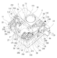
図1及び図2を参照する。図1及び図2に示すように、本発明の一実施形態に係る空気圧縮機装置は、筐体を含む。筐体内には、空気圧縮機が内蔵される(図3を参照する)。空気圧縮機は、ピストン本体38を駆動させるシリンダー4と、モータ34を固定するメインハウジング3とを有する。メインハウジング3には、空気圧縮機の動力機構が固定される。動力機構は、モータ34と、伝動用の小歯車35と、小歯車35と噛合される大歯車36と、クランクピン372を有する重量回転盤37と、放熱用の放熱羽根39とを含む。モータ34により空気圧縮機の動力機構が駆動されると、シリンダー4の内円周壁40内でピストン本体38のピストンヘッド381が往復式圧縮動作を行い、空気孔42を介して圧縮された空気で弁体51を押動するとばね52が圧縮され、圧縮された空気が空気貯蔵ユニット6内に進入する。空気貯蔵ユニット6には、それぞれ異なる性質、機能を有するオブジェクトと接続されたマニホールド62,63,64,65が空気貯蔵ユニット6と連通するように複数設けられている。例えば、マニホールド62にはホース(図示せず)が接続され、マニホールド63には圧力計91が接続され、マニホールド64には安全弁92が取り付けられている。本発明の構造の主な特徴は、シリンダー4と、モータ34が固定されるメインハウジング3とが一体成形されたプラスチック材料からなる点にある。シリンダー4頂部の排気端には、シリンダー4の圧縮室43と連通する空気孔42が形成され、シリンダー4頂部が一体成形されてメタルシート44を覆う。メタルシート44内には、空気孔42と連通する貫通孔440が形成される。弁体51は、ばね52の付勢力により押圧され、貫通孔440に弁体51が密着され、金属材料により製作されたメタルシート44が弁体51に密着され、高い気密度を得ることができる。
Please refer to FIG. 1 and FIG. As shown in FIG.1 and FIG.2, the air compressor apparatus which concerns on one Embodiment of this invention contains a housing | casing. An air compressor is built in the housing (see FIG. 3). The air compressor has a
図2を参照する。図2に示すように、本実施形態の筐体は、上蓋体1と下ベースボディ2とが組み合わされて構成される。上蓋体1の外観面には、空気圧縮機をオン・オフするスイッチ102と、使用者が圧力計91を見るためのウインドウ101と、複数の吸気孔110と、排気用の複数の通気孔140と、が設けられている。上蓋体1内には、複数の分離プレートと、分離プレートにより画成された少なくとも1つの収容空間と、が設けられる。下ベースボディ2内には、複数の分離プレートと、分離プレートにより画成された少なくとも1つの収容空間と、が設けられる。上蓋体1及び下ベースボディ2に設けた収容空間は、上蓋体1と下ベースボディ2とが組立てられて結合されたとき、互いに対応した空間に形成される。上蓋体1及び下ベースボディ2に設けた複数の分離プレートは、左右反対に配置される。空気圧縮機と圧力計91とは、上蓋体1及び下ベースボディ2内の分離プレート間に安定的に収容される。
Please refer to FIG. As shown in FIG. 2, the housing of the present embodiment is configured by combining an upper lid body 1 and a
本実施形態の下ベースボディ2は、底板を含む。底板の周囲には、前側板21、後側板22、左側板23及び右側板24を含む複数の側板が設けられている。前側板21、後側板22、左側板23及び右側板24は、互いに対向する2組の側板である。互いに隣接した2つの側板には、完全に貫通された複数の吸気孔210と排気用の通気孔230とが間隔をあけて設けられている。本実施形態において、吸気孔210は、前側板21に形成され、通気孔230は、左側板23に形成され、後側板22には、切欠き221が凹設される。前述した複数の分離プレートは、長分離プレート25、短分離プレート26、斜め分離プレート27、逆L字状分離プレート28及び横分離プレートを含む。長分離プレート25は、前側板21から後側板22へ向かって縦向きに延びる。短分離プレート26は、前側板21から後側板22へ向かって縦向きで延びるとともに、斜め分離プレート27の前端に接続される。斜め分離プレート27の末端は、右側板24へ向かって傾き、一直線で延びて末端が右側板24に近接する。逆L字状分離プレート28は、長辺281及び短辺282を有する。右側板24に対して平行な短辺282の前端は、斜め分離プレート27の末端に接続される。短辺282の末端は、前側板21に対して平行な長辺281の一端に接続される。短辺282と長辺281との垂直接続箇所には、滑らかな円弧辺283が設けられる。長辺281の他端は、左側板23へ向かって延び、左側板23に近接した長辺281には、完全に貫通された複数の通気孔280が間隔をおいて設けられている。前述した前側板21、長分離プレート25、左側板23、逆L字状分離プレート28、斜め分離プレート27及び短分離プレート26により画成された収容空間には、空気圧縮機が収容される。前述した前側板21及び左側板23に形成された吸気孔210及び通気孔230を介し、外気が収容空間と連通し、前側板21の吸気孔210前側の長分離プレート25及び短分離プレート26との間には、前側板21に対して平行な下円弧縁プレート293が設けられる。下ベースボディ2の内面には、斜面292を有する導流ブロック291が設けられる。
The
上蓋体1は底板を有する。底板の周囲には、前側板11、後側板12、左側板13及び右側板14を含む複数の側板が設けられる。前側板11、後側板12、左側板13及び右側板14は、互いに対向する2組の側板である。互いに隣接した2つの側板には、完全に貫通された複数の吸気孔110と排気用の通気孔140とが間隔をあけて設けられる。本実施形態において、吸気孔110は、前側板11に形成され、通気孔140は、右側板14に形成され、後側板12には、切欠き121が凹設される。前述した複数の分離プレートは、長分離プレート15、短分離プレート16、斜め分離プレート17及びL字状分離プレート18を含む。長分離プレート15は、前側板11から後側板12へ向かって縦向きに延びる。短分離プレート16は、前側板11から後側板12へ向かって縦向きで延びるとともに、斜め分離プレート17の前端に接続される。斜め分離プレート17の末端は、左側板13へ向かって傾き、一直線で延びて末端が左側板13に近接する。L字状分離プレート18は、長辺181及び短辺182を有する。左側板13に対して平行な短辺182の前端は、斜め分離プレート17の末端に接続される。短辺182の末端は、前側板11に対して平行な長辺181の一端に接続される。短辺182と長辺181との垂直接続箇所には、滑らかな円弧辺183が設けられる。長辺181の他端は、右側板14へ向かって延び、右側板14に近接した長辺181には、複数の通気孔280が完全に貫通されて間隔をおいて設けられている。前述した前側板11、長分離プレート15、右側板14、L字状分離プレート18、斜め分離プレート17及び短分離プレート16により画成された収容空間には、空気圧縮機が収容される。前述した前側板11及び右側板14に形成された吸気孔110及び通気孔140を介し、外気が収容空間と連通し、前側板11の吸気孔110前側の長分離プレート15及び短分離プレート16との間には、前側板11に対して平行な上円弧縁プレート193が設けられる。上蓋体1の内面には、斜面192を有する導流ブロック191が設置される。斜面192は、前述した導流ブロック291の斜面292と同じ機能を有する。
The upper lid 1 has a bottom plate. Around the bottom plate, a plurality of side plates including a
図3を参照する。図3に示すように、前述の空気圧縮機に設けたメインハウジング3は、互いに離間した2つの軸孔を有し、そのうち1つの軸孔を介し、小歯車35を前端に有するモータ34が固定される。モータ34の後端には、放熱用の放熱羽根39が設けられる。モータ34の外周縁には、対応した切欠き340が凹設され、前述の大歯車36には、重量回転盤37が結合される。重量回転盤37には、軸杆371及びクランクピン372が設けられる。軸杆371の一端は、大歯車36に挿通され、他方の軸孔30に設けた軸受301の孔に枢着される。クランクピン372の一端は、ピストン本体38の末端に枢着される。ピストン本体38の頂端に設けられたピストンヘッド381は、吸気口380を有する(図7を併せて参照する)。このとき小歯車35は、大歯車36と噛合される。メインハウジング3が有する2つの軸孔30の左右両側には導流孔31が形成され、導流孔31を介して軸方向で放熱羽根39が発生させた空気流を導入し、かつ、メインハウジング3の両側縁部及び下縁には、円形状の集風フード32が設けられる。集風フード32と、軸受301が設置された軸孔30との間に放射線状に配置された複数の斜め羽根33は、螺旋状の気流を導入して軸受301の放熱を行う。モータ34が運転されると、小歯車35により大歯車36が駆動され、シリンダー4内でピストン本体38が往復式の圧縮動作を行い、発生した圧縮空気が空気貯蔵ユニット6内に進入する。
Please refer to FIG. As shown in FIG. 3, the
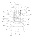
図3〜図5に示すように、本実施形態のシリンダー4は、一体化されるか接続されてメインハウジング3と結合され、一体成形されたプラスチック材料からなる構造を構成する。シリンダー4の圧縮室43頂部の排気端には頂壁41が形成される。頂壁41は、シリンダー4上の空気貯蔵ユニット6と連通する空気孔42を有する。シリンダー4の頂壁41は、一体成形されてメタルシート44を覆い、その上端には当接部442が設けられる。メタルシート44の外周縁には、外環状ショルダ441が突設され、シリンダー4の頂壁41に採用されたプラスチック材料により完全に覆われて一体成形されているため、緩んだり外れたりする欠点がない。メタルシート44内には、空気孔42と連通した貫通孔440が形成されている。貫通孔440及び空気孔42は、シリンダー4の圧縮室43と空気貯蔵ユニット6の内空部61とを連通させる。弁体51は、前述したメタルシート44上の当接部442の貫通孔440上端に設置され、弁体51上には頂面511が形成されている(図5を参照する)。前述した頂壁41の空気孔42及びメタルシート44内に形成された貫通孔440の縦向き深さは、前述した弁体51の縦向き厚さより大きく、サブ圧力貯蔵チャンバとして用いる。矩形状を呈するトップカバー7(図3及び図5を参照する)は、上端につまみ71を有し、トップカバー7の中心部には下方へ延びた円筒柱72が延設される。円筒柱72には、外方へ延びた複数の環状ショルダ721が間隔をおいて形成される。トップカバー7と環状ショルダ721との間には、凹状環状溝722が複数形成されている。円筒柱72は、底端縁73を有する。底端縁73には、円筒柱72の内部中心へ向かう凸状押圧部74が形成されている。押圧部74は頂面741を有する。複数のシールリング75は、前述した円筒柱72上の環状溝722に嵌合される。前述したトップカバー7は、前述した空気貯蔵ユニット6上に対応して結合され、図4に示すように、つまみ71を回転させてトップカバー7を空気貯蔵ユニット6上に強固に係合させるため、緩む虞がない。また、前述した押圧部74の頂面741から弁体51の頂面511までの距離D(図5を参照する)を調整することにより、圧縮空気の吐出風量と、騒音の大きさを制御することができる。例えば、距離Dが大きくなると、圧縮空気の吐出風量が大きくなるとともに、発生する騒音が大きくなる。反対に、距離Dが小さくなると、圧縮空気の吐出風量が小さくなるとともに、発生する騒音が小さくなる。このように、必要に応じて設計を変えることができる。押圧部74の頂面741から弁体51の頂面511までの距離Dは、円筒柱72の底端縁73から頂面741までの距離に応じて決めることができる。距離Dが大きめであるとき、押圧部74は短くなり、吐出風量が大きくなる。距離Dが小さめであるとき、押圧部74の長さは大きくなり、吐出風量及び騒音が小さくなる。ばね52は、一端が弁体51上に設置され、他端がトップカバー7の円筒柱72上の環状ショルダ721に当接される。
As shown in FIGS. 3 to 5, the
貫通孔440に設置した弁体51により空気の出入りを制御し、依然として空気圧縮機による空気供給が行われていないとき、弁体51がばね52の付勢力により押圧され、貫通孔440に弁体51が密着される(図5を参照する)。金属材料からなるメタルシート44に弁体が密着されている上、メタルシート44の当接部442が非常に滑らかな頂面を有するため、高い気密度を得ることができる。
When the air flow is controlled by the
本発明のシリンダー4の頂壁41内の空気孔42とメタルシート44の貫通孔440とをサブ圧力貯蔵チャンバとして用いることができるため、ピストン本体38が上動行程の上死点に達すると、ピストンヘッド381の頂端面がシリンダー4の圧縮室43頂部の頂壁41に当接されるが(図7を参照する)、サブ圧力貯蔵チャンバの存在により、サブ圧力貯蔵チャンバの容積に等しい圧縮空気がシリンダー4の圧縮室43内に存在する。このような設計により、ピストン本体38の抵抗力が下がって動作がスムーズとなる上、気体注入過程で気体被注入物の圧力値が安全な範囲内に維持されるため、安全性を確保することができる。
Since the
図2を参照する。図2は、本発明の一実施形態に係る空気圧縮機装置の空気圧縮機、圧力計91が筐体に内蔵された状態を示すとともに、放熱導流を表す部分断面斜視図である。図2に示すように、空気圧縮機のモータ34後端に設けられた放熱羽根39が円周に沿って回転する際、放熱羽根39は、筐体の前側板21,11に形成された吸気孔210,110を介して外気が導入され、組み合わせて結合した下円弧縁プレート293及び上円弧縁プレート193により画成された導風開口294,194を介し、収容空間中に外気がスムーズに導入されるため、乱流の発生を防ぎ、下ベースボディ2及び上蓋体1の内面に設けた導流ブロック291,191がモータ34の切欠き340(図3を併せて参照する)の外表面に当接され、導流ブロック291,191の斜面292,192によりモータ34の切欠き340に空気流が直接吸引され、切欠き340を介してモータ34内の高温気流が排出されてモータ34の放熱を行うため、溜まった熱により損壊することを防ぎ、モータ34の使用寿命を延ばすことができる上、空気流は、筐体の短分離プレート26,16及び斜め分離プレート27,17をメインハウジング3の集風フード32に至るまで案内し、放射状に配列された斜め羽根33に進入し、螺旋状の気流が導入され、軸受301及び動力機構により放熱を行うとともに、メインハウジング3の導流孔31を介して軸向きで空気流が導入される。空気流は、互いに組み合わされた下ベースボディ2の逆L字状分離プレート28の短辺282、円弧辺283、長辺281と、上蓋体1内のL字状分離プレート18の短辺182、円弧辺183及び長辺181とを順次通り、メインハウジング3に結合されたシリンダー4へ空気流がスムーズに案内される。空気流は、一方の経路によりシリンダー4の外周へ案内されるため、シリンダー4の放熱効果を高めることができる上、他方の経路によりピストン本体38の頂端に形成された吸気口380を介してシリンダー4内へ進入し、シリンダー4内に発生した熱エネルギーを速やかに低減させ、最終的に、導入された空気流は、下ベースボディ2の左側板23と、逆L字状分離プレート28の長辺281と、下ベースボディ2とが組み合わされて結合された上蓋体1の右側板14、L字状分離プレート18の長辺181に形成された通気孔230,280,140,180から排出される。
Please refer to FIG. FIG. 2 is a partial cross-sectional perspective view showing a state in which an air compressor and a
図6〜図8を参照する。図6〜図8に示すように、本発明の他の実施形態に係る空気圧縮機のシリンダー4頂部の排気端は頂壁41を有する。頂壁41は、外方へ水平に延びた前部フランジ45を有する。前部フランジ45上には、互いに対応した2つのドッキングプレート450が設けられ、その末端には、互いに対応して逆に反り返った2つの嵌合クランプ451が設けられている。嵌合クランプ451の内側面とドッキングプレート450との間には収容槽452が形成され、シリンダー4の頂壁41には、上方へ延びた円柱状接続部46が延設され、その外周側部には、シールリング47が嵌合される環溝461が形成され、接続部46内には、頂壁41及び圧縮室43と連通する空気孔42が形成され、接続部46上側のテーブル面460は、一体成形されてメタルシート48を覆い、それは上方へ延びたフランジ482を有する。フランジ482の上端には当接部483が形成され、メタルシート48の外周縁には、外環状ショルダ481が突設され、それはシリンダー4の頂壁41に採用されたプラスチック材料により完全に覆われて一体成形されるため、緩んだり外れたりしてしまう虞がない。メタルシート48内には、空気孔42と連通する貫通孔480が形成されている。貫通孔480及び空気孔42を介し、シリンダー4の圧縮室43と空気貯蔵ユニット8の内空部82とが連通し、シリンダー4により圧縮された圧縮空気が排出されて空気貯蔵ユニット8の内空部82へ直接進入する。弁体51は、前述したメタルシート48上の当接部483の貫通孔480上端に配設される。また、前述した頂壁41の空気孔42と、メタルシート48内に形成した貫通孔480と、空気孔42及び貫通孔480とは、縦向き深さを弁体51の縦向き厚さより大きくし、サブ圧力貯蔵チャンバとして用いる。
Reference is made to FIGS. As shown in FIGS. 6 to 8, the exhaust end of the top of the
筒柱状空気貯蔵ユニット8は、開口81及び内空部82を一端に有する。空気貯蔵ユニット8の開口81には、周囲に拡大した拡張フランジ85が設けられている。拡張フランジ85には、互いに対応した2つのドッキングプレート851が設けられ、ドッキングプレート851には、垂直に延びた側当て板852が延設されている。側当て板852の末端には、反対方向へ垂直に延びた短翼板853が延設され、短翼板853、側当て板852、ドッキングプレート851により収納槽850が画成され、空気貯蔵ユニット8の内側面の中心部には、下方へ延びた円筒柱86が延設され、円筒柱86の外周には環状ショルダ87が設けられ、環状ショルダ87と円筒柱86との間には、凹状環溝80が形成されている。環溝80には、前述したばね52が収納される。例えば、図7のばね52の他端には、前述した円筒柱86が嵌入されて環溝80内に着座する。空気貯蔵ユニット8には、空気貯蔵ユニット8と連通する複数のマニホールド83,84が設けられている。例えば、マニホールド83,84には、異なる性質、機能を有するオブジェクトが接続される。マニホールド83には、ホース(図示せず)が連結され、マニホールド84には安全弁92が取り付けられる(図6を参照する)。
The cylindrical columnar
図6及び図7を参照する。図6及び図7に示すように、空気貯蔵ユニット8を回転させて空気貯蔵ユニット8の拡張フランジ85のドッキングプレート851を、前述したシリンダー4の前部フランジ45上に設けた嵌合クランプ451中に速やかに進入させて結合させ、ドッキングプレート851が収容槽452中に収容されるとともに、ドッキングプレート450も収納槽850中に収容され、側当て板852により阻まれるため、回転前進することを防ぎ、シリンダー4に空気貯蔵ユニット8が強固に結合される。このシリンダー4と空気貯蔵ユニット8とは着脱自在に結合される。
Please refer to FIG. 6 and FIG. As shown in FIGS. 6 and 7, the
上述したことから分かるように、本発明の空気圧縮機装置は、筐体を含む。筐体内には、電源をオンして空気圧力を発生させる空気圧縮機が内蔵される。空気圧縮機は、ピストン本体38を往復運動させるシリンダー4を含む。シリンダー4は、モータ34を固定するメインハウジング3と一体成形されるプラスチック材料からなる。シリンダー4頂部の排気端には、シリンダー4の圧縮室43と連通する空気孔42が形成され、シリンダー4の頂部は、一体成形されてメタルシート44を覆う。メタルシート44内には、空気孔42と連通する貫通孔440が形成されている。弁体51は、ばね52の付勢力により押圧され、貫通孔440に弁体51が密着され、金属材料に製作されたメタルシート44が弁体51に密着されて高い気密度を得る上、高温により弁体51の接触面が熔融して気密度が低下することを防ぐことができる。
As can be seen from the above, the air compressor device of the present invention includes a housing. An air compressor that turns on the power to generate air pressure is built in the housing. The air compressor includes a
当該分野の技術を熟知するものが理解できるように、本発明の好適な実施形態を前述の通り開示したが、これらは決して本発明を限定するものではない。本発明の主旨と領域を逸脱しない範囲内で各種の変更や修正を加えることができる。従って、本発明の特許請求の範囲は、このような変更や修正を含めて広く解釈されるべきである。 While the preferred embodiments of the present invention have been disclosed above, as may be appreciated by those skilled in the art, they are not intended to limit the invention in any way. Various changes and modifications can be made without departing from the spirit and scope of the present invention. Accordingly, the scope of the claims of the present invention should be construed broadly including such changes and modifications.
1 上蓋体
2 下ベースボディ
3 メインハウジング
4 シリンダー
6 空気貯蔵ユニット
7 トップカバー
8 空気貯蔵ユニット
11 前側板
12 後側板
13 左側板
14 右側板
15 長分離プレート
16 短分離プレート
17 斜め分離プレート
18 L字状分離プレート
21 前側板
22 後側板
23 左側板
24 右側板
25 長分離プレート
26 短分離プレート
27 斜め分離プレート
28 逆L字状分離プレート
30 軸孔
31 導流孔
32 集風フード
33 斜め羽根
34 モータ
35 小歯車
36 大歯車
37 重量回転盤
38 ピストン本体
39 放熱羽根
40 内円周壁
41 頂壁
42 空気孔
43 圧縮室
44 メタルシート
45 前部フランジ
46 接続部
47 シールリング
48 メタルシート
51 弁体
52 ばね
61 内空部
62 マニホールド
63 マニホールド
64 マニホールド
65 マニホールド
71 つまみ
72 円筒柱
73 底端縁
74 押圧部
75 シールリング
80 環溝
81 開口
82 内空部
83 マニホールド
84 マニホールド
85 拡張フランジ
86 円筒柱
87 環状ショルダ
91 圧力計
92 安全弁
101 ウインドウ
102 スイッチ
110 吸気孔
121 切欠き
140 通気孔
180 通気孔
181 長辺
182 短辺
183 円弧辺
191 導流ブロック
192 斜面
193 上円弧縁プレート
194 導風開口
210 吸気孔
221 切欠き
230 通気孔
280 通気孔
281 長辺
282 短辺
283 円弧辺
291 導流ブロック
292 斜面
293 下円弧縁プレート
294 導風開口
301 軸受
340 切欠き
371 軸杆
372 クランクピン
380 吸気口
381 ピストンヘッド
440 貫通孔
441 外環状ショルダ
442 当接部
450 ドッキングプレート
451 嵌合クランプ
452 収容槽
460 テーブル面
461 環溝
480 貫通孔
481 外環状ショルダ
482 フランジ
483 当接部
511 頂面
721 環状ショルダ
722 環状溝
741 頂面
850 収納槽
851 ドッキングプレート
852 側当て板
853 短翼板
DESCRIPTION OF SYMBOLS 1
193 Upper
Claims (9)
前記筐体内には、電源オンにより空気圧力を発生させる空気圧縮機が内蔵され、
前記空気圧縮機は、ピストン本体が往復運動するシリンダーと、メインハウジングとを有し、
前記メインハウジングには、前記空気圧縮機の動力機構が固定され、
前記動力機構は、前記シリンダー内で前記ピストン本体を往復運動させ、前記シリンダー内の圧縮空気が押し出されて前記空気圧縮機の空気貯蔵ユニット内へ進入し、
前記空気貯蔵ユニットには、前記空気貯蔵ユニットと連通する複数のマニホールドが設けられ、
前記空気圧縮機は、前記ピストン本体が往復運動する前記シリンダーと、前記動力機構を固定する前記メインハウジングとを一体成形するプラスチック材料からなり、
前記シリンダーの頂部の排気端には、前記シリンダーの圧縮室と連通する空気孔が形成され、
前記シリンダーの頂部は、一体成形されてメタルシートを覆い、
前記メタルシート内には、空気孔と連通する貫通孔が形成され、
前記筐体は、上蓋体と下ベースボディとの組み合わせにより構成され、
前記上蓋体内には、複数の分離プレートと、前記分離プレートにより画成された少なくとも1つの収容空間と、が設けられ、
前記下ベースボディ内には、複数の分離プレートと、前記分離プレートにより画成された少なくとも1つの収容空間と、が設けられ、
前記複数の分離プレートは、長分離プレート、短分離プレート、斜め分離プレート、逆L字状分離プレート及び横分離プレートを含み、
前記下ベースボディは、底板を含み、
前記底板の周囲には、前側板、後側板、左側板及び右側板を含む複数の側板が設けられ、
前記前側板、前記後側板、前記左側板及び前記右側板は、互いに対向する2組の側板であり、互いに隣接した2つの前記側板には、完全に貫通された複数の吸気孔と排気用の通気孔とが間隔をあけて設けられ、
前記吸気孔は、前記前側板に形成され、
前記通気孔は、前記左側板に形成され、
前記後側板には、切欠きが凹設され、
前記長分離プレートは、前記前側板から前記後側板へ向かって縦向きに延び、
前記短分離プレートは、前記前側板から前記後側板へ向かって縦向きで延びるとともに、前記斜め分離プレートの前端に接続され、
前記斜め分離プレートの末端は、前記右側板へ向かって傾き、一直線で延びて末端が前記右側板に近接し、
前記逆L字状分離プレートは、長辺及び短辺を有し、
前記右側板に対して平行な前記短辺の前端は、前記斜め分離プレートの末端に接続され、前記短辺の末端は、前記前側板に対して平行な前記長辺の一端に接続され、
前記短辺と前記長辺との垂直接続箇所には、滑らかな円弧辺が設けられ、
前記長辺の他端は、前記左側板へ向かって延び、前記左側板に近接した前記長辺には、完全に貫通された複数の通気孔が間隔をおいて設けられ、
前記前側板、前記長分離プレート、前記左側板、前記逆L字状分離プレート、前記斜め分離プレート及び前記短分離プレートにより画成された収容空間には、前記空気圧縮機が収容され、
前記前側板及び前記左側板に形成された前記吸気孔及び前記通気孔を介し、外気が前記収容空間と連通し、前記前側板の前記吸気孔の前側の前記長分離プレート及び前記短分離プレートとの間には、前記前側板に対して平行な下円弧縁プレートが設けられ、前記下ベースボディの内面には、斜面を有する導流ブロックが設けられ、放熱羽根により発生された冷気が前記切欠き内へ案内されて前記動力機構を速やかに冷却し、前記動力機構が連続運転により焼損することを防ぎ、
弁体がばねの付勢力により押圧されて前記貫通孔に密着され、金属からなる前記メタルシートが前記弁体に密着され、前記空気圧縮機の前記ピストン本体が前記シリンダーの前記圧縮室で往復運動する際に行われる前記弁体の開閉が長期間行われた場合でも、前記弁体と前記貫通孔との気密度が高く維持される上、高温により前記弁体の接触面が熔融して気密度が低下することを防ぐことを特徴とする空気圧縮機装置。 An air compressor device including a housing,
An air compressor that generates air pressure when the power is turned on is built in the housing,
The air compressor has a cylinder piston body reciprocates, a main housing,
A power mechanism of the air compressor is fixed to the main housing,
The power mechanism reciprocates the piston body in the cylinder, the compressed air in the cylinder is pushed out and enters the air storage unit of the air compressor,
The air storage unit is provided with a plurality of manifolds communicating with the air storage unit,
The air compressor is made of a plastic material that integrally molds the cylinder in which the piston body reciprocates and the main housing that fixes the power mechanism ,
An air hole communicating with the compression chamber of the cylinder is formed at the exhaust end of the top of the cylinder,
The top of the cylinder is integrally molded to cover the metal sheet,
A through hole communicating with the air hole is formed in the metal sheet,
The housing is configured by a combination of an upper lid and a lower base body,
The upper lid body is provided with a plurality of separation plates and at least one storage space defined by the separation plates,
In the lower base body, a plurality of separation plates and at least one storage space defined by the separation plates are provided,
The plurality of separation plates include a long separation plate, a short separation plate, an oblique separation plate, an inverted L-shaped separation plate, and a lateral separation plate,
The lower base body includes a bottom plate,
Around the bottom plate, a plurality of side plates including a front side plate, a rear side plate, a left side plate and a right side plate are provided,
The front side plate, the rear side plate, the left side plate, and the right side plate are two sets of side plates facing each other, and the two side plates adjacent to each other have a plurality of intake holes that are completely penetrated and exhaust air holes. Vents are provided at intervals,
The air intake hole is formed in the front side plate,
The vent is formed in the left side plate,
The rear side plate has a notch recessed,
The long separation plate extends vertically from the front plate toward the rear plate,
The short separation plate extends in a vertical direction from the front side plate toward the rear side plate, and is connected to a front end of the oblique separation plate,
The end of the oblique separation plate is inclined toward the right side plate, extends in a straight line, and the end is close to the right side plate,
The inverted L-shaped separation plate has a long side and a short side,
The front end of the short side parallel to the right side plate is connected to the end of the oblique separation plate, and the end of the short side is connected to one end of the long side parallel to the front side plate,
A smooth arc side is provided at a vertical connection portion between the short side and the long side,
The other end of the long side extends toward the left side plate, and the long side close to the left side plate is provided with a plurality of completely through holes at intervals.
The air compressor is housed in a housing space defined by the front side plate, the long separation plate, the left side plate, the inverted L-shaped separation plate, the oblique separation plate and the short separation plate,
Outside air communicates with the housing space through the intake holes and the vent holes formed in the front plate and the left plate, and the long separation plate and the short separation plate on the front side of the intake hole of the front plate, In between, a lower arc edge plate parallel to the front plate is provided, and a flow guide block having an inclined surface is provided on the inner surface of the lower base body, and the cold air generated by the heat radiating blades is cut off. The power mechanism is quickly cooled by being guided into the notch, preventing the power mechanism from being burned out by continuous operation,
The valve body is pressed by a biasing force of a spring and is brought into close contact with the through hole, the metal sheet made of metal is brought into close contact with the valve body, and the piston body of the air compressor is reciprocated in the compression chamber of the cylinder. Even when the valve body is opened and closed for a long time, the air density between the valve body and the through hole is maintained high, and the contact surface of the valve body is melted due to high temperature. An air compressor apparatus characterized by preventing a decrease in density.
前記上蓋体及び前記下ベースボディに設けた前記収容空間は、前記上蓋体と前記下ベースボディとが組立てられて結合されたとき、互いに対応した空間に形成され、前記上蓋体及び前記下ベースボディに設けた前記分離プレートは、左右反対に配置され、前記空気圧縮機と前記圧力計とは、前記上蓋体及び前記下ベースボディ内の前記分離プレートの間に安定的に収容されることを特徴とする請求項1に記載の空気圧縮機装置。 A switch for turning on and off the air compressor, a window for a user to view the pressure gauge, a plurality of intake holes, and a plurality of vent holes for exhaust are provided on the outer surface of the upper lid. And
The accommodating space provided in the upper lid and the lower base body is formed in a space corresponding to each other when the upper lid and the lower base body are assembled and coupled, and the upper lid and the lower base body The separation plates provided on the left and right sides are arranged opposite to each other, and the air compressor and the pressure gauge are stably accommodated between the separation plates in the upper lid body and the lower base body. The air compressor device according to claim 1.
前記底板の周囲には、前側板、後側板、左側板及び右側板を含む複数の側板が設けられ、
前記前側板、前記後側板、前記左側板及び前記右側板は、互いに対向する2組の側板であり、互いに隣接した2つの前記側板には、完全に貫通された複数の吸気孔と排気用の通気孔とが間隔をあけて設けられ、前記吸気孔は、前記前側板に形成され、前記通気孔は、前記右側板に形成され、前記後側板には、切欠きが凹設され、
前記複数の分離プレートは、長分離プレート、短分離プレート、斜め分離プレート及びL字状分離プレートを含み、
前記長分離プレートは、前記前側板から前記後側板へ向かって縦向きに延び、
前記短分離プレートは、前記前側板から前記後側板へ向かって縦向きで延びるとともに、前記斜め分離プレートの前端に接続され、
前記斜め分離プレートの末端は、前記左側板へ向かって傾き、一直線で延びて末端が前記左側板に近接し、
前記L字状分離プレートは、長辺及び短辺を有し、
前記左側板に対して平行な前記短辺の前端は、前記斜め分離プレートの末端に接続され、前記短辺の末端は、前記前側板に対して平行な前記長辺の一端に接続され、
前記短辺と前記長辺との垂直接続箇所には、滑らかな円弧辺が設けられ、前記長辺の他端は、前記右側板へ向かって延び、前記右側板に近接した前記長辺には、複数の通気孔が完全に貫通されて間隔をおいて設けられ、
前記前側板、前記長分離プレート、前記右側板、前記L字状分離プレート、前記斜め分離プレート及び前記短分離プレートにより画成された収容空間には、前記空気圧縮機が収容され、前記前側板及び前記右側板に形成された前記吸気孔及び前記通気孔を介し、外気が前記収容空間と連通し、前記前側板の前記吸気孔の前側の前記長分離プレート及び前記短分離プレートとの間には、前記前側板に対して平行な上円弧縁プレートが設けられ、
前記上蓋体の内面には、斜面を有する導流ブロックが設置され、前記放熱羽根により発生された冷気が前記切欠き内へ案内され、前記動力機構を速やかに冷却することにより、前記動力機構が連続運転により焼損することを防ぐことを特徴とする請求項2に記載の空気圧縮機装置。 The upper lid has a bottom plate;
Around the bottom plate, a plurality of side plates including a front side plate, a rear side plate, a left side plate and a right side plate are provided,
The front side plate, the rear side plate, the left side plate, and the right side plate are two sets of side plates facing each other, and the two side plates adjacent to each other have a plurality of intake holes that are completely penetrated and exhaust air holes. A vent hole is provided at an interval, the intake hole is formed in the front side plate, the vent hole is formed in the right side plate, and a notch is provided in the rear side plate,
The plurality of separation plates include a long separation plate, a short separation plate, an oblique separation plate, and an L-shaped separation plate,
The long separation plate extends vertically from the front plate toward the rear plate,
The short separation plate extends in a vertical direction from the front side plate toward the rear side plate, and is connected to a front end of the oblique separation plate,
The end of the oblique separation plate is inclined toward the left side plate, extends in a straight line, and the end is close to the left side plate,
The L-shaped separation plate has a long side and a short side,
The front end of the short side parallel to the left side plate is connected to the end of the oblique separation plate, and the end of the short side is connected to one end of the long side parallel to the front side plate,
A smooth arc side is provided at a vertical connection portion between the short side and the long side, the other end of the long side extends toward the right side plate, and the long side close to the right side plate has A plurality of vents are completely penetrated and spaced apart;
The air compressor is accommodated in an accommodation space defined by the front side plate, the long separation plate, the right side plate, the L-shaped separation plate, the oblique separation plate and the short separation plate, and the front side plate And the outside air communicates with the housing space through the intake hole and the vent hole formed in the right side plate, and is located between the long separation plate and the short separation plate on the front side of the intake hole of the front side plate. Is provided with an upper arc edge plate parallel to the front side plate,
The inner surface of the upper lid body is disposed diversion block having an inclined surface is, the guided cool air generated by the heat radiation vane Previous Symbol notches can, by rapidly cooling the power mechanism, said power mechanism 3. The air compressor device according to claim 2 , wherein the air compressor is prevented from being burned out by continuous operation.
前記メインハウジングは、互いに離間した2つの軸孔を有し、そのうちの1つの前記軸孔を介し、前記小歯車を前端に有する前記モータが固定され、
前記モータの後端には、前記放熱用の放熱羽根が設けられ、
前記モータの外周縁には、切欠きが凹設され、
前記大歯車には、前記重量回転盤が結合され、
前記重量回転盤には、軸杆及びクランクピンが設けられ、
前記軸杆の一端は、前記大歯車に挿通され、他方の前記軸孔に設けた軸受の孔に枢着され、
前記クランクピンの一端は、前記ピストン本体の末端に枢着され、
前記ピストン本体の頂端に設けられたピストンヘッドは、吸気口を有し、前記小歯車が前記大歯車と噛合され、
前記メインハウジングが有する前記2つの軸孔の左右両側には、導流孔がそれぞれ形成され、前記導流孔を介して軸方向で前記放熱羽根により発生される空気流を導入し、かつ、前記メインハウジングの両側縁部及び下縁には、円形状の集風フードが設けられ、
前記集風フードと、前記軸受が設置された前記軸孔との間に放射線状に配置された複数の斜め羽根により、螺旋状の気流を導入して前記軸受の放熱を行うことを特徴とする請求項3に記載の空気圧縮機装置。 The power mechanism includes a motor, a transmission small gear, a large gear meshed with the small gear, a weight rotating disk having a crankpin, and a heat dissipation blade for heat dissipation,
The main housing has two shaft holes spaced apart from each other, and the motor having the small gear at the front end is fixed through one of the shaft holes,
The rear end of the motor is provided with a heat dissipation blade for heat dissipation,
A notch is recessed in the outer peripheral edge of the motor,
The large gear is coupled to the heavy turntable,
The weight turntable is provided with a shaft rod and a crankpin,
One end of the shaft rod is inserted into the large gear and pivotally attached to a bearing hole provided in the other shaft hole,
One end of the crankpin is pivotally attached to the end of the piston body,
The piston head provided at the top end of the piston body has an intake port, and the small gear meshes with the large gear,
On both the left and right sides of the two shaft holes of the main housing, flow guide holes are respectively formed, through which air flow generated by the heat dissipation blades is introduced in the axial direction, and A circular wind collecting hood is provided on both side edges and the lower edge of the main housing,
The bearing radiates heat by introducing a spiral airflow with a plurality of oblique blades arranged radially between the air collecting hood and the shaft hole in which the bearing is installed. The air compressor device according to claim 3 .
前記空気流は、一方の経路により前記シリンダーの外周へ案内されて、前記シリンダーの放熱効果を高めることができる上、他方の経路により前記ピストン本体の頂端に形成された前記吸気口を介して前記シリンダー内へ進入し、前記シリンダー内に発生した熱エネルギーを速やかに低減させ、気体の注入速度を高めることを特徴とする請求項4に記載の空気圧縮機装置。 The heat radiating blade is introduced through the air intake hole formed in the front side plate of the housing, and through an air guide opening defined by a lower arc edge plate and an upper arc edge plate joined in combination. The outside air is smoothly introduced into the housing space to prevent the occurrence of turbulent flow, and the flow guide block provided on the inner surfaces of the lower base body and the upper lid body is in contact with the outer surface of the notch of the motor. Since the air flow is directly sucked into the notch of the motor by the inclined surface of the flow guide block, the high-temperature air flow in the motor is discharged through the notch and the motor is dissipated, so that the accumulated heat The motor can be prevented from being damaged by this, and the service life of the motor can be extended. In addition, the main housing can be operated by the short separation plate and the oblique separation plate of the housing. Guided to the air collecting hood, entering the oblique blades arranged radially, a spiral air flow is introduced, heat is radiated by the bearing and the power mechanism, and by the flow guide holes of the main housing The short side, the arc side, and the long side of the inverted L-shaped separation plate of the lower base body combined with each other, in which an air flow is introduced in an axial direction, and the L-shaped separation plate of the upper lid body An air flow sequentially passes through the short side, the arc side, and the long side, and is smoothly guided to the cylinder coupled to the main housing,
The air flow is guided to the outer periphery of the cylinder by one path, so that the heat dissipation effect of the cylinder can be enhanced, and the air path is formed through the intake port formed at the top end of the piston body by the other path. The air compressor apparatus according to claim 4 , wherein the air compressor apparatus enters the cylinder, rapidly reduces the heat energy generated in the cylinder, and increases a gas injection speed.
前記頂壁は、前記空気貯蔵ユニットに連通する空気孔を有し、
前記シリンダーの頂壁は、一体成形されて前記メタルシートを覆い、その上端には当接部が設けられ、
前記メタルシートの外周縁には、外環状ショルダが突設され、
前記シリンダーの前記頂壁に採用されたプラスチック材料により完全に覆われて一体成形されているため、緩んだり外れたりすることがなく、
前記メタルシートには、前記空気孔と連通した前記貫通孔が形成され、前記貫通孔及び前記空気孔により、前記シリンダーの前記圧縮室と前記空気貯蔵ユニットの内空部とが連通し、
前記弁体は、前記メタルシート上の前記当接部の前記貫通孔の上端に設置され、前記弁体上には頂面が形成されることを特徴とする請求項5に記載の空気圧縮機装置。 A top wall is formed at the exhaust end of the top of the compression chamber of the cylinder,
The top wall has an air hole communicating with the prior SL air storage unit,
The top wall of the cylinder is integrally molded to cover the metal sheet, and an upper end thereof is provided with a contact portion.
An outer annular shoulder projects from the outer peripheral edge of the metal sheet,
Because it is completely covered and integrally molded by the plastic material adopted for the top wall of the cylinder, it does not loosen or come off,
The Metarushi The bets, the is the through hole through air hole and communicating are formed by the through hole and the air hole, through the communicating and the inner hollow portion of the compression chamber and the air storage unit of the cylinder,
The air compressor according to claim 5 , wherein the valve body is installed at an upper end of the through hole of the contact portion on the metal sheet, and a top surface is formed on the valve body. apparatus.
前記サブ圧力貯蔵チャンバの存在により、前記サブ圧力貯蔵チャンバの容積に等しい圧縮空気が前記シリンダーの前記圧縮室内に存在することを特徴とする請求項6に記載の空気圧縮機装置。 The vertical depth of the through hole formed in the air hole of the top wall and the metal sheet is larger than the vertical thickness of the valve body, and is used as a sub pressure storage chamber.
7. The air compressor apparatus according to claim 6 , wherein the presence of the sub pressure storage chamber causes compressed air equal to the volume of the sub pressure storage chamber to exist in the compression chamber of the cylinder.
前記トップカバーの中心部には、下方へ延びた円筒柱が延設され、
前記円筒柱には、外方へ延びた複数の環状ショルダが間隔をおいて形成され、
前記トップカバーと前記環状ショルダとの間には、凹状の環状溝が複数形成され、
前記円筒柱は、底端縁を有し、
前記底端縁には、前記円筒柱の内部中心へ向かう凸状の押圧部が形成され、
前記押圧部は頂面を有し、
前記円筒柱上の前記環状溝には、複数のシールリングが嵌合され、
前記トップカバーは、前記空気貯蔵ユニットの上に対応して結合され、前記つまみを回転させると前記トップカバーが前記空気貯蔵ユニット上に強固に係合されて緩むことを防ぎ、
前記ばねは、一端が前記弁体上に設置され、他端が前記トップカバーの前記円筒柱上の前記環状ショルダに当接されることを特徴とする請求項7に記載の空気圧縮機装置。 The top cover that has a rectangular shape has a knob at the upper end,
At the center of the top cover, a cylindrical pillar extending downward is extended,
In the cylindrical column, a plurality of annular shoulders extending outward are formed at intervals,
A plurality of concave annular grooves are formed between the top cover and the annular shoulder,
The cylindrical column has a bottom edge;
The bottom end edge is formed with a convex pressing portion toward the inner center of the cylindrical column,
The pressing portion has a top surface;
A plurality of seal rings are fitted into the annular groove on the cylindrical column,
The top cover is correspondingly coupled on the air storage unit, and when the knob is rotated, the top cover is firmly engaged on the air storage unit to prevent loosening,
The air compressor device according to claim 7 , wherein one end of the spring is installed on the valve body, and the other end is in contact with the annular shoulder on the cylindrical column of the top cover.
前記頂壁は、外方へ水平に延びた前部フランジを有し、
前記前部フランジ上には、互いに対応した2つのドッキングプレートが設けられ、その末端には、互いに対応して逆に反り返った2つの嵌合クランプが設けられ、
前記嵌合クランプの内側面と前記ドッキングプレートとの間には収容槽が形成され、前記シリンダーの頂壁には、上方へ延びた円柱状の接続部が延設され、その外周側部には、シールリングが嵌合される環溝が形成され、前記接続部内には、前記頂壁及び前記圧縮室と連通する空気孔が形成され、前記接続部上のテーブル面は、一体成形されて前記メタルシートを覆い、それは上方へ延びたフランジを有し、前記フランジの上端には当接部が形成され、前記メタルシートの外周縁には、外環状ショルダが突設され、それは前記シリンダーの頂壁に採用されたプラスチック材料により完全に覆われて一体成形されるため、緩んだり外れたりしてしまう虞がなく、前記メタルシート内には、前記空気孔と連通する貫通孔が形成され、前記貫通孔及び前記空気孔を介して前記シリンダーの前記圧縮室と前記空気貯蔵ユニットの内空部とが連通し、前記シリンダーにより圧縮された圧縮空気が排出されて前記空気貯蔵ユニットの前記内空部へ直接進入し、
筒柱状の前記空気貯蔵ユニットは、開口及び内空部を一端に有し、
前記空気貯蔵ユニットの開口には、周囲に拡大した拡張フランジが設けられ、
前記拡張フランジには、互いに対応した2つのドッキングプレートが設けられ、
前記ドッキングプレートには、垂直に延びた側当て板が延設され、前記側当て板の末端には、反対方向へ垂直に延びた短翼板が延設され、前記短翼板、前記側当て板、前記ドッキングプレートにより収納槽が画成され、前記空気貯蔵ユニットの内側面の中心部には、下方へ延びた円筒柱が延設され、前記円筒柱の外周には環状ショルダが設けられ、前記環状ショルダと前記円筒柱との間には、凹状環溝が形成され、前記環溝には、前記ばねが収納され、
前記ばねの他端には、前記円筒柱が嵌入されて前記環溝内に着座し、
前記空気貯蔵ユニットを回転させて前記空気貯蔵ユニットの前記拡張フランジの前記ドッキングプレートを、前記シリンダーの前記前部フランジ上に設けた前記嵌合クランプ中に速やかに進入させて結合させ、前記ドッキングプレートが前記収容槽中に収容され、前記ドッキングプレートが前記収納槽中に収容されて前記側当て板により阻まれて回転前進することを防ぎ、前記シリンダーに前記空気貯蔵ユニットが強固に結合され、前記シリンダーと前記空気貯蔵ユニットとが着脱自在に結合されることを特徴とする請求項5に記載の空気圧縮機装置。 The exhaust end of the top of the cylinder has a top wall;
The top wall has a front flange extending horizontally outwardly;
Two docking plates corresponding to each other are provided on the front flange, and two fitting clamps that are warped in opposite directions are provided at the ends thereof,
A storage tank is formed between the inner surface of the fitting clamp and the docking plate, and a cylindrical connecting portion extending upward is provided on the top wall of the cylinder. An annular groove is formed in which the seal ring is fitted, and an air hole communicating with the top wall and the compression chamber is formed in the connection portion, and a table surface on the connection portion is integrally molded and the Covering the metal sheet, it has an upwardly extending flange, an abutment is formed at the upper end of the flange, and an outer annular shoulder projects from the outer periphery of the metal sheet, which is the top of the cylinder. Since it is completely covered and integrally molded by the plastic material adopted for the wall, there is no risk of loosening or coming off, and a through hole communicating with the air hole is formed in the metal sheet, Through hole and The compression chamber of the cylinder communicates with the inner space of the air storage unit through the air hole, and the compressed air compressed by the cylinder is discharged and directly enters the inner space of the air storage unit. And
The cylindrical columnar air storage unit has an opening and an inner space at one end,
The opening of the air storage unit is provided with an enlarged flange that extends to the periphery,
The extension flange is provided with two docking plates corresponding to each other,
The docking plate is provided with a side pad extending vertically, and a short blade extending vertically in the opposite direction is extended at the end of the side pad. A storage tank is defined by the plate and the docking plate, a cylindrical column extending downward is extended at the center of the inner surface of the air storage unit, and an annular shoulder is provided on the outer periphery of the cylindrical column, A concave annular groove is formed between the annular shoulder and the cylindrical column, and the spring is accommodated in the annular groove,
At the other end of the spring, the cylindrical column is fitted and seated in the annular groove,
Rotating the air storage unit to promptly enter the docking plate of the expansion flange of the air storage unit into the fitting clamp provided on the front flange of the cylinder to couple the docking plate Is stored in the storage tank, the docking plate is stored in the storage tank and is prevented from rotating forward by being blocked by the side pad, and the air storage unit is firmly coupled to the cylinder, 6. The air compressor device according to claim 5 , wherein a cylinder and the air storage unit are detachably coupled.
Applications Claiming Priority (2)
| Application Number | Priority Date | Filing Date | Title |
|---|---|---|---|
| TW103122391A TWI550189B (en) | 2014-06-27 | 2014-06-27 | Air compressor apparatus |
| TW103122391 | 2014-06-27 |
Publications (2)
| Publication Number | Publication Date |
|---|---|
| JP2016011661A JP2016011661A (en) | 2016-01-21 |
| JP6185516B2 true JP6185516B2 (en) | 2017-08-23 |
Family
ID=53396376
Family Applications (2)
| Application Number | Title | Priority Date | Filing Date |
|---|---|---|---|
| JP2015003196U Expired - Fee Related JP3199686U (en) | 2014-06-27 | 2015-06-25 | Air compressor equipment |
| JP2015127154A Active JP6185516B2 (en) | 2014-06-27 | 2015-06-25 | Air compressor equipment |
Family Applications Before (1)
| Application Number | Title | Priority Date | Filing Date |
|---|---|---|---|
| JP2015003196U Expired - Fee Related JP3199686U (en) | 2014-06-27 | 2015-06-25 | Air compressor equipment |
Country Status (11)
| Country | Link |
|---|---|
| US (1) | US10077770B2 (en) |
| EP (1) | EP2960502B1 (en) |
| JP (2) | JP3199686U (en) |
| KR (1) | KR20160001645A (en) |
| CN (2) | CN204827872U (en) |
| DE (1) | DE202015103097U1 (en) |
| DK (1) | DK2960502T3 (en) |
| HU (1) | HUE040148T2 (en) |
| PL (1) | PL2960502T3 (en) |
| TR (1) | TR201810222T4 (en) |
| TW (1) | TWI550189B (en) |
Families Citing this family (20)
| Publication number | Priority date | Publication date | Assignee | Title |
|---|---|---|---|---|
| TWI550189B (en) * | 2014-06-27 | 2016-09-21 | 周文三 | Air compressor apparatus |
| TWI647129B (en) * | 2015-04-23 | 2019-01-11 | 周文三 | Air compressor |
| TWI608168B (en) * | 2016-01-18 | 2017-12-11 | 周文三 | Improved air compressor |
| JP6708022B2 (en) * | 2016-06-30 | 2020-06-10 | 工機ホールディングス株式会社 | air compressor |
| TWI676509B (en) * | 2017-11-30 | 2019-11-11 | 已久工業股份有限公司 | Method and structure for mounting a bearing to an air compressor |
| US11614081B2 (en) | 2018-05-07 | 2023-03-28 | Milwaukee Electric Tool Corporation | Portable air compressor |
| USD866605S1 (en) * | 2018-06-20 | 2019-11-12 | Unik World Industrial Co., Ltd. | Air compressor |
| USD866606S1 (en) * | 2018-06-20 | 2019-11-12 | Unik World Industrial Co., Ltd. | Air compressor |
| TW202045817A (en) * | 2019-06-05 | 2020-12-16 | 周文三 | Air venting structure of a cylinder of an air compressor |
| TWI708894B (en) * | 2019-06-05 | 2020-11-01 | 周文三 | Air venting structure of a cylinder of an air compressor |
| TWI716006B (en) * | 2019-06-20 | 2021-01-11 | 周文三 | Venting structure of cylinder of air compressor |
| JP1678210S (en) * | 2020-06-18 | 2021-02-01 | ||
| TWI752554B (en) * | 2020-07-15 | 2022-01-11 | 周文三 | Air inflator device |
| USD959498S1 (en) * | 2020-09-04 | 2022-08-02 | Sumitomo Rubber Industries, Ltd. | Compressor |
| CN213393501U (en) | 2020-09-21 | 2021-06-08 | 广州市安途电器有限公司 | Cylinder cover body sealing structure |
| TWD215928S (en) * | 2021-02-05 | 2021-12-11 | 周文三 | Tire repair and inflator |
| TWI785623B (en) * | 2021-05-24 | 2022-12-01 | 周文三 | Fixing device of motor of air compressor |
| TWD218381S (en) * | 2021-06-16 | 2022-04-21 | 周文三 | Air compressor device for filling glue |
| USD956826S1 (en) * | 2021-06-30 | 2022-07-05 | Illinois Tool Works Inc. | Flat tire repair kit |
| TWI822434B (en) | 2022-11-02 | 2023-11-11 | 已久工業股份有限公司 | Air compressor |
Family Cites Families (20)
| Publication number | Priority date | Publication date | Assignee | Title |
|---|---|---|---|---|
| US5961038A (en) * | 1995-07-13 | 1999-10-05 | Pacific Industrial Co., Ltd. | Thermal type expansion valve |
| US6431839B2 (en) * | 2000-07-19 | 2002-08-13 | Campbell Hausfeld/Scott Fetzer Company | Air compressor assembly with shroud |
| KR100544902B1 (en) * | 2004-03-15 | 2006-01-24 | 차진석 | Cylinder for air pump |
| US20080145245A1 (en) * | 2004-12-22 | 2008-06-19 | Wen-San Chou | Compressor for tire inflating combination |
| TW201010877A (en) * | 2008-09-11 | 2010-03-16 | wen-san Zhou | Inflation device for tire repair |
| US8522833B2 (en) * | 2008-11-04 | 2013-09-03 | Wen San Chou | Device for sealing and inflating inflatable object |
| JP4516151B2 (en) * | 2009-08-24 | 2010-08-04 | 株式会社日立製作所 | Reciprocating compressor |
| EP2320086B1 (en) * | 2009-11-06 | 2018-03-14 | Wen-San Jhou | Air compressor having tilted piston |
| EP2353848B1 (en) * | 2010-02-09 | 2013-10-16 | Wen-San Jhou | Device for sealing and inflating inflatable object |
| TWI430899B (en) * | 2010-03-10 | 2014-03-21 | Wen San Chou | Device for sealing and inflating inflatable object |
| CN102465860B (en) * | 2010-11-09 | 2015-11-25 | 周文三 | A kind of air compressor |
| US8336386B2 (en) * | 2011-01-21 | 2012-12-25 | Beto Engineering and Marketing Co., Ltd. | Air pump pressure gauge |
| JP5681550B2 (en) * | 2011-04-13 | 2015-03-11 | 住友ゴム工業株式会社 | Compressor device |
| TWI502132B (en) * | 2011-07-08 | 2015-10-01 | Wen San Chou | Air compressor |
| BRPI1103746A2 (en) * | 2011-08-30 | 2013-10-29 | Whirlpool Sa | COMPRESSOR BLOCK |
| TWM438544U (en) * | 2012-03-30 | 2012-10-01 | Wei-Ji Wang | Modular cylinder housing of air compressors |
| TWI521139B (en) * | 2012-11-14 | 2016-02-11 | 周文三 | Air compressor |
| TW201507900A (en) * | 2013-08-27 | 2015-03-01 | Active Tools Int Hk Ltd | Cylinder seat of air compressor of tire repair machine |
| TWI550189B (en) * | 2014-06-27 | 2016-09-21 | 周文三 | Air compressor apparatus |
| TWM507980U (en) * | 2014-06-27 | 2015-09-01 | Wen-San Jhou | Air compressor device |
-
2014
- 2014-06-27 TW TW103122391A patent/TWI550189B/en active
-
2015
- 2015-06-12 PL PL15171910T patent/PL2960502T3/en unknown
- 2015-06-12 HU HUE15171910A patent/HUE040148T2/en unknown
- 2015-06-12 DK DK15171910.1T patent/DK2960502T3/en active
- 2015-06-12 EP EP15171910.1A patent/EP2960502B1/en active Active
- 2015-06-12 TR TR2018/10222T patent/TR201810222T4/en unknown
- 2015-06-12 DE DE202015103097.5U patent/DE202015103097U1/en not_active Expired - Lifetime
- 2015-06-15 US US14/739,952 patent/US10077770B2/en active Active
- 2015-06-17 CN CN201520418335.5U patent/CN204827872U/en not_active Withdrawn - After Issue
- 2015-06-17 CN CN201510336076.6A patent/CN105298806B/en active Active
- 2015-06-18 KR KR1020150086428A patent/KR20160001645A/en not_active Application Discontinuation
- 2015-06-25 JP JP2015003196U patent/JP3199686U/en not_active Expired - Fee Related
- 2015-06-25 JP JP2015127154A patent/JP6185516B2/en active Active
Also Published As
| Publication number | Publication date |
|---|---|
| HUE040148T2 (en) | 2019-02-28 |
| DE202015103097U1 (en) | 2015-10-28 |
| EP2960502B1 (en) | 2018-04-18 |
| JP2016011661A (en) | 2016-01-21 |
| TWI550189B (en) | 2016-09-21 |
| KR20160001645A (en) | 2016-01-06 |
| US20150377230A1 (en) | 2015-12-31 |
| CN105298806B (en) | 2018-03-30 |
| DK2960502T3 (en) | 2018-07-30 |
| JP3199686U (en) | 2015-09-03 |
| CN105298806A (en) | 2016-02-03 |
| EP2960502A1 (en) | 2015-12-30 |
| CN204827872U (en) | 2015-12-02 |
| TR201810222T4 (en) | 2018-09-21 |
| PL2960502T3 (en) | 2018-10-31 |
| US10077770B2 (en) | 2018-09-18 |
| TW201600722A (en) | 2016-01-01 |
Similar Documents
| Publication | Publication Date | Title |
|---|---|---|
| JP6185516B2 (en) | Air compressor equipment | |
| JP3198982U (en) | Portable air pump | |
| JP6060205B2 (en) | air compressor | |
| JP6154506B2 (en) | Inflator structure | |
| KR101377057B1 (en) | Turbo blower | |
| KR101777667B1 (en) | Weight-reduced air compressor apparatus | |
| CA2745060A1 (en) | A fan | |
| KR101897728B1 (en) | A cooling apparatus for a refrigerator machine room using nacelle shape | |
| WO2017041415A1 (en) | Range hood | |
| EP3819499B1 (en) | Pump assembly and high-pressure cleaning apparatus | |
| WO2015172720A1 (en) | Worm-gear transmission device | |
| TWM507980U (en) | Air compressor device | |
| KR102166972B1 (en) | Compressor or vacuum pump cooling method and compressor or vacuum pump using this method | |
| KR20180003194U (en) | The structure of ventilating siroco fan | |
| JP2012062846A (en) | Motor and compressor | |
| CN207777233U (en) | Centrifugal fan and cooking machine | |
| JP2010107657A (en) | Display device | |
| JP2021067246A (en) | Rotary pump | |
| CN214464991U (en) | Air pump | |
| TWM504874U (en) | Portable air pumping machine apparatus set | |
| TWI486528B (en) | Centrifugal air pump | |
| JP2016136012A (en) | Axial flow fan | |
| TWM634419U (en) | Gas-liquid hybrid lightweight blower | |
| JP2021524553A (en) | Radial turbo engine | |
| KR20140017923A (en) | Inlet guide vane for turbo blower |
Legal Events
| Date | Code | Title | Description |
|---|---|---|---|
| A131 | Notification of reasons for refusal |
Free format text: JAPANESE INTERMEDIATE CODE: A131 Effective date: 20160823 |
|
| A521 | Request for written amendment filed |
Free format text: JAPANESE INTERMEDIATE CODE: A523 Effective date: 20161122 |
|
| A131 | Notification of reasons for refusal |
Free format text: JAPANESE INTERMEDIATE CODE: A131 Effective date: 20170221 |
|
| A521 | Request for written amendment filed |
Free format text: JAPANESE INTERMEDIATE CODE: A523 Effective date: 20170516 |
|
| TRDD | Decision of grant or rejection written | ||
| A01 | Written decision to grant a patent or to grant a registration (utility model) |
Free format text: JAPANESE INTERMEDIATE CODE: A01 Effective date: 20170704 |
|
| A61 | First payment of annual fees (during grant procedure) |
Free format text: JAPANESE INTERMEDIATE CODE: A61 Effective date: 20170727 |
|
| R150 | Certificate of patent or registration of utility model |
Ref document number: 6185516 Country of ref document: JP Free format text: JAPANESE INTERMEDIATE CODE: R150 |
|
| R250 | Receipt of annual fees |
Free format text: JAPANESE INTERMEDIATE CODE: R250 |
|
| R250 | Receipt of annual fees |
Free format text: JAPANESE INTERMEDIATE CODE: R250 |
|
| R250 | Receipt of annual fees |
Free format text: JAPANESE INTERMEDIATE CODE: R250 |
|
| R250 | Receipt of annual fees |
Free format text: JAPANESE INTERMEDIATE CODE: R250 |
|
| R250 | Receipt of annual fees |
Free format text: JAPANESE INTERMEDIATE CODE: R250 |