JP6185219B2 - Sound insulation device for moving vehicles - Google Patents
Sound insulation device for moving vehicles Download PDFInfo
- Publication number
- JP6185219B2 JP6185219B2 JP2011121706A JP2011121706A JP6185219B2 JP 6185219 B2 JP6185219 B2 JP 6185219B2 JP 2011121706 A JP2011121706 A JP 2011121706A JP 2011121706 A JP2011121706 A JP 2011121706A JP 6185219 B2 JP6185219 B2 JP 6185219B2
- Authority
- JP
- Japan
- Prior art keywords
- sound
- sound insulation
- vehicle
- insulator
- vehicle body
- Prior art date
- Legal status (The legal status is an assumption and is not a legal conclusion. Google has not performed a legal analysis and makes no representation as to the accuracy of the status listed.)
- Active
Links
Images


Classifications
-
- B—PERFORMING OPERATIONS; TRANSPORTING
- B60—VEHICLES IN GENERAL
- B60R—VEHICLES, VEHICLE FITTINGS, OR VEHICLE PARTS, NOT OTHERWISE PROVIDED FOR
- B60R13/00—Elements for body-finishing, identifying, or decorating; Arrangements or adaptations for advertising purposes
- B60R13/08—Insulating elements, e.g. for sound insulation
-
- B—PERFORMING OPERATIONS; TRANSPORTING
- B60—VEHICLES IN GENERAL
- B60L—PROPULSION OF ELECTRICALLY-PROPELLED VEHICLES; SUPPLYING ELECTRIC POWER FOR AUXILIARY EQUIPMENT OF ELECTRICALLY-PROPELLED VEHICLES; ELECTRODYNAMIC BRAKE SYSTEMS FOR VEHICLES IN GENERAL; MAGNETIC SUSPENSION OR LEVITATION FOR VEHICLES; MONITORING OPERATING VARIABLES OF ELECTRICALLY-PROPELLED VEHICLES; ELECTRIC SAFETY DEVICES FOR ELECTRICALLY-PROPELLED VEHICLES
- B60L5/00—Current collectors for power supply lines of electrically-propelled vehicles
- B60L5/18—Current collectors for power supply lines of electrically-propelled vehicles using bow-type collectors in contact with trolley wire
-
- B—PERFORMING OPERATIONS; TRANSPORTING
- B61—RAILWAYS
- B61D—BODY DETAILS OR KINDS OF RAILWAY VEHICLES
- B61D49/00—Other details
-
- G—PHYSICS
- G10—MUSICAL INSTRUMENTS; ACOUSTICS
- G10K—SOUND-PRODUCING DEVICES; METHODS OR DEVICES FOR PROTECTING AGAINST, OR FOR DAMPING, NOISE OR OTHER ACOUSTIC WAVES IN GENERAL; ACOUSTICS NOT OTHERWISE PROVIDED FOR
- G10K11/00—Methods or devices for transmitting, conducting or directing sound in general; Methods or devices for protecting against, or for damping, noise or other acoustic waves in general
- G10K11/16—Methods or devices for protecting against, or for damping, noise or other acoustic waves in general
- G10K11/161—Methods or devices for protecting against, or for damping, noise or other acoustic waves in general in systems with fluid flow
-
- B—PERFORMING OPERATIONS; TRANSPORTING
- B60—VEHICLES IN GENERAL
- B60L—PROPULSION OF ELECTRICALLY-PROPELLED VEHICLES; SUPPLYING ELECTRIC POWER FOR AUXILIARY EQUIPMENT OF ELECTRICALLY-PROPELLED VEHICLES; ELECTRODYNAMIC BRAKE SYSTEMS FOR VEHICLES IN GENERAL; MAGNETIC SUSPENSION OR LEVITATION FOR VEHICLES; MONITORING OPERATING VARIABLES OF ELECTRICALLY-PROPELLED VEHICLES; ELECTRIC SAFETY DEVICES FOR ELECTRICALLY-PROPELLED VEHICLES
- B60L2200/00—Type of vehicles
- B60L2200/26—Rail vehicles
Description
本発明は、鉄道車両のような移動車両用の遮音装置に係り、特に、高速鉄道車両の屋根上に設置された集電装置から発生する騒音を遮蔽する移動車両用遮音装置に関する。 The present invention relates to a sound insulation device for a moving vehicle such as a railway vehicle, and more particularly to a sound insulation device for a moving vehicle that shields noise generated from a current collector installed on a roof of a high-speed railway vehicle.
従来、鉄道車両、特に高速で走行する鉄道車両においては、鉄道の高速化に伴い屋根上に設置された機器、特に、集電装置とその周辺から生じる騒音が増加することが懸念されており、この騒音を遮蔽するために、屋根には、屋根上の機器に対して車体の幅方向に隔置され且つ車体長手方向に沿って所定の長さを有する遮音体が設けられている。 Conventionally, in railway vehicles, particularly railway vehicles that run at high speeds, there are concerns that noise generated from equipment installed on the roof, particularly current collectors and their surroundings, will increase as the speed of railways increases. In order to shield this noise, the roof is provided with a sound insulator that is spaced apart from the equipment on the roof in the vehicle body width direction and has a predetermined length along the vehicle body longitudinal direction.
一方、既存の在来線を狭軌から標準軌に改軌した上で新幹線路線から改軌した在来線に直通運転するミニ新幹線のように、在来線区間も走行する新幹線においては、車両限界範囲が狭いので、車体幅や車体高さに関する制限が新幹線区間に比べて厳しく、屋根上に設置された機器から発生する騒音を遮音(遮蔽)するための装置の小型化も望まれている。 On the other hand, in the case of the Shinkansen that travels in the conventional line section like the mini Shinkansen that runs directly from the conventional line to the standard line after changing from the narrow gauge to the standard gauge , the vehicle limit Since the range is narrow, restrictions on the vehicle body width and vehicle body height are stricter than those in the Shinkansen section, and it is also desired to reduce the size of the device for insulating (screening) noise generated from equipment installed on the roof.
移動車両の車体の屋根上に設置される集電装置等の機器に基づく騒音の低騒音化や遮音を図るために、集電装置の周りを防風カバーで覆い、この防風カバーの外側に遮音用の遮音壁を設けることが既に提案されており、更にまた、例えば特許文献1に記載のような、遮音装置が既に提案されている。即ち、構成が簡単で遮音効果が高く、在来線区間の車両限界範囲内に収まり、遮音板と集電装置との間に絶縁離隔を十分に確保することができる移動車両用遮音装置が提案されている。この遮音手段は、屋根上の機器に対して車体の幅方向に、車体長手方向に沿って所定の長さで山形に立設された第1、第2の遮音体とで構成し、第1の遮音体を第2の遮音体に対して移動車両の進行方向に対して後方に位置させる構造が記載されている。 Cover the current collector with a wind-proof cover to reduce the noise based on the current collector and other equipment installed on the roof of the body of the moving vehicle. It has already been proposed to provide a sound insulation wall. Further, for example, a sound insulation device as described in Patent Document 1 has already been proposed. In other words, a sound insulation device for a mobile vehicle is proposed that has a simple structure, a high sound insulation effect, fits within the vehicle limit range of the conventional line section, and can sufficiently secure an insulation separation between the sound insulation plate and the current collector. Has been. The sound insulation means is composed of first and second sound insulation bodies erected in a mountain shape with a predetermined length along the longitudinal direction of the vehicle body in the width direction of the vehicle body relative to the equipment on the roof. A structure is described in which the sound insulation body is positioned rearward with respect to the traveling direction of the moving vehicle with respect to the second sound insulation body.
更に、道路や鉄道、工場等の側壁として用いられる防音壁として、下方から上方に向かう騒音のみならず上方から下方に向かう騒音に対しても防音効果を十分に発揮する防音壁が提案されている(特許文献2)。特許文献2に示された防音壁は、上方に延びる本体壁の上端に音源側へ傾斜する第1の分岐壁を設けるとともに、音源側とは反対の側へ傾斜する第2の分岐壁を設け、これら第1及び第2の分岐壁の少なくとも一方の分岐壁には、この分岐壁とは異なる方向に再分岐する再分岐壁を設ける構造が記載されている。 Furthermore, as a soundproof wall used as a side wall of roads, railways, factories, etc., a soundproof wall has been proposed that sufficiently exhibits a soundproof effect not only from the noise from the bottom to the top but also from the top to the bottom. (Patent Document 2). The soundproof wall shown in Patent Document 2 is provided with a first branch wall inclined toward the sound source side at the upper end of the main body wall extending upward, and a second branch wall inclined toward the opposite side to the sound source side. A structure is described in which at least one of the first and second branch walls is provided with a re-branching wall that re-branches in a direction different from that of the branch wall.
しかしながら、特許文献2に記載の防音壁は地上のような固定した場所に設置される防音壁であり、本発明のように、高速で移動する鉄道車両に設置することを想定していない。そのため、そのまま鉄道車両に適用するだけでは防音壁を車両限界内に納まるように設置することは難しい。また、鉄道車両の集電装置から発生する騒音に対しての防音を手段を考えた場合、集電装置の高電圧部分に対する絶縁離隔(即ち、この離隔の範囲内では絶縁のため、物を置いてはいけない)を設定する必要が生じ、特許文献2に記載の方法ではこれを満足することは難しい。 However, the soundproof wall described in Patent Document 2 is a soundproof wall installed at a fixed place such as the ground, and is not assumed to be installed in a railway vehicle that moves at high speed as in the present invention. Therefore, it is difficult to install the soundproof wall within the vehicle limit by simply applying it to a railway vehicle as it is. In addition, when considering measures to prevent noise from the current collectors of railway vehicles, place insulation for the high voltage parts of the current collectors (that is, place objects for insulation within this range). Must be set, and the method described in Patent Document 2 is difficult to satisfy.
鉄道車両では、主な騒音源として屋根上に設置される集電装置が挙げられる。この集電装置から発生する騒音を効率的に遮蔽するために開発されたのが特許文献1に記載の移動車両用遮音装置である。この移動車両用遮音装置では、騒音源の流れ方向下流側に現れる主な騒音源を、騒音の観測者(または居住住民)に対して、音の直進性を考慮して遮蔽するように設置されている。しかしながら、音は直進性を有するとともに、反射または回折する性質を有している。移動車両の集電装置から発した騒音に対しても、一部の騒音は、反射または回折をしながら、前記遮音壁に対して回りこむような形で騒音の観測者(または居住住民)に到達することになる。 In a railway vehicle, a current collector installed on a roof can be cited as a main noise source . A noise isolator for a moving vehicle described in Patent Document 1 has been developed to efficiently shield noise generated from the current collector. The mobile vehicle sound insulating device, the main source of noise appearing in the flow direction downstream side of the noise source, with respect to the observer of noise (or resident population) is installed to shield in consideration of the straightness of sound ing. However, the sound has straightness and has a property of reflecting or diffracting. Even for noise generated from the current collectors of moving vehicles, some of the noise reaches the noise observer (or residents) in a way that reflects or diffracts around the sound insulation wall. Will do.
そこで、移動車両においては、車体に立設された遮音体に反射又は回折して車体の外部へと伝播する騒音についても遮断して、騒音の観測者(または居住住民)に対する騒音を一層低減させる点で解決すべき課題がある。
本発明の目的は、車体に立設された遮音体に反射又は回折して車体の外部へと伝播する騒音についても遮断して、在来線区間の車両限界範囲内に収まり、かつ、集電装置との間に十分な絶縁離隔を確保し、観測者(または居住住民)に対して与える騒音を一層低減させた移動車両用防音装置を提供することである。
Therefore, in moving vehicles, noise that is reflected or diffracted by the sound insulators standing on the vehicle body and propagates to the outside of the vehicle body is also blocked to further reduce noise for the observer (or residents) of the noise. There is a problem to be solved in terms.
It is an object of the present invention to block noise that is reflected or diffracted by a sound insulator installed upright on a vehicle body and propagates to the outside of the vehicle body, is within the vehicle limit range of a conventional line section, and is a current collector. The object is to provide a soundproofing device for a mobile vehicle that secures a sufficient insulation separation between the device and the device and further reduces noise given to an observer (or a resident).
本発明は、上記課題を解決するため、車体の屋根に設置された機器に対して車体幅方向両側に対向して前記屋根に立設された遮音体を備える移動車両用遮音装置において、前記機器とその周辺で生じた騒音が前記遮音体で回折又は反射した騒音が伝播するのを抑制するため、前記遮音体に車体幅方向の外側と内側との少なくとも一方又両方に向かって枝分かれした遮音体が設けられており、前記屋根に立設された遮音体は車体長手方向に山形の形状を有する壁体であり、前記枝分かれした遮音体は、前記車体長手方向に山形の形状を有する羽根状の遮音体であり、前記遮音体及び前記枝分かれした遮音体により、前記騒音が車体の外側へ伝播するのを抑制することを特徴としている。 In order to solve the above-mentioned problem, the present invention provides a sound insulation device for a moving vehicle including a sound insulation body standing on the roof so as to face both sides in the vehicle body width direction with respect to the device installed on the roof of the vehicle body. In order to suppress the propagation of the noise diffracted or reflected by the sound insulator, and the noise generated in the vicinity thereof, the sound insulator is branched toward at least one or both of the outer side and the inner side in the vehicle body width direction. is provided, sound insulation member provided upright on the roof is a wall having a chevron shape in the longitudinal direction of the car body, the branched sound insulation body, before Symbol wing shape having a longitudinal direction of the car body to the chevron shape It is characterized by suppressing the propagation of the noise to the outside of the vehicle body by the sound insulation body and the branched sound insulation body.
本発明によれば、移動車両が走行するとき、屋根上の機器とその周辺で当該走行に起因して生じた騒音が、屋根上に立設された遮音体で回折又は反射し、更に車両外部へと伝播していくが、遮音体で回折又は反射した騒音に作用して車体の外側へ伝播するのを抑制しているので、かかる騒音を低減することができる。
遮音体で回折又は反射した騒音に作用する手段としては一例を挙げるならば、屋根上の機器の車体幅方向両側に立設される主たる遮音体に対して、車体の長手方向からの投影で見た場合に枝分かれした遮音体とすることができる。また、主となる遮音体に対して副遮音体を設け、主となる遮音体と副遮音体との投影面が一部重なるようにすることができる。更に、主となる遮音体に対して、車体幅方向にオフセットした位置に副遮音体を設け、車体幅方向に投影したとき、投影面が一部重なるようにすることもできる。いずれの場合も、車両に求められる車両限界及び集電装置高電圧部からの絶縁離隔を確保することが求められる。
According to the present invention, when a moving vehicle travels, noise generated due to the traveling on the equipment on the roof and its surroundings is diffracted or reflected by the sound insulating body standing on the roof, and further, the outside of the vehicle. However, since it acts on the noise diffracted or reflected by the sound insulator and is prevented from propagating to the outside of the vehicle body, the noise can be reduced.
As an example of means that affects the noise diffracted or reflected by the sound insulator, the main sound insulators standing on both sides in the vehicle width direction of the equipment on the roof can be seen by projection from the longitudinal direction of the vehicle body. In this case, the sound insulation body can be branched. Further, a sub-sound insulator can be provided for the main sound insulator, and the projection surfaces of the main sound insulator and the sub-sound insulator can partially overlap. Furthermore, a sub-sound insulation body may be provided at a position offset in the vehicle body width direction with respect to the main sound insulation body so that the projection surfaces partially overlap when projected in the vehicle body width direction. In any case, it is required to secure the vehicle limit required for the vehicle and the insulation separation from the high-voltage part of the current collector.
本発明による移動車両用遮音装置によれば、屋根に立設された遮音体から枝分かれした遮音体は、直接音のみならず、枝分かれした遮音体が無いとしたときに既存の遮音体による音の反射又は回折によって観測者(又は居住住民)に到達する騒音を低減させている。しかしながら、枝分かれした遮音体自体も車両走行時に騒音を発生させる可能性があることから、枝分かれした遮音体を主たる遮音体に対して、その面積のすべてを重ねて設置するよりも、一部面積を重ねるように設置する方が全体的に見て騒音の低減には効果的である。このような効果から、車両が移動中に発生させる騒音を低減させる効果を得ることができる。 According to the sound insulation device for a moving vehicle according to the present invention, the sound insulation body branched from the sound insulation body erected on the roof is not only a direct sound but also the sound of the existing sound insulation body when there is no branched sound insulation body. Noise reaching the observer (or resident) is reduced by reflection or diffraction. However, since the branched sound insulator itself may generate noise when the vehicle is running, it is necessary to reduce the area of the branched sound insulator rather than installing the entire area of the branched sound insulator. It is more effective to reduce the noise by installing them so as to overlap each other. From such an effect, it is possible to obtain an effect of reducing noise generated while the vehicle is moving.
また、鉄道車両の場合、車両が走行するとともに、音源も移動している。このため、騒音の観測者(または居住住民)と騒音源の相対位置が常に変化している。本発明のような遮音体の構成にすると、遮音体同士が重なっている領域があるため、音源が移動した場合についても遮音性が得られるという効果もある。 In the case of a railway vehicle, the vehicle travels and the sound source is also moving. For this reason, the relative position of the noise observer (or resident) and the noise source is constantly changing. The configuration of the sound insulating body as in the present invention has an effect that the sound insulating property can be obtained even when the sound source moves because there is a region where the sound insulating bodies overlap each other.
以下、本発明による移動車両用遮音装置の実施例を図面を用いて説明する。 Embodiments of a sound insulation device for a moving vehicle according to the present invention will be described below with reference to the drawings.
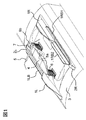
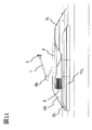
図1〜図4は、本発明による移動車両用遮音装置の第1の実施形態を示す図であって、それぞれ斜視図、正面図、左側面図及び右側面図である。軌道上を走行する鉄道車両のような移動車両は複数の車両を連結して編成をなしており、複数の車両のうち特定の車両の屋根3上に屋根上設置機器の一つである集電装置を設置している。図1〜図4に示すように、移動車両の屋根3上には集電装置が設置される。集電装置は、主に車両の屋根3に固定した碍子6、碍子6に支持された台枠4、架線に接触して架線から集電を行う集電用舟体5、当該集電用舟体5を先端で軸支するアーム7、及びヒンジ8a,8bから構成されている。アーム7は、台枠4に対して車体幅方向と平行な回動軸線を持つヒンジ8aによって軸支されており、ヒンジ8aとアーム7の中間関節部に設けられたヒンジ8bとの関節機能によって、下方へ折り畳んで集電用舟体5を非作動位置に納めることができ、又は上方へ跳ね上げて集電位置を取ることができる。
1 to 4 are views showing a first embodiment of a sound insulation device for a moving vehicle according to the present invention, and are a perspective view, a front view, a left side view, and a right side view, respectively. A moving vehicle such as a railway vehicle traveling on a track is formed by connecting a plurality of vehicles, and is a current collector that is one of the rooftop installation devices on the
碍子6は車体幅方向の中心位置から片方に向かって所定の距離オフセットした位置にあるが、それに対応して集電用舟体5の左右中心位置並びにアーム7及びヒンジ8a,8bの配設位置は車体幅方向のほぼ中心位置にある。なお、集電装置の集電用舟体5は、同じ編成列車の別の集電装置に対して電気的に接続されている。したがって、集電用舟体5を非作動位置に納めた状態でも、当該別の集電装置が集電していれば、集電用舟体5は当該別の集電装置の集電用舟体と同じ電位に帯電している。
The
車両の屋根3上には、集電装置を車体幅方向に挟んで対向する位置に遮音体が設置される。遮音体は、集電装置の車両進行方向左側においては、主となる遮音体1L及びこれより背の低い遮音体2Lから構成されている。遮音体1L及び遮音体2Lは車体幅方向の同じ位置に配置されており、車体長手方向に連続した壁体が分割されて配置されている。一方、集電装置の車両進行方向右側においては、遮音体は、背の高い主となる遮音体1Rと背の低い遮音体2Rとから構成されている。遮音体1R及び遮音体2Rは車体幅方向の同じ位置に配置されており、車体長手方向に連続した壁体が分割されて配置されている。
On the
車両進行方向の一方の碍子6に対向する部分に遮音体1Lが設けられ、また、別の碍子6に対向する部分に遮音体1Rが設けられている。これら遮音体1L及び遮音体1Rは、車両進行方向に沿って山形に形成された壁体であり、その頂上部までの高さは、ほぼ碍子6の高さ寸法と同等の高さとなっている。そして、車体長手方向の並びは遮音体1L及び遮音体2Lと逆になっており、遮音体1Lと遮音体1Rとは、側面から見て、車両進行方向に重複しない、云い代えれば車両進行方向に実質的に重なることなく設置されている。側面から見るとき、遮音体1Lは遮音体2Rと対向し、遮音体1Rは遮音体2Lと対向して配置されている。
A
上記構成の遮音装置を設置した車両が走行すると、走行風により、屋根上機器の一つである集電装置の舟体5、碍子6、アーム7などから騒音が発生するが、本遮音体の構成によってこれら騒音の遮音が図られている。即ち、車両が移動することによって集電装置の騒音源が車両進行方向に対して相対的に後方へ移動するが、遮音体1Lと遮音体1Rの互い違いの設置により、例えば左側に設置した遮音体1Lが右側に設置した遮音体1Rに対して車両進行方向の後方へ変位しているので、集電用舟体5,集電装置碍子6,集電装置アーム7からの騒音を、車両進行方向に対して左側にいる騒音の観測者(あるいは居住地域)に対して効率良く遮音することができる。また、ほぼ碍子6の高さ程度の高さの山形の遮音体1Lと遮音体1Rを互い違いに設置したことにより、アーム7が折り畳まれて非集電位置を占める集電用舟体5に対して遮音体1Lと遮音体1Rは山形の裾近傍が対向することになるので、切欠きを設けることなく十分に絶縁距離を確保することができる。また、同程度の高さの遮音体1Lと遮音体1Rを互い違いに設置することで、遮音体1Lと遮音体1R間での流速の増加が起こらず、集電装置からの空力騒音の増加を防ぐことができると共に、遮音体1Lと遮音体1Rを在来線の車両限界範囲内に納めることができ、更に、走行風に曝される部分が相対的に小さくなり、遮音体1Lと遮音体1Rから発生する空力騒音を小さく抑えることができる。以上より本実施の形態によれば、構成が単純な遮音体1Lと遮音体1Rの設置により、遮音効果を高めることができると共に、在来線区間の車両限界範囲内における最大高さの遮音体を用いても絶縁距離を確保することができ、かつ遮音効果を得ることができる。
When a vehicle equipped with the sound insulation device having the above configuration travels, noise is generated from the
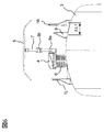
図1〜図2に特に示すように、車体幅方向一側(左側)において屋根3上に設けられた背の低い遮音体2Lは、車両の幅方向外側に枝分かれした遮音体1LBを備えている。
このときの遮音体の配置関係については、図2に示すように、立設された遮音体1L,2L(図中では位置関係から図示されず)と、遮音体2Lから車体両幅方向外側に枝分かれした遮音体1LBとの配置となっている。また、車体幅方向他側(右側)において屋根3上に設けられた背の低い遮音体2Rは、車体幅方向外側に枝分かれした遮音体1RB1及び幅方向内側に枝分かれした遮音体1RB2を備えている。このときの遮音体の配置関係については、図2に示すように、立設する遮音体1R及び遮音体2Rと、遮音体2Rから枝分かれした遮音体1RB1及び遮音体1RB2との配置となっている。
As shown particularly in FIGS. 1 to 2, the short sound insulation body 2 </ b> L provided on the
As shown in FIG. 2, the arrangement relationship of the sound insulators at this time is as follows. It is arranged with the branched sound insulation 1LB. Further, the short
図3には本構成を左から見た図を示す。集電装置の左側に設置される遮音体は、背の高い遮音体1L及び背の低い遮音体2L、並びに遮音体2Lから枝分かれした遮音体1LBから構成されている。立設した遮音体1L及び遮音体2Lに対して枝分かれ遮音体1LBは側方から見てその一部が重なるように配置されている。
FIG. 3 shows a view of this configuration from the left. The sound insulator installed on the left side of the current collector is composed of a
図4には本構成を右から見た図を示す。集電装置右側に設置される遮音体は、背の高い遮音体1R及び背の低い遮音体2R、並びに遮音体2Rから外側に枝分かれした遮音体1RB1及び内側に枝分かれした遮音体1RB2から構成される。枝分かれした遮音体1RB1及び遮音体1RB2は、それぞれ立設した遮音体1R及び遮音体2Rに対して、側方から見て一部の面積が重なるように配置されている。
FIG. 4 shows a diagram of this configuration viewed from the right. The sound insulator installed on the right side of the current collector is composed of a
枝分かれした遮音体1LB、1RB1及び遮音体1RB2は、それぞれ遮音体2L、遮音体2Rの上辺から斜め上方に向かって延びている。また、図1及び図3に示すように、遮音体2Lから枝分かれした遮音体1LBは、遮音体1Lの長手方向中程の位置にまでに跨がって車体長手方向に延びている。また、図1及び図4に示すように、遮音体2Rから枝分かれした遮音体1RB1は、遮音体1Rの長手方向中程の位置にまで跨がって車体長手方向に延びている。主遮音体と、枝分かれした遮音体を持つ遮音体により、集電装置とその周辺から発生した空力騒音は、その直接音を遮るとともに、反射音や回折音についても、屋根3の上から車体外側に伝播するのを効果的に妨げて、遮音を向上させることができる。
The branched sound insulators 1LB and 1RB1 and the sound insulator 1RB2 extend obliquely upward from the upper sides of the
枝分かれした遮音体1LB、遮音体1RB1及び遮音体1RB2は在来線区間における車両限界及び集電装置の絶縁離隔に干渉しない位置に配置される。集電装置が車両中心に対して図2に示すような左寄りに設置されるため、左側の遮音体では集電装置の絶縁離隔の関係から、遮音体2Rに内側に枝分かれする遮音体を設けることはできないこともあるが、車両限界及び集電装置の絶縁離隔の観点から余裕があれば内側に設けてもよく、車体幅方向両側に設けてもよい。また、右側の遮音体から枝分かれする遮音体1RB1又は1RB2についても、どちらか片方だけでも効果が認められる。なお、実測結果からすると、車体幅方向外側に設けるときの遮音効果が大きいことが認められる。更に、枝分かれする遮音体については、背の低い遮音体に設け、背の高い遮音体に途中まで延びる例を示したが、背の高い遮音体の全長まで延ばしても良い。
The branched sound insulation body 1LB, sound insulation body 1RB1, and sound insulation body 1RB2 are arranged at positions that do not interfere with the vehicle limit and the insulation separation of the current collector in the conventional line section. Since the current collector is installed on the left side as shown in FIG. 2 with respect to the center of the vehicle, the sound insulator on the left side is provided with a sound insulator that branches inward in the
本実施例は、このような構成とすることで、構成が簡単で遮音効果が高く、在来線区間の車両限界範囲内に収まり、遮音体と集電装置との間に絶縁離隔を十分に確保することができる。また、遮音体(遮音壁) のみを設置することで、車体断面積を増加させることなく、集電装置やその他の屋根上に設置される機器の騒音の遮音効果を得ることができる。また、在来線区間での車両限界範囲を考慮して、遮音体の高さは従来の遮音体に比べて低く設定されている。また、遮音体と集電装置のホーンや碍子との間での地絡を防止するために、遮音体と集電装置と間にも絶縁離隔が確保されている。更に、枝分かれした遮音体によって、直接音のみならず、対向する遮音体からの反射音や遮音体を回り込む回折音についても車両外側へ伝播するのを抑制することができる。 In this embodiment, the configuration is simple and the sound insulation effect is high, and it is within the vehicle limit range of the conventional line section, and the insulation separation between the sound insulation body and the current collector is sufficiently provided. Can be secured. In addition, by installing only the sound insulator (sound insulation wall), it is possible to obtain a sound insulation effect for noise of the current collector and other devices installed on the roof without increasing the vehicle cross-sectional area. Further, in consideration of the vehicle limit range in the conventional line section, the height of the sound insulator is set lower than that of the conventional sound insulator. Further, in order to prevent a ground fault between the sound insulator and the horn or insulator of the current collector, an insulation separation is also ensured between the sound insulator and the current collector. Further, the branched sound insulators can suppress not only the direct sound but also the reflected sound from the opposing sound insulators and the diffracted sound that surrounds the sound insulators from propagating to the outside of the vehicle.
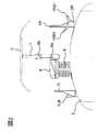
本発明の実施例2を図5〜図8を用いて説明する。図5〜図8は、本発明による移動車両用遮音装置の実施例2を示す図であって、それぞれ斜視図、正面図、左側面図及び右側面図である。実施例2は、実施例1と同等の機能を奏する部材については同じ符号を付すことで再度の詳細な説明を省略する。本実施例2においても、移動車両の屋根3には、設置された集電装置を挟んで対向する形で遮音体が設置される。車体幅方向一側(左側)においては、屋根3上に主となる遮音体1L及びこれより背の低い遮音体2Lが実施例1と同様の形態で配設されるが、遮音体2Lには枝分かれする遮音体が設けられていない。一方、車体幅方向他側(右側)においては、屋根3上に主となる遮音体1R及びこれより背の低い遮音体2Rが実施例1と同様の形態で配設されるが、遮音体2Rには枝分かれする遮音体が設けられていない。
A second embodiment of the present invention will be described with reference to FIGS. FIGS. 5-8 is a figure which shows Example 2 of the sound insulation apparatus for moving vehicles by this invention, Comprising: It is a perspective view, a front view, a left side view, and a right side view, respectively. In the second embodiment, members having the same functions as those in the first embodiment are denoted by the same reference numerals, and detailed description thereof is omitted. Also in the second embodiment, the sound insulator is installed on the
図6には本実施例の正面図を示す。図6にも示されているように、遮音体は集電装置を挟んで車体幅方向両側に設置される。本実施例では、車体幅方向他側(右側)において、遮音体1R及び遮音体2R(図6には図示されず)と集電装置との間に副遮音体9が配設されている。副遮音体9は、遮音体1Rの高さよりも低いが遮音体2Rの高さよりも高いほぼ碍子6の高さを有していて、全体的な形状としては遮音体1Rと同様な山形形状を有している。遮音体1R及び遮音体2Rの後流の影響を受ける位置に副遮音体9を設置すると、空力騒音が発生するため、副遮音体9は、遮音体2Rの車体幅方向内側の位置に、遮音体2Rと平行ではあるが、遮音体1R及び遮音体2Rの車体幅方向厚さに対して2倍程度の間隔(ΔL1)を保って設置されている。本実施例の構成では、集電装置が車両中心に対して左側にオフセットして設置されているため、副遮音体9の設置位置は集電装置の高電圧部に対して絶縁離隔を確保した位置となっている。一方、集電装置と遮音体1L及び遮音体2Lの間では、アーム7を折り畳んだ状態で集電用舟体5との絶縁離隔の関係から、副遮音体を設置することはできない。
FIG. 6 shows a front view of this embodiment. As shown in FIG. 6, the sound insulators are installed on both sides in the vehicle body width direction with the current collector interposed therebetween. In the present embodiment, on the other side (right side) in the vehicle body width direction, the
図7には本構成を左から見た図を、図8には本構成を右から見た図を示す。特に図8に示すように、副遮音体9は、右側の遮音体1R及び遮音体2Rに対してずれた位置に配置され、このとき側方からみて遮音体1R及び遮音体2Rに対して副遮音体9はその一部面積が重なるように配置される。遮音体1Rと副遮音体9とが車体長手方向に重なる範囲がΔL2で示されている。この範囲ΔL2は、遮音体1Rと副遮音体9との山形状の裾部分での重なりであるので、高さは低くなっており、アーム7を折り畳んだときの集電用舟体5に対して絶縁離隔を確保することができる。
FIG. 7 shows a view of the present configuration from the left, and FIG. 8 shows a view of the present configuration from the right. In particular, as shown in FIG. 8, the
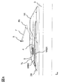
本発明の実施例3を図9〜図12を用いて説明する。図9〜図12は、本発明による移動車両用遮音装置の実施例3を示す図であって、それぞれ斜視図、正面図、左側面図及び右側面図である。実施例3は、実施例1と同等の機能を奏する部材については同じ符号を付すことで再度の詳細な説明を省略する。本実施例3においても、移動車両の屋根3には、設置された集電装置を挟んで対向する形で遮音体が設置される。本実施例3においては、図9に示すように、左側の遮音体1L及び遮音体2Lの車体幅方向外側に副遮音体10Lが配設されており、右側の遮音体1R及び遮音体2Rの車体幅方向外側に副遮音体10Rが配設されている。
A third embodiment of the present invention will be described with reference to FIGS. FIGS. 9-12 is a figure which shows Example 3 of the sound insulation apparatus for moving vehicles by this invention, Comprising: It is a perspective view, a front view, a left view, and a right view, respectively. In the third embodiment, members having the same functions as those of the first embodiment are denoted by the same reference numerals, and detailed description thereof is omitted. Also in the third embodiment, the sound insulator is installed on the
図10には本構成の正面図を示す。図10にも示すように、遮音体1R,2R及び遮音体1L,2Lは集電装置を挟んで車体幅方向両側に設置される。本実施例では、集電装置の右側に設置される遮音体1R及び遮音体2Rの車体幅方向外側に副遮音体10Rが、一方、集電装置の左側に設置される遮音体1L及び遮音体2Lの外側に副遮音体10Lが設置される。副遮音体10L,10Rの高さレベルは、それぞれ、遮音体2Lや遮音体2Rの高さと同程度の高さレベルにあり、全体的な形状としては車体長手方向の両端が遮音体2Lや遮音体2Rの端部と同様な形状を有する低い山形形状を有している。実施例2の場合と同様に、遮音体と副遮音体の間隔が小さい場合には空力騒音が発生する可能性があるため、副遮音体10L,10Rは、遮音体2L,2Rの車体幅方向外側の位置に、遮音体2L,2Rと平行ではあるが、遮音体1R及び遮音体2Rの車体幅方向厚さに対しておおむね2倍程度の間隔を保って設置されている。副遮音体10L,10Rは、車体長手方向には、遮音体1L及び遮音体2Lの中程の位置に対応する位置まで、車体長手方向に延びている。副遮音体10L,10Rの設置位置は、遮音体1L,2L及び遮音体1R,2Rの車体幅方向外側に配設されているので、在来線区間での車両限界範囲内に納まるような形状に制限されているが、集電装置の高電圧部に対しては自ずと絶縁離隔を確保された位置となっている。
FIG. 10 shows a front view of this configuration. As shown in FIG. 10, the
図11には本構成を左から見た図を、図12には本構成を右から見た図を示す。特に,図11に示すように、副遮音体10Lは、左側の遮音体1L及び遮音体2Lに対して、側方から見ると概ね、遮音体1L及び遮音体2Lが遮蔽する範囲内に入っているが、図12に示すように、副遮音体10Rは、右側の遮音体1R及び遮音体2Rに対しては、高さレベルが遮音体2Rのレベルよりも若干高くなっており、このとき側方からみて遮音体1R及び遮音体2Rが重なり合う裾部(実施例2の図8に示す範囲ΔL2)の上方の開いたスペースを覆うように配置される。副遮音体10Rは、このスペースを通しての騒音漏れを防止するのに貢献する。副遮音体10Rは右側の遮音体1R及び遮音体2Rの車体幅方向外側に配置されているので、集電装置のアーム7を折り畳んだときの集電用舟体5に対して絶縁離隔を確保することができる。
FIG. 11 shows a view of the present configuration from the left, and FIG. 12 shows a view of the present configuration from the right. In particular, as shown in FIG. 11, the
本発明は移動車両として、鉄道車両を例に採って説明したが、これに限ることなく、高速で走行して、集電装置等の屋根に設けた機器から騒音を出す車両に適用することができる。また、副遮音体9と副遮音体10L,10Rとについては区別して説明したが、スペース等の各制約が満たされるのであれば、両方の副遮音体を備えていてもよい。
The present invention has been described by taking a railway vehicle as an example of a moving vehicle. However, the present invention is not limited to this, and can be applied to a vehicle that travels at high speed and generates noise from a device provided on a roof such as a current collector. it can. Further, the sub
1L,1R 遮音体
1LB,1RB1,1RB2 枝分かれした遮音体
2L,2R 遮音体
3 屋根 4 台枠
5 集電用舟体 6 碍子
7 アーム 8a,8b ヒンジ
9,10L,10R 副遮音体
ΔL2 重なり範囲
1L, 1R Sound insulation body 1LB, 1RB1, 1RB2 Branched
Claims (2)
前記機器とその周辺で生じた騒音が前記遮音体で回折又は反射した騒音が伝播するのを抑制するため、前記遮音体に対して、車体幅方向の外側と内側との少なくとも一方又両方に向かって車体の長手方向からの投影で見た場合に斜め上方に向かって枝分かれした遮音体が設けられており、
前記屋根に立設された遮音体は車体長手方向に山形の形状を有するとともに、車体長手方向に背の高い山形の遮音体と背の低い山形の遮音体とが連続して配置された壁体であり、
前記枝分かれした遮音体は、前記車体長手方向に山形の形状を有する羽根状の遮音体であるとともに、前記背の低い遮音体に設けられており、且つ車体長手方向に、前記背の高い遮音体の一部又は全部に対応する位置にまで跨がって延びており、前記遮音体及び前記枝分かれした遮音体により、前記騒音が車体の外側へ伝播するのを抑制すること
を特徴とする移動車両用遮音装置。 In a sound insulation device for a moving vehicle comprising a sound insulation body standing on the roof opposite to both sides in the vehicle body width direction with respect to equipment installed on the roof of the vehicle body,
Since the noise noise generated in and around the device is diffracted or reflected by the sound insulating member is prevented from propagating, it said for the sound insulating member, toward the at least one addition both the outside and inside of the vehicle body width direction When viewed from the longitudinal direction of the vehicle body, a sound insulator is provided that branches off obliquely upward .
The sound insulation body erected on the roof has a mountain shape in the longitudinal direction of the vehicle body, and a wall body in which a tall mountain-shaped sound insulation body and a short mountain-shaped sound insulation body are continuously arranged in the vehicle body longitudinal direction. And
The branched sound insulation body, the vehicle body longitudinal direction chevron vane shaped sound insulating member der Rutotomoni having a shape, is provided on the back of lower sound insulating member, and in the longitudinal direction of the car body, high the back sound insulation A movement characterized by extending over a position corresponding to a part or all of the body and suppressing the noise from propagating to the outside of the vehicle body by the sound insulation body and the branched sound insulation body. A sound insulation device for a vehicle.
前記枝分かれした前記遮音体は、車体の外形に求められる車両限界及び集電装置の高電圧部からの絶縁離隔を確保していること
を特徴とする移動車両用遮音装置。
The sound insulation device for a moving vehicle according to claim 1 ,
The sound insulation for mobile vehicles is characterized in that the branched sound insulation has a vehicle limit required for an outer shape of a vehicle body and an insulation separation from a high voltage portion of a current collector.
Priority Applications (4)
| Application Number | Priority Date | Filing Date | Title |
|---|---|---|---|
| JP2011121706A JP6185219B2 (en) | 2011-05-31 | 2011-05-31 | Sound insulation device for moving vehicles |
| PCT/JP2012/063483 WO2012165331A1 (en) | 2011-05-31 | 2012-05-25 | Acoustic insulation device for mobile vehicle |
| US14/123,132 US9227577B2 (en) | 2011-05-31 | 2012-05-25 | Acoustic insulation device for mobile vehicle |
| GB1321016.6A GB2505795B (en) | 2011-05-31 | 2012-05-25 | Acoustic insulation device for mobile vehicle |
Applications Claiming Priority (1)
| Application Number | Priority Date | Filing Date | Title |
|---|---|---|---|
| JP2011121706A JP6185219B2 (en) | 2011-05-31 | 2011-05-31 | Sound insulation device for moving vehicles |
Publications (3)
| Publication Number | Publication Date |
|---|---|
| JP2012249493A JP2012249493A (en) | 2012-12-13 |
| JP2012249493A5 JP2012249493A5 (en) | 2014-06-05 |
| JP6185219B2 true JP6185219B2 (en) | 2017-08-23 |
Family
ID=47259188
Family Applications (1)
| Application Number | Title | Priority Date | Filing Date |
|---|---|---|---|
| JP2011121706A Active JP6185219B2 (en) | 2011-05-31 | 2011-05-31 | Sound insulation device for moving vehicles |
Country Status (4)
| Country | Link |
|---|---|
| US (1) | US9227577B2 (en) |
| JP (1) | JP6185219B2 (en) |
| GB (1) | GB2505795B (en) |
| WO (1) | WO2012165331A1 (en) |
Families Citing this family (4)
| Publication number | Priority date | Publication date | Assignee | Title |
|---|---|---|---|---|
| DE102012202955A1 (en) * | 2012-02-27 | 2013-08-29 | Schunk Bahn- Und Industrietechnik Gmbh | Power transmission device for charging electrical energy storage of vehicles at overhead charging stations |
| CN104149632B (en) * | 2014-08-19 | 2016-03-16 | 安徽理工大学 | Three-freedom-degree hybrid vibration damping pantograph |
| CN110126625B (en) * | 2019-05-16 | 2021-08-31 | 大连交通大学 | Novel high-speed pantograph and lightweight dynamic design method thereof |
| CN110182148B (en) * | 2019-06-10 | 2022-08-23 | 惠州市惠福鞋材有限公司 | Sound-insulation EVA (ethylene-vinyl acetate) plate for automobile |
Family Cites Families (12)
| Publication number | Priority date | Publication date | Assignee | Title |
|---|---|---|---|---|
| JP2938159B2 (en) | 1990-07-20 | 1999-08-23 | 三井化学株式会社 | Continuous production method of high gloss impact resistant rubber modified resin |
| JPH0742163Y2 (en) * | 1990-11-20 | 1995-09-27 | 西日本旅客鉄道株式会社 | Noise prevention structure for train rooftop equipment |
| JPH0577729A (en) * | 1991-03-29 | 1993-03-30 | Hitachi Ltd | Noise insulating device for rolling stock car |
| JP2865275B2 (en) * | 1994-07-20 | 1999-03-08 | 株式会社ブリヂストン | Noise barrier |
| JP3069828B2 (en) * | 1994-09-16 | 2000-07-24 | 西日本旅客鉄道株式会社 | Windproof cover of current collector |
| JP4300543B2 (en) * | 1999-07-19 | 2009-07-22 | ビーバ株式会社 | Silencer |
| JP2003219505A (en) * | 2002-01-22 | 2003-07-31 | Central Japan Railway Co | Noise-absorbing sidewall structure for pantograph cover device |
| JP3908214B2 (en) * | 2003-10-28 | 2007-04-25 | 近畿車輌株式会社 | Soundproof side wall of current collector |
| JP4286759B2 (en) * | 2004-10-01 | 2009-07-01 | 東海旅客鉄道株式会社 | Cover device for vehicle roof projections |
| JP2006159938A (en) * | 2004-12-02 | 2006-06-22 | East Japan Railway Co | Sound insulating board of current collector for vehicle |
| JP5189374B2 (en) * | 2008-01-31 | 2013-04-24 | 株式会社日立製作所 | Sound insulation device for moving vehicles |
| JP5215708B2 (en) * | 2008-03-31 | 2013-06-19 | 株式会社日立製作所 | Soundproof side wall for current collector and railcar equipped with the same |
-
2011
- 2011-05-31 JP JP2011121706A patent/JP6185219B2/en active Active
-
2012
- 2012-05-25 WO PCT/JP2012/063483 patent/WO2012165331A1/en active Application Filing
- 2012-05-25 GB GB1321016.6A patent/GB2505795B/en not_active Expired - Fee Related
- 2012-05-25 US US14/123,132 patent/US9227577B2/en active Active
Also Published As
| Publication number | Publication date |
|---|---|
| GB2505795B (en) | 2017-03-15 |
| GB2505795A (en) | 2014-03-12 |
| GB201321016D0 (en) | 2014-01-15 |
| WO2012165331A1 (en) | 2012-12-06 |
| US20140203596A1 (en) | 2014-07-24 |
| JP2012249493A (en) | 2012-12-13 |
| US9227577B2 (en) | 2016-01-05 |
Similar Documents
| Publication | Publication Date | Title |
|---|---|---|
| JP6185219B2 (en) | Sound insulation device for moving vehicles | |
| WO2017194765A1 (en) | Low-electromagnetic radiation electric motor vehicle | |
| Kurita et al. | Reduction of pantograph noise of high-speed trains | |
| JP5189374B2 (en) | Sound insulation device for moving vehicles | |
| JP4613815B2 (en) | Noise barrier for railway vehicles | |
| JP3374469B2 (en) | Current collector | |
| JP2012249493A5 (en) | ||
| JP2004132062A (en) | Sound insulation wall for railways | |
| JPH06245309A (en) | Current collector and vehicle mounting the same | |
| JP3069828B2 (en) | Windproof cover of current collector | |
| JP4430880B2 (en) | Projection for electrostatic antenna of high-speed traveling vehicle | |
| JP6831761B2 (en) | Noise reduction device | |
| JPH0742163Y2 (en) | Noise prevention structure for train rooftop equipment | |
| JP2005030116A (en) | Visible soundproof wall for moving sound source and soundproof unit | |
| JP3678949B2 (en) | Visible noise barrier for mobile sound source | |
| JP4329051B2 (en) | Windproof cover for current collector | |
| JP2006159938A (en) | Sound insulating board of current collector for vehicle | |
| JP2021000943A (en) | Noise insulating device for railway vehicle | |
| JP5827744B2 (en) | Pantograph device | |
| CN211571356U (en) | Damping type low-noise trough beam of high-speed railway | |
| JP6927755B2 (en) | Railroad vehicle | |
| JPH0577729A (en) | Noise insulating device for rolling stock car | |
| JP2000278803A (en) | Pantagraph with cover | |
| JPH03155302A (en) | Sound insulator for pantograph | |
| JPH03155303A (en) | Noise insulator for pantograph |
Legal Events
| Date | Code | Title | Description |
|---|---|---|---|
| A521 | Request for written amendment filed |
Free format text: JAPANESE INTERMEDIATE CODE: A523 Effective date: 20140418 |
|
| A621 | Written request for application examination |
Free format text: JAPANESE INTERMEDIATE CODE: A621 Effective date: 20140418 |
|
| A131 | Notification of reasons for refusal |
Free format text: JAPANESE INTERMEDIATE CODE: A131 Effective date: 20150331 |
|
| A521 | Request for written amendment filed |
Free format text: JAPANESE INTERMEDIATE CODE: A523 Effective date: 20150521 |
|
| A131 | Notification of reasons for refusal |
Free format text: JAPANESE INTERMEDIATE CODE: A131 Effective date: 20151006 |
|
| A521 | Request for written amendment filed |
Free format text: JAPANESE INTERMEDIATE CODE: A523 Effective date: 20151111 |
|
| A02 | Decision of refusal |
Free format text: JAPANESE INTERMEDIATE CODE: A02 Effective date: 20160510 |
|
| A521 | Request for written amendment filed |
Free format text: JAPANESE INTERMEDIATE CODE: A821 Effective date: 20160722 |
|
| A521 | Request for written amendment filed |
Free format text: JAPANESE INTERMEDIATE CODE: A523 Effective date: 20170615 |
|
| A61 | First payment of annual fees (during grant procedure) |
Free format text: JAPANESE INTERMEDIATE CODE: A61 Effective date: 20170727 |
|
| R150 | Certificate of patent or registration of utility model |
Ref document number: 6185219 Country of ref document: JP Free format text: JAPANESE INTERMEDIATE CODE: R150 |