JP6183846B2 - Refill container stopper - Google Patents
Refill container stopper Download PDFInfo
- Publication number
- JP6183846B2 JP6183846B2 JP2013246319A JP2013246319A JP6183846B2 JP 6183846 B2 JP6183846 B2 JP 6183846B2 JP 2013246319 A JP2013246319 A JP 2013246319A JP 2013246319 A JP2013246319 A JP 2013246319A JP 6183846 B2 JP6183846 B2 JP 6183846B2
- Authority
- JP
- Japan
- Prior art keywords
- refill container
- plug
- outflow
- refill
- stopper
- Prior art date
- Legal status (The legal status is an assumption and is not a legal conclusion. Google has not performed a legal analysis and makes no representation as to the accuracy of the status listed.)
- Active
Links
- 230000002093 peripheral effect Effects 0.000 claims description 83
- 238000003780 insertion Methods 0.000 claims description 21
- 230000037431 insertion Effects 0.000 claims description 21
- 239000000463 material Substances 0.000 claims description 4
- 230000005484 gravity Effects 0.000 claims description 3
- 238000000034 method Methods 0.000 claims 2
- 239000007788 liquid Substances 0.000 description 18
- 230000000903 blocking effect Effects 0.000 description 8
- 238000012937 correction Methods 0.000 description 4
- 239000003599 detergent Substances 0.000 description 3
- 230000000694 effects Effects 0.000 description 3
- 230000005021 gait Effects 0.000 description 2
- 239000005022 packaging material Substances 0.000 description 2
- -1 polypropylene Polymers 0.000 description 2
- 229920003002 synthetic resin Polymers 0.000 description 2
- 239000000057 synthetic resin Substances 0.000 description 2
- 239000004698 Polyethylene Substances 0.000 description 1
- 239000004743 Polypropylene Substances 0.000 description 1
- 229920000704 biodegradable plastic Polymers 0.000 description 1
- 239000002131 composite material Substances 0.000 description 1
- 238000011161 development Methods 0.000 description 1
- 238000005516 engineering process Methods 0.000 description 1
- 230000007613 environmental effect Effects 0.000 description 1
- 239000012530 fluid Substances 0.000 description 1
- 235000013305 food Nutrition 0.000 description 1
- 230000002401 inhibitory effect Effects 0.000 description 1
- 238000001746 injection moulding Methods 0.000 description 1
- 235000013372 meat Nutrition 0.000 description 1
- 238000012986 modification Methods 0.000 description 1
- 230000004048 modification Effects 0.000 description 1
- 229920000747 poly(lactic acid) Polymers 0.000 description 1
- 229920000573 polyethylene Polymers 0.000 description 1
- 239000004626 polylactic acid Substances 0.000 description 1
- 229920001155 polypropylene Polymers 0.000 description 1
- 239000000843 powder Substances 0.000 description 1
- 229920005989 resin Polymers 0.000 description 1
- 239000011347 resin Substances 0.000 description 1
- 230000008719 thickening Effects 0.000 description 1
Images


Landscapes
- Closures For Containers (AREA)
Description
本発明は、詰替え容器用栓体に関し、特に、被詰替え容器に内容物を詰め替えるための、詰替え容器の詰替え流出口を覆って取り付けられる詰替え容器用栓体に関する。 The present invention relates to a plug for a refill container, and more particularly, to a plug for a refill container that is attached to cover the refill outlet of the refill container for refilling the contents of the refill container.
近年、各種の液体や、その他の内容物を収納する合成樹脂製の容器についても、環境負荷の低減が図られるようになっており、使用する樹脂量を減らした薄肉の容器が種々開発されている。また、各種の洗剤や食品等を収納する容器として、パウチ等による詰替え容器が多く用いられている。詰替え容器は、収納した内容物を、吐出ノズル部や注出部を備える被詰替え容器に詰め替えたり補充したりすることで、高価な被詰替え容器をその都度廃棄することなく、長期間使用できるようにする。 In recent years, with regard to synthetic resin containers that contain various liquids and other contents, it has become possible to reduce the environmental burden, and various thin-walled containers have been developed that reduce the amount of resin used. Yes. In addition, refill containers such as pouches are often used as containers for storing various detergents and foods. The refill container can be refilled or refilled with a refilled container equipped with a discharge nozzle and a pour-out unit, so that an expensive refill container can be used for a long time without being discarded each time. Make it available.
一方、パウチ等による詰替え容器は、柔軟性や可撓性に富んだ軟包材によって形成されており、詰め替え作業の際に容器が変形し易く、きわめて不安定な状態となり易い。また、詰替え容器による内容物の詰め替え作業は、例えば、a)ノズル部の先端を切断する、b)傾けて注ぐ、c)傾けた状態を保持する、d)絞る、e)こぼれないように注意しつつ廃棄する、といった作業ステップによって行われるが、これらの作業ステップによる内容物の詰め替え作業は、多くの手間を要することになると共に、作業中に内容物をこぼし易い。 On the other hand, a refill container such as a pouch is formed of a soft packaging material that is rich in flexibility and flexibility, and the container is likely to be deformed during refilling work, and is likely to be extremely unstable. In addition, the refilling operation of the contents by the refill container can be performed by, for example, a) cutting the tip of the nozzle part, b) pouring at an angle, c) holding the tilted state, d) squeezing, e) not spilling. Although it is carried out by work steps such as discarding with care, refilling the contents by these work steps is time consuming and easily spills the contents during the work.
このようなことから、軟包材によって形成された容器の詰替え流出口を被詰替え容器の口首部に確実に連結して、詰め替え易さを向上させた詰替え容器が提案されている(例えば、特許文献1、特許文献2参照)。特許文献1の詰替え容器では、詰替え流出口に、内周面に雌ねじが形成された筒部を有する栓体が取り付けられており、被詰替え容器の口首部の外周面に形成された雄ねじに、筒部の雌ねじを螺合して、被詰替え容器の口首部に詰替え容器の詰替え流出口を連結するようになっている。 For this reason, a refill container has been proposed in which the refill outlet of the container formed of the soft wrapping material is securely connected to the mouth portion of the refill container to improve refillability ( For example, see Patent Document 1 and Patent Document 2). In the refill container of Patent Document 1, a plug body having a cylindrical portion with an internal thread formed on the inner peripheral surface is attached to the refill outlet, and is formed on the outer peripheral surface of the mouth portion of the refill container. The internal thread of the cylinder part is screwed to the external thread, and the refill outlet of the refill container is connected to the neck of the refill container.
しかしながら、特許文献1の詰替え容器では、栓体の筒部の先端開口を覆うキャップやシール部を取り外したり、筒部を被詰替え容器の口首部に螺合する操作を必要とし、作業性に劣ることから、例えばワンアクションの簡易な操作によって、詰替え流出口を被詰替え容器の口首部に容易に且つ確実に連通できるようにすると共に、安定した状態で内容物の詰め替え作業を行えるようにする、新たな技術の開発が望まれている。 However, the refill container of Patent Document 1 requires an operation of removing a cap or a seal part covering the distal end opening of the cylindrical part of the plug body or screwing the cylindrical part to the mouth part of the refilled container. Therefore, the refill outlet can be easily and surely communicated with the mouth of the refill container by a simple one-action operation, and the contents can be refilled in a stable state. Therefore, development of new technology is desired.
特許文献2の詰替え容器では、キャップを開け、挿し込むだけで、詰替え容器を開封でき、容易な操作で詰替え作業を行うことが可能である。一方で、スリット部を開封させる機構のため、開封力を安定にすることが難しい点や更に、複合部材を用いるため、環境面やコスト面に課題がある。 In the refill container of Patent Document 2, it is possible to open the refill container simply by opening the cap and inserting it, and the refill work can be performed with an easy operation. On the other hand, because of the mechanism for opening the slit portion, it is difficult to stabilize the opening force, and furthermore, since a composite member is used, there are problems in terms of environment and cost.
本発明は、詰替え容器に取り付けて用いられ、簡易な操作、及び簡易な力で詰替え容器の詰替え流出口を被詰替え容器の口首部に連通させることができると共に、安定した状態で内容物を被詰替え容器に詰め替えさせることのできる詰替え容器用栓体を提供することを目的とする。 The present invention is used by being attached to a refill container, and allows the refill outlet of the refill container to communicate with the mouth of the refill container with a simple operation and simple force, and in a stable state. An object of the present invention is to provide a plug for a refill container that can refill the contents into a refill container.
本発明は、被詰替え容器に内容物を詰め替えるための、詰替え容器の詰替え流出口を覆って取り付けられる詰替え容器用栓体であって、前記詰替え流出口の開口周縁部分に接合固定される栓本体と、該栓本体の天面板に開口形成された流出開口を流出方向内側から閉塞して、栓本体に着脱可能に装着される栓蓋とからなり、前記栓本体は、前記流出開口を囲んで前記天面板から流出方向外側に突出する流出筒と、前記流出開口を囲んで前記天面板から流出方向内側に突出する装着筒とを備えており、前記栓蓋は、外周面が前記装着筒の内周面に密着する装着壁面部と、前記装着筒の中空断面形状と同様の平面形状を有する閉塞板部と、該閉塞板部の周縁部分から立設する押込み凸部とを備えており、前記押込み凸部を、前記流出開口の開口周縁部に連続して切欠き形成された挿通口、又は前記流出筒に隣接して開口形成された挿通口を介して、前記天面板から前記流出筒に沿って流出方向外側に突出させた状態で、前記栓蓋が前記栓本体に装着されている詰替え容器用栓体を提供することにより、上記目的を達成したものである。 The present invention is a plug for a refill container for refilling the contents to be refilled, covering the refill outlet of the refill container, and is joined to the opening peripheral portion of the refill outlet. The stopper body is fixed, and the outlet opening formed in the top plate of the stopper body is closed from the inside in the outlet direction, and the stopper lid is detachably attached to the stopper body. An outflow tube that surrounds the outflow opening and protrudes outward from the top plate in the outflow direction; and a mounting tube that surrounds the outflow opening and protrudes inward in the outflow direction from the top surface plate. A mounting wall surface portion that is in close contact with the inner peripheral surface of the mounting cylinder, a closing plate portion having a planar shape similar to the hollow cross-sectional shape of the mounting tube, and a pressing convex portion that is erected from a peripheral portion of the closing plate portion; The push-out convex portion has an opening circumference of the outflow opening. In a state of projecting outward from the top plate along the outflow tube through the insertion port formed in the cutout continuously in the part or through the insertion port formed adjacent to the outflow tube. The above object is achieved by providing a plug for a refill container in which the plug lid is mounted on the plug body.
本発明の詰替え容器用栓体によれば、詰替え容器に取り付けて用いられて、簡易な操作、及び簡易な力で詰替え容器の詰替え流出口を被詰替え容器の口首部に連通させることができると共に、安定した状態で内容物を被詰替え容器に詰め替えさせることができる。 According to the plug for a refill container of the present invention, it is used by being attached to the refill container, and the refill outlet of the refill container is communicated with the mouth of the refill container with a simple operation and simple force. In addition, the contents can be refilled in a refill container in a stable state.
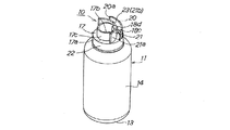
本発明の好ましい第1実施形態に係る詰替え容器用栓体10は、図1〜図3に示すように、詰替え容器11として例えば薄肉のボトル形状の容器の口首部12(図3(a)、(b)参照)に、これの先端開口による詰替え流出口12aを覆って取り付けられる。
As shown in FIGS. 1 to 3, a
また、本第1実施形態の詰替え容器用栓体10は、詰替え流出口12aを封止した状態で詰替え容器11の口首部12に一体として固定されており、詰め替え作業の際に、詰替え容器11の口首部12と共に被詰替え容器15の口首部16に押し込まれることで、好ましくはワンアクションの簡易な操作によって、詰替え流出口12aを被詰替え容器15の口首部16に連通させる機能を備えると共に、詰替え流出口12aから被詰替え容器15に、内容液を外部に漏れ出させることなくスムーズに流入させる機能を備える。
Further, the refill container stopper 10 of the first embodiment is integrally fixed to the
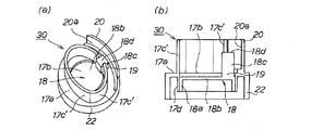
そして、本第1実施形態の詰替え容器用栓体10は、被詰替え容器15に内容物を詰め替えるための、例えば口首部12の先端開口による詰替え流出口12aを覆ってボトル形状の詰替え容器11に取り付けて用いられる栓部材であって、図4(a)、(b)にも示すように、詰替え流出口12aの開口周縁部分に接合固定される栓本体17と、この栓本体17の天面板17aに開口形成された流出開口17bを流出方向内側から閉塞して、栓本体17に着脱可能に装着される栓蓋18とからなる。栓本体17は、流出開口17bを囲んで天面板17aから流出方向外側に突出する流出筒17cと、流出開口17bを囲んで天面板17aから流出方向内側に突出する装着筒17dとを備えており、栓蓋18は、外周面が装着筒17dの内周面に密着する装着壁面部18aと、装着筒17dの中空断面形状と同様の平面形状を有する閉塞板部18bと、閉塞板部18bの周縁部分から立設する押込み凸部18cとを備えている。押込み凸部18cを、流出開口17bの開口周縁部に連続して、好ましくは流出筒17cの径方向外側まで切欠き形成された挿通口19(図5(a)〜(c)参照)を介して、天面板17bから流出筒17cに沿って流出方向外側に突出させ、且つ好ましくは押込み凸部18cの先端面18dの少なくとも一部を、流出筒17cの外周面よりも径方向外側に配置した状態で、栓蓋18が栓本体17に嵌め込まれるようにして装着されている。
The refill container stopper 10 according to the first embodiment covers a
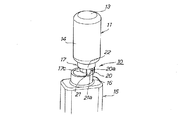
図3(a)、(b)に示すように、内容物を詰め替える際に、好ましくは流出筒17cの外周面を被詰替え容器15の口首部16の内周面に沿わせるようにして、詰替え容器11に取り付けられた当該栓体10を被詰替え容器15に向けて押し込むことで、先端面18dに被詰替え容器15の口首部16の端面部が当接した押込み凸部18cが(図3(a)参照)、詰替え容器11の内部に押し出されて、栓蓋18が装着筒17dから脱落することにより(図3(b)参照)、流出開口17bが開放されて、内容物である例えば液体洗剤等の内容液を、詰替え容器11から被詰替え容器15に流入させるようになっている。
As shown in FIGS. 3 (a) and 3 (b), when refilling the contents, preferably the outer peripheral surface of the
また、本第1実施形態の詰替え容器用栓体10では、図4(a)に示すように、流出筒17cの径方向外側に配置されて、被詰替え容器15の口首部16の外周形状に沿った内周形状部分20aを有するガイト外壁20が、天面板17bから容器11の流出方向外側に突出して栓本体17に設けられている。
In the
さらに、本第1実施形態の詰替え容器用栓体10では、流出筒17cの押込み凸部18cが突出する部分に外接させるようにして、被詰替え容器15の口首部16の内周形状の沿った外周形状部分21aを有するガイト内壁21が、天面板17bから流出方向外側に突出して栓本体17に設けられている。
Furthermore, in the
本第1実施形態の詰替え容器用栓体10は、例えばポリプロピレン、ポリエチレン等の合成樹脂や、ポリ乳酸等のバイオプラスチックを用いた金型成形品であって、図4(a)、(b)に示すように、好ましくは射出成形方法によって、栓本体17と栓蓋18とからなる2パーツの部品として形成されている。
The
詰替え容器用栓体10を構成する栓本体17は、図5(a)〜(c)に示すように、流出開口17bが開口形成された円板形状の天面板17aと、天面板17aの流出方向外側の面である上面から上方に突出して設けられた、略円筒形状の流出筒17cと、天面板17aの流出方向内側の面である下面から下方に突出して設けられた、円筒形状の装着筒17dとを備えており、さらに、ガイト外壁20及びガイト内壁21と、固定スカート部22とを含んで一体成形されている。
As shown in FIGS. 5 (a) to 5 (c), the
固定スカート部22は、円板形状の天面板17aの周縁部から下方に突出して設けられた、円筒形状の部分あって、内周面に雌ネジ突条や係合リブ(図示せず)が形成されている。これらの雌ネジ突条や係合リブを、詰替え容器11の口首部12の外周面に形成された雄ネジ突条や被係合リブ(図示せず)に係合することで、栓本体17が、螺合形式や嵌合形式によって、詰替え容器11の口首部12に装着固定される(図1参照)。
The fixed
本第1実施形態では、天面板17aに開口形成された流出開口17bは、円形の開口となっており、その中心位置が、天面板17aの中心位置から片側にずれた状態で設けられている。天面板17aの中心位置から片側にずれた方向とは反対方向の部分における、流出開口17bの開口周縁部を切り欠くことで、略矩形形状の挿通口19が、当該開口周縁部に連続して形成されている。この挿通口19には、栓蓋18が栓本体17に装着された際に、栓蓋18の押込み凸部18cが挿通される。
In the first embodiment, the
流出筒17cは、本第1実施形態では、天面板17aの上面における円形の流出開口17bの開口周縁部から上方に突出して、中心位置を天面板17aの中心から片側にずらせた状態で、流出開口17bの周囲を囲んで略円筒形状を備えるように設けられている。また流出筒17cは、挿通口19と交差する部分が、分断部23として切り欠かれた状態で設けられている。これによって、挿通口19は、分断部23を介して、流出筒17cの径方向外側にはみ出すように開口形成されている。
In the first embodiment, the
装着筒17dは、本第1実施形態では、円形の流出開口17b及びこれと連続する挿通口19の周囲を一体として環状に囲うと共に、好ましくは天面板17aと同心状に配置されて、天面板17aの下面から下方に突出して略円筒形状を有するように設けられている(図5(c)参照)。これによって、流出筒17cと装着筒17dとは、天面板17aの上面側や下面側に、中心位置をずらせて、異なる大きさの筒形状となるように設けられている。
In the first embodiment, the mounting
本第1実施形態では、さらに、天面板17bから流出方向外側に突出して、ガイト外壁20とガイト内壁21とが設けられている。ガイト外壁20は、本第1実施形態では、被詰替え容器15の口首部16が円筒形状を有していることから(図2参照)、被詰替え容器15の口首部16の外周形状に沿った形状として、円弧状の内周形状部分20aを内周面の全体に備える、円弧状の壁板部分となっている。ガイト外壁20は、流出筒17cの分断部23と近接する部分において、内周面の内周形状部分20aと流出筒17cとの間に、被詰替え容器15の口首部16の肉厚よりも僅かに大きな間隔を保持すると共に、分断部23と近接する部分の両側に、口首部16の外径と略同様の曲率半径で湾曲させた状態で、天面板17bの周縁部分に延設して設けられている。
In the first embodiment, a guide
ガイト外壁20が設けられていることにより、内容物を詰め替える際に、当該ガイト外壁20の内周形状部分20aを被詰替え容器15の口首部16の外周面に沿わせることでガイドさせて、流出筒17cの外周面を被詰替え容器15の口首部16の内周面に沿わせながら詰替え容器用栓体10を被詰替え容器15に向けて押し込む操作を、より安定した状態で行うことが可能になると共に、被詰替え容器15の口首部16の端面部が栓蓋18の押込み凸部18cの先端面18dに確実に当接するように、よりスムーズに案内することが可能になる。
By providing the guide
ガイト内壁21は、本第1実施形態では、被詰替え容器15の口首部16が円筒形状を有していることから(図2参照)、被詰替え容器15の口首部16の内周形状に沿った形状として、円弧状の外周形状部分21aを外周面の全体に備える、円弧状の壁板部分となっている。ガイト内壁21は、流出筒17cの分断部23と重ねて配置される分断部21bによって分断された状態で設けられている。またガイト内壁21は、押込み凸部18cが突出する部分である流出筒17cの分断部23に当該分断部21bを重ねることで、分断部23,21bにおいて流出筒17cに外接するようにして、分断部23,21bから両側に延設して設けられている。さらに、ガイト内壁21は、外周形状部分21aである外周面を、被詰替え容器15の口首部16の内径と略同様の曲率半径で湾曲させた状態で設けられている。これによって、本第1実施形態では、ガイト内壁21の外周形状部分21aと、ガイト外壁20の内周形状部分20aとの間には、被詰替え容器15の口首部16の肉厚よりも僅かに大きな間隔が保持されることになる。
In the first embodiment, since the
ガイト内壁21が設けられていることにより、内容物を詰め替える際に、当該ガイト内壁21の外周形状部分21aを被詰替え容器15の口首部16の内周面に沿わせることでガイドさせて、流出筒17cの外周面を被詰替え容器15の口首部16の内周面に沿わせながら詰替え容器用栓体10を被詰替え容器15に向けて押し込む操作を、より安定した状態で行うことが可能になると共に、被詰替え容器15の口首部16の端面部が栓蓋18の押込み凸部18cの先端面18dに確実に当接するように、よりスムーズに案内することが可能になる。また、ガイト内壁21の外周形状部分21aと、ガイト外壁20の内周形状部分20aとの間に、被詰替え容器15の口首部16の肉厚よりも僅かに大きな間隔が保持されることで、詰替え容器用栓体10を被詰替え容器15に向けて押し込む操作を、さらに安定した状態で行うことが可能になると共に、被詰替え容器15の口首部16の端面部が栓蓋18の押込み凸部18cの先端面18dに確実に当接するように、さらにスムーズに案内することが可能になる。
By providing the guide
詰替え容器用栓体10を構成する栓蓋18は、図4(a)、(b)及び図6に示すように、外周面が栓本体17の装着筒17dの内周面に密着する装着壁面部18aと、装着筒17dの中空断面形状と同様の平面形状を有する閉塞板部18bと、閉塞板部18bの周縁部分から上方に立設する押込み凸部18cとからなる。本第1実施形態では、装着壁面部18aは、円筒形状の装着筒17dの内径と同様の外径を有する、偏平な円筒形状部分18eの外周面によって形成されている。閉塞板部18bは、円筒形状部分18eの流出方向外側の面となる上方の開口端面を覆って一体成形された、円形板状の部分によって形成されている。押込み凸部18cは、円形板状の閉塞板部18bの周縁部分から、流出方向外側である上方に立設して一体成形された、4角柱部分によって形成されている。
As shown in FIGS. 4 (a), 4 (b) and 6, the
栓蓋18は、押込み凸部18c及び閉塞板部18bを流出方向外側に向けて、栓本体17の流出方向内側から、押込み凸部18cを天面板17bに形成された挿通口19に挿通させつつ、栓本体17の装着筒17dに押し込むことで、円筒形状部分18eの外周面による装着壁面部18aを装着筒17dの内周面に強固に密着させた状態で、装着筒17dに嵌め込まれることにより、栓本体17に一体として装着される。またこれによって、栓蓋18は、挿通口19に挿通された押込み凸部18cを、流出筒17cに沿って天面板17bから流出方向外側に突出させ、且つ押込み凸部18cの略4角形の先端面18dにおける略半分の部分を、流出筒17cの外周面よりも径方向外側に配置した状態で、栓本体17に一体として装着される。
The
ここで、本第1実施形態では、栓蓋18は、栓本体17の流出筒17cやガイト内壁21やガイト外壁20の先端よりも低い高さで押込み凸部18cを突出させて、栓本体17に一体として装着されている。押込み凸部18cが、流出筒17c、ガイト内壁21、ガイト外壁20のいずれか1つの先端よりも低い高さで突出していることにより、例えば詰替え容器11の落下等によって、詰替え容器用栓体10の先端が床面等に衝突した際に、衝突時の荷重を流出筒17cやガイト内壁21やガイト外壁20によって受けることで、衝突時の荷重が押込み凸部18cを介して栓蓋18に伝わるのを効果的に回避することが可能になる。これによって、栓蓋18が栓本体17に対して不用意に移動することで、栓蓋18が装着筒17dから外れて、内容液が流出することを効果的に回避することが可能になるとともに、店頭で陳列される際に栓蓋の押込み部分が故意に押されて、誤開封されてしまい、内容液が流出することを効果的に回避することが可能になる。
Here, in the first embodiment, the
また、栓蓋18は、詰替え容器11に収容された詰替え用の内容液よりも、比重の低い材質のものとなっていることが好ましい。栓蓋18が内容液よりも比重の低い材質のものとなっていることにより、内容物を詰め替える際に、詰替え容器11を倒立状態として、詰替え容器用栓体10を被詰替え容器15に向けて押し込むことによって装着筒17dから脱落した後に詰替え容器11の内部に押し出された栓蓋18は、収容された内容液による浮力の作用によって、上方に移動しようとするので、押し出された栓蓋18によって流出開口17bを介した内容液の流出が阻害されるのを、効果的に回避することが可能になる。
Moreover, it is preferable that the
上述の構成を備える本第1実施形態の詰替え容器用栓体10は、栓蓋18を流出方向内側から装着筒17dに装着することにより、流出開口17bを閉塞して栓蓋18が栓本体17に一体として取り付けられた状態で、栓本体17の固定スカート部22を介して詰替え容器11の口首部12に接合固定して用いられる(図1〜図3参照)。
In the refill container plug 10 of the first embodiment having the above-described configuration, the
そして、本第1実施形態の詰替え容器用栓体10によれば、詰替え容器11の口首部12に取り付けて用いられて、簡易な操作、及び簡易な力によって詰替え容器11の口首部12の先端の詰替え流出口12aを、被詰替え容器15の口首部16に連通させることが可能になると共に、安定した状態で内容液を被詰替え容器15に詰め替えさせることが可能になる。
And according to the
すなわち、本第1実施形態によれば、詰替え容器用栓体10は、栓本体17と、栓蓋18とからなり、栓本体17は、流出開口17bを囲んで天面板17aから流出方向外側に突出する流出筒17cと、流出開口17bを囲んで天面板17aから流出方向内側に突出する装着筒17dとを備えており、栓蓋18は、装着筒17dの内周面に密着する装着壁面部18aと、閉塞板部18bと、閉塞板部18bから立設する押込み凸部18cとを備えており、押込み凸部18cを、挿通口19を介して、天面板17bから流出筒17cに沿って流出方向外側に突出させ、且つ押込み凸部18cの先端面18dの一部を、流出筒17cの外周面よりも好ましくは径方向外側に配置した状態となっている。
That is, according to the first embodiment, the
したがって、本第1実施形態の詰替え容器用栓体10によれば、図2及び図3(a)、(b)に示すように、例えば口首部12を下方に配置した倒立状態で、詰替え容器11を把持すると共に、流出筒17cの外周面を被詰替え容器15の口首部16の内周面に沿わせるようにして、詰替え容器11に取り付けられた当該栓体10を被詰替え容器15に向けて押し込むだけの、一連のワンアクションの簡易な操作、及び簡易な力によって、先端面18dに被詰替え容器15の口首部16の端面部が当接した押込み凸部18cを、詰替え容器11の内部に押し出して、栓蓋18を装着筒17dから脱落させることで、流出開口17bを容易に開放させることが可能になる。またこれによって、開放させた流出開口17bを介して、詰替え容器11の詰替え流出口12aを被詰替え容器15の口首部16に容易に連通させることが可能になると共に、好ましくは外周面を被詰替え容器15の口首部16の内周面に沿わせて流出筒17cが被詰替え容器15の口首部16に挿入されていることで、詰替え容器11及び詰替え容器用栓体10を被詰替え容器15に対して安定させた状態で、内容液を、詰替え容器11から詰替え容器用栓体10に流入させながら容易に且つスムーズに詰め替えさせることが可能になる。
Therefore, according to the
図7(a)、(b)は、本発明の好ましい第2実施形態に係る詰替え容器用栓体30を示すものである。本第2実施形態の詰替え容器用栓体30は、上記第1実施形態の詰替え容器用栓体10と略同様の構成を備える一方で、流出筒及びガイト内壁の部分が、上記第1実施形態の詰替え容器用栓体10のものと相違している。なお、本第2実施形態及び後述する第3本実施形態において、上記第1実施形態の詰替え容器用栓体10と同様の構成部分については、上記第1実施形態と同様の符号を付して、その説明を省略する。
FIGS. 7A and 7B show a
すなわち、本第2実施形態の詰替え容器用栓体30では、ガイト内壁は設けられておらず、栓本体17の天面板17aに開口形成された流出開口17bを囲んで天面板17aから流出方向外側に突出する流出筒17c’は、略楕円の中空断面形状を備える筒状部分となっている。
That is, in the refill container plug 30 of the second embodiment, no guide inner wall is provided, and the outflow direction from the
本第2実施形態の詰替え容器用栓体30によっても、詰替え容器11に取り付けられた当該栓体30を被詰替え容器15に向けて押し込むだけの、一連のワンアクションの簡易な操作によって、押込み凸部18cを詰替え容器11の内部に押し出して、栓蓋18を装着筒17dから脱落させることにより、流出開口17bを容易に開放させることが可能になるので、上記第1実施形態の詰替え容器用栓体10と同様の作用効果が奏される。また、略楕円の中空断面形状を備える流出筒17c’の、曲率の大きな弧状部分を、被詰替え容器15の口首部16の内径と略同様の曲率半径で湾曲させると共に、ガイト外壁20と対向させて配置し、且つ流出筒17c’の曲率の大きな弧状部分の外周面と、これと対向するガイト外壁20の内周形状部分20aとの間に、被詰替え容器15の口首部16の肉厚よりも僅かに大きな間隔を保持することによって、当該曲率の大きな弧状部分を、ガイト内壁として機能させることが可能になる。
Also by the refill container plug 30 of the second embodiment, a series of one-action simple operations in which the
図8(a)、(b)は、本発明の好ましい第3実施形態に係る詰替え容器用栓体40を示すものである。本第3実施形態の詰替え容器用栓体40は、上記第1実施形態の詰替え容器用栓体10と略同様の構成を備える一方で、流出筒及び挿通口の部分が、上記第1実施形態の詰替え容器用栓体10のものと相違している。また、本第3実施形態の詰替え容器用栓体40では、ガイト外壁及びガイト内壁は、いずれも設けられておらず、栓蓋の装着壁面部及び閉塞板部の部分が、上記第1実施形態の詰替え容器用栓体10のものと相違している。
FIGS. 8A and 8B show a
すなわち、本第3実施形態の詰替え容器用栓体40では、栓本体17の天面板17aに開口形成された流出開口17bを囲んで天面板17aから流出方向外側に突出する流出筒17c”は、括れ部24を有する中空断面形状の筒状部分となっており、栓蓋18”の押込み凸部18c”が挿通される挿通口19”は、流出開口17bと連続することなく、括れ部24の部分において、流出筒17c”の径方向外側に隣接して開口形成されている。また、栓蓋18”は、これの装着壁面部18a”が中空の筒形状を有しており、これの閉塞板部18b”が装着壁面部18a”の流出方向内側の部分を閉塞していることで、装着壁面部18a”及び閉塞板部18b”は、流出方向外側に向って開口する凹形状を形成している。
That is, in the
本第3実施形態の詰替え容器用栓体40によっても、詰替え容器11に取り付けられた当該栓体40を被詰替え容器15に向けて押し込むだけの、一連のワンアクションの簡易な操作によって、押込み凸部18c”を詰替え容器11の内部に押し出して、栓蓋18”を装着筒17dから脱落させることにより、流出開口17bを容易に開放させることが可能になるので、上記第1実施形態の詰替え容器用栓体10と同様の作用効果が奏される。また、栓蓋18”の装着壁面部18a”及び閉塞板部18b”は、流出方向外側に向って開口する凹形状を形成しているので、栓蓋18’が詰め替え容器11の内部に押し出された際、閉塞板部18b’の凹形状に空気をかかえこむため、内容液による浮力の作用だけでなく空気による浮力の作用によっても上方に移動しようとするので、内容液の流出が阻害されるのを、より効果的に回避することが可能になる。
Also by the
なお、本発明は上記各実施形態に限定されることなく種々の変更が可能である。例えば、詰替え容器用栓体を用いて詰替え容器から被詰替え容器に詰め替えられる内容物は、液体洗剤等の内容液である必要は必ずしもなく、粉粒物等の流動性を有するその他の内容物であっても良い。また、詰替え容器用栓体は、ボトル形状の詰替え容器の口首部に取り付けて用いる必要は必ずしも無く、パウチやガセット袋等の、その他の軟包材によって形成された種々の詰替え容器の詰替え流出口を覆って取り付けて用いることもできる。詰替え容器には、口首部が設けられていなくても良い。さらに、詰替え容器用栓体は、固定スカート部を介すること無く、シール接合等によって詰替え流出口を覆って詰替え容器に一体として取り付けることもできる。 The present invention is not limited to the above-described embodiments, and various modifications can be made. For example, the content to be refilled from the refill container to the refill container using the plug for the refill container does not necessarily need to be a content liquid such as a liquid detergent, and other fluids such as powders It may be the contents. In addition, it is not always necessary to use a plug for a refill container attached to the neck of a bottle-shaped refill container, and various refill containers formed of other soft packaging materials such as pouches and gusset bags. It can also be used by covering the refill outlet. The refill container does not have to be provided with the mouth portion. Furthermore, the plug for the refill container can be attached to the refill container as a single unit by covering the refill outlet by seal bonding or the like without using the fixed skirt portion.
また、流出筒や装着筒は、円形や楕円以外の中空断面形状を有する筒状部分となっていても良く、栓本体の流出開口や栓蓋の閉塞板部は、円形の平面形状を備えていなくても良い。栓蓋の装着壁面部は、中空の筒形状を有している必要はなく、例えば閉塞板部を肉厚に形成して、外周面を装着筒の内周面に密着させることで、閉塞板部に装着壁面部としての機能を持たせるようにしても良い。閉塞板部の周縁部分から立設する押込み凸部は、4角柱部分である必要は必ずしも無く、その他の形状の柱状部分や筒状部分であっても良い。さらに、図9に示すように、栓本体の天面板と固定スカート部とは、これらの中心位置をずらせた状態で形成することもできる。天面板の形状も必ずしも円形である必要はなく、矩形等の任意の形状となっていて良い。 In addition, the outflow tube and the mounting tube may be a cylindrical portion having a hollow cross-sectional shape other than a circle or an ellipse, and the outflow opening of the plug body and the closing plate portion of the plug lid have a circular planar shape. It is not necessary. The wall surface of the plug lid does not need to have a hollow cylindrical shape. For example, the closure plate can be formed by thickening the closure plate and bringing the outer peripheral surface into close contact with the inner peripheral surface of the mounting cylinder. You may make it give a function as a mounting | wearing wall surface part to a part. The pushing convex portion standing from the peripheral portion of the blocking plate portion is not necessarily a quadrangular column portion, and may be a columnar portion or a cylindrical portion having another shape. Furthermore, as shown in FIG. 9, the top plate and the fixed skirt portion of the plug body can be formed with their center positions shifted. The shape of the top plate is not necessarily circular, and may be any shape such as a rectangle.
さらにまた、図10に示すように、流出筒51の内側の領域において、流出開口52の開口周縁部に連続して、或いは流出開口52に隣接して、栓蓋53の押込み凸部54を挿通させる挿通口55が形成されていることで、流出筒51が、挿通口55よりも径方向外側に設置されている詰替え容器用栓体50とすることもできる。図10に示す詰替え容器用栓体50によれば、例えば口首部の外径が流出筒51の内径と略同様となっている被詰替え容器に対して内容液の詰め替えを行う際に、詰替え容器に取り付けられた当該栓体50を被詰替え容器に向けて押し込むだけの、一連のワンアクションの簡易な操作によって、流出開口52を容易に開放させることが可能になって、上記第1実施形態の詰替え容器用栓体10と同様の作用効果が奏される。
Furthermore, as shown in FIG. 10, in the region inside the
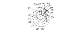
上記各実施形態において、図11(a)、(b)に示すように、ガイト外壁20の内側面から内側に突出させて、好ましくは傾斜する内側面を備える位置矯正リブ90を設けておくこともできる。詰替え容器用栓体10を被詰替え容器の口首部に位置決めして押し込む際に、位置矯正リブ90の例えば傾斜面を口首部の外周面に乗り上げさせることによって、流出筒17cに沿って突出させた栓蓋18の押込み凸部18cを、口首部16の先端側に誘導することが可能になる。これによって、栓蓋18の押込み凸部18cを口首部の先端に確実に当接させて、栓蓋18を装着筒17dから脱落させることで、流出開口をさらに容易に開放させることが可能になる。
In each of the above-described embodiments, as shown in FIGS. 11A and 11B, a
また、図12及び図13に示すように、位置矯正リブ90を挟んだ両側の部分に、切り込み91を設けることによって、位置矯正リブ90を、栓本体17の天面板17aから板バネ状に立設させた状態で設けることもできる。これによって、例えば被詰替え容器の口首部の外周面に雄ネジ凸条が形成されていて、位置矯正リブ90と干渉し易くなっている場合でも、位置矯正リブ90を外側に弾性変形させることで、干渉を回避することが可能になる。また位置矯正リブ90が外側に弾性変形することで、内側への弾性付勢力が生じるので、押込み凸部18cを、被詰替え容器の口首部の先端側に正確に誘導することが可能になる。これらによって、よりスムーズに詰め替え操作を行うことが可能になる。
Also, as shown in FIGS. 12 and 13, by providing
10,30,40 詰替え容器用栓体
11 詰替え容器
12 詰替え容器の口首部
12a 詰替え流出口
15 被詰替え容器
16 被詰替え容器の口首部
17 栓本体
17a 天面板
17b 流出開口
17c,17c’,17c” 流出筒
17d 装着筒
18,18” 栓蓋
18a,18a” 装着壁面部
18b,18b” 閉塞板部
18c,18c” 押込み凸部
18d 押込み凸部の先端面
19,19” 挿通口
20 ガイト外壁
20a 内周形状部分
21 ガイト内壁
21a 外周形状部分
21b 分断部
22 固定スカート部
23 分断部
24 括れ部
90 位置矯正リブ
91 切り込み
10, 30, 40 Refill container plug 11
Claims (12)
前記詰替え流出口の開口周縁部分に接合固定される栓本体と、該栓本体の天面板に開口形成された流出開口を流出方向内側から閉塞して、栓本体に着脱可能に装着される栓蓋とからなり、
前記栓本体は、前記流出開口を囲んで前記天面板から流出方向外側に突出する流出筒と、前記流出開口を囲んで前記天面板から流出方向内側に突出する装着筒とを備えており、
前記栓蓋は、外周面が前記装着筒の内周面に密着する装着壁面部と、前記装着筒の中空断面形状と同様の平面形状を有する閉塞板部と、該閉塞板部の周縁部分から立設する押込み凸部とを備えており、
前記押込み凸部を、前記流出開口の開口周縁部に連続して切欠き形成された挿通口、又は前記流出開口に隣接して形成された挿通口を介して、前記天面板から前記流出筒に沿って流出方向外側に突出させた状態で、前記栓蓋が前記栓本体に装着されている詰替え容器用栓体。 A refill container plug that covers the refill outlet of the refill container for refilling the contents of the refill container,
A plug body that is bonded and fixed to the peripheral edge portion of the opening of the refill outlet, and a plug that is detachably mounted on the plug body by closing the outflow opening formed in the top plate of the plug body from the inside in the outflow direction. A lid,
The plug body includes an outflow cylinder that protrudes outward in the outflow direction from the top plate surrounding the outflow opening, and a mounting cylinder that protrudes in the outflow direction from the top plate surrounding the outflow opening,
The plug lid includes a mounting wall surface portion whose outer peripheral surface is in close contact with the inner peripheral surface of the mounting tube, a closing plate portion having a planar shape similar to the hollow cross-sectional shape of the mounting tube, and a peripheral portion of the closing plate portion It has a push-in projection that stands upright,
From the top plate to the outflow tube, the push-in convex portion is inserted into the outflow opening through the insertion opening formed continuously in the peripheral edge of the outflow opening or through the insertion opening formed adjacent to the outflow opening. A stopper for a refill container in which the stopper lid is attached to the stopper body in a state where the stopper lid protrudes outward along the outlet direction.
Priority Applications (1)
| Application Number | Priority Date | Filing Date | Title |
|---|---|---|---|
| JP2013246319A JP6183846B2 (en) | 2012-11-30 | 2013-11-28 | Refill container stopper |
Applications Claiming Priority (3)
| Application Number | Priority Date | Filing Date | Title |
|---|---|---|---|
| JP2012262819 | 2012-11-30 | ||
| JP2012262819 | 2012-11-30 | ||
| JP2013246319A JP6183846B2 (en) | 2012-11-30 | 2013-11-28 | Refill container stopper |
Publications (3)
| Publication Number | Publication Date |
|---|---|
| JP2014129140A JP2014129140A (en) | 2014-07-10 |
| JP2014129140A5 JP2014129140A5 (en) | 2016-11-04 |
| JP6183846B2 true JP6183846B2 (en) | 2017-08-23 |
Family
ID=51407947
Family Applications (1)
| Application Number | Title | Priority Date | Filing Date |
|---|---|---|---|
| JP2013246319A Active JP6183846B2 (en) | 2012-11-30 | 2013-11-28 | Refill container stopper |
Country Status (1)
| Country | Link |
|---|---|
| JP (1) | JP6183846B2 (en) |
Families Citing this family (2)
| Publication number | Priority date | Publication date | Assignee | Title |
|---|---|---|---|---|
| US12091222B2 (en) | 2019-05-24 | 2024-09-17 | Conopco Inc. | Cap system for a concentrated refill capsule |
| US12060199B2 (en) | 2019-05-24 | 2024-08-13 | Conopco Inc. | Cap assembly for a concentrated refill capsule |
Family Cites Families (8)
| Publication number | Priority date | Publication date | Assignee | Title |
|---|---|---|---|---|
| JPH0618262U (en) * | 1992-08-13 | 1994-03-08 | コスモ石油株式会社 | Inner lid cap of chemical container |
| JP4352671B2 (en) * | 2002-09-06 | 2009-10-28 | 東洋製罐株式会社 | Hand free refill container |
| DE102008012973B3 (en) * | 2008-03-06 | 2009-04-02 | Henkel Ag & Co. Kgaa | System for refilling flowable or pourable detergents or cleaners |
| JP5661277B2 (en) * | 2009-12-25 | 2015-01-28 | 株式会社吉野工業所 | Refill container |
| JP5489755B2 (en) * | 2010-01-29 | 2014-05-14 | 株式会社吉野工業所 | Pouring cap |
| JP5523899B2 (en) * | 2010-03-31 | 2014-06-18 | 株式会社吉野工業所 | Refill nozzle |
| JP5819595B2 (en) * | 2010-07-30 | 2015-11-24 | 株式会社吉野工業所 | Refill container |
| JP5730011B2 (en) * | 2010-12-28 | 2015-06-03 | 花王株式会社 | Refill container stopper |
-
2013
- 2013-11-28 JP JP2013246319A patent/JP6183846B2/en active Active
Also Published As
| Publication number | Publication date |
|---|---|
| JP2014129140A (en) | 2014-07-10 |
Similar Documents
| Publication | Publication Date | Title |
|---|---|---|
| JP6183847B2 (en) | Refill container stopper | |
| WO2014084264A1 (en) | Refilling container stopper | |
| CN110035957B (en) | Pouring spout of refill container and connecting structure for connecting pouring spout of refill container to pouring unit of packaging container | |
| JP5428468B2 (en) | Cap for refill container and refill container | |
| JP5756357B2 (en) | Refillable soft packaging container | |
| JP5977642B2 (en) | Refill container stopper | |
| JP6183846B2 (en) | Refill container stopper | |
| TW201343490A (en) | Plug member for refill container | |
| JP5790114B2 (en) | Repeated use container | |
| JP5365283B2 (en) | Refill container | |
| JP6083855B2 (en) | Refill container stopper | |
| JP5977641B2 (en) | Refill container stopper | |
| JP2017074964A (en) | Transferring cap and transferring container into which cap is inserted | |
| JP5730011B2 (en) | Refill container stopper | |
| JP5978093B2 (en) | Refill container stopper | |
| JP5955585B2 (en) | Pouring cap | |
| JP5953041B2 (en) | Refill container stopper | |
| JP6405088B2 (en) | Refill bag container | |
| JP2015105110A (en) | Plug for refill container | |
| US9227766B2 (en) | Pouring spout for container | |
| JP2013177171A (en) | Pouring cap | |
| JP2015024864A (en) | Soft packaging container for refilling | |
| JP2010274998A (en) | Refill container | |
| JP2024104695A (en) | Refill container plug and refill container equipped with same | |
| JP2024104693A (en) | Refill container plug and refill container equipped with same |
Legal Events
| Date | Code | Title | Description |
|---|---|---|---|
| RD03 | Notification of appointment of power of attorney |
Free format text: JAPANESE INTERMEDIATE CODE: A7423 Effective date: 20160125 |
|
| A521 | Request for written amendment filed |
Free format text: JAPANESE INTERMEDIATE CODE: A523 Effective date: 20160914 |
|
| A621 | Written request for application examination |
Free format text: JAPANESE INTERMEDIATE CODE: A621 Effective date: 20160914 |
|
| A977 | Report on retrieval |
Free format text: JAPANESE INTERMEDIATE CODE: A971007 Effective date: 20170628 |
|
| TRDD | Decision of grant or rejection written | ||
| A01 | Written decision to grant a patent or to grant a registration (utility model) |
Free format text: JAPANESE INTERMEDIATE CODE: A01 Effective date: 20170704 |
|
| RD04 | Notification of resignation of power of attorney |
Free format text: JAPANESE INTERMEDIATE CODE: A7424 Effective date: 20170719 |
|
| A61 | First payment of annual fees (during grant procedure) |
Free format text: JAPANESE INTERMEDIATE CODE: A61 Effective date: 20170719 |
|
| R151 | Written notification of patent or utility model registration |
Ref document number: 6183846 Country of ref document: JP Free format text: JAPANESE INTERMEDIATE CODE: R151 |
|
| R250 | Receipt of annual fees |
Free format text: JAPANESE INTERMEDIATE CODE: R250 |
|
| R250 | Receipt of annual fees |
Free format text: JAPANESE INTERMEDIATE CODE: R250 |
|
| R250 | Receipt of annual fees |
Free format text: JAPANESE INTERMEDIATE CODE: R250 |
|
| R250 | Receipt of annual fees |
Free format text: JAPANESE INTERMEDIATE CODE: R250 |
|
| R250 | Receipt of annual fees |
Free format text: JAPANESE INTERMEDIATE CODE: R250 |