JP6183614B2 - Coin sorting device and coin sorting device equipped with the coin sorting device - Google Patents
Coin sorting device and coin sorting device equipped with the coin sorting device Download PDFInfo
- Publication number
- JP6183614B2 JP6183614B2 JP2014093196A JP2014093196A JP6183614B2 JP 6183614 B2 JP6183614 B2 JP 6183614B2 JP 2014093196 A JP2014093196 A JP 2014093196A JP 2014093196 A JP2014093196 A JP 2014093196A JP 6183614 B2 JP6183614 B2 JP 6183614B2
- Authority
- JP
- Japan
- Prior art keywords
- coin
- diameter
- small
- diameter coin
- passage
- Prior art date
- Legal status (The legal status is an assumption and is not a legal conclusion. Google has not performed a legal analysis and makes no representation as to the accuracy of the status listed.)
- Active
Links
Images


Description
本発明は、異なる金種の硬貨を機械的に金種毎に異なる硬貨通路へ振り分ける硬貨振分装置に関する。換言すれば、直径の異なる大径硬貨と小径硬貨をそれぞれ対応する大径硬貨通路又は小径硬貨通路に機械的に振り分ける硬貨振分装置に関する。
さらに、小径硬貨たる100円硬貨と大径硬貨たる10円硬貨とをそれぞれ小径硬貨通路たる100円硬貨通路又は大径硬貨通路たる10円硬貨通路に機械的に振り分ける硬貨振分装置に関する。
さらにまた、本発明は異なる金種の硬貨を機械的に金種毎に異なる硬貨通路へ振り分けた後、金種毎に保留し、所定の金額が保留された場合、保留した硬貨を開放できる硬貨振分装置を備えた硬貨選別装置に関する。
詳しくは、本発明は異なる金種の硬貨を機械的に金種毎に異なる硬貨通路へ振り分けた後、金種毎に保留し、所定の金額が保留された場合、自動的に開放するようにした機械式の硬貨振分装置を備えた硬貨選別装置に関する。
さらには、直径及び重量が近似する大径硬貨及び小径硬貨の両方とも正貨と偽貨とに選別した後、大径硬貨と小径硬貨とに分けて所定数保留し、保留硬貨が所定金額に達した場合、自動的に開放する機械式の硬貨振分装置を用いる硬貨選別装置に関する。
なお、本明細書で使用する「硬貨」は、通貨であるコインの他、ゲーム機のメダルやトークン等の代用貨幣または類似のものを包含し、形状は円盤型及び英国20ペンス及び50ペンスのような多角形であるが実質円形状の硬貨を含む。
The present invention relates to a coin sorting device that mechanically distributes coins of different denominations to different coin paths for each denomination. In other words, the present invention relates to a coin sorting apparatus that mechanically sorts large-diameter coins and small-diameter coins having different diameters into corresponding large-diameter coin passages or small-diameter coin passages.
Furthermore, the present invention relates to a coin sorting device that mechanically sorts a 100-yen coin as a small-diameter coin and a 10-yen coin as a large-diameter coin into a 100-yen coin path as a small-diameter coin path or a 10-yen coin path as a large-diameter coin path.
Furthermore, the present invention mechanically distributes coins of different denominations to different coin passages for each denomination and then holds them for each denomination. When a predetermined amount is held, a coin that can release the held coins The present invention relates to a coin sorting device including a sorting device.
Specifically, in the present invention, after coins of different denominations are mechanically distributed to different coin passages for each denomination, they are held for each denomination and automatically opened when a predetermined amount is held. The present invention relates to a coin sorting device equipped with a mechanical coin sorting device.
Furthermore, after sorting both large and small diameter coins with similar diameters and weights into regular coins and fake coins, a predetermined number of coins are reserved and divided into large coins and small coins. The present invention relates to a coin sorting device using a mechanical coin sorting device that automatically opens when it reaches.
As used herein, the term “coin” includes coins as a currency, as well as substitute coins such as medals and tokens of game machines or similar items, and the shape is a disk type and English 20 pence and 50 pence. Including such a polygonal but substantially circular coin.
複数の金種の硬貨を機械的に振分する第1の従来技術として本出願人が提案した、コインの厚みより僅かに大きい間隔で垂直に対向配置した平板状のベースボードとガイドボードとより画定され、コイン口に続いて上下方向に延びるコイン通路と、前記コイン口の下方において前記コイン通路に臨んで所定の選別すべき大径コインよりも僅かに小さい間隔で配置された第1係止体と第2係止体とを含み、選別する大径コインを保持した際、所定の横方向に回動する大径コイン用クレードル、 前記大径コイン用クレードルよりも下流の前記コイン通路に臨んで所定の選択すべき小径コインよりも僅かに小さい間隔で配置され第3係止体と第4係止体とを含み、選別する小径コインを保持した際、前記大径コイン用クレードルと同じ横方向に回動される小径コイン用クレードル、前記大径コイン用クレードルの前記横方向の下流側側方に、前下がりに配置された大径コインガイドレール、前記小径コイン用クレードルの前記横方向の下流側側方に、前下がりに配置された小径コインガイドレール、前記大径コインガイドレールの側方の前記ベースボードに開口した透孔、 前記透孔に続いて前記ベースボードの裏面側に形成した大径コイン通路、及び、前記大径コイン通路の下端部に形成された大径コイン口、前記小径コインガイドレールの下流に配置したアンビル、前記アンビルに並列に配置された振分体、前記振分体よりも前記アンビルに近い位置に形成した小径コイン偽貨口、前記振分体よりも前記アンビルに対し遠い位置に形成した小径コイン正貨口を含むことを特徴とするコイン選別装置が知られている(例えば、特許文献1参照)。
第2の従来技術として本出願人の出願に係る、少なくとも異なる金種の第1金種硬貨及び第2金種硬貨を保留し、所定金額になった場合、当該保留された硬貨を開放するようにした複数金種硬貨保留装置において、垂立する案内板の第1側に設けられた前記第1金種硬貨のための第1通路と、前記案内板の裏側である第2側に設けられた前記第2金種硬貨のための第2通路と、前記第1通路に配置され、前記第1金種硬貨を保留しない第1待機位置と前記第1金種硬貨を保留する第1保留位置及び保留した前記第1金種硬貨を解除する第1解除位置をとり得る小径硬貨保留装置、前記第2通路に配置され、前記第2金種硬貨を保留しない第2待機位置と前記第2金種硬貨を保留する第2保留位置及び保留した前記第2金種硬貨を解除する第2解除位置をとり得る大径硬貨保留装置、前記小径硬貨保留装置が前記第1保留位置に位置する場合、前記大径硬貨保留装置を前記第2保留位置をとることは可能であるが、前記第2解除位置への移動を不能とし、前記大径硬貨保留装置が前記第2保留位置に位置する場合、前記小径硬貨保留装置を前記第1保留位置をとることは可能であるが、前記第1解除位置への移動を不能とし、かつ、前記小径硬貨保留装置及び前記大径硬貨保留装置が共に前記第1保留位置、前記第2保留位置になった場合、前記第1解除位置又は前記第2解除位置へ移動可能とする第1連携装置、を有することを特徴とする複数金種硬貨保留装置が知られている(例えば、特許文献2参照)。
As a first conventional technique for mechanically allocating coins of multiple denominations, the present applicant has proposed a flat base board and a guide board that are vertically opposed to each other with an interval slightly larger than the coin thickness. A coin path that is defined and extends in the up-down direction following the coin slot, and a first latch disposed at a slightly smaller interval than the predetermined large-diameter coin that faces the coin path below the coin slot. A large-diameter coin cradle that rotates in a predetermined lateral direction when holding a large-diameter coin to be sorted, including a body and a second locking body, and faces the coin passage downstream of the large-diameter coin cradle When the small-diameter coin to be sorted is held, which is arranged at a slightly smaller interval than the predetermined small-diameter coin to be selected and holds the small-diameter coin to be sorted, the same side as the large-diameter coin cradle Rotated in the direction A cradle for diameter coins, a large-diameter coin guide rail arranged in a front-down direction on the downstream side in the lateral direction of the large-diameter coin cradle, and a laterally downstream side of the cradle for small-diameter coins, A small-diameter coin guide rail disposed at the front lower side, a through hole opened in the base board on the side of the large-diameter coin guide rail, a large-diameter coin passage formed on the back side of the base board following the through hole, And a large-diameter coin opening formed at a lower end of the large-diameter coin passage, an anvil disposed downstream of the small-diameter coin guide rail, a sorting body arranged in parallel to the anvil, and more than the sorting body Coin sorting characterized by including a small-diameter coin false coin mouth formed at a position close to an anvil and a small-diameter coin genuine coin mouth formed at a position farther from the anvil than the anvil Location is known (e.g., see Patent Document 1).
As a second conventional technique, at least a first denomination coin and a second denomination coin of different denominations according to the applicant's application are reserved, and when the predetermined amount is reached, the reserved coin is released. In the multiple denomination coin holding device, the first passage for the first denomination coin provided on the first side of the guide plate to be suspended and the second side which is the back side of the guide plate are provided. A second passage for the second denomination coin, a first standby position that is disposed in the first passage and does not hold the first denomination coin, and a first holding position that holds the first denomination coin. And a small-diameter coin holding device that can take a first release position for releasing the held first denomination coin, a second standby position that is arranged in the second passage and does not hold the second denomination coin and the second gold 2nd solution which cancels | releases the said 2nd denomination coin which hold | maintained the 2nd holding position which holds a seed coin When the large-diameter coin retaining device that can take a position and the small-diameter coin retaining device are located at the first retaining position, the large-diameter coin retaining device can take the second retaining position. When the movement to the release position is disabled and the large-diameter coin holding device is located at the second holding position, the small-diameter coin holding device can take the first holding position, but the first release When the movement to the position is disabled and the small diameter coin retaining device and the large diameter coin retaining device are both in the first retaining position and the second retaining position, the first releasing position or the second releasing position 2. Description of the Related Art A multi-denomination coin holding device having a first linkage device that can move to a position is known (see, for example, Patent Document 2).
この種の硬貨振分装置は、用いられる機器がゲーム機やコイン作動式自動機器であるため設置スペースが限られている。具体的には、縦横の寸法において3.5インチが世界的なデファクトスタンダードになっており、改良や機能を追加する場合であっても、互換性を確保するため、当該寸法の内に収めなければならない。
第1の従来技術において、大径コインは、大径コイン用クレードルによって横方向へ案内された後、大径コインガイドレール上を転動した後、ベースボードに形成された透孔を通って当該ベースボードの裏面側に案内された後、大径コイン口から落下する。小径コインは、大径コイン用クレードルに支持されることなく落下した後、下方に配置されている小径コイン用クレードルによって支持され、自身の重量によって生じるモーメントによって横方向へ案内されて小径コインガイドレール上に落下して当該小径コインガイドレール上を転動した後、アンビルに衝突させることで正貨と偽貨とに振り分けている。
この構成は、世界的な機械式硬貨選別装置のデファクトスタンダードである縦横3.5インチの範囲を振分装置としてフルに使用する場合においては実現可能であるが、フルに使用できない場合には設置することができない問題がある。換言すれば、追加機能構造によって硬貨振分装置の設置範囲が狭められた場合には設置できない問題がある。その原因は、大径コイン及び小径コイン共に横向きの投入通路から投入される場合、クレードルに達する前にコインの位置及び挙動を安定させるために短いながらも横向きの通路が必要であるため、当該横向き通路の長さ分、大型化してしまうためである。
第2の従来技術においては、大径硬貨と小径硬貨とを振分する機構は第1の従来技術と同一であり、さらに、最初に投入された大径硬貨又は小径硬貨を保留し、次ぎに投入された大径硬貨又は小径硬貨によって、所定の組合せになった場合、当該保留を解いて大径硬貨及び小径硬貨を受入れるようになっている。したがって、保留機能を担う構成を設置するため第1の従来技術同様に一層の小型化が必要である。換言すれば、保留装置を備えなければならないので複数金種振分装置を一層小型化せねばならない問題がある。
Since this type of coin sorting apparatus is a game machine or a coin-operated automatic device, the installation space is limited. Specifically, in the vertical and horizontal dimensions, 3.5 inches is the global de facto standard, and even when improvements and functions are added, it must be included within these dimensions to ensure compatibility. .
In the first prior art, the large-diameter coin is guided in the lateral direction by the large-diameter coin cradle, then rolls on the large-diameter coin guide rail, and then passes through the through hole formed in the base board. After being guided to the back side of the base board, it falls from the large coin slot. After the small coin is dropped without being supported by the large coin cradle, the small coin is supported by the small coin cradle arranged below, and is guided in the lateral direction by the moment generated by its own weight, and the small coin guide rail. After falling down and rolling on the small-diameter coin guide rail, it is sorted into a genuine coin and a fake coin by colliding with an anvil.
This configuration is feasible when the entire range of 3.5 inches in length and width, which is the de facto standard for global mechanical coin sorters, is used as a sorter, but should be installed when it cannot be used fully. There is a problem that can not be. In other words, there is a problem that it cannot be installed when the installation range of the coin sorting device is narrowed by the additional functional structure. The reason for this is that when both large-diameter coins and small-diameter coins are inserted from a lateral insertion passage, a short but lateral passage is required to stabilize the position and behavior of the coin before reaching the cradle. This is because the size of the passage increases.
In the second conventional technology, the mechanism for allocating the large-diameter coin and the small-diameter coin is the same as that in the first conventional technology. When a predetermined combination is made by the inserted large-diameter coin or small-diameter coin, the suspension is released and the large-diameter coin and the small-diameter coin are received. Therefore, further downsizing is required as in the first prior art in order to install a configuration that bears the hold function. In other words, since a holding device must be provided, there is a problem that the multiple denomination sorting device must be further downsized.
本発明の基本的目的たる第1の目的は、複数金種の硬貨を各金種別に振分することができる小型の機械式の複数金種振分装置を提供すること、換言すれば、大径硬貨と小径硬貨との二金種を正貨と偽貨に選別できると共に大径硬貨を大径硬貨通路に、小径硬貨を小径硬貨通路に振り分け出来る機械式の硬貨振分装置を提供することである。
本発明の従的目的たる第2の目的は、複数金種硬貨の硬貨を各金種別に振分することができる小型であって、かつ、安価な機械式の複数金種振分装置を提供することである。
本発明の従的目的たる第3の目的は、複数金種の硬貨を各金種別に振分することができると共に、返却する際に硬貨ジャムを生じない機械式の硬貨振分装置を提供することである。
本発明の従的目的たる第4の目的は、複数金種の硬貨を各金種別に振分することができると共に正貨を保留した後、開放できる小型の機械式、換言すれば、小型であって、電源が無くとも複数金種の硬貨を保留し、所定金額になった場合に開放して受け入れることができる、更に換言すれば、大径硬貨と小径硬貨との二金種を正貨と偽貨に選別できると共に大径硬貨を大径硬貨通路に、小径硬貨を小径硬貨通路に振り分けた後、正貨を保留し、かつ、大径硬貨と小径硬貨とがそれぞれ所定数になった場合に開放できる硬貨振分装置を有する硬貨選別装置を提供することである。
本発明の従的目的たる第5の目的は、複数金種の硬貨を各金種別に振分することができると共に正貨を保留した後、開放できる小型の機械式であって、かつ、安価な硬貨振分装置を有する硬貨選別装置を提供することである。
The first object, which is the basic object of the present invention, is to provide a small mechanical multiple denomination sorting device that can sort coins of multiple denominations into each denomination, in other words, To provide a mechanical coin sorting device that can sort two types of coins of a diameter coin and a small diameter coin into a genuine coin and a fake coin and distribute a large diameter coin to a large diameter coin passage and a small diameter coin to a small diameter coin passage. It is.
A second object as a subordinate object of the present invention is to provide a small and inexpensive mechanical multi-denomination sorter that can sort coins of multiple denominations into denominations. It is to be.
A third object as a subordinate object of the present invention is to provide a mechanical coin sorting device that can sort coins of a plurality of denominations to each denomination and that does not cause coin jam when returned. That is.
The fourth object of the present invention is a small mechanical type that can distribute coins of a plurality of denominations to each denomination and that can be opened after holding a genuine coin, in other words, small in size. Even if there is no power supply, it can hold coins of multiple denominations, and can open and accept them when the amount reaches a predetermined amount, in other words, two denominations of large and small coins After sorting the large-diameter coins into the large-diameter coin passage and the small-diameter coins into the small-diameter coin passage, the genuine coins were held, and the large-diameter coins and the small-diameter coins became the predetermined numbers respectively. To provide a coin sorting device having a coin sorting device that can be opened in some cases.
The fifth object, which is a subordinate object of the present invention, is a small mechanical type that can distribute coins of a plurality of denominations to each denomination and that can be opened after holding a genuine coin and is inexpensive. It is to provide a coin sorting device having a special coin sorting device.
この目的を達成するため、請求項1に係る第1の発明は以下のように構成されている。
同一の縦長の硬貨投入口から投入した小径硬貨及び大径硬貨を対応する小径硬貨通路又は大径硬貨通路に案内する硬貨振分装置において、
平板状のガイドボードの一側に配置され、前記硬貨投入口(108)に続いて形成された横向案内通路と、
前記横向案内通路に続いて形成された上下方向に延びる硬貨振分通路と、
前記ガイドボードに対し前記硬貨振分通路と同一側に設けられた前記小径硬貨通路と、
前記ガイドボードに対する前記小径硬貨通路の反対側に配置された前記大径硬貨通路と、
前記硬貨投入口の下方において前記硬貨振分通路に臨んで所定の間隔で配置された第1係止体と第2係止体とを含み、前記第1係止体と前記第2係止体は同心状態に配置されると共に、前記第2係止体は前記第1係止体の周囲を部分的に回動可能に配置され、前記第2係止体が待受位置に位置する場合、前記第1係止体と前記第2係止体との距離は前記小径硬貨の直径よりも僅かに小さく設定され、前記小径硬貨又は大径硬貨を保持した際、それら小径硬貨又は大径硬貨の重量によって前記硬貨投入口から遠ざかる方向に回動する前記第2係止体を備える硬貨選別クレードルと、
前記硬貨選別クレードルが所定量回動された場合、前記第2係止体との距離が前記小径硬貨の直径よりも大きいが、前記大径硬貨の直径よりも小さくなるよう設定された前記第1係止体と、
前記硬貨選別クレードルの回動を、前記第1係止体と第2係止体との距離が前記小径硬貨の直径よりも大きくなった前記第2係止体の回動位置であって、かつ、前記大径硬貨の重心が前記硬貨投入口側であり、さらに、前記大径硬貨が自重により落下可能な位置において停止させる硬貨選別ストッパと、
前記硬貨選別ストッパの近傍の前記ガイドボードに形成され、前記大径硬貨が通過可能であって、かつ、前記大径硬貨通路に連通する移動開口と、
前記硬貨選別クレードルが前記硬貨選別ストッパに係止されて前記大径硬貨が自重によって落下する際、前記硬貨選別ストッパよりも前記硬貨投入口側に配置され、前記自重によって落下する大径硬貨を前記移動開口を通って前記大径硬貨通路へ案内する移動ガイドと
を設けたことを特徴とする硬貨振分装置である。
In order to achieve this object, the first invention according to
In a coin sorting device that guides a small-diameter coin and a large-diameter coin inserted from the same vertically long coin slot into a corresponding small-diameter coin path or large-diameter coin path,
A lateral guide passage disposed on one side of a flat guide board and formed following the coin slot (108);
A coin distribution passage extending in the up-down direction and formed following the lateral guide passage;
The small-diameter coin passage provided on the same side as the coin distribution passage with respect to the guide board;
The large diameter coin passage disposed on the opposite side of the small diameter coin passage with respect to the guide board;
The first locking body and the second locking body include a first locking body and a second locking body disposed at a predetermined interval facing the coin distribution path below the coin insertion slot. Are arranged in a concentric state, and the second locking body is arranged so as to be partially rotatable around the first locking body, and the second locking body is located at the standby position, The distance between the first locking body and the second locking body is set slightly smaller than the diameter of the small diameter coin, and when the small diameter coin or the large diameter coin is held, the small diameter coin or the large diameter coin A coin sorting cradle comprising the second locking body that rotates in a direction away from the coin slot by weight;
When the coin sorting cradle is rotated by a predetermined amount, the distance from the second locking body is larger than the diameter of the small-diameter coin, but is set to be smaller than the diameter of the large-diameter coin. A locking body;
The rotation of the coin sorting cradle is the rotation position of the second locking body in which the distance between the first locking body and the second locking body is larger than the diameter of the small-diameter coin; and The center of gravity of the large-diameter coin is on the coin slot side, and further, a coin sorting stopper for stopping the large-diameter coin at a position where it can fall by its own weight,
A moving opening formed on the guide board in the vicinity of the coin sorting stopper, through which the large-diameter coin can pass, and communicated with the large-diameter coin path;
When the coin sorting cradle is locked to the coin sorting stopper and the large-diameter coin falls by its own weight, the large-diameter coin placed by the coin insertion port side of the coin sorting stopper is dropped by the own weight. It is a coin distribution device provided with the movement guide which guides to the above-mentioned large diameter coin passage through a movement opening.
請求項2に係る第2の発明は、同一の縦長の硬貨投入口から投入した小径硬貨及び大径硬貨を対応する小径硬貨通路又は大径硬貨通路に案内する硬貨振分装置において、
前記小径硬貨、及び、前記大径硬貨の厚みより僅かに大きい間隔で垂直に対向配置した平板状のベースボードとガイドボードとの間において、前記硬貨投入口に続いて形成された横向案内通路と、
前記横向案内通路に続いて形成された上下方向に延びる硬貨振分通路と、
前記硬貨振分通路に連通し、前記ガイドボードに対し前記硬貨振分通路と同じ側に設けられた小径硬貨のための小径硬貨通路と、
前記ガイドボードに対し前記小径硬貨通路の反対側に設けられ、前記ガイドボードに取り付けられた第2ガイドボードとの間に形成された大径硬貨のための大径硬貨通路と、
前記硬貨投入口の下方において前記硬貨振分通路に臨んで所定の間隔で配置された第1係止体と第2係止体とを含み、前記第1係止体と前記第2係止体は同心状態に配置されると共に、前記第2係止体は前記第1係止体の周囲を部分的に回動可能に配置され、前記第2係止体が待受位置に位置する場合、前記第1係止体と前記第2係止体との距離は前記小径硬貨の直径よりも僅かに小さく設定され、前記小径硬貨又は大径硬貨を保持した際、それら小径硬貨又は大径硬貨の重量によって前記硬貨投入口から遠ざかる方向に回動する前記第2係止体を備える硬貨選別クレードルと、
前記硬貨選別クレードルが所定量回動された場合、前記第2係止体との距離が前記小径硬貨の直径よりも大きいが、前記大径硬貨の直径よりも小さくなるよう設定された前記第1係止体と、
前記硬貨選別クレードルの回動を、前記第1係止体と第2係止体との距離が前記小径硬貨の直径よりも大きくなった前記第2係止体の回動位置であって、かつ、前記大径硬貨の重心が前記硬貨投入口側であり、さらに、前記大径硬貨が自重により落下可能な位置において停止させる硬貨選別ストッパと、
前記硬貨選別ストッパの近傍の前記ガイドボードに形成され、前記大径硬貨が通過可能なであって、かつ、前記大径硬貨通路に連通する移動開口と、
前記硬貨選別クレードルが前記硬貨選別ストッパに係止されて前記大径硬貨が自重によって落下する際、前記硬貨選別ストッパよりも前記硬貨投入口側に配置され、前記自重によって落下する大径硬貨を前記移動開口を通って前記大径硬貨通路へ案内する移動ガイドと
を設けたことを特徴とする硬貨振分装置である。
According to a second aspect of the present invention, there is provided a coin sorting apparatus that guides a small-diameter coin and a large-diameter coin that are inserted from the same vertically long coin slot into a corresponding small-diameter coin path or a large-diameter coin path.
A lateral guide passage formed subsequent to the coin insertion slot between the small-diameter coin and a flat base board and a guide board that are vertically opposed to each other with an interval slightly larger than the thickness of the large-diameter coin; ,
A coin distribution passage extending in the up-down direction and formed following the lateral guide passage;
A small-diameter coin passage for a small-diameter coin that communicates with the coin-distributing passage and is provided on the same side as the coin-distributing passage with respect to the guide board;
A large-diameter coin passage for a large-diameter coin provided between the guide board and the second guide board provided on the opposite side of the small-diameter coin passage;
The first locking body and the second locking body include a first locking body and a second locking body disposed at a predetermined interval facing the coin distribution path below the coin insertion slot. Are arranged in a concentric state, and the second locking body is arranged so as to be partially rotatable around the first locking body, and the second locking body is located at the standby position, The distance between the first locking body and the second locking body is set slightly smaller than the diameter of the small diameter coin, and when the small diameter coin or the large diameter coin is held, the small diameter coin or the large diameter coin A coin sorting cradle comprising the second locking body that rotates in a direction away from the coin slot by weight;
When the coin sorting cradle is rotated by a predetermined amount, the distance from the second locking body is larger than the diameter of the small-diameter coin, but is set to be smaller than the diameter of the large-diameter coin. A locking body;
The rotation of the coin sorting cradle is the rotation position of the second locking body in which the distance between the first locking body and the second locking body is larger than the diameter of the small-diameter coin; and The center of gravity of the large-diameter coin is on the coin slot side, and further, a coin sorting stopper for stopping the large-diameter coin at a position where it can fall by its own weight,
A moving opening formed on the guide board in the vicinity of the coin sorting stopper, through which the large-diameter coin can pass, and communicated with the large-diameter coin passage;
When the coin sorting cradle is locked to the coin sorting stopper and the large-diameter coin falls by its own weight, the large-diameter coin placed by the coin insertion port side of the coin sorting stopper is dropped by the own weight. It is a coin distribution device provided with the movement guide which guides to the above-mentioned large diameter coin passage through a movement opening.
請求項3に係る第3の発明は、前記ガイドボードは前記ベースボードに対し上端部において回動自在であって、かつ、前記ベースボード側に近づくように付勢されると共に、前記小径硬貨通路を画定するための前記小径硬貨(SC)用のガイドレールが配置され、
前記ガイドボードに対し前記ベースボードの反対側に、前記ガイドボードに対し回動可能に支持されると共に前記大径硬貨(LC)用の第2ガイドボードが配置され、
返却レバの操作に連動して最初に前記ガイドボードを回動させて当該ガイドボードの下端を前記ベースボードから離隔して前記小径硬貨通路の下端部を開放させた後、前記第2ガイドボードを前記ガイドボードに対し回動させて当該第2ガイドボードの下端を前記ベースボードから離隔して前記大径硬貨通路を開放させる硬貨返却手段を設けたことを特徴とする請求項2に記載の硬貨振分装置である。
According to a third aspect of the present invention, the guide board is rotatable at an upper end with respect to the base board and is urged to approach the base board side, and the small-diameter coin path. A guide rail for the small-diameter coin (SC) for defining
A second guide board for the large-diameter coin (LC) is disposed on the opposite side of the base board with respect to the guide board and is rotatably supported with respect to the guide board.
First, the guide board is rotated in conjunction with the operation of the return lever, the lower end of the guide board is separated from the base board, and the lower end of the small-diameter coin passage is opened. 3. The coin according to claim 2, further comprising a coin return means that is pivoted with respect to the guide board to separate the lower end of the second guide board from the base board to open the large-diameter coin passage. It is a sorting device.
請求項4に係る第4の発明は、同一の硬貨投入口から投入した小径硬貨及び大径硬貨を対応する小径硬貨通路又は大径硬貨通路に案内する硬貨振分装置において、
平板状のガイドボードの一側に配置され、縦長の硬貨投入口に続いて形成された横向案内通路と、
前記横向案内通路に続いて形成された上下方向に延びる硬貨振分通路と、
前記ガイドボードに対し前記硬貨振分通路と同一側に設けられた前記小径硬貨通路と、
前記ガイドボードに対する前記小径硬貨通路の反対側に配置された前記大径硬貨通路と、
前記硬貨投入口の下方において前記硬貨振分通路に臨んで所定の間隔で配置された第1係止体と第2係止体とを含み、前記第1係止体と前記第2係止体は同心状態に配置されると共に、前記第2係止体は前記第1係止体の周囲を部分的に回動可能に配置され、前記第2係止体が待受位置に位置する場合、前記第1係止体と前記第2係止体との距離は前記小径硬貨の直径よりも僅かに小さく設定され、前記小径硬貨又は大径硬貨を保持した際、それら小径硬貨又は大径硬貨の重量によって前記硬貨投入口から遠ざかる方向に回動する前記第2係止体を備える硬貨選別クレードルと、
前記硬貨選別クレードルが所定量回動された場合、前記第2係止体との距離が前記小径硬貨の直径よりも大きいが、前記大径硬貨の直径よりも小さくなるよう設定された前記第1係止体と、
前記硬貨選別クレードルの回動を、前記第1係止体と前記第2係止体との距離が前記小径硬貨の直径よりも大きくなった前記第2係止体の回動位置であって、かつ、前記大径硬貨の重心が前記硬貨投入口側であり、さらに、前記大径硬貨が自重により落下可能な位置において停止させる硬貨選別ストッパと、
前記硬貨選別ストッパの近傍の前記ガイドボードに形成され、前記大径硬貨が通過可能であって、かつ、前記大径硬貨通路に連通する移動開口と、
前記硬貨選別クレードルが前記硬貨選別ストッパに係止されて前記大径硬貨が自重によって落下する際、前記硬貨選別ストッパよりも前記硬貨投入口側に配置され、前記自重によって落下する大径硬貨を前記移動開口を通って前記大径硬貨通路へ案内する移動ガイドと、
前記小径硬貨通路に配置され、前記小径硬貨を保留しない第1待機位置と前記小径硬貨を保留する第1保留位置及び保留した前記小径硬貨を解除する第1解除位置をとり得る小径硬貨保留装置と、
前記大径硬貨通路に配置され、前記大径硬貨を保留しない第2待機位置と前記大径硬貨を保留する第2保留位置及び保留した前記大径硬貨を解除する第2解除位置をとり得る大径硬貨保留装置と、
前記小径硬貨保留装置が前記第1保留位置に位置する場合、前記大径硬貨保留装置を前記第2保留位置をとることは可能であるが、前記第2解除位置への移動を不能とし、前記大径硬貨保留装置が前記第2保留位置に位置する場合、前記小径硬貨保留装置を前記第1保留位置をとることは可能であるが、前記第1解除位置への移動を不能とし、かつ、前記小径硬貨保留装置及び前記大径硬貨保留装置が共に前記第1保留位置、前記第2保留位置になった場合、前記第1解除位置又は前記第2解除位置へ移動可能とする連携装置と、
を有することを特徴とする硬貨振分装置を備えた硬貨選別装置である。
According to a fourth aspect of the present invention, there is provided a coin sorting apparatus that guides a small-diameter coin and a large-diameter coin that are inserted from the same coin slot into a corresponding small-diameter coin path or a large-diameter coin path.
A lateral guide passage formed on one side of a flat guide board and formed following a vertically long coin slot;
A coin distribution passage extending in the up-down direction and formed following the lateral guide passage;
The small-diameter coin passage provided on the same side as the coin distribution passage with respect to the guide board;
The large diameter coin passage disposed on the opposite side of the small diameter coin passage with respect to the guide board;
The first locking body and the second locking body include a first locking body and a second locking body disposed at a predetermined interval facing the coin distribution path below the coin insertion slot. Are arranged in a concentric state, and the second locking body is arranged so as to be partially rotatable around the first locking body, and the second locking body is located at the standby position, The distance between the first locking body and the second locking body is set slightly smaller than the diameter of the small diameter coin, and when the small diameter coin or the large diameter coin is held, the small diameter coin or the large diameter coin A coin sorting cradle comprising the second locking body that rotates in a direction away from the coin slot by weight;
When the coin sorting cradle is rotated by a predetermined amount, the distance from the second locking body is larger than the diameter of the small-diameter coin, but is set to be smaller than the diameter of the large-diameter coin. A locking body;
The rotation of the coin sorting cradle, a rotational position of the said distance between the first locking body and the second locking body is larger than the diameter of the small-diameter coin second engaging member, And the center of gravity of the large-diameter coin is the coin insertion slot side, and further, a coin sorting stopper for stopping at a position where the large-diameter coin can fall by its own weight,
A moving opening formed on the guide board in the vicinity of the coin sorting stopper, through which the large-diameter coin can pass, and communicated with the large-diameter coin path;
When the coin sorting cradle is locked to the coin sorting stopper and the large-diameter coin falls due to its own weight, the large-diameter coin placed by the coin insertion port side of the coin sorting stopper is dropped by the dead weight. A movement guide for guiding the large-diameter coin passage through the movement opening;
A small-diameter coin holding device arranged in the small-diameter coin passage and capable of taking a first standby position where the small-diameter coin is not held, a first holding position where the small-diameter coin is held, and a first release position where the held small-diameter coin is released ; ,
It is arranged in the large-diameter coin passage and can take a second standby position where the large-diameter coin is not retained, a second retention position where the large-diameter coin is retained, and a second release position where the retained large-diameter coin is released. and the diameter of the coin holding apparatus,
When the small-diameter coin retaining device is located at the first retaining position, the large-diameter coin retaining device can take the second retaining position, but cannot move to the second release position, When the large-diameter coin retaining device is located at the second retaining position, the small-diameter coin retaining device can take the first retaining position, but cannot be moved to the first release position; and the small diameter coin holding device and the large-diameter coin holding device are both the first holding position, when it becomes the second holding position, the linkage device for movable said to first release position and the second release position,
It is a coin sorter provided with the coin sorter characterized by having.
請求項5に係る第5の発明は、前記小径硬貨保留装置は、前記ガイドボードに対し横向きに配置された保留第1軸と、前記保留第1軸の軸心に対し同一円上に形成された第1待機規制部と第1保留規制部、及び、第1連携阻止部が形成された小径規制体と、前記小径規制体に一体に形成されると共に一端部が前記小径硬貨通路側に配置されて前記小径硬貨を保持する小径係止部とを含み、
前記大径硬貨保留装置は、前記保留第1軸の軸心に対し同一円上に形成された第2待機規制部と第2保留規制部、及び、第2連携阻止部を含む大径規制体と、一端部が保留第3軸に回動自在に取付られると共に他端部が前記大径硬貨通路に位置して前記大径硬貨を保持する大径係止部を有する大径係止体と、前記大径規制体と前記大径係止体とをリンク結合するリンク装置とを含み、
前記連携装置は、中間を保留第2軸に回動自在に支持された揺動体の一端部に設けられた保留第1ストッパ及び他端部に設けられた保留第2ストッパを含み、前記保留第1ストッパが前記第1待機規制部と前記第2待機規制部を係止する際は前記保留第2ストッパは前記第1連携阻止部と前記第2連携阻止部に相対し、及び、前記保留第1ストッパが前記第1保留規制部と前記第2保留規制部を係止する際は前記保留第2ストッパは前記第1連携阻止部と前記第2連携阻止部と非相対位置になる
ことを特徴とする請求項4に記載した硬貨振分装置を備えた硬貨選別装置である。
According to a fifth aspect of the present invention, the small-diameter coin retaining device is formed on the same circle with respect to the retaining first axis disposed laterally with respect to the guide board and the axis of the retaining first axis. The first standby regulating unit, the first holding regulating unit, and the small-diameter regulating body in which the first cooperation preventing unit is formed, and the one- end part is disposed on the small-diameter coin passage side while being integrally formed with the small-diameter regulating body. A small-diameter engaging portion that holds the small-diameter coin,
The large-diameter coin retaining device includes a second waiting restricting portion , a second retaining restricting portion, and a second cooperation preventing portion formed on the same circle with respect to the axis of the retaining first shaft. And a large-diameter locking body having a large-diameter locking portion that has one end portion rotatably attached to the retaining third shaft and the other end portion positioned in the large-diameter coin passage to hold the large-diameter coin. A link device for linking the large diameter restricting body and the large diameter locking body,
The linkage device includes a holding first stopper provided at one end of a rocking body rotatably supported by a holding second shaft in the middle, and a holding second stopper provided at the other end. When the first stopper locks the first standby restriction part and the second standby restriction part, the holding second stopper is opposed to the first cooperation prevention part and the second cooperation prevention part, and When the first stopper locks the first holding restricting portion and the second holding restricting portion, the holding second stopper is in a non-relative position with the first cooperation preventing portion and the second cooperation preventing portion. It is a coin sorting device provided with the coin sorter described in claim 4.
第1の発明によれば、同一の縦向きの硬貨投入口に投入された小径硬貨又は大径硬貨は、ガイドボードの一側に配置された横向案内通路を転動することにより、姿勢及び移動速度を所定範囲に制限された後、上下方向に延びる硬貨振分通路を落下する。硬貨振分通路に臨んでいる第1係止体及び第2係止体が待受状態である場合、第1係止体と第2係止体とが小径硬貨の直径よりも僅かに小さい間隔で配置されている。したがって、大径硬貨又は小径硬貨は、第1係止体と第2係止体とによって支えられる。これにより、硬貨選別クレードルに作用するモーメントが逆転し、第2係止体は第1係止体回りを所定方向である硬貨投入口から離れる方向へ回動される。そして、硬貨選別クレードルが所定量回動され、第1係止体に対する第2係止体の位置関係が所定の関係になった場合、第1係止体と第2係止体との間隔が小径硬貨の直径よりも大きくなるが、大径硬貨の直径よりは小さい。そして、硬貨選別クレードルは、所定角度回動されると、硬貨選別ストッパに係止されて当該回動を停止させられる。したがって、小径硬貨は第1係止体及び第2係止体の両方によって移動の制約を受けないので、硬貨選別クレードルが硬貨選別ストッパに係止された位置における小径硬貨の回動経路に対して法線方向へ、硬貨選別クレードルの回動と一体的に回動した際の慣性力によって、慣性移動して振り分けられる。
一方、硬貨選別クレードルが硬貨選別ストッパに係止された場合であっても、第1係止体と第2係止体との間隔は、大径硬貨の直径よりも小さいことから、大径硬貨は小径硬貨と同様の慣性力による法線方向の移動が阻止される。しかし、第2係止体が硬貨選別ストッパに係止された位置において、当該大径硬貨の重心は、前記第2係止体よりも硬貨投入口側に位置することから、大径硬貨には自身の重量によって、前記第2係止体との接点を支点にして回動するモーメントが作用する。このモーメントによって、大径硬貨は第2係止体との接点を支点に回動するようにして落下することから、硬貨投入口側へ近づきつつ落下する。
この移動過程において、大径硬貨の硬貨投入口側の端部は、移動ガイドによって大径通路側へ案内されることから、結果として、ガイドボードに形成された移動開口を通って大径硬貨通路へ案内される。
したがって、硬貨投入口に続いて横向案内通路が形成されている場合であっても、大径硬貨は硬貨選別クレードルが硬貨選別ストッパに係止された際に、第2係止部との接点を支点として硬貨投入口側へ戻される移動を利用して移動ガイドによって大径硬貨通路へ案内することから、硬貨投入口から離れる方向の寸法を大きくせずとも小径硬貨と大径硬貨とに振り分けることが出来るので、本発明の基本的目的である第1の目的を達成できる利点がある。
According to the first invention, the small-diameter coin or the large-diameter coin thrown into the same vertically oriented coin insertion slot rolls the lateral guide passage disposed on one side of the guide board, thereby moving the posture and movement. After the speed is limited to a predetermined range, the coin distribution passage extending in the vertical direction is dropped. When the first locking body and the second locking body facing the coin distribution path are in the standby state, the distance between the first locking body and the second locking body is slightly smaller than the diameter of the small coin. Is arranged in. Therefore, the large diameter coin or the small diameter coin is supported by the first locking body and the second locking body. As a result, the moment acting on the coin sorting cradle is reversed, and the second locking body is rotated around the first locking body in a direction away from the coin slot which is a predetermined direction. When the coin sorting cradle is rotated by a predetermined amount and the positional relationship of the second locking body with respect to the first locking body becomes a predetermined relationship, the distance between the first locking body and the second locking body is It is larger than the diameter of the small coin, but smaller than the diameter of the large coin. Then, when the coin sorting cradle is rotated by a predetermined angle, the coin sorting cradle is locked by the coin sorting stopper and stopped. Therefore, since the small-diameter coin is not restricted by the movement of both the first locking body and the second locking body, the small-diameter coin is moved relative to the rotation path of the small-diameter coin at the position where the coin sorting cradle is locked by the coin sorting stopper. In the normal direction, the inertial force when the coin sorting cradle is rotated together with the coin sorting cradle is moved by inertia and distributed.
On the other hand, even when the coin sorting cradle is locked to the coin sorting stopper, the distance between the first locking body and the second locking body is smaller than the diameter of the large diameter coin. Is prevented from moving in the normal direction due to the inertial force similar to small-diameter coins. However, since the center of gravity of the large-diameter coin is located closer to the coin slot than the second locking body at the position where the second locking body is locked to the coin sorting stopper, Due to its own weight, a moment that rotates around a contact point with the second locking body acts. Due to this moment, the large-diameter coin falls so as to rotate with the contact point with the second locking body as a fulcrum, and thus falls while approaching the coin slot.
In this moving process, the end of the large-diameter coin on the coin slot side is guided to the large-diameter passage side by the moving guide, and as a result, the large-diameter coin passage passes through the moving opening formed in the guide board. To be guided to.
Therefore, even when a lateral guide passage is formed following the coin slot, the large-diameter coin has a contact with the second locking portion when the coin sorting cradle is locked to the coin sorting stopper. Since it is guided to the large-diameter coin passage by the movement guide using the movement returned to the coin insertion port side as a fulcrum, it is distributed between the small-diameter coin and the large-diameter coin without increasing the dimension in the direction away from the coin insertion port. Therefore, there is an advantage that the first object which is the basic object of the present invention can be achieved.
第2の発明によれば、同一の縦向きの硬貨投入口に投入された小径硬貨又は大径硬貨は、ベースボードとガイドボードとの間に形成された小径硬貨及び大径硬貨の厚みよりも僅かに大きい間隔で形成された横向きの案内通路を転動することにより、姿勢及び移動速度を所定範囲に制限された後、上下方向に延びる硬貨振分通路を落下する。硬貨振分通路に臨んでいる第1係止体及び第2係止体が待受状態である場合、第1係止体と第2係止体とが小径硬貨の直径よりも僅かに小さい間隔で配置されている。したがって、大径硬貨又は小径硬貨の何れもの落下途上において、第1係止体と第2係止体とによって支えられる。これにより、硬貨選別クレードルに作用するモーメントが逆転し、第2係止体は第1係止体回りを所定方向、換言すれば硬貨投入口から離れる方向へ回動される。そして、硬貨選別クレードルが所定量回動され、第1係止体に対する第2係止体の位置関係が所定の関係になった場合、第1係止体と第2係止体との間隔が小径硬貨の直径よりも大きくなるが、大径硬貨の直径よりは小さい。そして、硬貨選別クレードルが所定角度回動された場合、硬貨選別ストッパに係止されて当該回動を停止させられる。したがって、小径硬貨は第1係止体及び第2係止体の両方によって移動の制約を受けないので、硬貨選別クレードルが硬貨選別ストッパに係止された位置における小径硬貨の回動経路に対して法線方向へ、硬貨選別クレードルの回動と一体的に回動した際の慣性力によって慣性移動し、ガイドボードに対して硬貨振分通路と同じ側に配置された小径硬貨通路に振り分けられる。
一方、第1係止体と第2係止体との間隔は、硬貨選別クレードルが硬貨選別ストッパに係止された場合であっても、大径硬貨の直径よりも小さいことから、大径硬貨は小径硬貨と同様な慣性力による移動は阻止される。しかし、第2係止体が硬貨選別ストッパに係止された位置において、当該大径硬貨の重心は、第2係止体との接点よりも硬貨投入口側に位置することから、大径硬貨には、自身の重量によって、第2係止体との接点を支点として硬貨投入口側へ回動しつつ落下するモーメントが作用する。このモーメントによって、大径硬貨は第2係止体との接点を支点に回動するようにして落下することから、硬貨投入口側へ近づきつつ落下する。
大径硬貨のこの移動過程において、その硬貨投入口側の端部は、移動ガイドによってガイドボードと第2ガイドボードとの間に形成された大径通路側へ案内されることから、結果として、ガイドボードに形成された移動開口を通ってガイドボードに対し小径硬貨通路の反対側に形成された大径硬貨通路へ案内される。
したがって、硬貨投入口に続いて横向案内通路が形成されている場合であっても、大径硬貨は硬貨選別クレードルが硬貨選別ストッパに係止された際に、第2係止部との接点を支点として硬貨投入口側へ戻される移動を利用して移動ガイドによって大径硬貨通路へ案内されることから、硬貨投入口から離れる方向の寸法を大きくせずとも小径硬貨と大径硬貨とに振り分け出来、本発明の基本的目的たる第1の目的を達成できる利点がある。
さらに、本第2の発明においては、ベースボードとガイドボードとにより構成できるので、安価に構成でき、本発明の従的目的である第2の目的を達成できる利点がある。
According to the second invention, the small-diameter coin or the large-diameter coin inserted into the same vertical coin slot is smaller than the thickness of the small-diameter coin and the large-diameter coin formed between the base board and the guide board. By rolling the lateral guide passage formed at slightly larger intervals, the posture and moving speed are limited to a predetermined range, and then the coin distribution passage extending in the vertical direction is dropped. When the first locking body and the second locking body facing the coin distribution path are in the standby state, the distance between the first locking body and the second locking body is slightly smaller than the diameter of the small coin. Is arranged in. Therefore, it is supported by the first locking body and the second locking body during the fall of either the large diameter coin or the small diameter coin. As a result, the moment acting on the coin sorting cradle is reversed, and the second locking body is rotated around the first locking body in a predetermined direction, in other words, away from the coin slot. When the coin sorting cradle is rotated by a predetermined amount and the positional relationship of the second locking body with respect to the first locking body becomes a predetermined relationship, the distance between the first locking body and the second locking body is It is larger than the diameter of the small coin, but smaller than the diameter of the large coin. When the coin sorting cradle is rotated by a predetermined angle, the coin sorting cradle is stopped by the coin sorting stopper. Therefore, since the small-diameter coin is not restricted by the movement of both the first locking body and the second locking body, the small-diameter coin is moved relative to the rotation path of the small-diameter coin at the position where the coin sorting cradle is locked by the coin sorting stopper. In the normal direction, the inertial force is moved by the inertial force when the coin sorting cradle is rotated integrally with the coin sorting cradle, and is distributed to the small-diameter coin path arranged on the same side as the coin distribution path with respect to the guide board.
On the other hand, since the interval between the first locking body and the second locking body is smaller than the diameter of the large-diameter coin, even when the coin sorting cradle is locked to the coin sorting stopper, the large-diameter coin Is prevented from moving by inertial force similar to small-diameter coins. However, since the center of gravity of the large-diameter coin is located closer to the coin slot than the contact with the second locking body at the position where the second locking body is locked to the coin sorting stopper, the large-diameter coin In this case, due to its own weight, a moment that falls while rotating to the coin slot side with the contact point with the second locking body as a fulcrum acts. Due to this moment, the large-diameter coin falls so as to rotate with the contact point with the second locking body as a fulcrum, and thus falls while approaching the coin slot.
In this movement process of the large-diameter coin, the end on the coin slot side is guided to the large-diameter passage formed between the guide board and the second guide board by the movement guide, It is guided to a large-diameter coin passage formed on the opposite side of the small-diameter coin passage through the moving opening formed in the guide board.
Therefore, even when a lateral guide passage is formed following the coin slot, the large-diameter coin has a contact with the second locking portion when the coin sorting cradle is locked to the coin sorting stopper. Since it is guided to the large-diameter coin passage by the movement guide using the movement returned to the coin insertion slot as a fulcrum, it is divided into small-diameter coins and large-diameter coins without increasing the dimension away from the coin insertion slot. This is advantageous in that the first object which is the basic object of the present invention can be achieved.
Furthermore, in the second invention, since it can be constituted by a base board and a guide board, it can be constructed at low cost, and there is an advantage that the second object which is a secondary object of the present invention can be achieved.
第3の発明において、ベースボードと共同して小径硬貨通路構成するガイドボードは、その上端部においてベースボードに対して回動自在であり、下端部には小径硬貨用のガイドレールが配置されている。これにより、ガイドボードを回動させた場合、小径硬貨通路の下面に小径硬貨用のガイドレールが位置せず、さらに小径硬貨用のガイドレール上面がその長手に対して横方向下向きに傾斜することから、当該ガイドレール上に載っている小径硬貨は小径硬貨通路から落下することができる。
また、ベースボードに対するガイドボードの反対側にはガイドボードに対し回動可能であって、下端部に大径硬貨用のガイドレールが配置された第2ガイドボードが取りつけられている。これにより、第2ガイドボードを回動させた場合、大径硬貨通路の下面に大径硬貨用のガイドレールが位置せず、さらに、大径硬貨用ガイドレールの上面がその長手に対して横方向下向きに傾斜することから、当該大径硬貨用ガイドレールの上面に載っている大径硬貨は大径硬貨通路から落下することができる。
さらに、返却レバが返却操作された場合、硬貨返却手段は、最初にガイドボードをベースボードに対して回動、すなわち、第2ガイドボードも一体的に回動させた後、第2ガイドボードをガイドボードに対して回動させる。換言すれば、返却レバの操作によって、最初に小径硬貨が落下されて返却された後、次ぎに大径硬貨が落下されて返却される。これによって、大径硬貨と小径硬貨とが同時に返却通路に落下することが無いのでコインジャムを生ぜず、大径硬貨と小径硬貨の返却を確実に行うことができ、本発明の第3の目的を達成することが出来る。
In the third invention, the guide board constituting the small diameter coin passage in cooperation with the base board is rotatable at the upper end portion with respect to the base board, and the guide rail for the small diameter coin is arranged at the lower end portion. Yes. Thereby, when the guide board is rotated, the guide rail for the small-diameter coin is not positioned on the lower surface of the small-diameter coin passage, and the upper surface of the guide rail for the small-diameter coin is inclined laterally downward with respect to the longitudinal direction. Therefore, the small-diameter coin placed on the guide rail can fall from the small-diameter coin passage.
In addition, a second guide board is mounted on the opposite side of the guide board with respect to the base board. As a result, when the second guide board is rotated, the guide rail for the large-diameter coin is not positioned on the lower surface of the large-diameter coin passage, and the upper surface of the large-diameter coin guide rail is transverse to the longitudinal direction. Since it inclines downward in the direction, the large-diameter coin placed on the upper surface of the guide rail for large-diameter coins can fall from the large-diameter coin passage.
Further, when the return lever is returned, the coin return means first rotates the guide board with respect to the base board, that is, the second guide board is also rotated integrally, and then the second guide board is rotated. Rotate with respect to the guide board. In other words, after the small-diameter coin is first dropped and returned by the operation of the return lever, the large-diameter coin is then dropped and returned. As a result, the large-diameter coin and the small-diameter coin do not fall into the return passage at the same time, so that no coin jam occurs, and the large-diameter coin and the small-diameter coin can be reliably returned, and the third object of the present invention. Can be achieved.
第4の発明において、大径硬貨と小径硬貨との硬貨振分装置の構成は、第1の発明と同一であるので第1の発明を同一の利点がある。、
さらに、第4の発明においては、小径硬貨通路に案内された小径硬貨は、第1待機位置に位置する小径硬貨保留装置によって小径硬貨通路に、大径硬貨は第2待機位置に位置する大径硬貨保留装置によって大径硬貨通路に保留される。小径硬貨保留装置と大径硬貨保留装置が小径硬貨、大径硬貨を保留する場合、それぞれ待機位置から保留位置へ移動される。
小径硬貨保留装置と大径硬貨保留装置とは、第1連携装置によって、小径硬貨保留装置と大径硬貨保留装置の両方が保留位置へ移動した場合、それらは大径硬貨又は小径硬貨を解除するための解除位置へそれぞれ移動可能になる。何れか一方が保留位置へ移動し、他方が待機位置に位置する場合、連携装置によって、他方の大径保留装置又は小径保留装置は保留位置への移動は可能であるが、解除位置へは移動することができない。そして、小径硬貨保留装置と大径硬貨保留装置の両方が保留位置へ移動した場合、両者とも解除位置へ移動可能になる。換言すれば、小径硬貨と大径硬貨が所定数(所定金額)保留された場合、小径硬貨保留装置と第2硬貨放流装置は硬貨の解除位置へ移動される。これによって、小径硬貨保留装置と大径硬貨保留装置から開放された小径硬貨及び大径硬貨は、次工程へ受け渡される。次工程とは、例えば、金庫である。
したがって、第3の発明によれば、電源を使用することなく硬貨を金種別に保留し、収納することができ、本発明の第4の目的を達成できる利点がある。
In the 4th invention, since the composition of the coin distribution device of a large diameter coin and a small diameter coin is the same as that of the 1st invention, it has the same advantage as the 1st invention. ,
Further, in the fourth invention, the small diameter coin guided to the small diameter coin passage is placed in the small diameter coin passage by the small diameter coin holding device located in the first standby position, and the large diameter coin is located in the second standby position. The coin is retained in the large diameter coin passage by the coin retaining device. When the small-diameter coin holding device and the large-diameter coin holding device hold the small-diameter coin and the large-diameter coin, they are moved from the standby position to the holding position.
When both the small-diameter coin storage device and the large-diameter coin storage device are moved to the storage position by the first linkage device, the small-diameter coin storage device and the large-diameter coin storage device release the large-diameter coin or the small-diameter coin. Can be moved to each of the release positions. When either one moves to the holding position and the other moves to the standby position, the other large-diameter holding device or small-diameter holding device can be moved to the holding position by the cooperation device, but it moves to the release position. Can not do it. When both the small-diameter coin holding device and the large-diameter coin holding device move to the holding position, both can move to the release position. In other words, when a predetermined number (predetermined amount) of small-diameter coins and large-diameter coins are retained, the small-diameter coin retaining device and the second coin discharge device are moved to the coin release position. Thereby, the small diameter coin and the large diameter coin released from the small diameter coin retaining device and the large diameter coin retaining device are delivered to the next process. The next process is, for example, a safe.
Therefore, according to the third invention, it is possible to hold and store coins in denominations without using a power source, and there is an advantage that the fourth object of the present invention can be achieved.
第5の発明において、硬貨振分装置の構成は第1の発明と同一であるので本発明の基本的目的である第1の目的を達成できる利点がある。
さらに、第5の発明によれば、小径硬貨通路において小径硬貨が小径保持体の小径係止部に係止された場合、小径硬貨の重量によって、小径規制体は保留第1軸回りに回動され、第1保留規制部が保留第1ストッパによって係止されて第1保留位置に保持される。この状態において、保留第2ストッパは大径規制体の第2連携阻止部に移動を阻止されて係止解除位置へは移動することが出来ない。したがって、小径規制体は第1保留位置に保持され、大径規制体は、第2保留位置への移動は可能であるが、係止位置に位置する保留第2ストッパによって係止され、第2解除位置までは移動することができない。
この状態において、大径硬貨が大径係止部を押動した場合、大径係止体は第1保留位置へ移動され、また、その移動に連動して大径規制体は第2保留第1軸回りに回動される。
一方、保留第2ストッパが第1連携阻止部及び第2連携阻止部から外れた場合、保留第1ストッパは第1保留規制部及び第2保留規制部から係止の解除方向への回動力を受けるので、係止解除位置へ回動され、小径規制体及び大径規制体は第1解除位置及び第2解除位置へそれぞれ回動される。これによって、小径硬貨及び大径硬貨は開放され、自重によって下方へ落下し、次工程、例えば金庫へ受け渡される。
小径硬貨又は大径硬貨による回動力を受けなくなった小径規制体及び大径規制体は、自己モーメント又は付勢力によって、第1待機位置及び第2待機位置へ向かって回動し、それぞれ第1待機位置又は第2待機位置に静止され、待受状態になる。
先に大径硬貨が投入された場合、当該大径硬貨は大径保持部によって大径硬貨通路に保持されるが、保留第1ストッパが第2保留規制部を係止するので、大径規制体は第2保留位置に保持される。
次に小径硬貨が投入された場合、小径係止部が小径硬貨によって押動されることにより、小径規制体が第1保留位置へ回動されるので、保留第1ストッパは大径規制体の第1保留規制部に対する係止を解くと共に解除位置へ向けて回動する。これによって、大径規制体は第2解除位置へ回動可能になる。小径規制体及び大径規制体が第1保留位置及び第2保留位置へ回動した場合、前述のように保留第1ストッパによる第1保留規制部、第2保留規制部の係止を解除し、それぞれ第1解除位置又は第2解除位置へ回動することができるようになる。これによって、前述同様に小径硬貨及び大径硬貨を次工程へ受け渡すことができる。
In the fifth invention, since the configuration of the coin sorting apparatus is the same as that of the first invention, there is an advantage that the first object which is the basic object of the present invention can be achieved.
Further, according to the fifth invention, when the small-diameter coin is locked to the small-diameter locking portion of the small-diameter holding body in the small-diameter coin passage, the small-diameter regulating body rotates around the holding first axis by the weight of the small-diameter coin. The first holding restricting portion is locked by the holding first stopper and held at the first holding position. In this state, the holding second stopper cannot be moved to the unlocking position due to the movement blocked by the second cooperation blocking portion of the large diameter restricting body. Therefore, the small diameter restricting body is held at the first holding position, and the large diameter restricting body can be moved to the second holding position, but is locked by the holding second stopper located at the locking position, and the second It cannot move to the release position.
In this state, when the large-diameter coin pushes the large-diameter locking portion, the large-diameter locking body is moved to the first holding position, and the large-diameter regulating body is linked to the movement in the second holding position. It is rotated around one axis.
On the other hand, when the holding second stopper is disengaged from the first cooperation blocking unit and the second cooperation blocking unit, the holding first stopper rotates the turning force in the unlocking direction from the first holding control unit and the second holding control unit. Therefore, the small diameter restricting body and the large diameter restricting body are rotated to the first releasing position and the second releasing position, respectively. As a result, the small-diameter coin and the large-diameter coin are released, fall downward due to their own weight, and are delivered to the next process, for example, a safe.
The small-diameter restricting body and the large-diameter restricting body that are no longer subjected to the turning force by the small-diameter coin or the large-diameter coin are rotated toward the first standby position and the second standby position by the self-moment or the urging force, respectively It stops at the position or the second standby position, and enters a standby state.
When the large-diameter coin is inserted first, the large-diameter coin is held in the large-diameter coin passage by the large-diameter holding portion. However, since the holding first stopper locks the second holding restricting portion, the large-diameter regulation is performed. The body is held in the second holding position.
Next, when the small-diameter coin is inserted, the small-diameter engaging portion is pushed by the small-diameter coin, so that the small-diameter restricting body is rotated to the first retaining position. The latch with respect to the 1st holding | maintenance control part is released, and it rotates toward a cancellation | release position. As a result, the large diameter restricting body can be rotated to the second release position. When the small diameter restricting body and the large diameter restricting body are rotated to the first retaining position and the second retaining position, the first retaining restricting portion and the second retaining restricting portion are unlocked by the retaining first stopper as described above. , Respectively, can be turned to the first release position or the second release position. As a result, the small diameter coin and the large diameter coin can be transferred to the next process as described above.
本発明の硬貨振分装置の最良の形態は、同一の縦長の硬貨投入口から投入した小径硬貨及び大径硬貨を対応する小径硬貨通路又は大径硬貨通路に案内する硬貨振分装置において、
前記小径硬貨、及び、前記大径硬貨の厚みより僅かに大きい間隔で垂直に対向配置した平板状のベースボードとガイドボードとの間において、前記硬貨投入口に続いて形成された横向案内通路と、
前記横向案内通路に続いて形成された上下方向に延びる硬貨振分通路と、
前記硬貨振分通路に連通し、前記ガイドボードに対し前記硬貨振分通路と同じ側に設けられた小径硬貨のための小径硬貨通路と、
前記ガイドボードに対し前記小径硬貨通路の反対側に設けられ、前記ガイドボードに取り付けられた第2ガイドボードとの間に形成された大径硬貨のための大径硬貨通路と、
前記硬貨投入口の下方において前記硬貨振分通路)に臨んで所定の間隔で配置された第1係止体と第2係止体とを含み、前記第1係止体と前記第2係止体は同心状態に配置されると共に、前記第2係止体は前記第1係止体の周囲を部分的に回動可能に配置され、前記第2係止体が待受位置に位置する場合、前記第1係止体と前記第2係止体との距離は前記小径硬貨の直径よりも僅かに小さく設定され、前記小径硬貨又は大径硬貨)を保持した際、それら小径硬貨又は大径硬貨の重量によって前記硬貨投入口から遠ざかる方向に回動する前記第2係止体を備える硬貨選別クレードルと、
前記硬貨選別クレードルが所定量回動された場合、前記第2係止体)との距離が前記小径硬貨の直径よりも大きいが、前記大径硬貨の直径よりも小さくなるよう設定された前記第1係止体と、
前記硬貨選別クレードルの回動を、前記第1係止体と第2係止体との距離が前記小径硬貨の直径よりも大きくなった前記第2係止体の回動位置であって、かつ、前記大径硬貨の重心が前記硬貨投入口)側であり、さらに、前記大径硬貨が自重により落下可能な位置において停止させる硬貨選別ストッパと、
前記硬貨選別ストッパの近傍の前記ガイドボードに形成され、前記大径硬貨が通過可能なであって、かつ、前記大径硬貨通路に連通する移動開口と、
前記硬貨選別クレードルが前記硬貨選別ストッパに係止されて前記大径硬貨が自重によって落下する際、前記硬貨選別ストッパよりも前記硬貨投入口側に配置され、前記自重によって落下する大径硬貨を前記移動開口を通って前記大径硬貨通路へ案内する移動ガイドと
を設けたことを特徴とする硬貨振分装置である。
The best mode of the coin sorting device of the present invention is a coin sorting device that guides a small-diameter coin and a large-diameter coin inserted from the same vertically long coin slot into a corresponding small-diameter coin passage or large-diameter coin passage,
A lateral guide passage formed subsequent to the coin insertion slot between the small-diameter coin and a flat base board and a guide board that are vertically opposed to each other with an interval slightly larger than the thickness of the large-diameter coin; ,
A coin distribution passage extending in the up-down direction and formed following the lateral guide passage;
A small-diameter coin passage for a small-diameter coin that communicates with the coin-distributing passage and is provided on the same side as the coin-distributing passage with respect to the guide board;
A large-diameter coin passage for a large-diameter coin provided between the guide board and the second guide board provided on the opposite side of the small-diameter coin passage;
A first locking body and a second locking body, which are disposed at a predetermined interval facing the coin distribution path (below the coin slot). When the body is disposed concentrically, the second locking body is disposed so as to be partially rotatable around the first locking body, and the second locking body is positioned at the standby position The distance between the first locking body and the second locking body is set slightly smaller than the diameter of the small-diameter coin, and when the small-diameter coin or large-diameter coin) is held, the small-diameter coin or large-diameter A coin sorting cradle comprising the second locking body that rotates in a direction away from the coin slot according to the weight of the coin;
When the coin sorting cradle is rotated by a predetermined amount, the distance from the second locking body) is larger than the diameter of the small-diameter coin, but is set to be smaller than the diameter of the large-diameter coin. 1 locking body;
The rotation of the coin sorting cradle is the rotation position of the second locking body in which the distance between the first locking body and the second locking body is larger than the diameter of the small-diameter coin; and , The center of gravity of the large-diameter coin is on the coin insertion slot) side, and further, a coin sorting stopper for stopping at a position where the large-diameter coin can fall by its own weight,
A moving opening formed on the guide board in the vicinity of the coin sorting stopper, through which the large-diameter coin can pass, and communicated with the large-diameter coin passage;
When the coin sorting cradle is locked to the coin sorting stopper and the large-diameter coin falls by its own weight, the large-diameter coin placed by the coin insertion port side of the coin sorting stopper is dropped by the own weight. It is a coin distribution device provided with the movement guide which guides to the above-mentioned large diameter coin passage through a movement opening.
また、本発明の硬貨振分装置を備える硬貨選別装置の最良の形態は、同一の硬貨投入口から投入した小径硬貨及び大径硬貨を対応する小径硬貨通路又は大径硬貨通路に案内する硬貨振分装置において、
平板状のガイドボードの一側に配置され、縦長の硬貨投入口に続いて形成された横向案内通路と、
前記横向案内通路に続いて形成された上下方向に延びる硬貨振分通路と、
前記ガイドボードに対し前記硬貨振分通路と同一側に設けられた前記小径硬貨通路と、
前記ガイドボードに対する前記小径硬貨通路の反対側に配置された前記大径硬貨通路と、
前記硬貨投入口の下方において前記硬貨振分通路に臨んで所定の間隔で配置された第1係止体と第2係止体とを含み、前記第1係止体と前記第2係止体は同心状態に配置されると共に、前記第2係止体は前記第1係止体の周囲を部分的に回動可能に配置され、前記第2係止体が待受位置に位置する場合、前記第1係止体と前記第2係止体との距離は前記小径硬貨の直径よりも僅かに小さく設定され、前記小径硬貨又は大径硬貨を保持した際、それら小径硬貨又は大径硬貨の重量によって前記硬貨投入口から遠ざかる方向に回動する前記第2係止体を備える硬貨選別クレードルと、
前記硬貨選別クレードルが所定量回動された場合、前記第2係止体との距離が前記小径硬貨の直径よりも大きいが、前記大径硬貨の直径よりも小さくなるよう設定された前記第1係止体と、
前記硬貨選別クレードルの回動を、前記第1係止体と第2係止体との距離が前記小径硬貨)の直径よりも大きくなった前記第2係止体の回動位置であって、かつ、前記大径硬貨の重心が前記硬貨投入口側であり、さらに、前記大径硬貨が自重により落下可能な位置において停止させる硬貨選別ストッパと、
前記硬貨選別ストッパの近傍の前記ガイドボードに形成され、前記大径硬貨が通過可能であって、かつ、前記大径硬貨通路に連通する移動開口と、
前記硬貨選別クレードルが前記硬貨選別ストッパに係止されて前記大径硬貨が自重によって落下する際、前記硬貨選別ストッパよりも前記硬貨投入口側に配置され、前記自重によって落下する大径硬貨を前記移動開口を通って前記大径硬貨通路へ案内する移動ガイドと、
前記小径硬貨通路に配置され、前記小径硬貨を保留しない第1待機位置と前記小径硬貨を保留する第1保留位置及び保留した前記小径硬貨を解除する第1解除位置をとり得る小径硬貨保留装置と、
前記大径硬貨通路に配置され、前記大径硬貨を保留しない第2待機位置と前記大径硬貨を保留する第2保留位置及び保留した前記大径硬貨を解除する第2解除位置をとり得る大径硬貨保留装置と、
前記小径硬貨保留装置が前記第1保留位置に位置する場合、前記大径硬貨保留装置を前記第2保留位置をとることは可能であるが、前記第2解除位置への移動を不能とし、前記大径硬貨保留装置が前記第2保留位置に位置する場合、前記小径硬貨保留装置を前記第1保留位置をとることは可能であるが、前記第1解除位置への移動を不能とし、かつ、前記小径硬貨保留装置及び前記大径硬貨保留装置が共に前記第1保留位置、前記第2保留位置になった場合、前記第1解除位置又は前記第2解除位置へ移動可能とする連携装置と、
を備えた硬貨選別装置であって、
前記小径硬貨保留装置は、前記ガイドボードに対し横向きに配置された保留第1軸と、前記保留第1軸の軸心に対し同一円上に形成された第1待機規制部と第1保留規制部及び前記第1待機規制部と前記第1保留規制部との間の第1連携阻止部が形成された小径規制体と、前記小径規制体に一体に形成されると共に一端部が前記小径硬貨通路側に配置されて前記小径硬貨を保持する小径係止部とを含み、前記大径硬貨保留装置は、前記保留第1軸の軸心に対し同一円上に形成された第2待機規制部、前記第1保留規制部と重なる位相をとることができる第2保留規制部並びに前記第2待機規制部と前記第2保留規制部との間に形成された第2連携阻止部を含む大径規制体と、一端部が保留第3軸に回動自在に取付られると共に他端部が前記大径硬貨通路に位置して前記大径硬貨を保持する大径係止部を有する大径係止体と、前記大径規制体と前記大径係止体とをリンク結合するリンク装置とを含み、前記連携装置は、中間を保留第2軸に回動自在に支持された揺動体の一端部に設けられた保留第1ストッパ及び他端部に設けられた保留第2ストッパを含み、前記保留第1ストッパが前記第1待機規制部と前記第2待機規制部を係止する際は前記保留第2ストッパは前記第1連携阻止部と前記第2連携阻止部に相対し、及び、前記保留第1ストッパが前記第1保留規制部と前記第2保留規制部を係止する際は前記保留第2ストッパは前記第1連携阻止部と前記第2連携阻止部と非相対位置になる
ことを特徴とする硬貨振分装置を備えた硬貨選別装置である。
Further, the best mode of the coin sorting device provided with the coin sorting device of the present invention is a coin shaker that guides a small-diameter coin and a large-diameter coin inserted from the same coin slot into a corresponding small-diameter coin path or large-diameter coin path. In the dispensing device,
A lateral guide passage formed on one side of a flat guide board and formed following a vertically long coin slot;
A coin distribution passage extending in the up-down direction and formed following the lateral guide passage;
The small-diameter coin passage provided on the same side as the coin distribution passage with respect to the guide board;
The large diameter coin passage disposed on the opposite side of the small diameter coin passage with respect to the guide board;
The first locking body and the second locking body include a first locking body and a second locking body disposed at a predetermined interval facing the coin distribution path below the coin insertion slot. Are arranged in a concentric state, and the second locking body is arranged so as to be partially rotatable around the first locking body, and the second locking body is located at the standby position, The distance between the first locking body and the second locking body is set slightly smaller than the diameter of the small diameter coin, and when the small diameter coin or the large diameter coin is held, the small diameter coin or the large diameter coin A coin sorting cradle comprising the second locking body that rotates in a direction away from the coin slot by weight;
When the coin sorting cradle is rotated by a predetermined amount, the distance from the second locking body is larger than the diameter of the small-diameter coin, but is set to be smaller than the diameter of the large-diameter coin. A locking body;
The rotation of the coin sorting cradle is the rotation position of the second locking body in which the distance between the first locking body and the second locking body is larger than the diameter of the small diameter coin); And the center of gravity of the large-diameter coin is the coin insertion slot side, and further, a coin sorting stopper for stopping at a position where the large-diameter coin can fall by its own weight,
A moving opening formed on the guide board in the vicinity of the coin sorting stopper, through which the large-diameter coin can pass, and communicated with the large-diameter coin path;
When the coin sorting cradle is locked to the coin sorting stopper and the large-diameter coin falls due to its own weight, the large-diameter coin placed by the coin insertion port side of the coin sorting stopper is dropped by the dead weight. A movement guide for guiding the large-diameter coin passage through the movement opening;
A small-diameter coin holding device arranged in the small-diameter coin passage and capable of taking a first standby position where the small-diameter coin is not held, a first holding position where the small-diameter coin is held, and a first release position where the held small-diameter coin is released ; ,
It is arranged in the large-diameter coin passage and can take a second standby position where the large-diameter coin is not retained, a second retention position where the large-diameter coin is retained, and a second release position where the retained large-diameter coin is released. and the diameter of the coin holding apparatus,
When the small-diameter coin retaining device is located at the first retaining position, the large-diameter coin retaining device can take the second retaining position, but cannot move to the second release position, When the large-diameter coin retaining device is located at the second retaining position, the small-diameter coin retaining device can take the first retaining position, but cannot be moved to the first release position; and the small diameter coin holding device and the large-diameter coin holding device are both the first holding position, when it becomes the second holding position, the linkage device for movable said to first release position and the second release position,
A coin sorting device comprising:
The small-diameter coin storage device includes a storage first shaft disposed laterally with respect to the guide board, a first standby control unit and a first storage control formed on the same circle with respect to the axis of the storage first shaft. And a small-diameter restricting body formed with a first cooperation preventing portion between the first standby restricting portion and the first holding restricting portion, and one end portion of the small-diameter coin formed integrally with the small-diameter restricting body. A small-diameter engaging portion that is disposed on the passage side and holds the small-diameter coin, and the large-diameter coin retaining device is formed on the same circle with respect to the axis of the retaining first shaft. A large diameter including a second hold restricting portion capable of taking a phase overlapping with the first hold restricting portion and a second cooperation preventing portion formed between the second standby restricting portion and the second hold restricting portion. The regulating body and one end are rotatably attached to the retaining third shaft, and the other end is A large-diameter locking body having a large-diameter locking portion that is positioned in a coin passage and holds the large-diameter coin, and a link device that links and connects the large-diameter regulating body and the large-diameter locking body, The linkage device includes a holding first stopper provided at one end of a rocking body rotatably supported by a holding second shaft in the middle, and a holding second stopper provided at the other end. When the first stopper locks the first standby restriction part and the second standby restriction part, the holding second stopper is opposed to the first cooperation prevention part and the second cooperation prevention part, and When the first stopper locks the first holding restricting portion and the second holding restricting portion, the holding second stopper is in a non-relative position with the first cooperation preventing portion and the second cooperation preventing portion. It is a coin sorter provided with a coin sorter.
次に本発明に係る硬貨振分装置及び当該硬貨振分装置を備える硬貨選別装置の実施例を説明する。
本実施例は日本円の例であり、直径22.6ミリメートルの100円硬貨が小径硬貨SC、直径23.5ミリメートルの10円硬貨が大径硬貨LCである。換言すれば、本実施例に係る硬貨振分装置100は、大径硬貨LCよりも小径硬貨SCの方が高価値の硬貨である場合に適している。しかし、大径硬貨LCに対し小径硬貨SCの方が低価値である場合も適用することができる。
硬貨振分装置100を備える硬貨選別装置102は、硬貨振分装置100、硬貨保留装置104、及び、硬貨返却手段106を含んでいる。
Next, an embodiment of a coin sorting device according to the present invention and a coin sorting device provided with the coin sorting device will be described.
This embodiment is an example of Japanese yen, 100 yen coin having a diameter of 2 2.6 mm small diameter coin SC, is 10 yen coin with a diameter of 23.5 mm is a diameter coin LC. In other words, the
A
まず硬貨振分装置100を説明する。
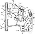
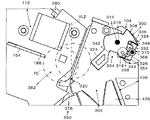
硬貨振分装置100は、同一の硬貨投入口108に投入された硬貨C(小径硬貨SC及び大径硬貨LCの総称)を正貨GC又は偽貨FCに識別し、偽貨FCは返却口110へ返却し、正貨GCたる小径硬貨SC又は大径硬貨LCを対応する小径硬貨通路112又は大径硬貨通路114に振り分ける機能を有し、大まかには図5に示すように、フロントパネル116、ベースボード118、ガイドボード120、及び、第2ガイドボード122を含んでいる。
硬貨選別装置102は、硬貨振分装置100によって振分られた小径硬貨SC又は大径硬貨LCを硬貨保留装置104によって金種別に所定数保留した後、それらが所定金額になった場合、受入処理し、又は、硬貨返却手段106が操作された場合、返却口110へ返却する機能を有する。
First, the
The
The
まずフロントパネル116を主に図1及び図7を参照して説明する。
フロントパネル116は、硬貨投入口108、返却口110、及び、返却レバ124が配置される機能、及び、硬貨振分装置100又は硬貨振分装置100を有する硬貨選別装置102が装着される機器、例えば、ゲーム機に取り付ける際の骨格機能を有し、本実施例においては、正面視矩形の基板126と樹脂製の化粧板128とより構成されている。
First, the
The
基板126は、ベースボード118と共に硬貨振分装置100及び硬貨選別装置102の骨格を構成する機能を有し、高強度を有する金属板や樹脂によって製造され、本実施例においては金属板によって縦長矩形に形成されている。
基板126には硬貨投入口108に対応して硬貨口130、返却口110に対応して返却開口132、返却レバ124に対応してレバ開口134が形成されている。
硬貨口130は、基板126の上部中央に縦長矩形に形成され、その縦横の大きさは、大径硬貨LC、本実施例においては10円硬貨10Cの直径及び厚みに対し僅かに大きい寸法に形成されている。したがって、縦又は横の寸法において、当該硬貨口130よりも大きい寸法を有する偽貨FCは、硬貨口130を通過できないので、硬貨Cは硬貨口130において大雑把に選別される。
返却開口132は、基板126の下部中央部に縦長矩形に形成された開口であり、後述の硬貨返却通路244に連なり、前方には返却硬貨保持体138が配置されている。
レバ開口134は、基板126の中間において正面視右側にオフセットした位置に形成された縦長矩形の開口であり、返却レバ124の中間が貫通する。
The
The
The
The
The
次ぎに化粧板128を説明する。
化粧板128は、顧客に対面する面であり、外観品質向上のため樹脂によって成型され、基板126よりも一回り大きい縦長矩形であって、垂立状態に配置され、硬貨投入口108、返却口110が配置され、返却レバ124が前方に突出する開口140が形成されている。硬貨投入口108は、縦長矩形であって、硬貨口130よりも僅かに大きく形成されると共に、正面視、硬貨口130に対し前側において重なった状態で隣接している。返却口110は縦長矩形であり、正面視、返却開口132に重なった状態で当該返却開口132に対し前側において隣接している。開口140は正面視、レバ開口134に重なった状態において前側に隣接配置されている。
化粧板128の下部から前方に向かって突出する返却硬貨保持体138は、硬貨返却通路244を転動してきた大径硬貨LC又は小径硬貨SCを大凡立った状態に保持する機能を有し、化粧板128の下部から前方に向かって突出する側面視三角形状の保持溝142を構成する。この構成によって、硬貨返却通路244から、返却開口132及び返却口110を通って返却硬貨保持体138に達した大径硬貨LC又は小径硬貨SCは、その左側面又は右側面がそれらの側壁にもたれ掛かった状態において、大凡垂立した状態で保持される。
Next, the
The
The
次ぎにベースボード118を主に図3及び図8を参照して説明する。
ベースボード118は、ガイドボード120、返却レバ124等が取りつけられる機能、及び、小径硬貨通路112の一側面を形成する機能を有し、本実施例においては、大凡台形の平板状体であり、例えば耐摩耗性を有する金属又は樹脂により成形される。
ベースボード118は、基板126に対し直角をなすように固定され、換言すれば、平面視、基板126と共にT字形を成すように固定されている。具体的には、その内側面118Aが硬貨口130の垂立右側壁130R、及び、返却開口132の垂立側壁132Rの延長上に配置される。したがって、ベースボード118は同様の機能を有する構成全てを含み、本実施例に限られるものではなく、少なくとも本実施例に開示された構成から当業者が推考しうる技術思想の範囲を含むものである。
ベースボード118の上部には、後述する保持体(図示されない)、第1軸受162Aと第2軸受162Bが横向き水平方向に突出形成されている。
Next, the
The
The
At the top of the
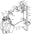
次に、ガイドボード120が主に図6、図7及び図9を参照して説明される。
ガイドボード120は、硬貨位置規制装置150、硬貨選別クレードル152、小径硬貨ガイドレール154、及び、第2ガイドボード122等が取りつけられ、さらに、ベースボード118と共同して小径硬貨通路112を画定する機能を有する。したがって、ガイドボード120は同様の機能を有する構成全てを含み、本実施例に限られるものではなく、少なくとも本実施例に開示された構成から当業者が推考しうる技術思想の範囲を含むものである。
ガイドボード120は台形状の平板であって、その上端部を着脱可能回動手段156によって、ベースボード118に対してその上端部を支点に回動可能かつ着脱可能に取り付けられ、静止状態においては、ベースボード118との対面する壁面が平行であって、硬貨Cの厚みよりも僅かに大きな間隔を開けて位置するよう配置されている。ガイドボード120を着脱可能にすることで小径硬貨通路112からの硬貨返却処理、当該小径硬貨通路112の清掃・メンテナンス等の便ためである。
本実施例における着脱可能回動手段156は、ガイドボード120の上端部に沿って斜めに固定された第1支軸158、中間を当該第1支軸158の中間に巻き付けられたバネ160、及び、ベースボード118の上端部側面に横向きに所定の間隔で突出形成された第1軸受162Aと第2軸受162Bによって構成されている。
第1支軸158は、第1軸受162Aと第2軸受162Bにそれぞれ形成された横向きの第1軸受溝164A、第2軸受溝164Bに回転自在に挿入されると共に、バネ160の中間から突出するU字形かつフック状に形成した係止部166をベースボード118の背面係止部118Bに係止することにより、ガイドボード120をベースボード118に対して回動自在に取りつけ、第1支軸158を中心に回動して当該ガイドボード120の下端部がベースボード118から離れ、小径硬貨ガイドレール154の側面がベースボード118から硬貨Cの厚みよりも僅かに大きく離れることが可能なように回動可能になっている。
Next, the
The
The detachable rotation means 156 in the present embodiment includes a
The
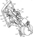
次ぎに第2ガイドボード122を主に図2、及び、図14を参照して説明する。
第2ガイドボード122は、硬貨選別クレードル152によって選別された正貨GCの大径硬貨LCが転動する大径硬貨通路114をガイドボード120と共に画定形成する機能を有し、大凡横向きのL字型の平板状をしている。第2ガイドボード122の上端部の図2において左右端部に形成された第3軸受168A及び第4軸受168Bが、ガイドボード120の中間部からフロントパネル116側へ向かって斜め上向きに当該ガイドボード120の面に対し並行に突出する第2支軸170Aと第3支軸170Bに回動自在に支持され、その下端部から横向きに突出する狭幅の突条、したがって、大径硬貨ガイドレール200の側面がガイドボード120の下端部から大径硬貨LCの厚み以上離れることが出来るように構成され、また、バネ(図示せず)によって、当該大径硬貨ガイドレール200の側面がガイドボード120に近づくように付勢され、当該大径硬貨ガイドレール200の側面がガイドボード120にに密着するように構成されている。
Next, the
The
ベースボード118とガイドボード120とによって、図6に示すように硬貨投入口108(硬貨口130)に連続して横向案内通路172、硬貨振分通路174及び小径硬貨通路112が順に形成される。また、ガイドボード120と第2ガイドボード122とによって、小径硬貨通路112に対するガイドボード120の反対側に大径硬貨通路114が形成される。
By the
次ぎに横向案内通路172を主に図6〜図9を参照して説明する。
横向案内通路172は、硬貨投入口108に投入され、硬貨口130を通過した硬貨Cが横方向に転動する通路であって、硬貨投入口108に連続して形成された大凡直線状の短い通路であり、硬貨投入口108に投入された硬貨Cを垂立状態で案内し、さらに、所定の速度範囲に揃える機能を有する。横向案内通路172は同様の機能を有する構成全てを含み、本実施例に限られるものではなく、少なくとも本実施例に開示された構成から当業者が推考しうる技術的思想の範囲を含むものである。本実施例において、横向案内通路172はベースボード118、ガイドボード120、横向案内通路ガイドレール176、及び、横向案内通路上側ガイドレール178によって構成された、断面形状及び寸法が硬貨口130と同様に縦長矩形に形成されると共にフロントパネル116から離れるにしたがって前下がりに傾斜する所定の長さの通路である。本実施例において横向案内通路ガイドレール176は、ガイドボード120と一体に形成され、その横幅W1は最厚の硬貨Cの厚みより僅かに大きく形成され、長さは大径硬貨LCの半径程度である。横向案内通路上側ガイドレール178は、ベースボード118の上端部から横向きに所定の幅で庇状に突出させることにより形成されている。さらに、横向案内通路上側ガイドレール178の後端部には、横向案内通路上側ガイドレール178の先端(フロントパネル116に対しては後端)から下向きに当該ガイドボード120と平行に垂下する保持体(図示されない)が形成されている。横向案内通路172は長いほど硬貨投入口108に投入された際の硬貨Cの勢い等を減衰させて転動速度を均一化できるので好ましいが、長すぎると装置自体が大型化するので、上記長さが好ましい。保持体とベースボード118との間隔は、静止状態にあるガイドボード120とベースボード118との間隔ど同一であり、下端部には横向通路偽貨選別磁石182が貫通するための円形の開口(図示されない)が形成されている。この保持体は、横向通路偽貨選別磁石182に吸着された偽貨FCを返却するため、ガイドボード120を第1支軸158回りに回動させた際、当該偽貨FCが一緒に移動しないよう移動を規制する作用をなす。
ガイドボード120には、保持体を収納するための凹溝181が形成されている。
Next, the
The
The
次ぎに横向通路偽貨選別磁石182を主に図9及び図10を参照して説明する。
横向通路偽貨選別磁石182は、横向案内通路172を転動する磁性体性の偽貨FCを吸着して硬貨振分通路174に達しないようにする機能を有し、本実施例においては横向案内通路172に相対するガイドボード120に円形の第1貫通孔183とスリ割り184を有する筒型の磁石ホルダ185が形成され、当該第1貫通孔183に丸棒状の横向通路偽貨選別磁石182を挿入し、その先端が硬貨振分通路174の側方、具体的には保持体の開口に臨んだ位置においてスリ割り184を締め付けることにより固定してある。
横向通路偽貨選別磁石182は同様の機能を有する構成全てを含み、本実施例に限られるものではなく、少なくとも本実施例に開示された構成から当業者が推考しうる技術的思想の範囲を含むものである。この構成によって、鉄製の偽貨FCが硬貨投入口108に投入された場合、硬貨振分通路174を転動する過程において、横向通路偽貨選別磁石182によって吸着されて保持され、選別される。ガイドボード120を第1支軸158回りに回動させた場合、横向通路偽貨選別磁石182はベースボード118から離れるが、当該横向通路偽貨選別磁石182によって吸着された偽貨FCは保持体によって移動を阻止されて一緒に移動できないので、ついには磁力により保持力よりも自重による落下力が上回り、後述の硬貨返却通路244に落下する。
Next, the horizontal passage false
The lateral passage false
The lateral passage false
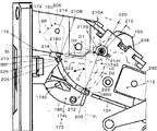
次ぎに硬貨振分通路174を主に図5を参照して説明する。
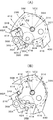
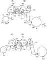
硬貨振分通路174は、横向案内通路172を転動した硬貨Cの真偽及び金種を判別するための硬貨選別クレードル152が配置され、小径硬貨SCと大径硬貨LCがそれぞれ当該硬貨振分通路174を落下する過程において、対応する小径硬貨通路112又は大径硬貨通路114に振り分けられる機能を有する。硬貨振分通路174は同様の機能を有する構成全てを含み、本実施例に限られるものではなく、少なくとも本実施例に開示された構成から当業者が推考しうる技術的思想の範囲を含むものである。本実施例において硬貨振分通路174は、ベースボード118とガイドボード120との間に形成され、横向案内通路172の下流側に連通する縦向きの通路、換言すれば、硬貨振分通路174は横向案内通路172に続いて上下方向に延在(垂立)する大径硬貨LC及び小径硬貨SCが落下する通路である。詳しくは、硬貨振分通路174は硬貨Cが垂下方向に移動する共通落下通路174C、小径振分通路174S及び大径振分通路174Lによって構成されている。共通落下通路174Cは、小径硬貨SC及び大径硬貨LCが硬貨選別クレードル152によって支持されて移動する通路である。換言すれば、後述の第2係止体210Bの移動に連動して小径硬貨SC及び大径硬貨LCが移動する通路、換言すれば、硬貨選別クレードル152のクレードル待受位置SBPから硬貨選別クレードル152が硬貨選別ストッパ228によって係止されるまでの範囲である。小径振分通路174Sは、共通落下通路174Cに続く小径硬貨通路112までの通路であり、本実施例においては硬貨選別クレードル152が硬貨選別ストッパ228に係止された第2係止体210Bの選別位置SSPでの通路である。換言すれば、小径振分通路174Sは、第1係止体210Aと選別位置SSPにおける第2係止体210Bとの間である。大径振分通路174Lは、硬貨選別クレードル152が硬貨選別ストッパ228に係止された選別位置SSPから大径硬貨通路114までの通路である。換言すれば、上部が共通落下通路174Cと重複し、下部が共通落下通路174Cの下方、かつ、硬貨投入口108側に位置すると共に、ガイドボード120に近づくように横方向に傾斜した通路である。本実施例において硬貨選別ストッパ228は、移動開口186の反硬貨投入口108側の壁面186Sである。しかし、硬貨選別ストッパ228は、移動開口186の壁面186Sに限定されるものではない。硬貨選別ストッパ228をガイドボード120の外面から突出させ、クレードルレバ222の中間を係止させることで、選別位置SSPを規制するようにしても良い。
Next, the
The
硬貨振分通路174の硬貨投入口108側には、硬貨Cの前側周面(硬貨投入口108側)及びベースボード118側側面を案内する移動ガイド202が配置されている。硬貨投入口108から遠い側には板状であって大凡垂立する後側ガイド205が配置されている。これら移動ガイド202及び後側ガイド205は大径振分通路174Lを画定する。
さらに、硬貨振分通路174、詳しくは大径振分通路174Lの側面に相対して、大径硬貨通路114に連通する側面視斜め下向き弧状の移動開口186が設けられている。したがって、硬貨振分通路174は、正面視、右側側面がベースボード118の内側面118A、左側側面がガイドボード120の内側面120A、前側側面が移動ガイド202、及び、後側側面が後側ガイド205によって画定された垂立する通路である。
On the
Further, a moving
次ぎに小径硬貨通路112を主に図6及び図7を参照して説明する。
小径硬貨通路112は、硬貨振分通路174において硬貨選別クレードル152によって正貨GCとして選別された小径硬貨SCが硬貨投入口108から遠ざかる方向に転動可能にする機能を有し、本実施例においては、ベースボード118、ガイドボード120、小径硬貨ガイドレール154によって構成された断面が縦長であって、硬貨振分通路174の下流側に連接し、硬貨投入口108から遠ざかる方向において前下がりの平板状の空間である。
小径硬貨通路112は同様の機能を有する構成全てを含み、本実施例に限られるものではなく、少なくとも本実施例に開示された構成から当業者が推考しうる技術的思想の範囲を含むものである。小径硬貨ガイドレール154は、ガイドボード120に形成された前下がりのスリット状のレール開口188から横向きに突出する細長板状体である。
図10に示すように、本実施例において、小径硬貨ガイドレール154は、断面がL字型に形成された金属製の小径レール体190の下端部に位置する横向きの狭幅部である。小径レール体190は、ガイドボード120の表側に第2貫通孔194を貫通するネジ192によってガイドボード120の表側に固定固定されている。これにより、小径硬貨ガイドレール154は、ガイドボード120の内面側中央において、図6に示すように、右肩下がりに傾斜するスリット状のレール開口188からベースボード118側に突出状態で構成されている。詳述すると、図10に示すように、小径硬貨ガイドレール154は硬貨投入口108側、したがって硬貨振分通路174側の先端部154Tが僅かに幅広に形成され、中間から下流端にかけては狭幅の狭幅部154Nに形成されている。換言すれば、小径硬貨通路112の下面は、最初は先端部154Tの上面によって、ベースボード118とガイドボード120の間の全面に形成されているが、途中からは狭幅部154Nによって形成されるため、小径硬貨ガイドレール154の幅が狭くなり、ベースボード118と狭幅部154Nとの間にはスリット状の隙間が形成されることから、正貨GCよりも所定値以上薄い偽貨FCは、当該隙間から落下させることで選別できるように構成されている。なお、小径レール体190は金属製に代えて耐摩耗性を有する樹脂製に変更することができ、ガイドボード120と一体に成形することもできる。また、硬貨投入口108に対する位置を調整するため、ネジ192の第2貫通孔194は長孔にすることが好ましい。
小径硬貨通路112に相対して速度調整磁石装置280が設けられている。小径硬貨SCの選別精度を高めるためである。
Next, the small-
The small-
The small-
As shown in FIG. 10, in this embodiment, the small-diameter
A speed
次ぎに速度調整磁石装置280を主に図3、6及び図7を参照して説明する。
速度調整磁石装置280は、小径硬貨通路112を転動する硬貨Cの速度、詳しくは小径硬貨SCの正貨GCの速度を所定の範囲に調整して小径硬貨ガイドレール154から落下する小径硬貨SCの落下位置を所定の位置に制御する機能を有する。速度調整磁石装置280は同様の機能を有する構成全てを含み、本実施例に限られるものではなく、少なくとも本実施例に開示された構成から当業者が推考しうる技術的思想の範囲を含むものである。本実施例において、速度調整磁石装置280は小径硬貨通路112を構成するガイドボード120側の側面に固定状態に配置された永久磁石282及び第1磁性体284を含んでいる。小径硬貨SCと実質同一の直径及び重さに形成した磁性材料よりなる偽貨FCを当該永久磁石282及び第1磁性体284の磁力による内部起電力によって、当該偽貨FCの転動速度を減速させ、後述の振分体350によって小径返却口382に案内することにより、正貨GCとして受け入れられないようにするためである。
速度調整磁石装置280は、小径硬貨通路112の側面に配置された一対のN極永久磁石282NとS極永久磁石282S、及び、第1磁性体284を含んでいる。一対のN極永久磁石282NとS極永久磁石282Sは、ベースボード118の外側面側であって、小径硬貨ガイドレール154の下流端部に相対し、小径硬貨SCのほぼ全面と相対するように形成された矩形の一対のN極保持穴286NとS極保持穴286Sに嵌合した状態で固定される。換言すれば、小径硬貨通路112に対し、N極永久磁石282NのN極とS極永久磁石282SのS極とが隣接した状態で対面するように配置されている。保持穴286に相対するガイドボード120には矩形の磁性体装着孔288が形成され、矩形の第2磁性体292が固定される。これにより、N極永久磁石282NとS極永久磁石282Sからの磁力線は小径硬貨通路112を横断して第2磁性体292内を透過することで、小径硬貨通路112に強力な磁束を形成する。
硬貨Cは金属であるため、当該磁束を通過する際、材質に応じた内部起電力を生じることから、小径硬貨通路112を転動する硬貨Cは減速される。したがって、正貨GCたる小径硬貨SCの転動速度を適当な速度に減速することにより、小径硬貨ガイドレール154から落下する硬貨Cの落下位置が決定される。
Next, the speed
The speed
The speed
Since the coin C is a metal, an internal electromotive force corresponding to the material is generated when passing through the magnetic flux, so that the coin C rolling in the small
この構成によって、小径硬貨ガイドレール154から落下する小径硬貨SCの位置は、小径硬貨通路112を転動する速度と硬貨重量に依存する慣性力によって定まる。換言すれば、小径硬貨SCが正貨GCである場合、小径硬貨ガイドレール154から落下する小径硬貨SCの慣性力はほぼ一定になる。したがって、本実施例においては正貨GCの小径硬貨SCの円周の最下端に対し図17に示すように後述する振分体350が左側に配置されていることから、正貨GCである場合は振分体350の右側へ案内され、所定の慣性力を持たない偽貨FCは左側へ案内される。
With this configuration, the position of the small-diameter coin SC falling from the small-diameter
次ぎに大径硬貨通路114を主に図14を参照して説明する。
大径硬貨通路114は、硬貨選別クレードル152によって正貨GCとして選別された大径硬貨LCがガイドボード120に形成された移動開口186を通った後、転動する通路であり、ガイドボード120、第2ガイドボード122、及び、大径硬貨ガイドレール200によって構成され、小径硬貨通路112に対しガイドボード120を挟んだ反対側であって、かつ、やや下方に配置された、断面が縦長矩形であって、硬貨投入口108から遠ざかるに従って前下がりの平板状の空間である。大径硬貨通路114は同様の機能を有する構成全てを含み、本実施例に限られるものではなく、少なくとも本実施例に開示された構成から当業者が推考しうる技術的思想の範囲を含むものである。大径硬貨ガイドレール200は、第2ガイドボード122の下端部からガイドボード120側に横向きに突出する細長突起状を呈し、その幅は大径硬貨LCたる10円硬貨10Cの厚みよりも僅かに大きく設定されている。これにより、大径硬貨ガイドレール200の側面がガイドボード120の外面に接することにより、大径硬貨通路114の幅が決定される。したがって、大径硬貨ガイドレール200は同様の機能を有する構成全てを含み、本実施例に限られるものではなく、少なくとも本実施例に開示された技術思想から当業者が推考しうる範囲を含むものである。
Next, the large-
The large-
次ぎに移動開口186を主に図11を参照して説明する。
移動開口186は、硬貨選別クレードル152によって、正貨GCとして選別された大径硬貨LCを硬貨振分通路174に対しベースボード118と反対側に配置された大径硬貨通路114に移動させるため、硬貨振分通路174と大径硬貨通路114とを連通する機能を有し、本実施例においては、硬貨振分通路174の下方において、ガイドボード120に形成された弧状の開口である。移動開口186は同様の機能を有する構成全てを含み、本実施例に限られるものではなく、少なくとも本実施例に開示された構成から当業者が推考しうる技術的思想の範囲を含むものである。移動開口186を形成するベースボード118側の上縁186Uの硬貨振分通路174側は面取を施し、硬貨振分通路174側に面する内向きの斜面203を形成し、さらに、下縁186Bの大径硬貨通路114側には外向斜面186Dを形成し、ガイドボード120に対し斜めになった大径硬貨LCがスムーズに移動できるようにすることが好ましい。しかし、これら斜面203及び外向斜面186Dは必須の構成要件ではない。また、移動開口186の形状は弧状に限定されないが、弧状にした場合、より小さいスペースにおいて大径硬貨LCが円滑に落下できるので好ましい。
Next, the moving
The moving
次ぎに移動ガイド202を主に図11を参照して説明する。
移動ガイド202は、正貨GCとして選別された大径硬貨LCが硬貨振分通路174から移動開口186を通って大径硬貨通路114へ移動するよう案内する機能を有し、本実施例においては、移動開口186の硬貨投入口108側に位置する縦向きの壁面によって構成されている。移動ガイド202は同様の機能を有する構成全てを含み、本実施例に限られるものではなく、少なくとも本実施例に開示された構成から当業者が推考しうる技術的思想の範囲を含むものである。
移動ガイド202は、側面案内壁202Sと周面案内壁202Pとによって形成されている.これら側面案内壁202Sと周面案内壁202Pは、ガイドボード120の硬貨投入口108側における上下方向の中間部からベースボード118側に突出し、ガイドボード120の内面側(すなわち、ベースボード118側)から視た場合五角形のガイド体204の反硬貨投入口108側の垂立面に形成され、横向案内通路ガイドレール176はガイド体204の上面によって構成されている。ガイド体204の突出量は、小径硬貨ガイドレール154の先端部154Tの幅と同一である。換言すれば、横向案内通路172、硬貨振分通路174、及び、小径硬貨通路112の厚みは同一であり、小径硬貨SC又は大径硬貨LCのうち、厚い方の厚みよりも僅かに幅広に形成されている。
また、前記内面側から視た場合、移動ガイド202の反硬貨投入口108側縁は三角形状に形成され、その頂部202Tは、小径硬貨通路112側に向かって凸型に形成されている。
Next, the
The
The
Further, when viewed from the inner surface side, the edge of the
まず側面案内壁202Sを説明する。
側面案内壁202Sは後述するように大径硬貨LCが硬貨選別クレードル152の第2係止体210Bとの接点を支点に自重によって回動した際、当該大径硬貨LCの硬貨投入口108側のベースボード118側の側面の一部を案内するよう頂部202Tから下方へ所定の幅で形成されると共に、下側ほど大径硬貨通路114に近づくように、換言すれば、下方ほどガイドボードに近づくように、さらに換言すればベースボード118から離れるように傾斜されている。したがって、側面案内壁202Sは硬貨Cの硬貨振分通路174を画定する。また、側面案内壁202Sは外向斜面186Dに滑らかに接続するように形成することが好ましい。
First, the
As will be described later, when the large-diameter coin LC is rotated by its own weight with a contact point with the
次ぎに周面案内壁202Pを説明する。
周面案内壁202Pは、硬貨選別クレードル152の第2係止体210B上を支点に回動した際、大径硬貨LCの周縁が描く円弧の僅か外側において円弧状に形成されている。換言すれば、周面案内壁202Pの上部は硬貨選別ストッパ228によって係止された状態にある第2係止体210Bとの接点を中心とする円弧状に形成されている。したがって、大径振分通路174Lは、前後が周面案内壁202Pと後側ガイド205によって画定され、側面がベースボード118及び側面案内壁202Sによって画定され、他方の側面が移動開口186によって開放されている通路である。したがって大径振分通路174Lは、上部は垂立するガイドボード120に対し平行であるが、下側はガイドボード120に対し交差するように傾いて形成される。
Next, the peripheral
The
次ぎに硬貨位置規制装置150を主に図6、図12及び図14を参照して説明する。
硬貨位置規制装置150は、横向案内通路172を転動してきた硬貨Cを所定位置に案内する機能を有する。所定位置とは、硬貨Cが最初に第2係止体210Bに接触する位置である。したがって、硬貨位置規制装置150は同様の機能を有する装置の全てを含み、本実施例に限られるものではなく、少なくとも本実施例に開示された構成から当業者が推考しうる技術的思想の範囲を含むものである。また、硬貨位置規制装置150は本発明の必須構成要素では無いが、硬貨振分機能及び硬貨選別機能の品質を安定させるには、装着することが好ましい。
本実施例において、硬貨位置規制装置150は、硬貨規制体206を含んでいる。
Next, the coin
The coin
In the present embodiment, the coin
硬貨規制体206は、横向案内通路172を転動した硬貨Cを、最初に硬貨選別クレードル152を構成する第1係止体210Aに、次いで、第2係止体210Bに密接させる機能を有する。
換言すれば、投入された硬貨Cを第1係止体210Aを構成する円筒体212の円弧周面212Sに押し付ける(密接させる)機能を有する。
したがって、硬貨規制体206は同様の機能を有する構成全てを含み、本実施例に限られるものではなく、少なくとも本実施例に開示された構成から当業者が推考しうる技術的思想の範囲を含むものである。本実施例における硬貨規制体206は、ガイドボード120のフロントパネル116の近くにおける外面側において、横向き水平に固定された第4支軸214に上端部が回動自在に支持された回動レバ216の先端がベースボード118側に折り曲げられ、かつ、水平に延在する棒状体218によって構成されている。棒状体218の先端は、ガイドボード120に形成され、移動開口186に連なる横向通孔219を通って横向案内通路172に突出している。硬貨規制体206は、上部が第4支軸214を中心とした半円状に形成され、当該上部から下端に向かって順次狭幅になる逆涙滴型に形成され、通常は自己モーメントが釣り合う待機位置SPにおいて静止状態を保っている。この待機位置SPにおいて、棒状体218は第4支軸214の大凡真下に位置し、第1係止体210Aの円弧周面212Sとの第1直線距離D1は、小径硬貨SCの直径よりも小さい。換言すれば、小径硬貨SC及び大径硬貨LCが第1係止体210Aの円弧周面212Sに接触した場合、棒状体218は当該硬貨Cによって図12において時計方向へ回動され、待機位置SPに戻ろうとするモーメントが発生する。硬貨Cが円弧周面212Sに接触していない場合、通常よりも一層大きなモーメントが発生するので、このモーメントによって、硬貨Cは円弧周面212S側へ移動されて当該円弧周面212Sに接触される。
硬貨規制体206の棒状体218の上面218Uは、横向案内通路ガイドレール176の延長上に形成された横向通孔219を通って横向案内通路172に突出し、横向案内通路ガイドレール176の延長線EL上に位置する。換言すれば、棒状体218は横向案内通路172の最下流の下縁を構成している。したがって、上面218Uは前下がりに傾斜する斜面に形成されている。しかし、上面218Uは極めて短いので、前下がり斜面では無く、水平面であっても良い。
また、大径硬貨LC又は小径硬貨SCは、硬貨規制体206と第1係止体210Aとによって挟まれるので、もし、それらの硬貨Cが勢いを付けて硬貨投入口108に投入され、周方向又は面方向に振動している場合であっても、硬貨規制体206と第1係止体210Aとによって挟まれることによってその振動が抑制された後、それぞれ第1係止体210A及び第2係止体210Bによって支持されるので、確実に保持される利点がある。
The
In other words, the inserted coin C has a function of pressing (in close contact) with the circular arc
Therefore, the
The
Further, since the large-diameter coin LC or the small-diameter coin SC is sandwiched between the
次ぎに硬貨選別クレードル152を主に図12〜図14を参照して説明する。
硬貨選別クレードル152は、小径硬貨SCと大径硬貨LCとを、主にそれらの直径によって、従的には重量も加えて正貨GCとして判別し、対応する小径硬貨通路112又は移動開口186を通って大径硬貨通路114へ振り分ける機能を有する。したがって、硬貨選別クレードル152は同様の機能を有する構成全てを含み、本実施例に限られるものではなく、少なくとも本実施例に開示された技術思想から当業者が推考しうる範囲を含むものである。
本実施例において硬貨選別クレードル152は、固定状態に配置された第1係止体210A、当該第1係止体210Aを中心として回動可能な第2係止体210B、第2係止体210Bが形成されたクレードルレバ222、及び、第1錘238を含んでいる。
Next, the
The
In this embodiment, the
第1係止体210Aは、投入された小径硬貨SC及び大径硬貨LCを第2係止体210Bと共同して支持し、かつ、支持した小径硬貨SCを共通落下通路174Cにおいて下方かつ硬貨投入口108から遠ざかる横方向へ移動させると共に、小径硬貨SCを当該横方向の延長上への移動を可能とし、及び、大径硬貨LCを移動ガイド202側へ移動可能にする機能を有する。したがって、第1係止体210Aは同様の機能を有する構成全てを含み、本実施例に限られるものではなく、少なくとも本実施例に開示された技術思想から当業者が推考しうる範囲を含むものである。第1係止体210Aを構成する円筒体212は、横向案内通路172の延長上のガイドボード120の内面から横方向に突出した状態で固定軸220によってガイドボード120に固定され、その突出量は横向案内通路ガイドレール176の横幅W1よりも僅かに小さく設定されている。詳細には、円筒体212は横向案内通路ガイドレール176の延長線ELの僅か上方に配置されている。また、円筒体212は、その一部を面取りした平坦部212Fが形成され、当該平坦部212Fは大凡下向きに配置され、後側ガイド205に対し大凡直角をなすように配置されている。平坦部212Fは、水平方向において、棒状体218の上面218Uと大凡同一の高さ位置に配置され、横向案内通路172、したがって、硬貨投入口108に対しては円弧周面212Sが相対するようその姿勢が定められている。硬貨規制体206の棒状体218が待機位置SPに位置する場合、当該棒状体218と円弧周面212Sとの第1直線距離D1は、小径硬貨SCの直径よりも僅かに小さく設定されている。小径硬貨SC及び大径硬貨LCが第1係止体210Aの円弧周面212Sに接触した後、第2係止体210Bに接触し、結果として第1係止体210A及び第2係止体210Bに載った状態で支持されるようにするためである。
硬貨選別クレードル152が回動され、第2係止体210Bが平坦部212Fと相対した場合、それらの間の第2直線距離D2は、第1直線距離D1よりも大きくなり、第1直線距離D1の場合には第1係止体210Aと第2係止体210Bによって支持された硬貨Cであっても、第2直線距離D2においては支持されなくなる。換言すれば、正貨GCである小径硬貨SC、本実施例においては100円硬貨100Cは、第2直線距離D2の場合には、第1係止体210Aと第2係止体210Bによって支持されないので、小径硬貨SCは、自身に作用するベクトル方向、換言すれば、本実施例においては横方向に位置する小径振分通路174S、したがって、小径硬貨通路112へ移動することができる。しかし、第2直線距離D2よりも直径が大きい大径硬貨LCは第1係止体210Aと第2係止体210Bによって支持されるので、大径硬貨LCに作用するベクトル方向には移動できない。換言すれば、大径硬貨LCは第1係止体210Aと第2係止体210Bとの間を通過できないので、小径振分通路174S、したがって小径硬貨通路112側には通り過ぎることができない。
本実施例のように、1つの円筒体212に形成された円弧周面212Sと、平坦部212Fとを用いて硬貨Cを選別することにより、設置スペースの削減による小型化、及び、部品点数削減によるコスト低減の利点がある。
The
When the
As in this embodiment, by selecting the coin C using the
次ぎに第2係止体210Bを説明する。
第2係止体210Bは、投入された硬貨Cを第1係止体210A(詳しくは円弧周面212S)と共同して支持し、かつ、支持した小径硬貨SCを当該小径硬貨SCに作用するベクトル方向へ移動させる機能、及び、大径硬貨LCを小径硬貨SCとは反対側へ移動させる機能を有する。
第2係止体210Bは、固定軸220のガイドボード120の表面側に突出する外向きの第2固定軸220Eに中間を回動自在に支持されたクレードルレバ222の先端部を直角に折り曲げ、ガイドボード120に形成された第2固定軸220Eを中心とする移動開口186の弧状の上縁186Uに近接した位置において、当該移動開口186を貫通して硬貨振分通路174、詳しくは共通落下通路174Cに突出している棒状の支え体226である。第1係止体210Aの円弧周面212Sと第2係止体210B、したがって、支え体226との第3直線距離D3は、小径硬貨SCの直径よりも僅かに小さく設定されている。小径の偽貨FCの排除のためである。クレードルレバ222の第2固定軸220Eよりも反第2係止体210B側へ延在するL字型に形成された第1錘238は、クレードルレバ222が通常は自己モーメントによって、待機位置SPに位置する棒状体218の直下に位置させるため、所定のモーメントを発生させる機能を有する。
クレードルレバ222は、通常、第1錘238のモーメントによって、図12において時計方向に回転され、ガイドボード120の外面側に突出された磁石ホルダ185の下側に形成された待機ストッパ239によって係止され、支え体226、すなわち、第2係止体210Bは棒状体218の直下に位置するクレードル待受位置SBPにおいて静止される。第2係止体210Bが待機位置SPに位置する場合、横向案内通路ガイドレール176上を転動してきた硬貨Cは、棒状体218の上面218Uを転動して最初に第1係止体210Aたる円弧周面212Sに衝突して横方向の運動エネルギが消滅させられ、その後の自重落下によって棒状体218を硬貨投入口108側へ移動させる。これにより、硬貨Cは硬貨位置規制装置150、すなわち、硬貨規制体206のモーメントによって第1係止体210A側へ押動されるから、確実に第1係止体210Aに接触される。その後、硬貨Cは第1係止体210Aとの接触状態を維持したまま落下するので、小径硬貨SC及び大径硬貨LCは第2係止体210Bによって支えられる。換言すれば、小径硬貨SC及び大径硬貨LCは、その周面が円弧周面212Sと接触させられるよりも早く第2係止体210Bに接触することは無い。これにより、硬貨選別クレードル152において、第1係止体210Aと第2係止体210Bとに支持されない状態において、クレードルレバ222が回動され、小径硬貨通路112又は大径硬貨通路114に案内されること、換言すれば、硬貨選別クレードル152によって直径に基づく真偽判別されない状態での硬貨Cの受入を防止できる利点がある。詳述すれば、横向案内通路ガイドレール176上を転動してきた硬貨Cは、棒状体218の上面218U上を転動した後、硬貨振分通路174、詳しくは共通落下通路174Cの上端に達し、最初に第1係止体210Aである円弧周面212Sに衝突して転動における横方向の慣性力を消滅させられるので、真下に落下する。これにより、硬貨Cは一周面を円弧周面212Sに接した状態で下方に落下するので、他方の周面は最初に棒状体218に接触し、硬貨規制体206を待機位置SPから硬貨投入口108側へ移動させ、さらに下方へ落下する。
次いで硬貨Cは第2係止体210Bに支持される。換言すれば、正貨GCである小径硬貨SC、及び、大径硬貨LCは第1係止体210A及び第2係止体210Bによって支持されるので、当該小径硬貨SC又は大径硬貨LCの重量によって、硬貨選別クレードル152、しがって、クレードルレバ222は図12において反時計方向へ回動される。クレードルレバ222が反時計方向へ回動された場合、第2係止体210Bは平坦部212Fに相対するようになるので、それらの間の直線距離は順次第1直線距離D1よりも増加し、ついには小径硬貨SCの直径よりも大きな第2直線距離D2になり、硬貨選別ストッパ228によって停止される。この選別位置SSPにおける第2係止体210Bの上面は、平坦部212Fと実質的に平行をなし、結果として、第1係止体210Aと第2係止体210Bとの第2直線距離D2は最も拡大する。また、第1係止体210Aと第2係止体210Bとの直線距離は、選別位置SSPに達する直前から小径硬貨SCの直径よりも大きい状態になる。したがって、第1係止体210Aと第2係止体210Bとの直線距離が小径硬貨SCの直径よりも大きくなった状況において、小径硬貨SCは第2係止体210Bと個別に移動可能であるが、実際には、第2係止体210Bが硬貨選別ストッパ228に係止されて選別位置SSPに静止した場合、小径硬貨SCは共通落下通路174Cを落下する際に作用する慣性力によって、当該落下時に描く円弧の法線方向へ移動する。すなわち、小径硬貨SCはその下端周面は第2係止体210Bによって支えられているが、上端周面は平坦部212Fから離れるので、自由移動が可能になることから、前記反時計方向の回動によって生じた接線方向の慣性力によって、自ら小径振分通路174S、すなわち、小径硬貨通路112に移動する。
第2係止体210Bの選別位置SSPにおいて、大径硬貨LCの直径は第1係止体210Aと第2係止体210Bとの第2直線距離D2よりも大いので、小径硬貨通路112へ移動することが出来ない。しかし、その状況において、大径硬貨LCの重心Gは、大径硬貨LCの下側周面と第2係止体210Bとの接点Pを通る垂線VLに対し硬貨投入口108側に位置するように設定されている。換言すれば、第2係止体210Bが選別位置SSPに位置する場合、大径硬貨LCは、第2係止体210Bとの接点Pを支点に、矢印で示す反小径硬貨通路112側、換言すれば、硬貨投入口108側へ自らの重量によって生じるモーメントによって、回動する。この際、大径硬貨LCの所定の重量が第2係止体210Bに作用している場合、当該重量によって第2係止体210Bは選別位置SSPを継続する。本実施例において、大径硬貨LCが第2係止体210Bに対して大凡10時の位置に落下するまで継続される。したがって、大径硬貨LCは前記接点Pを支点しての回動を継続することができる。この状況を第1係止体210Aと第2係止体210Bとの関係で規定した場合、第2係止体210Bは、第1係止体210Aに対し下方、かつ、硬貨投入口108側に配置される必要がある。
第2係止体210Bが選別位置SSPに位置する場合において、当該第2係止体210Bと第1係止体210Aとに係止された大径硬貨LCの硬貨投入口108側の縁は、頂部202Tよりも反硬貨投入口108側に位置するように設定されている。これにより、大径硬貨通路114を可及的に長く形成できるからである。
以上が本発明に係る実施例の硬貨振分装置100の構造の説明である。
Next, the
The
The
The
Next, the coin C is supported by the
At the sorting position SSP of the
When the
The above is the description of the structure of the
次ぎに、本硬貨振分装置100の作用を説明する。
まず、硬貨Cが硬貨投入口108に投入されると、硬貨Cは硬貨口130を通って横向案内通路172に達し、横向案内通路ガイドレール176の前下がりの傾斜によって横向案内通路172において硬貨投入口108から離れる方向に転動する。この転動の際、硬貨Cの左右側面は、ベースボード118の内側面118A及びガイドボード120の内側面120Aによって案内される。
この転動過程において、硬貨Cは横向案内通路ガイドレール176に続いて棒状体218の上面218Uを転動した後、自重により落下しつつ硬貨投入口108から離れる方向へ移動し、第1係止体210Aの円弧周面212Sに衝突し、横方向へのベクトルが消滅させられ、自重によって真下に落下する。
この真下に落下する際、小径硬貨SCであっても、棒状体218を硬貨投入口108側に押しやりながら落下するので、硬貨規制体206のモーメントによって棒状体218を介して硬貨Cに対し、第1係止体210A側へ押し付ける力が作用する。これによって、硬貨Cは確実に円弧周面212Sに接触させられる。硬貨Cがさらに落下すると、棒状体218の直下に位置する第2係止体210Bに支持される。硬貨Cの直径が第3直線距離D3よりも小さい場合、当該硬貨Cは第1係止体210Aと第2係止体210Bによっては支持されずにそれらの間を落下して後述の硬貨返却通路244に落下して返却される。
硬貨Cが第1係止体210Aと第2係止体210Bによって支持された場合、硬貨選別クレードル152(クレードルレバ222)は当該硬貨Cの重量によって第2固定軸220Eを支点に小径硬貨通路112側に向かって回動される。換言すれば、硬貨Cは第1係止体210Aと第2係止体210Bに支持されて共通落下通路174Cを落下しつつ硬貨投入口108から遠ざかる方向に第2固定軸220Eを中心として回動する。この回動の過程において、第2係止体210Bが平坦部212Fに徐々に相対することから、第2係止体210Bと第1係止体210A(平坦部212F)との間隔が徐々に大きくなり、ついには小径硬貨SCの直径よりも大きくなった後、第2係止体210Bは硬貨選別ストッパ228によって係止され、選別位置SSPに停止する(図12)。硬貨Cが正貨GCの小径硬貨SCである場合、当該小径硬貨SCは自己に作用する回動時の慣性力によって、第2係止体210B上から小径硬貨通路112へ移動する。小径硬貨SCが第2係止体210B上から移動した場合、硬貨選別クレードル152にはクレードル待受位置SBPへ指向する自己モーメントが作用するので、当該モーメントによって図11において時計方向へ回動され、待機ストッパ239に係止されてクレードル待受位置SBPに復帰する。なお、小径硬貨SCは、第2係止体210Bと第1係止体210Aとの距離がその直径以上になった場合、自由移動可能になるが、慣性力も相俟って、第2係止体210Bが選別位置SSPに停止されるまでは第2係止体210Bと一体的に移動する。
Next, the operation of the
First, when the coin C is inserted into the
In this rolling process, the coin C rolls on the
When falling directly below this, even if it is a small-diameter coin SC, it falls while pushing the rod-shaped
When the coin C is supported by the
硬貨Cが大径硬貨LCである場合、大径硬貨LCは選別位置SSPにおいて、第2係止体210Bのほぼ真上に位置するので、第2係止体210Bは選別位置SSPを継続する。大径硬貨LCは第1係止体210Aと第2係止体210Bとの間の第2直線距離D2よりも直径が大きいので、小径振分通路174S側へは移動でない。一方、大径硬貨LCの重心Gは、第2係止体210Bと大径硬貨LCとの接点Pを通る垂線VLに対し硬貨投入口108側に位置していることから、大径硬貨LCは接点Pを支点として硬貨投入口108側に回動しつつ落下する。大径硬貨LCの接点Pを支点とする回動によって、大径硬貨LCは硬貨投入口108側へ近づきつ落下する弧状軌跡を描いて落下する。換言すれは、大径硬貨LCは大径振分通路174Lを落下する。この落下の過程において、大径硬貨LCの硬貨投入口108側の端部は、移動ガイド202に進行する。移動ガイド202において、大径硬貨LCはその周縁近傍の側面は、移動開口186側へ順次近づく傾斜を有する側面案内壁202Sによって、また、周面は周面案内壁202Pに案内されつつ移動開口186側へ強制的に移動され、当該移動開口186を通って大径硬貨通路114へ移動される。
以上説明したように、本発明に係る硬貨振分装置100は、第1係止体210A、第2係止体210B、及び、移動ガイド202という簡単な構成によって、狭いエリアにおいて、、正貨GC若しくは偽貨FCに、そして正貨GCを小径硬貨SC若しくは大径硬貨LCとにそれぞれ振分けできる利点がある。
When the coin C is a large-diameter coin LC, the large-diameter coin LC is positioned almost immediately above the
As described above, the
次ぎに、前記硬貨振分装置100を備えた硬貨選別装置102を説明する。
硬貨選別装置102は硬貨振分装置100によって振分した小径硬貨SC及び大径硬貨LCを、所定数保留し、当該所定数になった場合、受け入れる機能を有し、本実施例においては、前記硬貨振分装置100に加え、少なくとも、硬貨返却手段106及び硬貨保留装置104、を含み、本実施例においては、更に、糸吊防止装置234、及び、硬貨受入信号出力のためのセンサ442を含んでいる。
Next, the
The
まず硬貨返却手段106を主に図1及び図3を参照して説明する。
硬貨返却手段106は、小径硬貨通路112、大径硬貨通路114、横向案内通路172、又は、硬貨振分通路174において詰まった硬貨C(正貨GC又は偽貨FC)、及び、硬貨保留装置104に保留された硬貨C(正貨GCの小径硬貨SC、並びに、大径硬貨LC)を硬貨返却通路244を経由して返却口110へ戻す機能を有する。本実施例において硬貨返却手段106は、返却レバ124、プレート押動体248、第1被動体252、第2被動体254、返却硬貨保持体138、及び、保留解除装置258を含んでいる。
First, the coin return means 106 will be described mainly with reference to FIGS.
The coin return means 106 includes a coin C (pure coin GC or fake coin FC) jammed in the
まず返却レバ124を説明する。
返却レバ124は、利用者によって操作された場合、ガイドボード120、をベースボード118に対し、及び、第2ガイドボード122をガイドボード120に対して回動させ、小径硬貨通路112又は大径硬貨通路114に保留され、又は、硬貨保留装置104の解除カム体466によって小径硬貨保留装置300及び大径硬貨保留装置302に保留されている小径硬貨SC、及び、大径硬貨LCを硬貨返却通路244に落下させる機能を有する。返却レバ124は、その先端がフロントパネル116の化粧板128に形成された開口140からフロントパネル116の前方へ突出し、その中間をフロントパネル116近傍のベースボード118の側面から横向き水平に突出する第3支軸262に回動自在に取り付けられると共に、返却レバ124に形成された突起265
に一端を係止され、他端を基板126から後方に向かって横向きに突出する突起264に係止した戻し用のスプリング266によって図3において時計方向への回動力を付与され、通常、約30度の上向き状態を呈した状態において、図示しないストッパによって係止されて静止状態を維持している。この状態が返却レバ124の返却待機位置RSPである。
First, the
When the
The locked one end, in FIG. 3 by a
次にプレート押動体248を説明する。
プレート押動体248は、返却レバ124のフロントパネル116に近い位置に一端を固定され、倒立L字型をし、先端部248T(図4)がほぼ水平にガイドボード120側に折り曲げられ、所定の幅を有している。換言すれば、先端部248Tは第1支軸158に対してずれていることから、当該先端部248Tが押された場合、ガイドボード120は第1支軸158回りに回動される。具体的には、返却レバ124が図3において反時計方向に回動された場合、プレート押動体248の先端部248Tは第3支軸262を中心とする円弧を描きながら下方へ移動し、この移動過程において、最初に第1被動体252を下方へ押動し、次ぎに第2被動体254を下方へ押動するように構成されている。
Next, the
The
次に第1被動体252を主に図9を参照して説明する。
第1被動体252は、返却レバ124の操作に基づいて移動するプレート押動体248(詳しくは先端部248T)によって押動される機能を有し、本実施例において、第1被動体252は、ガイドボード120のフロントパネル116側の端部の中間から横向きに突出した矩形の板状体であり、ベースボード118に形成された第3貫通孔268を通ってベースボード118に対し反対側である返却レバ124側に突出している。したがって、プレート押動体248の先端部248Tによって、第1被動体252が押し下げられた場合、第1支軸158を支点に正面視(フロントパネル116側から見て)時計方向へ回動され、結果として、ガイドボード120がベースボード118に対し傾斜することにより、その下端部がベースボード118から離れる。これにより、横向案内通路172において、横向通路偽貨選別磁石182によって吸着されている偽貨FCは、保持体によってその位置を規制された状態(横方向に移動できない)において、横向通路偽貨選別磁石182が当該偽貨FCから遠ざかるため、その磁力によって横向案内通路172に保持されなくなり、自重によって真下へ落下し、硬貨返却通路244を転動して返却口110へ戻される。
Next, the first driven
The first driven
次に第2被動体254を主に図7及び図14を参照して説明する。
第2被動体254は、返却レバ124の回動に伴って移動するプレート押動体248の先端部248Tによって押動され、第2ガイドボード122を第2支軸170A、第3支軸170Bを支点に回動させる機能を有し、本実施例においては、第2ガイドボード122のフロントパネル116側の端部の上端部から横向きに突出した矩形の板状体であり、ガイドボード120に形成された第3貫通孔268及びベースボード118に形成された第3貫通孔268を通ってベースボード118に対し反対側である返却レバ124側に突出している。第2被動体254は第1被動体252よりもフロントパネル116側に配置され、ている。
これにより、第1被動体252と第2被動体254は、通常、大凡近接して並列状態に静止され、返却レバ124が図3において反時計方向へ回動された場合、プレート押動体248の先端部248Tは図3において反時計方向へ回動されることにより、最初に第1被動体252を押し下げ、次いで当該第1被動体252と共に第2被動体254を押し下げる。
第1被動体252が押し下げられた場合、ガイドボード120は第1支軸158を支点に回動されるので、ガイドボード120に固定された横向通路偽貨選別磁石182はベースボード118から離れるが、当該横向通路偽貨選別磁石182に吸着された偽貨FCは、保持体に阻止されて横向案内通路172に留められる。結果として、横向通路偽貨選別磁石182の磁力によっては偽貨FCを横向案内通路172に保持出来なくなり、当該偽貨FCは自重によって下方へ落下し、後述する硬貨返却通路244を転動して返却口110を通過し、返却硬貨保持体138によって、立った状態で保持される。
第2被動体254が押し下げられると、第2ガイドボード122は、第2支軸170A、第3支軸170Bを支点にガイドボード120に対し正面視時計方向へ回動される。また、ガイドボード120の外面側に一端が固定され、他端が第2ガイドボード122に形成された透孔270を通って小径硬貨通路112の側面に位置する離隔体272が設けられている。これにより、硬貨Cが離隔体272に相対する位置において詰まった場合、換言すれば、硬貨Cが転動しなくなった場合、第2ガイドボード122の回動によって、当該離隔体272は相対的に小径硬貨通路112に突出することから、当該硬貨Cは詰まりを解消され、下方へ落下して硬貨返却通路244に達し、前述同様に返却口110を通って返却硬貨保持体138によって保持される。離隔体272は、後述の大径硬貨クレードル450に保持された大径硬貨LCの側面と相対する位置に突出するように配置されている。
Next, the second driven
The second driven
As a result, the first driven
When the first driven
When the second driven
次ぎに硬貨保留装置104を主に図17〜図20を参照して説明する。
硬貨保留装置104は、硬貨振分装置100によって正貨GCとして小径硬貨通路112又は大径硬貨通路114に振り分けられた小径硬貨SC及び大径硬貨LCをそれぞれ所定数保留し、少なくとも所定金額になった場合に受入れする機能を有し、好ましくは所定金額を保留する以前には保留した硬貨を返却口110に返却する機能を有することが好ましい。特に、電源を用いることなく異なる金種の硬貨それぞれを所定数保留し、受入れる機能を有する。更には、硬貨振分装置100において正貨GCとして振分された小径硬貨SCと大径硬貨LCをそれぞれ個別に所定数(金額)保留し、少なくとも受入れる機能を有する。
硬貨保留装置104は、小径硬貨SCとしての100円硬貨100Cを少なくとも所定数受入れ、好ましくは、更に返却する小径硬貨保留装置300、及び、大径硬貨LCとしての10円硬貨10Cを所定数保留し、少なくとも受入、好ましくは更に返却する大径硬貨保留装置302、及び、小径硬貨保留装置300、並びに、大径硬貨保留装置302の動きを規制する連携装置310を有する。
Next, the
The
The
まず小径硬貨保留装置300を図17、図18、及び図21を参照して説明する。
小径硬貨保留装置300は、小径硬貨通路112に配置され、小径硬貨SC、本実施例においては相対的に小径である100円硬貨100Cを一時的に保留し、相対的に大径である10円硬貨10Cともども所定数(所定金額)が保留された場合、それぞれ所定の小径正貨口304又は大径正貨口306から落下させる機能を有する。好ましくは、それぞれ所定数の小径硬貨SC又は大径硬貨LCが保留されない間は、それぞ硬貨返却通路244に落下させ得る機能を有することが好ましい。
小径硬貨保留装置300は、小径規制体308、小径保持体312、固定小径保持体320、及び、連携装置310を含んでいる。
First, the small-diameter
The small-diameter
The small-diameter
まず小径規制体308を説明する。
小径規制体308は、大径規制体386と共同して小径係止部324及び大径係止部390の位置を規制し、小径硬貨SCを小径硬貨通路112に保留し、当該保留を解除する機能を有し、本実施例においてはベースボード118の後端部上部から水平方向の横向き水平に突出する保留第1軸314に中間を回転自在に支持された円盤状の板状体である。
小径規制体308は、本実施例において、保留第1軸314に嵌合するために中心部に形成された円形の第1軸孔316、当該第1軸孔316の周囲に形成された大凡楕円形の第1動作連携部318、当該第1動作連携部318から所定角度離れて形成された第1被動カム328を含んでいる。
小径規制体308は、ベースボード118と後述の仕切板322の間に配置され、その厚みは小径硬貨SCの厚みよりも薄く設定されている。ベースボード118と仕切板322との間隔は、小径硬貨SCの厚みを超えると共に小径硬貨SCの厚みの二倍未満の範囲であるが、小径硬貨SCの厚みの1.1〜1.5倍の範囲が好ましい。
First, the small
The small
In this embodiment, the small-
次ぎに第1動作連携部318を説明する。
第1動作連携部318は、小径規制体308及び大径規制体386の保留第1軸314回りの回動位置を、連携装置310と共同して規制する機能を有し、本実施例においては、図17に示すように、第1軸孔316を中心とする扇形部の周縁の一部であって、後述の小径係止部324に対し大凡90度の位置に形成された扇形状の第1凸部326である。この第1凸部326に対し大凡90度の位置に第1被動カム328が形成され、当該第1被動カム328側の端面が第1保留規制部338であり、小径係止部324側の端面が第1復帰規制部340であり、第1凸部326の周面が第1連携阻止部344である。
Next, the first
The first
次ぎに第1被動カム328を説明する。
第1凸部326に対し、大凡90度の位置に末広がり形状の第2凸部330が形成され、この第2凸部330の外周面が、第1凸部326に近づくほど第1軸孔316から離れる漸増半径を有する第1被動カム328を構成する。
Next, the first driven
A second
次ぎに第1待機規制部336、第1保留規制部338、第1回動規制部342及び第1連携阻止部344を説明する。
第1待機規制部336、第1保留規制部338、第1復帰規制部340、第1回動規制部342及び第1連携阻止部344は、第1凸部326と第2凸部330との間に形成された第1凹部332、第1凸部326と小径係止部324との間に形成された第2凹部334を利用して構成される。しかし、本発明においては少なくとも、第1待機規制部336、第1保留規制部338、及び、第1連携阻止部344が形成されていれば良い。
小径規制体308は、本実施例のように小径係止部324が一体に構成されている場合であっても、保留第1軸314回りに小径硬貨SCの解除方向とは逆方向、具体的には図18において時計方向の所定のモーメントを有するように、第2錘346が固定されている。第2錘346に代えてバネ力を作用させても良い。
Next, the first
The first
Even if the small-
次ぎに第1待機規制部336を説明する。
第1待機規制部336は、連携装置310と連携して小径規制体308を第1待機位置SB1に静止させる機能を有する。したがって、前記機能と同一の機能を有すれば、本実施例に限定されることなく、第1待機規制部336に相当する。
第1待機規制部336は、第1軸孔316の軸心を中心とした所定の第1半径R1を有する第1仮想円VC1上において、第1軸孔316に対し半径方向に離れて位置する。本実施例において、第1待機規制部336は第2凸部330の第1凸部326に相対する端面であり、小径規制体308の周方向に延在する壁面である。第1待機規制部336が連携装置310の保留第1ストッパ348に係止された場合、小径保持体312は第1待機位置SB1に静止される。
したがって、小径硬貨SCが小径保持体312の小径係止部324に載った場合、小径規制体308は小径硬貨SCの重量によって図18において反時計方向へ回動される。
Next, the first
The first
The first
Accordingly, when the small-diameter coin SC is placed on the small-
次ぎに第1保留規制部338を説明する。
第1保留規制部338は、連携装置310と連携して小径保持体312を第1保留位置ST1(図21参照)に静止させる機能を有する。したがって、前記機能と同一の作用、効果を有すれば、本実施例に限定されることなく、第1保留規制部338に相当する。
第1保留規制部338は、第1軸孔316の軸心を中心とした第1仮想円VC1上において、第1軸孔316に対し半径方向に延在する壁面である。本実施例において、第1保留規制部338は第1凸部326の第2凸部330側の端面である。
第1保留規制部338が連携装置310の保留第1ストッパ348に係止された場合、小径保持体312は第1待機位置SB1よりも図18において反時計方向に回動された第1保留位置ST1(図21(A))に静止される。
したがって、小径規制体308が小径硬貨SCの重量によって図18において反時計方向へ回動された場合、第1保留規制部338が保留第1ストッパ348に係止されて第1保留位置ST1に静止されるので、小径保持体312(小径係止部324)と後述の振分体350との協働によって小径硬貨SCは、小径硬貨保留装置300において保留される(図21(A)参照)。なお、第1保留規制部338は、保留第1ストッパ348に接触した場合、当該保留第1ストッパ348による係止を解除するように、当該保留第1ストッパ348を第1凹部332の外方へ押動するカム形状に形成されている。
Next, the first
The first
The first
When the first
Therefore, when the small-
次ぎに第1回動規制部342を説明する。
第1回動規制部342は、保留した小径硬貨SCを開放する際、小径規制体308が所定量以上回動しないように規制する機能を有する。したがって、前記機能と同一の作用、効果を有すれば、本実施例に限定されることなく、第1回動規制部342に相当する。
本実施例において、第1回動規制部342は第1軸孔316の軸心を中心とした第1仮想円VC1上に位置する小径係止部324の第1凸部326側の端面である。
第1回動規制部342が連携装置310の保留第2ストッパ358に係止された場合、小径規制体308は第1解除位置RE1に静止される(図21(B)参照)。
したがって、小径規制体308が小径硬貨SCの重量によって図21(A)において第1保留位置ST1からさらに反時計方向へ回動された場合、小径係止部324が振分体350から小径硬貨SCの直径よりも僅かに離れた位置まで回動できるように規制し、保留された小径硬貨SCは小径規制体308と振分体350との間を通過して小径正貨口304から落下することができると共に、小径規制体308が自己のモーメントによって、第1待機位置SB1に復帰できるようにするためである。
Next, the first
The first
In the present embodiment, the first
When the first
Therefore, when the small-
次ぎに第1復帰規制部340を説明する。
第1復帰規制部340は、小径規制体308が自己のモーメントによって、第1解除位置RE1から第1待機位置SB1に復帰する際、連携装置310の姿勢を復帰させる機能を有し、本実施例においては、第1復帰規制部340が保留第2ストッパ358に当接した際、当該保留第2ストッパ358を第2凹部334の外方へ押し出すよう作用する形状に形成されている。
Next, the first
The first
次ぎに固定小径保持体320を説明する。
固定小径保持体320は、前述のように、小径係止部324と共に小径硬貨SCを小径硬貨通路112に保留する機能を有する。本実施例においては、さらに、小径硬貨通路112を転動してきた小径硬貨SCの転動速度によって正貨GCと偽貨FCとに選別する機能を有する。本実施例において、固定小径保持体320は振分体350が固定小径保持体320である。以下説明の便宜上、振分体350として主に図20を参照して説明する。
本実施例において振分体350は、横向き水平であって、実質的に固定状態に設けられた棒体376である。棒体376は、上端をベースボード118から横向きに水平に突出する第5支軸378に回動自在に取りつけられた揺動レバ380の下端部からベースボード118側に横向き水平に突出し、小径硬貨ガイドレール154の下流の小径硬貨通路112に突出している。
揺動レバ380の下端部側面には第3錘381が固定され、重力によって揺動レバ380が垂立するように構成される。しかし、揺動レバ380は、第5支軸378に対し揺動可能であるが、前記のように硬貨Cの転動速度の相違によって選別するため、その揺動角は極めて限定された範囲になるよう図示しないストッパにより規制され、当該規制された範囲において、垂立状態を保つように揺動可能である。しかし、前述のように揺動レバ380の揺動角は極めて限定されているので棒体376、したがって振分体350(固定小径保持体320)の位置は実質的に固定状態と捉えて差し支えない。
Next, the fixed
The fixed small-
In this embodiment, the distributing
A
振分体350(固定小径保持体320)は第1待機位置SB1に位置する小径保持体312との間の第4直線距離D4(図18)、及び、第1保留位置ST1に位置する固定小径保持体320との間の第5直線距離D5(図21(A))は、小径硬貨SCの直径、すなわち100円硬貨100Cの直径よりも小さい距離において横方向に配置される。
図21(A)に示すように、小径硬貨SCは小径保持体312の小径係止部324と固定小径保持体320によって左右の下部周面を支えられて小径硬貨通路112に保留される。
The distributing body 350 (fixed small diameter holder 320) is a fourth linear distance D4 (FIG. 18) between the
As shown in FIG. 21 (A), the small-diameter coin SC is retained in the small-
上記構造より、図17において、第1解除位置RE1に位置する小径保持体312と振分体350(固定小径保持体320)との間が小径正貨口304であり、振分体350の左側が小径返却口382である。
従って、小径硬貨SCたる100円硬貨100Cは、小径正貨口304から、偽貨FCは小径返却口382から重力によって落下する。
From the above structure, in FIG. 17, the small-diameter
Therefore, the small-diameter coin SC serving as a 100-yen coin 100C is, from the small-
次ぎに第1連携阻止部344が図18を参照して説明する。
第1連携阻止部344は、小径保持体312が第1待機位置SB1に位置する場合、大径硬貨保留装置302の第2解除位置RE2(図24(B)参照)への移動を阻止する機能を有する。換言すれば、小径硬貨保留装置300及び大径硬貨保留装置302が第1保留位置ST1及び第2保留位置ST2に位置する場合のみ、小径硬貨保留装置300及び大径硬貨保留装置302が第1解除位置RE1又は第2解除位置RE2へ移動することができるようにする機能を有する。
本実施例において、第1連携阻止部344は第1軸孔316、すなわち保留第1軸314を中心として第1仮想円VC1よりも大きな第2半径R2を有する第2仮想円VC2上に位置する第1凸部326の周面によって構成される。第1凸部326は、所定の角度αの範囲で形成されている。所定の角度αは、保留第1待機規制部336が保留第1ストッパ348に係止され、小径保持体312が第1待機位置SB1に位置している場合、保留第2ストッパ358は第1連携阻止部344に相対し、かつ、保留第1軸314から第1連携阻止部344よりも離れた外側に位置し、第1保留規制部338が保留第1ストッパ348に係止され、小径保持体312が第1保留位置ST1に位置する場合(図21(A))、保留第2ストッパ358が第1連携阻止部344との相対から外れて第2凹部334に相対する(図21(A))ように構成される。
これにより、保留第2ストッパ358が第1連携阻止部344又は後述の第2連携阻止部364に相対している間、保留第1ストッパ348が第1保留規制部338の係止を中止することは無い。換言すれば、小径保持体312、及び、大径規制体386が第1保留位置ST1、第2保留位置ST2に位置する場合、保留第2ストッパ358が第1連携阻止部344及び第2連携阻止部364に進行を阻止されずに移動(回動)できるので、小径保持体312、及び、大径規制体386は、第1解除位置RE1及び第2解除位置RE2へ移動することができる。
Next, the first
The first
In the present embodiment, the first
Accordingly, the holding
次に大径硬貨保留装置302を主に図22乃至図24を参照して説明する。
大径硬貨保留装置302は、大径硬貨通路114に配置され、大径硬貨LC、本実施例においては100円硬貨100Cに対し相対的に大径硬貨たる10円硬貨10Cを一時的に保留し、小径硬貨SCともども所定数(金額)が保留された場合、大径正貨口306に受け入れる機能を有する。さらに、所定数の硬貨Cが保留されない間は、それら硬貨Cを硬貨返却通路244に落下させて硬貨返却通路244を介して返却口110に返却できる機能を有することが好ましい。
大径硬貨保留装置302は、大径係止体384、大径規制体386、及び、連携装置310を含んでいる。
Next, the large-diameter
The large-diameter
The large-diameter
まず大径係止体384を説明する。
大径係止体384は、本実施例において保留第3軸388に上端部を回転自在に支持された細長のL型板状体である。
保留第3軸388は、ベースボード118の上端部後方部分から正面視左方向横向き水平に突出する固定軸である。大径係止体384の下端のL型に突出する先端が大径係止部390であり、大径硬貨通路114の下流端部に位置し、大径規制体386と共同して後述の第2待機位置SB2、第2保留位置ST2、及び、第2解除位置RE2をとることができる。
大径係止部390が第2待機位置SB2に位置する場合の大径硬貨ガイドレール200の下流端と大径係止部390との間の第4直線距離D4、及び、第2保留位置ST2に位置する場合の大径係止部390と大径硬貨ガイドレール200の下流端との第5直線距離D5との距離は、大径硬貨LCの直径よりも小さく設定されているので、大径硬貨LCはそれらの間を通過できず、大径硬貨通路114に保留される。しかし、大径係止体384が図24(A)において更に時計方向に回動した第2解除位置RE2においける大径係止部390と大径硬貨ガイドレール200の下流端との第6直線距離D6は、大径硬貨LCの直径よりも大きくなることから、大径硬貨LCは大径正貨口306から落下することができる(図24(B))。
First, the large-
The large-
Pending
The fourth linear distance D4 between the downstream end of the large-diameter
次ぎに大径規制体386を主に図23を参照して説明する。
大径規制体386は、小径規制体308と共同して小径係止部324及び大径係止部390の位置を規制し、大径硬貨LCを大径硬貨通路114に保留し、及び、当該保留を解除する機能を有し、本実施例においては、第2軸孔394の周囲に形成された大凡楕円形の第2動作連携部396、及び、第2被動カム398を含んでいる。
大径規制体386は、仕切板322の反ベースボード118側に配置され、大凡、三日月型をし、第2動作連携部396が形成されている。
なお保留第1軸314の先端は、ベースボード118から延在する軸受399(図2)によって軸受けされることにより両持ち支持されている。
Next, the large
The large
The large-
The front end of the holding
次ぎに第2動作連携部396を説明する。
第2動作連携部396は、大径規制体386の周縁の一部、換言すれば第2軸孔394を中心とする扇形の第3凸部404の周面であり、第2被動カム398に対し約90度の位置に形成されている。よって、第2被動カム398との間には第3凹部406が形成される。第2被動カム398は、大凡末広が形状に突出した凸部の外周縁であり、第2半径R2よりも外側位置に位置し、第2動作連携部396側に近づくほど第2軸孔394から遠ざかる曲線に形成されている。
第2被動カム398に対し、第2軸孔394を挟んだ反対側には係止突起400が形成さている。したがって、第2動作連携部396と係止突起400との間には、第4凹部408が形成されている。
本実施例において、第3凹部406又は第4凹部408を利用して、第2待機規制部412、第2保留規制部414、第2回動規制部416、第2連携阻止部364、及び、第2復帰規制部424が形成されている。具体的には、第2待機規制部412は第2軸孔394の軸心を中心とする第1半径R1と半径とする第1仮想円VC1上であって、第2被動カム398の第3凹部406に面し、かつ、半径方向に延在する端面である。
第2保留規制部414は、第1仮想円VC1上に位置し、第3凸部404の第2被動カム398側の端面であって半径方向に延在し、大径規制体386の保留第1軸孔316回りの回動の規制を受け、保留第1ストッパ348と接触した際、当該保留第1ストッパ348を第3凹部406から押し出すように斜面に形成されている。
第2回動規制部416は第1仮想円VC1上に位置し、係止突起400の第3凸部404側の半径方向に延在する端面であり、大径規制体386の必要以上の回動を阻止する。
第2復帰規制部424は第1仮想円VC1上に位置し、第3凸部404の係止突起400側の半径方向に延在する端面であり、保留第2ストッパ358と接触した際、当該保留第2ストッパ358を第4凹部408から押し出すように、斜面に形成されている。
第2連携阻止部364は、保留第1軸314をの軸心を中心とする第2半径R2を有する第2仮想円VC2上に位置する第3凸部404の外周面である。本発明においては少なくとも、第2待機規制部412、第2保留規制部414、及び、第2連携阻止部364が形成されていれば良い。
また、小径規制体308の第1待機規制部336、第1保留規制部338、第1回動規制部342及び第1連携阻止部344と、大径規制体386の第2待機規制部412、第2保留規制部414、第2回動規制部416、及び、第2連携阻止部364は、同位相になった場合、完全に又は大凡重なるように形成されている。換言すれば、第1動作連携部318と第2動作連携部396は同一形状に形成されている。
大径規制体386は、保留第1軸314の回りに大径硬貨LCの解除方向とは逆方向、図22において反時計方向のモーメントを有するように、第4錘418が固定されている。第4錘418に代えてバネによって上記モーメントを付与することもできる。
Next, the second
The second
A locking
In the present embodiment, using the
The second
The second
The second
The second
In addition, the first
The
次ぎにリンク装置426が主に図22を参照して説明される。
リンク装置426は、大径係止体384と大径規制体386とをリンク結合してそれらを連動させる機能を有する。
本実施例においてリンク装置426は、大径係止体384から横向き水平に突出する第3固定軸428に一端が回動自在に、他端が大径規制体386から横向きに突出する支軸432に回転自在に支持されたコンロッド434により構成されている。この構造により、大径規制体386の回動位置、すなわち、第2待機規制部412が保留第1ストッパ348に係止されている場合、大径係止体384を第2待機位置SB2に(図22)、第2保留規制部414が保留第1ストッパ348に係止されている場合、大径係止体384を第2保留位置ST2に(図24(A))、第2回動規制部416が保留第2ストッパ358に係止されている場合、大径係止体384を第2解除位置RE2(図24(B))に移動させる。
Next, the
The
次ぎに連携装置310を主に図19を参照して説明する。
連携装置310は、小径硬貨保留装置300、及び、大径硬貨保留装置302がそれぞれ第1保留位置ST1、及び、第2保留位置ST2になった場合、第1解除位置RE1、及び、第2解除位置RE2へ移動可能とする機能を有する。換言すれば、小径硬貨保留装置300、及び大径硬貨保留装置302に所定数(金額)の硬貨Cが保留されない場合、小径硬貨SC又は大径硬貨LCを受け入れないようにする機能を有する。
連携装置310は、前述した保留第1ストッパ348、保留第2ストッパ358、揺動体354及び保留第2軸368を含んでいる。
Next, the
When the small-diameter
The
まず保留第2軸368を図18及び図23を参照して説明する。
保留第2軸368は、正面視ベースボード118の左側において横向き水平に固定された丸棒状の軸であり、保留第1軸314に対し硬貨投入口108から遠い斜め下方に配置されている。
First, the holding
Hold the
次ぎに揺動体354を説明する。
揺動体354は、保留第1ストッパ348及び保留第2ストッパ358を保留第2軸368に対し平行に保持すると共にそれらを待機保留位置WSP又は解除位置REPに移動させる機能を有する。
揺動体354は、保留第1軸314側に向かって両端部が突出するチャンネル形に形成され、それら突出部の先端に保留第1ストッパ348、保留第2ストッパ358が水平横向きであって、保留第2軸368に平行に支持され、かつ、小径規制体308の第1動作連携部318、及び、大径規制体386の第2動作連携部396に相対する長さに形成されている。詳述すれば、揺動体354は正面視ベースボード118に対し左側に配置され、保留第1ストッパ348及び保留第2ストッパ358はその中間部を揺動体354の端部にそれぞれ固定され、小径規制体308、及び、大径規制体386の側方に位置するようそれらの長さが設定されている。
連携装置310は、図18における反時計回り、及び、図23における時計回りに回動した待機保留位置WSPと、逆方向に回動した解除位置REP(図21(B)、図24(B))に位置することができる。
連携装置310が待機保留位置WSPに位置する場合、保留第1ストッパ348は第1凹部332(図18)、及び、第3凹部406(図23(A))に位置し、第1待機規制部336又は第1保留規制部338、及び、第2待機規制部412又は第2保留規制部414に係止可能である。
通常状態において小径規制体308、及び、大径規制体386は、保留第1ストッパ348側に回動するモーメントを有するので、保留第1ストッパ348は第1待機規制部336、又は、第2待機規制部412を係止し、小径規制体308、及び、大径規制体386はそれぞれ第1待機位置SB1、又は、第2待機位置SB2において静止され、保留第2ストッパ358は第1連携阻止部344、又は、第2連携阻止部364に相対し、それらの位置以上に保留第1軸314側に回動できず、静止状態を呈する。
Next, the
The rocking
The
The
When the
In the normal state, the small-
保留第1ストッパ348が、第1保留規制部338、及び、第2保留規制部414を係止する場合、小径規制体308、及び、大径規制体386は、それぞれ第1保留位置ST1(図21(A))、及び、第2保留位置ST2(図24(A))に移動し、保留第2ストッパ358は第1連携阻止部344、及び、第2連携阻止部364とは相対しない、換言すれば、第1連携阻止部344、及び、第2連携阻止部364に相対する半径方向の延長上に保留第2ストッパ358は位置しない。これにより、保留第2ストッパ358は、それぞれ第2凹部334、及び、第4凹部408へ進行可能になる。一方、保留第1ストッパ348は第1保留規制部338、及び、第2保留規制部414から押されて保留第2軸368回りに回動され、解除位置REPへ移動される。換言すれば、保留第1ストッパ348は第1凹部332、第3凹部406から退出し、第1保留規制部338、又は、第2保留規制部414の係止を中止し、小径規制体308が第1解除位置RE1、大径規制体386が第2解除位置RE2へ回動可能になる。
When the holding
保留第1ストッパ348が解除位置REPへ移動した場合、その移動の原因となる小径規制体308、又は、大径規制体386は、第1保留位置ST1、又は、第2保留位置ST2に位置した直後に第1連携阻止部344、又は、第2連携阻止部364が保留第2ストッパ358に対し相対しなくなるので、実質的にそれら小径硬貨SCたる100円硬貨100C又は大径硬貨LCたる10円硬貨10Cが解除され、小径硬貨通路112又は大径硬貨通路114に実質的に保留されなくなる。
換言すれば、保留第2ストッパ358が第1連携阻止部344、又は、第2連携阻止部364に相対する場合、保留第2ストッパ358はそれらに阻止されて保留第1軸314側に近づくことはできず、保留第1ストッパ348は待機保留位置WSPに留められ、解除位置REPへ移動することができない。なお、保留第1ストッパ348が解除位置REPへ移動するきっかけとなる小径規制体308、又は、大径規制体386の回動の原因となる小径硬貨SC又は大径硬貨LCは、小径係止部324、又は、大径係止部390によって一瞬保留され、実質的には保留されないが、説明の便宜上、この場合も保留されるとして説明する。
さらに換言すれば、小径規制体308、又は、大径規制体386の何れか一つが第1待機位置SB1、又は、第2待機位置SB2に位置する場合、その他の小径規制体308、又は、大径規制体386は、第1保留位置ST1、又は、第2保留位置ST2に移動することはできるが、第1解除位置RE1、又は、第2解除位置RE2には移動できない。
硬貨Cの数を基準に説明すれば、小径硬貨SC、及び、大径硬貨LCがそれぞれ1つずつ保留されない場合、小径硬貨SC及び大径硬貨LCとも小径正貨口304又は大径正貨口306から落下することができない。
When the holding
In other words, when the holding
In other words, when any one of the small
The explanation will be based on the number of coins C. When one small-diameter coin SC and one large-diameter coin LC are not held one by one, both the small-diameter coin SC and the large-diameter coin LC are the small-
さらに、小径硬貨SCたる100円硬貨100Cが小径保持体312と固定小径保持体320(振分体350)とによって保留され、又は、大径硬貨LCたる10円硬貨10Cが大径係止体384と大径硬貨ガイドレール200とに保留されている場合において、硬貨返却手段106、具体的には返却レバ124を回動させることにより、ガイドボード120を第1支軸158、及び、第2ガイドボード122を第2支軸170A及び第3支軸170B回りに回動させると共に、小径規制体308及び大径規制体386をそれぞれ第1解除位置RE1(図21(B))、及び、第2解除位置RE2(図24(B))に移動させることにより、小径硬貨SC及び大径硬貨LCを硬貨返却通路244に落下させることで返却口110に返却することができる。
Furthermore, the 100-yen coin 100C, which is the small-diameter coin SC, is held by the small-
次ぎに大径硬貨クレードル450を主に図2及び図16を参照して説明する。
大径硬貨クレードル450は、大径硬貨LCの直径及び重量によって正貨GCと偽貨FCに選別する機能を有する。
したがって、大径硬貨クレードル450は同様の機能を有する構成の全てを含み、本実施例に限られるものではなく、少なくとも本実施例に開示された技術思想から当業者が推考しうる範囲を含むものである。
本実施例においては、大径硬貨クレードル450は、従来公知のクレードルを用いることにより、大径硬貨LC(10円硬貨10C)の直径及び重量を機械的手段により判別し、正貨GCと偽貨FCとに選別する機能を有する。
具体的には、大径硬貨LCの直径よりも僅かに小さい間隔で配置された第1爪452Aと第2爪452Bに保持された場合、大径硬貨クレードル450がその重量によって横方向へ転動され、大径硬貨LCを大径硬貨ガイドレール200へ案内する。
Next, the large-
The large-
Therefore, the large-
In this embodiment, the large-
Specifically, when held by the
本実施例の大径硬貨クレードル450は、移動開口186の直ぐ下流の大径硬貨通路114に配置されている。
大径硬貨クレードル450は、大凡楕円形の大径硬貨クレードル本体454、一対の第1爪452Aと第2爪452B、及び、所定のモーメントを付与する第5錘456を含んでいる。
大径硬貨クレードル450は、板金製であり、大径硬貨クレードル本体454の偏心位置において正面視第2ガイドボード122から左側(外面側)に水平に突出された第6支軸458に回転自在に支持されている。
第1爪452A及び第2爪452Bは、大径硬貨クレードル本体454から第6支軸458を挟んで反対方向に延在する一対の棒状体の先端部をベースボード118側に折り曲げて形成され、第2ガイドボード122にそれぞれ第6支軸458を中心に弧状に形成された長孔460A、460Bを通って移動開口186の直ぐ下方に位置する大径硬貨通路114に配置されている。
大径硬貨クレードル450は、大径硬貨LCが載置されない状態において、第5錘456によるモーメントによって図2において時計方向(図14、図16において反時計方向)のモーメントを受け、時計回りに回動されると共に、長孔460Bの上端縁たる第3ストッパ465に係止され、第3待機位置SP3に静止される。
大径硬貨LCが第1爪452A及び第2爪452Bに支持された場合、大径硬貨LCの重心が第6支軸458よりも第2爪452B側に移動することから、大径硬貨クレードル450のモーメントの方向が代わり、図16において時計方向へ転動し、ついには大径硬貨LC自身の転動力によって当該第2爪452B上から転げ落ちた後、大径硬貨ガイドレール200上を転動する。
正貨GCの大径硬貨LCよりも直径が小さい偽貨FCは、第1爪452A及び第2爪452Bによって支持されずにそれらの間を落下し、直下の大径偽貨落下口463から硬貨返却通路244に落下して返却口110に返却される。
The large-
The large-
The large-
The
The large-
When the large-diameter coin LC is supported by the
The fake coin FC having a diameter smaller than the large coin LC of the genuine coin GC falls between them without being supported by the
大径硬貨クレードル450に正貨GCの大径硬貨LCが保持された場合、当該大径硬貨LCの重量によって大径硬貨クレードル450は図2において反時計方向に転動され、大径硬貨LCの重心が第2爪452Bの外方(図2において左方)へ移動した場合、当該大径硬貨LCは自重による転動力によって転がって、第2爪452Bから斜め左下方へ落下する。
大径硬貨LCが第2爪452Bから落下した場合、第5錘456によるモーメントによって、大径硬貨クレードル450は第3待機位置SP3に戻される。
本発明において、大径硬貨クレードル450は必須の構成ではなく、削除することもできる。すなわち、移動開口186から落下した大径硬貨LCが大径硬貨ガイドレール200上を転動するように構成しても良い。
When the large-
When the large-diameter coin LC falls from the
In the present invention, the large-
次ぎに糸吊防止装置234を主に図7を参照して説明する。
糸吊防止装置234は、正貨GCたる小径硬貨SC又は大径硬貨LCに天蚕糸等の細いながらも強度の高い糸状体を結びつけて正貨GCの受入信号を出力する機器を誤作動させて硬貨受入信号ERSを不正に発信させる行為を防止する機能を有する。本実施例においては、小径正貨口304(図7)の下方に延在する小径正貨通路436に配置した水車状の羽根車438が糸吊防止装置である。羽根車438の回転軸439にはワンウエイクラッチ(図示せず)が設けられ、小径硬貨SCの落下方向の羽根車438の回転は可能であるが、逆に小径硬貨SCの引き上げ方向の移動によって羽根車438に逆方向の回転力が作用した場合、当該ワンウエイクラッチによって回転出来ないように構成されている。詳述すれば、羽根車438の複数枚の羽根の間に一枚の小径硬貨SCのみが1つずつ進入する。羽根車438に作用する小径硬貨SCの重量によって、羽根車438は回転されることから、小径硬貨SCは当該羽根車438を通過して小径正貨通路436の下端の小径硬貨落下口440から次工程、例えば、金庫(図示せず)に落下する。
羽根車438と小径硬貨落下口440との間の小径正貨通路436に、硬貨受入信号ERSを出力するセンサ442が配置され、当該センサ442からの硬貨受入信号ERSによって当該小径硬貨SCの受入に基づく処理、例えば、ゲーム機においてゲームを開始することができるようにする。本実施例においては、センサ442としてマイクロスイッチ444がベースボード118の下端部に固定され、その検知片446が小径硬貨落下口440の直上の小径正貨通路436に配置される。
したがって、羽根車438を通過した小径硬貨SCによって検知片446が押動され、当該押動によってマイクロスイッチ444が硬貨受入信号ERSを出力する。なお、検知片446は小径硬貨SCの落下を邪魔しないように、逃避動をした後、元の位置に復帰する。
Next, the yarn
The thread
A
Therefore, the
次ぎに硬貨返却通路244を主に図8を参照して説明する。
硬貨返却通路244は、硬貨選別クレードル152において選別された偽貨FC、すなわち、第1係止体210Aと第2係止体210Bとの間に保持されない小径の偽貨FCが落下し、また、小径硬貨通路112に保持された小径硬貨SC又は大径硬貨通路114に保留された大径硬貨LCが意図的に返却操作された場合、それら硬貨Cが落下し、前下がり、すなわち、返却口110に向かって前下がりに傾斜する返却底面448(図7)上を所定の間隔で垂立する左側壁451と右側壁としてのベースボード118によって案内されつつ転動して返却口110を通過し、最終的に返却硬貨保持体138に保持されて静止状態になる。
Next, the
In the
次ぎに保留解除装置258を主に図3及び図27を参照して説明する。
保留解除装置258は返却レバ124が操作された場合、硬貨保留装置104に保留された大径硬貨LC又は小径硬貨SCの保留状態を解除すると共に下方の硬貨返却通路244へ落下させる機能を有する。換言すれば、小径規制体308及び大径規制体386をそれぞれ第1強制返却位置(図示されない)及び第2強制返却位置(図示されない)へ強制的に移動させる機能を有し、本実施例においてはベースボード118から横向き水平に突出する第3固定軸462に回動自在に下端を支持された解除レバ464の上端に形成された円弧状の解除カム体466を含んでいる。解除カム体466の内面が駆動カム468であり、第3固定軸462を中心とする円弧状に形成され、解除レバ464が回動された場合、第1保留位置ST1に位置する小径保持体312又は第2保留位置ST2に位置する大径係止体384を強制的に第1強制返却位置又は第2強制返却位置へ移動させることにより、連携装置310による位置規制とは無関係に小径係止部324を第1待機位置SB1、又は、大径係止体384を第2待機位置SB2へ移動(実際は第1待機位置SB1又は第2待機位置SB2の僅かに手前であるが、実質的には同様の位置であるので「第1待機位置SB1」、「第2待機位置SB2」として説明する。)させ、かつ、ガイドボード120を第1支軸158回りに、及び、第2ガイドボード122を第2支軸170A、第3支軸170B回りに回動させて小径硬貨通路112及び大径硬貨通路114の底面を開放することにより、対応する小径硬貨SC又は大径硬貨LCを硬貨返却通路244に落下させ、返却口110へ返却する。本実施例において、解除レバ464の中間からフロントパネル116側に延在する被動レバ470が設けられ、その先端から横向きに突出する被動ピン472が返却レバ124の後端部に形成された駆動長孔474に挿入されている。これにより、返却レバ124が図3において反時計方向へ回動された場合、駆動長孔474によって被動ピン472が押されることによって、被動レバ470を介して解除レバ464は時計方向へ回動される。
一方、小径係止部324が第1保留位置ST1に位置する場合、又は、大径係止体384が第2保留位置ST2に位置する場合、小径係止部324と一体に回動する小径規制体308の第1被動カム328、又は、大径係止体384と一体的に回動する大径規制体386の第2被動カム398の一部は、解除カム体466の駆動カム468の弧状の回動経路MCと交差する。換言すれば、小径係止部324が第1保留位置ST1に位置、又は、大径係止体384が第2保留位置ST2に位置する場合、駆動カム468の回動によって、当該駆動カム468によって押動され、小径係止部324は図27(C)に示すように第1待機位置SB1へ回動され、小径保持体312(振分体350)と小径係止部324とによって保持されている小径硬貨SCは、その重心Gが、小径保持体312を通る第2垂線VL2よりもフロントパネル116側、換言すれば、小径返却口382側に移動され、当該小径返却口382から下方へ落下する。この際、ガイドボード120はその第1被動体252がプレート押動体248の先端部248Tによって押し下げられ、ガイドボード120の下端部がベースボード118から離れるので、一層落下し易くなる。
返却レバ124の押し下げが終了した場合、返却レバ124はスプリング266の弾発力によって返却待機位置RSPに戻され、したがって、解除カム体466も待機位置へ戻される。
さらに、小径規制体308及び大径規制体386も、それらに作用するモーメントによって、それぞれ第1待機位置SB1又は第2待機位置SB2に戻される。
Next, the
When the
On the other hand, when the small-
When the pressing of the
Further, the small
次ぎに本実施例の硬貨選別装置102の作用を図25乃至図27をも参照しつつ説明する。なお、硬貨振分装置100の作用の説明は前述したので、小径硬貨通路112、又は、大径硬貨通路114に振り分けされた以降の作用を説明する。
まず硬貨Cが硬貨投入口108に投入される前の待機状態について説明する。
小径規制体308は、図18において自己モーメントによって時計方向に回動され、第1待機規制部336が待機保留位置WSPに位置する保留第1ストッパ348によって係止され、また、大径規制体386は図22に示すように、第2待機規制部412が保留第1ストッパ348によって係止され、小径係止部324が第1待機位置SB1に、大径係止体384が第2待機位置SB2において静止している。これにより、小径規制体308と一体に形成された小径係止部324が小径硬貨通路112に位置し、その先端と小径保持体312との距離は、小径硬貨SCの直径よりも短い第4直線距離D4である(図25A)。一方、大径硬貨通路114には、大径規制体386にリンク装置426を介して連動する大径係止体384の大径係止部390が位置し、大径係止部390と大径硬貨ガイドレール200の下流端との第5直線距離D5は、大径硬貨LCの直径よりも短い(図25B)。
Next, the operation of the
First, a standby state before the coin C is inserted into the
Small size
次ぎに硬貨Cが投入されたケースを説明する。
最初に、小径硬貨SCであるに100円硬貨100Cが投入され、次いで大径硬貨LCである10円硬貨10Cが投入された事例を説明する。
小径硬貨SCは、前述のように小径硬貨通路112に案内され、小径硬貨ガイドレール154上を転動しつつ速度調整磁石装置280の磁力によって速度を調整(減速)された後、図17に示すように、当該小径硬貨ガイドレール154端から斜め右下方へ落下する。これにより、小径硬貨SCが正貨GCである場合には、速度調整磁石装置280によって所定範囲の速度に調整されていることから、小径硬貨SCは自身のの最下端部から左下側周面が振分体350に接触することから、小径係止部324側に案内され、結果として、振分体350(固定小径保持体320)と小径係止部324の下端部によって支持される。これにより、小径規制体308は小径硬貨SCの重量によって図17において反時計方向に回動され、第1保留規制部338が保留第1ストッパ348に係止されて第1保留位置ST1に保持される(図21A)。この状態において、小径係止部324の先端と小径保持体312(振分体350)との間隔は第5直線距離D5であり、小径硬貨SCたる100円硬貨100Cの直径よりも小さいので、小径硬貨SCは小径係止部324の先端部と小径保持体312との上に載った状態で小径硬貨通路112に保留される(図25C)。換言すれば、小径硬貨SCが小径硬貨保留装置300によって、小径硬貨通路112に保留される。なお、振分体350は微小角度揺動可能に構成されているので、小径硬貨SCはその逃げ動によって落下した衝突を緩衝され、短時間に静止状態になる。
小径規制体308が第1保留位置ST1に移動した場合であっても、保留第2ストッパ358は大径規制体386の第2連携阻止部364と相対しているので、保留第1ストッパ348は待機保留位置WSPに継続して留められる。
Next, a case where a coin C is inserted will be described.
First, a case will be described in which a 100-yen coin 100C is inserted into a small-diameter coin SC, and then a 10-
The small-diameter coin SC is guided to the small-
Even when the small-
次ぎに、小径硬貨SCに続いて大径硬貨LCたる10円硬貨10Cが投入される。
大径硬貨LCは前述のように、大径硬貨通路114において大径硬貨ガイドレール200上を転動し、大径硬貨通路114に位置する大径係止体384、従って、大径係止部390に突き当たる。これにより、大径係止体384は図22において時計方向へ回動されるので、リンク装置426を介して大径規制体386は図22において時計方向へ回動されるが、第2保留規制部414が保留第1ストッパ348に係止されるので、大径係止体384は第2保留位置ST2に保持される(図25D)。
したがって、大径硬貨LCは大径硬貨保留装置302によって大径硬貨通路114に保留される。
Next, a 10-
As described above, the large-diameter coin LC rolls on the large-diameter
Therefore, the large diameter coin LC is retained in the large
大径規制体386が第2保留位置ST2に移動した場合(図25D)、第2連携阻止部364は保留第2ストッパ358に相対しなくなるので、保留第1ストッパ348は第1保留規制部338及び第2保留規制部414によって押動され、待機保留位置WSPから解除位置REPに移動される。これにより、小径係止部324は小径硬貨SCの重量によって図25(C)に示す位置からさらに反時計方向へ回動され、第1解除位置RE1に移動(図26A)することから、小径硬貨SCは小径正貨口304から小径正貨通路436へ落下し、糸吊防止装置234における羽根車438を回動させ、次ぎにマイクロスイッチ444の検知片446を押し下げて後、小径硬貨落下口440から金庫(図示せず)等に落下する。検知片446の移動によって、マイクロスイッチ444は、硬貨受入信号ERSを出力する。一方、大径規制体386も図25(D)における位置からさらに時計方向へ回動可能になることから、大径硬貨LCの重力に基づく転動力によって、大径係止体384が時計方向へ回動されて第2解除位置RE2に移動する(図26B)ことから、大径硬貨LCは大径正貨口306から大径正貨通路392へ落下し、大径落下口393から金庫等に落下する。
When the large-
小径規制体308、及び、大径規制体386は、第1回動規制部342、又は、第2回動規制部416が保留第2ストッパ358に係止されるため、小径係止部324は第1解除位置RE1、大径係止部390は第2解除位置RE2を超えて回動することはできない。
小径係止部324に小径硬貨SCが作用しなくなった場合、小径規制体308は自己モーメントによって回動されるので、小径係止部324は第1待機位置SB1に、大径規制体386も自己モーメントによって回動されるので第2待機位置SB2に戻る(図25A、25B)。
この過程において、保留第2ストッパ358は第1復帰規制部340、又は、第2復帰規制部424によって押動されて解除位置REPへ移動される(図26C、図26D)。保留第2ストッパ358の解除位置REPへの移動に伴って保留第1ストッパ348は待機保留位置WSPへ回動するので、小径規制体308、及び、大径規制体386の第1待機規制部336、及び、第2待機規制部412を係合し結果として小径係止部324は第1待機位置SB1、大径係止体384は第2待機位置SB2に静止する。
The small
When the small-diameter coin SC no longer acts on the small-
In this process, hold the
次に一番目に大径硬貨LCが、二番目に小径硬貨SCが投入される事例を説明する。
大径硬貨LCは、大径硬貨ガイドレール200上を転動し、前述のように大径係止体384の大径係止部390によって転動を阻止される。
そして前述のように、第2保留規制部414が保留第1ストッパ348に係止され、大径硬貨LCは大径係止部390によって進行を阻止されて大径硬貨通路114に保留される(図24(A))。大径規制体386の回動によって、前述のように第2連携阻止部364は保留第2ストッパ358との相対位置から外れ、保留第2ストッパ358は第1連携阻止部344とのみ相対するのでするので、小径規制体308が第1保留位置ST1に移動された場合、大径規制体386は第2解除位置RE2へ回動可能になる。しかし、保留第2ストッパ358が第1連携阻止部344に相対しているので、保留第1ストッパ348は待機保留位置WSPを継続する。
次に小径硬貨SCが投入された場合、前述のように、小径硬貨SCは小径係止部324と固定小径保持体320によって、小径硬貨通路112に保留される(実際は一瞬)。そして、小径係止部324が第1保留位置ST1に位置した場合、第1連携阻止部344も保留第2ストッパ358との相対位置から外れる(図25C)。
これにより、第1連携阻止部344、及び、第2連携阻止部364が保留第2ストッパ358との相対位置から外れるので、保留第1ストッパ348は解除位置REPへ移動可能になる。そして保留された小径硬貨SCの重量によって小径係止部324が保留第1軸314回りに回動し、また、大径硬貨LCの重量によって大径係止体384、したがって、リンク装置426を介して大径規制体386が保留第1軸314回りに回動し、保留第1ストッパ348が第1保留規制部338、又は、第2保留規制部414によって押動されて解除位置REPへ移動されることから、小径係止部324は第1解除位置RE1、及び、大径係止体384は第2解除位置RE2へ回動され、大径硬貨LCが大径正貨口306から、小径硬貨SCが小径正貨口304から落下し、前述のように、小径硬貨SCと大径硬貨LCとの金種別の金庫に保管される。なお、小径硬貨SCと大径硬貨LCとは、一つの金庫に保管することもできる。
小径硬貨SC及び大径硬貨LCが落下した後、小径規制体308、及び、大径規制体386は前述のように、それぞれのモーメントによって第1待機位置SB1、及び、第2待機位置SB2へ戻される。
Next, a case where a large coin LC is inserted first and a small coin SC is inserted second will be described.
The large-diameter coin LC rolls on the large-diameter
As described above, the second
Next, when the small-diameter coin SC is inserted, as described above, the small-diameter coin SC is retained in the small-
As a result, the first
After the small-diameter coin SC and the large-diameter coin LC have fallen, the small-
受け入れすべき大径硬貨LCである10円硬貨10Cよりも所定量以上大径又は肉厚の偽貨FCは、硬貨口130にを通過できず、硬貨投入口108において選別される。
A fake coin FC having a diameter larger than a predetermined amount or thicker than a 10-
大径硬貨LCよりも小径であって、かつ、小径硬貨SCよりも大径である偽貨FCが投入された場合、硬貨選別クレードル152において、大径硬貨LCと同様に移動開口186に案内された後、大径硬貨クレードル450の第1爪452Aと第2爪452Bに保持されずに大径偽貨落下口463から硬貨返却通路244へ落下し、返却口110に戻される。
When a fake coin FC having a smaller diameter than the large diameter coin LC and a larger diameter than the small diameter coin SC is inserted, the
小径硬貨SCよりも小径の偽貨FCが投入された場合、硬貨選別クレードル152の第1係止体210Aと第2係止体210Bに保持されないので硬貨返却通路244に落下し、返却口110へ戻される。
When a fake coin FC having a diameter smaller than that of the small-diameter coin SC is inserted, it is not held by the
直径及び重量とも大径硬貨LCと同様であるが、磁性金属によって製造された偽貨FCが投入された場合、横向案内通路172を転動する過程において、横向通路偽貨選別磁石182に吸着され、当該横向案内通路172に滞留する。この場合、返却レバ124を押し下げてガイドボード120を第1支軸158回りに回動させ、保持体によって当該吸着された偽貨FCを横向通路偽貨選別磁石182から引き離すことにより、横向通路偽貨選別磁石182の吸着から解放して硬貨返却通路244へ落下させ、返却口110へ戻す。
The diameter and weight are the same as those of the large diameter coin LC, but when a false coin FC made of magnetic metal is inserted, it is attracted to the lateral passage false
次に直径及び重量とも小径硬貨SCと同様であるが、非着磁性金属により製造された偽貨FCを投入したケースを説明する。
当該偽貨FCは、前述同様に小径硬貨ガイドレール154上を転動して速度調整磁石装置280の側方に達する。この場合、当該偽貨FCは非着磁性からなるため、永久磁石282に吸着されることは無いが、永久磁石282による制動力が大きくなり、正貨GCの場合よりも大きく減速される結果、小径硬貨ガイドレール154から落下した後、図17に示すようにその下部右側周面が振分体350に衝突することから、当該振分体350の左側に位置する小径返却口382から硬貨返却通路244に落下して返却口110に戻される。
Next, a case will be described in which a fake coin FC, which is the same in diameter and weight as the small-diameter coin SC but is made of a non-magnetized metal, is inserted.
The false coin FC rolls on the small-diameter
G 重心
LC 大径硬貨
SC 小径硬貨
SB1 第1待機位置
ST1 第1保留位置
RE1 第1解除位置
SB2 第2待機位置
ST2 第2保留位置
SBP 待受位置
RE2 第2解除位置
100 硬貨振分装置
108 硬貨投入口
112 小径硬貨通路
114 大径硬貨通路
120 ガイドボード
124 返却レバ
152 硬貨選別クレードル
172 横向案内通路
174 硬貨振分通路
186 移動開口
202 移動ガイド
210A 第1係止体
210B 第2係止体
228 硬貨選別ストッパ
300 小径硬貨保留装置
302 大径硬貨保留装置
308 小径規制体
310 連携装置
314 保留第1軸
324 小径係止部
336 第1待機規制部
338 第1保留規制部
344 第1連携阻止部
348 保留第1ストッパ
354 揺動体
358 保留第2ストッパ
364 第2連携阻止部
368 保留第2軸
384 大径係止体
386 大径規制体
388 保留第3軸
390 大径係止部
412 第2待機規制部
414 第2保留規制部
426 リンク装置
G center of gravity
LC large coin
SC small coin
SB1 First standby position
ST1 First hold position
RE1 First release position
SB2 Second standby position
ST2 Second hold position
SBP standby position
RE2 Second release position
100 coin sorting device
108 coin slot
112 Small coin path
114 Large diameter coin passage
120 Guide board
124 Return lever
152 Coin sorting cradle
172 Horizontal guide passage
174 Coin sorting passage
186 Moving aperture
202 Movement Guide
210A 1st locking body
210B 2nd locking body
228 coin sorting stopper
300 small diameter coin holding device
302 Large diameter coin holding device
308 Small diameter regulator
310 Cooperation device
314
324 Small diameter locking part
336 First Standby Control Department
338 First Retention Control Department
344 First Cooperation Blocker
348 Hold first stopper
354 Oscillator
358 Hold second stopper
364 Second Cooperation Blocker
368 Hold second axis
384 Large diameter locking body
386 Large diameter regulator
388 Hold third axis
390 Large diameter locking part
412 Second Standby Control Department
414 Second Retention Control Department
426 Link device
Claims (5)
平板状のガイドボード(120)の一側に配置され、前記硬貨投入口(108)に続いて形成された横向案内通路(172)と、
前記横向案内通路(172)に続いて形成された上下方向に延びる硬貨振分通路(174)と、
前記ガイドボード(120)に対し前記硬貨振分通路(174)と同一側に設けられた前記小径硬貨通路(112)と、
前記ガイドボード(120)に対する前記小径硬貨通路(112)の反対側に配置された前記大径硬貨通路(114)と、
前記硬貨投入口(108)の下方において前記硬貨振分通路(174)に臨んで所定の間隔で配置された第1係止体(210A)と第2係止体(210B)とを含み、前記第1係止体(210A)と前記第2係止体(210B)は同心状態に配置されると共に、前記第2係止体(210B)は前記第1係止体(210A)の周囲を部分的に回動可能に配置され、前記第2係止体(210B)が待受位置(SBP)に位置する場合、前記第1係止体(210A)と前記第2係止体(210B)との距離は前記小径硬貨(SC)の直径よりも僅かに小さく設定され、前記小径硬貨(SC)又は大径硬貨(LC)を保持した際、それら小径硬貨(SC)又は大径硬貨(LC)の重量によって前記硬貨投入口(108)から遠ざかる方向に回動する前記第2係止体(210B)を備える硬貨選別クレードル(152)と、
前記硬貨選別クレードル(152)が所定量回動された場合、前記第2係止体(210B)との距離が前記小径硬貨(SC)の直径よりも大きいが、前記大径硬貨(LC)の直径よりも小さくなるよう設定された前記第1係止体(210A)と、
前記硬貨選別クレードル(152)の回動を、前記第1係止体(210A)と第2係止体(210B)との距離が前記小径硬貨(SC)の直径よりも大きくなった前記第2係止体(210B)の回動位置であって、かつ、前記大径硬貨(LC)の重心(G)が前記硬貨投入口(108)側であり、さらに、前記大径硬貨(LC)が自重により落下可能な位置において停止させる硬貨選別ストッパ(228)と、
前記硬貨選別ストッパ(228)の近傍の前記ガイドボード(120)に形成され、前記大径硬貨(LC)が通過可能であって、かつ、前記大径硬貨通路(114)に連通する移動開口(186)と、
前記硬貨選別クレードル(152)が前記硬貨選別ストッパ(228)に係止されて前記大径硬貨(LC)が自重によって落下する際、前記硬貨選別ストッパ(228)よりも前記硬貨投入口(108)側に配置され、前記自重によって落下する大径硬貨(LC)を前記移動開口(186)を通って前記大径硬貨通路(114)へ案内する移動ガイド(202)と
を設けたことを特徴とする硬貨振分装置。 Coin sorting device for guiding small-diameter coin (SC) and large-diameter coin (LC) inserted from the same vertically long coin insertion slot (108) to the corresponding small-diameter coin passage (112) or large-diameter coin passage (114) ( 100)
A lateral guide passage (172) disposed on one side of the flat guide board (120) and formed following the coin slot (108);
A coin distribution passage (174) extending in the vertical direction formed following the lateral guide passage (172);
The small diameter coin passage (112) provided on the same side as the coin distribution passage (174) with respect to the guide board (120);
The large-diameter coin path (114) disposed on the opposite side of the small-diameter coin path (112) with respect to the guide board (120);
The first locking body (210A) and the second locking body (210B) disposed at a predetermined interval facing the coin distribution path (174) below the coin insertion slot (108), The first locking body (210A) and the second locking body (210B) are arranged concentrically, and the second locking body (210B) is a part of the periphery of the first locking body (210A). When the second locking body (210B) is positioned at the standby position (SBP), the first locking body (210A) and the second locking body (210B) The distance is set slightly smaller than the diameter of the small diameter coin (SC), and when holding the small diameter coin (SC) or large diameter coin (LC), these small diameter coin (SC) or large diameter coin (LC) A coin sorting cradle (152) comprising the second locking body (210B) rotating in a direction away from the coin slot (108) by the weight of
When the coin sorting cradle (152) is rotated by a predetermined amount, the distance from the second locking body (210B) is larger than the diameter of the small diameter coin (SC), but the large diameter coin (LC) The first locking body (210A) set to be smaller than the diameter;
When the coin sorting cradle (152) is rotated, the distance between the first locking body (210A) and the second locking body (210B) is larger than the diameter of the small diameter coin (SC). The locking body (210B) is in a rotational position, the center of gravity (G) of the large-diameter coin (LC) is on the coin slot (108) side, and the large-diameter coin (LC) is A coin sorting stopper (228) that stops at a position where it can drop by its own weight;
A moving opening (formed on the guide board (120) in the vicinity of the coin sorting stopper (228), through which the large-diameter coin (LC) can pass and communicates with the large-diameter coin path (114) ( 186),
When the coin sorting cradle (152) is locked to the coin sorting stopper (228) and the large-diameter coin (LC) falls due to its own weight, the coin insertion port (108) is more than the coin sorting stopper (228). And a moving guide (202) for guiding the large-diameter coin (LC) falling by its own weight through the moving opening (186) to the large-diameter coin path (114). Coin sorting device.
前記小径硬貨(SC)、及び、前記大径硬貨(LC)の厚みより僅かに大きい間隔で垂直に対向配置した平板状のベースボード(118)とガイドボード(120)との間において、前記硬貨投入口(108)に続いて形成された横向案内通路(172)と、
前記横向案内通路(172)に続いて形成された上下方向に延びる硬貨振分通路(174)と、
前記硬貨振分通路(174)に連通し、前記ガイドボード(120)に対し前記硬貨振分通路(174)と同じ側に設けられた小径硬貨(SC)のための小径硬貨通路(112)と、
前記ガイドボード(120)に対し前記小径硬貨通路(112)の反対側に設けられ、前記ガイドボード(120)に取り付けられた第2ガイドボード(122)との間に形成された大径硬貨(LC)のための大径硬貨通路(114)と、
前記硬貨投入口(108)の下方において前記硬貨振分通路(174)に臨んで所定の間隔で配置された第1係止体(210A)と第2係止体(210B)とを含み、前記第1係止体(210A)と前記第2係止体(210B)は同心状態に配置されると共に、前記第2係止体(210B)は前記第1係止体(210A)の周囲を部分的に回動可能に配置され、前記第2係止体(210B)が待受位置(SBP)に位置する場合、前記第1係止体(210A)と前記第2係止体(210B)との距離は前記小径硬貨(SC)の直径よりも僅かに小さく設定され、前記小径硬貨(SC)又は大径硬貨(LC)を保持した際、それら小径硬貨(SC)又は大径硬貨(LC)の重量によって前記硬貨投入口(108)から遠ざかる方向に回動する前記第2係止体(210B)を備える硬貨選別クレードル(152)と、
前記硬貨選別クレードル(152)が所定量回動された場合、前記第2係止体(210B)との距離が前記小径硬貨(SC)の直径よりも大きいが、前記大径硬貨(LC)の直径よりも小さくなるよう設定された前記第1係止体(210A)と、
前記硬貨選別クレードル(152)の回動を、前記第1係止体(210A)と第2係止体(210B)との距離が前記小径硬貨(SC)の直径よりも大きくなった前記第2係止体(210B)の回動位置であって、かつ、前記大径硬貨(LC)の重心(G)が前記硬貨投入口(108)側であり、さらに、前記大径硬貨(LC)が自重により落下可能な位置において停止させる硬貨選別ストッパ(228)と、
前記硬貨選別ストッパ(228)の近傍の前記ガイドボード(120)に形成され、前記大径硬貨(LC)が通過可能なであって、かつ、前記大径硬貨通路(114)に連通する移動開口(186)と、
前記硬貨選別クレードル(152)が前記硬貨選別ストッパ(228)に係止されて前記大径硬貨(LC)が自重によって落下する際、前記硬貨選別ストッパ(228)よりも前記硬貨投入口(108)側に配置され、前記自重によって落下する大径硬貨(LC)を前記移動開口(186)を通って前記大径硬貨通路(114)へ案内する移動ガイド(202)と
を設けたことを特徴とする硬貨振分装置。 Coin sorting device for guiding small-diameter coin (SC) and large-diameter coin (LC) inserted from the same vertically long coin insertion slot (108) to the corresponding small-diameter coin passage (112) or large-diameter coin passage (114) ( 100)
Between the small-diameter coin (SC) and the flat base board (118) and the guide board (120) that are vertically opposed to each other with an interval slightly larger than the thickness of the large-diameter coin (LC), the coin A lateral guide passage (172) formed following the inlet (108);
A coin distribution passage (174) extending in the vertical direction formed following the lateral guide passage (172);
A small-diameter coin passage (112) for small-diameter coin (SC) provided on the same side as the coin-distribution passage (174) with respect to the guide board (120), communicating with the coin distribution passage (174). ,
A large-diameter coin formed between the guide board (120) and a second guide board (122) provided on the opposite side of the small-diameter coin passage (112) and attached to the guide board (120). Large diameter coin passage (114) for LC),
The first locking body (210A) and the second locking body (210B) disposed at a predetermined interval facing the coin distribution path (174) below the coin insertion slot (108), The first locking body (210A) and the second locking body (210B) are arranged concentrically, and the second locking body (210B) is a part of the periphery of the first locking body (210A). When the second locking body (210B) is positioned at the standby position (SBP), the first locking body (210A) and the second locking body (210B) The distance is set slightly smaller than the diameter of the small diameter coin (SC), and when holding the small diameter coin (SC) or large diameter coin (LC), these small diameter coin (SC) or large diameter coin (LC) A coin sorting cradle (152) comprising the second locking body (210B) rotating in a direction away from the coin slot (108) by the weight of
When the coin sorting cradle (152) is rotated by a predetermined amount, the distance from the second locking body (210B) is larger than the diameter of the small diameter coin (SC), but the large diameter coin (LC) The first locking body (210A) set to be smaller than the diameter;
When the coin sorting cradle (152) is rotated, the distance between the first locking body (210A) and the second locking body (210B) is larger than the diameter of the small diameter coin (SC). The locking body (210B) is in a rotational position, the center of gravity (G) of the large-diameter coin (LC) is on the coin slot (108) side, and the large-diameter coin (LC) is A coin sorting stopper (228) that stops at a position where it can drop by its own weight;
A moving opening formed in the guide board (120) in the vicinity of the coin sorting stopper (228), through which the large-diameter coin (LC) can pass and communicates with the large-diameter coin passage (114). (186)
When the coin sorting cradle (152) is locked to the coin sorting stopper (228) and the large-diameter coin (LC) falls due to its own weight, the coin insertion port (108) is more than the coin sorting stopper (228). And a moving guide (202) for guiding the large-diameter coin (LC) falling by its own weight through the moving opening (186) to the large-diameter coin path (114). Coin sorting device.
前記ガイドボード(120)に対し前記ベースボード(118)の反対側に、前記ガイドボード(120)に対し回動可能に支持されると共に前記大径硬貨(LC)用の第2ガイドボード(122)が配置され、
返却レバ(124)の操作に連動して最初に前記ガイドボード(120)を回動させて当該ガイドボード(120)の下端を前記ベースボード(118)から離隔して前記小径硬貨通路(112)の下端部を開放させた後、前記第2ガイドボード(122)を前記ガイドボード(120)に対し回動させて当該第2ガイドボード(122)の下端を前記ベースボード(118)から離隔して前記大径硬貨通路(114)を開放させる硬貨返却手段(106)を設けたことを特徴とする請求項2に記載の硬貨振分装置。 The guide board (120) is rotatable at an upper end with respect to the base board (118) and is urged to approach the base board (118) side, and the small diameter coin passage (112). A guide rail (154) for the small-diameter coin (SC) for defining
A second guide board (122) for the large-diameter coin (LC) is supported on the opposite side of the base board (118) with respect to the guide board (120) so as to be rotatable with respect to the guide board (120). ) Is placed,
In conjunction with the operation of the return lever (124), the guide board (120) is first rotated to separate the lower end of the guide board (120) from the base board (118) and the small diameter coin passage (112). The lower end of the second guide board (122) is rotated relative to the guide board (120) to separate the lower end of the second guide board (12 2 ) from the base board (118). The coin distribution device according to claim 2, further comprising coin return means (106) for opening the large-diameter coin passage (114).
平板状のガイドボード(120)の一側に配置され、縦長の硬貨投入口(108)に続いて形成された横向案内通路(172)と、
前記横向案内通路(172)に続いて形成された上下方向に延びる硬貨振分通路(174)と、
前記ガイドボード(120)に対し前記硬貨振分通路(174)と同一側に設けられた前記小径硬貨通路(112)と、
前記ガイドボード(120)に対する前記小径硬貨通路(112)の反対側に配置された前記大径硬貨通路(114)と、
前記硬貨投入口(108)の下方において前記硬貨振分通路(174)に臨んで所定の間隔で配置された第1係止体(210A)と第2係止体(210B)とを含み、前記第1係止体(210A)と前記第2係止体(210B)は同心状態に配置されると共に、前記第2係止体(210B)は前記第1係止体(210A)の周囲を部分的に回動可能に配置され、前記第2係止体(210B)が待受位置(SBP)に位置する場合、前記第1係止体(210A)と前記第2係止体(210B)との距離は前記小径硬貨(SC)の直径よりも僅かに小さく設定され、前記小径硬貨(SC)又は大径硬貨(LC)を保持した際、それら小径硬貨(SC)又は大径硬貨(LC)の重量によって前記硬貨投入口(108)から遠ざかる方向に回動する前記第2係止体(210B)を備える硬貨選別クレードル(152)と、
前記硬貨選別クレードル(152)が所定量回動された場合、前記第2係止体(210B)との距離が前記小径硬貨(SC)の直径よりも大きいが、前記大径硬貨(LC)の直径よりも小さくなるよう設定された前記第1係止体(210A)と、
前記硬貨選別クレードル(152)の回動を、前記第1係止体(210A)と前記第2係止体(210B)との距離が前記小径硬貨(SC)の直径よりも大きくなった前記第2係止体(210B)の回動位置であって、かつ、前記大径硬貨(LC)の重心(G)が前記硬貨投入口(108)側であり、さらに、前記大径硬貨(LC)が自重により落下可能な位置において停止させる硬貨選別ストッパ(228)と、
前記硬貨選別ストッパ(228)の近傍の前記ガイドボード(120)に形成され、前記大径硬貨(LC)が通過可能であって、かつ、前記大径硬貨通路(114)に連通する移動開口(186)と、
前記硬貨選別クレードル(152)が前記硬貨選別ストッパ(228)に係止されて前記大径硬貨(LC)が自重によって落下する際、前記硬貨選別ストッパ(228)よりも前記硬貨投入口(108)側に配置され、前記自重によって落下する大径硬貨(LC)を前記移動開口(186)を通って前記大径硬貨通路(114)へ案内する移動ガイド(202)と、
前記小径硬貨通路(112)に配置され、前記小径硬貨(SC)を保留しない第1待機位置(SB1)と前記小径硬貨(SC)を保留する第1保留位置(ST1)及び保留した前記小径硬貨(SC)を解除する第1解除位置(RE1)をとり得る小径硬貨保留装置(300)と、
前記大径硬貨通路(114)に配置され、前記大径硬貨(LC)を保留しない第2待機位置(SB2)と前記大径硬貨(LC)を保留する第2保留位置(ST2)及び保留した前記大径硬貨(LC)を解除する第2解除位置(RE2)をとり得る大径硬貨保留装置(302)と、
前記小径硬貨保留装置(300)が前記第1保留位置(ST1)に位置する場合、前記大径硬貨保留装置(302)を前記第2保留位置(ST2)をとることは可能であるが、前記第2解除位置(RE2)への移動を不能とし、前記大径硬貨保留装置(302)が前記第2保留位置(ST2)に位置する場合、前記小径硬貨保留装置(300)を前記第1保留位置(ST1)をとることは可能であるが、前記第1解除位置(RE1)への移動を不能とし、かつ、前記小径硬貨保留装置(300)及び前記大径硬貨保留装置(302)が共に前記第1保留位置(ST1)、前記第2保留位置(ST2)になった場合、前記第1解除位置(RE1)又は前記第2解除位置(RE2)へ移動可能とする連携装置(310)と、
を有することを特徴とする硬貨振分装置を備えた硬貨選別装置。 Coin distribution device (100) for guiding small-diameter coin (SC) and large-diameter coin (LC) inserted from the same coin insertion slot (108) to corresponding small-diameter coin passage (112) or large-diameter coin passage (114) In
A lateral guide passage (172) disposed on one side of the flat guide board (120) and formed following the vertically long coin slot (108),
A coin distribution passage (174) extending in the vertical direction formed following the lateral guide passage (172);
The small diameter coin passage (112) provided on the same side as the coin distribution passage (174) with respect to the guide board (120);
The large diameter coin passage (11 4 ) disposed on the opposite side of the small diameter coin passage (112) with respect to the guide board (120);
The first locking body (210A) and the second locking body (210B) disposed at a predetermined interval facing the coin distribution path (174) below the coin insertion slot (108), together with the first locking body (210A) the second engaging member (210B) is arranged in concentric, the periphery of the second engaging member (210B) said first engaging member is (210 a) When the second locking body (210B) is located at the standby position (SBP), the first locking body (210A) and the second locking body (210B) Is set slightly smaller than the diameter of the small diameter coin (SC), and when holding the small diameter coin (SC) or large diameter coin (LC), the small diameter coin (SC) or large diameter coin (LC ) A coin sorting cradle (152) provided with the second locking body (210B) that rotates in a direction away from the coin slot (108) by the weight of
When the coin sorting cradle (152) is rotated by a predetermined amount, the distance from the second locking body (210B) is larger than the diameter of the small diameter coin (SC), but the large diameter coin (LC) The first locking body (210A) set to be smaller than the diameter;
The rotation of the coin sorting cradle (152), the distance between the first engaging member (210A) and said second engaging member (210B) is greater than the diameter of the small diameter coin (SC) first 2 is a rotational position of the locking body (210B), and the center of gravity (G) of the large-diameter coin (LC) is on the coin slot (108) side, and further, the large-diameter coin (LC) A coin sorting stopper (228) that stops at a position where it can fall by its own weight,
A moving opening (formed on the guide board (120) in the vicinity of the coin sorting stopper (228), through which the large-diameter coin (LC) can pass and communicates with the large-diameter coin path (114) ( 186),
When the coin sorting cradle (152) is locked to the coin sorting stopper (228) and the large-diameter coin (LC) falls due to its own weight, the coin insertion port (108) is more than the coin sorting stopper (228). A moving guide (202) disposed on the side and guiding the large-diameter coin (LC) falling by its own weight through the moving opening (186) to the large-diameter coin path (114);
A first standby position (SB1) that is disposed in the small-diameter coin path (112) and does not retain the small-diameter coin (SC), a first retention position (ST1) that retains the small-diameter coin (SC), and the small-diameter coin retained. a small-diameter coin holding device to obtain first take release position (RE1) to release the (SC) (300),
A second standby position (SB2) that is disposed in the large-diameter coin passageway (114) and that does not retain the large-diameter coin (LC), a second retention position (ST2) that retains the large-diameter coin (LC), and is retained. wherein the large diameter coin second release position for releasing the (LC) can take (RE2) large-diameter coin holding device (302),
When the small-diameter coin retaining device (300) is located at the first retaining position (ST1), the large-diameter coin retaining device (302) can take the second retaining position (ST2). When the movement to the second release position (RE2) is disabled and the large-diameter coin holding device (302) is located at the second holding position (ST2), the small-diameter coin holding device (300) is moved to the first holding position. It is possible to take the position (ST1), but the movement to the first release position (RE1) is disabled, and both the small diameter coin retaining device (300) and the large diameter coin retaining device (302) A linkage device (310) that is movable to the first release position (RE1) or the second release position (RE2) when the first hold position (ST1) and the second hold position (ST2) are reached ; ,
A coin sorting device provided with a coin sorting device.
前記大径硬貨保留装置(302)は、前記保留第1軸(314)の軸心に対し同一円上に形成された第2待機規制部(412)と第2保留規制部(414)、及び、第2連携阻止部(364)を含む大径規制体(386)と、一端部が保留第3軸(388)に回動自在に取付られると共に他端部が前記大径硬貨通路(114)に位置して前記大径硬貨(LC)を保持する大径係止部(390)を有する大径係止体(384)と、前記大径規制体(386)と前記大径係止体(384)とをリンク結合するリンク装置(426)とを含み、
前記連携装置(310)は、中間を保留第2軸(368)に回動自在に支持された揺動体(354)の一端部に設けられた保留第1ストッパ(348)及び他端部に設けられた保留第2ストッパ(358)を含み、前記保留第1ストッパ(348)が前記第1待機規制部(338)と前記第2待機規制部(412)を係止する際は前記保留第2ストッパ(358)は前記第1連携阻止部(344)と前記第2連携阻止部(364)に相対し、及び、前記保留第1ストッパ(348)が前記第1保留規制部(338)と前記第2保留規制部(414)を係止する際は前記保留第2ストッパ(358)は前記第1連携阻止部(344)と前記第2連携阻止部(364)と非相対位置になる
ことを特徴とする請求項4に記載した硬貨振分装置を備えた硬貨選別装置。 The small-diameter coin holding device (300) is formed on the same circle with respect to the holding first shaft (314) disposed laterally with respect to the guide board (120) and the axis of the holding first shaft (314). A small-diameter regulating body (308) in which the first standby regulating section (336), the first holding regulating section (338), and the first cooperation preventing section (344) are formed, and the small-diameter regulating body (308). A small-diameter locking portion (324) formed integrally and having one end portion disposed on the small-diameter coin passage (112) side to hold the small-diameter coin (SC),
The large-diameter coin retaining device (302) includes a second waiting restricting portion (412) and a second retaining restricting portion (414) formed on the same circle with respect to the axis of the retaining first shaft (314), and The large-diameter restricting body (386) including the second cooperation blocking portion (364) , one end portion of which is rotatably attached to the retaining third shaft (388), and the other end portion is the large-diameter coin path (114). A large-diameter locking body (384) having a large-diameter locking portion (390) that holds the large-diameter coin (LC), and the large-diameter regulating body (386) and the large-diameter locking body ( 384) and a link device (426),
The linkage device (310) is provided with a holding first stopper (348) provided at one end of a rocking body (354) rotatably supported by a holding second shaft (368) and the other end. A holding second stopper (358), and when the holding first stopper (348) locks the first waiting restriction part (338) and the second waiting restriction part (412), the holding second stopper (358) The stopper (358) is opposed to the first cooperation preventing part (344) and the second cooperation preventing part (364), and the holding first stopper (348) is connected to the first holding restricting part (338) and the When the second holding restricting portion (414) is locked, the holding second stopper (358) is in a non-relative position with respect to the first cooperation preventing portion (344) and the second cooperation preventing portion (364). A coin sorting device comprising the coin sorting device according to claim 4.
Priority Applications (1)
| Application Number | Priority Date | Filing Date | Title |
|---|---|---|---|
| JP2014093196A JP6183614B2 (en) | 2014-04-28 | 2014-04-28 | Coin sorting device and coin sorting device equipped with the coin sorting device |
Applications Claiming Priority (1)
| Application Number | Priority Date | Filing Date | Title |
|---|---|---|---|
| JP2014093196A JP6183614B2 (en) | 2014-04-28 | 2014-04-28 | Coin sorting device and coin sorting device equipped with the coin sorting device |
Publications (3)
| Publication Number | Publication Date |
|---|---|
| JP2015210738A JP2015210738A (en) | 2015-11-24 |
| JP2015210738A5 JP2015210738A5 (en) | 2016-06-30 |
| JP6183614B2 true JP6183614B2 (en) | 2017-08-23 |
Family
ID=54612849
Family Applications (1)
| Application Number | Title | Priority Date | Filing Date |
|---|---|---|---|
| JP2014093196A Active JP6183614B2 (en) | 2014-04-28 | 2014-04-28 | Coin sorting device and coin sorting device equipped with the coin sorting device |
Country Status (1)
| Country | Link |
|---|---|
| JP (1) | JP6183614B2 (en) |
Families Citing this family (1)
| Publication number | Priority date | Publication date | Assignee | Title |
|---|---|---|---|---|
| CN110108343B (en) * | 2019-05-15 | 2021-01-15 | 吉林省吉科软信息技术有限公司 | Sweep a yard equipment-based multi-functional intelligence balance of tracing to source |
Family Cites Families (3)
| Publication number | Priority date | Publication date | Assignee | Title |
|---|---|---|---|---|
| US4098387A (en) * | 1976-11-17 | 1978-07-04 | Coin Acceptors, Inc. | Adjustable counterweight for one-armed coin cradle |
| JPH0620212Y2 (en) * | 1987-04-04 | 1994-05-25 | 旭精工株式会社 | Type 2 coin sorter |
| JP5990785B2 (en) * | 2012-08-21 | 2016-09-14 | 旭精工株式会社 | Multiple denomination coin holding device and multiple denomination sorting device having multiple denomination coin holding device |
-
2014
- 2014-04-28 JP JP2014093196A patent/JP6183614B2/en active Active
Also Published As
| Publication number | Publication date |
|---|---|
| JP2015210738A (en) | 2015-11-24 |
Similar Documents
| Publication | Publication Date | Title |
|---|---|---|
| JP5044838B2 (en) | Coin selector | |
| JP2008108221A5 (en) | ||
| JP5066674B2 (en) | Coin selector | |
| JP5261655B2 (en) | Value medium processing device | |
| JP6183614B2 (en) | Coin sorting device and coin sorting device equipped with the coin sorting device | |
| JP2008117072A5 (en) | ||
| JP5299615B2 (en) | Coin processing equipment | |
| JP2009193375A5 (en) | ||
| JP2015210738A5 (en) | ||
| JP2010092132A5 (en) | ||
| JP2018013864A (en) | Coin dispenser | |
| JP3547125B2 (en) | Medal selector | |
| JP5360343B2 (en) | Coin selector | |
| JP6145604B2 (en) | Disc sorting apparatus, disc sorting assembly, and disc processing method using the same | |
| JP5990785B2 (en) | Multiple denomination coin holding device and multiple denomination sorting device having multiple denomination coin holding device | |
| JP2008148728A (en) | Cast token sorter and game machine | |
| JP5261697B2 (en) | Coin processing equipment | |
| JP5309965B2 (en) | Value medium processing device | |
| JP2014041409A5 (en) | ||
| JP6710365B2 (en) | Disc body processing device and disc body holding type disc body sorting device | |
| JP5568802B2 (en) | Coin sorting machine | |
| JPS6217904Y2 (en) | ||
| JP6707744B2 (en) | Disk body detection device | |
| JP2010097582A5 (en) | ||
| JP2004329509A (en) | Medal loan-out device |
Legal Events
| Date | Code | Title | Description |
|---|---|---|---|
| A521 | Request for written amendment filed |
Free format text: JAPANESE INTERMEDIATE CODE: A523 Effective date: 20160517 |
|
| A621 | Written request for application examination |
Free format text: JAPANESE INTERMEDIATE CODE: A621 Effective date: 20160517 |
|
| A131 | Notification of reasons for refusal |
Free format text: JAPANESE INTERMEDIATE CODE: A131 Effective date: 20170314 |
|
| A521 | Request for written amendment filed |
Free format text: JAPANESE INTERMEDIATE CODE: A523 Effective date: 20170315 |
|
| A977 | Report on retrieval |
Free format text: JAPANESE INTERMEDIATE CODE: A971007 Effective date: 20170317 |
|
| TRDD | Decision of grant or rejection written | ||
| A01 | Written decision to grant a patent or to grant a registration (utility model) |
Free format text: JAPANESE INTERMEDIATE CODE: A01 Effective date: 20170711 |
|
| A61 | First payment of annual fees (during grant procedure) |
Free format text: JAPANESE INTERMEDIATE CODE: A61 Effective date: 20170711 |
|
| R150 | Certificate of patent or registration of utility model |
Ref document number: 6183614 Country of ref document: JP Free format text: JAPANESE INTERMEDIATE CODE: R150 |
|
| R250 | Receipt of annual fees |
Free format text: JAPANESE INTERMEDIATE CODE: R250 |
|
| R250 | Receipt of annual fees |
Free format text: JAPANESE INTERMEDIATE CODE: R250 |
|
| R250 | Receipt of annual fees |
Free format text: JAPANESE INTERMEDIATE CODE: R250 |
|
| R250 | Receipt of annual fees |
Free format text: JAPANESE INTERMEDIATE CODE: R250 |