JP5568802B2 - Coin sorting machine - Google Patents
Coin sorting machine Download PDFInfo
- Publication number
- JP5568802B2 JP5568802B2 JP2011248371A JP2011248371A JP5568802B2 JP 5568802 B2 JP5568802 B2 JP 5568802B2 JP 2011248371 A JP2011248371 A JP 2011248371A JP 2011248371 A JP2011248371 A JP 2011248371A JP 5568802 B2 JP5568802 B2 JP 5568802B2
- Authority
- JP
- Japan
- Prior art keywords
- coin
- diameter
- small
- diameter coin
- cradle
- Prior art date
- Legal status (The legal status is an assumption and is not a legal conclusion. Google has not performed a legal analysis and makes no representation as to the accuracy of the status listed.)
- Active
Links
Images


Description
本発明は、大径コインと小径コインの真偽を機械的に選別する機械式コイン選別装置に関する。
詳しくは、直径及び重量が近似する大径コイン及び小径コインの両方とも正貨と偽貨とに選別できる機械式のコイン選別装置に関する。
更には詳しくは、直径及び重量が近似する日本円の10円コイン及び100円コインの両方とも正貨と偽貨とに選別できる機械式のコイン選別装置に関する。
なお、本明細書で使用する「コイン」は、通貨であるコインの他、ゲーム機のメダルやトークン等の代用貨幣または類似のものを包含する。
The present invention relates to a mechanical coin sorting apparatus that mechanically sorts true / false of large diameter coins and small diameter coins.
More specifically, the present invention relates to a mechanical coin sorting device capable of sorting both large coins and small coins having similar diameters and weights into true coins and fake coins.
More specifically, the present invention relates to a mechanical coin sorting apparatus that can sort both Japanese 10-yen coins and 100-yen coins having similar diameters and weights into true coins and fake coins.
The “coin” used in this specification includes coins as currency, as well as substitute money such as medals and tokens of game machines or similar items.
第1の従来技術として本出願人が提案した、垂直コイン通路仕切板によって仕切られた小径コイン及び大径コイン選別通路を具え、小径コイン選別用クレードルがその係合片を小径コイン選別通路側板上に小径コイン選別用クレードルがその係合片を小径コイン選別通路内に突出させて枢支軸により取り付け、大径コイン選別通路側板上に大径コイン選別用クレードルが当該係合片を大径コイン選別通路内に突出させて枢支軸により取付けられたコイン選別装置において、
小径コイン選別用クレードルが大径コイン選別用クレードルよりも上方位置で大径コイン選別用クレードルに向けて傾動可能に枢支され、小径コイン選別用クレードルを正常作動位置に掛止する保持手段と規定大径コインより大径のコインが小径コイン選別用クレードルの両係合片上に乗る際に保持手段の掛止を外す手段を具えるコイン選別装置が知られている(例えば、特許文献1参照)。
第2の従来技術として、本出願人が提案した、投入口から投入された投入コインの中から大径正コインAおよび小径正コインBの外径を有するコインだけを選別して別個に取り出す大径および小径コイン外径選別手段と、大径および小径コイン外径選別手段によって選別された大径正コインAの外径および小径正コインの材質をそれぞれ別個に電子的に選別 し得るとともにコイン糸吊り防止機構を有する大径および小径正コイン材質検出手段とを具え、これにより大径および小径正コイン材質検出手段から大径および小径正コイン受入れ信号がそれぞれ直ちに出力されるよう構或したことを特徴とする2種コイン選別装置がある(例えば、特許文献2参照)。
さらに第3の従来技術として、枠形に構成したクレードルAにおいて、その一面に設けた傾斜部分1を使用するか、又はクレードルA本体が軸2を介して回転することのいずれかによってコインの大小を選別する選別器が知られている(例えば、特許文献3参照)。
The first proposed prior art proposed by the present applicant is provided with a small-diameter coin and a large-diameter coin sorting passage partitioned by a vertical coin passage partition plate, and the small-diameter coin sorting cradle has its engaging piece on the small-diameter coin sorting passage side plate. The small-diameter coin sorting cradle has its engaging piece projecting into the small-diameter coin sorting passage and is attached by a pivot shaft, and the large-diameter coin sorting cradle is attached to the large-diameter coin sorting passage side plate by the large-diameter coin sorting passage. In the coin sorting device that protrudes into the sorting passage and is attached by the pivot shaft,
The small-diameter coin sorting cradle is pivotally supported so as to be tiltable toward the large-diameter coin sorting cradle at a position above the large-diameter coin sorting cradle, and is defined as a holding means for latching the small-diameter coin sorting cradle in a normal operating position. There is known a coin sorting device including means for releasing a holding means when a coin having a larger diameter than a large diameter coin is placed on both engaging pieces of a small diameter coin sorting cradle (see, for example, Patent Document 1). .
As a second prior art, the large-capacity coin A and the small-diameter positive coin B having the outer diameter selected from the inserted coins inserted from the insertion slot are selected and separately taken out by the applicant. The outer diameter and small diameter positive coins of the large diameter positive coin A selected by the diameter and small diameter coin outer diameter selecting means and the large diameter and small diameter coin outer diameter selecting means can be separately electronically selected and the coin yarn The large-diameter and small-diameter positive coin material detecting means having a suspension preventing mechanism is provided so that the large-diameter and small-diameter positive coin material detecting means can immediately output the large-diameter and small-diameter positive coin acceptance signals respectively. There is a characteristic two-type coin sorting device (see, for example, Patent Document 2).
Further, as a third conventional technique, in the cradle A configured in a frame shape, the size of the coin is increased by either using the
第1の従来技術においては、大径コインと小径コインの二金種を正貨と偽貨に選別する機能を有する。そのため、小径コイン選別用クレードルを用いて小径コインの直径と重量を判別して投入コインを投入方向に対し横方向に転動させて選別する。さらに、当該小径コイン選別用クレードルの傾動を利用して大径コインを大径コイン通路に導くようにしている。換言すれば、小径コイン選別用クレードルは、通常のクレードル同様に一対のコイン載置バーが所定の間隔で平行に配置され、かつその載置バーと平行に延在する横方向軸線回りに転動可能に軸受けされると共に当該横方向軸線に対し直角方向に延在する縦方向軸線回りに回動可能に取り付けられる。さらに、小径コインが小径コイン選別用クレードルの載置バーに支えられた際、当該小径コイン選別用クレードルが縦方向軸線回りに回動されないよう当該回動を阻止するための保持手段が設けられる。
さらに、所定の大径コインによって当該小径コイン選別用クレードルが縦方向軸線回りに回動されるように、当該保持手段の掛止を外す手段が設けられる。
一対のコイン載置バー上に支えられた大径コインの重量によって小径コイン選別用クレードルは縦方向軸線回りに回動され、コイン載置バーが大径コイン通路側へ向かって下向きに傾斜する。この下向き傾斜によって大径コインの下縁がコイン載置バー上を滑って大径コイン通路へ滑り落ちるようにも思える。
しかし、コイン載置バーと大径コイン下縁との間には摩擦抵抗が存するため、大径コインの上端側が下端縁に先行して又は上端側から傾動することがある。
特に、大径コインの周縁がバリ状になっている場合や、粘着性液体が付着している場合、大径コインの上端側から傾動する。
大径コインの上端側が先行して傾動又は上端側のみが傾動した場合、当該大径コインは大径コイン通路を構成する壁面にもたれかかって静止し、大径コイン通路を落下することができない。
換言すれば、大径コインがコイン選別装置においてジャムし、選別されない問題がある。
第2の従来技術においては、電気的に材質に関する情報が検知されるため、電源が必須である。換言すれば、電源が無い場所には設置出来ない問題がある。
第3の従来技術においては、投入されたコインの見かけ上の重量によって、クレードルが回動されるか否かによって選別される。換言すれば、コインが勢いよく投入され、その速度によって見かけ上コイン重量が増加した場合、通常は軽量故にクレードルを回動できずに選別される軽量コインであっても、クレードルを回動させて重量コインとして誤選別される問題がある。
The first prior art has a function of selecting two denominations of a large coin and a small coin into a true coin and a fake coin. For this reason, the diameter and weight of the small-diameter coin are discriminated using the small-diameter coin sorting cradle, and the inserted coin is rolled laterally with respect to the inserting direction for selection. Furthermore, the large-diameter coin is guided to the large-diameter coin path by using the tilt of the small-diameter coin sorting cradle. In other words, the small-diameter coin sorting cradle rolls around a horizontal axis line in which a pair of coin placement bars are arranged in parallel at a predetermined interval as in a normal cradle and extend parallel to the placement bar. It is mounted so that it can be pivoted about a longitudinal axis extending in a direction perpendicular to the transverse axis. Further, when the small-diameter coin is supported by the mounting bar of the small-diameter coin sorting cradle, holding means is provided for preventing the small-diameter coin sorting cradle from rotating about the vertical axis.
Furthermore, a means for removing the holding means is provided so that the small-diameter coin sorting cradle is rotated around the vertical axis by a predetermined large-diameter coin.
The small-diameter coin sorting cradle is rotated around the vertical axis by the weight of the large-diameter coin supported on the pair of coin placement bars, and the coin placement bar is inclined downward toward the large-diameter coin path. It seems that this downward slope causes the lower edge of the large-diameter coin to slide down the large-size coin passage on the coin placement bar.
However, since frictional resistance exists between the coin placement bar and the lower edge of the large-diameter coin, the upper end side of the large-diameter coin may tilt before the lower end edge or from the upper end side.
In particular, when the peripheral edge of the large-diameter coin is burr-like or when an adhesive liquid is attached, the large-diameter coin tilts from the upper end side of the large-diameter coin.
When the upper end side of the large-diameter coin is tilted and tilted or only the upper-end side is tilted, the large-diameter coin leans against the wall surface constituting the large-diameter coin path and cannot fall down the large-diameter coin path.
In other words, there is a problem that large-diameter coins jam in the coin sorting device and are not sorted.
In the second prior art, a power source is indispensable because information on the material is electrically detected. In other words, there is a problem that it cannot be installed in a place where there is no power source.
In the third prior art, the cradle is sorted according to whether or not the cradle is rotated based on the apparent weight of the inserted coin. In other words, if the coin is inserted vigorously and the coin weight apparently increases due to its speed, even if it is a lightweight coin that is sorted without being able to rotate the cradle because it is usually light, There is a problem of being misselected as a heavy coin.
本発明の第1の目的は、大径コインと小径コインとの二金種を正貨と偽貨に選別できる、機械式のコイン選別装置を提供することである。
本発明の第2の目的は、大径コインと小径コインとの二金種を電気を用いることなく正貨と偽貨に選別できる機械式のコイン選別装置を提供することである。
本発明の第3の目的は、電気を用いることなく大径コインと小径コインとの二金種をそれぞれの正貨口と偽貨口に選別できる機械式のコイン選別装置を提供することである。
本発明の第4の目的は、大径コインと小径コインとの二金種を正貨と偽貨に選別できる機械式のコイン選別装置を小型かつ安価に提供することである。
A first object of the present invention is to provide a mechanical coin sorting device capable of sorting two denominations of a large coin and a small coin into a true coin and a fake coin.
A second object of the present invention is to provide a mechanical coin sorting device that can sort two denominations of a large coin and a small coin into a true coin and a fake coin without using electricity.
A third object of the present invention is to provide a mechanical coin sorting device that can sort two denominations of a large-diameter coin and a small-diameter coin into a genuine coin counter and a false coin outlet without using electricity. .
A fourth object of the present invention is to provide a small and inexpensive mechanical coin sorting device that can sort two denominations of a large coin and a small coin into a true coin and a fake coin.
この目的を達成するため、本発明は以下のように構成されている。
(1)本発明のコイン選別装置は、大きさの異なる大径コイン及び小径コインのそれぞれについて正貨及び偽貨を選別するコイン選別装置において、前記大径コイン及び小径コインが投入されるコイン口と、前記大径コインおよび前記小径コインの厚みより僅かに大きい間隔で垂直に対向配置した平板状のベースとガイドとより画定され、前記コイン口に続いて上下方向に延びるコイン通路と、前記大径コインの所定の大きさより僅かに小さい間隔で配置されると共に前記コイン通路に突出して前記大径コインを支持する第1係止体および第2係止体を有し、前記第1係止体および前記第2係止体によって支持された前記大径コインの重量に応じて回動可能であって、当該回動により前記大径コインを前記コイン通路の側方へ誘導する、前記コイン口の下方において前記コイン通路に隣接して配置された大径コイン用クレードルと、前記大径コイン用クレードルに対応して前記コイン通路の側方に配置されると共に下流側下がりに傾斜し、前記大径コイン用クレードルにより誘導された前記大径コインが転動する大径コインガイドレールと、前記小径コインの所定の大きさより僅かに小さい間隔で配置されると共に前記コイン通路に突出して前記小径コインを支持する第3係止体および第4係止体を有し、前記第3係止体および前記第4係止体によって支持された前記小径コインの重量に応じて回動可能であって、当該回動により前記小径コインを前記コイン通路の側方へ誘導する、前記大径コイン用クレードルの下方において前記コイン通路に隣接して配置された小径コイン用クレードルと、前記大径コインガイドレールに対し下方に並列であって、前記小径コイン用クレードルに対応して前記コイン通路の側方に配置されると共に下流側下がりに傾斜し、前記小径コイン用クレードルにより誘導された前記小径コインが転動する小径コインガイドレールと、を備えることを特徴とするコイン選別装置である。
In order to achieve this object, the present invention is configured as follows.
(1) The coin sorting device of the present invention is a coin sorting device that sorts a genuine coin and a fake coin for each of a large-diameter coin and a small-diameter coin having different sizes, and a coin slot into which the large-diameter coin and the small-diameter coin are inserted. And a coin passage extending in a vertical direction following the coin slot, and defined by a flat base and a guide that are vertically opposed to each other with a space slightly larger than the thickness of the large diameter coin and the small diameter coin, and the large coin The first locking body has a first locking body and a second locking body that are arranged at intervals slightly smaller than a predetermined size of the diameter coin and that protrude into the coin passage and support the large-diameter coin, The coin opening that is rotatable according to the weight of the large-diameter coin supported by the second locking body, and that guides the large-diameter coin to the side of the coin path by the rotation. A large-diameter coin cradle disposed below and adjacent to the coin passage, and disposed on a side of the coin passage corresponding to the large-diameter coin cradle and inclined downward on the downstream side. A large-diameter coin guide rail on which the large-diameter coin guided by a coin cradle rolls is disposed at a distance slightly smaller than a predetermined size of the small-diameter coin and protrudes into the coin path to support the small-diameter coin. A third locking body and a fourth locking body that can be rotated according to the weight of the small-diameter coin supported by the third locking body and the fourth locking body. A small-diameter coin cradle disposed adjacent to the coin path below the large-diameter coin cradle, and guiding the small-diameter coin to the side of the coin path by movement; Parallel to the large-diameter coin guide rail, it is arranged on the side of the coin passage corresponding to the small-diameter coin cradle and is inclined to the downstream side, and is guided by the small-diameter coin cradle. A coin sorting device comprising: a small-diameter coin guide rail on which the small-diameter coin rolls.
(2)本発明の第1の好ましいコイン選別装置は、大きさの異なる大径コイン及び小径コインのそれぞれについて正貨及び偽貨を選別するコイン選別装置において、前記大径コイン及び小径コインが投入されるコイン口と、前記大径コインおよび前記小径コインの厚みより僅かに大きい間隔で垂直に対向配置した平板状のベースとガイドとより画定され、前記コイン口に続いて上下方向に延びるコイン通路と、前記大径コインの所定の大きさより僅かに小さい間隔で配置されると共に前記コイン通路に突出して前記大径コインを支持する第1係止体および第2係止体を有し、前記第1係止体および前記第2係止体によって支持された前記大径コインの重量に応じて回動可能であって、当該回動により前記大径コインを前記コイン通路の側方へ誘導する、前記コイン口の下方において前記コイン通路に隣接して配置された大径コイン用クレードルと、前記大径コイン用クレードルに対応して前記コイン通路の側方に配置されると共に下流側下がりに傾斜し、前記大径コイン用クレードルにより誘導された前記大径コインが転動する大径コインガイドレールと、前記小径コインの所定の大きさより僅かに小さい間隔で配置されると共に前記コイン通路に突出して前記小径コインを支持する第3係止体および第4係止体を有し、前記第3係止体および前記第4係止体によって支持された前記小径コインの重量に応じて回動可能であって、当該回動により前記小径コインを前記コイン通路の側方へ誘導する、前記大径コイン用クレードルの下方において前記コイン通路に隣接して配置された小径コイン用クレードルと、前記大径コインガイドレールに対し下方に並列であって、前記小径コイン用クレードルに対応して前記コイン通路の側方に配置されると共に下流側下がりに傾斜し、前記小径コイン用クレードルにより誘導された前記小径コインが転動する小径コインガイドレールと、前記大径コインガイドレールの直上において前記ベースに形成された透孔と、前記透孔に続いて前記ベースの裏面側に形成された大径コイン通路と、前記小径コインガイドレールの下流に形成された小径コイン落下口と、を備えることを特徴とするコイン選別装置である。
(2) A first preferred coin sorting device of the present invention is a coin sorting device that sorts a genuine coin and a fake coin for each of a large coin and a small coin having different sizes, and the large coin and the small coin are inserted. A coin passage that is defined by a coin base, a flat base and a guide that are vertically opposed to each other with a space slightly larger than the thickness of the large-diameter coin and the small-diameter coin, and extends in the vertical direction following the coin mouth. And a first locking body and a second locking body that are disposed at an interval slightly smaller than a predetermined size of the large-diameter coin and project into the coin path to support the large-diameter coin, It can be rotated according to the weight of the large-diameter coin supported by the one locking body and the second locking body, and the large-diameter coin is guided to the side of the coin path by the rotation. And large-diameter coin cradle below the serial coin outlet disposed adjacent to said coin path, said inclined downstream edge with and corresponding to the large diameter coin cradles are disposed on the side of the coin passage A large-diameter coin guide rail on which the large-diameter coin that is guided by the large-diameter coin cradle rolls, and is arranged at an interval slightly smaller than a predetermined size of the small-diameter coin and protrudes into the coin passage to It has a third locking body and a fourth locking body that support a small-diameter coin, and is rotatable according to the weight of the small-diameter coin supported by the third locking body and the fourth locking body. The small-diameter coin cradle disposed adjacent to the coin path below the large-diameter coin cradle that guides the small-diameter coin to the side of the coin path by the rotation. And dollar, said a parallel downward for large diameter coin guide rail, said to correspond to the diameter coin cradle inclined downstream edge while being disposed on the side of the coin passage, the diameter coin cradles A small-diameter coin guide rail on which the small-diameter coin guided by the roller rolls, a through-hole formed in the base immediately above the large-diameter coin guide rail, and formed on the back side of the base following the through-hole. A coin sorting device comprising: a large-diameter coin passage; and a small-diameter coin drop opening formed downstream of the small-diameter coin guide rail.
(3)本発明の第2の好ましいコイン選別装置は、大きさの異なる大径コイン及び小径コインのそれぞれについて正貨及び偽貨を選別するコイン選別装置において、前記大径コイン及び小径コインが投入されるコイン口と、前記大径コインおよび前記小径コインの厚みより僅かに大きい間隔で垂直に対向配置した平板状のベースとガイドとより画定され、前記コイン口に続いて上下方向に延びるコイン通路と、前記大径コインの所定の大きさより僅かに小さい間隔で配置されると共に前記コイン通路に突出して前記大径コインを支持する第1係止体および第2係止体を有し、前記第1係止体および前記第2係止体によって支持された前記大径コインの重量に応じて回動可能であって、当該回動により前記大径コインを前記コイン通路の側方へ誘導する、前記コイン口の下方において前記コイン通路に隣接して配置された大径コイン用クレードルと、前記大径コイン用クレードルに対応して前記コイン通路の側方に配置されると共に下流側下がりに傾斜し、前記大径コイン用クレードルにより誘導された前記大径コインが転動する大径コインガイドレールと、前記小径コインの所定の大きさより僅かに小さい間隔で配置されると共に前記コイン通路に突出して前記小径コインを支持する第3係止体および第4係止体を有し、前記第3係止体および前記第4係止体によって支持された前記小径コインの重量に応じて回動可能であって、当該回動により前記小径コインを前記コイン通路の側方へ誘導する、前記大径コイン用クレードルの下方において前記コイン通路に隣接して配置された小径コイン用クレードルと、前記大径コインガイドレールに対し下方に並列であって、前記小径コイン用クレードルに対応して前記コイン通路の側方に配置されると共に下流側下がりに傾斜し、前記小径コイン用クレードルにより誘導された前記小径コインが転動する小径コインガイドレールと、前記大径コインガイドレールの直上において前記ベースに形成された透孔と、前記透孔に続いて前記ベースの裏面側に形成された大径コイン通路と、前記大径コイン通路の下端部に形成された大径コイン出口と、前記小径コインガイドレールの下流に配置された小径コイン落下口と、前記小径コイン落下口から自由落下してきた前記小径コインが当接し、前記小径コインを偽貨と正貨とに振り分ける、前記小径コイン落下口の下流に配置されたアンビルと、前記アンビルの側方に形成された小径コイン偽貨口と、前記小径コイン偽貨口の側方、かつ前記アンビルの反対側に形成された小径コイン正貨口と、前記小径コイン偽貨口と前記小径コイン正貨口の間に設けられた振分体と、を備えることを特徴とするコイン選別装置である。
(3) A second preferred coin sorting device of the present invention is a coin sorting device that sorts a genuine coin and a fake coin for each of a large coin and a small coin having different sizes, and the large coin and the small coin are inserted. A coin passage that is defined by a coin base, a flat base and a guide that are vertically opposed to each other with a space slightly larger than the thickness of the large-diameter coin and the small-diameter coin, and extends in the vertical direction following the coin mouth. And a first locking body and a second locking body that are disposed at an interval slightly smaller than a predetermined size of the large-diameter coin and project into the coin path to support the large-diameter coin, It can be rotated according to the weight of the large-diameter coin supported by the one locking body and the second locking body, and the large-diameter coin is guided to the side of the coin path by the rotation. And large-diameter coin cradle below the serial coin outlet disposed adjacent to said coin path, said inclined downstream edge with and corresponding to the large diameter coin cradles are disposed on the side of the coin passage A large-diameter coin guide rail on which the large-diameter coin that is guided by the large-diameter coin cradle rolls, and is arranged at an interval slightly smaller than a predetermined size of the small-diameter coin and protrudes into the coin passage to It has a third locking body and a fourth locking body that support a small-diameter coin, and is rotatable according to the weight of the small-diameter coin supported by the third locking body and the fourth locking body. The small-diameter coin cradle disposed adjacent to the coin path below the large-diameter coin cradle that guides the small-diameter coin to the side of the coin path by the rotation. And dollar, said a parallel downward for large diameter coin guide rail, said to correspond to the diameter coin cradle inclined downstream edge while being disposed on the side of the coin passage, the diameter coin cradles A small-diameter coin guide rail on which the small-diameter coin guided by the roller rolls, a through-hole formed in the base immediately above the large-diameter coin guide rail, and formed on the back side of the base following the through-hole. A large diameter coin passage, a large diameter coin outlet formed at the lower end of the large diameter coin passage, a small diameter coin drop port disposed downstream of the small diameter coin guide rail, and free fall from the small diameter coin drop port An anvil disposed downstream of the small-diameter coin drop opening, wherein the small-diameter coin abutted and distributes the small-diameter coin into a fake coin and a genuine coin; A small-diameter coin false coin mouth formed on the side of the building, a small-diameter coin false coin mouth formed on the side of the small-diameter coin false coin mouth and on the opposite side of the anvil, the small-diameter coin false coin mouth and the And a sorting body provided between small coin coins.
(4)本発明の第3の好ましいコイン選別装置は、大きさの異なる大径コイン及び小径コインのそれぞれについて正貨及び偽貨を選別するコイン選別装置において、前記大径コイン及び小径コインが投入されるコイン口と、前記大径コインおよび前記小径コインの厚みより僅かに大きい間隔で垂直に対向配置した平板状のベースとガイドとより画定され、前記コイン口に続いて上下方向に延びるコイン通路と、前記大径コインの所定の大きさより僅かに小さい間隔で配置されると共に前記コイン通路に突出して前記大径コインを支持する、第1係止体および第2係止体を有し、前記第1係止体は前記ベースに固定され、前記第1係止体および前記第2係止体によって支持された前記大径コインの重量に応じて前記第2係止体は前記第1係止体を中心として回動可能であって、当該回動により前記大径コインを前記コイン通路の側方へ誘導する、前記コイン口の下方において前記コイン通路に隣接して配置された大径コイン用クレードルと、前記大径コイン用クレードルに対応して前記コイン通路の側方に配置されると共に下流側下がりに傾斜し、前記大径コイン用クレードルにより誘導された前記大径コインが転動する大径コインガイドレールと、前記小径コインの所定の大きさより僅かに小さい間隔で配置されると共に前記コイン通路に突出して前記小径コインを支持する第3係止体および第4係止体を有し、前記第3係止体および前記第4係止体によって支持された前記小径コインの重量に応じて回動可能であって、当該回動により前記小径コインを前記コイン通路の側方へ誘導する、前記大径コイン用クレードルの下方において前記コイン通路に隣接して配置された小径コイン用クレードルと、前記大径コインガイドレールに対し下方に並列であって、前記小径コイン用クレードルに対応して前記コイン通路の側方に配置されると共に下流側下がりに傾斜し、前記小径コイン用クレードルにより誘導された前記小径コインが転動する小径コインガイドレールと、前記大径コインガイドレールの直上において前記ベースに形成された透孔と、前記透孔に続いて前記ベースの裏面側に形成された大径コイン通路と、前記大径コイン通路の下端部に形成された大径コイン出口と、前記小径コインガイドレールの下流に配置された小径コイン落下口と、前記小径コイン落下口から自由落下してきた前記小径コインが当接し、前記小径コインを偽貨と正貨とに振り分ける、前記小径コイン落下口の下流に配置されたアンビルと、前記アンビルの側方に形成された小径コイン偽貨口と、
前記小径コイン偽貨口の側方、かつ前記アンビルの反対側に形成された小径コイン正貨口と、前記小径コイン偽貨口と前記小径コイン正貨口の間に設けられた振分体と、を備えることを特徴とするコイン選別装置である。
(4) A third preferred coin sorting device of the present invention is a coin sorting device that sorts a genuine coin and a fake coin for each of a large-diameter coin and a small-diameter coin having different sizes. A coin passage that is defined by a coin base, a flat base and a guide that are vertically opposed to each other with a space slightly larger than the thickness of the large-diameter coin and the small-diameter coin, and extends in the vertical direction following the coin mouth. And a first locking body and a second locking body that are arranged at intervals slightly smaller than a predetermined size of the large-diameter coin and that protrude to the coin passage and support the large-diameter coin, The first locking body is fixed to the base, and the second locking body is in accordance with the weight of the large-diameter coin supported by the first locking body and the second locking body. Times around the body A possible, the by the rotation induces a large diameter coins to the side of the coin path, and the large-diameter coin cradle in below the coin slot is disposed adjacent to the coin path, the large-diameter A large-diameter coin guide rail which is disposed on the side of the coin passage corresponding to the coin cradle and is inclined downwardly downstream, and the large-diameter coin guided by the large-diameter coin cradle rolls; The third locking body includes a third locking body and a fourth locking body that are arranged at intervals slightly smaller than a predetermined size of the small-diameter coin and project into the coin path to support the small-diameter coin, And the large-diameter coil that can be rotated according to the weight of the small-diameter coin supported by the fourth locking body and guides the small-diameter coin to the side of the coin path by the rotation. And a small diameter coin cradle below the use cradle positioned adjacent to said coin path, said a parallel downward for large diameter coin guide rail, the side of the coin path corresponding to the diameter coin cradles A small-diameter coin guide rail on which the small-diameter coin that is guided by the small-diameter coin cradle rolls, and is formed on the base immediately above the large-diameter coin guide rail. A through-hole, a large-diameter coin passage formed on the back side of the base following the through-hole, a large-diameter coin outlet formed in a lower end portion of the large-diameter coin passage, and a downstream of the small-diameter coin guide rail And the small-diameter coin dropping slot disposed on the small-diameter coin dropping opening abuts the small-diameter coin falling freely from the small-diameter coin dropping slot. An anvil placed downstream of the small-diameter coin drop slot, and a small coin false coin port formed on the side of the anvil;
A small coin coin port formed on the side of the small coin false coin mouth and on the opposite side of the anvil, and a distribution body provided between the small coin false coin mouth and the small coin coin coin mouth; And a coin sorting device.
(5)本発明の第4の好ましいコイン選別装置は、前記第1係止体に対し、前記コイン口及び前記第2係止体の近くの第1待機位置、及び、投入されたコインによって前記第1係止体から遠ざかる方向に移動され、当該コインの通過を許容するコイン規制体を配置したことを特徴とする上記(1)乃至(4)に記載の発明のコイン選別装置である。 (5) According to a fourth preferred coin sorting device of the present invention, with respect to the first locking body, the first standby position near the coin mouth and the second locking body, and the inserted coins, The coin sorting device according to any one of (1) to (4) above , wherein a coin restricting body that is moved away from the first locking body and allows passage of the coin is disposed.
(6)本発明の第5の好ましいコイン選別装置は、前記コイン規制体は、前記第2係止体の下方の支軸に回動可能に設けられた回動レバーであり、前記第1係止体に近づくように付勢装置によって所定のモーメントが付与されていることを特徴とする上記(4)に記載のコイン選別装置である。 (6) In the fifth preferred coin sorting device of the present invention, the coin restricting body is a rotating lever provided rotatably on a support shaft below the second locking body, and the first engagement The coin sorting device according to (4), wherein a predetermined moment is applied by an urging device so as to approach the stationary body.
(7)本発明の第6の好ましいコイン選別装置は、第6の発明において、前記付勢装置はスプリングであることを特徴とする上記(6)に記載のコイン選別装置である。 (7) Sixth Preferred coin sorting apparatus of the present invention, in the sixth invention, the said biasing device is a coin sorting apparatus according to (6), which is a spring.
(8)本発明の第7の好ましいコイン選別装置は、前記第1係止体は、円筒部及び平面部よりなり、前記第2係止体が待機位置に位置する場合、前記第2係止体と前記円筒部との間で前記小径コインが保持された後、前記第2係止体の回動によって前記平面部と前記第2係止体とが相対して前記小径コインを解放することを特徴とする上記(4)に記載のコイン選別装置である。 (8) In a seventh preferred coin sorting device of the present invention, the first locking body includes a cylindrical portion and a flat surface portion, and when the second locking body is located at a standby position, the second locking body After the small-diameter coin is held between the body and the cylindrical portion, the planar portion and the second locking body are released relative to each other by the rotation of the second locking body to release the small-diameter coin. The coin sorting device according to (4), characterized in that:
(9)本発明の第8の好ましいコイン選別装置は、前記コイン口に近接した前記コイン通路の側方に永久磁石が配置されていることを特徴とする上記(4)に記載のコイン選別装置である。 (9) In the eighth preferred coin sorting device of the present invention , a permanent magnet is disposed on the side of the coin passage adjacent to the coin slot, and the coin sorting device according to (4) above It is .
本発明によれば、コイン口に投入された正貨としての大径コインは、小径コイン用クレードルに達する前に大径コイン用クレードルを構成する一対の第1係止体と第2係止体とにより支持される。これにより大径コイン用クレードルは、大径コインの重量によってモーメントが発生し、所定方向へ、換言すれば大径コインガイドレール側へ回動される。しかし、大径コインが所定の直径を有しない場合、第1係止体と第2係止体とにより支持されずに落下し、偽貨として選別される。大径コイン用クレードが所定の横方向へ回動された場合、当該大径コインは回動方向の側方へ転がり落ちる。転がり落ちた大径コインは、大径コインガイドレールを転動する。
小径コインは、大径コイン用クレードルの第1係止体と第2係止体とに支持されずにそれらの間を落下した後、小径コイン用クレードルに達する。この小径コインが真正の直径及び重量を有する場合、第3係止体と第4係止体とによって保持されることにより、小径コイン用クレードルに所定の方向のモーメントが発生するので、小径コイン用クレードルは所定方向に回動され、保持された小径コインは横方向に転動され、小径コインガイドレール上に落下し、小径コインガイドレール上を転動する。所定の直径を有するが、所定の重量よりも軽量である場合、小径コイン用クレードルは転動されずに静止状態を保つ、換言すれば、小径コインは小径コイン用クレードルの第3係止体と第4係止体上に保持された状態を継続する。
よって、大径コイン及び小径コインの正貨並びに偽貨をそれぞれ正貨と偽貨に機械式のコイン選別装置によって選別することができる。
According to the present invention, a large-sized coin as a true coin inserted into a coin slot is a pair of first and second locking bodies constituting the large-diameter coin cradle before reaching the small-diameter coin cradle. And is supported by. As a result, the large-diameter coin cradle generates a moment due to the weight of the large-diameter coin and is rotated in a predetermined direction, in other words, toward the large-diameter coin guide rail. However, when the large-diameter coin does not have a predetermined diameter, it falls without being supported by the first locking body and the second locking body, and is selected as a false coin. When the large-diameter coin clade is rotated in a predetermined lateral direction, the large-diameter coin rolls down to the side in the rotational direction. The large-diameter coin that has rolled down rolls on the large-diameter coin guide rail .
The small-diameter coin reaches the small-diameter coin cradle after falling between them without being supported by the first locking body and the second locking body of the large-diameter coin cradle. When this small-diameter coin has a true diameter and weight, a moment in a predetermined direction is generated in the small-diameter coin cradle by being held by the third locking body and the fourth locking body. The cradle is rotated in a predetermined direction, and the held small-diameter coin is rolled in the lateral direction, falls on the small-diameter coin guide rail, and rolls on the small-diameter coin guide rail. If it has a predetermined diameter but is lighter than the predetermined weight, the small-diameter coin cradle remains stationary without rolling, in other words, the small-diameter coin is connected to the third locking body of the small-diameter coin cradle. The state held on the fourth locking body is continued.
Therefore, it is possible to sort the large coin and the small coin in the true coin and the false coin into the true coin and the false coin by the mechanical coin sorting device.
本発明の第1の好ましいコイン選別装置によれば、コイン口に投入された正貨としての大径コインは、小径コイン用クレードルに達する前に大径コイン用クレードルを構成する一対の第1係止体と第2係止体とにより支持される。これにより大径コイン用クレードルは、大径コインの重量によってモーメントが発生し、所定方向へ、換言すれば大径コインガイドレール側へ回動される。しかし、大径コインが所定の直径を有しない場合、第1係止体と第2係止体とにより支持されずに落下し、偽貨として選別される。大径コイン用クレードが所定の方向へ回動された場合、当該大径コインは回動方向の側方へ転がり落ちる。転がり落ちた大径コインは、大径コインガイドレールを転動した後、透孔を通って当該大径コインガイドレールに対し横方向に位置する、ベースボードの裏面側に形成された大径コイン通路へ案内された後、当該通路を落下し、最終的に大径コイン落下口から落下する。換言すれば、所定の直径及び所定の重量以上の大径コインは、コイン通路に対し横方向にずれ、ベースボードの裏面側に形成された大径コイン通路によって案内される。
小径コインは、大径コイン用クレードルの第1係止体と第2係止体とに支持されずにそれらの間を落下した後、小径コイン用クレードルに達する。この小径コインが真正の直径及び重量を有する場合、第3係止体と第4係止体とによって保持されることにより、小径コイン用クレードルに所定の方向のモーメントが発生するので、小径コイン用クレードルは所定方向に回動され。保持された小径コインは横方向に転動され、小径コインガイドレール上に落下する。所定の直径を有するが、所定の重量よりも軽量である場合、小径コイン用クレードルは転動されずに静止状態を保つ、換言すれば、小径コインは小径コイン用クレードルの第3係止体と第4係止体上に保持された状態を継続する。
当該小径コインは、小径コインガイドレール上を転動した後、ベースボードの表側に形成された小径コイン落下口から自由落下する。
以上のように、大径コインと小径コインとをベースボードの表面側と裏面側とに配置された異なる硬貨口に振り分けすることができる。
例えば、日本円における100円コイン及び10円コインを正貨として選別する場合、100円コインは直径23ミリ、10円コインは直径23.5ミリであるので、10円コインが大径コイン、100円コインが小径コインである。
この場合、10円コインは大径コイン用クレードルによって大凡直径及び重量によって選別され、ベースボードに対し横方向の裏面側に配置された大径コイン通路によって案内される。
100円コインは、大径コイン用クレードルを通過した後、小径コイン用クレードルによって保持され、直径及び重量によって小径コインガイドレール上に案内された後、ベースボードの表側に形成された小径コイン通路によって案内される。
換言すれば、価値が高い100円コインは直径及び重量によって厳しい条件において選別される。一方価値が低い10円コインは大凡直径によって選別される。したがって、仮に自動販売機において、10円コインと同径に形成された偽貨によって110円の物を不正に取得された場合であっても、10円の損になるだけで損害額を極小にすることができる。また、大径コインと小径コインとをベースボードによって区分けされた異なる出口から出すことができるので、金種毎の金庫に保管できる利点がある。
According to the first preferable coin sorting device of the present invention, the large-diameter coin as a true coin inserted into the coin slot is a pair of first members constituting the large-diameter coin cradle before reaching the small-diameter coin cradle. It is supported by the stationary body and the second locking body. As a result, the large-diameter coin cradle generates a moment due to the weight of the large-diameter coin and is rotated in a predetermined direction, in other words, toward the large-diameter coin guide rail. However, when the large-diameter coin does not have a predetermined diameter, it falls without being supported by the first locking body and the second locking body, and is selected as a false coin. When the large-diameter coin clade is rotated in a predetermined direction, the large-diameter coin rolls down to the side in the rotation direction. The large-diameter coin that has been rolled down rolls the large-diameter coin guide rail, and then passes through the through-hole and is positioned laterally with respect to the large-diameter coin guide rail. After being guided to the passage, it falls down the passage and finally falls from the large-diameter coin drop opening. In other words, a large-diameter coin having a predetermined diameter and a predetermined weight or more is guided laterally with respect to the coin passage and guided by the large-diameter coin passage formed on the back side of the base board.
The small-diameter coin reaches the small-diameter coin cradle after falling between them without being supported by the first locking body and the second locking body of the large-diameter coin cradle. When this small-diameter coin has a true diameter and weight, a moment in a predetermined direction is generated in the small-diameter coin cradle by being held by the third locking body and the fourth locking body. The cradle is rotated in a predetermined direction. The held small-diameter coin is rolled laterally and falls onto the small-diameter coin guide rail. If it has a predetermined diameter but is lighter than the predetermined weight, the small-diameter coin cradle remains stationary without rolling, in other words, the small-diameter coin is connected to the third locking body of the small-diameter coin cradle. The state held on the fourth locking body is continued.
The small-diameter coin rolls on the small-diameter coin guide rail, and then freely falls from a small-diameter coin drop opening formed on the front side of the base board .
As described above, large-diameter coins and small-diameter coins can be distributed to different coin openings arranged on the front surface side and the back surface side of the base board.
For example, when 100 yen coins and 10 yen coins in Japanese yen are selected as true coins, 100 yen coins are 23 mm in diameter and 10 yen coins are 23.5 mm in diameter, so 10 yen coins are large coins and 100 yen coins. Is a small coin.
In this case, the 10-yen coin is sorted by the diameter and weight by the large-diameter coin cradle, and is guided by the large-diameter coin passage disposed on the back side in the lateral direction with respect to the base board.
The 100-yen coin passes through the large-diameter coin cradle, and is then held by the small-diameter coin cradle. After being guided on the small-diameter coin guide rail by the diameter and weight, the small-diameter coin passage formed on the front side of the base board is used. Guided.
In other words, 100-yen coins with high value are sorted under severe conditions by diameter and weight. On the other hand, low-value 10-yen coins are roughly sorted by diameter. Therefore, even if a vending machine illegally acquires a 110-yen coin with a fake coin that is the same diameter as a 10-yen coin, the amount of damage will be minimized by a loss of 10 yen. can do. In addition, since the large-diameter coin and the small-diameter coin can be taken out from different exits divided by the base board, there is an advantage that they can be stored in a safe for each denomination.
本発明の第2の好ましいコイン選別装置によれば、コイン口に投入された正貨としての大径コインは、小径コイン用クレードルに達する前に大径コイン用クレードルを構成する一対の第1係止体と第2係止体とにより支持される。これにより大径コイン用クレードルは、その重量によってモーメントが発生し、所定の横方向へ、換言すれば大径コインガイドレール側へ回動される。しかし、大径コインが所定の直径を有しない場合、第1係止体と第2係止体とにより支持されずに落下し、偽貨として選別される。大径コイン用クレードが所定の方向へ回動された場合、当該大径コインは回動方向の側方へ転がり落ちる。転がり落ちた大径コインは、大径コインガイドレールを転動した後、当該大径コインガイドレールの横方向へ落下された後、大径コイン通路を落下し、最終的に大径コイン落下口から落下する。換言すれば、所定の直径及び所定の重量以上の大径コインは、コイン通路に対し横方向にずれた大径コイン通路によって案内される。
小径コインは、大径コイン用クレードルの第1係止体と第2係止体とに支持されずにそれらの間を落下した後、小径コイン用クレードルに達する。この小径コインが真正の直径及び重量を有する場合、第3係止体と第4係止体とによって保持されることにより、小径コイン用クレードルに所定の方向のモーメントが発生するので、小径コイン用クレードルは所定方向に回動され。保持された小径コインは横方向に転動され、小径コインガイドレール上に落下する。所定の直径を有するが、所定の重量よりも軽量である場合、小径コイン用クレードルは転動されずに静止状態を保つ、換言すれば、小径コイン用クレードルの第3係止体と第4係止体上に保持された状態を継続する。
当該小径コインは、小径コインガイドレール上を転動した後、自由落下し、アンビルに衝突して衝突速度及びコイン重量によって定まる跳ね返り量に基づいて小径コイン小径コイン正貨口と小径コイン小径コイン偽貨口に振り分けられる。詳述すれば、真正の小径コインは、所定の速度で小径コインガイドレール上を転動した後、所定の速度でアンビルに衝突することから、その落下速度、重量及び硬度によって、アンビルに衝突した際の跳ね返り量が定まる。したがって、小径コインが正貨と異なる材質の場合、正貨の場合よりも跳ね返り量が小さいか又は大きいので、小径コイン小径コイン正貨口には落下しない。
以上のように、大径コインと小径コインとを異なる硬貨口に振り分けすることができる。
例えば、日本円における100円コイン及び10円コインを正貨として選別する場合、100円コインは直径23ミリ、10円コインは直径23.5ミリであるので、10円コインが大径コイン、100円コインが小径コインである。
この場合、10円コインは大径コイン用クレードルによって大凡直径及び重量によって選別され、コイン通路に対し横方向に配置された大径コイン通路に案内される。
100円コインは、大径コイン用クレードルを通過した後、小径コイン用クレードルによって保持され、直径及び重量によって小径コインガイドレール上に案内される。
換言すれば、価値が高い100円コインは直径及び重量によって厳しい条件において選別される。一方価値が低い10円コインは大凡直径によって選別される。したがって、仮に自動販売機において、10円コインと同径に形成された偽貨によって110円の物を不正に取得された場合であっても、10円の損になるだけで損害額を極小にすることができる。
According to the second preferred coin sorting device of the present invention, the large-diameter coin as a true coin inserted into the coin slot is a pair of first members constituting the large-diameter coin cradle before reaching the small-diameter coin cradle. It is supported by the stationary body and the second locking body. As a result, the large-diameter coin cradle generates a moment due to its weight and is rotated in a predetermined lateral direction, in other words, toward the large-diameter coin guide rail. However, when the large-diameter coin does not have a predetermined diameter, it falls without being supported by the first locking body and the second locking body, and is selected as a false coin. When the large-diameter coin clade is rotated in a predetermined direction, the large-diameter coin rolls down to the side in the rotation direction. The rolled large-diameter coin rolls on the large-diameter coin guide rail, and then falls in the lateral direction of the large-diameter coin guide rail, then falls on the large-diameter coin passage, and finally the large-diameter coin dropping slot. Fall from. In other words, a large-diameter coin having a predetermined diameter and a predetermined weight or more is guided by the large-diameter coin path shifted laterally with respect to the coin path.
The small-diameter coin reaches the small-diameter coin cradle after falling between them without being supported by the first locking body and the second locking body of the large-diameter coin cradle. When this small-diameter coin has a true diameter and weight, a moment in a predetermined direction is generated in the small-diameter coin cradle by being held by the third locking body and the fourth locking body. The cradle is rotated in a predetermined direction. The held small-diameter coin is rolled laterally and falls onto the small-diameter coin guide rail. When it has a predetermined diameter but is lighter than a predetermined weight, the small-diameter coin cradle remains stationary without rolling, in other words, the third engaging body and the fourth engagement of the small-diameter coin cradle. The state held on the stationary body is continued.
The small-sized coin rolls on the small-sized coin guide rail, then falls freely, collides with the anvil, and the small-sized coin small-sized coin and the small-sized coin small-sized coin false on the basis of the rebound amount determined by the collision speed and the coin weight. It is distributed to the bill. In detail, since a genuine small-diameter coin rolls on a small-diameter coin guide rail at a predetermined speed and collides with the anvil at a predetermined speed, it collides with the anvil due to its falling speed, weight and hardness. The amount of bounce is determined. Therefore, when the small-diameter coin is made of a material different from that of the true coin, the amount of rebound is smaller or larger than that of the true coin, so that it does not fall into the small-diameter coin small-diameter coin.
As described above, large-diameter coins and small-diameter coins can be distributed to different coin openings.
For example, when 100 yen coins and 10 yen coins in Japanese yen are selected as true coins, 100 yen coins are 23 mm in diameter and 10 yen coins are 23.5 mm in diameter, so 10 yen coins are large coins and 100 yen coins. Is a small coin.
In this case, the 10-yen coin is sorted by the diameter and weight by the large-diameter coin cradle, and is guided to the large-diameter coin path arranged laterally with respect to the coin path.
After passing through the large-diameter coin cradle, the 100 yen coin is held by the small-diameter coin cradle, and is guided on the small-diameter coin guide rail by the diameter and weight.
In other words, 100-yen coins with high value are sorted under severe conditions by diameter and weight. On the other hand, low-value 10-yen coins are roughly sorted by diameter. Therefore, even if a vending machine illegally acquires a 110-yen coin with a fake coin that is the same diameter as a 10-yen coin, the amount of damage will be minimized by a loss of 10 yen. can do.
本発明の第3の好ましいコイン選別装置によれば、ベースボードとガイドボードとより画定されたコイン口に続いて上下方向に延びるコイン通路が形成され、コイン口に投入された正貨としての大径コインは、小径コイン用クレードルに達する前に大径コイン用クレードルを構成する、前記ベースボードに固定された第1係止体と、この第1係止体を中心に回動自在に設けられた第2係止体とにより支持される。これにより第2係止体には大径コインの重量によってモーメントが発生し、第1係止体を中心として所定の横方向へ、換言すれば大径コインガイドレール側へ回動される。しかし、大径コインが所定の直径よりも小さい場合、大径コインは第1係止体と第2係止体とによって支持されずに落下し、偽貨として選別される。
大径コイン用クレードが所定の方向へ回動された場合、当該大径コインは回動方向の側方へ転がり落ちる。転がり落ちた大径コインは、大径コインガイドレールを転動した後、当該大径コインガイドレールの横方向へ逸らされた後、大径コイン通路を落下し、最終的に大径コイン落下口から落下する。換言すれば、所定の直径以上の大径コインは、コイン通路に対し横方向にずれた大径コイン通路によって案内される。
小径コインは、大径コイン用クレードルの第1係止体と第2係止体とに支持されずにそれらの間を落下した後、ベースボードに対し回動可能に取り付けられた小径コイン用クレードルに達する。
この小径コインが真正の直径及び重量を有する場合、小径コイン用クレードルの第3係止体と第4係止体とによって保持されることにより、小径コイン用クレードルは、その支軸回りに所定の方向のモーメントが発生するので、小径コイン用クレードルは当該所定方向に回動される。この回動により、小径コイン用クレードルに保持された小径コインは、横方向に転動され、小径コインガイドレール上に落下する。
所定の直径を有するが、所定の重量よりも軽い小径コインが第3係止体及び第4係止体によって支持された場合、小径コイン用クレードルは小径コインガイドレール側には転動されず、静止状態を保つ、換言すれば、小径コイン用クレードルは静止状態に保持され、その第3係止体と第4係止体上に保持された状態を継続する。
小径コインガイドレール上に落下させられた小径コインは、小径コインガイドレール上を転動した後、自由落下し、アンビルに衝突する。
衝突した小径コインは、その衝突速度及びコイン重量によって定まる跳ね返り量に基づいて小径コイン小径コイン正貨口又は小径コイン小径コイン偽貨口に振り分けられる。
詳述すれば、真正の小径コインは、所定の速度で小径コインガイドレール上を転動した後、所定の速度でアンビルに衝突することから、その落下速度、重量及びアンビル硬度に基づいて、小径コインがアンビルに衝突した際の跳ね返り量が定まる。したがって、小径コインが正貨と異なる材質の場合、正貨の場合よりも跳ね返り量が小さいか又は大きいので、小径コイン小径コイン正貨口には落下せず、小径コイン小径コイン偽貨口振り分けられる。
According to the third preferred coin sorting device of the present invention, a coin passage extending in the vertical direction is formed following the coin slot defined by the base board and the guide board, and a large coin as a true coin inserted into the coin slot is formed. The diameter coin is provided so as to be rotatable about the first locking body and a first locking body fixed to the base board, which constitutes the large diameter coin cradle before reaching the small diameter coin cradle. Supported by the second locking member. As a result, a moment is generated in the second locking body due to the weight of the large-diameter coin, and the second locking body is pivoted in a predetermined lateral direction around the first locking body, in other words, toward the large-diameter coin guide rail. However, when the large-diameter coin is smaller than the predetermined diameter, the large-diameter coin falls without being supported by the first locking body and the second locking body and is selected as a false coin.
When the large-diameter coin clade is rotated in a predetermined direction, the large-diameter coin rolls down to the side in the rotation direction. The rolled large-diameter coin rolls on the large-diameter coin guide rail, and then is deflected to the lateral direction of the large-diameter coin guide rail. Fall from. In other words, a large-diameter coin having a predetermined diameter or more is guided by a large-diameter coin path that is shifted laterally with respect to the coin path.
The small-diameter coin is not supported by the first latching body and the second latching body of the large-diameter coin cradle, but falls between them, and then the small-diameter coin cradle is rotatably attached to the base board. To reach.
When the small-diameter coin has a true diameter and weight, the small-diameter coin cradle is held around the support shaft by being held by the third locking body and the fourth locking body of the small-diameter coin cradle. Since a directional moment is generated, the small-diameter coin cradle is rotated in the predetermined direction. By this rotation, the small-diameter coin held in the small-diameter coin cradle is rolled in the lateral direction and falls onto the small-diameter coin guide rail.
When a small diameter coin having a predetermined diameter but lighter than a predetermined weight is supported by the third locking body and the fourth locking body, the small diameter coin cradle is not rolled to the small diameter coin guide rail side, The stationary state is maintained, in other words, the small-diameter coin cradle is held stationary, and continues to be held on the third locking body and the fourth locking body.
The small-diameter coin dropped on the small-diameter coin guide rail rolls on the small-diameter coin guide rail, and then freely falls and collides with the anvil.
The collided small-diameter coin is distributed to the small-diameter coin small-diameter coin regular coin mouth or the small-diameter coin small-diameter coin false coin mouth based on the amount of rebound determined by the collision speed and the coin weight.
More specifically, since a genuine small-diameter coin rolls on a small-diameter coin guide rail at a predetermined speed and then collides with an anvil at a predetermined speed, the small-diameter coin has a small diameter based on its falling speed, weight and anvil hardness. The amount of rebound when the coin collides with the anvil is determined. Therefore, when the small-diameter coin is made of a material different from the true coin, the amount of rebound is smaller or larger than that of the true coin. .
本発明の第4の好ましいコイン選別装置によれば、コイン規制体が第2係止体よりもコイン口と第1係止体とに近い待機位置と、コイン口に投入されたコインによって第2係止体よりも遠い移動位置とに移動可能なコイン規制体が配置され、コイン口に投入されたコインによって移動位置に移動され、当該投入コインの通過を許容する。
投入コインが通過した場合、コイン規制体は付与されているモーメントによって待機位置へ戻される。
連続して投入されたコインはコイン規制体を移動位置へ移動させることにより第1係止体との間を通過できる。換言すれば、後続して投入されたコインは抵抗を受けるため、先に通過したコインに対して間隔を空けられる。
これにより、先に通過したコインが大径コインである場合、大径コイン用クレードルが待機位置へ戻るための時間を確保することができる。
よって、コインが間断なく投入された場合であっても、各コインを確実に選別することができる。
According to the fourth preferable coin sorting device of the present invention, the coin restricting body is closer to the coin opening and the first engaging body than the second engaging body, and the second position is determined by the coin inserted into the coin opening. A coin restricting body that can move to a moving position farther than the locking body is disposed, and is moved to the moving position by a coin inserted into the coin slot, allowing passage of the inserted coin.
When the inserted coin passes, the coin restricting body is returned to the standby position by the applied moment.
Consecutively inserted coins can pass between the first locking body by moving the coin restricting body to the moving position. In other words, since the subsequently inserted coin receives resistance, it is spaced from the previously passed coin.
Thereby, when the coin which passed previously is a large diameter coin, the time for the cradle for large diameter coins to return to a standby position is securable.
Therefore, even when coins are inserted without interruption, each coin can be reliably selected.
本発明の第5の好ましいコイン選別装置によれば、第4の好ましいコイン選別装置におけるコイン規制体は、前記第2係止体の下方の支軸に回動可能に設けられたレバーによって構成され、前記第1係止体に近づくように付勢装置によって所定のモーメントが付与されている。
したがって、回動可能なレバーと付勢装置によって構成されるので、構造が簡単であり、安価に構成できる利点がある。
According to the fifth preferred coin sorting device of the present invention, the coin restricting body in the fourth preferred coin sorting device is configured by a lever provided rotatably on a support shaft below the second locking body. A predetermined moment is applied by the urging device so as to approach the first locking body.
Therefore, since it is comprised by the lever and urging | biasing apparatus which can be rotated, there exists an advantage that a structure is simple and can be comprised cheaply.
本発明の第6の好ましいコイン選別装置によれば、前記付勢装置は、スプリングによって構成されている。
したがって、安価であると共に反応速度が速い利点がある。換言すれば、連続してコインが投入された場合であっても、確実に正貨と偽貨とに選別できる利点がある。
According to the sixth preferred coin sorting device of the present invention, the biasing device is constituted by a spring.
Therefore, there is an advantage that the reaction rate is fast as well as being inexpensive. In other words, there is an advantage that even if coins are continuously inserted, it can be surely sorted into a genuine coin and a fake coin.
本発明の第7の好ましいコイン選別装置によれば、大径コイン用クレードルの前記第1係止体は円筒部及び平面部よりなり、第1係止体が待機位置にある場合、前記第2係止体と前記円筒部との間で前記小径コインが保持された後、前記第2係止体の回動によって前記平面部と前記第1係止体とが相対して前記支持された小径コインを解放する。換言すれば、第1係止体をベースボードの所定位置に固定することにより、第2係止体との関係で大径コイン用クレードルを構成できる。
第1係止体は円形体の一面を削ることにより、若しくは円形面と平面とによってとD型の型を構成し、一体成型することによって構成できる。よって、大径コイン用クレードルの製造が容易かつ、安価できる利点がある。
According to the seventh preferred coin sorting device of the present invention, the first locking body of the large-diameter coin cradle includes a cylindrical portion and a flat surface portion, and when the first locking body is in the standby position, After the small-diameter coin is held between the locking body and the cylindrical portion, the flat portion and the first locking body are supported relative to each other by the rotation of the second locking body. Release coins. In other words, by fixing the first locking body at a predetermined position of the base board, the large-diameter coin cradle can be configured in relation to the second locking body.
The first locking body can be configured by cutting one surface of a circular body, or by forming a D-shaped mold by a circular surface and a flat surface, and integrally molding. Therefore, there is an advantage that the manufacturing of the large-diameter coin cradle is easy and inexpensive.
本発明の第8の好ましいコイン選別装置によれば、前記コイン口に近接した前記コイン通路の側方に永久磁石が配置されている。
したがって、鉄等の着磁性の材料で製造された偽貨は、コイン口部においてこの永久磁石によって吸着され、コイン通路を落下することができない。
よって、鉄等の着磁性の材料で製造された偽貨を選別することができる。特に、大径コインは、直径のみによって選別されるので、安価な鉄等によって製造された大径コイン偽貨を、安価な手段で選別することができる利点がある。
According to an eighth preferred coin sorting device of the present invention , a permanent magnet is disposed on the side of the coin passage close to the coin slot.
Therefore, the false coins made of a magnetized material such as iron are attracted by the permanent magnet at the coin mouth and cannot fall down the coin passage.
Therefore, it is possible to sort out fake coins made of a magnetized material such as iron. In particular, since a large-diameter coin is sorted only by its diameter, there is an advantage that a large-diameter coin fake coin manufactured by inexpensive iron or the like can be sorted by an inexpensive means.
本発明の最良の形態を以下に記す。
コインの厚みより僅かに大きい間隔で垂直に対向配置した平板状のベースボードとガイドボードとより画定され、コイン口に続いて上下方向に延びるコイン通路と、前記コイン口の下方において前記コイン通路に臨んで配置された第1係止体と第2係止体を含み、前記第1係止体は前記ベースボードに対し固定状態に取付られ、前記第2係止体は選別すべき大径コインよりも僅かに小さい間隔で前記第1係止体から離れて配置され、前記第1係止体を中心として前記ガイドボードに対し回動可能に取り付けられ、待機状態においては前記第1係止体に対し水平方向側方に位置するよう所定の回動力を付与されると共に、ストッパによって係止されて静止され、更に選別する大径コインを前記第1係止体と協働して保持した際、下方向に回動する大径コイン用クレードル、前記大径コイン用クレードルよりも下流の前記コイン通路に臨んで所定の選択すべき小径コインよりも僅かに小さい間隔で配置された第3係止体と第4係止体とが形成され、前記ベースボードに対し回動可能に取け付られると共に、ストッパによって前記第3係止体及び第4係止体が大凡横方向にならんで並置される待機位置に保持され、選別すべき小径コインを前記第3係止体及び前記第4係止体によって保持した際、前記大径コイン用クレードルと同方向に回動される小径コイン用クレードル、 前記大径コイン用クレードルの前記回動方向下流側側方に、前下がりに配置された大径コインガイドレール、前記小径コイン用クレードルの前記回動方向下流側側方に、前下がりに配置された小径コインガイドレール、前記大径コインガイドレールの側方の前記ベースボードに開口した透孔、前記透孔に続いて前記ベースボードの裏面側に形成した大径コイン通路、前記大径コイン通路の下端部に形成された大径コイン口、前記小径コインガイドレールの下流に配置したアンビル、前記アンビルに並列に配置された振分体、前記振分体よりも前記アンビルに近い位置に形成した小径コイン偽貨口、及び、前記振分体よりも前記アンビルに遠い位置に形成した小径コイン正貨口を含み、
前記第1係止体に対し、前記コイン口及び前記第2係止体の近くの第1待機位置、及び、投入されたコインによって前記第1係止体から遠ざかる方向に移動され、当該コインの通過を許容するコイン規制体を配置し、
前記コイン規制体は、前記第2係止体の下方の支軸に回動可能に設けられた回動レバーであり、前記第1係止体に近づくように付勢装置によって所定のモーメントが付与され、
前記付勢装置はスプリングであり、
前記第2係止体が待機位置に位置する場合、前記第2係止体と前記円筒部との間で前記小径コインが保持された後、前記第2係止体の回動によって前記平面部と前記第2係止体とが相対して前記小径コインを解放し、
前記コイン口に近接した前記コイン通路の側方に永久磁石が配置されている、
ことを特徴とするコイン選別装置である。
The best mode of the present invention will be described below.
A coin-shaped passage that is defined by a flat base board and a guide board that are vertically opposed to each other with a gap slightly larger than the thickness of the coin, and extends in the vertical direction following the coin slot, and the coin path below the coin slot. A first locking body and a second locking body arranged facing each other, wherein the first locking body is fixedly attached to the base board, and the second locking body is a large-diameter coin to be selected Arranged at a slightly smaller interval than the first locking body, is pivotally attached to the guide board around the first locking body, and in the standby state the first locking body When a predetermined turning force is applied so as to be positioned laterally with respect to the horizontal direction, and the large-diameter coin to be sorted is locked and stopped by the stopper, and is further held in cooperation with the first locking body. , Large diameter carp that pivots downward Cradle, a third locking body and a fourth locking body that are arranged at slightly smaller intervals than the small-diameter coin to be selected facing the coin passage downstream of the large-diameter coin cradle The third locking body and the fourth locking body are held in a standby position in which the third locking body and the fourth locking body are arranged side by side in a lateral direction by a stopper and should be selected. A small-diameter coin cradle that is rotated in the same direction as the large-diameter coin cradle when a small-diameter coin is held by the third locking body and the fourth locking body, and the rotation of the large-diameter coin cradle A large-diameter coin guide rail disposed in a forward-downward direction on the downstream side in the direction, a small-diameter coin guide rail disposed in a forward-downward direction on the downstream side in the rotational direction of the small-diameter coin cradle, and the large-diameter coin A through-hole opened in the base board on the side of the idle rail, a large-diameter coin passage formed on the back side of the base board following the through-hole, and a large-diameter coin port formed in a lower end portion of the large-diameter coin passage An anvil disposed downstream of the small-diameter coin guide rail, a sorting body arranged in parallel to the anvil, a small-diameter coin false coin mouth formed at a position closer to the anvil than the sorting body, and the sorting Including a small coin coin mouth formed in a position far from the anvil than the body,
With respect to the first locking body, the coin is moved in the first standby position near the coin opening and the second locking body, and in the direction away from the first locking body by the inserted coin, Place a coin restricting body that allows passage,
The coin restricting body is a turning lever that is rotatably provided on a support shaft below the second locking body, and a predetermined moment is applied by a biasing device so as to approach the first locking body. And
The biasing device is a spring;
When the second locking body is located at the standby position, after the small-diameter coin is held between the second locking body and the cylindrical portion, the plane portion is rotated by the rotation of the second locking body. And the second locking body is opposed to release the small-diameter coin,
A permanent magnet is disposed on the side of the coin passage close to the coin mouth,
This is a coin sorting device.
本発明の一実施例であるコイン選別装置100は、1種類の大径コインLCと1種類の小径コインSCとを機械的に選別して正貨と偽貨とに振り分けて選別する機能を有する。
本実施例は日本円の例であり、大径コインLCは10円、小径コインSCは100円である。
換言すれば、本実施例に係るコイン選別装置100は、大径コインLCよりも小径コインSCの方が高価値のコインである場合に適している。
しかし、大径コインLCに対し小径コインSCの方が低価値である場合も適用することができる。
A
This embodiment is an example of the Japanese yen, and the large coin LC is 10 yen and the small coin SC is 100 yen.
In other words, the
However, the present invention can also be applied when the small-diameter coin SC has a lower value than the large-diameter coin LC.
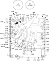
コイン選別装置100は、大まかには本体たるベースボード102、ガイドボード104、コイン口106、コイン位置規制装置108、大径コイン用クレードル110、小径コイン用クレードル112、小径コインリミッタ114、大径コインガイドレール116、小径コインガイドレール118、アンビル122、コイン制動装置124、振分体126及びキャンセル装置128を含んでいる。しかし、小径コインリミッタ114、コイン制動装置124、振分体126及びキャンセル装置128は必須の発明特定事項ではない。
まずベースボード102を図1乃至6を参照して説明する。
ベースボード102は、ガイドボード104と共に薄板状の空間であるコイン通路132を形成し、また、ガイドボード104、大径コイン用クレードル110、アンビル122、振分体126及びキャンセル装置128が取り付けられる機能を有する。したがって、ベースボード102は同様の機能を有する構成全てを含み、本実施例に限られるものではなく、少なくとも本実施例に開示された構成から当業者が推考しうる技術思想の範囲を含むものである。
ベースボード102は、垂立状態に配置された平板状の垂立ボード103と、その両サイドを前方に直角に折り曲げた左サイドボード134及び右サイドボード136によって上下方向に延在する装着凹溝138を構成している。換言すれば、ベースボード102は垂立方向に延在するチャンネル型をしている。ベースボード102は、板金又は樹脂成形によって形成される。
なお、本明細書において、特に言及しない場合、単にベースボード102と言った場合、垂立ボード103を指しているものとする。
First, the
In the present specification, unless specifically mentioned, the
次に、ガイドボード104が主に図1又は図6を参照して説明される。
ガイドボード104は、コイン位置規制装置108、大径コイン用クレードル110、小径コイン用クレードル112、大径コインガイドレール116、小径コインガイドレール118等が取付られる機能を有する。したがって、ガイドボード104は同様の機能を有する構成全てを含み、本実施例に限られるものではなく、少なくとも本実施例に開示された構成から当業者が推考しうる技術思想の範囲を含むものである。
ガイドボード104は平板矩形状であって、ベースボード102に対して回動可能かつ着脱可能に取り付けられる。コイン通路132の清掃、メンテナンス等のためである。
本実施例においては、右サイドボード136の上下方向の中間から左サイドボード134側へ水平に突出する第1軸受142及び第2軸受144にそれぞれ設けられた縦向きU形状の第1軸溝143、第2軸溝145にその上下端部を挿入し、後述の第1スプリング154の中間をベースボード102の孔155を通して裏面に係止させることにより、第1軸溝143、第2軸溝145の底部に押し付けて垂直に保持された第1軸152が設けられている。
第1軸受142と第2軸受144との間の第1軸152に、ガイドボード104の右端部の第3軸受146、第4軸受148が回動可能に取り付けられている。第3軸受146及び第4軸受148は第1軸受142及び第2軸受144間に密に挿入され、ベースボード102に対して上下方向に移動しないように構成されている。
Next, the
The
The
In the present embodiment, the vertical U-shaped
A
この構成によって、ガイドボード104は第1軸152を中心として縦軸回りに回動可能であるが、当該第1軸152に巻き付けられ、一端を後述の磁石保持体376に係止され、他端がガイドボード104に係止された第1スプリング154によってベースボード102側へ近づくように回動され(図3において時計方向)、ガイドボード104がベースボード102に対し平行になった状態でガイドボード104の左端部、換言すれば、左サイドボード134に隣接した位置からベースボード102へ向かって直角に延在するように形成されたL形状の投入口規制片156がベースボード102に当接して静止される。
このガイドボード104の静止位置がコインCが投入される通常位置NPである。
これにより、ベースボード102とガイドボード104とは大径コインLC又は小径コインSCのうち最も厚いコインの厚みよりも僅かに大きい間隔で平行に配置され、上下方向に延在するコイン通路132を形成する。なお、コイン通路132と表現する場合、特に言及しなければ後述の大径コイン通路254、及び、小径コイン通路344をも含んでいる。
With this configuration, the
The stationary position of the
Accordingly, the
次にコイン口106が主に図3及び図6を参照して説明される。
コイン口106は、選別すベきコインCを受け入れる機能を有する。したがって、コイン口106は同様の機能を有する構成全てを含み、本実施例に限られるものではなく、少なくとも本実施例に開示された構成から当業者が推考しうる技術思想の範囲を含むものである。
本実施例におけるコイン口106は、左サイドボード134の近くであって、装着凹溝138の上面に相対する位置において、受け入れるべき大径コインLCの直径よりも僅かに長く、かつ、受け入れるべき大径コインLC又は小径コインSCのうち厚い方の厚みよりも僅かに長いスリット状に形成されている。
コイン口106はベースボード102、ガイドボード104及び投入口規制片156及び固定投入口構成体162によって平面視、横長矩形のスリット状に形成され、縦断面においては大凡下すぼまりの漏斗状に形成される。
具体的には、ガイドボード104の左端部上端部のベースボード102側に突出して上下方向に所定の長さで延在する投入口規制片156とベースボード102、ガイドボード104及び固定投入口構成体162とによって構成されている。
投入口規制片156の反左サイドボード134側の上端部は、上端から下方に向かって左サイドボード134から遠ざかる第1斜面166に形成されている。
Next, the
The
The
Specifically, the left end upper inlet regulating piece extending in projecting
The upper end portion of the insertion
次に固定投入口構成体162を図6及び図8を参照して説明する。
固定投入口構成体162は、第1斜面166と共に投入されるコインを所定の直径以下のコインに制限する機能及びコインが投入される位置を規制する機能を有する。したがって、固定投入口構成体162は同様の機能を有する構成全てを含み、本実施例に限られるものではなく、少なくとも本実施例に開示された構成から当業者が推考しうる技術的思想の範囲を含むものである。
本実施例における固定投入口構成体162は、大凡円筒体であって、円筒部168と平面部172とによって構成され、第1斜面166に相対する部位は円筒部168であるように形成され、ガイドボード104のベースボード102側にあてがってベースボード102に貫通固定されている支軸としての第2軸170に固定されている。
これにより、固定投入口構成体162の円筒部168と第1斜面166との最短の第1距離L1は、受け入れるべき大径コインLCの直径よりも僅かに長く設定されている。
Next, the fixed
The fixed
The fixed
As a result, the shortest first distance L1 between the
次にコイン位置規制装置108を主に図7を参照して説明する。
コイン位置規制装置108は、コイン口106に投入されたコインを所定位置に移動させる機能及び所定直径以上のコインを通過させない機能を有する。したがって、コイン位置規制装置108は同様の機能を有する構成全てを含み本実施例に限られるものではなく、少なくとも本実施例に開示された構成から当業者が推考しうる技術的思想の範囲を含むものである。
本実施例において、コイン位置規制装置108は、コイン規制体174及び第1付勢装置188を含んでいる。
Next, the coin
The coin
In this embodiment, the coin
まずコイン規制体174を説明する。
コイン規制体174は、コイン口106を通過したコインを固定投入口構成体162に密接させ、かつ、受け入れを許容する大径コインLCの直径を超える許容外大径コインのコイン通路132への進行を阻止する機能を有する。
換言すれば、固定投入口構成体162の円筒部168の周面180と第1斜面166との間を通過したコインであっても、受け入れるべきでない大径コインは通過出来ないようにすると共に、コインをその周面が固定投入口構成体162に接した位置において落下させる機能を有する。
更に換言すれば、投入されたコインを固定投入口構成体162の円筒部168の周面180に押し付ける(密接させる)機能を有する。
したがって、コイン規制体174は同様の機能を有する構成全てを含み、本実施例に限られるものではなく、少なくとも本実施例に開示された構成から当業者が推考しうる技術的思想の範囲を含むものである。
本実施例におけるコイン規制体174は、ガイドボード104の表面側の左サイドボード134の近くにおいて水平に固定された支軸としての第3軸176に下端部が回動自在に支持された回動レバ178の先端がベースボード102側に折り曲げられ、水平に延在する棒状体182によって構成されている。
コイン規制体174は、ガイドボード104において、左サイドボード134に近接し、かつ、固定投入口構成体162の水平方向側方に形成された弧状の第1通孔184及びベースボード102に相対して形成した第2通孔186を貫通して第1斜面166の下方であって、かつ、固定投入口構成体162の円筒部168の大凡水平方向側方に配置されている。換言すれば、コイン規制体174は、コイン通路132を横断している。
回動レバ178は、正面視大凡三角形であり、図7において反時計方向へ所定角度回動された場合、第1通孔184及び第2通孔186の端縁187に係止されてそれ以上回動されない大径コイン規制位置MP1に静止されるようになっている。
すなわち、大径コイン規制位置MP1に位置するコイン規制体174と固定投入口構成体162の周面180との第2距離L2は、受け入れるべき大径コインLCの直径よりも僅かに大きく設定され、大径コインLCは後述するようにコイン規制体174を移動させて通過(落下)可能である。換言すれば、直径が第2距離L2を超える大径コインは、固定投入口構成体162とコイン規制体174との間を通過することが出来ない。さらに換言すれば、直径が第2距離L2を超える大径コインは偽貨としてコイン口106から僅かに落下した位置において移動を阻止される。
First, the
The
In other words, even if it is a coin that has passed between the
In other words, it has a function of pressing (in close contact) the inserted coin against the
Accordingly, the
The
The
The
That is, the second distance L2 between the
次ぎにコイン規制体174の第1付勢装置188を説明する。
第1付勢装置188は、コイン規制体174を固定投入口構成体162側に弾性的に近づくように付勢する機能を有する。したがって、第1付勢装置188は同様の機能を有する構成全てを含み、本実施例に限られるものではなく、少なくとも本実施例に開示された構成から当業者が推考しうる技術的思想の範囲を含むものである。
本実施例における第1付勢装置188は、第2スプリング190である。第2スプリング190の一端は回動レバ178の係止孔191に係止され、他端はガイドボード104の正面側に突出する部分、本実施例では後述する係止ピン222に係止されている。
この構成によって、回動レバ178は、図7において時計方向に所定の力で回動するよう付勢される。所定の力とは、大径コインLC又は小径コインSCがそれらの自重によって移動される力であり、結果としてコイン規制体174と固定投入口構成体162との間を通過可能である。
コイン規制体174は、第2スプリング190の付勢力によって、第1通孔184の反左ガイドボード134側の側縁である第1ストッパ192に係止されて静止している。
この静止位置がコイン規制体174の第1待機位置SP1である。
コイン規制体174が第1待機位置SP1に位置する場合、固定投入口構成体162とコイン規制体174との最短距離である第3距離L3は、受け入れるべき小径コインSCの直径よりも僅かに小さい間隔になるように設定される。換言すれば、コイン口106に大径コインLC、又は、小径コインSCの正貨の何れが投入された場合であっても、当該大径コインLC又は小径コインSCの周面がコイン規制体174に接触し、大径コインLC又は小径コインSCの自重によってコイン規制体174を大径コイン規制位置MP1へ向けて押動することにより通過(落下)することができる。
Next, the
The
The
With this configuration, the
The
This stationary position is the first standby position SP1 of the
When the
大径コインLC又は小径コインSCがコイン規制体174を押動する際、それらコインは反力によって固定投入口構成体162側へ押動され、その円筒部168の周面180に密接させられ、その密接した位置から落下する。換言すれば、大径コインLC又は小径コインSCはそれぞれ一定の位置から、真下に位置する大径コイン用クレードル110、又は大径コイン用クレードル110を通過してその真下に位置する小径コイン用クレードル112に落下するので、それぞれ大径コイン用クレードル110又は小径コイン用クレードル112に確実に保持される利点がある。
また、大径コインLC又は小径コインSCは、コイン規制体174と固定投入口構成体162とによって挟まれるので、もし、それらのコインが勢いを付けてコイン口106に投入され、周方向又は面方向に振動している場合であっても、コイン規制体174と固定投入口構成体162とによって挟まれることによってその振動が抑制された後、それぞれ大径コイン用クレードル110又は小径コイン用クレードル112に落下するので確実に保持される利点がある。
さらに、コイン規制体174に対する付勢力は、第1待機位置SP1よりも大径コイン規制位置MP1に近づくにしたがって順次大きくなるようにすることが好ましい。これにより、投入された大径コインLC又は小径コインSCの円滑な落下を確保すると共に固定投入口構成体162へ確実に密接することができる。
なお、第1付勢装置188として、第2スプリング190に代えて錘又は磁石の吸引力若しくは反発力等を利用した付勢装置を採用することができる。
When the large-diameter coin LC or the small-diameter coin SC pushes the
Further, since the large-diameter coin LC or the small-diameter coin SC is sandwiched between the
Further, it is preferable that the urging force with respect to the
As the
次ぎに磁性偽貨保持装置194を説明する。
磁性偽貨保持装置194は、鉄等の磁石によって吸着される材料にて製造した偽コインを吸着してコイン口106の下方の大径コイン用クレードル110に達しないようにする機能を有する、したがって、磁性偽貨保持装置194は同様の機能を有する構成全てを含み、本実施例に限られるものではなく、少なくとも本実施例に開示された技術思想から当業者が推考しうる範囲を含むものである。
本実施例における磁性偽貨保持装置194は、丸棒状の第1永久磁石196からなる。
Next, the magnetic false
The magnetic fake
The magnetic false
第1永久磁石196は、ガイドボード104の正面側のコイン口106の側方に水平に固定されたブラケット198の貫通孔202に当該第1永久磁石196の一端部を挿通して止めネジ200によって固定し、他端部の先端204をガイドボード104に形成した第3通孔206内に臨ませてあるが、ガイドボード104のベースボード102側内面よりは突出していない。換言すれば、第1永久磁石196の先端はコイン口106下方のコイン通路132には突出していない。
第3通孔206は図6に示すように、固定投入口構成体162と第1待機位置SP1に位置するコイン規制体174との最短距離を結ぶ第1直線SL1の側方に面するように形成される、換言すれば、第1永久磁石196の先端204は第1直線SL1の側方に位置する。
この構成により、鉄板等の安価な材料で製造された偽コインが投入された場合、第1永久磁石196の磁力によって当該偽コインは吸着され、それ以上落下できない。すなわち鉄製等の偽コインは第1永久磁石196の磁力によってガイドボード104の内面に圧接された摩擦力が、重力による落下力を上回り、落下できない状態になる。例え当該偽コインをコイン口106に押し込んだ場合であっても、押し込み出来なくなった後は当該磁力によるガイドボード104の内面にとの間の摩擦力によって落下することができない。
The first
As shown in FIG. 6, the third through-
With this configuration, when a false coin made of an inexpensive material such as an iron plate is inserted, the false coin is attracted by the magnetic force of the first
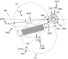
次ぎに大径コイン用クレードル110を主に図7及び図8を参照して説明する。
大径コイン用クレードル110は、コイン口106に投入され、コイン規制体174と固定投入口構成体162との間を落下した大径コインLCを保持すると共に、横方向に案内する機能を有する。したがって、大径コイン用クレードル110は同様の機能を有する構成全てを含み、本実施例に限られるものではなく、少なくとも本実施例に開示された技術思想から当業者が推考しうる範囲を含むものである。
本実施例の大径コイン用クレードル110は、第1係止体207及び第2係止体209を含んでいる。
Next, the large-
The large-
The large-
第1係止体207は、投入された大径コインLCを第2係止体209と共同して保持し、かつ、保持した大径コインLCを横方向へ移動させる機能を有する。
本実施例において、第1係止体207は固定投入口構成体162と共用している。詳述すれば、固定投入口構成体162を構成する円筒部168の周面180が第1係止体207を構成する。第1係止体207と固定投入口構成体162とを共用にすることにより、設置スペースの削減による小型化、及びコスト低減の利点がある。
The
In the present embodiment, the
第2係止体209は、投入された大径コインLCを第1係止体207と共同して保持、かつ、保持した大径コインLCを横方向へ移動させる機能を有する。
第2係止体209は、第2軸170のガイドボード104の表面側において一端を回動自在に支持された第2レバ208の他端部を直角に折り曲げ、ガイドボード104に、第2軸170を中心として形成された弧状の第4通孔210を貫通してコイン通路132を横断し、ベースボード102に形成された第4通孔210に相対して同形状に形成された第5通孔212に突出している棒状の支え体214である。
第2レバ208は第2付勢装置216によって図1及び図8において時計方向に回動されるよう付勢される。
The
The
The
第2付勢装置216は第3スプリング218でありその一端は第2レバ208の側面から横向きに突出する係止ピン222に係止され、他端は回動レバ178の係止孔191に係止されている。本実施例において、第3スプリング218は第2スプリング190と共用、換言すれば、第1付勢装置188と第2付勢装置216とは共用している。したがって、第2スプリング190(第3スプリング218)は、回動レバ178及び第2レバ208に対して図7において時計方向へ回動するよう付勢している。
本実施例において、第3スプリング218による第2レバ208に対する付勢力は、支え体214が第2待機位置SP2に位置する時が最も小さく、順次大きくなるように設定されている。大径コインLCが支え体214と第1係止体207とによって保持された場合、第2レバ208の回動を円滑に行い、大径コインLCの選別を精度良く行うため、及び、第2レバ208の第2待機位置SP2への復帰動を素速く行うためである。第2レバ208の復帰動が素速い場合、大径コインLCに連続して投入された小径コインSCをも精度良く選別することができるからである。
The
In the present embodiment, the urging force of the
第2レバ208は、第3スプリング218の付勢力によって、図7において時計方向のモーメントを付与され、第4通孔210の上端縁である第2ストッパ226に係止されて静止状態に保たれている。この静止位置が大径コイン用クレードル110の第2待機位置SP2である。
なお、第3スプリング218は、第2スプリング190とは独立して設けることができ、スプリングではなく錘又は磁石の吸引力若しくは反発力等を利用した付勢装置によって代替えすることができる。しかし、本実施例のように、コイン規制体174の付勢用の第2スプリング190と第3スプリング218とを共用にすることにより、コイン規制体174に対する付勢力は大径コイン規制位置MP1へ近づくほど大きくなり、投入された大径コインLC又は小径コインSCを固定投入口構成体162へ押し付けることができるので、選別すべきコインの位置を固定投入口構成体162に接触した一定位置にすることができ、コインの落下位置が一定に保たれ、コイン選別の正確性を高めると共に、部品数が減少するのでコストを低減できる効果がある。
The
Note that the
第2レバ208は、第4通孔210及び第5通孔212の範囲内において移動可能である。換言すれば、支え体214は、第2待機位置SP2から、固定投入口構成体162の大凡真下位置、詳しくは、図6に図示するように固定投入口構成体162の外周縁の下方の大径解放位置RP1まで移動可能である。
さらに換言すれば、図8に示すように第2レバ208は支え体214の上端が第2軸170の中心を通る水平線HLのわずか下方位置において第2ストッパ226に係止されて第2待機位置SP2に静止される。この第2待機位置SP2は、図6に示すように支え体214の上端が水平線HLから僅かに下がったコイン規制体174の直ぐ下方位置において設定するのが好ましい。大凡垂直に落下する大径コインLCの直径による選別精度を高めるためである。この状態において、支え体214はコイン規制体174よりも固定投入口構成体162からの直線距離が長く、コイン口106に投入された大径コインLC又は小径コインSCに対してコイン規制体174の影になる位置に設定されることが好ましい。コイン口106に勢いをつけて投入された小径コインSCが、大径コイン用クレードル110によって横方向へ移動されることを防止するためである。
The
In other words, as shown in FIG. 8, the
次ぎに、第1係止体207たる固定投入口構成体162を主に図6及び図8を参照して説明する。
固定投入口構成体162は、スリット形のコイン口106の短辺の一方を画定すると共に、支え体214と共に大径コイン用クレードル110を構成する機能を有する。
本実施例において、固定投入口構成体162は全体として円柱状の周面180を有し、一部に平面部172を形成した軸線に対し直交方向の断面がD形状を有する。
具体的には、金属製の円筒体234の一部を切削して平面部172を形成し、当該平面部172が支え体214側に向かって斜め下向きに配置されている。
第2待機位置SP2に位置する支え体214と円筒体234の周面180とは第4距離L4の長さ離れている。
この第4距離L4は、受け入れるべき大径コインLCの直径よりも僅かに小さい。換言すれば、第4距離L4は10円コインの直径よりも僅かに小さい。
したがって、受け入れるべき大径コインLCは支え体214と固定投入口構成体162の円弧状の周面180間を通過することができない。換言すれば、真正の大径コインLCは大径コイン用クレードル110の第1係止体207と第2係止体209によって保持された後、横方向へ移動されて選別される。
すなわち、選別されるべき大径コインLCは周面180と支え体214との間に支えられて保持され、第2レバ208には支え体214に作用する大径コインLCの重量によって、図8において反時計回り方向のモーメントが作用する。
このモーメントは、大径コインLCが正貨である場合、第3スプリング218(第2スプリング190)による時計回りのモーメントよりも大きく設定されるので、真正の大径コインLCは第2レバ208の回動と共に固定投入口構成体162回りを反時計方向へ円弧状に移動される。
第2レバ208が第2待機位置SP2から大凡45度回動して大径解放位置RP1に近づいた場合、大径コインLCの周面が相対する固定投入口構成体162の周面は、平面部172になり、支え体214と平面部172との間の直線距離は第5距離L5となり、大径コインLCの直径よりも大きくなる。
第5距離L5は大径コインLCの直径よりも大きいので、大径コインLCは自己重量による転動力によって第2レバ208の回動方向へ向かって支え体214上から転げ落ちる。換言すれば、真正の大径コインLCは大径コイン用クレードル110によって横方向へ移動(転動)される。
Next, the fixed charging
The fixed
In the present embodiment, it has a cylindrical
Specifically, by cutting a portion of the
The
This fourth distance L4 is slightly smaller than the diameter of the large coin LC to be received. In other words, the fourth distance L4 is slightly smaller than the diameter of the 10 yen coin.
Accordingly, the large-diameter coin LC to be received cannot pass between the
That is, the large-diameter coin LC to be sorted is supported and held between the
This moment is set larger than the clockwise moment by the third spring 218 (second spring 190) when the large coin LC is a true coin. Along with the rotation, the fixed
When the
Since the fifth distance L5 is larger than the diameter of the large-sized coin LC, the large-sized coin LC rolls down on the
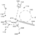
次ぎに大径コインLCのための大径コインガイドレール116を主に図5、6及び図10を参照して説明する。
大径コインガイドレール116は、大径コイン用クレードル110から転がり落ちた大径コインLCを下流へ案内する機能を有する。
したがって、大径コインガイドレール116は同様の機能を有する構成全てを含み、本実施例に限られるものではなく、少なくとも本実施例に開示された技術思想から当業者が推考しうる範囲を含むものである。
本実施例において、大径コインガイドレール116は、ベースボード102に形成された五角形状の大径コインLC用の透孔238の直線状の透孔下縁242に沿って配置されている。
本実施例において、大径コインガイドレール116は、ガイドボード104の裏面からベースボード102へ向かって所定量横向きに突出する第1大径ガイドレール244及びベースボード102側に形成された第2大径ガイドレール246により構成されている。しかし、第2大径ガイドレール246は必要に応じて設ければよい。換言すれば、第1大径ガイドレール244のみで大径コインガイドレール116を構成することが出来る。
また、ベースボード102のガイドボード104側の透孔238の下側の側面には保護プレート232を貼付することが好ましい。
Next, the large-diameter
The large-diameter
Accordingly, the large-diameter
In the present embodiment, the large-diameter
In the present embodiment, the large-diameter
Further, it is preferable to attach a
まず第1大径ガイドレール244が説明される。
第1大径ガイドレール244はガイドボード104の下端部からベースボード102側へ透孔238の透孔下縁242に沿って所定巾で細長板状に突出し、ベースボード102側へ向かって前下がりに傾斜すると共にコインの進行方向に対しても前下がりに傾斜している。換言すれば、第1大径ガイドレール244は大径コインLCの転動方向に対し前下がりであって、かつ、ベースボード102に近づくほど下降するように傾斜している。
以下、大径コインLCの転動方向の傾斜を「長手方向傾斜」、ベースボード102側への傾斜を「短手方向傾斜」という。
具体的には、第1大径ガイドレール244は柱状であって、かつ、図10に示すように断面形状が台形状であって、ガイドボート104と一体に形成され又は別体に形成されて一体化されている。
具体的には、第1大径ガイドレール244は、長手方向傾斜が約20度の角度で傾斜している。換言すれば、第1大径ガイドレール244は大径コイン用クレードル110から遠ざかるにしたがって一定比率で前下がりになるように形成されている。
一方、短手方向傾斜は約30度の角度で傾斜している。換言すれば、第1大径ガイドレール244はベースボード102に近づくにしたがって一定比率で前下がりになるよう傾斜している。
First, the first large-
The first large-
Hereinafter, the inclination in the rolling direction of the large coin LC is referred to as “longitudinal inclination”, and the inclination toward the
Specifically, the first large-
Specifically, the first large-
On the other hand, the lateral direction inclination is inclined at an angle of about 30 degrees. In other words, the first large-
この構成により、第1大径ガイドレール244上を転動する大径コインLCは、長手方向傾斜によって第1大径ガイドレール244上を大径コイン用クレードル110から遠ざかる方向に転動しつつ、短手方向傾斜によって(コイン面に対する)横方向へ移動しつつ転動するので、ついには大径コインLCは第1大径ガイドレール244上から落下する。
第1大径ガイドレール244は、所定の幅、好ましくは、大径コインLCの厚みの約2倍の幅、換言すれば、コイン通路132の幅と一致して形成されることが好ましい。しかし、第1大径ガイドレール244の先端は透孔238内に突出させることができるが、後述の大径コインLCの垂立通路294の厚みを増加させねばならないので、透孔238内に突出させない方が好ましい。
With this configuration, the large-diameter coin LC that rolls on the first large-
The first large-
次に第2ガイドレール246を説明する。
第2大径ガイドレール246は、大凡ベースボード102の透孔238を構成する透孔下縁242の構成部分によって構成されている。本実施例においては、ベースボード102の裏側において固定された金属製の保護プレート245によっても構成されているが、保護プレート245は必要に応じて設けられるので、必須の構成ではない。
ベースボード102の透孔下縁242の上端は、ベースボード102の裏側へ向かって前下がりに傾斜する直線状の斜面248に形成されている。以下、この傾斜も短手方向傾斜といい、傾斜角度は約60度である。
Next, the
The second large-
The upper end of the through hole
保護プレート232の上端も斜面248に連続する斜面に形成されている。
保護プレート232は、図5に示すように倒立台形であって、ベースボード102の表面側に接着等により固定され、その上端縁は透孔下縁242に重なっている。
The upper end of the
The
斜面248は、平面視で大径コインLCの大凡一枚分の厚みである。
第2大径ガイドレール246は、第1大径ガイドレール244の直ぐ下方にその上端が配置されているので、第1大径ガイドレール244と第2大径ガイドレール246とは、平面視、一枚板状に見える。
詳細には、第2大径ガイドレール246の延長線ELは、第1大径ガイドレール244に交差するように配置されている。
換言すれば、第1大径ガイドレール244の短手方向下端に対し第2大径ガイドレール246の短手方向上端とが段差をなした階段状に形成されている。
そして、第1大径ガイドレール244の短手方向の下端と垂立面250とは滑らかな曲線によって接続されている。大径コインLCが第1大径ガイドレール244から落下する際、大径コインLCの面が円滑に案内されてスムーズに落下できるようにするためである。
The slope 2 4 8 has a thickness of approximately one large coin LC in plan view.
Since the upper end of the second large-
Specifically, the extension line EL of the second large
In other words, the upper end in the short direction of the second large-
The lower end in the short direction of the first large-
次ぎに透孔238を主に図5を参照して説明する。
透孔238は、選別された真正の大径コインLCが大径コイン出口252へ案内される大径コイン通路254の入口256としての機能を有する。換言すれば、透孔238は、下方の大径コイン通路254に落下するための落下口258である。
さらに、透孔238は、大径コインLCを確実に落下させるため、大径コインLCの直径部全体が透孔238に相対しない状態では透孔238に落下しないように後述の案内体270と協働して大径コインLCの落下を制御する機能を有している。
Next, the through
The through
Further, the through-
透孔238は、全体として台形状であり、詳細にはその透孔下縁242は直線状であり、大径コインLCの直径に対し約二倍の長さを有し、大径コイン用クレードル110側から大径コインLCの転動方向下流に向かって前下がりに形成されている。換言すれば、透孔下縁242は、第1大径ガイドレール244の僅か下方において当該第1大径ガイドレール244と平行に斜めに形成されている。
透孔上縁262は、全体として波形に形成され、大径コインLCが転動するコイン通路132の上流側から下流側に向かって、最小の第1高さH1から小さな増加率で拡大する小増加部264、その小増加部264に続いて、小増加部264よりも大きな増加率で拡大する大増加部266が形成されて最大高さに形成され、次いで順次小減少率で第3高さH3になるまで低くなる減少部268とによって形成されている。
第3高さH3部は、透孔下縁242に対し直角に上方に延在する下流縁272の高さである。
第1高さH1は上流縁274の高さであり、大径コインLCの半径よりも僅かに小さく、第2高さH2は大径コインLCの直径とほぼ同一の高さであり、第3高さH3は大径コインLCの半径よりも僅かに大きく設定されている。
The through-
The
The third height H3 is the height of the
The first height H1 is the height of the
次ぎに案内体270を説明する。
案内体270は、後述の大径コイン通路体286の垂立部282から横向きにベースボード102側に向かって突出する板状の突起であり、小増加部264に相対した位置において透孔238に突出し、案内体270の案内端面278は、平坦であって、かつ、ベースボード102のコイン通路132を構成する壁面と同一の平面内に配置される。換言すれば、案内端面278は大径コインLCのコイン通路132を構成している。
Next, the
The
案内体270と透孔上縁262とで落下規制装置278を構成している。
落下規制装置278は、大径コインLCが後述する大径コイン通路254に円滑に落下するように規制する機能を有する。
本実施例においては、特に透孔上縁262が前述のように形成されているため、大径コインLCは当該第1大径ガイドレール244のベースボード102側への短手方向への傾斜によって、ベースボード102に大径コインLCの面部が案内されつつ転動するが、小増加部264に相対している間、転動する大径コインLCは、その中心の下側は案内体270の案内端面278によって案内され、かつ、中心よりも上方の面は小増加部266に相対するベースボード102に面接触し、さらに、その下端部後ろ側部は同様にベースボード102によって案内されるので、透孔238内に進入することができない。
大径コインLCが透孔上縁262の大増加部266に相対した場合、案内端面278は存在せず、かつ、大径コインLCの中心よりも上側の面とベースボード102との接触部が徐々に減少すると共に大径コインLCの転動方向の全体が透孔238に相対するので、大径コインLCは第1大径ガイドレール244のベースボード102側への短手方向傾斜によって、ベースボード102の裏面方向へ滑り落ちることが可能になり、その下端部が透孔238内へ進行する。
次いで大径コインLCの下端は第2大径ガイドレール246上へ移った後、その第2大径ガイドレール246の傾斜によって、その上からも落下する。状況によっては、大径コインLCは第2大径ガイドレール246上に落下せずに大径コイン通路254へ落下することもある。
これにより、大径コインLCは透孔238内へ落下し、ベースボード102の裏面側の大径コイン通路254へ案内される。
The
The
In the present embodiment, in particular, since the
When the large coin LC faces the
Next, after the lower end of the large-diameter coin LC moves onto the second large-
As a result, the large-diameter coin LC falls into the through
次ぎに逸らせ体275を主に図5及び図9を参照して説明する。
逸らせ体275は、大径コインLCが大径コインガイドレール116上を転動している最中に透孔238に落下しない場合、強制的に透孔238内に進行(落下)するよう案内する機能を有する。
したがって、逸らせ体275は同様の機能を有する構成全てを含み、本実施例に限られるものではなく、少なくとも本実施例に開示された技術思想から当業者が推考しうる範囲を含むものである。
本実施例において、逸らせ体275は、下流縁272からガイドボード104側、かつ、コイン転動の上流側に向かって斜めに延在している小さな矩形板276である。
矩形板276はベースボード102と一体又は別体に、樹脂又は板金成型され、接着、スクリュウ等によってベースボード102に一体化され、その先端は、ガイドボード104に形成された開口277に突入されている。
大径コインLCが仮に透孔238に落下しなかった場合、大径コインLCの前側周面が逸らせ体275に衝突する。
これにより、大径コインLCの先端は逸らせ体275のベースボード102へ近づく方向の傾斜によって、ベースボード102側へ強制的に移動されるので、大径コインLCの下端部は透孔238内へ進行し、その後落下する。
Next the deflecting member 27 5 will be explained mainly with reference to FIGS. 5 and 9.
Deflecting member 27 5, when the large-diameter coin LC is not dropped into the through
Therefore, the deflecting member 27 5 includes all components having the same function is not limited to this example, is intended to include a range in which those skilled in the art from the technical ideas disclosed in at least this embodiment may be inferred.
In this embodiment, the deflecting member 27 5, guide
The
If large-diameter coin LC is not temporarily dropped into the through
Thus, by the inclination of the direction approaching the
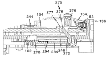
次に大径コイン通路254を主に図2及び図11を参照して説明する。
大径コイン通路254は、大径コイン用クレードル110によって選別された後、透孔238に落下した大径コインLCを所定位置に案内する機能を有する。
したがって、大径コイン通路254は同様の機能を有する構成の全てを含み、本実施例に限られるものではなく、少なくとも本実施例に開示された構成から当業者が推考しうる技術的思想の範囲を含むものである。
本実施例において、大径コイン通路254はベースボード102の背面側に形成される。
具体的には、大径コイン通路254は、ベースボード102の背面側に板状の垂立部282と板状の水平部284とにより倒立T字形状をしている板状の大径コイン通路体286を固定することにより形成されている。
垂立部282の左右側縁には大径コインLCの厚みの約2倍の突出量の左側壁288及び右側壁292が形成されているが上端は開口されている。
垂立部282、左側壁288及び右側壁292によって上下方向に延在する垂立通路294が形成される。
右側壁292は透孔238の下流縁272に相対して形成されている。換言すれば、大径コインガイドレール116上を転動する大径コインLCの進行方向に対し直角をなすよう形成されている。
左側壁288は上流縁に相対して配置され、下方に行くにしたがって順次右側壁292に近づくよう形成され、最下端部は大径コインLCの直径よりも僅かに大きくして、大径コインLCの大径コイン出口252を構成している。
水平部284の幅は、ベースボード102の幅よりも僅かに狭く形成され、その水平部下端はベースボード102の下端と一致する位置に設定されている。水平部284の左右端部からそれぞれベースボード102側に向かって第2左側壁298、第2右側壁302が突出形成され、大径コイン出口252の下方に連なる板状の空間304を画定形成する。
空間304の下端面は解放され、大径コイン落下口306が形成される。
したがって、大径コイン落下口306はコイン選別装置100のベースボード102の裏面側下端面のほぼ全面に構成される。
この構成により、透孔238から落下した大径コインLCは左側壁288と右側壁292とにより案内されて垂立通路294を落下し、大径コイン出口252、そして空間304を通過して最終的に大径コイン落下口306から落下する。
Next, the large-
The large-
Therefore, the large-
In this embodiment, the large-
Specifically, the large-
A
A
The
The
The width of the
The lower end surface of the
Therefore, the large-diameter
With this configuration, the large-diameter coin LC that has fallen from the through
次に小径コイン用クレードル112を主に図1及び図6を参照して説明する。
小径コイン用クレードル112は、小径コインSCの直径及び重量によって正貨と偽貨に選別する機能を有する。
したがって、小径コイン用クレードル112は同様の機能を有する構成の全てを含み、本実施例に限られるものではなく、少なくとも本実施例に開示された技術思想から当業者が推考しうる範囲を含むものである。
本実施例においては、小径コイン用クレードル112は、従来公知のクレードルを用いることにより、小径コインSC(100円コイン)の直径及び重量を機械的手段により判別し、正貨と偽貨とに選別する機能を有する。
具体的には、大径コイン用クレードル110を構成する第1係止体207たる固定投入口構成体162と第2係止体209たる第2レバ208の支え体214との間を通過した小径コインSCが、小径コイン用クレードル112に保持された場合、小径コイン用クレードル112がその重量によって横方向へ転動され、小径コインSCを後述の小径コインガイドレール118へ案内する。
Next, the small-
The small-
Therefore, the small-
In this embodiment, the small-
Specifically, the small diameter that has passed between the fixed
小径コイン用クレードル112は、大径コイン用クレードル110の直下のコイン通路132に配置されている。
小径コイン用クレードル112は、小径コインクレードル本体312、一対の第3係止体316及び第4係止体318及び小径付勢体320を含んでいる。
小径コインクレードル本体312は、板金製であり、ガイドボード104の表面側に横向き水平に突出固定された支軸としての第3軸314に回転自在に支持され、ガイドボード104と平行な垂立平面内において回転可能である。
第3係止体316及び第4係止体318は、小径コインクレードル本体312から第3軸を挟んで反対方向に延在する一対の棒体の先端部をベースボード102側に折り曲げて形成され、大径コイン用クレードル110の直ぐ下方に、所定の第6距離L6で配置された第1爪324及び第2爪326によって構成されている。
第6距離L6は、真正の小径コインSCが第1爪324及び第2爪326によって保持された後、小径コイン用クレードル112が回動され、図6において当該小径コインSCの軸心が第2爪326よりも右方へ移動し、自重によって転動可能になった場合、自身の転動力によって当該第2爪326上から転げ落ちることが可能に設定される。この小径コイン用クレードル112の回動位置が小径解放位置RP2である。
第3係止体316(第1爪324)は、第3軸314の上方において当該第3軸314を中心にガイドボード104に弧状に形成された第6通孔328を通ってコイン通路132に突出している。
第4係止体318(第2爪326)は、第3係止体316と同様にガイドボード104に弧状に形成された第7通孔332を通ってコイン通路132に突出している。
これにより、大径コイン用クレードル110に係止されずに落下した真正の小径コインSCは、第3係止体316(第1爪324)と第4係止体318(第2爪326)とによって保持(載置)される。
小径付勢体320は、本実施例では錘322である。
The small-
The small-
The small-diameter coin cradle
The
At the sixth distance L6, after the genuine small-diameter coin SC is held by the
The third locking body 316 (first claw 324) is passed through the
Similar to the
As a result, the genuine small-diameter coin SC that has fallen without being locked to the large-
The small-diameter biasing body 320 is a weight 322 in this embodiment.
小径コイン用クレードル112は、小径コインSCが載置されない状態において、錘322によって図1において反時計方向(図6においても反時計方向)のモーメントを受け、反時計回りに回動されると共に、第4係止体318(第2爪326)が第7通孔332の上端縁たる第3ストッパ334に係止され、第3待機位置SP3に静止される。
小径コイン用クレードル112に所定直径及び所定重量の真正の小径コインSCが保持された場合、当該小径コインSCの重量によって小径コイン用クレードル112は図1において時計方向に転動され、小径コインSCの重心が第4係止体318の外方(図6において右方)へ移動した場合、当該小径コインSCは自重による転動力によって転がって、第4係止体318から斜め右下方へ落下する。
小径コインSCが小径コイン用クレードル112から落下した場合、錘322によるモーメントによって、小径コイン用クレードル112は第3待機位置SP3に戻される。
The
When the small-
When the small-diameter coin SC falls from the small-
次に小径コインリミッタ114を主に図1及び図6を参照して説明する。
小径コインリミッタ114は、小径コイン用クレードル112によって横方向に転向された小径コインSCが受け入れることが出来ない直径であることを判別する機能を有する。
換言すれば、受け入れるべき正貨の大径コインLCよりも小径であるが、受け入れるべき正貨の小径コインSCよりは大径の受け入れるべきでない偽小径コインを排除する機能を有する。
したがって、小径コインリミッタ114は同様の機能を有する構成の全てを含み、本実施例に限られるものではなく、少なくとも本実施例に開示された技術思想から当業者が推考しうる範囲を含むものである。
本実施例において、小径コインリミッタ114は、ガイドボード104の表面側から横向きに突出する第4軸336に回動自在に支持されたL形の規制レバ338である。規制レバ338の先端はベースボード102側へ横向きに折り曲げられ、大凡水平に配置された棒状の規制体342を有し、ガイドボード104の第8通孔346及びベースボード102の透孔238の小増加部264に対応する部分を貫通し、小径コイン用クレードル112の直ぐ下流の小径コイン通路344を横断している。
本実施例において、小径コイン用クレードル112の直ぐ下流とは、図6に示すように、小径コイン用クレードル112の第3待機位置SP3における第4係止体318に対して直上の僅かに下流側に配置されている。
規制レバ338は、自重によって図1において反時計方向の自己モーメントを有し、規制体342が第8通孔346の端縁348に係止された状態で静止される。この規制レバ338の静止位置が第4待機位置SP4である。
Next, the small
The small-
In other words, it has a function of eliminating false small-diameter coins that are smaller in diameter than the large-sized coin LC that is to be accepted but larger in diameter than the small-sized coin SC that is to be accepted.
Accordingly, the small-
In this embodiment, the small-
In this embodiment, the immediate downstream of the small-
The regulating
第4待機位置SP4に位置する規制体342は、小径コイン用クレードル112が保持した小径コインSCの重量によって転動した場合、小径コインSCの小径解放位置RP2における第4係止体318との第7距離L7が、真正の小径コインSCの直径よりも僅かに大きい間隔に設定されている。
規制体342は、第8通孔346内において移動できる。
この構成によって、小径コイン用クレードル112に支持された小径コインSCであっても、真正の小径コインSCよりも僅かに大径の偽小径コインは規制体342と第4係止体318との間を通過することができず、その位置において滞留する。
When the restricting
The restricting
With this configuration, even for the small-diameter coin SC supported by the small-
次に小径コインガイドレール118を主に図1及び図6を参照して説明する。
小径コインガイドレール118は、小径コイン用クレードル112によって横方向に転向(移動)された小径コインSCを所定方向へ案内する機能を有する。
したがって、小径コインガイドレール118は同様の機能を有する構成の全てを含み、本実施例に限られるものではなく、少なくとも本実施例に開示された技術思想から当業者が推考しうる範囲を含むものである。
本実施例において小径コインガイドレール118は、図6に示すように小径コイン用クレードル112の横方向の斜め下方に位置調整自在に配置された、所定の長さ、すなわち、大凡小径コインSCの直径よりも僅かに短かく構成された矩形の案内体352である。
案内体352は、その表側に突出するスライダ350がガイドボード104の下端部に形成された小径コイン用クレードル112から離れるにしたがって斜め下方向に前下がりに傾斜する直状の長孔である第9通孔354内においてスライド可能に挿入され、所定位置でガイドボード104にスクリュウ356により固定される。
案内体352は、ベースボード102の左サイドボード134と右サイドボード136の中間に配置され、その下流側にはその下流端と右サイドボード136との間に小径コインSCの直径以上の距離、好ましくは小径コインSCの直径の約1.5倍の距離が存する小径コイン落下口358が形成されている。
案内体352は、ポリアセタール等の耐摩耗性を有する樹脂で成形されているが、金属であってもよい。
案内体352の上面357は、小径コインSCの厚みとほぼ同一の幅を有し、小径コインSCの転動方向に対して前下がりの直線状斜面を呈している。
小径コイン用クレードル112から落下した小径コインSCは案内体352の上面357に落下し、その上を転動した後、小径コイン落下口358に落下する。
Next, the small-diameter
The small-diameter
Therefore, the small-diameter
In this embodiment, the small-diameter
The
The
The
The
Diameter coin SC dropped from the small
次にアンビル122が図6を参照して説明される。
アンビル122は、案内体352によって案内された小径コインSCを跳ね返らせて所定方向へ案内する機能を有する。
したがって、アンビル122は同様の機能を有する構成の全てを含み、本実施例に限られるものではなく、少なくとも本実施例に開示された技術思想から当業者が推考しうる範囲を含むものである。
本実施例においてアンビル122は、スクリュウ359によってベースボード102の下端部の右サイドボード136に隣接した位置に固定されている。
アンビル122は、横向き五角形の山形形状であり、小径コインガイドレール118に面する、換言すれば小径コイン落下口328の下方に位置する上向きの第3斜面360を有する。案内体352から落下した小径コインSCは、第3斜面360に所定の速度で衝突し、上向きの反対方向、換言すれば、小径コインガイドレール118の下側に向かって跳ね返る。
小径コインSCの正貨たる100円コインがアンビル122に衝突し、跳ね返った場合、当該100円コインは、左サイドボード134側へ向かって所定量跳ね返り、小径コインSCの正貨通路362に達し、その下端の小径コイン小径コイン正貨口364から落下する。正貨でない場合、アンビル122に近い偽貨通路368に達し、その下端の小径コイン偽貨口372から落下する。
Next, the
The
Therefore, the
In this embodiment, the
The
When a 100-yen coin, which is a small coin of the small coin SC, collides with the
次にコイン制動装置124を主に図1及び図6を参照して説明する。
コイン制動装置124は、小径ガイドレール118によって案内された後の小径コインSCの速度を減速する機能を有する。
したがって、コイン制動装置124は同様の機能を有する構成の全てを含み、本実施例に限られるものではなく、少なくとも本実施例に開示された技術思想から当業者が推考しうる範囲を含むものである。
本実施例において、コイン制動装置124は従来公知の永久磁石374によって構成されている。
すなわち、コイン通路132の側方に第2永久磁石374を配置することにより、着磁性を有するコインCを引き寄せ、コイン通路132を構成するガイドボード104との摺動抵抗を増加させることにより、当該コインCの移動(転動)速度を減速するものである。
コイン制動装置124は、磁石保持体376及び永久磁石374を含んでいる。
磁石保持体376は、大凡矩形の板状であり、図3において明らかなように、ガイドボード104の外側に並列配置され、その右端部の第5軸受378、第6軸受382に第1軸152を貫通させて縦軸回りに回動自在に支持され、第1スプリング154の一端を係止することによって、ガイドボード104に近づくように回転力が付与されている。
Next, the
Accordingly, the
In this embodiment, the
That is, by arranging the second
The
磁石保持体376の中間の下端部にベースボード102側に突出する矩形箱形の磁石保持部380が形成され、当該磁石保持部380の内底部に第2永久磁石374が固定されている。
磁石保持部380の小径コイン通路344側は、垂立平面状に形成された平坦部384に形成され、小径コインSCの転動方向において小径コインガイドレール118とほぼ同程度の長さを有し、案内体352と平行に配置され、そのコイン転動方向の上流側端部は、案内体352の中央部に相対し、下流側端部は案内体352よりも下流に位置し、下端縁は案内体352の上面359の直上に配置されている。
A rectangular box-shaped
The small-
磁石保持部380に相対するガイドボード104には第10通孔386が開口され、磁石保持部380が挿入されて、永久磁石374の磁力線がコイン通路132に効率的に作用するようにしてある。
平坦部384は、通常、小径コイン通路344に対し平行をなすよう位置調整装置388によって調整される。
A tenth through
次に位置調整装置388を主に図1及び図3を参照して説明する。
位置調整装置388は、磁石保持体376の表面先端部から上方へ向かって延長された第1ステー392、調整ネジ394及びベースボード102の上端部中央に配置した突き当て部396により構成されている。
第1ステー392の上端部にはネジ孔393が形成され、棒状の調整ネジ394がねじ込まれ、ガイドボード104に一体に構成された突き当て部396側へ向かって進退可能にねじ込まれている。
突き当て部396は、ベースボード102が樹脂により成型される場合、金属製円柱状の受け床398が埋め込まれ、調整ネジ394の先端が受け床398の平端面に当接するように構成される。
この構成により、調整ネジ394の先端が受け床398の平端面に突き当てられることにより、第1軸152を支点に第1スプリング154によってベースボード102に近づくよう付勢されている磁石保持体376の回動を停止させ、ベースボード102との間隔を調整することにより、換言すれば小径コイン通路344を転動する小径コインSCとの距離を調整することにより、真正な小径コインSCに適当な制動力を付与し、アンビル122による跳ね返り量を調整し、正貨通路362へ到達するように調整する。
Next, the
The
A
When the
With this configuration, by being abutted against the flat end surface of the receiving tip of the adjusting
次ぎにリジェクト装置402が主に図2及び図3を参照して説明される。
リジェクト装置402は、投入されたコインがコイン通路132又は小径コイン通路344において(ジャムした)滞留した場合、具体的には、磁性偽貨保持装置194の第1永久磁石196に偽貨が吸着された場合、大径コイン用クレードル110に保持され続けた場合、小径コイン用クレードル112に保持された偽貨が所定の重量を有さないため小径コイン用クレードル112が転動しない場合、若しくは小径コインリミッタ114に偽小径コインが転動を阻止された場合、それら滞留コインを落下させる機能を有する。
したがって、リジェクト装置402は同様の機能を有する構成の全てを含み、本実施例に限られるものではなく、少なくとも本実施例に開示された技術的思想から当業者が推考しうる範囲を含むものである。
本実施例において、リジェクト装置402は第1リジェクトピン404及び第2リジェクトピン406を含んでいる。
Next, the
When the inserted coin stays (jammed) in the
Accordingly, the
In this embodiment, the
第1リジェクトピン404及び第2リジェクトピン406は、前記滞留コインを落下させるため、ガイドボート104がベースボード102から離れるように移動された場合、当該滞留コインをコイン通路132に留め置く機能、換言すれば、滞留コインが磁性偽貨保持装置194、大径コイン用クレードル110、小径コイン用クレードル112又は小径コインリミッタ114と共に移動することを防止する機能を有する。
第1リジェクトピン404は、第1ステー392と一体に大凡対称に形成した第2ステー408の先端をベースボード102側に向けて屈曲させた直状の棒体によって構成されている。
第2リジェクトピン406は、磁石保持体376の先端から下方に延在する第3ステー412の先端をベースボード102側に向けて屈曲させた直状の棒体によって構成されている。
第1リジェクトピン404の先端は、図7に示すようにコイン口106の直下の第1永久磁石196の側方であって、かつ、第2レバ208の直上に相対して形成された第11通孔414を通ってコイン通路132の側方に配置されている。
第2リジェクトピン406の先端はガイドボード104に形成された長孔形状の第12通孔416を貫通し、図6に示すように第3待機位置SP3における第1爪324と第2爪326との上端を直線で結んだ第2直線の僅か上方におけるコイン通路132の側方に静止される。
したがって、第1リジェクトピン404及び第2リジェクトピン406の先端は、コイン通路132には突出しないので、投入されたコインと係合することはない。
この構成によって、ガイドボード104が回動された場合、当該ガイドボード104の所定の回動範囲内ではガイドボード104のみが回動し、磁石保持体376は静止状態に保持される。結果として、相対的に第1リジェクトピン404がコイン口106の直下のコイン通路132側に突出し、及び第2リジェクトピン406が相対的に小径コイン用クレードル112におけるコイン通路132側に突出する。
これにより、例えば固定投入口構成体162とコイン規制体174との間に挟まれて静止している偽の大径コインは、相対的に第1リジェクトピン404によって、その面をベースボード102側に押されて固定投入口構成体162とコイン規制体174上から外される結果、自重によって落下し、後述のキャンセル通路428に落下して後、顧客に対する返却口へ戻される。
一方、第1爪316と第2爪326との間に保持された、又は、小径コインリミッタ114によって移動を阻止された偽の小径コインは第2リジェクトピン406によって押し出され、それらの間から外されて落下させられ、前述同様にキャンセル通路428に落下して後、返却口へ戻される。
The
The
The
The tip of the
The tip of the
Therefore, the tips of the
With this configuration, when the
As a result, for example, a fake large-diameter coin that is held stationary between the fixed
On the other hand, the fake small-diameter coin held between the
次に振分体126を主に図6を参照して説明する。
振分体126は、アンビル122によって跳ね返った小径コインSCを小径コイン正貨口364又は小径コイン偽貨口372に案内する機能を有する。
振分体126はL形棒状であってベースボード102の下端部背面中央において水平方向に延在する第13通孔418を貫通した状態において、図示しないスクリュウをベースボード102にねじ込むことにより位置調整可能に固定されている。
スクリュウを緩めることにより、第13通孔418の範囲において、振分体258を図6において右又は左方向に位置調整可能である。
図6において、振分体126の左側が小径コイン正貨口364であり、右側が小径コイン偽貨口372である。
したがって、通常、小径コインSCが100円コインである場合、アンビル122の第3斜面360によって跳ね返った100コインは、振分体126の左側に達する。達しない場合であっても、100円コインの重心よりも右側下のコイン周面が振分体126に当たった場合、小径コイン正貨口364へ案内される。小径コイン正貨口364から落下した100円コインは図示しない金庫へ案内されて保留される。偽貨である場合、跳ね返り量が小さく、振分体126の右側の小径コイン偽貨口372に落下する。
小径コイン偽貨口372から落下した偽の小径コインは、後述のキャンセル通路428を経由して返却口(図示せず)へ戻される。
Next, the
The
In the
By loosening the screw, the
In FIG. 6, the left side of the sorting
Therefore, normally, when the small-diameter coin SC is a 100-yen coin, the 100 coins bounced off by the
The false small-diameter coin that has dropped from the small-diameter coin
次にキャンセル装置128を主に図2又は図3を参照して説明する。
キャンセル装置128は、リジェクト装置402を作動させる機能、還元すれば、コイン通路132においてジャムしたコインをキャンセル通路428へ落下させる機能を有する。
キャンセル装置128は、キャンセルレバ422、押動棒424、ガイドボード104に形成されたカム面426及び戻しスプリング430を含んでいる。
まずキャンセルレバ422を説明する。
キャンセルレバ422は、ベースボード102の背面に固定した支軸としての第5軸432に回動自在に取り付けられると共に戻しスプリング430によって図2において時計方向へ回動力を付与され、通常、水平状態(ベースボード102の上縁に一致した位置)において図示しないストッパによって静止される。
Next, the canceling
The cancel
The cancel
First, the cancel
Cancel
次に押動棒424を説明する。
押動棒424は、キャンセルレバ422の先端部側面からベースボード102の第14通孔434を貫通してガイドボード104側へ突出する棒体である。押動棒424の先端は半球形に形成され、ガイドボード104の静止位置におけるカム面426に近接配置される。
押動棒424の貫通位置は、コイン通路132を外れており、コインの進行(転動)に対し何ら悪影響を及ぼさない。
Next, the
Pushing
The penetrating position of the
次にカム面426を説明する。
カム面426はガイドボード104の背面に形成され、第5軸432を中心とし、かつ押動棒424に相対する位置において所定の幅(円弧運動を行う押動棒424が回動しても接触を継続し得る幅)を持った垂立溝状に形成され、下側ほどベースボード102に近づく斜面に形成されている。
換言すれば、キャンセルレバ422を下方に押し下げた場合(図2おいて反時計方向に回動させた場合)、キャンセルレバ422から突出する押動棒424がガイドボード104の裏面に形成したカム面426を押すので、ガイドボード104は第1軸152を支点にベースボード102から離れるように回動される。
この回動範囲においてガイドボード104は、磁石保持体376には当接しないように設定されている。
この回動によって、第1リジェクトピン404及び第2リジェクトピン406は、相対的に滞留したコインを前述のように押し出してリジェクトすることができる。
Next, the
The
In other words, when the cancel
In this rotation range, the
By this rotation, the
次にキャンセル通路428を主に図11を参照して説明する。
キャンセル通路428は、キャンセルレバ422の操作によってコイン通路132から落下させられた偽の大径コイン、偽の小径コイン又はコイン通路132に詰まった(ジャムした)正貨の大径コインLC若しくは小径コインSCを小径コイン偽貨口372に並置されたキャンセル落下口436へ案内する機能を有する。
キャンセル通路428は、ガイドボード104の下方においてベースボード102に固定された案内樋438によって構成される。
案内樋438は、小径コイン用クレードル112の下方において、ベースボード102から離れる方向に下向きに傾斜する第4斜面442が形成され、その下方の右サイドボード136側、換言すれば小径コイン偽貨口372に並んだ位置へ所定の角度で傾斜するキャンセルガイドレール444を有する。
Next, the cancel
The cancel
キャンセルガイドレール444に続く小径コイン偽貨口372に相対する反ベースボード102側にはキャンセル落下口436が形成されている。
キャンセルレバ422が押し下げられ、コイン通路132から落下するコインは、第4斜面442によって案内されて案内樋438内に落下した後、キャンセルガイドレール444上を転動した後、キャンセル落下口436から落下して返却口(図示せず)に戻される。
Cancellation guide relative to the
Cancel
次に本実施例の作用を図12〜図15をも参照しつつ説明する。
まず、受け入れすべき大径コインLCである10円コイン10Cがコイン口106に投入された場合が説明される。
コイン口106に投入された10円コイン10Cは、固定投入口構成体162の周面180とコイン規制体174によって挟まれる。詳述すれば、10円コイン10Cが固定投入口構成体162側に寄せられて投入された場合、10円コイン10Cの周面は固定投入口構成体162の周面180に最初に接触するのでコイン規制体174側へ寄せられて、落下する。これにより、10円コイン10Cは第2スプリング190の弾発力に抗してコイン規制体174を押しやり、これらの間を落下する。他方、10円コイン10Cが最初にコイン規制体174に当接した場合、10円コイン10Cはコイン規制体174によって固定投入口構成体162側へ案内されつつコイン規制体174を第3軸176を支点に図7において第2スプリング190の弾発力に反して反時計方向へ回動させつつ、又は、回動させずに固定投入口構成体162側へ移動されてその周面が固定投入口構成体162に接触し、最終的にコイン規制体174を図7において反時計方向へ回動させてそれらの間を落下する。
Next, the operation of this embodiment will be described with reference to FIGS.
First, a case where a 10-yen coin 10C, which is a large coin LC to be accepted, is inserted into the
The 10-yen coin 10C inserted into the
真正の10円コイン10Cは、固定投入口構成体162の周面180と支え体214とによって支えられ、それらの間を通過できない(図12参照)。
10円コイン10Cの重量により、大径コイン用クレードル110は、第2スプリング190(第3スプリング218)の弾発力に反して図8に示す第2待機位置SP2から大径解放位置RP1へ第2軸170回りに反時計方向へ回動される(図13参照)。
これにより、10円コイン10Cは固定投入口構成体162の周囲を反時計方向へ回動してその周面が平面部172に相対する。平面部172と支え体214との第5距離L5は10円コイン10Cの直径よりも大きいので、10円コイン10Cは支え体214上から第1大径ガイドレール244上へ落下する。
第1大径ガイドレール244上へ落下した10円コイン10Cは、その長手方向傾斜によって右サイドボード136側へ向かって転動すると共に、第1大径ガイドレール244の短手方向傾斜によってベースボード102側へ落下する力を受けるが、ベースボード102及び案内体270に凭れつつ転動するので透孔238には落下しない(図14参照)。
10円コイン10Cが更に第1大径ガイドレール244上をその長手方向に転動した場合、案内体270は無くなり、大増加部266に相対するので、10円コイン10Cは第1大径ガイドレール244の短手方向傾斜によって横方向へ滑り落ち、透孔238内に落下する。これにより、10円コイン10Cは第2大径ガイドレール246上を横方向に滑って垂直通路294へ落下し、ついには大径コイン出口252を経由して大径コイン落下口306から落下し、金庫(図示せず)に保留される。
大径コイン用クレードル110は、10円コイン10Cが落下した後、第2スプリング190(第3スプリング218)の弾発力によって第2待機位置SP2に戻り、待機状態になる。
The genuine 10-yen coin 10C is supported by the
Due to the weight of the 10 yen coin 10C, the large-
Thus, the peripheral surface 10 yen coin 10C rotates around the fixed
The 10-yen coin 10C dropped onto the first large-
When the 10-yen coin 10C further rolls on the first large-
After the 10-yen coin 10C falls, the large-
次に小径コインSCである100円コイン100Cが投入された場合を説明する。
100円コイン100Cが投入された場合、前述の10円コイン10Cが投入された場合と同様に、コイン規制体174の回動力によって100円コイン100Cの一部を固定投入口構成体162の周面180に押し付け、この反力によってコイン規制体174を第3軸176回りに回動させて落下する。
100円コイン100Cは固定投入口構成体162と支え体214との第4距離L4よりも小さいので、大径コイン用クレードル110には支持されずにそれらの間を落下した後、小径コイン用クレードル112の第1爪324と第2爪326とに保持される(図15参照)。
小径コイン用クレードル112は、保持した100円コイン100Cの重量によって図6において時計方向へ回動され、所定角度回動した場合、100円コイン100Cは第4係止体318(第2爪326)上から落下する。
落下した100円コイン100Cは、小径コインガイドレール118の上面359を転動した後、小径コイン落下口358からアンビル122に向かって落下する。この転動及び落下途上において、100円コイン100Cは第2永久磁石374によって引き寄せられるので、ガイドボード104の壁面との摺動によって減速される。
結果として100円コイン100Cは、アンビル122の第3斜面360に衝突し、逆方向に跳ね返って正貨通路362へ到達した後、小径コイン正貨口364から落下した後、100円コイン100Cの金庫に保留される。
なお、10円コイン10Cと100円コイン100Cとの金庫を共通にしてもよい。
Next, a case where a 100-
When a 100
Since the 100-
The small-
The 100-
As a result, the 100-
The 10-yen coin 10C and the 100-
受け入れすべき大径コインLCである10円コイン10Cよりも所定量以上大径の偽貨はコイン口106における固定投入口構成体162と第1斜面166との間を通過できず、コイン口106において選別される。換言すれば、この偽貨は、コイン口106を通過できずに引っ掛かりコイン口106において滞留する。
この場合、キャンセルレバ422を押し下げてガイドボード104を第1軸152回りに回動させ、第1リジェクトピン404によって当該偽貨を固定投入口構成体162と第1斜面166との間から相対的に押し出し、キャンセル通路428へ落下させてキャンセル落下口436から返却口(図示せず)へ戻す。
A fake coin having a diameter larger than a predetermined amount than the 10-yen coin 10C, which is a large-diameter coin LC to be accepted, cannot pass between the fixed
In this case, by depressing the cancel
10円コイン10Cよりも小径であって、かつ100円コイン100Cよりも大径である偽貨が投入された場合、大径コイン用クレードル110を通過し、小径コイン用クレードル112の第1爪324と第2爪326に保持される。
小径コイン用クレードル112は所定量回動するが、規制体342によって係止されて小径コイン用クレードル112から落下できず、この位置に滞留する。
この場合、キャンセルレバ422を押し下げ、ガイドボード104を第1軸152回りに回動させることにより、当該偽貨を第2リジェクトピン406によって相対的にベースボード102側へ押し出してキャンセル通路428へ落下させ、キャンセル落下口436から落下させて返却口(図示せず)に戻す。
When a fake coin that is smaller in diameter than the 10-yen coin 10C and larger in diameter than the 100-
Although the small-
In this case, depressing the cancel
100円コイン100Cよりも小径の偽貨が投入された場合、小径コイン用クレードル112の第1爪324と第2爪326に保持されず、さらに下方へ落下する。これにより、第4斜面442によってキャンセル通路428へ案内されて返却口(図示せず)へ戻される。
When a fake coin with a diameter smaller than the 100-
直径及び重量とも100円コイン100Cと同様であるが、磁性金属によって製造された偽貨が投入された場合、磁性偽貨保持装置194の第1永久磁石196に吸着され、コイン口106に滞留する。
この場合、キャンセルレバ422を押し下げてガイドボード104を第1軸152回りに回動させ、第1リジェクトピン404によって当該偽貨を第1永久磁石196から相対的に押動して離すことにより、第1永久磁石196の吸着から解放してキャンセル通路428へ落下させ、キャンセル落下口436から返却口(図示せず)へ戻す。
The diameter and weight are the same as those of the 100-
In this case, by pushing down the cancel
次に直径及び重量とも100円コイン100Cと同様であるが、非着磁性金属により製造された偽貨を投入したケースを説明する。
当該偽貨は、前述同様小径コイン用クレードル112及び小径コインガイドレール118上を転動して第2永久磁石374の側方に達する。
しかし、当該偽コインは非着磁性であるため、第2永久磁石374に吸着されることは無いが、第2永久磁石374による制動力が大きくなり、正貨の場合よりも大きく減速される結果、第3斜面360による跳ね返り量が小さく、小径コイン正貨口364に達することなく小径コイン偽貨口372に落下し、キャンセル通路428を介して返却口(図示せず)に戻される。
Next, a case will be described in which a false coin made of a non-magnetic metal is inserted, although the diameter and weight are the same as those of the 100-
The false coins roll on the small-
However, since the false coin is non-magnetized, it is not attracted to the second
100円コイン100Cの転がり速度のバラツキ等により、完全に小径コイン正貨口364に達することができず、振分体126上に落下することがある。
この状況において、コインの右側の弧状周面が振分体126に接触した場合、その弧状周面の傾斜によって図6において左方へガイドされて小径コイン正貨口364へ案内される。
Due to variations in the rolling speed of the 100-
In this situation, when the arc-shaped peripheral surface on the right side of the coin comes into contact with the distributing
100円コイン100Cの左側の弧状周面が振分体126に接触した場合、図6において右方へガイドされ、小径コイン偽貨口372へ案内される。
振分体126は、第2永久磁石374による不完全な振り分けを補完して正確なコイン選別に寄与する。
When the arcuate peripheral surface on the left side of the 100-
The sorting
LC 大径コイン
SC 小径コイン
SP1 第1待機位置
102 ベースボード
104 ガイドボード
106 コイン口
110 大径コイン用クレードル
112 小径コイン用クレードル
116 大径コインガイドレール
118 小径コインガイドレール
122 アンビル
126 振分体
132 コイン通路
209 第2係止体
168 円筒部
172 平面部
174 コイン規制体
176 第3軸
178 回動レバ
188 第1付勢装置
190 第2スプリング
196 第1永久磁石
207 第1係止体
238 透孔
254 大径コイン通路
252 大径コイン出口
316 第3係止体
318 第4係止体
344 小径コイン通路
364 小径コイン正貨口
372 小径コイン偽貨口
LC Large coin
SC Small diameter coin
SP1 First standby position
102 Base board
104 Guide board
106 Coin mouth
110 Cradle for large coins
112 Cradle for small diameter coin
116 Large diameter coin guide rail
118 Small diameter coin guide rail
122 Anvil
126 Allocator
132 Coin passage
209 Second locking body
168 Cylindrical part
172 Flat part
174 Coin regulator
176 3rd axis
178 Rotating lever
188 First biasing device
190 2nd spring
196 1st permanent magnet
207 1st locking body
238 Through hole
254 Large diameter coin passage
2 52 large-diameter coin exit
316 3rd locking body
318 4th locking body
344 Small diameter coin passage
364 Small coin coin
3 72 small coin coin counter
Claims (3)
前記大径コイン及び小径コインが投入されるコイン口と、
前記大径コインおよび前記小径コインの厚みより僅かに大きい間隔で垂直に対向配置した平板状のベースとガイドとより画定され、前記コイン口に続いて上下方向に延びるコイン通路と、
前記大径コインの所定の大きさより僅かに小さい間隔で配置されると共に前記コイン通路に突出して前記大径コインを支持する第1係止体および第2係止体を有し、前記第1係止体および前記第2係止体によって支持された前記大径コインの重量に応じて回動可能であって、当該回動により前記大径コインを前記コイン通路の側方へ誘導する、前記コイン口の下方において前記コイン通路に隣接して配置された大径コイン用クレードルと、
前記大径コイン用クレードルに対応して前記コイン通路の側方に配置されると共に下流側下がりに傾斜し、前記大径コイン用クレードルにより誘導された前記大径コインが転動する大径コインガイドレールと、
前記小径コインの所定の大きさより僅かに小さい間隔で配置されると共に前記コイン通路に突出して前記小径コインを支持する第3係止体および第4係止体を有し、前記第3係止体および前記第4係止体によって支持された前記小径コインの重量に応じて回動可能であって、当該回動により前記小径コインを前記コイン通路の側方へ誘導する、前記大径コイン用クレードルの下方において前記コイン通路に隣接して配置された小径コイン用クレードルと、
前記大径コインガイドレールに対し下方に並列であって、前記小径コイン用クレードルに対応して前記コイン通路の側方に配置されると共に下流側下がりに傾斜し、前記小径コイン用クレードルにより誘導された前記小径コインが転動する小径コインガイドレールと、
前記大径コインガイドレールの直上において前記ベースに形成された透孔と、
前記透孔に続いて前記ベースの裏面側に形成された大径コイン通路と、
前記小径コインガイドレールの下流に形成された小径コイン落下口と、
を備えることを特徴とするコイン選別装置。 In a coin sorting device that sorts a genuine coin and a fake coin for each of a large coin and a small coin of different sizes,
A coin slot into which the large coin and the small coin are inserted;
A coin-shaped passage that is defined by a flat plate-like base and a guide that are vertically opposed to each other with a gap slightly larger than the thickness of the large-diameter coin and the small-diameter coin, and that extends in the vertical direction following the coin slot;
The first engagement member is disposed at an interval slightly smaller than a predetermined size of the large-diameter coin and has a first engagement body and a second engagement body that project into the coin passage and support the large-diameter coin, The coin that can be rotated according to the weight of the large-diameter coin supported by the stationary body and the second locking body, and that guides the large-diameter coin to the side of the coin path by the rotation. A large-diameter coin cradle disposed below the mouth and adjacent to the coin passage;
A large-diameter coin guide which is arranged on the side of the coin passage corresponding to the large-diameter coin cradle and which is inclined downwardly downstream and the large-diameter coin guided by the large-diameter coin cradle rolls. Rails,
The third locking body includes a third locking body and a fourth locking body that are arranged at intervals slightly smaller than a predetermined size of the small-diameter coin and project into the coin path to support the small-diameter coin, And the large-diameter coin cradle that is rotatable according to the weight of the small-diameter coin supported by the fourth locking body, and that guides the small-diameter coin to the side of the coin path by the rotation. A cradle for small-diameter coins disposed adjacent to the coin path below
In parallel with the large-diameter coin guide rail, it is arranged on the side of the coin path corresponding to the small-diameter coin cradle and is inclined downward on the downstream side, and is guided by the small-diameter coin cradle. A small-diameter coin guide rail on which the small-diameter coin rolls,
A through hole formed in the base immediately above the large-diameter coin guide rail;
A large-diameter coin passage formed on the back side of the base following the through hole;
A small-diameter coin drop opening formed downstream of the small-diameter coin guide rail;
A coin sorting device comprising:
前記大径コイン及び小径コインが投入されるコイン口と、
前記大径コインおよび前記小径コインの厚みより僅かに大きい間隔で垂直に対向配置した平板状のベースとガイドとより画定され、前記コイン口に続いて上下方向に延びるコイン通路と、
前記大径コインの所定の大きさより僅かに小さい間隔で配置されると共に前記コイン通路に突出して前記大径コインを支持する第1係止体および第2係止体を有し、前記第1係止体および前記第2係止体によって支持された前記大径コインの重量に応じて回動可能であって、当該回動により前記大径コインを前記コイン通路の側方へ誘導する、前記コイン口の下方において前記コイン通路に隣接して配置された大径コイン用クレードルと、
前記大径コイン用クレードルに対応して前記コイン通路の側方に配置されると共に下流側下がりに傾斜し、前記大径コイン用クレードルにより誘導された前記大径コインが転動する大径コインガイドレールと、
前記小径コインの所定の大きさより僅かに小さい間隔で配置されると共に前記コイン通路に突出して前記小径コインを支持する第3係止体および第4係止体を有し、前記第3係止体および前記第4係止体によって支持された前記小径コインの重量に応じて回動可能であって、当該回動により前記小径コインを前記コイン通路の側方へ誘導する、前記大径コイン用クレードルの下方において前記コイン通路に隣接して配置された小径コイン用クレードルと、
前記大径コインガイドレールに対し下方に並列であって、前記小径コイン用クレードルに対応して前記コイン通路の側方に配置されると共に下流側下がりに傾斜し、前記小径コイン用クレードルにより誘導された前記小径コインが転動する小径コインガイドレールと、
前記大径コインガイドレールの直上において前記ベースに形成された透孔と、
前記透孔に続いて前記ベースの裏面側に形成された大径コイン通路と、
前記大径コイン通路の下端部に形成された大径コイン出口と、
前記小径コインガイドレールの下流に形成された小径コイン落下口と、
前記小径コイン落下口から自由落下してきた前記小径コインが当接し、前記小径コインを偽貨と正貨とに振り分ける、前記小径コイン落下口の下流に配置されたアンビルと、
前記アンビルの側方に形成された小径コイン偽貨口と、
前記小径コイン偽貨口の側方、かつ前記アンビルの反対側に形成された小径コイン正貨口と、
前記小径コイン偽貨口と前記小径コイン正貨口の間に設けられた振分体と、
を備えることを特徴とするコイン選別装置。 In a coin sorting device that sorts a genuine coin and a fake coin for each of a large coin and a small coin of different sizes,
A coin slot into which the large coin and the small coin are inserted;
A coin-shaped passage that is defined by a flat plate-like base and a guide that are vertically opposed to each other with a gap slightly larger than the thickness of the large-diameter coin and the small-diameter coin, and that extends in the vertical direction following the coin slot;
The first engagement member is disposed at an interval slightly smaller than a predetermined size of the large-diameter coin and has a first engagement body and a second engagement body that project into the coin passage and support the large-diameter coin, The coin that can be rotated according to the weight of the large-diameter coin supported by the stationary body and the second locking body, and that guides the large-diameter coin to the side of the coin path by the rotation. A large-diameter coin cradle disposed below the mouth and adjacent to the coin passage;
A large-diameter coin guide which is arranged on the side of the coin passage corresponding to the large-diameter coin cradle and which is inclined downwardly downstream and the large-diameter coin guided by the large-diameter coin cradle rolls. Rails,
The third locking body includes a third locking body and a fourth locking body that are arranged at intervals slightly smaller than a predetermined size of the small-diameter coin and project into the coin path to support the small-diameter coin, And the large-diameter coin cradle that is rotatable according to the weight of the small-diameter coin supported by the fourth locking body, and that guides the small-diameter coin to the side of the coin path by the rotation. A cradle for small-diameter coins disposed adjacent to the coin path below
In parallel with the large-diameter coin guide rail, it is arranged on the side of the coin path corresponding to the small-diameter coin cradle and is inclined downward on the downstream side, and is guided by the small-diameter coin cradle. A small-diameter coin guide rail on which the small-diameter coin rolls,
A through hole formed in the base immediately above the large-diameter coin guide rail;
A large-diameter coin passage formed on the back side of the base following the through hole;
A large-diameter coin outlet formed at the lower end of the large-diameter coin passage;
A small-diameter coin drop opening formed downstream of the small-diameter coin guide rail;
An anvil disposed downstream of the small-diameter coin drop opening, in contact with the small-diameter coin that has been freely dropped from the small-diameter coin drop opening, and distributing the small-diameter coin into a fake coin and a genuine coin;
A small coin false coin mouth formed on the side of the anvil;
A small coin coin outlet formed on the side of the small coin false coin outlet and on the opposite side of the anvil;
A allocating body provided between the small-diameter coin false coin mouth and the small-diameter coin genuine coin mouth;
A coin sorting device comprising:
前記大径コイン及び小径コインが投入されるコイン口と、
前記大径コインおよび前記小径コインの厚みより僅かに大きい間隔で垂直に対向配置した平板状のベースとガイドとより画定され、前記コイン口に続いて上下方向に延びるコイン通路と、
前記大径コインの所定の大きさより僅かに小さい間隔で配置されると共に前記コイン通路に突出して前記大径コインを支持する、第1係止体および第2係止体を有し、前記第1係止体は前記ベースに固定され、前記第1係止体および前記第2係止体によって支持された前記大径コインの重量に応じて前記第2係止体は前記第1係止体を中心として回動可能であって、当該回動により前記大径コインを前記コイン通路の側方へ誘導する、前記コイン口の下方において前記コイン通路に隣接して配置された大径コイン用クレードルと、
前記大径コイン用クレードルに対応して前記コイン通路の側方に配置されると共に下流側下がりに傾斜し、前記大径コイン用クレードルにより誘導された前記大径コインが転動する大径コインガイドレールと、
前記小径コインの所定の大きさより僅かに小さい間隔で配置されると共に前記コイン通路に突出して前記小径コインを支持する第3係止体および第4係止体を有し、前記第3係止体および前記第4係止体によって支持された前記小径コインの重量に応じて回動可能であって、当該回動により前記小径コインを前記コイン通路の側方へ誘導する、前記大径コイン用クレードルの下方において前記コイン通路に隣接して配置された小径コイン用クレードルと、
前記大径コインガイドレールに対し下方に並列であって、前記小径コイン用クレードルに対応して前記コイン通路の側方に配置されると共に下流側下がりに傾斜し、前記小径コイン用クレードルにより誘導された前記小径コインが転動する小径コインガイドレールと、
前記大径コインガイドレールの直上において前記ベースに形成された透孔と、
前記透孔に続いて前記ベースの裏面側に形成された大径コイン通路と、
前記大径コイン通路の下端部に形成された大径コイン出口と、
前記小径コインガイドレールの下流に形成された小径コイン落下口と、
前記小径コイン落下口から自由落下してきた前記小径コインが当接し、前記小径コインを偽貨と正貨とに振り分ける、前記小径コイン落下口の下流に配置されたアンビルと、
前記アンビルの側方に形成された小径コイン偽貨口と、
前記小径コイン偽貨口の側方、かつ前記アンビルの反対側に形成された小径コイン正貨口と、
前記小径コイン偽貨口と前記小径コイン正貨口の間に設けられた振分体と、
を備えることを特徴とするコイン選別装置。
In a coin sorting device that sorts a genuine coin and a fake coin for each of a large coin and a small coin of different sizes,
A coin slot into which the large coin and the small coin are inserted;
A coin-shaped passage that is defined by a flat plate-like base and a guide that are vertically opposed to each other with a gap slightly larger than the thickness of the large-diameter coin and the small-diameter coin, and that extends in the vertical direction following the coin slot;
The first locking body and the second locking body, which are arranged at an interval slightly smaller than a predetermined size of the large-diameter coin and project into the coin passage to support the large-diameter coin, A locking body is fixed to the base, and the second locking body has the first locking body in accordance with the weight of the large-diameter coin supported by the first locking body and the second locking body. A cradle for large-diameter coins disposed adjacent to the coin path below the coin slot, which is pivotable about the center and guides the large-diameter coin to the side of the coin path by the rotation. ,
A large-diameter coin guide which is arranged on the side of the coin passage corresponding to the large-diameter coin cradle and which is inclined downwardly downstream and the large-diameter coin guided by the large-diameter coin cradle rolls. Rails,
The third locking body includes a third locking body and a fourth locking body that are arranged at intervals slightly smaller than a predetermined size of the small-diameter coin and project into the coin path to support the small-diameter coin, And the large-diameter coin cradle that is rotatable according to the weight of the small-diameter coin supported by the fourth locking body, and that guides the small-diameter coin to the side of the coin path by the rotation. A cradle for small-diameter coins disposed adjacent to the coin path below
In parallel with the large-diameter coin guide rail, it is arranged on the side of the coin path corresponding to the small-diameter coin cradle and is inclined downward on the downstream side, and is guided by the small-diameter coin cradle. A small-diameter coin guide rail on which the small-diameter coin rolls,
A through hole formed in the base immediately above the large-diameter coin guide rail;
A large-diameter coin passage formed on the back side of the base following the through hole;
A large-diameter coin outlet formed at the lower end of the large-diameter coin passage;
A small-diameter coin drop opening formed downstream of the small-diameter coin guide rail;
An anvil disposed downstream of the small-diameter coin drop opening, in contact with the small-diameter coin that has been freely dropped from the small-diameter coin drop opening, and distributing the small-diameter coin into a fake coin and a genuine coin;
A small coin false coin mouth formed on the side of the anvil;
A small coin coin outlet formed on the side of the small coin false coin outlet and on the opposite side of the anvil;
A allocating body provided between the small-diameter coin false coin mouth and the small-diameter coin genuine coin mouth;
A coin sorting device comprising:
Priority Applications (1)
| Application Number | Priority Date | Filing Date | Title |
|---|---|---|---|
| JP2011248371A JP5568802B2 (en) | 2011-11-14 | 2011-11-14 | Coin sorting machine |
Applications Claiming Priority (1)
| Application Number | Priority Date | Filing Date | Title |
|---|---|---|---|
| JP2011248371A JP5568802B2 (en) | 2011-11-14 | 2011-11-14 | Coin sorting machine |
Publications (3)
| Publication Number | Publication Date |
|---|---|
| JP2013105296A JP2013105296A (en) | 2013-05-30 |
| JP2013105296A5 JP2013105296A5 (en) | 2013-09-26 |
| JP5568802B2 true JP5568802B2 (en) | 2014-08-13 |
Family
ID=48624794
Family Applications (1)
| Application Number | Title | Priority Date | Filing Date |
|---|---|---|---|
| JP2011248371A Active JP5568802B2 (en) | 2011-11-14 | 2011-11-14 | Coin sorting machine |
Country Status (1)
| Country | Link |
|---|---|
| JP (1) | JP5568802B2 (en) |
Family Cites Families (3)
| Publication number | Priority date | Publication date | Assignee | Title |
|---|---|---|---|---|
| JPS4944677B1 (en) * | 1970-05-28 | 1974-11-29 | ||
| JPS58183575U (en) * | 1982-05-28 | 1983-12-07 | 富士電機株式会社 | coin sorting device |
| JPH0620212Y2 (en) * | 1987-04-04 | 1994-05-25 | 旭精工株式会社 | Type 2 coin sorter |
-
2011
- 2011-11-14 JP JP2011248371A patent/JP5568802B2/en active Active
Also Published As
| Publication number | Publication date |
|---|---|
| JP2013105296A (en) | 2013-05-30 |
Similar Documents
| Publication | Publication Date | Title |
|---|---|---|
| JP2008108221A (en) | Coin selector | |
| JP2008108221A5 (en) | ||
| JP5066674B2 (en) | Coin selector | |
| JP2008117072A5 (en) | ||
| JP5568802B2 (en) | Coin sorting machine | |
| JP2018013864A (en) | Coin dispenser | |
| JP4849368B2 (en) | Coin dispenser | |
| JP5990785B2 (en) | Multiple denomination coin holding device and multiple denomination sorting device having multiple denomination coin holding device | |
| JP2013105296A5 (en) | ||
| JP2010092132A (en) | Coin processor | |
| JP5360343B2 (en) | Coin selector | |
| JP2014041409A5 (en) | ||
| JP6183614B2 (en) | Coin sorting device and coin sorting device equipped with the coin sorting device | |
| JP5309965B2 (en) | Value medium processing device | |
| US7172503B2 (en) | Low force coin dispensing apparatus | |
| JP5261697B2 (en) | Coin processing equipment | |
| JP5109072B2 (en) | Value medium processing device | |
| JP5651853B2 (en) | Coin selector | |
| JP6182766B2 (en) | Coin selector | |
| JP2015210738A5 (en) | ||
| JP6710365B2 (en) | Disc body processing device and disc body holding type disc body sorting device | |
| JP6710838B2 (en) | Disc body sorting device | |
| JP5945752B2 (en) | Coin dispenser | |
| JP4644773B2 (en) | Disk sorting device | |
| JP2010097582A5 (en) |
Legal Events
| Date | Code | Title | Description |
|---|---|---|---|
| A521 | Request for written amendment filed |
Free format text: JAPANESE INTERMEDIATE CODE: A523 Effective date: 20130801 |
|
| A621 | Written request for application examination |
Free format text: JAPANESE INTERMEDIATE CODE: A621 Effective date: 20130801 |
|
| A131 | Notification of reasons for refusal |
Free format text: JAPANESE INTERMEDIATE CODE: A131 Effective date: 20140422 |
|
| A977 | Report on retrieval |
Free format text: JAPANESE INTERMEDIATE CODE: A971007 Effective date: 20140424 |
|
| A521 | Request for written amendment filed |
Free format text: JAPANESE INTERMEDIATE CODE: A523 Effective date: 20140513 |
|
| TRDD | Decision of grant or rejection written | ||
| A01 | Written decision to grant a patent or to grant a registration (utility model) |
Free format text: JAPANESE INTERMEDIATE CODE: A01 Effective date: 20140604 |
|
| A61 | First payment of annual fees (during grant procedure) |
Free format text: JAPANESE INTERMEDIATE CODE: A61 Effective date: 20140604 |
|
| R150 | Certificate of patent or registration of utility model |
Ref document number: 5568802 Country of ref document: JP Free format text: JAPANESE INTERMEDIATE CODE: R150 |
|
| R250 | Receipt of annual fees |
Free format text: JAPANESE INTERMEDIATE CODE: R250 |
|
| R250 | Receipt of annual fees |
Free format text: JAPANESE INTERMEDIATE CODE: R250 |
|
| R250 | Receipt of annual fees |
Free format text: JAPANESE INTERMEDIATE CODE: R250 |
|
| R250 | Receipt of annual fees |
Free format text: JAPANESE INTERMEDIATE CODE: R250 |
|
| R250 | Receipt of annual fees |
Free format text: JAPANESE INTERMEDIATE CODE: R250 |
|
| R250 | Receipt of annual fees |
Free format text: JAPANESE INTERMEDIATE CODE: R250 |
|
| R250 | Receipt of annual fees |
Free format text: JAPANESE INTERMEDIATE CODE: R250 |