JP6183482B2 - Focus detection apparatus and imaging apparatus - Google Patents
Focus detection apparatus and imaging apparatus Download PDFInfo
- Publication number
- JP6183482B2 JP6183482B2 JP2016028363A JP2016028363A JP6183482B2 JP 6183482 B2 JP6183482 B2 JP 6183482B2 JP 2016028363 A JP2016028363 A JP 2016028363A JP 2016028363 A JP2016028363 A JP 2016028363A JP 6183482 B2 JP6183482 B2 JP 6183482B2
- Authority
- JP
- Japan
- Prior art keywords
- focus
- focus detection
- image
- detection
- optical system
- Prior art date
- Legal status (The legal status is an assumption and is not a legal conclusion. Google has not performed a legal analysis and makes no representation as to the accuracy of the status listed.)
- Active
Links
- 238000001514 detection method Methods 0.000 title claims description 302
- 238000003384 imaging method Methods 0.000 title claims description 45
- 230000003287 optical effect Effects 0.000 claims description 68
- 238000000034 method Methods 0.000 description 56
- 238000006243 chemical reaction Methods 0.000 description 23
- 210000001747 pupil Anatomy 0.000 description 21
- 238000005259 measurement Methods 0.000 description 14
- 238000011156 evaluation Methods 0.000 description 12
- 239000004973 liquid crystal related substance Substances 0.000 description 8
- 238000012545 processing Methods 0.000 description 7
- 238000010586 diagram Methods 0.000 description 6
- 230000005540 biological transmission Effects 0.000 description 4
- 239000004065 semiconductor Substances 0.000 description 3
- 230000035945 sensitivity Effects 0.000 description 3
- 230000003595 spectral effect Effects 0.000 description 3
- 230000004907 flux Effects 0.000 description 2
- 238000005070 sampling Methods 0.000 description 2
- 239000000758 substrate Substances 0.000 description 2
- 241001465754 Metazoa Species 0.000 description 1
- 230000000295 complement effect Effects 0.000 description 1
- 238000007796 conventional method Methods 0.000 description 1
- 238000012937 correction Methods 0.000 description 1
- 238000013461 design Methods 0.000 description 1
- 230000010365 information processing Effects 0.000 description 1
- 230000002093 peripheral effect Effects 0.000 description 1
- 238000005375 photometry Methods 0.000 description 1
- 230000011514 reflex Effects 0.000 description 1
Images


Landscapes
- Focusing (AREA)
- Automatic Focus Adjustment (AREA)
- Studio Devices (AREA)
Description
本発明は、焦点検出装置および撮像装置に関する。 The present invention relates to a focus detection apparatus and an imaging apparatus.
従来より、撮影画面内の特定被写体を特定し、特定被写体に対応する位置において、光学系の焦点状態を検出する技術が知られている(たとえば、特許文献1)。 2. Description of the Related Art Conventionally, a technique for specifying a specific subject in a shooting screen and detecting a focus state of an optical system at a position corresponding to the specific subject is known (for example, Patent Document 1).
しかしながら、従来技術では、特定被写体が特定されていない場合にも、位相差を用いた位相差検出方式による焦点検出と比べて焦点検出に要する時間が長い、コントラスト検出方式による焦点検出が行われるため、焦点検出に要する時間が長くなってしまう場合があった。 However, in the conventional technique, even when a specific subject is not specified, focus detection is performed by the contrast detection method, which requires a longer time for focus detection than the focus detection by the phase difference detection method using the phase difference. In some cases, the time required for focus detection becomes longer.
本発明は、以下の解決手段によって上記課題を解決する。なお、以下においては、本発明の実施形態を示す図面に対応する符号を付して説明するが、この符号は発明の理解を容易にするためだけのものであって発明を限定する趣旨ではない。 The present invention solves the above problems by the following means. In the following description, reference numerals corresponding to the drawings showing the embodiment of the present invention are given and described. However, the reference numerals are only for facilitating the understanding of the invention and are not intended to limit the invention. .
[1]本発明に係る焦点検出装置は、焦点調節光学系を有する光学系による像を撮像して信号を出力する撮像素子と、前記撮像素子から出力された信号に基づく画像から特定の被写体を特定する特定部と、前記撮像素子から出力された信号に基づく画像の第1領域における前記光学系による像が前記撮像素子に合焦する前記焦点調節光学系の合焦位置と前記焦点調節光学系の位置とのずれ量を、前記撮像素子から出力される信号に基づいて検出する第1検出部と、前記撮像素子から出力された信号に基づく画像の第1領域および前記第1領域以外の第2領域における像が前記撮像素子に合焦する前記焦点調節光学系の合焦位置を、前記撮像素子から出力される信号に基づいて検出する第2検出部と、前記特定部により特定の被写体が特定されない場合、前記第1領域を前記焦点調節光学系の位置を検出する領域とし、前記第1検出部により前記ずれ量が検出できない場合、前記焦点調節光学系を移動させながら前記第1検出部により前記ずれ量を検出および前記第2検出部により前記合焦位置を検出させ、前記特定部により特定の被写体が前記第1領域において特定されている場合、前記第1検出部により前記ずれ量を検出させ、前記特定部により前記特定の被写体が前記第2領域において特定されている場合、前記第2検出部により前記合焦位置を検出させる制御部と、を備える。 [1] A focus detection apparatus according to the present invention captures an image by an optical system having a focus adjustment optical system and outputs a signal, and a specific subject from an image based on the signal output from the image sensor. A focus position of the focus adjustment optical system in which an image by the optical system in the first region of an image based on a signal output from the image sensor is focused on the image sensor and the focus adjustment optical system; A first detector that detects the amount of deviation from the position based on a signal output from the image sensor, a first area of an image based on the signal output from the image sensor, and a first area other than the first area A second detection unit that detects, based on a signal output from the image pickup device, a focus position of the focus adjustment optical system in which an image in two regions is focused on the image pickup device; Identified If the first detection region is a region for detecting the position of the focus adjustment optical system and the shift amount cannot be detected by the first detection unit, the first detection unit moves the focus adjustment optical system. When the shift amount is detected and the in-focus position is detected by the second detection unit, and the specific object is specified in the first region by the specifying unit, the shift amount is detected by the first detection unit. And a control unit that causes the second detection unit to detect the in-focus position when the specific subject is specified in the second region by the specifying unit .
[2]上記焦点検出装置に係る発明において、前記制御部は、前記焦点調節光学系を移動させながら前記第1検出部および前記第2検出部により前記焦点調節光学系の位置を検出させ、前記第1検出部により前記ずれ量が検出されるとともに前記第2検出部により前記合焦位置が検出された場合、前記ずれ量に基づいて前記焦点調節光学系を移動させるように構成することができる。 [2] In the invention related to the focus detection device, the control unit detects the position of the focus adjustment optical system by the first detection unit and the second detection unit while moving the focus adjustment optical system, When the shift amount is detected by the first detection unit and the in-focus position is detected by the second detection unit, the focus adjustment optical system can be moved based on the shift amount. .
[3]上記焦点検出装置に係る発明において、前記制御部は、前記第1検出部により前記ずれ量を検出できた場合、前記ずれ量に基づいて前記焦点調節光学系を移動させ、前記第2検出部により前記合焦位置を検出できた場合、前記第2検出部の検出結果に基づいて前記焦点調節光学系を移動させるように構成することができる。 [3] In the invention related to the focus detection apparatus, when the shift amount is detected by the first detection unit, the control unit moves the focus adjustment optical system based on the shift amount, and the second control unit detects the shift amount. When the in-focus position can be detected by the detection unit, the focus adjustment optical system can be configured to move based on the detection result of the second detection unit .
[4]上記焦点検出装置に係る発明において、前記撮像素子は、焦点検出画素と撮像画素とを有し、前記第1検出部は、前記焦点検出画素から出力される信号に基づいて前記ずれ量を検出し、前記第2検出部は前記撮像画素から出力される信号に基づく画像のコントラストに基づいて前記合焦位置を検出するように構成することができる。 [4] In the invention according to the focus detection device, the imaging element includes a focus detection pixel and an imaging pixel, and the first detection unit is configured to detect the shift amount based on a signal output from the focus detection pixel. The second detection unit can be configured to detect the in-focus position based on an image contrast based on a signal output from the imaging pixel .
[5]上記焦点検出装置に係る発明において、前記制御部は、前記特定部により特定の被写体が特定されている場合、前記第1検出部または前記第2検出部に前記特定の被写体が前記撮像素子に合焦する前記焦点調節光学系の合焦位置を検出させるように構成することができる。 [5] In the invention related to the focus detection apparatus, when the specific object is specified by the specifying unit, the control unit captures the specific object in the first detection unit or the second detection unit. The focusing position of the focusing optical system that focuses on the element can be detected .
[6]上記焦点検出装置に係る発明において、前記撮像素子から出力された信号に基づく画像から被写体を選択する選択部を備え、前記特定部は、前記選択部で選択された被写体を特定の被写体として特定するように構成することができる。 [6] In the invention according to the focus detection apparatus, the focus detection device includes a selection unit that selects a subject from an image based on the signal output from the imaging element, and the specification unit selects the subject selected by the selection unit as a specific subject. It can be configured to be specified as
[7]上記焦点検出装置に係る発明において、表示部を備え、前記表示部は、前記第1領域を示す画像を、前記光学系を介して得られる画像に重畳して表示するように構成することができる。
[7] In the invention related to the focus detection apparatus, the display unit includes a display unit, and the display unit is configured to display an image indicating the first region so as to be superimposed on an image obtained through the optical system. be able to.
[8]本発明に係る撮像装置は、上記焦点検出装置を備える。 [8] An imaging device according to the present invention includes the focus detection device.
以下、本発明の実施形態を図面に基づいて説明する。 Hereinafter, embodiments of the present invention will be described with reference to the drawings.
図1は、本発明の実施形態に係るデジタルカメラ1を示す要部構成図である。本実施形態のデジタルカメラ1(以下、単にカメラ1という。)は、カメラ本体2とレンズ鏡筒3から構成され、これらカメラ本体2とレンズ鏡筒3はマウント部4により着脱可能に結合されている。
FIG. 1 is a main part configuration diagram showing a
レンズ鏡筒3は、カメラ本体2に着脱可能な交換レンズである。図1に示すように、レンズ鏡筒3には、レンズ31,32,33、および絞り34を含む撮影光学系が内蔵されている。
The lens barrel 3 is an interchangeable lens that can be attached to and detached from the
レンズ32は、フォーカスレンズであり、光軸L1方向に移動することで、撮影光学系の焦点距離を調節可能となっている。フォーカスレンズ32は、レンズ鏡筒3の光軸L1に沿って移動可能に設けられ、エンコーダ35によってその位置が検出されつつフォーカスレンズ駆動モータ36によってその位置が調節される。
The
このフォーカスレンズ32の光軸L1に沿う移動機構の具体的構成は特に限定されない。一例を挙げれば、レンズ鏡筒3に固定された固定筒に回転可能に回転筒を挿入し、この回転筒の内周面にヘリコイド溝(螺旋溝)を形成するとともに、フォーカスレンズ32を固定するレンズ枠の端部をヘリコイド溝に嵌合させる。そして、フォーカスレンズ駆動モータ36によって回転筒を回転させることで、レンズ枠に固定されたフォーカスレンズ32が光軸L1に沿って直進移動することになる。
The specific configuration of the moving mechanism along the optical axis L1 of the
上述したようにレンズ鏡筒3に対して回転筒を回転させることによりレンズ枠に固定されたフォーカスレンズ32は光軸L1方向に直進移動するが、その駆動源としてのフォーカスレンズ駆動モータ36がレンズ鏡筒3に設けられている。フォーカスレンズ駆動モータ36と回転筒とは、たとえば複数の歯車からなる変速機で連結され、フォーカスレンズ駆動モータ36の駆動軸を何れか一方向へ回転駆動すると所定のギヤ比で回転筒に伝達され、そして、回転筒が何れか一方向へ回転することで、レンズ枠に固定されたフォーカスレンズ32が光軸L1の何れかの方向へ直進移動することになる。なお、フォーカスレンズ駆動モータ36の駆動軸が逆方向に回転駆動すると、変速機を構成する複数の歯車も逆方向に回転し、フォーカスレンズ32は光軸L1の逆方向へ直進移動することになる。
As described above, the
フォーカスレンズ32の位置はエンコーダ35によって検出される。既述したとおり、フォーカスレンズ32の光軸L1方向の位置は回転筒の回転角に相関するので、たとえばレンズ鏡筒3に対する回転筒の相対的な回転角を検出すれば求めることができる。
The position of the
本実施形態のエンコーダ35としては、回転筒の回転駆動に連結された回転円板の回転をフォトインタラプタなどの光センサで検出して、回転数に応じたパルス信号を出力するものや、固定筒と回転筒の何れか一方に設けられたフレキシブルプリント配線板の表面のエンコーダパターンに、何れか他方に設けられたブラシ接点を接触させ、回転筒の移動量(回転方向でも光軸方向の何れでもよい)に応じた接触位置の変化を検出回路で検出するものなどを用いることができる。
As the
フォーカスレンズ32は、上述した回転筒の回転によってカメラボディ側の端部(至近端ともいう)から被写体側の端部(無限端ともいう)までの間を光軸L1方向に移動することができる。ちなみに、エンコーダ35で検出されたフォーカスレンズ32の現在位置情報は、レンズ制御部37を介して後述するカメラ制御部21へ送出され、フォーカスレンズ駆動モータ36は、この情報に基づいて演算されたフォーカスレンズ32の駆動位置が、カメラ制御部21からレンズ制御部37を介して送出されることにより駆動する。
The
絞り34は、上記撮影光学系を通過して撮像素子22に至る光束の光量を制限するとともにボケ量を調整するために、光軸L1を中心にした開口径が調節可能に構成されている。絞り34による開口径の調節は、たとえば自動露出モードにおいて演算された絞り値に応じた開口径が、カメラ制御部21からレンズ制御部37を介して送出されることにより行われる。また、カメラ本体2に設けられた操作部28によるマニュアル操作により、設定された撮影絞り値に応じた開口径がカメラ制御部21からレンズ制御部37に入力される。絞り34の開口径は図示しない絞り開口センサにより検出され、レンズ制御部37で現在の開口径が認識される。
The
一方、カメラ本体2には、上記撮影光学系からの光束L1を受光する撮像素子22が、撮影光学系の予定焦点面に設けられ、その前面にシャッター23が設けられている。撮像素子22はCCDやCMOSなどのデバイスから構成され、受光した光信号を電気信号に変換してカメラ制御部21に送出する。カメラ制御部21に送出された撮影画像情報は、逐次、液晶駆動回路25に送出されて観察光学系の電子ビューファインダ(EVF)26に表示されるとともに、操作部28に備えられたレリーズボタン(不図示)が全押しされた場合には、その撮影画像情報が、記録媒体であるメモリ24に記録される。このようなメモリとしては着脱可能なカード型メモリや内蔵型メモリの何れをも用いることができる。なお、撮像素子22の撮像面の前方には、赤外光をカットするための赤外線カットフィルタ、および画像の折り返しノイズを防止するための光学的ローパスフィルタが配置されている。撮像素子22の構造の詳細は後述する。
On the other hand, the
カメラ本体2には、撮像素子22で撮像される像を観察するための観察光学系が設けられている。本実施形態の観察光学系は、液晶表示素子からなる電子ビューファインダ(EVF)26と、これを駆動する液晶駆動回路25と、接眼レンズ27とを備えている。液晶駆動回路25は、撮像素子22で撮像され、カメラ制御部21へ送出された撮影画像情報を読み込み、これに基づいて電子ビューファインダ26を駆動する。これにより、ユーザは、接眼レンズ27を通して現在の撮影画像を観察することができる。なお、光軸L2による上記観察光学系に代えて、または、これに加えて、液晶ディスプレイをカメラ本体2の背面等に設け、この液晶ディスプレイに撮影画像を表示させることもできる。
The
カメラ本体2にはカメラ制御部21が設けられている。カメラ制御部21は、マウント部4に設けられた電気信号接点部41によりレンズ制御部37と電気的に接続され、このレンズ制御部37からレンズ情報を受信するとともに、レンズ制御部37へデフォーカス量や絞り開口径などの情報を送信する。また、カメラ制御部21は、上述したように撮像素子22から画素出力を読み出すとともに、読み出した画素出力について、必要に応じて所定の情報処理を施すことにより画像情報を生成し、生成した画像情報を、電子ビューファインダ26の液晶駆動回路25や記録媒体であるメモリ24に出力する。また、カメラ制御部21は、撮像素子22からの画像情報の補正やレンズ鏡筒3の焦点調節状態、絞り調節状態などを検出するなど、カメラ1全体の制御を司る。
A
また、カメラ制御部21は、上記に加えて、撮像素子22から読み出した画素データに基づき、位相検出方式による撮影光学系の焦点状態の検出、およびコントラスト検出方式による光学系の焦点状態の検出を行う。なお、焦点状態の検出方法については、後述する。
In addition to the above, the
操作部28は、シャッターレリーズボタンや撮影者がカメラ1の各種動作モードを設定するための入力スイッチであり、オートフォーカスモード/マニュアルフォーカスモードの切換や、オートフォーカスモードの中でも、ワンショットモード/コンティニュアスモードの切換が行えるようになっている。ここで、ワンショットモードとは、一度調節したフォーカスレンズ32の位置を固定し、そのフォーカスレンズ位置で撮影するモードであるのに対し、コンティニュアスモードとは、フォーカスレンズ32の位置を固定することなく被写体に応じてフォーカスレンズ位置を調節するモードである。この操作部28により設定された各種モードはカメラ制御部21へ送出され、当該カメラ制御部21によりカメラ1全体の動作が制御される。また、シャッターレリーズボタンは、ボタンの半押しでONとなる第1スイッチSW1と、ボタンの全押しでONとなる第2スイッチSW2とを含む。
The
次に、本実施形態に係る撮像素子22について説明する。
Next, the
図2は、撮像素子22の撮像面を示す正面図、図3は、図2のIII部を拡大して焦点検出画素222a,222bの配列を模式的に示す正面図である。
FIG. 2 is a front view showing the imaging surface of the
本実施形態の撮像素子22は、図3に示すように、複数の撮像画素221が、撮像面の平面上に二次元的に配列され、緑色の波長領域を透過するカラーフィルタを有する緑画素Gと、赤色の波長領域を透過するカラーフィルタを有する赤画素Rと、青色の波長領域を透過するカラーフィルタを有する青画素Bがいわゆるベイヤー配列(Bayer Arrangement)されたものである。すなわち、隣接する4つの画素群223(稠密正方格子配列)において一方の対角線上に2つの緑画素が配列され、他方の対角線上に赤画素と青画素が1つずつ配列されている。このベイヤー配列された画素群223を単位として、当該画素群223を撮像素子22の撮像面に二次元状に繰り返し配列することで撮像素子22が構成されている。
As shown in FIG. 3, the
なお、単位画素群223の配列は、図示する稠密正方格子以外にも、たとえば稠密六方格子配列にすることもできる。また、カラーフィルタの構成や配列はこれに限定されることはなく、補色フィルタ(緑:G、イエロー:Ye、マゼンタ:Mg,シアン:Cy)の配列を採用することもできる。
The
図4は、撮像画素221の一つを拡大して示す正面図、図6は断面図である。一つの撮像画素221は、マイクロレンズ2211と、光電変換部2212と、図示しないカラーフィルタから構成され、図6の断面図に示すように、撮像素子22の半導体回路基板2213の表面に光電変換部2212が造り込まれ、その表面にマイクロレンズ2211が形成されている。光電変換部2212は、マイクロレンズ2211により撮影光学系の射出瞳(たとえばF1.0)を通過する撮像光束を受光する形状とされ、撮像光束を受光する。
FIG. 4 is an enlarged front view showing one of the
また、撮像素子22の撮像面には、上述した撮像画素221に代えて焦点検出画素222a,222bが配列された焦点検出画素列22a〜22eが設けられている。そして、図3に示すように、一つの焦点検出画素列は、複数の焦点検出画素222aおよび222bが、互いに隣接して交互に、横一列(22a〜22e)に配列されて構成されている。本実施形態においては、焦点検出画素222aおよび222bは、ベイヤー配列された撮像画素221の緑画素Gと青画素Bとの位置にギャップを設けることなく密に配列されている。
In addition, on the imaging surface of the
なお、図2に示す焦点検出画素列22a〜22eの位置は図示する位置にのみ限定されず、何れか一箇所、二箇所、三箇所、あるいは四箇所とすることもでき、また、六箇所以上の位置に配置することもできる。また、図3においては、16個の焦点検出画素222a,222bにより、焦点検出画素列を構成する例を示しているが、焦点検出画素列を構成する焦点検出画素の数は、この例に限定されるものではない。
Note that the positions of the focus
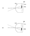
図5(A)は、焦点検出画素222aの一つを拡大して示す正面図、図7(A)は、焦点検出画素222aの断面図である。また、図5(B)は、焦点検出画素222bの一つを拡大して示す正面図、図7(B)は、焦点検出画素222bの断面図である。焦点検出画素222aは、図5(A)に示すように、マイクロレンズ2221aと、半円形状の光電変換部2222aとから構成され、図7(A)の断面図に示すように、撮像素子22の半導体回路基板2213の表面に光電変換部2222aが造り込まれ、その表面にマイクロレンズ2221aが形成されている。また、焦点検出画素222bは、図5(B)に示すように、マイクロレンズ2221bと、光電変換部2222bとから構成され、図7(B)の断面図に示すように、撮像素子22の半導体回路基板2213の表面に光電変換部2222bが造り込まれ、その表面にマイクロレンズ2221bが形成されている。そして、これら焦点検出画素222aおよび222bは、図3に示すように、互いに隣接して交互に、横一列に配列されることにより、図2に示す焦点検出画素列22a〜22eを構成する。
FIG. 5A is an enlarged front view showing one of the
なお、焦点検出画素222a,222bの光電変換部2222a,2222bは、マイクロレンズ2221a,2221bにより撮影光学系の射出瞳の所定の領域(たとえばF2.8)を通過する光束を受光するような形状とされる。また、焦点検出画素222a,222bにはカラーフィルタは設けられておらず、その分光特性は、光電変換を行うフォトダイオードの分光特性と、図示しない赤外カットフィルタの分光特性を総合したものとなっている。ただし、撮像画素221と同じカラーフィルタのうちの一つ、たとえば緑フィルタを備えるように構成することもできる。
The
また、図5(A)、図5(B)に示す焦点検出画素222a,222bの光電変換部2222a,2222bは半円形状としたが、光電変換部2222a,2222bの形状はこれに限定されず、他の形状、たとえば、楕円形状、矩形状、多角形状とすることもできる。
In addition, although the
ここで、上述した焦点検出画素222a,222bの画素出力に基づいて撮影光学系の焦点状態を検出する、いわゆる位相差検出方式について説明する。
Here, a so-called phase difference detection method for detecting the focus state of the photographing optical system based on the pixel outputs of the
図8は、図3のVIII-VIII線に沿う断面図であり、撮影光軸L1近傍に配置され、互いに隣接する焦点検出画素222a−1,222b−1,222a−2,222b−2が、射出瞳34の測距瞳341,342から照射される光束AB1−1,AB2−1,AB1−2,AB2−2をそれぞれ受光していることを示している。なお、図8においては、複数の焦点検出画素222a,222bのうち、撮影光軸L1近傍に位置するもののみを例示して示したが、図8に示す焦点検出画素以外のその他の焦点検出画素についても、同様に、一対の測距瞳341,342から照射される光束をそれぞれ受光するように構成されている。
FIG. 8 is a cross-sectional view taken along the line VIII-VIII in FIG. 3. The focus detection pixels 222 a-1, 222 b-1, 222 a-2, and 222 b-2 that are arranged in the vicinity of the photographing
ここで、射出瞳34とは、撮影光学系の予定焦点面に配置された焦点検出画素222a,222bのマイクロレンズ2221a,2221bの前方の距離Dの位置に設定された像である。距離Dは、マイクロレンズの曲率、屈折率、マイクロレンズと光電変換部との距離などに応じて一義的に決まる値であって、この距離Dを測距瞳距離と称する。また、測距瞳341,342とは、焦点検出画素222a,222bのマイクロレンズ2221a,2221bにより、それぞれ投影された光電変換部2222a,2222bの像をいう。
Here, the
なお、図8において焦点検出画素222a−1,222b−1,222a−2,222b−2の配列方向は一対の測距瞳341,342の並び方向と一致している。
In FIG. 8, the arrangement direction of the
また、図8に示すように、焦点検出画素222a−1,222b−1,222a−2,222b−2のマイクロレンズ2221a−1,2221b−1,2221a−2,2221b−2は、撮影光学系の予定焦点面近傍に配置されている。そして、マイクロレンズ2221a−1,2221b−1,2221a−2,2221b−2の背後に配置された各光電変換部2222a−1,2222b−1,2222a−2,2222b−2の形状が、各マイクロレンズ2221a−1,2221b−1,2221a−2,2221b−2から測距距離Dだけ離れた射出瞳34上に投影され、その投影形状は測距瞳341,342を形成する。
As shown in FIG. 8, the
すなわち、測距距離Dにある射出瞳34上で、各焦点検出画素の光電変換部の投影形状(測距瞳341,342)が一致するように、各焦点検出画素におけるマイクロレンズと光電変換部の相対的位置関係が定められ、それにより各焦点検出画素における光電変換部の投影方向が決定されている。
In other words, on the
図8に示すように、焦点検出画素222a−1の光電変換部2222a−1は、測距瞳341を通過し、マイクロレンズ2221a−1に向う光束AB1−1によりマイクロレンズ2221a−1上に形成される像の強度に対応した信号を出力する。同様に、焦点検出画素222a−2の光電変換部2222a−2は測距瞳341を通過し、マイクロレンズ2221a−2に向う光束AB1−2によりマイクロレンズ2221a−2上に形成される像の強度に対応した信号を出力する。
As shown in FIG. 8, the
また、焦点検出画素222b−1の光電変換部2222b−1は測距瞳342を通過し、マイクロレンズ2221b−1に向う光束AB2−1によりマイクロレンズ2221b−1上に形成される像の強度に対応した信号を出力する。同様に、焦点検出画素222b−2の光電変換部2222b−2は測距瞳342を通過し、マイクロレンズ2221b−2に向う光束AB2−2によりマイクロレンズ2221b−2上に形成される像の強度に対応した信号を出力する。
Further, the
そして、上述した2種類の焦点検出画素222a,222bを、図3に示すように直線状に複数配置し、各焦点検出画素222a,222bの光電変換部2222a,2222bの出力を、測距瞳341と測距瞳342とのそれぞれに対応した出力グループにまとめることにより、測距瞳341と測距瞳342とのそれぞれを通過する焦点検出光束が焦点検出画素列上に形成する一対の像の強度分布に関するデータが得られる。そして、この強度分布データに対し、相関演算処理または位相差検出処理などの像ズレ検出演算処理を施すことにより、いわゆる位相差検出方式による像ズレ量を検出することができる。
Then, a plurality of the above-described two types of
そして、得られた像ズレ量に一対の測距瞳の重心間隔に応じた変換演算を施すことにより、予定焦点面に対する現在の焦点面(予定焦点面上のマイクロレンズアレイの位置に対応した焦点検出位置における焦点面をいう。)の偏差、すなわちデフォーカス量を求めることができる。 Then, a conversion calculation is performed on the obtained image shift amount according to the center-of-gravity interval of the pair of distance measuring pupils, thereby obtaining a current focal plane with respect to the planned focal plane (the focal point corresponding to the position of the microlens array on the planned focal plane). The deviation of the focal plane at the detection position, that is, the defocus amount can be obtained.
なお、これら位相差検出方式による像ズレ量の演算と、これに基づくデフォーカス量の演算は、カメラ制御部21により実行される。
The calculation of the image shift amount by the phase difference detection method and the calculation of the defocus amount based thereon are executed by the
また、カメラ制御部21は、撮像素子22の撮像画素221の出力を読み出し、読み出した画素出力に基づき、焦点評価値の演算を行う。この焦点評価値は、たとえば撮像素子22の撮像画素221からの画像出力の高周波成分を、高周波透過フィルタを用いて抽出し、これを積算することで求めることができる。また、遮断周波数が異なる2つの高周波透過フィルタを用いて高周波成分を抽出し、それぞれを積算することでも求めることができる。
Further, the
そして、カメラ制御部21は、レンズ制御部37に制御信号を送出してフォーカスレンズ32を所定のサンプリング間隔(距離)で駆動させ、それぞれの位置における焦点評価値を求め、該焦点評価値が最大となるフォーカスレンズ32の位置を合焦位置として求める、コントラスト検出方式による焦点検出を実行する。なお、この合焦位置は、たとえば、フォーカスレンズ32を駆動させながら焦点評価値を算出した場合に、焦点評価値が、2回上昇した後、さらに、2回下降して推移した場合に、これらの焦点評価値を用いて、内挿法などの演算を行うことで求めることができる。
Then, the
ここで、図2には、撮影画面内の第1領域と第2領域とを、撮像素子22に対応させて表示している(なお、図2に示す一点鎖線で囲まれた領域が、第1領域であり、この第1領域の周囲に位置する外側の領域が第2領域である)。撮影画面の第1領域は、撮像素子22のうち、撮像画素221と、焦点検出画素列22a〜22eを構成する焦点検出画素222a,222bとを有する部分に対応しており、第1領域においては、光学系の焦点状態を位相差検出方式およびコントラスト検出方式により検出することが可能となっている。また、撮影画面の第2領域は、図2に示すように、撮影画面の第1領域の周囲に位置し、撮像素子22のうち、撮像画素221のみを有する部分に対応している。そのため、第2領域においては、光学系の焦点状態をコントラスト検出方式のみにより検出することが可能となっている。
Here, in FIG. 2, the first area and the second area in the shooting screen are displayed in correspondence with the image sensor 22 (note that the area surrounded by the one-dot chain line shown in FIG. 1 area, and the outer area located around the first area is the second area). The first area of the shooting screen corresponds to a part of the
次いで、本実施形態に係るカメラ1の動作例を説明する。図9は、本実施形態に係るカメラ1の動作例を示すフローチャートである。なお、以下の動作は、カメラ1の電源がオンされることにより開始される。また、以下においては、人物の顔領域を検出し、検出した人物の顔領域における焦点状態を検出するモードが選択されており、かつ、ワンショットモード、すなわち、一度調節したフォーカスレンズ32の位置を固定し、そのフォーカスレンズ位置で撮影するモードが選択されている場合を例示して説明を行なう。
Next, an operation example of the
さらに、以下においては、図10および図11を参照して、本実施形態に係るカメラ1の動作例を説明する。ここで、図10は、特定被写体が特定されていない場合の焦点検出方法を説明するための図であり、特定被写体が特定されていない場合において、電子ビューファインダ26により表示される撮影画面の一例を示している。また、図11は、特定被写体が特定されている場合の焦点検出方法を説明するための図であり、特定被写体が特定されている場合において、電子ビューファインダ26により表示される撮影画面の一例を示している。
Further, an operation example of the
図10および図11に示す例では、図10に示すように、撮影画面内に16個の焦点検出エリアAFP(図10中、破線で囲まれたエリア)が設定されており、16個の全ての焦点検出エリアAFPにおいて、位相差検出方式によるデフォーカス量の算出が可能となっている。なお、図10では、16個の焦点検出エリアAFPを例示しているが、撮影画面に設定される焦点検出エリアAFPの数は、16個に限定されるものではなく、15個以下とすることもできるし、17個以上とすることもできる。また、図10においては、説明の便宜のため、16個の焦点検出エリアAFPを破線で示しているが、本実施形態では、図11に示すように、焦点検出エリアAFPを撮影画面に表示しない構成とできる。 In the example shown in FIGS. 10 and 11, as shown in FIG. 10, 16 focus detection areas AFP (area surrounded by a broken line in FIG. 10) are set in the shooting screen. In the focus detection area AFP, it is possible to calculate the defocus amount by the phase difference detection method. In FIG. 10, 16 focus detection areas AFP are illustrated, but the number of focus detection areas AFP set on the shooting screen is not limited to 16, but 15 or less. Or 17 or more. In FIG. 10, for convenience of explanation, the 16 focus detection areas AFP are indicated by broken lines, but in this embodiment, as shown in FIG. 11, the focus detection areas AFP are not displayed on the shooting screen. Can be configured.
まず、ステップS101では、カメラ制御部21によるスルー画像の生成、および観察光学系の電子ビューファインダ26による、スルー画像の表示が開始される。具体的には、撮像素子22により露光動作が行なわれ、カメラ制御部21により、撮像画素221の画素データの読み出しが行なわれる。そして、カメラ制御部21は、読み出したデータに基づきスルー画像を生成し、生成されたスルー画像は液晶駆動回路25に送出され、観察光学系の電子ビューファインダ26に表示される。そして、これにより、接眼レンズ27を介して、撮影者は被写体の画像を視認することが可能となる。また、本実施形態では、図10および図11に示すように、カメラ制御部21により、撮影画面内の第1領域を示す第1領域マーク50が被写体の像に重畳され、第1領域マーク50が重畳されたスルー画像が、電子ビューファインダ26により表示される。なお、スルー画像の生成、およびスルー画像の表示は、所定の間隔で繰り返し実行される。
First, in step S101, generation of a through image by the
ステップS102では、カメラ制御部21により、撮影画面を複数の領域に分割し、分割した各領域ごとに測光を行う多分割測光(マルチパターン測光)が行われ、撮影画面全体の輝度値Bvが算出される。そして、カメラ制御部21により、算出した撮影画面全体の輝度値Bvに基づいて、撮影画面全体で適正露出が得られるように、受光感度Sv、露光時間Tv、および絞りAvが決定される。なお、本実施形態では、受光感度Svおよび露光時間Tvを優先して変更し、受光感度Svおよび露光時間Tvを変更するだけでは、撮影画面全体で適正露出が得られない場合に、絞りAvが変更される。
In step S102, the
ステップS103では、カメラ制御部21により、撮像素子22により撮像された撮像画像の中から人物の顔領域を検出する処理が行われる。たとえば、カメラ制御部21は、予め記憶している人物の顔のテンプレート画像データ(基準画像データ)と、撮像された撮像画像とを比較することにより、撮像画像の中から人物の顔領域を検出することができる。たとえば、図11に示す例では、第1領域を示す第1領域マーク50の範囲内において、人物の顔領域A,Bが検出され、第1領域を示す第1領域マーク50の範囲を超えた範囲内において、人物の顔領域Cが検出される。なお、ステップS103の人物の顔領域の検出は、所定の間隔で繰り返し行われる。
In step S <b> 103, the
ステップS104では、カメラ制御部21により、ステップS103で検出された人物の顔領域に、人物の顔領域を認識するための認識枠52が重畳され、人物の顔領域に認識枠52を重畳したスルー画像が、図11に示すように、電子ビューファインダ26により表示される。たとえば、図11に示す例では、3人の人物の顔領域A,B,Cが検出されており、検出された全ての人物の顔領域A,B,Cに対して、各人物の顔領域A,B,Cの位置および大きさに合わせた認識枠52が重畳される。
In step S104, a
なお、ステップS103で人物の顔領域が検出されなかった場合には、撮影者により予め設定されている焦点検出エリアAFPを示すマークを表示する構成としてもよいし、あるいは、撮影画面の中心において焦点検出を行うモードにおいては、撮影画面の中心の焦点検出エリアAFPを示すマークを表示する構成としてもよい。また、このような焦点検出エリアを示すマークを表示しない構成としてもよい。 If no human face area is detected in step S103, a mark indicating the focus detection area AFP preset by the photographer may be displayed, or the focus may be displayed at the center of the shooting screen. In the detection mode, a mark indicating the focus detection area AFP at the center of the shooting screen may be displayed. Moreover, it is good also as a structure which does not display the mark which shows such a focus detection area.
ステップS105では、カメラ制御部21により、操作部28に備えられたシャッターレリーズボタンの半押し(第1スイッチSW1のオン)がされたかどうかの判断が行なわれる。シャッターレリーズボタンが半押しされた場合は、ステップS106に進む。一方、シャッターレリーズボタンが半押しされていない場合は、ステップS102に戻り、露出制御と、人物の顔領域の検出とが繰り返し実行される。
In step S105, the
ステップS106では、カメラ制御部21により、人物の顔領域が検出されているか否かの判定が行われる。人物の顔領域が検出されている場合には、検出された人物の顔領域における焦点状態を検出するために、ステップS116に進み、一方、人物の顔領域が検出されていない場合には、第1領域マーク50の範囲内における焦点状態を検出するために、ステップS107に進む。
In step S106, the
ステップS107では、人物の顔領域が検出されていないため、カメラ制御部21により、焦点検出を行うための領域が、位相差検出方式による焦点検出が可能な第1領域に設定される。そして、続くステップS108では、カメラ制御部21により、第1領域内に設定された複数の焦点検出エリアAFPにおいて、位相差検出方式によるデフォーカス量の算出が行われる。たとえば、図10に示す例では、第1領域内に16個の焦点検出エリアAFPが設定されており、16個の全ての焦点検出エリアAFPにおいて、デフォーカス量の算出が行われる。
In step S107, since the face area of the person has not been detected, the
ステップS109では、カメラ制御部21により、デフォーカス量が算出できたか否かの判断が行われる。デフォーカス量が算出できた場合には、測距可能と判断して、ステップS110に進み、一方、デフォーカス量が算出できなかった場合には、測距不能と判断して、ステップS115に進む。なお、本実施形態では、第1領域マーク50が示す範囲内に設定された複数の焦点検出エリアAFPのうち、デフォーカス量が算出できた焦点検出エリアが1つでもある場合には、デフォーカス量が算出できたと判断されて、ステップS110に進み、一方、第1領域マーク50が示す範囲内に設定された全ての焦点検出エリアAFPでデフォーカス量が算出できない場合には、デフォーカス量が算出できないものと判断されて、ステップS115に進む。なお、本実施形態においては、デフォーカス量の算出ができた場合でも、算出されたデフォーカス量の信頼性が低い場合には、デフォーカス量が算出できなかったものとして扱い、ステップS115に進むこととする。本実施形態においては、たとえば、被写体のコントラストが低い場合、被写体が超低輝度被写体である場合、あるいは被写体が超高輝度被写体である場合などにおいて、デフォーカス量の信頼性が低いと判断される。
In step S109, the
ステップS110では、デフォーカス量が算出できたと判断されているため、カメラ制御部21により、ステップS108のデフォーカス量の演算結果に基づいて、焦点調節を行うための焦点検出エリアAFPを決定する処理が行われる。たとえば、至近側の被写体に優先してピントを合わせる至近優先モードが選択されている場合には、カメラ制御部21は、デフォーカス量が算出できた複数の焦点検出エリアAFPのうち、最も至近側の焦点検出エリアAFPを、焦点調節を行うための焦点検出エリアAFPとして決定する。また、焦点調節を行うための焦点検出エリアAFPの決定方法は、上記方法に限定されず、たとえば、デフォーカス量が算出できた複数の焦点検出エリアAFPのうち、撮影画面の中心から最も近い焦点検出エリアAFPを、焦点調節を行うための焦点検出エリアAFPとして決定することもできる。
Since it is determined in step S110 that the defocus amount has been calculated, the
そして、ステップS111では、図10に示すように、カメラ制御部21により、ステップS110で決定された焦点調節を行うための焦点検出エリアAFPに、焦点検出マーク51が重畳され、電子ビューファインダ26により表示される。これにより、本実施形態では、撮影者に、どの焦点検出エリアAFPが、焦点調節を行うための焦点検出エリアAFPであるかを視認させることができる。
In step S111, as shown in FIG. 10, the
ステップS112では、カメラ制御部21により、ステップS110で決定された、焦点調節を行うための焦点検出エリアAFPで算出されたデフォーカス量に基づいて、フォーカスレンズ32を合焦位置まで駆動させるのに必要となるレンズ駆動量の算出が行われ、算出されたレンズ駆動量が、レンズ制御部37を介して、フォーカスレンズ駆動モータ36に送出される。これにより、フォーカスレンズ駆動モータ36により、算出されたレンズ駆動量に基づいて、フォーカスレンズ32の駆動が行われる。
In step S112, the
そして、フォーカスレンズ32の合焦位置への駆動が完了すると、ステップS113に進み、合焦表示が行なわれ、次いで、ステップS114で、合焦ロック(フォーカスレンズ32の駆動を禁止する処理)が行なわれる。なお、ステップS113における合焦表示は、たとえば、電子ビューファインダ26により行われる。
When the driving of the
また、ステップS109で、デフォーカス量が算出できないと判断された場合には、ステップS115に進む。ステップS115では、カメラ制御部21により、スキャン動作を実行するスキャン動作実行処理が行なわれる。ここで、スキャン動作とは、フォーカスレンズ駆動モータ36により、フォーカスレンズ32をスキャン駆動させながら、カメラ制御部21により、位相差検出方式によるデフォーカス量の算出、および焦点評価値の算出を、所定の間隔で同時に行い、これにより、位相差検出方式による合焦位置の検出と、コントラスト検出方式による合焦位置の検出とを、同時に実行する動作である。以下においては、図12を参照して、本実施形態に係るスキャン動作実行処理を説明する。なお、図12は、本実施形態に係るスキャン動作実行処理を示すフローチャートである。
If it is determined in step S109 that the defocus amount cannot be calculated, the process proceeds to step S115. In step S115, the
まず、ステップS201では、カメラ制御部21により、スキャン動作の開始処理が行われる。具体的には、カメラ制御部21は、レンズ制御部37にスキャン駆動開始指令を送出し、レンズ制御部37は、カメラ制御部21からの指令に基づき、フォーカスレンズ駆動モータ36を駆動させ、フォーカスレンズ32を光軸L1に沿ってスキャン駆動させる。なお、スキャン駆動を行う方向は特に限定されず、フォーカスレンズ32のスキャン駆動を、無限端から至近端に向かって行なってもよいし、あるいは、至近端から無限端に向かって行なってもよい。
First, in step S201, the
そして、カメラ制御部21は、フォーカスレンズ32を駆動させながら、撮像素子22の焦点検出画素222a,222bから一対の像に対応した一対の像データの読み出しを行い、これに基づき、位相差検出方式により、デフォーカス量の算出および算出されたデフォーカス量の信頼性の評価を行うとともに、フォーカスレンズ32を駆動させながら、撮像素子22の撮像画素221から画素出力の読み出しを行い、これに基づき、焦点評価値を算出し、これにより、異なるフォーカスレンズ位置における焦点評価値を取得することで、コントラスト検出方式により合焦位置の検出を行う。
The
また、スキャン動作を行う際には、第1領域内における焦点状態を検出するために、第1領域において、位相差検出方式による焦点検出と、コントラスト検出方式による焦点検出とを行う。すなわち、スキャン動作を行う際には、第2領域において、コントラスト検出方式による焦点検出を行わない。ただし、スキャン動作において、第1領域に加えて、第2領域においても、コントラスト検出方式による焦点検出を行う構成とすることもできる。 When performing the scanning operation, in order to detect the focus state in the first region, focus detection by the phase difference detection method and focus detection by the contrast detection method are performed in the first region. That is, when performing the scanning operation, focus detection by the contrast detection method is not performed in the second region. However, in the scanning operation, the focus detection by the contrast detection method may be performed in the second region in addition to the first region.
ステップS202では、カメラ制御部21により、スキャン動作を行なった結果、第1領域において、位相差検出方式によりデフォーカス量が算出できたか否かの判定が行なわれる。第1領域において、位相差検出方式により、デフォーカス量が算出できた場合には、測距可能と判断して、ステップS205に進み、一方、デフォーカス量が算出できなかった場合には、測距不能と判断して、ステップS203に進む。
In step S202, it is determined whether or not the defocus amount can be calculated by the phase difference detection method in the first region as a result of the scanning operation performed by the
ステップS203では、カメラ制御部21により、スキャン動作を行なった結果、第1領域において、コントラスト検出方式により、合焦位置の検出ができたか否かの判定が行なわれる。第1領域において、コントラスト検出方式により、合焦位置の検出ができた場合には、ステップS211に進み、一方、合焦位置の検出ができなかった場合には、ステップS204に進む。
In step S203, as a result of the scanning operation performed by the
ステップS204では、カメラ制御部21により、スキャン動作を、フォーカスレンズ32の駆動可能範囲の全域について行なったか否かの判定が行なわれる。フォーカスレンズ32の駆動可能範囲の全域について、スキャン動作を行なっていない場合には、ステップS202に戻り、ステップS202〜S204を繰り返すことにより、スキャン動作、すなわち、フォーカスレンズ32をスキャン駆動させながら、位相差検出方式によるデフォーカス量の算出、およびコントラスト検出方式による合焦位置の検出を同時に実行するスキャン動作を継続して行なう。一方、フォーカスレンズ32の駆動可能範囲の全域について、スキャン動作の実行を完了している場合には、ステップS215に進む。
In step S <b> 204, the
そして、スキャン動作を実行した結果、ステップS202において、第1領域で、位相差検出方式によりデフォーカス量が算出できたと判定された場合には、ステップS205に進み、カメラ制御部21により、スキャン動作の停止処理が行なわれる。そして、ステップS206では、特定被写体が特定されているか否かの判断が行われる。図10に示すように、特定被写体が特定されていない場合には、ステップS207に進み、焦点調節を行うための焦点検出エリアAFPが決定され、焦点調節を行うための焦点検出エリアAFPに、焦点検出マーク51が重畳されて、電子ビューファインダ26により表示される。なお、ステップS206で、特定被写体が特定されている場合には、図11に示すように、既に、特定された特定被写体の位置において、焦点検出マーク53が重畳されているため(詳細は後述する。)、そのまま、ステップS208に進む。
As a result of executing the scanning operation, when it is determined in step S202 that the defocus amount can be calculated by the phase difference detection method in the first region, the process proceeds to step S205, and the
ステップS208では、位相差検出方式により算出されたデフォーカス量に基づいて、フォーカスレンズ32が合焦位置まで駆動される。そして、フォーカスレンズ32の合焦位置への駆動が完了すると、ステップS209に進み、合焦表示が行われた後、ステップS210で、合焦ロック(フォーカスレンズ32の駆動を禁止する処理)が行われる。
In step S208, the
また、スキャン動作を実行した結果、ステップS203において、第1領域で、コントラスト検出方式により、合焦位置が検出できたと判定された場合には、ステップS211に進み、カメラ制御部21により、スキャン動作の停止処理が行なわれる。そして、ステップS212では、ステップS206と同様に、特定被写体が特定されているか否かの判断が行われる。図10に示すように、特定被写体が特定されていない場合には、ステップS213に進み、合焦位置が検出されたエリアに、焦点検出マーク51が重畳されて、電子ビューファインダ26により表示される。なお、ステップS212においても、ステップS206と同様に、特定被写体が特定されている場合には、特定被写体の位置において既に焦点検出マーク53が重畳されているため、そのままステップS214に進む。
If it is determined in step S203 that the in-focus position has been detected by the contrast detection method in step S203 as a result of executing the scanning operation, the process proceeds to step S211 and the
ステップS214では、第1領域で検出された合焦位置に基づいて、フォーカスレンズ32が、合焦位置まで駆動される。そして、フォーカスレンズ32の合焦位置への駆動が完了すると、ステップS209に進み、合焦表示が行われ、ステップS210で、合焦ロック(フォーカスレンズ32の駆動を禁止する処理)が行われる。
In step S214, the
一方、ステップS204において、フォーカスレンズ32の駆動可能範囲の全域について、スキャン動作の実行が完了していると判定された場合には、ステップS215に進む。ステップS215では、スキャン動作を行なった結果、位相差検出方式およびコントラスト検出方式のいずれの方式によっても、焦点検出を行うことができなかったため、スキャン動作の終了処理が行なわれ、次いで、ステップS216に進み、カメラ制御部21により、合焦不能表示が行われる。なお、合焦不能表示は、たとえば、電子ビューファインダ26により行われる。
On the other hand, if it is determined in step S204 that the scan operation has been completed for the entire driveable range of the
また、図9に戻り、ステップS106で、人物の顔領域が検出されていると判定された場合には、ステップS116に進む。ステップS116では、カメラ制御部21により、ステップS103で検出された人物の顔領域に基づいて、焦点調節を行うための特定被写体の特定が行われる。
Returning to FIG. 9, if it is determined in step S106 that a human face area has been detected, the process proceeds to step S116. In step S116, the
たとえば、図11に示すように、ステップS103において複数の人物の顔領域が検出された場合には、カメラ制御部21は、これら複数の人物の顔領域のうち、大きさが最も大きい人物の顔領域を主要被写体であると判断し、大きさが最も大きい人物の顔領域を、焦点検出を行うための特定被写体として特定する。たとえば、図11に示す例では、3人の人物の顔領域A,B,Cが検出されており、これら3人の人物の顔領域A,B,Cのうち、大きさが最も大きい顔領域Bが、焦点検出を行うための特定被写体として特定される。なお、特定被写体を特定する方法は、上記方法に限定されず、たとえば、複数の人物の顔領域のうち、撮影画面の中心から最も近くに位置する人物の顔領域を、焦点検出を行うための特定被写体として特定してもよいし、あるいは、人物の顔領域の大きさと撮影画面の中心からの位置との組み合わせに基づいて、特定被写体を特定してもよい。また、操作部28を介して、撮影者により、複数の人物の顔領域の中から、焦点検出を行うための人物の顔領域が選択された場合には、撮影者により選択された人物の顔領域を、焦点検出を行うための特定被写体として特定してもよい。
For example, as shown in FIG. 11, when a plurality of human face areas are detected in step S <b> 103, the
ステップS117では、カメラ制御部21により、ステップS116で特定された特定被写体の像に、特定被写体の位置を示す焦点検出マーク53が重畳され、図11に示すように、焦点検出マーク53が重畳されたスルー画像が、電子ビューファインダ26により表示される。これにより、電子ビューファインダ26を介して、撮影者に、焦点検出を行うための特定被写体を視認させることができる。たとえば、図11に示す例では、3人の人物の顔領域A,B,Cのうち、撮影画面の中央に位置する顔領域Bが、焦点検出を行うための特定被写体として特定されているため、図11に示すように、特定被写体として特定された顔領域Bの像に、焦点検出マーク53が重畳される。なお、特定被写体を示す焦点検出マーク53は、特定被写体が、第1領域マーク50の示す範囲内を超えた範囲に存在する場合でも、特定被写体の像に重畳して表示される。たとえば、図11に示す例において、特定被写体として特定された人物の顔領域が、顔領域Cである場合でも、特定被写体として特定された人物の顔領域Cの像に、焦点検出マーク53が重畳される。
In step S117, the
次いで、ステップS118では、カメラ制御部21により、ステップS116で特定された特定被写体が、位相差検出方式により焦点検出が可能な第1領域内に存在するか否かの判断が行われる。特定被写体が第1領域内に存在すると判断された場合は、第1領域内の特定被写体の位置において、位相差検出方式による焦点検出を行うために、ステップS119に進む。一方、特定被写体が、コントラスト検出方式による焦点検出が可能な第2領域内に存在すると判断された場合には、第2領域内の特定被写体の位置において、コントラスト検出方式による焦点検出を行うため、ステップS121に進む。たとえば、図11に示す例では、撮影画面の中央に位置する人物の顔領域Bが特定被写体として特定されているため、特定被写体が第1領域内に存在すると判断され、ステップS119に進む。また、図11に示す例において、たとえば、撮影画面の右側に位置する人物の顔領域Cが特定被写体として特定されている場合には、特定被写体が第2領域内に存在すると判断され、ステップS121に進むこととなる。
Next, in step S118, the
ステップS119では、特定被写体が、位相差検出方式による焦点検出が可能な第1領域内に存在していると判断されているため、第1領域内の特定被写体の位置に対応する焦点検出エリアAFPにおいて、位相差検出方式による焦点検出が行われる。具体的には、まず、撮像素子22により、光学系からの光束の受光が行われ、カメラ制御部21により、第1領域内の特定被写体の位置に対応する焦点検出エリアAFPの焦点検出画素222a,222bから、一対の像に対応した一対の像データの読み出しが行われる。そして、カメラ制御部21は、読み出された一対の像データに基づいて像ズレ検出演算処理(相関演算処理)を実行し、算出した像ズレ量をデフォーカス量に変換する。また、カメラ制御部21は、ステップS109と同様に、算出したデフォーカス量の信頼性の評価も行う。
In step S119, since it is determined that the specific subject exists in the first area where focus detection can be performed by the phase difference detection method, the focus detection area AFP corresponding to the position of the specific subject in the first area. The focus detection by the phase difference detection method is performed. Specifically, first, the
そして、ステップS120では、ステップS109と同様に、ステップS119のデフォーカス量の演算結果に基づいて、デフォーカス量が算出できたか否かの判定が行なわれる。デフォーカス量が算出できた場合には、測距可能と判断して、ステップS122に進み、一方、デフォーカス量が算出できなかった場合には、測距不能と判断して、ステップS125に進む。なお、ステップS120においても、ステップS109と同様に、デフォーカス量の算出ができた場合でも、算出されたデフォーカス量の信頼性が低い場合には、デフォーカス量が算出できなかったものとして扱われる。 In step S120, as in step S109, it is determined whether the defocus amount has been calculated based on the defocus amount calculation result in step S119. If the defocus amount can be calculated, it is determined that distance measurement is possible and the process proceeds to step S122. On the other hand, if the defocus amount cannot be calculated, it is determined that distance measurement is not possible and the process proceeds to step S125. . In step S120, as in step S109, even if the defocus amount can be calculated, if the reliability of the calculated defocus amount is low, the defocus amount cannot be calculated. Is called.
また、ステップS118で、焦点検出を行うための特定被写体が、位相差検出方式による焦点検出が可能な第1領域に存在せずに、コントラスト検出方式による焦点検出が可能な第2領域に存在すると判断された場合には、ステップS121に進む。ステップS121では、カメラ制御部21により、第2領域内に存在する特定被写体の位置において、コントラスト検出方式による焦点検出が行われる。具体的には、カメラ制御部21は、フォーカスレンズ32を所定のサンプリング間隔で駆動させながら、第2領域内に存在する特定被写体の位置において、焦点評価値を繰り返し算出することで、焦点評価値が最大となるフォーカスレンズ32の位置を合焦位置として検出する。合焦位置を検出した後は、ステップS122に進む。
In step S118, the specific subject for focus detection does not exist in the first region where focus detection can be performed using the phase difference detection method, but exists in the second region where focus detection can be performed using the contrast detection method. If it is determined, the process proceeds to step S121. In step S121, the
そして、ステップS122では、カメラ制御部21により、ステップS119で算出されたデフォーカス量、または、ステップS121で検出された合焦位置に基づいて、フォーカスレンズ32を、合焦位置まで駆動するためのレンズ駆動量が算出され、算出されたレンズ駆動量に基づいて、フォーカスレンズ32の駆動が行われる。そして、フォーカスレンズ32の合焦位置への駆動が完了すると、ステップS123に進み、合焦表示が行われた後、ステップS124で、合焦ロック(フォーカスレンズ32の駆動を禁止する処理)が行われる。
In step S122, the
また、ステップS120で、第1領域内の特定被写体の位置で、デフォーカス量が算出できなかった場合には、ステップS125に進む。ステップS125では、ステップS115と同様に、スキャン動作実行処理が行われる。なお、ステップS125のスキャン動作実行処理においては、焦点調節を行うための特定被写体が特定されており、特定被写体に対応する位置に焦点検出マーク53が表示されている。そのため、スキャン動作において、デフォーカス量が算出された場合や、合焦位置が検出された場合には、デフォーカス量が算出された焦点検出エリア、あるいは、合焦位置が検出された合焦エリアを示す焦点検出マークの表示は行われない(ステップS206=No、ステップS212=No)。
In step S120, if the defocus amount cannot be calculated at the position of the specific subject in the first area, the process proceeds to step S125. In step S125, a scan operation execution process is performed as in step S115. In the scan operation execution process in step S125, a specific subject for focus adjustment is specified, and a
以上のように、本実施形態では、シャッターレリーズボタンが半押しされた際に、人物の顔などの特定被写体が特定されていない場合には、位相差検出方式による焦点検出が可能な第1領域において、位相差検出方式による焦点検出が行われる。このように、本実施形態では、特定被写体が特定されていない場合に、コントラスト検出方式による焦点検出と比べて、焦点検出に要する時間が短い、位相差検出方式による焦点検出が行われるため、特定被写体が特定されていない場合における、焦点検出に要する時間を短縮することができ、動体などの被写体への追従性を向上することができる。 As described above, in the present embodiment, when a specific subject such as a person's face is not specified when the shutter release button is pressed halfway, the first region in which focus detection can be performed by the phase difference detection method. The focus detection by the phase difference detection method is performed. As described above, in the present embodiment, when a specific subject is not specified, focus detection is performed by the phase difference detection method in which the time required for focus detection is short compared to the focus detection by the contrast detection method. When the subject is not specified, the time required for focus detection can be shortened, and the followability to a subject such as a moving object can be improved.
また、本実施形態では、シャッターレリーズボタンが半押しされた際に、特定被写体が特定されている場合には、特定被写体の位置に拘わらず、特定被写体に対する焦点検出が行われる。具体的には、特定被写体が、位相差検出方式による焦点検出が可能な第1領域に存在する場合には、第1領域に存在する特定被写体の位置において、位相差検出方式による焦点検出が行われ、一方、特定被写体が、コントラスト検出方式による焦点検出が可能な第2領域に存在する場合には、第2領域に存在する特定被写体の位置において、コントラスト検出方式による焦点検出が行われる。これにより、本実施形態では、特定被写体が特定された場合には、特定被写体が、第1領域に存在するか、あるいは第2領域に存在するかに拘わらず、特定被写体の位置において焦点状態を検出することができるため、特定被写体が特定された場合には、特定被写体にピントの合った画像を適切に撮像することができる。 In the present embodiment, when a specific subject is specified when the shutter release button is half-pressed, focus detection is performed on the specific subject regardless of the position of the specific subject. Specifically, when the specific subject exists in the first area where focus detection can be performed by the phase difference detection method, focus detection by the phase difference detection method is performed at the position of the specific subject existing in the first area. On the other hand, when the specific subject exists in the second region where focus detection can be performed by the contrast detection method, focus detection by the contrast detection method is performed at the position of the specific subject existing in the second region. Thus, in this embodiment, when a specific subject is specified, the focus state is changed at the position of the specific subject regardless of whether the specific subject exists in the first region or the second region. Therefore, when a specific subject is specified, it is possible to appropriately capture an image focused on the specific subject.
なお、本実施形態では、特定被写体が、位相差検出方式による焦点検出が可能な第1領域から、コントラスト検出方式による焦点検出が可能な第2領域へと移動した場合には、位相差検出方式による焦点検出から、コントラスト検出方式による焦点検出に切り替えて、焦点検出が行われる。また、反対に、特定被写体が、コントラスト検出方式による焦点検出が可能な第2領域から、位相差検出方式による焦点検出が可能な第1領域へと移動した場合にも、コントラスト検出方式による焦点検出から、位相差検出方式による焦点検出に切り替えて、焦点検出が行われる。 In the present embodiment, when the specific subject moves from the first area where focus detection is possible using the phase difference detection method to the second area where focus detection is possible using the contrast detection method, the phase difference detection method is used. The focus detection is performed by switching from the focus detection by the focus detection to the focus detection by the contrast detection method. On the other hand, when the specific subject moves from the second region where the focus detection by the contrast detection method can be performed to the first region where the focus detection by the phase difference detection method can be performed, the focus detection by the contrast detection method. Then, focus detection is performed by switching to focus detection by the phase difference detection method.
さらに、本実施形態では、第1領域において、位相差検出方式による焦点検出が可能であることに加えて、コントラスト検出方式による焦点検出も可能となっているが、第1領域においては、位相差検出方式による焦点検出が優先して行われる。このように、本実施形態では、第1領域において、位相差検出方式による焦点検出を優先して行うことで、焦点検出に要する時間を短縮することができ、動体などの特定被写体に対する追従性を向上することができる。 Furthermore, in the present embodiment, in addition to the focus detection by the phase difference detection method being possible in the first region, the focus detection by the contrast detection method is also possible, but in the first region, the phase difference is being detected. Focus detection by the detection method is performed with priority. As described above, in the present embodiment, in the first region, focus detection by the phase difference detection method is performed with priority, so that the time required for focus detection can be shortened, and the followability to a specific subject such as a moving object can be reduced. Can be improved.
なお、以上説明した実施形態は、本発明の理解を容易にするために記載されたものであって、本発明を限定するために記載されたものではない。したがって、上記の実施形態に開示された各要素は、本発明の技術的範囲に属する全ての設計変更や均等物をも含む趣旨である。 The embodiment described above is described for facilitating the understanding of the present invention, and is not described for limiting the present invention. Therefore, each element disclosed in the above embodiment is intended to include all design changes and equivalents belonging to the technical scope of the present invention.
たとえば、上述した実施形態では、特定被写体が特定されていない場合には、図10に示すように、複数の焦点検出エリアAFPの中から、焦点調節を行うための焦点検出エリアAFPを決定し、決定した焦点検出エリアAFPにおけるデフォーカス量に基づいて、フォーカスレンズ32を駆動させる構成を例示したが、この構成に特に限定されるものではなく、たとえば、複数の焦点検出エリアAFPで算出された複数のデフォーカス量の平均値を算出し、算出したデフォーカス量の平均値に基づいて、フォーカスレンズ32を駆動させる構成としてもよい。また、焦点検出エリアAFPの撮影画面内の位置や、算出されたデフォーカス量の信頼性に応じて、デフォーカス量に重み付けを行い、重み付けしたデフォーカス量の平均値に基づいて、フォーカスレンズ32を駆動させる構成としてもよい。
For example, in the above-described embodiment, when a specific subject is not specified, a focus detection area AFP for performing focus adjustment is determined from a plurality of focus detection areas AFP as shown in FIG. Although the configuration in which the
また、上述した実施形態では、人物の顔領域を検出し、検出した人物の顔領域を、焦点検出を行うための特定被写体として特定しているが、特定被写体は人物の顔領域に限定されず、たとえば、人物の目領域や動物の顔領域などを、特定被写体として特定することもできる。また、撮影者の手動操作により、あるいは、カメラ制御部21による被写体認識処理により指定された対象に対応するテンプレート画像を生成し、撮影画像の中から、生成されたテンプレート画像との一致度が所定以上であるエリアの探索を行い、一致度が所定以上であるエリアを繰り返し認識する追尾動作が行われている場合には、該追尾動作において追尾対象とされた被写体を、特定被写体として特定する構成としてもよい。
In the above-described embodiment, a human face area is detected and the detected human face area is specified as a specific subject for focus detection. However, the specific subject is not limited to the human face area. For example, a person's eye area or an animal face area can be specified as the specific subject. Further, a template image corresponding to a target specified by a photographer's manual operation or by subject recognition processing by the
さらに、上述した実施形態では、図10に示すように、第1領域内に複数の焦点検出エリアAFPが予め設定されており、特定被写体が、第1領域内に存在する場合には、第1領域内の特定被写体の位置に対応する焦点検出エリアAFPにおいて、デフォーカス量を算出する構成を例示したが、この構成に限定されるものではなく、たとえば、焦点検出エリアAFPを予め設定することなく、特定被写体の位置に対応する焦点検出画素222a,222bの出力に基づいて、特定被写体の位置におけるデフォーカス量を算出する構成としてもよい。
Further, in the above-described embodiment, as shown in FIG. 10, when a plurality of focus detection areas AFP are set in advance in the first area, and the specific subject exists in the first area, the first area The configuration for calculating the defocus amount in the focus detection area AFP corresponding to the position of the specific subject in the region is exemplified, but the configuration is not limited to this configuration. For example, the focus detection area AFP is not set in advance. The defocus amount at the position of the specific subject may be calculated based on the outputs of the
また、上述した実施形態では、スキャン動作を行う際に、位相差検出方式によりデフォーカス量が算出された場合、あるいは、コントラスト検出方式により合焦位置が検出された場合には、スキャン動作を停止して、フォーカスレンズ32を合焦位置まで駆動させる構成を例示したが、この構成に限定されるものではなく、たとえば、デフォーカス量が算出され、または、合焦位置が検出された場合でも、フォーカスレンズ32が所定のスキャン範囲をスキャンするまでは、スキャン動作を続行し、所定のスキャン範囲をスキャンした後に、算出されたデフォーカス量や、検出された合焦位置に基づいて、フォーカスレンズ32を駆動させる構成としてもよい。
In the above-described embodiment, when the defocus amount is calculated by the phase difference detection method or the in-focus position is detected by the contrast detection method when performing the scan operation, the scan operation is stopped. Then, the configuration for driving the
なお、上述した実施形態のカメラ1は特に限定されず、例えば、デジタルビデオカメラ、一眼レフデジタルカメラ、レンズ一体型のデジタルカメラ、携帯電話用のカメラなどのその他の光学機器に本発明を適用してもよい。
The
1…デジタルカメラ
2…カメラ本体
21…カメラ制御部
22…撮像素子
221…撮像画素
222a,222b…焦点検出画素
28…操作部
3…レンズ鏡筒
32…フォーカスレンズ
36…フォーカスレンズ駆動モータ
37…レンズ制御部
50…第1領域マーク
51,53…焦点検出マーク
52…識別枠
DESCRIPTION OF
Claims (8)
前記撮像素子から出力された信号に基づく画像から特定の被写体を特定する特定部と、
前記撮像素子から出力された信号に基づく画像の第1領域における前記光学系による像が前記撮像素子に合焦する前記焦点調節光学系の合焦位置と前記焦点調節光学系の位置とのずれ量を、前記撮像素子から出力される信号に基づいて検出する第1検出部と、
前記撮像素子から出力された信号に基づく画像の第1領域および前記第1領域以外の第2領域における像が前記撮像素子に合焦する前記焦点調節光学系の合焦位置を、前記撮像素子から出力される信号に基づいて検出する第2検出部と、
前記特定部により特定の被写体が特定されない場合、前記第1領域を前記焦点調節光学系の位置を検出する領域とし、前記第1検出部により前記ずれ量が検出できない場合、前記焦点調節光学系を移動させながら前記第1検出部により前記ずれ量を検出および前記第2検出部により前記合焦位置を検出させ、
前記特定部により特定の被写体が前記第1領域において特定されている場合、前記第1検出部により前記ずれ量を検出させ、前記特定部により前記特定の被写体が前記第2領域において特定されている場合、前記第2検出部により前記合焦位置を検出させる制御部と、を備える焦点検出装置。 And that an imaging device to output the signal by imaging an image formed by an optical system having a focusing optical system,
A specifying unit for specifying a specific subject from an image based on a signal output from the image sensor;
Deviation amount between the focus position of the focus adjustment optical system and the position of the focus adjustment optical system where the image by the optical system in the first region of the image based on the signal output from the image pickup element is focused on the image pickup element A first detection unit that detects a signal based on a signal output from the imaging device ;
The in- focus position of the focusing optical system where the image in the first region of the image based on the signal output from the image sensor and the second region other than the first region is in focus on the image sensor is determined from the image sensor. A second detector for detecting based on the output signal;
When the specific object is not specified by the specifying unit, the first region is set as a region for detecting the position of the focus adjusting optical system, and when the shift amount cannot be detected by the first detecting unit, the focus adjusting optical system is Detecting the shift amount by the first detector while detecting the in- focus position by the second detector while moving,
When a specific subject is specified in the first region by the specifying unit , the shift amount is detected by the first detection unit, and the specific subject is specified in the second region by the specifying unit. And a control unit that detects the in- focus position by the second detection unit.
前記制御部は、前記焦点調節光学系を移動させながら前記第1検出部および前記第2検出部により前記焦点調節光学系の位置を検出させ、前記第1検出部により前記ずれ量が検出されるとともに前記第2検出部により前記合焦位置が検出された場合、前記ずれ量に基づいて前記焦点調節光学系を移動させる焦点検出装置。 The focus detection apparatus according to claim 1,
Wherein, by the first detector and the second detector while moving the pre SL focal optics to detect the position of the focusing optical system, the shift amount is detected by the first detection unit And a focus detection device that moves the focus adjustment optical system based on the shift amount when the in-focus position is detected by the second detection unit .
前記制御部は、前記第1検出部により前記ずれ量を検出できた場合、前記ずれ量に基づいて前記焦点調節光学系を移動させ、前記第2検出部により前記合焦位置を検出できた場合、前記第2検出部の検出結果に基づいて前記焦点調節光学系を移動させる焦点検出装置。 The focus detection apparatus according to claim 1 or 2,
Wherein the control unit, when it is detected that the shift amount by the first detection unit, based on the amount of deviation by moving the focal optics, when it is detected that the focus position by the second detector A focus detection apparatus that moves the focus adjustment optical system based on a detection result of the second detection unit.
前記撮像素子は、焦点検出画素と撮像画素とを有し、
前記第1検出部は、前記焦点検出画素から出力される信号に基づいて前記ずれ量を検出し、前記第2検出部は前記撮像画素から出力される信号に基づく画像のコントラストに基づいて前記合焦位置を検出する焦点検出装置。 The focus detection apparatus according to any one of claims 1 to 3,
The imaging element has a focus detection pixel and an imaging pixel,
The first detection unit, based on the signal output from the pre-Symbol focus detection pixels to detect the shift amount, the second detector is based on the contrast of the image based on the signal output from the pre-Symbol imaging pixels A focus detection device for detecting the in- focus position .
前記制御部は、前記特定部により特定の被写体が特定されている場合、前記第1検出部または前記第2検出部に前記特定の被写体が前記撮像素子に合焦する前記焦点調節光学系の合焦位置を検出させる焦点検出装置。 The focus detection apparatus according to any one of claims 1 to 4,
Wherein, if a particular subject are specified by the specifying unit, the focal optics engagement of the specific subject in the first detector or the second detector is focused on the imaging device A focus detection device that detects the focal position.
前記撮像素子から出力された信号に基づく画像から被写体を選択する選択部を備え、
前記特定部は、前記選択部で選択された被写体を特定の被写体として特定する焦点検出装置。 The focus detection device according to any one of claims 1 to 5,
A selection unit for selecting a subject from an image based on a signal output from the image sensor;
The focus detection device that specifies the subject selected by the selection unit as a specific subject.
表示部を備え、
前記表示部は、前記第1領域を示す画像を、前記光学系を介して得られる画像に重畳して表示する焦点検出装置。 The focus detection apparatus according to any one of claims 1 to 6,
With a display,
The focus detection apparatus, wherein the display unit superimposes and displays an image indicating the first region on an image obtained through the optical system.
Priority Applications (1)
| Application Number | Priority Date | Filing Date | Title |
|---|---|---|---|
| JP2016028363A JP6183482B2 (en) | 2016-02-17 | 2016-02-17 | Focus detection apparatus and imaging apparatus |
Applications Claiming Priority (1)
| Application Number | Priority Date | Filing Date | Title |
|---|---|---|---|
| JP2016028363A JP6183482B2 (en) | 2016-02-17 | 2016-02-17 | Focus detection apparatus and imaging apparatus |
Related Parent Applications (1)
| Application Number | Title | Priority Date | Filing Date |
|---|---|---|---|
| JP2011146202A Division JP2013015559A (en) | 2011-06-30 | 2011-06-30 | Focus detector and imaging apparatus |
Publications (2)
| Publication Number | Publication Date |
|---|---|
| JP2016122210A JP2016122210A (en) | 2016-07-07 |
| JP6183482B2 true JP6183482B2 (en) | 2017-08-23 |
Family
ID=56327421
Family Applications (1)
| Application Number | Title | Priority Date | Filing Date |
|---|---|---|---|
| JP2016028363A Active JP6183482B2 (en) | 2016-02-17 | 2016-02-17 | Focus detection apparatus and imaging apparatus |
Country Status (1)
| Country | Link |
|---|---|
| JP (1) | JP6183482B2 (en) |
Families Citing this family (1)
| Publication number | Priority date | Publication date | Assignee | Title |
|---|---|---|---|---|
| JP6873779B2 (en) * | 2017-03-28 | 2021-05-19 | キヤノン株式会社 | Imaging device, its control method, and control program |
Family Cites Families (11)
| Publication number | Priority date | Publication date | Assignee | Title |
|---|---|---|---|---|
| JP4795155B2 (en) * | 2006-07-28 | 2011-10-19 | キヤノン株式会社 | Optical device, imaging device, and control method thereof |
| JP5098259B2 (en) * | 2006-09-04 | 2012-12-12 | 株式会社ニコン | camera |
| JP2008309882A (en) * | 2007-06-12 | 2008-12-25 | Nikon Corp | Digital camera |
| JP4957435B2 (en) * | 2007-07-30 | 2012-06-20 | 株式会社ニコン | Imaging device |
| JP4900134B2 (en) * | 2007-08-16 | 2012-03-21 | 株式会社ニコン | Focus adjustment device, camera |
| JP5176483B2 (en) * | 2007-10-30 | 2013-04-03 | 株式会社ニコン | Image recognition device, image tracking device, and imaging device |
| JP2010015024A (en) * | 2008-07-04 | 2010-01-21 | Canon Inc | Image pickup apparatus, control method thereof, program and storage medium |
| JP5543098B2 (en) * | 2008-11-14 | 2014-07-09 | キヤノン株式会社 | Imaging device |
| JP5390871B2 (en) * | 2009-01-26 | 2014-01-15 | キヤノン株式会社 | Imaging apparatus and control method thereof |
| JP5234099B2 (en) * | 2010-12-20 | 2013-07-10 | 株式会社ニコン | Autofocus device |
| JP2013015559A (en) * | 2011-06-30 | 2013-01-24 | Nikon Corp | Focus detector and imaging apparatus |
-
2016
- 2016-02-17 JP JP2016028363A patent/JP6183482B2/en active Active
Also Published As
| Publication number | Publication date |
|---|---|
| JP2016122210A (en) | 2016-07-07 |
Similar Documents
| Publication | Publication Date | Title |
|---|---|---|
| JP6019556B2 (en) | Focus detection device, imaging device, and camera. | |
| JP2013015559A (en) | Focus detector and imaging apparatus | |
| JP2012255910A (en) | Imaging apparatus | |
| JP2013050690A (en) | Focus adjusting device and imaging apparatus | |
| JP6477744B2 (en) | interchangeable lens | |
| JP6187617B2 (en) | Imaging device | |
| JP5929060B2 (en) | Focus detection apparatus and imaging apparatus | |
| JP5891667B2 (en) | Focus adjustment device and imaging device provided with the same | |
| JP6399140B2 (en) | Imaging device | |
| JP5891668B2 (en) | Focus adjustment device and imaging device | |
| JP5966262B2 (en) | Imaging device | |
| JP5477344B2 (en) | Focus adjustment device and imaging device provided with the same | |
| JP6183482B2 (en) | Focus detection apparatus and imaging apparatus | |
| JP2013061579A (en) | Focusing device and imaging apparatus | |
| JP6127730B2 (en) | Imaging device | |
| JP6069817B2 (en) | Focus adjustment device and imaging device provided with the same | |
| JP5454521B2 (en) | Imaging device | |
| JP6098690B2 (en) | Lens barrel and camera body | |
| JP2012247723A (en) | Focus adjustment device and imaging apparatus | |
| JP5821934B2 (en) | Focus detection device, camera body, and camera | |
| JP5423734B2 (en) | Lens barrel and imaging device | |
| JP5561246B2 (en) | Focus adjustment device and imaging device provided with the same | |
| JP5402997B2 (en) | Focus adjustment device and imaging device provided with the same | |
| JP2012181448A (en) | Focusing device and imaging apparatus | |
| JP6332372B2 (en) | Focus adjustment device and imaging device provided with the same |
Legal Events
| Date | Code | Title | Description |
|---|---|---|---|
| A977 | Report on retrieval |
Free format text: JAPANESE INTERMEDIATE CODE: A971007 Effective date: 20161031 |
|
| A131 | Notification of reasons for refusal |
Free format text: JAPANESE INTERMEDIATE CODE: A131 Effective date: 20161122 |
|
| A521 | Request for written amendment filed |
Free format text: JAPANESE INTERMEDIATE CODE: A523 Effective date: 20170123 |
|
| TRDD | Decision of grant or rejection written | ||
| A01 | Written decision to grant a patent or to grant a registration (utility model) |
Free format text: JAPANESE INTERMEDIATE CODE: A01 Effective date: 20170627 |
|
| A61 | First payment of annual fees (during grant procedure) |
Free format text: JAPANESE INTERMEDIATE CODE: A61 Effective date: 20170710 |
|
| R150 | Certificate of patent or registration of utility model |
Ref document number: 6183482 Country of ref document: JP Free format text: JAPANESE INTERMEDIATE CODE: R150 |
|
| R250 | Receipt of annual fees |
Free format text: JAPANESE INTERMEDIATE CODE: R250 |
|
| R250 | Receipt of annual fees |
Free format text: JAPANESE INTERMEDIATE CODE: R250 |
|
| R250 | Receipt of annual fees |
Free format text: JAPANESE INTERMEDIATE CODE: R250 |
|
| R250 | Receipt of annual fees |
Free format text: JAPANESE INTERMEDIATE CODE: R250 |
|
| R250 | Receipt of annual fees |
Free format text: JAPANESE INTERMEDIATE CODE: R250 |