JP6399140B2 - Imaging device - Google Patents

Imaging device Download PDF

Info

Publication number
JP6399140B2
JP6399140B2 JP2017079473A JP2017079473A JP6399140B2 JP 6399140 B2 JP6399140 B2 JP 6399140B2 JP 2017079473 A JP2017079473 A JP 2017079473A JP 2017079473 A JP2017079473 A JP 2017079473A JP 6399140 B2 JP6399140 B2 JP 6399140B2
Authority
JP
Japan
Prior art keywords
focus
lens
optical system
imaging device
image
Prior art date
Legal status (The legal status is an assumption and is not a legal conclusion. Google has not performed a legal analysis and makes no representation as to the accuracy of the status listed.)
Active
Application number
JP2017079473A
Other languages
Japanese (ja)
Other versions
JP2017151458A5 (en
JP2017151458A (en
Inventor
朗 木下
朗 木下
Current Assignee (The listed assignees may be inaccurate. Google has not performed a legal analysis and makes no representation or warranty as to the accuracy of the list.)
Nikon Corp
Original Assignee
Nikon Corp
Priority date (The priority date is an assumption and is not a legal conclusion. Google has not performed a legal analysis and makes no representation as to the accuracy of the date listed.)
Filing date
Publication date
Application filed by Nikon Corp filed Critical Nikon Corp
Priority to JP2017079473A priority Critical patent/JP6399140B2/en
Publication of JP2017151458A publication Critical patent/JP2017151458A/en
Publication of JP2017151458A5 publication Critical patent/JP2017151458A5/ja
Application granted granted Critical
Publication of JP6399140B2 publication Critical patent/JP6399140B2/en
Active legal-status Critical Current
Anticipated expiration legal-status Critical

Links

Images

Description

本発明は、撮像装置に関する。   The present invention relates to an imaging apparatus.

従来より、ズーム動作時に被写体にピントの合った画像を撮影するために、ズームレンズの移動に合わせてフォーカスレンズを移動させる撮像装置が知られている(たとえば、特許文献1参照)。   2. Description of the Related Art Conventionally, there has been known an imaging apparatus that moves a focus lens in accordance with the movement of a zoom lens in order to capture an image that is focused on a subject during a zoom operation (see, for example, Patent Document 1).

特開2002−228913号公報JP 2002-228913 A

しかしながら、従来技術は、所定の設計値で設計されたズームレンズとフォーカスレンズとに合わせて、このようなズームレンズの位置とフォーカスレンズの位置との関係を示すズームトラッキング用のテーブルを予め記憶しておき、記憶されたズームトラッキング用のテーブルに基づいて、フォーカスレンズを駆動させるものであるため、ズームレンズまたはフォーカスレンズの実測値とレンズ設計値との間に誤差が生じている場合に、ズーム動作時において、被写体にピントの合った画像を撮影できない場合があった。   However, the conventional technology stores in advance a zoom tracking table indicating the relationship between the position of the zoom lens and the position of the focus lens in accordance with the zoom lens and the focus lens designed with predetermined design values. Since the focus lens is driven based on the stored zoom tracking table, if there is an error between the actual value of the zoom lens or focus lens and the lens design value, zoom During operation, there was a case where an image focused on the subject could not be taken.

本発明が解決しようとする課題は、好適な焦点調節制御が可能な撮像装置を提供することである。   The problem to be solved by the present invention is to provide an imaging apparatus capable of suitable focus adjustment control.

本発明は、以下の解決手段によって上記課題を解決する。なお、以下においては、本発明の実施形態を示す図面に対応する符号を付して説明するが、この符号は発明の理解を容易にするためだけのものであって発明を限定する趣旨ではない。   The present invention solves the above problems by the following means. In the following description, reference numerals corresponding to the drawings showing the embodiment of the present invention are given and described. However, the reference numerals are only for facilitating the understanding of the invention and are not intended to limit the invention. .

[1]本発明に係る撮像装置は、ズームレンズとフォーカスレンズとを有する光学系による像を合焦させる前記フォーカスレンズの合焦位置を検出する検出部と、前記検出部により前記合焦位置を検出する、前記光学系の像面における位置を選択する選択部と、を備え、前記検出部は、前記光学系の像面において前記光学系の光軸を含む第1領域以外の第2領域に含まれる位置が前記選択部により選択されている場合に、前記ズームレンズが移動すると、前記第1領域に含まれる位置に合焦する前記合焦位置を検出し、前記ズームレンズが停止すると、前記合焦位置を検出する位置を前記第2領域に含まれる位置に設定して前記合焦位置を検出する。
[2]本発明に係る撮像装置は、ズームレンズとフォーカスレンズとを有する光学系による像を合焦させる前記フォーカスレンズの合焦位置を検出する検出部と、前記検出部により前記合焦位置を検出する、前記光学系の像面における位置を選択する選択部と、を備え、前記検出部は、前記光学系の像面において前記光学系の光軸を含む第1領域以外の第2領域に含まれる位置が前記選択部により選択されている場合に、前記ズームレンズが移動すると、前記第1領域に含まれる位置に合焦する前記合焦位置を検出し、前記ズームレンズが停止すると、前記ズームレンズが移動する前に前記第2領域に含まれる位置にいた被写体に近い被写体に合焦する前記合焦位置を検出する。
[3]上記撮像装置に係る発明において、前記検出部は、前記第2領域に含まれる位置が選択されている場合に前記ズームレンズが移動すると、前記合焦位置を検出する位置を前記第1領域に含まれる位置に設定して前記合焦位置を検出することができる。
[4]上記撮像装置に係る発明において、前記検出部は、前記第1領域に含まれる位置が前記選択部により選択されている場合、前記第1領域に含まれる位置に合焦する前記合焦位置を検出することができる。
[5]上記撮像装置に係る発明において、前記検出部は、前記光学系の像面の位置が、前記選択部により選択された位置における前記光学系の焦点深度の3倍の範囲内となる像面の位置に合焦する前記合焦位置を検出することができる。
[6]上記撮像装置に係る発明において、前記検出部は、前記選択部により選択された位置との前記光学系の像面のずれ量が、前記光学系の焦点深度の3倍の範囲内となる像面の位置に合焦する前記合焦位置を検出することができる。
[7]上記撮像装置に係る発明において、前記検出部は、前記光学系の像面において前記光学系の光軸の位置に合焦する前記合焦位置を検出することができる。
[8]上記撮像装置に係る発明において、前記検出部は、前記選択部により選択された前記第2領域に含まれる位置に近い前記第1領域に含まれる位置に合焦する前記合焦位置を検出することができる。
[9]上記撮像装置に係る発明において、前記検出部は、前記フォーカスレンズの位置と前記合焦位置とのずれ量を検出することができる。
[10]上記撮像装置に係る発明において、前記光学系による像を撮像して信号を出力する撮像部を備え、前記検出部は前記撮像部から出力された信号に基づいて、前記光学系による像が前記撮像部に合焦する合焦位置を検出することができる。
[11]上記撮像装置に係る発明において、前記検出部で検出された前記合焦位置に前記フォーカスレンズの位置を制御する制御部を備えることができる。
[12]上記撮像装置に係る発明において、前記制御部は、前記検出部により前記合焦位置が検出されない場合、前記ズームレンズと前記フォーカスレンズとの位置関係に基づいて、前記フォーカスレンズの位置を制御することができる。
[13]上記撮像装置に係る発明において、前記制御部は、前記検出部により前記合焦位置が検出されない場合、前記ズームレンズの移動量に基づいて、前記フォーカスレンズの位置を制御することができる。
[1] An imaging apparatus according to the present invention includes a detection unit that detects an in-focus position of the focus lens that focuses an image by an optical system having a zoom lens and a focus lens, and the in-focus position is determined by the detection unit. And a selection unit that selects a position on the image plane of the optical system to detect, the detection unit in a second region other than the first region including the optical axis of the optical system on the image plane of the optical system. When the included position is selected by the selection unit, when the zoom lens moves, the in-focus position that focuses on the position included in the first region is detected, and when the zoom lens stops, The position for detecting the focus position is set to a position included in the second region, and the focus position is detected.
[2] An imaging apparatus according to the present invention includes a detection unit that detects an in-focus position of the focus lens that focuses an image by an optical system having a zoom lens and a focus lens, and the in-focus position is determined by the detection unit. And a selection unit that selects a position on the image plane of the optical system to detect, the detection unit in a second region other than the first region including the optical axis of the optical system on the image plane of the optical system. When the included position is selected by the selection unit, when the zoom lens moves, the in-focus position that focuses on the position included in the first region is detected, and when the zoom lens stops, Before the zoom lens moves, the in-focus position for focusing on a subject close to the subject in the position included in the second region is detected.
[3] In the invention relating to the imaging apparatus, the detection unit may detect a position where the focus position is detected when the zoom lens moves when a position included in the second region is selected. The in-focus position can be detected by setting to a position included in the region.
[4] In the invention related to the imaging apparatus, the detection unit may focus on a position included in the first region when a position included in the first region is selected by the selection unit. The position can be detected.
[5] In the invention related to the imaging apparatus, the detection unit may be an image in which the position of the image plane of the optical system is within a range that is three times the focal depth of the optical system at the position selected by the selection unit. The in-focus position that focuses on the position of the surface can be detected.
[6] In the invention related to the imaging apparatus, the detection unit may be configured such that the amount of deviation of the image plane of the optical system from the position selected by the selection unit is within a range of three times the focal depth of the optical system. It is possible to detect the in-focus position that focuses on the position of the image plane.
[7] In the invention relating to the imaging apparatus, the detection unit may detect the in-focus position at which the optical axis of the optical system is focused on the image plane of the optical system.
[8] In the invention according to the imaging apparatus, the detection unit may determine the focus position that focuses on a position included in the first region that is close to a position included in the second region selected by the selection unit. Can be detected.
[9] In the invention according to the imaging apparatus, the detection unit can detect a shift amount between the position of the focus lens and the in-focus position.
[10] In the invention according to the imaging apparatus, the imaging unit includes an imaging unit that captures an image by the optical system and outputs a signal, and the detection unit performs an image by the optical system based on a signal output from the imaging unit. It is possible to detect a focus position at which the imaging unit is focused.
[11] In the invention relating to the imaging apparatus, a control unit that controls the position of the focus lens at the in-focus position detected by the detection unit may be provided.
[12] In the invention related to the imaging apparatus, the control unit determines the position of the focus lens based on a positional relationship between the zoom lens and the focus lens when the focus position is not detected by the detection unit. Can be controlled.
[13] In the invention related to the imaging apparatus, the control unit can control the position of the focus lens based on the movement amount of the zoom lens when the focus position is not detected by the detection unit. .

本発明によれば、好適な焦点調節制御が可能な撮像装置を提供することができる。   According to the present invention, it is possible to provide an imaging apparatus capable of suitable focus adjustment control.

図1は、本実施形態に係るカメラを示すブロック図である。FIG. 1 is a block diagram showing a camera according to the present embodiment. 図2は、図1に示す撮像素子の撮像面を示す正面図である。FIG. 2 is a front view showing an imaging surface of the imaging device shown in FIG. 図3は、図2のIII部を拡大して焦点検出画素222a,222bの配列を模式的に示す正面図である。FIG. 3 is a front view schematically showing the arrangement of the focus detection pixels 222a and 222b by enlarging the III part of FIG. 図4(A)は、撮像画素221の一つを拡大して示す正面図、図4(B)は、焦点検出画素222aの一つを拡大して示す正面図、図4(C)は、焦点検出画素222bの一つを拡大して示す正面図、図4(D)は、撮像画素221の一つを拡大して示す断面図、図4(E)は、焦点検出画素222aの一つを拡大して示す断面図、図4(F)は、焦点検出画素222bの一つを拡大して示す断面図である。4A is an enlarged front view showing one of the imaging pixels 221, FIG. 4B is an enlarged front view showing one of the focus detection pixels 222a, and FIG. FIG. 4D is an enlarged front view showing one of the focus detection pixels 222b, FIG. 4D is a cross-sectional view showing one of the imaging pixels 221 in an enlarged manner, and FIG. 4E is one of the focus detection pixels 222a. FIG. 4F is an enlarged sectional view showing one of the focus detection pixels 222b. 図5は、図3のV-V線に沿う断面図である。FIG. 5 is a cross-sectional view taken along the line VV in FIG. 図6は、撮影光学系の撮影画面50内に設定された焦点検出エリアの配置例を示す図である。FIG. 6 is a diagram illustrating an arrangement example of the focus detection areas set in the photographing screen 50 of the photographing optical system. 図7は、本実施形態に係るカメラの動作を示すフローチャートである。FIG. 7 is a flowchart showing the operation of the camera according to the present embodiment. 図8は、本実施形態に係るスキャン動作実行処理を示すフローチャートである。FIG. 8 is a flowchart showing scan operation execution processing according to the present embodiment.

以下、本発明の実施形態を図面に基づいて説明する。   Hereinafter, embodiments of the present invention will be described with reference to the drawings.

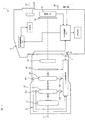
図1は、本発明の実施形態に係るデジタルカメラ1を示す要部構成図である。本実施形態のデジタルカメラ1(以下、単にカメラ1という。)は、カメラ本体2とレンズ鏡筒3から構成され、これらカメラ本体2とレンズ鏡筒3はマウント部4により着脱可能に結合されている。   FIG. 1 is a main part configuration diagram showing a digital camera 1 according to an embodiment of the present invention. A digital camera 1 according to the present embodiment (hereinafter simply referred to as a camera 1) includes a camera body 2 and a lens barrel 3, and the camera body 2 and the lens barrel 3 are detachably coupled by a mount unit 4. Yes.

レンズ鏡筒3は、カメラ本体2に着脱可能な交換レンズである。図1に示すように、レンズ鏡筒3には、レンズ31,32,33,34、および絞り35を含む撮影光学系が内蔵されている。   The lens barrel 3 is an interchangeable lens that can be attached to and detached from the camera body 2. As shown in FIG. 1, the lens barrel 3 includes a photographing optical system including lenses 31, 32, 33, 34 and a diaphragm 35.

レンズ32は、フォーカスレンズであり、光軸L1方向に移動することで、撮影光学系の焦点距離を調節可能となっている。フォーカスレンズ32は、レンズ鏡筒3の光軸L1に沿って移動可能に設けられ、フォーカスレンズ用エンコーダ321によってその位置が検出されつつフォーカスレンズ駆動モータ322によってその位置が調節される。   The lens 32 is a focus lens, and can adjust the focal length of the photographing optical system by moving in the direction of the optical axis L1. The focus lens 32 is provided so as to be movable along the optical axis L1 of the lens barrel 3, and its position is adjusted by the focus lens drive motor 322 while its position is detected by the focus lens encoder 321.

このフォーカスレンズ32の光軸L1に沿う移動機構の具体的構成は特に限定されない。一例を挙げれば、レンズ鏡筒3に固定された固定筒に回転可能に回転筒を挿入し、この回転筒の内周面にヘリコイド溝(螺旋溝)を形成するとともに、フォーカスレンズ32を固定するレンズ枠の端部をヘリコイド溝に嵌合させる。そして、フォーカスレンズ駆動モータ322によって回転筒を回転させることで、レンズ枠に固定されたフォーカスレンズ32が光軸L1に沿って直進移動することになる。   The specific configuration of the moving mechanism along the optical axis L1 of the focus lens 32 is not particularly limited. For example, a rotating cylinder is rotatably inserted into a fixed cylinder fixed to the lens barrel 3, a helicoid groove (spiral groove) is formed on the inner peripheral surface of the rotating cylinder, and the focus lens 32 is fixed. The end of the lens frame is fitted into the helicoid groove. Then, by rotating the rotating cylinder by the focus lens driving motor 322, the focus lens 32 fixed to the lens frame moves straight along the optical axis L1.

上述したようにレンズ鏡筒3に対して回転筒を回転させることによりレンズ枠に固定されたフォーカスレンズ32は光軸L1方向に直進移動するが、その駆動源としてのフォーカスレンズ駆動モータ322がレンズ鏡筒3に設けられている。フォーカスレンズ駆動モータ322と回転筒とは、たとえば複数の歯車からなる変速機で連結され、フォーカスレンズ駆動モータ322の駆動軸を何れか一方向へ回転駆動すると所定のギヤ比で回転筒に伝達され、そして、回転筒が何れか一方向へ回転することで、レンズ枠に固定されたフォーカスレンズ32が光軸L1の何れかの方向へ直進移動することになる。なお、フォーカスレンズ駆動モータ322の駆動軸が逆方向に回転駆動すると、変速機を構成する複数の歯車も逆方向に回転し、フォーカスレンズ32は光軸L1の逆方向へ直進移動することになる。   As described above, the focus lens 32 fixed to the lens frame by moving the rotating cylinder with respect to the lens barrel 3 moves straight in the direction of the optical axis L1, but the focus lens drive motor 322 as the drive source is the lens. The lens barrel 3 is provided. The focus lens drive motor 322 and the rotating cylinder are connected by a transmission composed of a plurality of gears, for example, and when the drive shaft of the focus lens driving motor 322 is driven to rotate in any one direction, it is transmitted to the rotating cylinder at a predetermined gear ratio. Then, when the rotating cylinder rotates in any one direction, the focus lens 32 fixed to the lens frame moves linearly in any direction of the optical axis L1. When the drive shaft of the focus lens drive motor 322 is rotated in the reverse direction, the plurality of gears constituting the transmission also rotate in the reverse direction, and the focus lens 32 moves straight in the reverse direction of the optical axis L1. .

フォーカスレンズ32の位置はフォーカスレンズ用エンコーダ321によって検出される。既述したとおり、フォーカスレンズ32の光軸L1方向の位置は回転筒の回転角に相関するので、たとえばレンズ鏡筒3に対する回転筒の相対的な回転角を検出すれば求めることができる。   The position of the focus lens 32 is detected by a focus lens encoder 321. As described above, the position of the focus lens 32 in the optical axis L1 direction correlates with the rotation angle of the rotating cylinder, and can be obtained by detecting the relative rotation angle of the rotating cylinder with respect to the lens barrel 3, for example.

本実施形態のフォーカスレンズ用エンコーダ321としては、回転筒の回転駆動に連結された回転円板の回転をフォトインタラプタなどの光センサで検出して、回転数に応じたパルス信号を出力するものや、固定筒と回転筒の何れか一方に設けられたフレキシブルプリント配線板の表面のエンコーダパターンに、何れか他方に設けられたブラシ接点を接触させ、回転筒の移動量(回転方向でも光軸方向の何れでもよい)に応じた接触位置の変化を検出回路で検出するものなどを用いることができる。   As the focus lens encoder 321 of this embodiment, the rotation of a rotating disk connected to the rotational drive of a rotating cylinder is detected by an optical sensor such as a photo interrupter, and a pulse signal corresponding to the number of rotations is output. The brush contact provided on either one of the encoder pattern on the surface of the flexible printed wiring board provided on one of the fixed cylinder and the rotating cylinder is brought into contact with the moving amount of the rotating cylinder (in the optical axis direction even in the rotation direction). Any of which can detect a change in the contact position according to the detection circuit by a detection circuit can be used.

フォーカスレンズ32は、上述した回転筒の回転によってカメラボディ側の端部(至近端ともいう)から被写体側の端部(無限端ともいう)までの間を光軸L1方向に移動することができる。ちなみに、フォーカスレンズ用エンコーダ321で検出されたフォーカスレンズ32の現在位置情報は、レンズ制御部36を介して後述するカメラ制御部21へ送出され、フォーカスレンズ駆動モータ322は、この情報に基づいて演算されたフォーカスレンズ32の駆動位置が、カメラ制御部21からレンズ制御部36を介して送出されることにより駆動する。   The focus lens 32 can move in the direction of the optical axis L1 from the end on the camera body side (also referred to as the closest end) to the end on the subject side (also referred to as the infinite end) by the rotation of the rotating cylinder described above. it can. Incidentally, the current position information of the focus lens 32 detected by the focus lens encoder 321 is sent to the camera control unit 21 (to be described later) via the lens control unit 36, and the focus lens drive motor 322 calculates based on this information. The focus lens 32 thus driven is driven by being sent from the camera control unit 21 via the lens control unit 36.

ズームレンズ33は、レンズ鏡筒2の光軸L1に沿って移動可能に設けられ、ズームレンズ用エンコーダ331によってその位置が検出されつつ、ズームレンズ駆動モータ332によってその位置が調節される。ズームレンズ33の位置は、例えば、撮影者によりレンズ鏡筒2のズーム環(不図示)が回されることによって変化し、それに応じて光学系の焦点距離が変わることとなる。そして、ズームレンズ用エンコーダ331で検出されたズームレンズ33の位置情報は、レンズ制御部36へ送信される。なお、ズームレンズ33の移動機構は、上述のフォーカスレンズ32の移動機構と同様とすればよく、さらに、ズームレンズ用エンコーダ331も、上述のフォーカスレンズ用エンコーダ321と同様のものを用いることができる。   The zoom lens 33 is provided so as to be movable along the optical axis L1 of the lens barrel 2, and its position is adjusted by the zoom lens drive motor 332 while its position is detected by the zoom lens encoder 331. The position of the zoom lens 33 changes, for example, when the photographer turns the zoom ring (not shown) of the lens barrel 2 and the focal length of the optical system changes accordingly. Then, the position information of the zoom lens 33 detected by the zoom lens encoder 331 is transmitted to the lens control unit 36. The moving mechanism of the zoom lens 33 may be the same as the moving mechanism of the focus lens 32 described above, and the zoom lens encoder 331 may be the same as the focus lens encoder 321 described above. .

絞り35は、上記撮影光学系を通過して撮像素子22に至る光束の光量を制限するとともにボケ量を調整するために、光軸L1を中心にした開口径が調節可能に構成されている。絞り35による開口径の調節は、たとえば自動露出モードにおいて演算された適切な開口径が、カメラ制御部21からレンズ制御部36を介して送出されることにより行われる。また、カメラ本体2に設けられた操作部28によるマニュアル操作により、設定された開口径がカメラ制御部21からレンズ制御部36に入力される。絞り35の開口径は図示しない絞り開口センサにより検出され、レンズ制御部36で現在の開口径が認識される。   The diaphragm 35 is configured such that the aperture diameter around the optical axis L1 can be adjusted in order to limit the amount of light flux that passes through the photographing optical system and reaches the image sensor 22 and adjust the amount of blur. The adjustment of the aperture diameter by the diaphragm 35 is performed, for example, by sending an appropriate aperture diameter calculated in the automatic exposure mode from the camera control unit 21 via the lens control unit 36. Further, the set aperture diameter is input from the camera control unit 21 to the lens control unit 36 by a manual operation by the operation unit 28 provided in the camera body 2. The aperture diameter of the aperture 35 is detected by an aperture sensor (not shown), and the lens controller 36 recognizes the current aperture diameter.

また、レンズ制御部36は、ズームレンズ用エンコーダ332によって検出されるズームレンズ33の位置を検出し、ズームレンズ33が駆動した場合には、ズームレンズ33の移動量に応じて、フォーカスレンズ32を駆動させて、フォーカスを微調整するズームトラッキング制御を行う。   The lens control unit 36 detects the position of the zoom lens 33 detected by the zoom lens encoder 332, and when the zoom lens 33 is driven, the lens control unit 36 moves the focus lens 32 according to the movement amount of the zoom lens 33. It is driven to perform zoom tracking control for fine adjustment of focus.

一方、カメラ本体2には、上記撮影光学系からの光束L1を受光する撮像素子22が、撮影光学系の予定焦点面に設けられ、その前面にシャッター23が設けられている。撮像素子22はCCDやCMOSなどのデバイスから構成され、受光した光信号を電気信号に変換してカメラ制御部21に送出する。カメラ制御部21に送出された撮影画像情報は、逐次、液晶駆動回路25に送出されて観察光学系の電子ビューファインダ(EVF)26に表示されるとともに、操作部28に備えられたレリーズボタン(不図示)が全押しされた場合には、その撮影画像情報が、記録媒体であるカメラメモリ24に記録される。なお、カメラメモリ24は着脱可能なカード型メモリや内蔵型メモリの何れをも用いることができる。撮像素子22の構造の詳細は後述する。   On the other hand, the camera body 2 is provided with an imaging element 22 that receives the light beam L1 from the photographing optical system on a planned focal plane of the photographing optical system, and a shutter 23 is provided on the front surface thereof. The image sensor 22 is composed of a device such as a CCD or CMOS, converts the received optical signal into an electrical signal, and sends it to the camera control unit 21. The captured image information sent to the camera control unit 21 is sequentially sent to the liquid crystal drive circuit 25 and displayed on the electronic viewfinder (EVF) 26 of the observation optical system, and a release button ( When (not shown) is fully pressed, the photographed image information is recorded in the camera memory 24 which is a recording medium. The camera memory 24 can be either a removable card type memory or a built-in memory. Details of the structure of the image sensor 22 will be described later.

カメラ本体2には、撮像素子22で撮像される像を観察するための観察光学系が設けられている。本実施形態の観察光学系は、液晶表示素子からなる電子ビューファインダ(EVF)26と、これを駆動する液晶駆動回路25と、接眼レンズ27とを備えている。液晶駆動回路25は、撮像素子22で撮像され、カメラ制御部21へ送出された撮影画像情報を読み込み、これに基づいて電子ビューファインダ26を駆動する。これにより、ユーザは、接眼レンズ27を通して現在の撮影画像を観察することができる。なお、光軸L2による上記観察光学系に代えて、または、これに加えて、液晶ディスプレイをカメラ本体2の背面等に設け、この液晶ディスプレイに撮影画像を表示させることもできる。   The camera body 2 is provided with an observation optical system for observing an image picked up by the image pickup device 22. The observation optical system of the present embodiment includes an electronic viewfinder (EVF) 26 composed of a liquid crystal display element, a liquid crystal driving circuit 25 that drives the electronic viewfinder (EVF) 26, and an eyepiece lens 27. The liquid crystal drive circuit 25 reads the captured image information captured by the image sensor 22 and sent to the camera control unit 21, and drives the electronic viewfinder 26 based on the read image information. Thereby, the user can observe the current captured image through the eyepiece lens 27. Note that, instead of or in addition to the observation optical system using the optical axis L2, a liquid crystal display may be provided on the back surface of the camera body 2, and a photographed image may be displayed on the liquid crystal display.

カメラ本体2にはカメラ制御部21が設けられている。カメラ制御部21は、マウント部4に設けられた電気信号接点部41によりレンズ制御部36と電気的に接続され、このレンズ制御部36からレンズ情報を受信するとともに、レンズ制御部36へデフォーカス量や絞り開口径などの情報を送信する。なお、レンズ制御部36から送信されるレンズ情報には、フォーカスレンズ32及びズームレンズ33の位置情報や、ズームレンズ33の駆動が行われていることを示すズーム動作信号などが含まれる。   A camera control unit 21 is provided in the camera body 2. The camera control unit 21 is electrically connected to the lens control unit 36 through an electrical signal contact unit 41 provided on the mount unit 4, receives lens information from the lens control unit 36, and defocuses to the lens control unit 36. Send information such as volume and aperture diameter. The lens information transmitted from the lens control unit 36 includes position information on the focus lens 32 and the zoom lens 33, a zoom operation signal indicating that the zoom lens 33 is being driven, and the like.

また、カメラ制御部21は、上述したように撮像素子22から画素出力を読み出すとともに、読み出した画素出力について、必要に応じて所定の情報処理を施すことにより画像情報を生成し、生成した画像情報を、電子ビューファインダ26の液晶駆動回路25やメモリ24に出力する。また、カメラ制御部21は、撮像素子22からの画像情報の補正やレンズ鏡筒3の焦点調節状態、絞り調節状態などを検出するなど、カメラ1全体の制御を司る。   The camera control unit 21 reads out the pixel output from the image sensor 22 as described above, generates image information by performing predetermined information processing on the read out pixel output as necessary, and generates the generated image information. Is output to the liquid crystal driving circuit 25 and the memory 24 of the electronic viewfinder 26. The camera control unit 21 controls the entire camera 1 such as correction of image information from the image sensor 22 and detection of a focus adjustment state and an aperture adjustment state of the lens barrel 3.

また、カメラ制御部21は、上記に加えて、撮像素子22から読み出した画素データに基づき、位相検出方式による撮影光学系の焦点状態の検出、およびコントラスト検出方式による撮影光学系の焦点状態の検出を行う。なお、具体的な焦点状態の検出方法については、後述する。   In addition to the above, the camera control unit 21 detects the focus state of the photographic optical system by the phase detection method and the focus state of the photographic optical system by the contrast detection method based on the pixel data read from the image sensor 22. I do. A specific focus state detection method will be described later.

操作部28は、シャッターレリーズボタンや、動画撮影開始スイッチなどの撮影者がカメラ1の各種動作モードを設定するための入力スイッチであり、オートフォーカスモード/マニュアルフォーカスモードの切換が行えるようになっている。この操作部28により設定された各種モードはカメラ制御部21へ送出され、当該カメラ制御部21によりカメラ1全体の動作が制御される。また、シャッターレリーズボタンは、ボタンの半押しでONとなる第1スイッチSW1と、ボタンの全押しでONとなる第2スイッチSW2とを含む。   The operation unit 28 is an input switch for a photographer to set various operation modes of the camera 1 such as a shutter release button and a moving image shooting start switch, and can switch between an auto focus mode and a manual focus mode. Yes. Various modes set by the operation unit 28 are sent to the camera control unit 21, and the operation of the entire camera 1 is controlled by the camera control unit 21. The shutter release button includes a first switch SW1 that is turned on when the button is half-pressed and a second switch SW2 that is turned on when the button is fully pressed.

次に、本実施形態に係る撮像素子22について説明する。   Next, the image sensor 22 according to the present embodiment will be described.

図2は、撮像素子22の撮像面を示す正面図、図3は、図2のIII部分を拡大して焦点検出画素222a,222bの配列を模式的に示す正面図である。   FIG. 2 is a front view showing the imaging surface of the imaging device 22, and FIG. 3 is a front view schematically showing the arrangement of the focus detection pixels 222a and 222b by enlarging the III part of FIG.

本実施形態の撮像素子22は、図3に示すように、複数の撮像画素221が、撮像面の平面上に二次元的に配列され、緑色の波長領域を透過するカラーフィルタを有する緑画素Gと、赤色の波長領域を透過するカラーフィルタを有する赤画素Rと、青色の波長領域を透過するカラーフィルタを有する青画素Bがいわゆるベイヤー配列(Bayer Arrangement)されたものである。すなわち、隣接する4つの画素群223(稠密正方格子配列)において一方の対角線上に2つの緑画素が配列され、他方の対角線上に赤画素と青画素が1つずつ配列されている。このベイヤー配列された画素群223を単位として、当該画素群223を撮像素子22の撮像面に二次元状に繰り返し配列することで撮像素子22が構成されている。   As shown in FIG. 3, the imaging element 22 of the present embodiment includes a green pixel G having a color filter in which a plurality of imaging pixels 221 are two-dimensionally arranged on the plane of the imaging surface and transmit a green wavelength region. A red pixel R having a color filter that transmits a red wavelength region and a blue pixel B having a color filter that transmits a blue wavelength region are arranged in a so-called Bayer Arrangement. That is, in four adjacent pixel groups 223 (dense square lattice arrangement), two green pixels are arranged on one diagonal line, and one red pixel and one blue pixel are arranged on the other diagonal line. The image sensor 22 is configured by repeatedly arranging the pixel group 223 on the imaging surface of the image sensor 22 in a two-dimensional manner with the Bayer array pixel group 223 as a unit.

なお、単位画素群223の配列は、図示する稠密正方格子以外にも、たとえば稠密六方格子配列にすることもできる。また、カラーフィルタの構成や配列はこれに限定されることはなく、補色フィルタ(緑:G、イエロー:Ye、マゼンタ:Mg,シアン:Cy)の配列を採用することもできる。   The unit pixel group 223 may be arranged in a dense hexagonal lattice arrangement other than the dense square lattice shown in the figure. Further, the configuration and arrangement of the color filters are not limited to this, and an arrangement of complementary color filters (green: G, yellow: Ye, magenta: Mg, cyan: Cy) can also be adopted.

図4(A)は、撮像画素221の一つを拡大して示す正面図、図4(D)は断面図である。一つの撮像画素221は、マイクロレンズ2211と、光電変換部2212と、図示しないカラーフィルタから構成され、図4(D)の断面図に示すように、撮像素子22の半導体回路基板2213の表面に光電変換部2212が造り込まれ、その表面にマイクロレンズ2211が形成されている。光電変換部2212は、マイクロレンズ2211により撮影光学系の射出瞳(たとえばF1.0)を通過する撮像光束を受光する形状とされ、撮像光束を受光する。   4A is an enlarged front view showing one of the imaging pixels 221 and FIG. 4D is a cross-sectional view. One imaging pixel 221 includes a microlens 2211, a photoelectric conversion unit 2212, and a color filter (not shown), and on the surface of the semiconductor circuit substrate 2213 of the imaging element 22 as shown in the cross-sectional view of FIG. A photoelectric conversion portion 2212 is built, and a microlens 2211 is formed on the surface thereof. The photoelectric conversion unit 2212 is configured to receive an imaging light beam that passes through an exit pupil (for example, F1.0) of the photographing optical system by the micro lens 2211, and receives the imaging light beam.

また、撮像素子22には、上述した撮像画素221に代えて焦点検出画素222a,222bが配列された複数の焦点検出画素列220が設けられている。そして、一つの焦点検出画素列220は、図3に示すように、複数の焦点検出画素222aおよび222bが、互いに隣接して交互に配列されて構成されている。本実施形態においては、焦点検出画素222aおよび222bは、ベイヤー配列された撮像画素221の緑画素Gと青画素Bとの位置にギャップを設けることなく密に配列されている。   In addition, the imaging element 22 is provided with a plurality of focus detection pixel rows 220 in which focus detection pixels 222a and 222b are arranged in place of the above-described imaging pixels 221. As shown in FIG. 3, one focus detection pixel row 220 includes a plurality of focus detection pixels 222 a and 222 b that are alternately arranged adjacent to each other. In the present embodiment, the focus detection pixels 222a and 222b are densely arranged without providing a gap at the position of the green pixel G and the blue pixel B of the image pickup pixel 221 arranged in the Bayer array.

図4(B)は、焦点検出画素222aの一つを拡大して示す正面図、図4(E)は、焦点検出画素222aの断面図である。また、図4(C)は、焦点検出画素222bの一つを拡大して示す正面図、図4(F)は、焦点検出画素222bの断面図である。焦点検出画素222aは、図4(B)に示すように、マイクロレンズ2221aと、半円形状の光電変換部2222aとから構成され、図4(E)の断面図に示すように、撮像素子22の半導体回路基板2213の表面に光電変換部2222aが造り込まれ、その表面にマイクロレンズ2221aが形成されている。また、焦点検出画素222bは、図4(C)に示すように、マイクロレンズ2221bと、光電変換部2222bとから構成され、図4(F)の断面図に示すように、撮像素子22の半導体回路基板2213の表面に光電変換部2222bが造り込まれ、その表面にマイクロレンズ2221bが形成されている。そして、これら焦点検出画素222aおよび222bは、図3に示すように、互いに隣接して交互に、横一列に配列されることにより、図2に示す焦点検出画素列220を構成する。   4B is an enlarged front view of one of the focus detection pixels 222a, and FIG. 4E is a cross-sectional view of the focus detection pixel 222a. 4C is an enlarged front view showing one of the focus detection pixels 222b, and FIG. 4F is a cross-sectional view of the focus detection pixel 222b. As shown in FIG. 4B, the focus detection pixel 222a includes a micro lens 2221a and a semicircular photoelectric conversion unit 2222a. As shown in the cross-sectional view of FIG. A photoelectric conversion portion 2222a is formed on the surface of the semiconductor circuit substrate 2213, and a micro lens 2221a is formed on the surface. The focus detection pixel 222b includes a micro lens 2221b and a photoelectric conversion unit 2222b as shown in FIG. 4C, and a semiconductor of the image sensor 22 as shown in the cross-sectional view of FIG. A photoelectric conversion unit 2222b is formed on the surface of the circuit board 2213, and a microlens 2221b is formed on the surface. Then, as shown in FIG. 3, these focus detection pixels 222a and 222b are alternately arranged adjacent to each other in a horizontal row to form a focus detection pixel row 220 shown in FIG.

なお、焦点検出画素222a,222bの光電変換部2222a,2222bは、マイクロレンズ2221a,2221bにより撮影光学系の射出瞳の所定の領域(たとえばF2.8)を通過する光束を受光するような形状とされる。また、焦点検出画素222a,222bにはカラーフィルタは設けられておらず、その分光特性は、光電変換を行うフォトダイオードの分光特性と、図示しない赤外カットフィルタの分光特性を総合したものとなっている。ただし、撮像画素221と同じカラーフィルタのうちの一つ、たとえば緑フィルタを備えるように構成することもできる。   The photoelectric conversion units 2222a and 2222b of the focus detection pixels 222a and 222b have such a shape that the microlenses 2221a and 2221b receive a light beam that passes through a predetermined region (eg, F2.8) of the exit pupil of the photographing optical system. Is done. Further, the focus detection pixels 222a and 222b are not provided with color filters, and their spectral characteristics are the total of the spectral characteristics of a photodiode that performs photoelectric conversion and the spectral characteristics of an infrared cut filter (not shown). ing. However, it may be configured to include one of the same color filters as the imaging pixel 221, for example, a green filter.

また、図4(B)、図4(C)に示す焦点検出画素222a,222bの光電変換部2222a,2222bは半円形状としたが、光電変換部2222a,2222bの形状はこれに限定されず、他の形状、たとえば、楕円形状、矩形状、多角形状とすることもできる。   In addition, although the photoelectric conversion units 2222a and 2222b of the focus detection pixels 222a and 222b illustrated in FIGS. 4B and 4C have a semicircular shape, the shape of the photoelectric conversion units 2222a and 2222b is not limited thereto. Other shapes such as an elliptical shape, a rectangular shape, and a polygonal shape can also be used.

ここで、上述した焦点検出画素222a,222bの画素出力に基づいて撮影光学系の焦点状態を検出する、いわゆる位相差検出方式について説明する。   Here, a so-called phase difference detection method for detecting the focus state of the photographing optical system based on the pixel outputs of the focus detection pixels 222a and 222b described above will be described.

図5は、図3のV-V線に沿う断面図であり、撮影光軸L1近傍に配置され、互いに隣接する焦点検出画素222a−1,222b−1,222a−2,222b−2が、射出瞳350の測距瞳351,352から照射される光束AB1−1,AB2−1,AB1−2,AB2−2をそれぞれ受光していることを示している。なお、図5においては、複数の焦点検出画素222a,222bのうち、撮影光軸L1近傍に位置するもののみを例示して示したが、図5に示す焦点検出画素以外のその他の焦点検出画素についても、同様に、一対の測距瞳351,352から照射される光束をそれぞれ受光するように構成されている。   FIG. 5 is a cross-sectional view taken along the line V-V in FIG. 3. It shows that light beams AB1-1, AB2-1, AB1-2, and AB2-2 irradiated from the distance measuring pupils 351 and 352 of the exit pupil 350 are received. In FIG. 5, only the focus detection pixels 222 a and 222 b that are located in the vicinity of the photographing optical axis L <b> 1 are illustrated, but other focus detection pixels other than the focus detection pixels illustrated in FIG. 5 are illustrated. In the same manner, the light beams emitted from the pair of distance measuring pupils 351 and 352 are respectively received.

ここで、射出瞳350とは、撮影光学系の予定焦点面に配置された焦点検出画素222a,222bのマイクロレンズ2221a,2221bの前方の距離Dの位置に設定された像である。距離Dは、マイクロレンズの曲率、屈折率、マイクロレンズと光電変換部との距離などに応じて一義的に決まる値であって、この距離Dを測距瞳距離と称する。また、測距瞳351,352とは、焦点検出画素222a,222bのマイクロレンズ2221a,2221bにより、それぞれ投影された光電変換部2222a,2222bの像をいう。   Here, the exit pupil 350 is an image set at a distance D in front of the microlenses 2221a and 2221b of the focus detection pixels 222a and 222b arranged on the planned focal plane of the photographing optical system. The distance D is a value uniquely determined according to the curvature and refractive index of the microlens, the distance between the microlens and the photoelectric conversion unit, and the distance D is referred to as a distance measurement pupil distance. The distance measurement pupils 351 and 352 are images of the photoelectric conversion units 2222a and 2222b respectively projected by the micro lenses 2221a and 2221b of the focus detection pixels 222a and 222b.

なお、図5において焦点検出画素222a−1,222b−1,222a−2,222b−2の配列方向は一対の測距瞳351,352の並び方向と一致している。   In FIG. 5, the arrangement direction of the focus detection pixels 222 a-1, 222 b-1, 222 a-2, and 222 b-2 coincides with the arrangement direction of the pair of distance measuring pupils 351 and 352.

また、図5に示すように、焦点検出画素222a−1,222b−1,222a−2,222b−2のマイクロレンズ2221a−1,2221b−1,2221a−2,2221b−2は、撮影光学系の予定焦点面近傍に配置されている。そして、マイクロレンズ2221a−1,2221b−1,2221a−2,2221b−2の背後に配置された各光電変換部2222a−1,2222b−1,2222a−2,2222b−2の形状が、各マイクロレンズ2221a−1,2221b−1,2221a−2,2221b−2から測距距離Dだけ離れた射出瞳350上に投影され、その投影形状は測距瞳351,352を形成する。   As shown in FIG. 5, the microlenses 2221a-1, 2221b-1, 2221a-2, and 2221b-2 of the focus detection pixels 222a-1, 222b-1, 222a-2, and 222b-2 are photographic optical systems. Near the planned focal plane. The shapes of the photoelectric conversion units 2222a-1, 2222b-1, 2222a-2, 2222b-2 arranged behind the micro lenses 2221a-1, 2221b-1, 2221a-2, 2221b-2 are the same as the micro lenses 2221a-1, 2221b-1, 2221a-2, 2221b-2. Projected onto the exit pupil 350 that is separated from the lenses 2221 a-1, 2221 b-1, 2221 a-2, and 2221 b-2 by a distance measurement distance D, and the projection shape forms distance measurement pupils 351 and 352.

すなわち、測距距離Dにある射出瞳350上で、各焦点検出画素の光電変換部の投影形状(測距瞳351,352)が一致するように、各焦点検出画素におけるマイクロレンズと光電変換部の相対的位置関係が定められ、それにより各焦点検出画素における光電変換部の投影方向が決定されている。   That is, the microlens and the photoelectric conversion unit in each focus detection pixel so that the projection shapes (distance measurement pupils 351 and 352) of the focus detection pixels coincide on the exit pupil 350 at the distance D. Is determined, and the projection direction of the photoelectric conversion unit in each focus detection pixel is thereby determined.

図5に示すように、焦点検出画素222a−1の光電変換部2222a−1は、測距瞳351を通過し、マイクロレンズ2221a−1に向う光束AB1−1によりマイクロレンズ2221a−1上に形成される像の強度に対応した信号を出力する。同様に、焦点検出画素222a−2の光電変換部2222a−2は測距瞳351を通過し、マイクロレンズ2221a−2に向う光束AB1−2によりマイクロレンズ2221a−2上に形成される像の強度に対応した信号を出力する。   As shown in FIG. 5, the photoelectric conversion unit 2222a-1 of the focus detection pixel 222a-1 is formed on the microlens 2221a-1 by a light beam AB1-1 that passes through the distance measuring pupil 351 and goes to the microlens 2221a-1. A signal corresponding to the intensity of the image to be output is output. Similarly, the photoelectric conversion unit 2222a-2 of the focus detection pixel 222a-2 passes through the distance measuring pupil 351, and the intensity of the image formed on the microlens 2221a-2 by the light beam AB1-2 toward the microlens 2221a-2. The signal corresponding to is output.

また、焦点検出画素222b−1の光電変換部2222b−1は測距瞳352を通過し、マイクロレンズ2221b−1に向う光束AB2−1によりマイクロレンズ2221b−1上に形成される像の強度に対応した信号を出力する。同様に、焦点検出画素222b−2の光電変換部2222b−2は測距瞳352を通過し、マイクロレンズ2221b−2に向う光束AB2−2によりマイクロレンズ2221b−2上に形成される像の強度に対応した信号を出力する。   Further, the photoelectric conversion unit 2222b-1 of the focus detection pixel 222b-1 passes through the distance measuring pupil 352, and the intensity of the image formed on the microlens 2221b-1 by the light beam AB2-1 directed to the microlens 2221b-1. Output the corresponding signal. Similarly, the photoelectric conversion unit 2222b-2 of the focus detection pixel 222b-2 passes through the distance measuring pupil 352, and the intensity of the image formed on the microlens 2221b-2 by the light beam AB2-2 toward the microlens 2221b-2. The signal corresponding to is output.

そして、上述した2種類の焦点検出画素222a,222bを、図3に示すように直線状に複数配置し、各焦点検出画素222a,222bの光電変換部2222a,2222bの出力を、測距瞳351と測距瞳352とのそれぞれに対応した出力グループにまとめることにより、測距瞳351と測距瞳352とのそれぞれを通過する焦点検出光束が焦点検出画素列上に形成する一対の像の強度分布に関するデータが得られる。そして、この強度分布データに対し、相関演算処理または位相差検出処理などの像ズレ検出演算処理を施すことにより、いわゆる位相差検出方式による像ズレ量を検出する。   Then, a plurality of the above-described two types of focus detection pixels 222a and 222b are arranged in a straight line as shown in FIG. 3, and the outputs of the photoelectric conversion units 2222a and 2222b of the focus detection pixels 222a and 222b are used as the distance measurement pupil 351. Of the pair of images formed on the focus detection pixel array by the focus detection light fluxes passing through each of the distance measurement pupil 351 and the distance measurement pupil 352. Data on the distribution is obtained. The intensity distribution data is subjected to an image shift detection calculation process such as a correlation calculation process or a phase difference detection process to detect an image shift amount by a so-called phase difference detection method.

そして、得られた像ズレ量に一対の測距瞳の重心間隔に応じた変換演算を施すことにより、予定焦点面に対する現在の焦点面(予定焦点面上のマイクロレンズアレイの位置に対応した焦点検出エリアにおける焦点面をいう。)の偏差、すなわちデフォーカス量を求めることができる。   Then, a conversion calculation is performed on the obtained image shift amount according to the center-of-gravity interval of the pair of distance measuring pupils, thereby obtaining a current focal plane with respect to the planned focal plane (the focal point corresponding to the position of the microlens array on the planned focal plane). The deviation of the focal plane in the detection area), that is, the defocus amount can be obtained.

なお、これら位相差検出方式による像ズレ量の演算およびデフォーカス量の演算はカメラ制御部21により実行される。   The calculation of the image shift amount and the calculation of the defocus amount by these phase difference detection methods are executed by the camera control unit 21.

また、本実施形態では、図2に示すように、51個の焦点検出画素列220が設けられており、図6に示すように、これら焦点検出画素列220のそれぞれの位置に対応して、撮影画面50上に、AFP1〜AFP51で示す51点の焦点検出エリアAFPが設定されている。カメラ制御部21は、これらの焦点検出エリアAFPに対応する焦点検出画素列220の出力に基づいて、それぞれの焦点検出エリアAFPにおけるデフォーカス量を算出する。なお、図6は、撮影光学系の撮影画面50内に設定された焦点検出エリアの配置の一例を示す図であり、焦点検出エリアAFPの個数および配置は、図6に示す態様に限定されるものではない。   Further, in the present embodiment, as shown in FIG. 2, 51 focus detection pixel columns 220 are provided, and as shown in FIG. 6, corresponding to the respective positions of these focus detection pixel columns 220, On the shooting screen 50, 51 focus detection areas AFP indicated by AFP1 to AFP51 are set. The camera control unit 21 calculates the defocus amount in each focus detection area AFP based on the output of the focus detection pixel row 220 corresponding to these focus detection areas AFP. FIG. 6 is a diagram showing an example of the arrangement of focus detection areas set in the imaging screen 50 of the imaging optical system, and the number and arrangement of the focus detection areas AFP are limited to the mode shown in FIG. It is not a thing.

また、カメラ制御部21は、これら複数の焦点検出エリアAFP1〜AFP51のうち、焦点調節を行うための焦点検出エリアを第1対象エリアとして設定し、第1対象エリアにおけるデフォーカス量に基づいて、フォーカスレンズ32を駆動させることで、光学系の焦点状態の調節を行う。たとえば、カメラ制御部21は、操作部28を介して撮影者がこれら複数の焦点検出エリアAFP1〜AFP51のうち焦点調節を行うための焦点検出エリアを選択した場合に、撮影者に選択された焦点検出エリアAFPを第1対象エリアとして設定することができる。また、カメラ制御部21は、たとえば、最も至近側にある焦点検出エリアや撮影画面50内において中央部分に位置する焦点検出エリアを自動で、第1対象エリアとして設定してもよい。   Further, the camera control unit 21 sets a focus detection area for performing focus adjustment among the plurality of focus detection areas AFP1 to AFP51 as a first target area, and based on the defocus amount in the first target area, The focus state of the optical system is adjusted by driving the focus lens 32. For example, when the photographer selects a focus detection area for performing focus adjustment among the plurality of focus detection areas AFP1 to AFP51 via the operation unit 28, the camera control unit 21 selects the focus selected by the photographer. The detection area AFP can be set as the first target area. The camera control unit 21 may automatically set, for example, the focus detection area that is closest to the camera or the focus detection area that is located in the center of the shooting screen 50 as the first target area.

さらに、カメラ制御部21は、撮像素子22の撮像画素221の出力を読み出し、読み出した画素出力に基づき、焦点評価値の演算を行う。この焦点評価値は、たとえば撮像素子22の撮像画素221からの画像出力の高周波成分を、高周波透過フィルタを用いて抽出することで求めることができる。また、遮断周波数が異なる2つの高周波透過フィルタを用いて高周波成分を抽出することでも求めることができる。   Furthermore, the camera control unit 21 reads the output of the imaging pixel 221 of the imaging element 22 and calculates a focus evaluation value based on the read pixel output. This focus evaluation value can be obtained, for example, by extracting a high-frequency component of an image output from the imaging pixel 221 of the imaging element 22 using a high-frequency transmission filter. It can also be obtained by extracting high-frequency components using two high-frequency transmission filters having different cutoff frequencies.

そして、カメラ制御部21は、レンズ制御部36に制御信号を送出してフォーカスレンズ32を所定のサンプリング間隔(距離)で駆動させ、それぞれの位置における焦点評価値を求め、該焦点評価値が最大となるフォーカスレンズ32の位置を合焦位置として求める、コントラスト検出方式による焦点検出を実行する。なお、この合焦位置は、たとえば、フォーカスレンズ32を駆動させながら焦点評価値を算出した場合に、焦点評価値が、2回上昇した後、さらに、2回下降して推移した場合に、これらの焦点評価値を用いて、内挿法などの演算を行うことで求めることができる。   Then, the camera control unit 21 sends a control signal to the lens control unit 36 to drive the focus lens 32 at a predetermined sampling interval (distance) to obtain a focus evaluation value at each position, and the focus evaluation value is maximum. The focus detection by the contrast detection method is performed in which the position of the focus lens 32 is determined as the in-focus position. Note that this in-focus position is obtained when, for example, when the focus evaluation value is calculated while driving the focus lens 32, the focus evaluation value rises twice and then moves down twice. Can be obtained by performing an operation such as interpolation using the focus evaluation value.

次いで、本実施形態に係るカメラ1の動作の一例を説明する。図7は、本実施形態に係るカメラ1の動作を示すフローチャートである。以下においては、図7を参照して、動画撮影時の焦点調節方法について説明する。なお、以下に説明する焦点調節処理では、撮影画面50内に設定された複数の焦点検出エリアAFP1〜AFP51のうち、焦点調節を行うための焦点検出エリアが第1対象エリアとして既に設定されている場面を例示して説明する。また、以下に説明する焦点調節処理は、たとえば操作部28に設けた動画撮影開始スイッチがオンされることで開始される。   Next, an example of the operation of the camera 1 according to this embodiment will be described. FIG. 7 is a flowchart showing the operation of the camera 1 according to this embodiment. In the following, a focus adjustment method at the time of moving image shooting will be described with reference to FIG. In the focus adjustment process described below, a focus detection area for performing focus adjustment among the plurality of focus detection areas AFP1 to AFP51 set in the shooting screen 50 is already set as the first target area. A scene is illustrated and demonstrated. In addition, the focus adjustment process described below is started, for example, when a moving image shooting start switch provided in the operation unit 28 is turned on.

まず、ステップS101では、カメラ制御部21により、撮影画面50内に設定された複数の焦点検出エリアAFP1〜AFP51において、デフォーカス量の算出が開始される。具体的には、カメラ制御部21は、焦点検出エリアAFP1〜AFP51にそれぞれ対応する焦点検出画素列220の焦点検出画素222a,222bから、一対の像に対応した一対の像データを読み出す。そして、カメラ制御部21は、読み出した一対の像データに基づいて、像ズレ検出演算処理(相関演算処理)を実行して像ズレ量を演算し、さらに像ズレ量をデフォーカス量に変換することで、焦点検出エリアAFP1〜AFP51におけるデフォーカス量をそれぞれ算出する。また、カメラ制御部21は、ステップS111で動画撮影が終了したと判断されるまで、所定の周期で上記デフォーカス量の算出を繰り返し実行する。   First, in step S101, the camera control unit 21 starts calculating the defocus amount in the plurality of focus detection areas AFP1 to AFP51 set in the shooting screen 50. Specifically, the camera control unit 21 reads a pair of image data corresponding to a pair of images from the focus detection pixels 222a and 222b of the focus detection pixel row 220 corresponding to the focus detection areas AFP1 to AFP51, respectively. Then, the camera control unit 21 performs an image shift detection calculation process (correlation calculation process) based on the read pair of image data, calculates an image shift amount, and further converts the image shift amount into a defocus amount. Thus, the defocus amounts in the focus detection areas AFP1 to AFP51 are calculated. Further, the camera control unit 21 repeatedly executes the calculation of the defocus amount at a predetermined cycle until it is determined in step S111 that the moving image shooting has been completed.

ステップS102では、カメラ制御部21により、ズーム動作が開始されたか否かの判断が行われる。たとえば本実施形態では、ズームレンズ用エンコーダ331によりズームレンズ33の移動が検知された場合に、ズーム動作が行われていることを示す信号が、レンズ制御部36を介してカメラ制御部21に出力され、これにより、カメラ制御部21は、ズーム動作が開始されたか否かを判断することができる。ズーム動作が開始されていないと判断された場合には、ステップS112に進み、一方、ズーム動作が開始されたと判断された場合には、ステップS103に進む。   In step S102, the camera control unit 21 determines whether a zoom operation has been started. For example, in the present embodiment, when the movement of the zoom lens 33 is detected by the zoom lens encoder 331, a signal indicating that the zoom operation is being performed is output to the camera control unit 21 via the lens control unit 36. Thus, the camera control unit 21 can determine whether or not the zoom operation has been started. If it is determined that the zoom operation has not been started, the process proceeds to step S112. On the other hand, if it is determined that the zoom operation has been started, the process proceeds to step S103.

ステップS103では、カメラ制御部21により、ズーム動作開始時に焦点調節を行うための焦点検出エリアとして設定されている第1対象エリアが、撮影画面50の中央領域よりも外側に設定されているか否かの判断が行われる。図6に示すように、本実施形態に係る焦点検出エリアAFP1は光軸上に位置するように設計されており、この光軸を含む所定の大きさの領域が中央領域として設定されている。なお、中央領域は、図6に示す範囲に限定されず、適宜設定することができる。たとえば、ズーム動作により撮像画像を一定の倍率で変化させた(撮像画像を一定の画角だけ変化させた)場合でも、撮像画像の倍率の変化前および変化後において、人物の顔などの同一の被写体を補足していることができる焦点検出エリアが存在する領域を、中央領域として設定することができる。このような中央領域の一例としては、光軸を含む領域であり、撮影画面50の1/4程度の面積の大きさの領域であり、かつ、撮影画面50と相似する形状の領域を、中央領域として設定することができる。そして、第1対象エリアが撮影画面50の中央領域内に設定されていると判断された場合には、ステップS106に進み、一方、第1焦点対象エリアが撮影画面50の中央領域の外側に設定されていると判断された場合には、ステップS104に進む。   In step S <b> 103, whether or not the first target area set as the focus detection area for performing focus adjustment at the start of the zoom operation by the camera control unit 21 is set outside the central region of the shooting screen 50. Judgment is made. As shown in FIG. 6, the focus detection area AFP1 according to the present embodiment is designed so as to be positioned on the optical axis, and an area having a predetermined size including the optical axis is set as a central area. The central region is not limited to the range shown in FIG. 6 and can be set as appropriate. For example, even when the captured image is changed at a constant magnification by the zoom operation (the captured image is changed by a constant angle of view), the same as the face of the person before and after the change of the magnification of the captured image An area where there is a focus detection area that can capture the subject can be set as the central area. As an example of such a central region, a region including the optical axis, a region having a size of about ¼ of the shooting screen 50, and a region having a shape similar to the shooting screen 50 is set in the center. It can be set as an area. If it is determined that the first target area is set within the central area of the shooting screen 50, the process proceeds to step S106, while the first focus target area is set outside the central area of the shooting screen 50. If it is determined that it has been performed, the process proceeds to step S104.

ステップS104では、カメラ制御部21により、ズーム動作開始時に焦点調節を行うための焦点検出エリアとして設定されている第1対象エリアが、カメラ制御部21が備えるメモリに記憶される。たとえば、図6に示す例において、顔検出モードが設定されており、撮影画面50の中央領域の外側に位置する焦点検出エリアAFP39に人物の顔が存在し、焦点検出エリアAFP39が焦点調節を行うための第1対象エリアとして設定されている場合に、カメラ制御部21は、焦点検出エリアAFP39を、ズーム動作開始時の第1対象エリアとして記憶する。なお、メモリに記憶された第1対象エリアは、後述するステップS110で利用される。   In step S <b> 104, the camera control unit 21 stores a first target area set as a focus detection area for performing focus adjustment at the start of the zoom operation in a memory included in the camera control unit 21. For example, in the example shown in FIG. 6, the face detection mode is set, a human face exists in the focus detection area AFP39 located outside the center area of the shooting screen 50, and the focus detection area AFP39 performs focus adjustment. Therefore, the camera control unit 21 stores the focus detection area AFP39 as the first target area at the start of the zoom operation. In addition, the 1st object area memorize | stored in memory is utilized by step S110 mentioned later.

ステップS105では、カメラ制御部21により、ズーム動作時に焦点調節を行うための第2対象エリアの選択が行われる。具体的には、カメラ制御部21は、撮影画面50の中央領域内に設定された複数の焦点検出エリアの中から、ズーム動作時において焦点調節を行うために用いる焦点検出エリアを、第2対象エリアとして選択する。たとえば、カメラ制御部21は、撮影画面50の中央領域内に設定された焦点検出エリアであり、かつ、該焦点検出エリアAFPにおけるデフォーカス量が、第1対象エリアにおけるデフォーカス量に対して、光学系の焦点深度の3倍の範囲内となる焦点検出エリアを、第2対象エリアとして設定することができる。すなわち、カメラ制御部21は、撮影画面50の中央領域内に設定された焦点検出エリアにおけるデフォーカス量と第1対象エリアにおけるデフォーカス量との差が示す光軸方向における像面のずれ量が、光学系の焦点深度の3倍の範囲を超えない焦点検出エリアを、第2対象エリアとして設定することができる。あるいは、カメラ制御部21は、中央領域内に設定された複数の焦点検出エリアのうち光軸に対応する焦点検出エリアAFP1を第2対象エリアとして選択してもよいし、また、中央領域内に設定された複数の焦点検出エリアのうち第1対象エリアの真下に位置し、かつ、第1対象エリアから最も近い焦点検出エリアを、第2対象エリアとして選択してもよい。   In step S105, the camera control unit 21 selects a second target area for performing focus adjustment during the zoom operation. Specifically, the camera control unit 21 selects, from the plurality of focus detection areas set in the center area of the shooting screen 50, the focus detection area used for focus adjustment during the zoom operation as the second target. Select as area. For example, the camera control unit 21 is a focus detection area set in the central region of the shooting screen 50, and the defocus amount in the focus detection area AFP is smaller than the defocus amount in the first target area. A focus detection area that is within the range of three times the depth of focus of the optical system can be set as the second target area. That is, the camera control unit 21 determines the amount of image plane deviation in the optical axis direction indicated by the difference between the defocus amount in the focus detection area set in the central region of the shooting screen 50 and the defocus amount in the first target area. A focus detection area that does not exceed the range of three times the focal depth of the optical system can be set as the second target area. Alternatively, the camera control unit 21 may select the focus detection area AFP1 corresponding to the optical axis among the plurality of focus detection areas set in the central area as the second target area, or in the central area. A focus detection area that is located directly below the first target area and is closest to the first target area among the plurality of set focus detection areas may be selected as the second target area.

ここで、ズーム動作時に、撮影画面50の外側に位置する第1対象エリアの焦点状態に基づいて、フォーカスレンズ32を駆動させる場合には、ズーム動作により撮像画像の倍率が変化した(撮像画像の画角が変化した)場合に、第1対象エリアにおいて補足していた被写体が、撮像画像の倍率の変化に伴って移動してしまい、第1対象エリアから外れてしまう場合がある。その結果、第1対象エリアにおける被写体が変わってしまい、第1対象エリアにおけるデフォーカス量が大きく変化することがあり、これにより、大きく変化したデフォーカス量に基づいてフォーカスレンズ32の駆動が行われるため、ズーム動作時に被写体にピントの合った画像を撮影できなくなってしまう場合があった。これに対して、本実施形態では、ズーム動作開始時に撮影画面50の中央領域の外側に設定されていた第1対象エリアを、ズーム動作時に、撮影画面50の中央領域内の第2対象エリアに変更することで、ズーム動作により撮像画像の倍率が変化した(撮像画像の画角が変化した)場合でも、第2対象エリアにおけるデフォーカス量の変化を抑えることができるため、ズーム動作時において被写体にピントの合った画像を撮影することができる。   Here, when the focus lens 32 is driven based on the focus state of the first target area located outside the shooting screen 50 during the zoom operation, the magnification of the captured image is changed by the zoom operation (the captured image is changed). When the angle of view changes), the subject captured in the first target area may move with the change in the magnification of the captured image, and may deviate from the first target area. As a result, the subject in the first target area may change, and the defocus amount in the first target area may change significantly. As a result, the focus lens 32 is driven based on the greatly changed defocus amount. For this reason, it may become impossible to capture an image in which the subject is in focus during the zoom operation. In contrast, in the present embodiment, the first target area set outside the central area of the shooting screen 50 at the start of the zoom operation is changed to the second target area in the central area of the shooting screen 50 at the zoom operation. By changing, the change in the defocus amount in the second target area can be suppressed even when the magnification of the captured image changes due to the zoom operation (the angle of view of the captured image changes). You can shoot images that are in focus.

そして、ステップS106では、カメラ制御部21により、ステップS105で設定された第2対象エリアにおいてデフォーカス量が算出できたか否かの判断が行われる。第2対象エリアにおいてデフォーカス量が算出できた場合には、測距可能と判断し、ステップS107に進み、第2対象エリアにおけるデフォーカス量に基づいてフォーカスレンズ32の駆動が行われる。そして、ステップS108において、カメラ制御部21により、ズーム動作が終了したか否かの判断が行われ、ズーム動作が終了していると判断された場合には、ステップS110に進み、一方、ズーム動作が行われていると判断された場合には、ステップS106に戻り、第2対象エリアにおけるデフォーカス量に基づいて、光学系の焦点調節が繰り返し実行される。   In step S106, the camera control unit 21 determines whether the defocus amount has been calculated in the second target area set in step S105. If the defocus amount can be calculated in the second target area, it is determined that distance measurement is possible, and the process proceeds to step S107, where the focus lens 32 is driven based on the defocus amount in the second target area. In step S108, the camera control unit 21 determines whether or not the zoom operation has ended. If it is determined that the zoom operation has ended, the process proceeds to step S110, while the zoom operation is performed. If it is determined that the focusing is performed, the process returns to step S106, and the focus adjustment of the optical system is repeatedly executed based on the defocus amount in the second target area.

また、ステップS106において、第2対象エリアにおいてデフォーカス量が算出できなかった場合には、ステップS109に進み、ズームトラッキングによるフォーカスレンズ32の駆動が行われる。具体的には、カメラ制御部21は、撮影距離ごとの、ズームレンズ33の位置とフォーカスレンズ32の位置との関係を示すズームトラッキング用のテーブルを用いて、ズームレンズ33の移動量に応じたフォーカスレンズ32の駆動量を算出する。そして、算出したフォーカスレンズ32の駆動量を、フォーカスレンズ駆動モータ322に送信して、フォーカスレンズ32を駆動させることにより、フォーカスを微調整するズームトラッキング制御が行われる。そして、ステップS108に進み、ズーム動作が行われている場合には、第2対象エリアにおけるデフォーカス量に基づいて、焦点調節が繰り返し実行される。   In step S106, when the defocus amount cannot be calculated in the second target area, the process proceeds to step S109, and the focus lens 32 is driven by zoom tracking. Specifically, the camera control unit 21 uses a zoom tracking table that indicates the relationship between the position of the zoom lens 33 and the position of the focus lens 32 for each shooting distance, according to the amount of movement of the zoom lens 33. The driving amount of the focus lens 32 is calculated. The calculated driving amount of the focus lens 32 is transmitted to the focus lens drive motor 322, and the focus lens 32 is driven to perform zoom tracking control for finely adjusting the focus. Then, the process proceeds to step S108, and when the zoom operation is being performed, the focus adjustment is repeatedly executed based on the defocus amount in the second target area.

そして、ステップS110では、ズーム動作が終了しているため、カメラ制御部21により、ステップS105において記憶されたズーム動作開始時の第1対象エリアが、ズーム動作終了後において焦点調節を行うための焦点検出エリアとして設定される。すなわち、本実施形態では、ズーム動作時に、焦点調節を行うための焦点検出エリアが、第1対象エリアから第2対象エリアに変更された場合には、ズーム動作終了後に、焦点調節を行うための焦点検出エリアが、第2対象エリアから第1対象エリアに戻されることとなる。   In step S110, since the zoom operation has ended, the camera control unit 21 causes the first target area at the start of the zoom operation stored in step S105 to focus for adjusting the focus after the zoom operation ends. Set as detection area. That is, in this embodiment, when the focus detection area for performing focus adjustment is changed from the first target area to the second target area during the zoom operation, the focus adjustment is performed after the zoom operation is completed. The focus detection area is returned from the second target area to the first target area.

また、ステップS103で第1対象エリアが中央領域内に設定されている場合には、ステップS106に進み、第1対象エリアにおけるデフォーカス量に基づいて、光学系の焦点調節が行われることとなる。この場合、ステップS110の処理は省略される。   If the first target area is set in the central area in step S103, the process proceeds to step S106, and the focus adjustment of the optical system is performed based on the defocus amount in the first target area. . In this case, the process of step S110 is omitted.

ステップS111では、カメラ制御部21により、動画撮影が終了したか否かの判断が行われる。動画撮影が終了した場合には、図7に示すカメラ1の動作を終了し、一方、動画撮影が終了していない場合には、ステップS102に戻り、上述したカメラ1の動作が繰り返される。   In step S111, the camera control unit 21 determines whether or not the moving image shooting has ended. When the moving image shooting is completed, the operation of the camera 1 shown in FIG. 7 is ended. On the other hand, when the moving image shooting is not ended, the process returns to step S102 and the operation of the camera 1 described above is repeated.

また、ステップS102でズーム動作が開始されていないと判断された場合、ステップS112に進み、カメラ制御部21により、第1対象エリアにおいてデフォーカス量が算出できたか否かの判断が行われる。第1対象エリアにおいてデフォーカス量が算出できた場合には、測距可能と判断して、ステップS113に進み、第1対象エリアにおけるデフォーカス量に基づいてフォーカスレンズ32の合焦駆動が行われる。一方、第1対象エリアにおいてデフォーカス量が算出できなかった場合は、ステップS114に進む。   If it is determined in step S102 that the zoom operation is not started, the process proceeds to step S112, and the camera control unit 21 determines whether or not the defocus amount can be calculated in the first target area. If the defocus amount can be calculated in the first target area, it is determined that distance measurement is possible, and the process proceeds to step S113, and the focus lens 32 is driven based on the defocus amount in the first target area. . On the other hand, if the defocus amount cannot be calculated in the first target area, the process proceeds to step S114.

ステップS114では、カメラ制御部21により、フォーカスレンズ32を現在位置近傍において微小駆動させるウォブリング動作が行われる。カメラ制御部21は、ウォブリング動作中に、コントラスト検出方式による焦点評価値の算出を行うことで、算出された焦点評価値に基づいて、後述するスキャン動作を行なう際におけるフォーカスレンズ32の駆動方向を決定する。なお、ウォブリング動作中に、コントラスト検出方式による焦点評価値の算出を行うとともに、位相差検出方式によるデフォーカス量の算出を行い、算出した焦点評価値およびデフォーカス量に基づいて、スキャン動作を行なう際におけるフォーカスレンズ32の駆動方向を決定する構成としてもよい。   In step S114, the camera control unit 21 performs a wobbling operation for minutely driving the focus lens 32 in the vicinity of the current position. The camera control unit 21 calculates the focus evaluation value by the contrast detection method during the wobbling operation, and thereby determines the drive direction of the focus lens 32 when performing the scanning operation described later based on the calculated focus evaluation value. decide. During the wobbling operation, the focus evaluation value is calculated by the contrast detection method, the defocus amount is calculated by the phase difference detection method, and the scan operation is performed based on the calculated focus evaluation value and the defocus amount. The driving direction of the focus lens 32 at that time may be determined.

そして、ステップS115では、カメラ制御部21により、スキャン動作を実行するためのスキャン動作実行処理が行なわれる。ここで、スキャン動作とは、フォーカスレンズ駆動モータ322により、フォーカスレンズ32をスキャン駆動させながら、カメラ制御部21により、位相差検出方式によるデフォーカス量の算出、およびコントラスト検出方式による焦点評価値の算出を、所定の間隔で同時に行い、これにより、位相差検出方式による合焦位置の検出と、コントラスト検出方式による合焦位置の検出とを、所定の間隔で、同時に実行する動作である。以下においては、図8を参照して、本実施形態に係るスキャン動作実行処理を説明する。なお、図8は、本実施形態に係るスキャン動作実行処理を示すフローチャートである。   In step S115, the camera control unit 21 performs a scan operation execution process for executing the scan operation. Here, the scan operation refers to the calculation of the defocus amount by the phase difference detection method and the focus evaluation value by the contrast detection method by the camera control unit 21 while the focus lens 32 is scan-driven by the focus lens drive motor 322. The calculation is performed simultaneously at a predetermined interval, whereby the detection of the in-focus position by the phase difference detection method and the detection of the in-focus position by the contrast detection method are simultaneously performed at the predetermined interval. Hereinafter, the scan operation execution process according to the present embodiment will be described with reference to FIG. FIG. 8 is a flowchart showing a scan operation execution process according to the present embodiment.

まず、ステップS201では、カメラ制御部21により、スキャン動作の開始処理が行われる。具体的には、カメラ制御部21は、レンズ制御部36にスキャン駆動開始指令を送出し、レンズ制御部36は、カメラ制御部21からの指令に基づき、フォーカスレンズ駆動モータ322を駆動させ、フォーカスレンズ32を光軸L1に沿ってスキャン駆動させる。なお、カメラ制御部21は、ステップS114のウォブリング動作で決定したフォーカスレンズ32の駆動方向に、フォーカスレンズ32のスキャン駆動を行う。   First, in step S201, the camera control unit 21 performs a scan operation start process. Specifically, the camera control unit 21 sends a scan drive start command to the lens control unit 36, and the lens control unit 36 drives the focus lens drive motor 322 based on the command from the camera control unit 21 to focus. The lens 32 is scan-driven along the optical axis L1. Note that the camera control unit 21 scans and drives the focus lens 32 in the drive direction of the focus lens 32 determined by the wobbling operation in step S114.

そして、カメラ制御部21は、フォーカスレンズ32を駆動させながら、所定間隔で、撮像素子22の焦点検出画素222a,222bから一対の像に対応した一対の像データの読み出しを行い、これに基づき、位相差検出方式により、デフォーカス量の算出および算出されたデフォーカス量の信頼性の評価を行うとともに、フォーカスレンズ32を駆動させながら、所定間隔で、撮像素子22の撮像画素221から画素出力の読み出しを行い、これに基づき、焦点評価値を算出し、これにより、異なるフォーカスレンズ位置における焦点評価値を取得することで、コントラスト検出方式により合焦位置の検出を行う。   Then, while driving the focus lens 32, the camera control unit 21 reads out a pair of image data corresponding to the pair of images from the focus detection pixels 222a and 222b of the image sensor 22 at predetermined intervals. The phase difference detection method calculates the defocus amount, evaluates the reliability of the calculated defocus amount, and drives the focus lens 32 to drive the pixel output from the imaging pixel 221 of the imaging element 22 at a predetermined interval. Reading is performed, and based on this, a focus evaluation value is calculated, thereby acquiring a focus evaluation value at a different focus lens position, thereby detecting a focus position by a contrast detection method.

ステップS202では、カメラ制御部21により、スキャン動作を行なった結果、位相差検出方式により、デフォーカス量が算出できたか否かの判定が行なわれる。デフォーカス量が算出できた場合には、測距可能と判断して、ステップS205に進み、一方、デフォーカス量が算出できなかった場合には、測距不能と判断して、ステップS203に進む。なお、ステップS202においては、デフォーカス量の算出ができた場合でも、算出されたデフォーカス量の信頼性が所定値以下である場合には、デフォーカス量の算出ができなかったものとして扱い、ステップS203に進むこととする。   In step S202, it is determined whether or not the defocus amount has been calculated by the phase difference detection method as a result of the scanning operation performed by the camera control unit 21. If the defocus amount can be calculated, it is determined that distance measurement is possible and the process proceeds to step S205. On the other hand, if the defocus amount cannot be calculated, it is determined that distance measurement is not possible and the process proceeds to step S203. . In step S202, even when the defocus amount can be calculated, if the reliability of the calculated defocus amount is equal to or less than a predetermined value, the defocus amount cannot be calculated. The process proceeds to step S203.

ステップS203では、カメラ制御部21により、スキャン動作を行なった結果、コントラスト検出方式により、合焦位置の検出ができたか否かの判定が行なわれる。コントラスト検出方式により、合焦位置の検出ができた場合には、ステップS206に進み、一方、合焦位置の検出ができなかった場合には、ステップS204に進む。   In step S203, it is determined whether the in-focus position has been detected by the contrast detection method as a result of the scanning operation performed by the camera control unit 21. If the in-focus position can be detected by the contrast detection method, the process proceeds to step S206. If the in-focus position cannot be detected, the process proceeds to step S204.

ステップS204では、カメラ制御部21により、スキャン動作を、フォーカスレンズ32の駆動可能範囲の全域について行なったか否かの判定が行なわれる。フォーカスレンズ32の駆動可能範囲の全域について、スキャン動作を行なっていない場合には、ステップS202に戻り、ステップS202〜S204を繰り返すことにより、スキャン動作、すなわち、フォーカスレンズ32をスキャン駆動させながら、位相差検出方式によるデフォーカス量の算出、およびコントラスト検出方式による合焦位置の検出を、所定の間隔で同時に実行する動作を継続して行う。一方、フォーカスレンズ32の駆動可能範囲の全域について、スキャン動作の実行を完了している場合には、ステップS207に進む。   In step S <b> 204, the camera control unit 21 determines whether the scan operation has been performed for the entire driveable range of the focus lens 32. If the scan operation is not performed for the entire driveable range of the focus lens 32, the process returns to step S202, and steps S202 to S204 are repeated to perform the scan operation, that is, while the focus lens 32 is scan-driven. The operation of simultaneously executing the calculation of the defocus amount by the phase difference detection method and the detection of the focus position by the contrast detection method at predetermined intervals is continuously performed. On the other hand, when the execution of the scan operation is completed for the entire driveable range of the focus lens 32, the process proceeds to step S207.

そして、スキャン動作を実行した結果、ステップS202において、位相差検出方式により、デフォーカス量が算出できたと判定された場合には、ステップS205に進み、位相差検出方式により算出されたデフォーカス量に基づく、合焦動作が行なわれる。   If it is determined in step S202 that the defocus amount can be calculated by the phase difference detection method in step S202, the process proceeds to step S205, and the defocus amount calculated by the phase difference detection method is set. Based on the focusing operation.

すなわち、カメラ制御部21により、まず、スキャン動作の停止処理が行われ、位相差検出方式により算出されたデフォーカス量から、フォーカスレンズ32を合焦位置まで駆動させるのに必要となるレンズ駆動量の算出が行なわれる。算出されたレンズ駆動量は、レンズ制御部36を介して、フォーカスレンズ駆動モータ322に送出され、フォーカスレンズ駆動モータ322は、算出されたレンズ駆動量に基づいて、フォーカスレンズ32を合焦位置まで駆動させる。   That is, the camera control unit 21 first performs a stop process of the scanning operation, and the lens driving amount necessary to drive the focus lens 32 from the defocus amount calculated by the phase difference detection method to the in-focus position. Is calculated. The calculated lens driving amount is sent to the focus lens driving motor 322 via the lens control unit 36, and the focus lens driving motor 322 moves the focus lens 32 to the in-focus position based on the calculated lens driving amount. Drive.

なお、本実施形態において、カメラ制御部21は、フォーカスレンズ駆動モータ322を駆動させ、フォーカスレンズ32を合焦位置まで駆動させている間においても、位相差検出方式によるデフォーカス量の算出を繰り返し行い、その結果、新たなデフォーカス量が算出された場合には、新たなデフォーカス量に基づいて、フォーカスレンズ32を駆動させる。   In this embodiment, the camera control unit 21 repeatedly calculates the defocus amount by the phase difference detection method even while the focus lens driving motor 322 is driven and the focus lens 32 is driven to the in-focus position. As a result, when a new defocus amount is calculated, the focus lens 32 is driven based on the new defocus amount.

また、スキャン動作を実行した結果、ステップS203において、コントラスト検出方式により、合焦位置が検出できたと判定された場合には、ステップS206に進み、コントラスト検出方式により検出された合焦位置に基づく、フォーカスレンズ32の駆動動作が行なわれる。   As a result of executing the scanning operation, if it is determined in step S203 that the in-focus position has been detected by the contrast detection method, the process proceeds to step S206 and is based on the in-focus position detected by the contrast detection method. The drive operation of the focus lens 32 is performed.

すなわち、まず、スキャン動作の停止処理が行なわれた後、コントラスト検出方式により検出された合焦位置に基づいて、フォーカスレンズ32を、合焦位置まで駆動させるレンズ駆動処理が行なわれる。なお、コントラスト検出方式による検出結果に基づいて、フォーカスレンズ32を合焦位置への駆動を行う際には、フォーカスレンズ32の合焦位置への駆動が完了するまでは、位相差検出方式による焦点検出結果に基づく、フォーカスレンズ32の駆動を禁止することが好適である。これにより、フォーカスレンズ32のハンチング現象を抑制することができる。   That is, first, after a scan operation stop process is performed, a lens drive process for driving the focus lens 32 to the focus position is performed based on the focus position detected by the contrast detection method. Note that when driving the focus lens 32 to the in-focus position based on the detection result by the contrast detection method, the focus by the phase difference detection method is completed until the drive of the focus lens 32 to the in-focus position is completed. It is preferable to prohibit the driving of the focus lens 32 based on the detection result. Thereby, the hunting phenomenon of the focus lens 32 can be suppressed.

一方、ステップS204において、フォーカスレンズ32の駆動可能範囲の全域について、スキャン動作の実行が完了していると判定された場合には、ステップS207に進む。ステップS207では、スキャン動作を行なった結果、位相差検出方式およびコントラスト検出方式のいずれの方式によっても、焦点検出を行うことができなかったため、スキャン動作の終了処理が行なわれ、このスキャン動作実行処理が行われる。   On the other hand, if it is determined in step S204 that the scan operation has been completed for the entire driveable range of the focus lens 32, the process proceeds to step S207. In step S207, as a result of performing the scanning operation, focus detection could not be performed by any of the phase difference detection method and the contrast detection method. Therefore, the scanning operation end processing is performed, and this scanning operation execution processing is performed. Is done.

このように、ステップS115のスキャン動作実行処理が行われ、ステップS115のスキャン動作実行処理が終了した後は、このカメラ1の動作も終了する。   Thus, after the scan operation execution process of step S115 is performed and the scan operation execution process of step S115 is completed, the operation of the camera 1 is also ended.

以上のように、本実施形態におけるカメラ1は動作する。   As described above, the camera 1 in the present embodiment operates.

このように、本実施形態に係るカメラ1は、ズーム動作時に、焦点検出エリアAFPにおいて位相差検出方式によるデフォーカス量を算出し、算出したデフォーカス量に基づいてフォーカスレンズ32を駆動させることで、光学系の実際の焦点状態に基づいて、光学系の焦点調節を行うことができる。これにより、本実施形態では、所定の設計値で設計されたズームレンズ33とフォーカスレンズ32とに基づいて、予め定められたズームトラッキング用のテーブルを用いてズームトラッキング制御を行う場合と比べて、ズームレンズ33またはフォーカスレンズ32の実際の特性値と、これらレンズの設計値との間に誤差が生じた場合でも、光学系の実際の焦点状態に基づいて光学系の焦点調節を行うことができるため、ズーム動作時に被写体にピントの合った画像を撮影することができる。   As described above, the camera 1 according to the present embodiment calculates the defocus amount by the phase difference detection method in the focus detection area AFP during the zoom operation, and drives the focus lens 32 based on the calculated defocus amount. The focus of the optical system can be adjusted based on the actual focus state of the optical system. Thereby, in this embodiment, compared with the case where zoom tracking control is performed using a predetermined zoom tracking table based on the zoom lens 33 and the focus lens 32 designed with predetermined design values. Even when an error occurs between the actual characteristic value of the zoom lens 33 or the focus lens 32 and the design value of these lenses, the focus adjustment of the optical system can be performed based on the actual focus state of the optical system. Therefore, it is possible to take an image in which the subject is in focus during the zoom operation.

また、本実施形態では、ズーム動作開始時に焦点調節を行うための第1対象エリアが、撮影画面50の中央領域の外側に位置する場合には、撮影画面50の中央領域内に設定されている焦点検出エリアAFPを、ズーム動作時に焦点調節を行うための第2対象エリアとして選択し、第2対象エリアにおけるデフォーカス量に基づいて光学系の焦点調節を行う。ここで、たとえば図6に示す例において、撮影画面50の中央領域の外側に位置する焦点検出エリアAFP39が、ズーム動作開始時の第1対象エリアとして設定されている場合に、このまま、ズーム動作により撮像画像の倍率を変化させた(撮像画像の画角を変化させた)場合には、第1対象エリアAFP39で補足していた被写体が、ズーム動作による撮像画像の倍率の変化に伴って移動してしまい、ズーム動作中に、第1対象エリアAFP39に対応する被写体が変わってしまう場合がある。このような場合、第1対象エリアAFP39におけるデフォーカス量が大きく変化してしまい、変化したデフォーカス量に応じてフォーカスレンズ32の駆動が行われるため、ズーム動作中に被写体にピントの合った画像を撮影できない場合があった。これに対して、本実施形態では、ズーム動作時に焦点調節を行うための焦点検出エリアを、ズーム動作開始時に撮影画面50の中央領域の外側に設定されていた第1対象エリアから、撮影画面50の中央領域内に設定された第2対象エリアに変更することで、ズーム動作により撮像画像の倍率が変化した(撮像画像の画角が変化した)場合でも、第2対象エリアにおいて被写体が大きく変化してしまうことを抑制することができるため、ズーム動作時においても被写体にピントの合った画像を撮影することができる。特に、ズーム動作により撮像画像の倍率を大きくした場合(撮像画像の画角を小さくした場合)には、光学系の被写界深度は狭くなり、また、被写体が撮影画面50から外れ易くなるため、より大きな効果を奏することができる。   In the present embodiment, when the first target area for performing focus adjustment at the start of the zoom operation is located outside the central area of the shooting screen 50, the first target area is set within the central area of the shooting screen 50. The focus detection area AFP is selected as a second target area for performing focus adjustment during the zoom operation, and focus adjustment of the optical system is performed based on the defocus amount in the second target area. Here, for example, in the example shown in FIG. 6, when the focus detection area AFP39 located outside the central area of the shooting screen 50 is set as the first target area at the start of the zoom operation, the zoom operation is continued as it is. When the magnification of the captured image is changed (the angle of view of the captured image is changed), the subject supplemented in the first target area AFP39 moves with the change in the magnification of the captured image due to the zoom operation. Thus, the subject corresponding to the first target area AFP39 may change during the zoom operation. In such a case, the defocus amount in the first target area AFP 39 changes greatly, and the focus lens 32 is driven in accordance with the changed defocus amount. Therefore, an image focused on the subject during the zoom operation There was a case that could not shoot. On the other hand, in the present embodiment, the focus detection area for performing the focus adjustment during the zoom operation is selected from the first target area set outside the central region of the shooting screen 50 at the start of the zoom operation. By changing to the second target area set in the center area of the image, even if the magnification of the captured image is changed by the zoom operation (the angle of view of the captured image is changed), the subject greatly changes in the second target area. Therefore, it is possible to capture an image in which the subject is in focus even during a zoom operation. In particular, when the magnification of the captured image is increased by the zoom operation (when the angle of view of the captured image is decreased), the depth of field of the optical system is narrowed, and the subject is easily removed from the shooting screen 50. A greater effect can be achieved.

なお、以上説明した実施形態は、本発明の理解を容易にするために記載されたものであって、本発明を限定するために記載されたものではない。したがって、上記の実施形態に開示された各要素は、本発明の技術的範囲に属する全ての設計変更や均等物をも含む趣旨である。   The embodiment described above is described for facilitating the understanding of the present invention, and is not described for limiting the present invention. Therefore, each element disclosed in the above embodiment is intended to include all design changes and equivalents belonging to the technical scope of the present invention.

たとえば、上述した実施形態では、動画撮影時における焦点調節処理について説明したが、これに限定されず、たとえば、スルー画像撮影時における焦点調節処理においても同様の処理を行うことができる。   For example, in the above-described embodiment, the focus adjustment process at the time of moving image shooting has been described. However, the present invention is not limited to this. For example, the same process can be performed in the focus adjustment process at the time of through image shooting.

また、上述した実施形態では、ズーム動作の終了後に、焦点調節を行うための焦点検出エリアを、ズーム動作開始時の第1対象エリアに戻す構成を例示したが、この構成に限定されず、たとえば、ズーム動作の終了時において、ズーム動作開始時の第1対象エリア周辺の焦点検出エリアであって、ズーム動作開始時に第1対象エリアで捕捉されていた被写体の被写体距離に近い距離に存在する被写体を補足している焦点検出エリアを、焦点調節を行うための焦点検出エリアとして設定する構成としてもよい。これにより、ズーム動作後も、ズーム動作開始時に第1対象エリアで補足されていた被写体を補足し易くなる。   In the above-described embodiment, the configuration in which the focus detection area for performing the focus adjustment is returned to the first target area at the start of the zoom operation after the zoom operation is finished is exemplified. At the end of the zoom operation, a subject that is a focus detection area around the first target area at the start of the zoom operation and is close to the subject distance of the subject captured in the first target area at the start of the zoom operation The focus detection area supplementing the above may be set as a focus detection area for performing focus adjustment. Accordingly, even after the zoom operation, it becomes easy to capture the subject captured in the first target area at the start of the zoom operation.

さらに、上述した実施形態では、第2対象エリアにおいて位相差検出方式による焦点検出を行い、位相差検出方式による焦点検出結果に基づいて光学系の焦点調節を行う構成を例示したが、この構成に限定されず、たとえば、第2対象エリアにおいてコントラスト検出方式による焦点検出を行い、コントラスト検出方式による焦点検出結果に基づいて光学系の焦点調節を行う構成としてもよい。   Further, in the above-described embodiment, the focus detection by the phase difference detection method is performed in the second target area, and the focus adjustment of the optical system is performed based on the focus detection result by the phase difference detection method. For example, the second target area may be configured to perform focus detection by the contrast detection method and adjust the focus of the optical system based on the focus detection result by the contrast detection method.

加えて、上述した実施形態では、レンズ制御部36からカメラ制御部21にズーム動作が開始されたことを示す信号が出力されることで、ズーム動作が開始したか否かを判断する構成を例示したが、この構成に限定されず、たとえば、操作部28に備えるズーム作動スイッチが押された場合に、操作部28からズーム動作が開始されたことを示す信号が出力されることで、ズーム動作が開始したか否かを判断する構成としてもよい。   In addition, in the above-described embodiment, the lens control unit 36 outputs a signal indicating that the zoom operation has started to the camera control unit 21, thereby exemplifying a configuration for determining whether or not the zoom operation has started. However, the present invention is not limited to this configuration. For example, when a zoom operation switch provided in the operation unit 28 is pressed, the operation unit 28 outputs a signal indicating that the zoom operation has been started. It may be configured to determine whether or not has started.

また、上述した実施形態では、ズーム動作開始時に第1対象エリアが撮影画面50の中央領域の外側に位置する場合には、ズーム動作時に、中央領域内の焦点検出エリアを第2対象エリアとして選択し、第2対象エリアにおけるデフォーカス量に基づいて焦点調節を行う構成を例示したが、たとえば、撮像画像の倍率が大きくなるように(撮像画像の画角が狭くなるように)ズーム動作を行った場合には、上記実施形態と同様に、中央領域内の焦点検出エリアを第2対象エリアとして選択し、第2対象エリアにおけるデフォーカス量に基づいて焦点調節を行い、一方、撮像画像の倍率が小さくなるように(撮像画像の画角が広くなるように)ズーム動作を行った場合には、ズームトラッキングにより焦点調節を行う構成としてもよい。   In the above-described embodiment, when the first target area is located outside the central region of the shooting screen 50 at the start of the zoom operation, the focus detection area in the central region is selected as the second target area during the zoom operation. In the above example, the focus adjustment is performed based on the defocus amount in the second target area. For example, the zoom operation is performed so that the magnification of the captured image is increased (the angle of view of the captured image is reduced). In this case, as in the above embodiment, the focus detection area in the central region is selected as the second target area, and the focus is adjusted based on the defocus amount in the second target area. When the zoom operation is performed such that the angle of view is reduced (so that the angle of view of the captured image is widened), focus adjustment may be performed by zoom tracking.

さらに、上述した実施形態では、撮影画面50内に設定された複数の焦点検出エリアAFPにおいてデフォーカス量を算出し、これらデフォーカス量のうち、第2対象エリアにおけるデフォーカス量に基づいて焦点調節を行う構成を例示したが、この構成に限定されず、たとえば、第2対象エリアのみにおいてデフォーカス量を算出し、算出した第2対象エリアにおけるデフォーカス量に基づいて焦点調節を行う構成としてもよい。また、撮像素子22に設置された複数の焦点検出画素列220のうち、第2対象エリアに対応する焦点検出画素列220のみからデータを読み出す構成としてもよい。   Further, in the above-described embodiment, the defocus amount is calculated in the plurality of focus detection areas AFP set in the photographing screen 50, and the focus adjustment is performed based on the defocus amount in the second target area among these defocus amounts. However, the present invention is not limited to this configuration. For example, the defocus amount may be calculated only in the second target area, and the focus may be adjusted based on the calculated defocus amount in the second target area. Good. Moreover, it is good also as a structure which reads data only from the focus detection pixel row | line | column 220 corresponding to a 2nd object area among the some focus detection pixel row | line | columns 220 installed in the image pick-up element 22. FIG.

また、上述した実施形態では、撮像素子22に複数の撮像画素221と複数の焦点検出画素222a,222bとを有し、動画撮影時にズーム動作が行われた場合に、撮像素子22に備える焦点検出画素222a,222bから出力された画像信号に基づいて位相差検出方式によるデフォーカス量を算出することで、動画像を撮影しながら焦点調節を行う構成を例示したが、この構成に限定されず、たとえば、撮像素子22から独立した部材であり、瞳分割した一対の光束を受光して一対の像データを出力する受光センサを備え、光学系から入射される光束をハーフミラーにより分岐することで、一部の光束を受光センサに導くとともに、他の光束を撮像素子22に導くことで、撮像素子22により画像の撮影を行いながら、受光センサにより位相差検出方式による焦点調節を行う構成とすることができる。   In the above-described embodiment, the image sensor 22 has a plurality of imaging pixels 221 and a plurality of focus detection pixels 222a and 222b, and the focus detection provided in the image sensor 22 when a zoom operation is performed during moving image shooting. The configuration of performing focus adjustment while capturing a moving image by calculating the defocus amount by the phase difference detection method based on the image signals output from the pixels 222a and 222b is not limited to this configuration. For example, it is a member independent of the image sensor 22 and includes a light receiving sensor that receives a pair of pupil-divided light beams and outputs a pair of image data, and branches a light beam incident from the optical system by a half mirror. A part of the light beam is guided to the light receiving sensor and another light beam is guided to the image sensor 22, so that the image sensor 22 captures an image while the image sensor 22 captures an image. It may be configured to perform focus adjustment by the phase difference detection method.

なお、上述した実施形態のカメラ1は特に限定されず、例えば、デジタルビデオカメラ、レンズ一体型のデジタルカメラ、携帯電話用のカメラなどのその他の光学機器に本発明を適用してもよい。   The camera 1 of the embodiment described above is not particularly limited, and the present invention may be applied to other optical devices such as a digital video camera, a lens-integrated digital camera, and a camera for a mobile phone.

1…デジタルカメラ
2…カメラ本体
21…カメラ制御部
22…撮像素子
221…撮像画素
222a,222b…焦点検出画素
3…レンズ鏡筒
32…フォーカスレンズ
322…フォーカスレンズ駆動モータ
33…ズームレンズ
37…レンズ制御部
DESCRIPTION OF SYMBOLS 1 ... Digital camera 2 ... Camera body 21 ... Camera control part 22 ... Imaging device 221 ... Imaging pixel 222a, 222b ... Focus detection pixel 3 ... Lens barrel 32 ... Focus lens 322 ... Focus lens drive motor 33 ... Zoom lens 37 ... Lens Control unit

Claims (13)

ズームレンズとフォーカスレンズとを有する光学系による像を合焦させる前記フォーカスレンズの合焦位置を検出する検出部と、
前記検出部により前記合焦位置を検出する、前記光学系の像面における位置を選択する選択部と、を備え、
前記検出部は、
前記光学系の像面において前記光学系の光軸を含む第1領域以外の第2領域に含まれる位置が前記選択部により選択されている場合に、前記ズームレンズが移動すると、前記第1領域に含まれる位置に合焦する前記合焦位置を検出し、
前記ズームレンズが停止すると、前記合焦位置を検出する位置を前記第2領域に含まれる位置に設定して前記合焦位置を検出する撮像装置。
A detection unit for detecting an in-focus position of the focus lens for focusing an image by an optical system having a zoom lens and a focus lens;
A selection unit that detects the in-focus position by the detection unit, and selects a position on the image plane of the optical system;
The detector is
When the zoom lens moves when a position included in a second region other than the first region including the optical axis of the optical system is selected on the image plane of the optical system, the first region Detecting the in- focus position to focus on the position included in
When the zoom lens stops, an imaging apparatus that detects the in-focus position by setting a position for detecting the in-focus position to a position included in the second region .
ズームレンズとフォーカスレンズとを有する光学系による像を合焦させる前記フォーカスレンズの合焦位置を検出する検出部と、
前記検出部により前記合焦位置を検出する、前記光学系の像面における位置を選択する選択部と、を備え、
前記検出部は、
前記光学系の像面において前記光学系の光軸を含む第1領域以外の第2領域に含まれる位置が前記選択部により選択されている場合に、前記ズームレンズが移動すると、前記第1領域に含まれる位置に合焦する前記合焦位置を検出し、
前記ズームレンズが停止すると、前記ズームレンズが移動する前に前記第2領域に含まれる位置にいた被写体に近い被写体に合焦する前記合焦位置を検出する撮像装置。
A detection unit for detecting an in-focus position of the focus lens for focusing an image by an optical system having a zoom lens and a focus lens;
A selection unit that detects the in-focus position by the detection unit, and selects a position on the image plane of the optical system;
The detector is
When the zoom lens moves when a position included in a second region other than the first region including the optical axis of the optical system is selected on the image plane of the optical system, the first region Detecting the in- focus position to focus on the position included in
When the zoom lens stops, the imaging apparatus detects the in-focus position at which the subject close to the subject located at the position included in the second region is in focus before the zoom lens moves .
請求項1又は2に記載の撮像装置において、
前記検出部は、前記第2領域に含まれる位置が選択されている場合に前記ズームレンズが移動すると、前記合焦位置を検出する位置を前記第1領域に含まれる位置に設定して前記合焦位置を検出する撮像装置。
The imaging device according to claim 1 or 2,
When the zoom lens moves when the position included in the second area is selected, the detection unit sets the position for detecting the in-focus position as the position included in the first area. An imaging device that detects a focal position .
請求項1から3のいずれか1項に記載の撮像装置において、
前記検出部は、前記第1領域に含まれる位置が前記選択部により選択されている場合、前記第1領域に含まれる位置に合焦する前記合焦位置を検出する撮像装置。
The imaging device according to any one of claims 1 to 3,
The said detection part is an imaging device which detects the said focus position which focuses on the position contained in the said 1st area | region, when the position contained in the said 1st area | region is selected by the said selection part .
請求項1から4のいずれか1項に記載の撮像装置において、In the imaging device according to any one of claims 1 to 4,
前記検出部は、前記光学系の像面の位置が、前記選択部により選択された位置における前記光学系の焦点深度の3倍の範囲内となる像面の位置に合焦する前記合焦位置を検出する撮像装置。The detection unit is configured to focus on an image plane position where the position of the image plane of the optical system is within a range that is three times the focal depth of the optical system at the position selected by the selection unit. An imaging device that detects
請求項1から5のいずれか1項に記載の撮像装置において、In the imaging device according to any one of claims 1 to 5,
前記検出部は、前記選択部により選択された位置との前記光学系の像面のずれ量が、前記光学系の焦点深度の3倍の範囲内となる像面の位置に合焦する前記合焦位置を検出する撮像装置。The detection unit focuses on the position of the image plane where the amount of deviation of the image plane of the optical system from the position selected by the selection unit falls within a range that is three times the focal depth of the optical system. An imaging device that detects a focal position.
請求項1から6のいずれか1項に記載の撮像装置において、The imaging device according to any one of claims 1 to 6,
前記検出部は、前記光学系の像面において前記光学系の光軸の位置に合焦する前記合焦位置を検出する撮像装置。The said detection part is an imaging device which detects the said focus position which focuses on the position of the optical axis of the said optical system in the image surface of the said optical system.
請求項1から7のいずれか1項に記載の撮像装置において、The imaging device according to any one of claims 1 to 7,
前記検出部は、前記選択部により選択された前記第2領域に含まれる位置に近い前記第1領域に含まれる位置に合焦する前記合焦位置を検出する撮像装置。The detection unit is an imaging apparatus that detects the in-focus position that focuses on a position included in the first region that is close to a position included in the second region selected by the selection unit.
請求項1から8のいずれか1項に記載の撮像装置において、In the imaging device according to any one of claims 1 to 8,
前記検出部は、前記フォーカスレンズの位置と前記合焦位置とのずれ量を検出する撮像装置。The said detection part is an imaging device which detects the deviation | shift amount of the position of the said focus lens, and the said focus position.
請求項1から9のいずれか1項に記載の撮像装置において、The imaging device according to any one of claims 1 to 9,
前記光学系による像を撮像して信号を出力する撮像部を備え、An imaging unit that captures an image by the optical system and outputs a signal;
前記検出部は前記撮像部から出力された信号に基づいて、前記光学系による像が前記撮像部に合焦する合焦位置を検出する撮像装置。The detection unit is an imaging device that detects a focus position where an image by the optical system is focused on the imaging unit based on a signal output from the imaging unit.
請求項1から10のいずれか1項に記載の撮像装置において、In the imaging device according to any one of claims 1 to 10,
前記検出部で検出された前記合焦位置に前記フォーカスレンズの位置を制御する制御部を備える撮像装置。An imaging apparatus comprising: a control unit that controls a position of the focus lens at the in-focus position detected by the detection unit.
請求項11に記載の撮像装置において、The imaging device according to claim 11,
前記制御部は、前記検出部により前記合焦位置が検出されない場合、前記ズームレンズと前記フォーカスレンズとの位置関係に基づいて、前記フォーカスレンズの位置を制御する撮像装置。The controller is configured to control the position of the focus lens based on a positional relationship between the zoom lens and the focus lens when the focus position is not detected by the detection unit.
請求項11または12に記載の撮像装置において、The imaging device according to claim 11 or 12,
前記制御部は、前記検出部により前記合焦位置が検出されない場合、前記ズームレンズの移動量に基づいて、前記フォーカスレンズの位置を制御する撮像装置。  The control unit is an imaging apparatus that controls the position of the focus lens based on a movement amount of the zoom lens when the focus position is not detected by the detection unit.
JP2017079473A 2017-04-13 2017-04-13 Imaging device Active JP6399140B2 (en)

Priority Applications (1)

Application Number Priority Date Filing Date Title
JP2017079473A JP6399140B2 (en) 2017-04-13 2017-04-13 Imaging device

Applications Claiming Priority (1)

Application Number Priority Date Filing Date Title
JP2017079473A JP6399140B2 (en) 2017-04-13 2017-04-13 Imaging device

Related Parent Applications (1)

Application Number Title Priority Date Filing Date
JP2013114847A Division JP6127730B2 (en) 2013-05-31 2013-05-31 Imaging device

Publications (3)

Publication Number Publication Date
JP2017151458A JP2017151458A (en) 2017-08-31
JP2017151458A5 JP2017151458A5 (en) 2018-01-25
JP6399140B2 true JP6399140B2 (en) 2018-10-03

Family

ID=59741819

Family Applications (1)

Application Number Title Priority Date Filing Date
JP2017079473A Active JP6399140B2 (en) 2017-04-13 2017-04-13 Imaging device

Country Status (1)

Country Link
JP (1) JP6399140B2 (en)

Families Citing this family (2)

* Cited by examiner, † Cited by third party
Publication number Priority date Publication date Assignee Title
JP2019095487A (en) 2017-11-17 2019-06-20 エスゼット ディージェイアイ テクノロジー カンパニー リミテッドSz Dji Technology Co.,Ltd Lens device, imaging apparatus, and mobile body
JP6547980B2 (en) * 2017-12-19 2019-07-24 エスゼット ディージェイアイ テクノロジー カンパニー リミテッドSz Dji Technology Co.,Ltd Lens device, imaging device, moving body

Family Cites Families (4)

* Cited by examiner, † Cited by third party
Publication number Priority date Publication date Assignee Title
JP3259996B2 (en) * 1992-12-03 2002-02-25 キヤノン株式会社 camera
JP2011166378A (en) * 2010-02-08 2011-08-25 Canon Inc Imaging device and control method of the same
JP5607458B2 (en) * 2010-08-27 2014-10-15 キヤノン株式会社 Imaging apparatus and control method thereof
JP5782843B2 (en) * 2011-06-09 2015-09-24 株式会社ニコン Imaging device

Also Published As

Publication number Publication date
JP2017151458A (en) 2017-08-31

Similar Documents

Publication Publication Date Title
JP6019556B2 (en) Focus detection device, imaging device, and camera.
JP2013050690A (en) Focus adjusting device and imaging apparatus
JP5831070B2 (en) Imaging device
JP6477744B2 (en) interchangeable lens
JP6399140B2 (en) Imaging device
JP5891667B2 (en) Focus adjustment device and imaging device provided with the same
JP5929060B2 (en) Focus detection apparatus and imaging apparatus
JP5891668B2 (en) Focus adjustment device and imaging device
JP6127730B2 (en) Imaging device
JP2013061579A (en) Focusing device and imaging apparatus
JP2013011761A (en) Focus adjustment device and imaging apparatus having the same
JP5454521B2 (en) Imaging device
JP6098690B2 (en) Lens barrel and camera body
JP6035728B2 (en) Focus adjustment device and imaging device
JP5821934B2 (en) Focus detection device, camera body, and camera
JP2012181448A (en) Focusing device and imaging apparatus
JP6035777B2 (en) Imaging device
JP5423734B2 (en) Lens barrel and imaging device
JP5899735B2 (en) interchangeable lens
JP5966283B2 (en) Camera body and camera
JP5402997B2 (en) Focus adjustment device and imaging device provided with the same
JP5561246B2 (en) Focus adjustment device and imaging device provided with the same
JP6477745B2 (en) Focus adjustment device and imaging device
JP5961979B2 (en) Focus adjustment device and imaging device
JP5862087B2 (en) Focus adjustment device and imaging device

Legal Events

Date Code Title Description
A521 Request for written amendment filed

Free format text: JAPANESE INTERMEDIATE CODE: A523

Effective date: 20171207

A977 Report on retrieval

Free format text: JAPANESE INTERMEDIATE CODE: A971007

Effective date: 20180416

A131 Notification of reasons for refusal

Free format text: JAPANESE INTERMEDIATE CODE: A131

Effective date: 20180522

A521 Request for written amendment filed

Free format text: JAPANESE INTERMEDIATE CODE: A523

Effective date: 20180720

TRDD Decision of grant or rejection written
A01 Written decision to grant a patent or to grant a registration (utility model)

Free format text: JAPANESE INTERMEDIATE CODE: A01

Effective date: 20180807

A61 First payment of annual fees (during grant procedure)

Free format text: JAPANESE INTERMEDIATE CODE: A61

Effective date: 20180820

R150 Certificate of patent or registration of utility model

Ref document number: 6399140

Country of ref document: JP

Free format text: JAPANESE INTERMEDIATE CODE: R150

R250 Receipt of annual fees

Free format text: JAPANESE INTERMEDIATE CODE: R250

R250 Receipt of annual fees

Free format text: JAPANESE INTERMEDIATE CODE: R250

R250 Receipt of annual fees

Free format text: JAPANESE INTERMEDIATE CODE: R250