JP6182997B2 - Fuel pump - Google Patents
Fuel pump Download PDFInfo
- Publication number
- JP6182997B2 JP6182997B2 JP2013131731A JP2013131731A JP6182997B2 JP 6182997 B2 JP6182997 B2 JP 6182997B2 JP 2013131731 A JP2013131731 A JP 2013131731A JP 2013131731 A JP2013131731 A JP 2013131731A JP 6182997 B2 JP6182997 B2 JP 6182997B2
- Authority
- JP
- Japan
- Prior art keywords
- impeller
- fuel
- cover
- flow path
- fuel pump
- Prior art date
- Legal status (The legal status is an assumption and is not a legal conclusion. Google has not performed a legal analysis and makes no representation as to the accuracy of the status listed.)
- Active
Links
Images


Description
本発明は、インペラの回転によって燃料を圧送する燃料ポンプに関する。 The present invention relates to a fuel pump that pumps fuel by rotation of an impeller.
従来、モータ等の駆動力によってインペラを回転させ吸入口から吸入した燃料を吐出口へ圧送する燃料ポンプにおいて、特に高温時のベーパ発生を抑制することで高温時の流量低下を抑制するものが知られている。例えば特許文献1の燃料ポンプは、吸入口から加圧流路部へ向かう導入流路部の流路断面深さ及び最深部の位置の変化の仕方に特徴を有している。また、特許文献2の燃料ポンプは、燃料流路の上流端から、燃料流路途中に形成された気体排出孔の開口部より少し上流の位置までの間に、流路拡大部を設けている。
Conventionally, a fuel pump that rotates an impeller by a driving force of a motor or the like and pressure-feeds fuel sucked from a suction port to a discharge port, in particular, suppresses a decrease in flow rate at a high temperature by suppressing vapor generation at a high temperature. It has been. For example, the fuel pump disclosed in
特許文献1、2のいずれも、インペラに対向する面に形成されたC字状の流路(導入流路部、燃料流路)の形状に着目したものである。しかし、燃料ポンプの流量クラスや態様によっては、この流路の形状を変更しても大きな効果が得られなかったり、或いは、既存製品からの改良が困難であったりする場合がある。
Both
本発明は、上述の点に鑑みてなされたものであり、その目的は、特に吸入接続部の開口面積に着目することにより、ベーパの発生による流量低下を抑制する燃料ポンプを提供することにある。 The present invention has been made in view of the above points, and an object of the present invention is to provide a fuel pump that suppresses a decrease in flow rate due to the generation of vapor, particularly by focusing on the opening area of the suction connection portion. .
本発明は、シャフト、インペラ、カバー及びケーシングを備えた燃料ポンプにおいて、カバーの吸入口と導入流路との流路空間が重なり合う吸入接続部の開口面積は、燃料中に発生するベーパによる流量低下率が20%未満となるように設定されている。 The present invention relates to a fuel pump having a shaft, an impeller, a cover, and a casing, wherein the opening area of the suction connection portion where the passage space between the suction port of the cover and the introduction passage overlaps is reduced in flow rate due to vapor generated in the fuel. the rate is it is configured to be less than 20%.
伝熱等により燃料温度が上昇すると、燃料中の揮発成分が気化し、ベーパとして流路内に滞留する場合がある。それにより、インペラがベーパを噛み込みながら回転するため、流量が低下するという問題が生じる。そこで、吸入接続部の開口面積を拡大することで、ベーパの発生による流量低下の抑制を図る。
例えば導入流路の内縁径が約24mm、外縁径が約30mmの燃料ポンプでの評価の結果、吸入接続部の開口面積は、22mm2以上であることが好ましいと判明した。
When the fuel temperature rises due to heat transfer or the like, volatile components in the fuel may vaporize and stay in the flow path as vapor. Thereby, since the impeller rotates while biting the vapor, there arises a problem that the flow rate is reduced. In view of this, an increase in the opening area of the suction connection portion is intended to suppress a decrease in flow rate due to the generation of vapor.
For example, as a result of evaluation with a fuel pump having an inner edge diameter of about 24 mm and an outer edge diameter of about 30 mm, it was found that the opening area of the suction connection portion is preferably 22 mm 2 or more.
さらに本発明では、カバーの中心軸と吸入口とを結ぶ径方向における凹部の外縁から導入流路の内縁までの長さであるシール長さは、インペラとカバーとの間に介在する異物によって生ずるカバーの端面の摩耗による流量低下率が20%未満となるように所定の長さ以上に設定されている。 Furthermore, in the present invention, the seal length, which is the length from the outer edge of the concave portion in the radial direction connecting the central axis of the cover and the suction port to the inner edge of the introduction flow path, is generated by foreign matter interposed between the impeller and the cover. flow reduction rate due to the wear of the end face of the cover is set to a predetermined length or more such that less than 20%.
開口面積を大きくしようとして導入流路の幅を広くし過ぎると、シール長さが不足し、インペラに作用する圧力バランスが崩れると考えられる。そのため、インペラがカバーに押し付けられたとき、間に介在する異物によってカバー端面が摩耗し、その結果、吸入した燃料の一部が漏れ、圧送効率が低下するため、流量低下率が大きくなる。
例えばインペラの材質がPPS樹脂、カバーの材質がアルミニウム合金である燃料ポンプでの評価の結果、シール長さは、6.4mm以上であることが好ましいと判明した。
If the width of the introduction flow path is made too wide in order to increase the opening area, it is considered that the seal length becomes insufficient and the pressure balance acting on the impeller is lost. For this reason, when the impeller is pressed against the cover, the cover end surface is worn by foreign matter interposed therebetween, and as a result, a part of the sucked fuel leaks and the pumping efficiency is reduced, so that the flow rate reduction rate is increased.
For example, as a result of evaluation with a fuel pump in which the material of the impeller is PPS resin and the material of the cover is an aluminum alloy, it has been found that the seal length is preferably 6.4 mm or more.
ここで、流量低下率に対する要求仕様を「20%未満」とした理由は、一般に、燃料ポンプの初期流量は、通常使用時に想定される流量に対して25%以上の余裕をみて設定されることが当該技術分野の技術常識であり、通常使用時において20%までの流量低下は許容されると考えられるからである。 Here, the reason why the required specification for the flow rate reduction rate is “less than 20%” is that the initial flow rate of the fuel pump is generally set with a margin of 25% or more with respect to the flow rate assumed during normal use. This is because this is technical common sense in the technical field, and it is considered that a flow rate drop of up to 20% is allowed during normal use.
以下、本発明の実施形態による燃料ポンプを図面に基づいて説明する。
図1に示す構成は、本発明の実施形態としての燃料ポンプ12、13、及び、実施形態と対比するための比較例としての燃料ポンプ11に共通の基本構成を示したものである。実施形態の燃料ポンプ12、13、及び比較例の燃料ポンプ11の違いは、カバー20の吸入口24と導入流路26との吸入接続部25の形状及び開口面積の違いのみであって、図1には顕著に現れない。その違いは、共通の基本構成を説明した後で説明する。
Hereinafter, a fuel pump according to an embodiment of the present invention will be described with reference to the drawings.
The configuration shown in FIG. 1 shows a basic configuration common to the
燃料ポンプ11、12、13は、車両において燃料タンクの燃料をエンジンの燃料噴射装置に供給する燃料供給系統に適用される。燃料ポンプ11、12、13は、モータ部5が一体に構成されたインペラ式ポンプであり、インペラ40の回転によって、吸入口24から吸入した燃料を昇圧して吐出口65から外部に吐出する。
The
インペラ40は、ケーシング30に形成されたポンプ室34に収容されており、図1の上側をケーシング30に、図1の下側をカバー20に挟まれた状態で中心軸Oを軸として回転する。これにより、カバー20の吸入口24から吸入された燃料は、インペラ40の昇圧部44で昇圧され、カバー20の導入流路26からケーシング30の導出流路36を経由して吐出流路39から流出する。
The
「回転駆動源」としてのモータ部50は、ブラシ付きDCモータで構成され、ハウジング59、モータカバー61、電機子54、整流子55及び永久磁石56等を備えている。
ハウジング59は筒状に形成されており、その外径が燃料ポンプ11、12、13のサイズを代表的に示す。本実施形態では、ハウジング59の外径は38mmである。図1においてハウジング59の上側の端部では、モータカバー61が嵌入した状態でハウジング59が加締められることにより固定されている。ハウジング59の下側の端部では、インペラ40を収容したケーシング30、及びカバー20が嵌入した状態でハウジング59が加締められることにより固定されている。
The
The
モータカバー61は樹脂で形成され、図1におけるハウジング59の上部を覆う。モータカバー61は、中心軸Oの周囲に軸受部62が形成されており、軸受部62の周囲の空間は燃料室63となっている。燃料室63は、連通路64を経由して吐出口65と連通する。連通路64と吐出口65との間には、吐出圧を調圧しつつ下流からの燃料の逆流を防止する逆止弁部70が設けられている。また、モータカバー61には、ブラシ66及びスプリング67を収容するブラシ収容室660が形成されている。
The
電機子54は、コアにコイルが巻回されて構成され、シャフト51が中心軸Oに沿って一体に固定されている。シャフト51は、図1における電機子54の上方の端部が、モータカバー61の軸受部62に嵌入された軸受52に回転可能に支持されている。また、電機子54の下方の軸部がケーシング30の軸受穴31に嵌入された軸受53に回転可能に支持されている。
シャフト51の下方の端部は、側面の一方側がカットされたD字状に形成され、インペラ40のシャフト穴41に挿入されている。これにより、シャフト51とインペラ40とは回転方向に回り止めされ、一体に回転する。
The
The lower end of the
電機子54のモータカバー61側の端部には整流子55が設けられている。整流子55は、周方向に分割された複数のセグメントからなり、電機子54と共に回転する。
永久磁石56は、中心軸Oに対して同心円状に配置され、ハウジング59の内壁に沿って極性の異なる磁石が交互に固定されている。
モータカバー61のブラシ収容室660に収容されたブラシ66は、スプリング67の力によって整流子55の摺動面に押し付けられる。ブラシ66は、チョークコイル68を経由してターミナル69と電気的に接続されている。ターミナル69には外部から電力が供給される。
A
The
The
外部からターミナル69に供給された直流電流は、ブラシ66と接触する整流子55を経由して電機子54のコイルに供給され、磁力を発生させる。すると、電機子54の磁力と永久磁石56の磁界との吸引反発作用によって電機子54及び整流子55が回転する。このとき、整流子55の各セグメントとブラシ66との接触が繰り返されることにより、コイルへ供給される電流が整流されるため、電機子54は同一方向への回転を継続する。
The direct current supplied to the terminal 69 from the outside is supplied to the coil of the
こうしてモータ部50が回転することで、シャフト51の回転に伴ってインペラ40が回転し、吸入口24から吸入した燃料を圧送するポンプ機能を実行する。次に、このポンプ機能を実行する主要部材であるカバー20、ケーシング30及びインペラ40の詳細な構成について図2、3、4を参照して説明する。
By rotating the
カバー20は、アルミニウム合金で形成され、表面処理が施されている。図2に示すように、カバー20は、インペラ40に接する側の端面23の中央部分に凹部21を有し、凹部21の周囲に、インペラ40の昇圧部44に沿って溝状に形成された導入流路26を有している。導入流路26は、吸入口24に連通する始端部27から周方向の他端である終端部28に向かってC字状に延びている。
ここで、カバー20の中心軸Oと吸入口24とを結ぶ径方向における凹部21の外縁から導入流路26の内縁までの長さを「シール長さLs」とする。
The
Here, the length from the outer edge of the
カバー20の寸法例は次のとおりである。
凹部21の外縁径φDc1 ≒ 9mm
導入流路26の内縁径φDc2≒24mm
導入流路26の外縁径φDc3≒30mm
カバー20の外径φDc5 ≒37mm
Examples of dimensions of the
Inner edge diameter of
Outer flow path outer edge diameter φDc3≈30 mm
図3に示すように、ケーシング30は、周壁32及び底面33により、インペラ40を収容するポンプ室34を形成する。ケーシング30は、ポンプ室34の底面33の中央部分に軸受53を受容する軸受穴31を有し、軸受穴31の周囲に、カバー20の導入流路26と対向する導出流路36を有している。また、ケーシング30は、昇圧された燃料が吐出される吐出流路39を有している。導出流路36は、カバー20の導入流路26の始端部27に対応する始端部37から、導入流路26の終端部28に対応し吐出流路39と連通する終端部38に向かってC字状に延びている。
As shown in FIG. 3, the
ケーシング30の寸法例は次のとおりである。
導出流路36の内縁径φDk2≒24mm(≒φDc2)
導入流路26の外縁径φDk3≒30mm(≒φDc3)
ポンプ室34の内径φDk4 ≒34mm
ケーシング30の外径φDk5≒37mm(≒φDc5)
ポンプ室34の深さdk ≒ 4mm
Examples of dimensions of the
Inner edge diameter φDk2≈24 mm (≈φDc2) of the
Outer flow path outer edge diameter φDk3≈30 mm (≈φDc3)
Inner diameter of
Outer diameter of casing 30 φDk5≈37 mm (≈φDc5)
Depth of
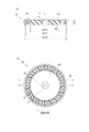
インペラ40は、PPS(ポリフェニレンサルファイド)樹脂で円板状に形成されている。図4に示すように、インペラ40の中心にはシャフト51が挿入されるD字状のシャフト穴41が形成されている。また、インペラ40は、複数の羽根42が周方向に配置された環状の昇圧部44を有している。複数の羽根42は、インペラ40の端面432、433に対して傾斜して形成されており、羽根42同士の空間に導入された燃料は、旋回流となって流れる過程で昇圧される。
The
インペラ40は、一方の端面432がカバー20の端面23に対向し、他方の端面433がケーシング30の底面33に対向しつつ回転する。回転中、燃料の圧力バランスが崩れると、インペラ40が軸に対して傾き、インペラ端面432とカバー端面23、又はインペラ端面433とケーシング底面33とが部分的に当接する可能性がある。
The
インペラ40の寸法例は次のとおりである。
昇圧部44の内側径φDi2≒24mm(≒φDc2≒φDk2)
昇圧部44の外側径φDi3≒30mm(≒φDc3≒φDk3)
インペラ40の外径φDi4≒34mm(≒φDk4)
インペラ40の厚さti ≒ 4mm(≒dk)
Examples of dimensions of the
Inner diameter of the
The outside diameter of the
以上のように構成された燃料ポンプ11、12、13は、モータ部50の電機子54と共にシャフト51が回転し、それに伴ってインペラ40が回転すると、吸入口24から吸入され導入流路26に導かれた燃料は、インペラ40の昇圧部44で昇圧され、導出流路36を経由して吐出流路39から流出する。そして、電機子54と永久磁石56との隙間を通り、燃料室63、連通路64、逆止弁部70を経由して吐出口65から燃料ポンプ11、12、13の外部へ吐出される。
In the fuel pumps 11, 12, and 13 configured as described above, when the
このような燃料ポンプにおいて、吐出流量に対して障害となる種々の要因がある。そのうち吸入側における要因の一つである負圧の影響について図5を参照して説明する。
図5に示すように、吸入口24からインペラ40に向かって流入する燃料流Fの流速が急に速くなる部分では、ベンチュリー効果によって発生する負圧Vcが燃料の流れを妨げる可能性が推定される。そこで、吸入口24から導入流路26に接続する部分の形状は、なるべく負圧が発生しにくいように形成されている。
In such a fuel pump, there are various factors that hinder the discharge flow rate. The influence of negative pressure, which is one of the factors on the suction side, will be described with reference to FIG.
As shown in FIG. 5, in the portion where the flow velocity of the fuel flow F flowing from the
また、エンジンや周辺装置等からの伝熱によって燃料温度が上昇すると、燃料中の揮発成分が気化し、ベーパとして流路内に滞留する場合がある。それにより、インペラ40がベーパを噛み込みながら回転するため、流量が低下するという問題が生じる。そこで本発明では、吸入口24と導入流路26との流路空間が重なり合う吸入接続部25の開口面積を拡大することで、ベーパの発生による流量低下を抑制することを特徴とする。
Further, when the fuel temperature rises due to heat transfer from the engine, peripheral devices, or the like, volatile components in the fuel may be vaporized and stay in the flow path as vapor. Thereby, since the
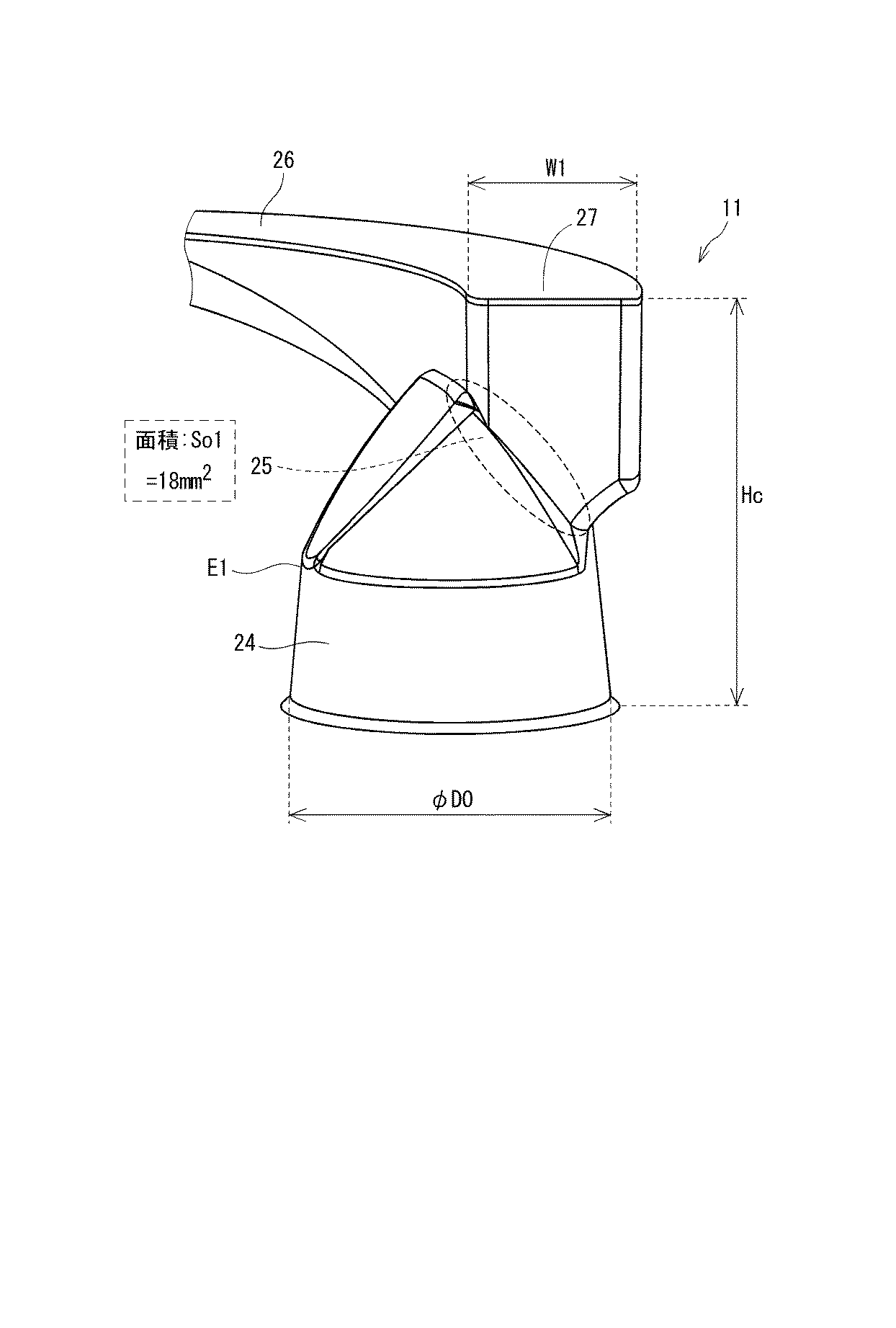
上述の基本構成を共通としつつ吸入接続部25の形状のみを変更した3通りの燃料ポンプの評価品No.1、No.2、No.3を製作し、流量性能を比較した。評価品No.1、2、3は、それぞれ「燃料ポンプ11」、「燃料ポンプ12」、「燃料ポンプ13」に対応する。評価品No.1、2、3の吸入接続部25の「流路空間」を三次元モデルで表した模式図を、図6、7、8に示す。
Three types of fuel pump evaluation products No. 1 having the same basic configuration as described above, but having only the shape of the
図6、7、8の上下方向における吸入口24の開口位置から導入流路26の上端までの距離Hcはカバー20の高さに相当する。このカバー20の高さHc、吸入口24の口元径φD0、及び、導入流路26の中間部より下流の図示しない部分の幅や高さは、評価品No.1、2、3において同一とする。
6, 7, and 8, the distance Hc from the opening position of the
図6に示す評価品No.1(燃料ポンプ11)は、吸入口24の高さの半分に達しない位置に勾配が変化する角部E1が形成されている。そのため、吸入口24の角部E1より底側の部分で、流路断面積が急激に減少している。そして、流路断面積が減少する部分で吸入口24と導入流路26とが接続し、吸入接続部25を形成している。この形態による吸入接続部25の開口面積So1は約18mm2である。
Evaluation product No. shown in FIG. 1 (fuel pump 11) has a corner E1 where the gradient changes at a position that does not reach half the height of the
図7に示す評価品No.2(燃料ポンプ12)は、吸入口24の角部E2が底の近傍に形成され、口元から角部E2まで、内径勾配が比較的緩いほぼ一定の角度となっている。そのため、吸入口24の深さ方向の流路断面積の減少は比較的小さい。そして、吸入口24の底から約3分の1〜約2分の1の範囲で吸入接続部25が形成されている。導入流路26の始端部27の幅W2は評価品No.1の始端部27の幅W1と同等である。この形態による吸入接続部25の開口面積So2は約22mm2である。
Evaluation product No. 1 shown in FIG. 2 (fuel pump 12), the corner E2 of the
図8に示す評価品No.3(燃料ポンプ13)は、角部E3の位置を含む吸入口24の形態は評価品No.2と同様である。また、導入流路26の始端部27の幅W3は、評価品No.2の幅W2よりも大きく形成されている。つまり、吸入口24と導入流路26とは、吸入口24の径方向において、評価品No.1、No.2よりも広い範囲で接続している。この形態による吸入接続部25の開口面積So3は約27mm2である。
Evaluation product No. shown in FIG. 3 (fuel pump 13), the shape of the
また、図2におけるカバー端面23のシール長さLsは、評価品No.1、No.2で約6.4mmであり、始端部27の幅W3を大きくした評価品No.3では約5.0mmである。
Further, the seal length Ls of the
以上の評価品No.1、2、3について、第1の評価として「吸入燃料中にベーパが発生することによる流量低下率」を評価し、第2の評価として「カバー20の端面23が摩耗することによる流量低下率」を評価した。
この評価の結果、第1の評価及び第2の評価の要件をいずれも満足する燃料ポンプは、「請求項1に係る発明を実施するための形態」に該当する。
The above evaluation product No. As for the first, second, and third evaluations, the first evaluation is “flow rate reduction rate due to vapor generation in intake fuel”, and the second evaluation is “flow rate reduction rate due to wear of end face 23 of
As a result of this evaluation , the fuel pump that satisfies both the requirements of the first evaluation and the second evaluation corresponds to the “embodiment for carrying out the invention according to
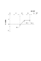
第1の評価では、想定される最高温時を反映した60℃の恒温槽内で燃料ポンプ11、12、13を所定の回転数で作動させた。燃料ポンプ11、12、13内でベーパが発生するにつれ、流量は、初期に対してあるレベルまで低下した。このときの初期流量に対する、初期流量と最小流量との差(低下流量)の割合を流量低下率として求めた。
第1の評価の結果を表1及び図9に示す。
In the first evaluation, the fuel pumps 11, 12, and 13 were operated at a predetermined number of revolutions in a 60 ° C. thermostat reflecting the assumed maximum temperature. As vapor was generated in the fuel pumps 11, 12, 13, the flow rate decreased to a certain level with respect to the initial stage. The ratio of the difference between the initial flow rate and the minimum flow rate (decrease flow rate) with respect to the initial flow rate at this time was determined as the flow rate reduction rate.
The results of the first evaluation are shown in Table 1 and FIG.
ここで、流量低下率に対する要求仕様を「20%未満」とした。本実施形態では、燃料ポンプの初期流量は、車両の通常走行時に想定される流量に対して25%以上の余裕をみて設定されている。また、初期流量の要求仕様の設定にあたり、この程度の余裕をみることは、当該技術分野の技術常識である。したがって、仮に初期流量から20%以内で流量が低下したとしても、車両の通常走行に直ちに重大な影響を及ぼすことはないと考えられる。一方、初期流量から20%以上流量が低下した場合には、エンジンへ供給される燃料が不足し、好適な走行ができなくなるおそれがある。なお、さらに信頼性を向上する見地から、流量低下率に対する要求仕様を「15%未満」としてもよい。 Here, the required specification for the flow rate reduction rate was “less than 20%”. In this embodiment, the initial flow rate of the fuel pump is set with a margin of 25% or more with respect to the flow rate assumed during normal driving of the vehicle. Moreover, it is common technical knowledge in the technical field to allow such a margin when setting the required specification of the initial flow rate. Therefore, even if the flow rate falls within 20% from the initial flow rate, it is considered that there is no immediate significant influence on the normal running of the vehicle. On the other hand, when the flow rate is reduced by 20% or more from the initial flow rate, the fuel supplied to the engine is insufficient, and there is a possibility that suitable running cannot be performed. In addition, from the viewpoint of further improving the reliability, the required specification for the flow rate reduction rate may be “less than 15%”.
このような前提の下、開口面積が18mm2であるNo.1では流量低下率が22%であるため、要求仕様を満足しない。それに対し、開口面積が22mm2であるNo.2、27mm2であるNo.3は流量低下率が13%であるため、20%未満又は15%未満のいずれの要求仕様も満足する。この結果から、開口面積が22mm2以上であれば、高温時のベーパ発生に対して流量低下を抑制することができると考えられる。 Under such a premise, No. 1 having an opening area of 18 mm 2 is used. 1, the flow rate reduction rate is 22%, so the required specifications are not satisfied. On the other hand, No. having an opening area of 22 mm 2 . 2 , 27 mm 2 No. Since No. 3 has a flow rate reduction rate of 13%, it satisfies any required specification of less than 20% or less than 15%. From this result, it is considered that when the opening area is 22 mm 2 or more, the flow rate can be suppressed from being reduced due to vapor generation at high temperature.
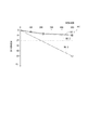
次に第2の評価では、所定の異物を混入した燃料を用いて500Hrの作動耐久を行った。PPS製のインペラ40がアルミニウム製のカバー20の端面23にある押付力で押し付けられたとき、インペラ40とカバー20との間に介在する異物によってカバー端面23が摩耗することが予測される。カバー端面23が摩耗すると、吸入した燃料の一部が導入流路26から漏れ、圧送効率が低下するため流量が低下するという仮説の下、流量の低下率を経時的に評価した。
第2の評価の結果を表2及び図10に示す。
Next, in the second evaluation, an operation durability of 500 hours was performed using a fuel mixed with predetermined foreign matters. When the
The results of the second evaluation are shown in Table 2 and FIG.
カバー端面23の摩耗後の流量低下率に対する要求仕様は、第1の評価と同じ「20%未満」を基準とした。なお、この場合も、さらに信頼性を向上する見地から、流量低下率に対する要求仕様を「15%未満」としてもよい。
The required specification for the rate of decrease in the flow rate after wear of the
500Hrの作動耐久の結果、シール長さLsが6.4mmであるNo.1、No.2では流量低下率が約10%であったのに対し、シール長さLsが5.0mmであるNo.3では流量低下率が約50%に及んだ。これは、No.3のように吸入接続部25の開口面積Soを大きくしようとして導入流路26の幅Wを広くし過ぎると、シール長さLsが不足し、インペラ40に作用する圧力バランスが崩れ、インペラ40がカバー20に押し付けられる力によってカバー端面23の摩耗が大きくなるからであると考えられる。
この結果から、摩耗による流量低下を20%未満又は15%未満とするためには、シール長さLsを6.4mm以上確保する必要があると考えられる。
As a result of the operation durability of 500 hours, the seal length Ls is 6.4 mm. 1, no. In No. 2, the flow rate reduction rate was about 10%, whereas the seal length Ls was 5.0 mm. In No. 3, the flow rate reduction rate reached about 50%. This is no. If the width W of the
From this result, it is considered necessary to secure the seal length Ls of 6.4 mm or more in order to reduce the flow rate due to wear to less than 20% or less than 15%.
以上より、評価品No.2としての燃料ポンプ12は、第1の評価及び第2の評価の要件を共に満足する。すなわち、燃料ポンプ12は、請求項1に係る発明を実施するための形態であることから、本発明の第1実施形態と位置づける。
また、評価品No.3としての燃料ポンプ13は、第1の評価の要件を満足し、第2の評価の要件を満足しない。燃料ポンプ13は、参考形態としての第2実施形態と位置づける。
他方、第1の評価の要件を満足しない評価品No.1としての燃料ポンプ11は、燃料ポンプ12、13と対比するための比較例に該当する。
As described above, the evaluation product No. The
In addition, the evaluation product No. The
On the other hand, an evaluation product No. that does not satisfy the requirements of the first evaluation. The
(効果)
本発明の実施形態による燃料ポンプの効果は次のとおりである。
(1)第1実施形態の燃料ポンプ12、及び、第2実施形態の燃料ポンプ13は、吸入接続部25の開口面積を22mm2以上とすることで、高温時に発生するベーパの滞留を防ぐことができ、ベーパによる流量低下を抑制することができる。よって、燃料ポンプが適用されるシステムにおいて要求流量の増大に応えることができる。
(effect)
The effects of the fuel pump according to the embodiment of the present invention are as follows.
(1) The
(2)第1実施形態の燃料ポンプ12は、さらに、カバー端面23におけるシール長さLsを6.4mm以上とすることで、圧力バランスの崩れたインペラ40がカバー20に押し付けられたとき、インペラ40とカバー20との間に介在する異物によって生ずるカバー端面23の摩耗を抑制し、この摩耗に起因する流量低下を抑制することができる。
(2) The
上記の説明において例示した寸法や材質は実施形態としての一例に過ぎず、他の実施形態では、本発明の技術的思想に準じて、適当な寸法や材質を設定してよい。
本発明の燃料ポンプは、モータ部50と一体に構成されるものに限らず、別体の回転駆動源からシャフトを介してインペラが回転駆動される独立した態様の燃料ポンプであってもよい。吐出口には逆止弁部が設けられなくてもよい。また、車両に適用されるものに限らず、他の用途に適用されるものであってもよい。
本発明は、上述した実施形態に限定されるものではなく、発明の趣旨を逸脱しない範囲で種々の形態で実施可能である。
The dimensions and materials exemplified in the above description are merely examples as embodiments, and in other embodiments, appropriate dimensions and materials may be set according to the technical idea of the present invention.
The fuel pump according to the present invention is not limited to being configured integrally with the
The present invention is not limited to the embodiments described above, and can be implemented in various forms without departing from the spirit of the invention.
12、13・・・燃料ポンプ、
20・・・カバー、 21・・・中央凹部、 23・・・端面、
24・・・吸入口 、 25・・・吸入接続部、
26・・・導入流路、 27・・・始端部、 28・・・終端部、
30・・・ケーシング、 39・・・吐出流路、
40・・・インペラ、 42・・・羽根、 44・・・昇圧部、
50・・・モータ部(回転駆動源)、 51・・・シャフト、
So・・・開口面積、
Ls・・・シール長さ。
12, 13 ... Fuel pump,
20 ... cover, 21 ... central recess, 23 ... end face,
24 ... suction port, 25 ... suction connection part,
26 ... Introduction flow path, 27 ... Start end, 28 ... Termination,
30 ... casing, 39 ... discharge flow path,
40 ... impeller, 42 ... vane, 44 ... booster,
50: Motor part (rotation drive source), 51: Shaft,
So ... opening area,
Ls: Seal length.
Claims (3)
前記シャフトに固定され、複数の羽根(42)が周方向に配置された環状の昇圧部(44)を有するインペラ(40)と、
前記インペラの軸方向の一方側に設けられ、燃料が吸入される吸入口(24)、及び、前記吸入口に連通する始端部(27)から周方向の他端である終端部(28)に向かって前記インペラの前記昇圧部に沿って溝状に形成された導入流路(26)を有するカバー(20)と、
前記インペラの軸方向の他方側に設けられ、昇圧された燃料が流出する吐出流路(39)を有するケーシング(30)と、
を備え、前記インペラの回転によって、吸入した燃料を圧送する燃料ポンプ(12、13)であって、
前記カバーの前記吸入口と前記導入流路との流路空間が重なり合う吸入接続部(25)の開口面積(So)は、燃料中に発生するベーパによる流量低下率が20%未満となるように所定の面積以上に設定されており、
前記カバーの中心軸と前記吸入口とを結ぶ径方向における凹部(21)の外縁から前記導入流路の内縁までの長さであるシール長さ(Ls)は、前記インペラと前記カバーとの間に介在する異物によって生ずる前記カバーの端面の摩耗による流量低下率が20%未満となるように所定の長さ以上に設定されていることを特徴とする燃料ポンプ。 A shaft (51) rotated by the driving force of the rotational drive source (50);
An impeller (40) fixed to the shaft, and having an annular pressure-up part (44) in which a plurality of blades (42) are arranged in the circumferential direction;
Provided on one side in the axial direction of the impeller, from a suction port (24) through which fuel is sucked, and from a start end portion (27) communicating with the suction port to a terminal end portion (28) which is the other end in the circumferential direction A cover (20) having an introduction flow path (26) formed in a groove shape along the pressure increasing portion of the impeller,
A casing (30) provided on the other side of the impeller in the axial direction and having a discharge passage (39) through which pressurized fuel flows out;
A fuel pump (12, 13) that pumps inhaled fuel by rotation of the impeller,
The opening area (So) of the suction connection part (25) where the flow path space between the suction port of the cover and the introduction flow path overlaps is such that the flow rate reduction rate due to vapor generated in the fuel is less than 20%. It is set to a predetermined area or more ,
The seal length (Ls), which is the length from the outer edge of the recess (21) in the radial direction connecting the central axis of the cover and the suction port to the inner edge of the introduction flow path, is between the impeller and the cover. A fuel pump, characterized in that it is set to a predetermined length or more so that the rate of flow reduction due to wear of the end face of the cover caused by foreign matter present in the cover is less than 20% .
Priority Applications (1)
| Application Number | Priority Date | Filing Date | Title |
|---|---|---|---|
| JP2013131731A JP6182997B2 (en) | 2013-06-24 | 2013-06-24 | Fuel pump |
Applications Claiming Priority (1)
| Application Number | Priority Date | Filing Date | Title |
|---|---|---|---|
| JP2013131731A JP6182997B2 (en) | 2013-06-24 | 2013-06-24 | Fuel pump |
Publications (2)
| Publication Number | Publication Date |
|---|---|
| JP2015004354A JP2015004354A (en) | 2015-01-08 |
| JP6182997B2 true JP6182997B2 (en) | 2017-08-23 |
Family
ID=52300437
Family Applications (1)
| Application Number | Title | Priority Date | Filing Date |
|---|---|---|---|
| JP2013131731A Active JP6182997B2 (en) | 2013-06-24 | 2013-06-24 | Fuel pump |
Country Status (1)
| Country | Link |
|---|---|
| JP (1) | JP6182997B2 (en) |
Family Cites Families (3)
| Publication number | Priority date | Publication date | Assignee | Title |
|---|---|---|---|---|
| JP3907887B2 (en) * | 1999-10-28 | 2007-04-18 | 株式会社エンプラス | Impeller for circumferential flow pump |
| JP4600714B2 (en) * | 2001-03-19 | 2010-12-15 | 株式会社デンソー | Fuel pump |
| WO2006028243A1 (en) * | 2004-09-08 | 2006-03-16 | Mitsuba Corporation | Fuel pump |
-
2013
- 2013-06-24 JP JP2013131731A patent/JP6182997B2/en active Active
Also Published As
| Publication number | Publication date |
|---|---|
| JP2015004354A (en) | 2015-01-08 |
Similar Documents
| Publication | Publication Date | Title |
|---|---|---|
| JP4623217B2 (en) | Fuel supply pump | |
| JP5602950B2 (en) | Side channel blowers, especially secondary air blowers used in internal combustion engines | |
| US20150349594A1 (en) | Electric Pump | |
| JP2007023784A (en) | Fuel pump | |
| JP4811496B2 (en) | Fuel pump | |
| JP4396750B2 (en) | Fuel pump | |
| JP2010220271A (en) | Electric motor | |
| JP5772720B2 (en) | pump | |
| JP6182997B2 (en) | Fuel pump | |
| TWI464321B (en) | Fuel pump | |
| TW472111B (en) | Electric fuel pump | |
| CN101509448A (en) | Regenerative fuel pump | |
| KR100904601B1 (en) | Fuel pump and fuel feed apparatus having the same | |
| JPH03199693A (en) | Circular flow type liquid pump | |
| JP5747862B2 (en) | Fuel pump | |
| JP2008101469A (en) | Fuel pump | |
| KR101222017B1 (en) | Impeller of fuel pump for vehicle | |
| JP5207999B2 (en) | Fuel pump | |
| JP2010138704A (en) | Pressure regulator and fuel supply device | |
| JPH06272685A (en) | Motor-driven fuel pump | |
| JP5059679B2 (en) | Pump structure | |
| US7950898B2 (en) | Fuel pump having impeller | |
| US20060067811A1 (en) | Impeller with an abradable tip | |
| CN108930619A (en) | Fuel supply system | |
| JPS58119959A (en) | Motor type fuel pump |
Legal Events
| Date | Code | Title | Description |
|---|---|---|---|
| A621 | Written request for application examination |
Free format text: JAPANESE INTERMEDIATE CODE: A621 Effective date: 20160526 |
|
| A977 | Report on retrieval |
Free format text: JAPANESE INTERMEDIATE CODE: A971007 Effective date: 20170223 |
|
| A131 | Notification of reasons for refusal |
Free format text: JAPANESE INTERMEDIATE CODE: A131 Effective date: 20170228 |
|
| A521 | Request for written amendment filed |
Free format text: JAPANESE INTERMEDIATE CODE: A523 Effective date: 20170411 |
|
| TRDD | Decision of grant or rejection written | ||
| A01 | Written decision to grant a patent or to grant a registration (utility model) |
Free format text: JAPANESE INTERMEDIATE CODE: A01 Effective date: 20170627 |
|
| A61 | First payment of annual fees (during grant procedure) |
Free format text: JAPANESE INTERMEDIATE CODE: A61 Effective date: 20170710 |
|
| R151 | Written notification of patent or utility model registration |
Ref document number: 6182997 Country of ref document: JP Free format text: JAPANESE INTERMEDIATE CODE: R151 |
|
| R250 | Receipt of annual fees |
Free format text: JAPANESE INTERMEDIATE CODE: R250 |
|
| R250 | Receipt of annual fees |
Free format text: JAPANESE INTERMEDIATE CODE: R250 |
|
| R250 | Receipt of annual fees |
Free format text: JAPANESE INTERMEDIATE CODE: R250 |
|
| S111 | Request for change of ownership or part of ownership |
Free format text: JAPANESE INTERMEDIATE CODE: R313113 |
|
| R350 | Written notification of registration of transfer |
Free format text: JAPANESE INTERMEDIATE CODE: R350 |
|
| R250 | Receipt of annual fees |
Free format text: JAPANESE INTERMEDIATE CODE: R250 |