JP6182829B2 - Manufacturing method of shaft for golf club - Google Patents
Manufacturing method of shaft for golf club Download PDFInfo
- Publication number
- JP6182829B2 JP6182829B2 JP2012122093A JP2012122093A JP6182829B2 JP 6182829 B2 JP6182829 B2 JP 6182829B2 JP 2012122093 A JP2012122093 A JP 2012122093A JP 2012122093 A JP2012122093 A JP 2012122093A JP 6182829 B2 JP6182829 B2 JP 6182829B2
- Authority
- JP
- Japan
- Prior art keywords
- shaft
- golf club
- switching point
- mandrel
- taper
- Prior art date
- Legal status (The legal status is an assumption and is not a legal conclusion. Google has not performed a legal analysis and makes no representation as to the accuracy of the status listed.)
- Active
Links
Images


Landscapes
- Golf Clubs (AREA)
Description
本発明は、ゴルフクラブ用シャフトの製造方法に関する。 The present invention relates to a method for manufacturing a shaft for a golf club.
ゴルフのスコアを良くするためには、飛距離を向上させることが重要である。特に距離の長いホールにおいて、第一打目の飛距離が向上すれば、二打目以降の距離が短くなり精度の高めることが可能となるので、スコア向上に繋げることが可能となる。 In order to improve the golf score, it is important to improve the flight distance. In particular, in a hole with a long distance, if the flight distance of the first shot is improved, the distance after the second shot can be shortened and the accuracy can be improved, which can lead to an improvement in score.
ゴルフにおいて、打球の飛距離は、ボールの初速、打ち出し角度、スピン量で決定することが知られている。ボールの初速、打ち出し角度、スピン量は、ゴルフヘッドの特性にも依存するが、これら3つの要素については、ボールを打撃する瞬間のシャフトの動き(変形)も大きな影響を与える。特にシャフトの曲げ剛性分布がこれらの要素に大きく影響するため、様々な曲げ剛性分布を有するシャフトが開発されている。中でも強化繊維を使用した繊維強化プラスチック製ゴルフクラブ用シャフトは、この曲げ剛性分布の調整がし易いため、近年ではウッド用のゴルフクラブ用シャフトの多くに繊維強化プラスチックが用いられている。 In golf, it is known that the flight distance of a hit ball is determined by the initial velocity, launch angle, and spin amount of the ball. Although the initial velocity, launch angle, and spin amount of the ball depend on the characteristics of the golf head, the movement (deformation) of the shaft at the moment of hitting the ball has a great influence on these three factors. In particular, since the bending stiffness distribution of the shaft greatly affects these factors, shafts having various bending stiffness distributions have been developed. Among them, fiber reinforced plastic golf club shafts using reinforced fibers are easy to adjust the bending stiffness distribution, and in recent years, fiber reinforced plastics are used in many wood golf club shafts.
シャフトの動き(変形)に対する曲げ剛性分布の影響は、硬さ(フレックス)によるものと、曲げ剛性分布曲線の傾きであることが知られている。硬さ(フレックス)による影響は、硬ければシャフトの動き(変形)が小さくなり、軟らかければシャフトの動き(変形)が大きくなるため、力のある人は硬いシャフトを、力の無い人は軟らかいシャフトを選ぶことになる。これに対し、剛性分布曲線の傾きの影響は、傾きが大きいほどシャフトがしなって元に戻る復元力が大きく、傾きが小さいほどシャフトがしなって元に戻る復元力が小さくなる。よって、剛性分布曲線の傾きが大きいほどしなり戻りが速いので、スイングテンポの速い人やヘッドスピードの速い人に適し、剛性分布曲線の傾きが小さいほどしなり戻りが遅いので、スイングテンポが遅い人やヘッドスピードの遅い人に適している。 It is known that the influence of the bending stiffness distribution on the movement (deformation) of the shaft is due to the hardness (flex) and the inclination of the bending stiffness distribution curve. The effect of hardness (flex) is that the movement (deformation) of the shaft will be smaller if it is hard, and the movement (deformation) of the shaft will be larger if it is soft. Choose a soft shaft. On the other hand, the influence of the inclination of the stiffness distribution curve is such that the greater the inclination, the greater the restoring force to return to the original state, and the smaller the inclination, the smaller the restoring force to return to the original state. Therefore, the higher the slope of the stiffness distribution curve, the faster the return, so it is suitable for people with fast swing tempos and fast head speeds. The smaller the slope of the stiffness distribution curve, the slower the return, so the swing tempo is slow. Suitable for people and people with slow head speeds.
ゴルフクラブ用シャフトにおける曲げ剛性分布とシャフトの動き(変形)の関係を考える場合、下記のように3つの部位に分割出来ると考えられる。 When considering the relationship between the bending stiffness distribution in the golf club shaft and the movement (deformation) of the shaft, it is considered that the golf club shaft can be divided into three parts as follows.
A)細径端部〜細径端300mm
B)細径端350mm〜細径端800mm
C)細径端850mm〜太径端部
A)については、ヘッド装着部位に相当し、打ち出し角度やスピン量に影響を与える部位である。以下、この部位を「シャフト先端部」と呼ぶ。この部位はシャフトの外径変位が小さいため、曲げ剛性分布曲線の傾きは小さく、硬さがシャフトの性能に与える影響が多い部位である。
A) Small diameter end to small diameter end 300mm
B) Narrow end 350mm-Narrow end 800mm
C) The
B)については、シャフトの中央部であり、スイング中のシャフトの変形量が最も大きく、ヘッドスピードに影響を与える部位である。以下、この部位を「シャフト中央部」と呼ぶ。この部位はシャフトの外径変位が大きいため、曲げ剛性分布曲線の傾きが大きく、曲げ剛性分布曲線がシャフトの性能に与える影響が多い部位である。 About B), it is a central part of the shaft, which is the part where the amount of deformation of the shaft during the swing is the largest and affects the head speed. Hereinafter, this portion is referred to as “shaft central portion”. Since this portion has a large outer diameter displacement of the shaft, the inclination of the bending stiffness distribution curve is large, and the bending stiffness distribution curve has a great influence on the performance of the shaft.
C)については、グリップ装着部位に相当し、以下、この部位を「グリップ部」と呼ぶ。この部位はシャフトの外径変位が小さいため、曲げ剛性分布曲線の傾きは小さく、硬さがシャフトの性能に与える影響が多い部位である。 C) corresponds to a grip mounting portion, and this portion is hereinafter referred to as a “grip portion”. Since this part has a small outer diameter displacement of the shaft, the inclination of the bending stiffness distribution curve is small, and the hardness has a great influence on the performance of the shaft.
ここで、ゴルフクラブ用シャフトの曲げ剛性E・Iは、下記式(1)より算出することが出来る。 Here, the bending rigidity E · I of the golf club shaft can be calculated from the following equation (1).
<式1>
I:断面二次モーメント
D:ゴルフクラブ用シャフトの外径
d:ゴルフクラブ用シャフトの内径
以上のことから、ゴルフクラブ用シャフトの曲げ剛性分布曲線は、シャフト外径の4乗に比例することになる。つまり、一般的なゴルフクラブ用シャフトにおいて、外径のテーパーがほぼ均一であることが多いことから、シャフト中央部の曲げ剛性分布曲線の傾きは、シャフト先端部に近いほど小さく、グリップ部に近いほど大きくなっている。
<
From the above, the bending stiffness distribution curve of the golf club shaft is proportional to the fourth power of the shaft outer diameter. That is, in general golf club shafts, the taper of the outer diameter is often substantially uniform, so the inclination of the bending stiffness distribution curve at the center of the shaft is smaller as it is closer to the shaft tip and closer to the grip. It is getting bigger.
ゴルフクラブ用シャフトの変形は、スイングの始動時は、グリップ側が大きくしなり、インパクトに向かってシャフトのしなりがシャフト先端部へ伝わることでヘッドへエネルギーを伝達し、ボールを飛ばすことになるが、上記の通り、一般的なゴルフクラブ用シャフトでは、シャフト中央部の曲げ剛性分布曲線の傾きがシャフト先端部に近いほど小さくなっていくため、インパクト直前においてシャフトのしなり戻りが遅くなるため、ヘッドスピードが上がり難い構造となっている。 As for the deformation of the golf club shaft, when the swing is started, the grip side becomes large, and the bending of the shaft is transmitted to the tip of the shaft toward the impact, thereby transmitting energy to the head and flying the ball. As described above, in a general golf club shaft, the inclination of the bending stiffness distribution curve at the center of the shaft becomes smaller as it approaches the tip of the shaft. The head speed is difficult to increase.
特許文献1では、ヘッドスピードに応じてグリップ部付近の曲げ剛性分布曲線の傾きとシャフト中央部の曲げ剛性分布曲線の傾きの比率を調整することでヘッドスピードに対応したゴルフクラブ用シャフトを得られるとしている。
In
しかしながら、特許文献1では、シャフト中央部の曲げ剛性分布が従来と同様に曲線状になってしまうため、ヘッドスピードに応じたフィーリングの向上は期待出来るが、飛距離の向上を望むことが出来ない。
However, in
また、特許文献2では、シャフト中央部に中間補強層を設け、シャフト中央部の曲げ剛性を高くすることで、シャフト中央部の曲げ剛性分布曲線をシャフト先端部に近いほど大きく、グリップ部に近いほど小さくしている。
Further, in
しかしながら、特許文献2では、シャフト中央部の曲げ剛性分布曲線の傾きが、シャフト先端部に近いほど大きくなるため、インパクト直前のシャフトのしなり戻りが速くなり、ヘッドの加速度は大きくなるが、スイング中のシャフトのしなり戻りが遅く、結果的にヘッドスピードが上がらず飛距離の向上を望むことが出来ない。
However, in
これらに対し、特許文献3では、シャフト中央部の曲げ剛性分布曲線が概ね直線状にすることで、万人に好まれる曲げ剛性分布を有するゴルフシャフトが得られるとしている。
On the other hand,
しかしながら、上述の通り、ゴルフクラブ用シャフトの曲げ剛性分布曲線は、シャフト外径の4乗に比例することになるため、特許文献3に例示されている実施例では、精度良くシャフト中央部の曲げ剛性分布を直線状にすることは出来ず、万人に好まれる曲げ剛性分布を有するゴルフシャフトを得ることが出来ない。
However, as described above, the bending stiffness distribution curve of the golf club shaft is proportional to the fourth power of the outer diameter of the shaft. Therefore, in the example illustrated in
本発明は、上記事情に鑑みてなされたものであって、スイング中のゴルフシャフトのしなり戻りの復元性を高めると同時にヘッドスピードを向上させ、飛距離を向上させるゴルフクラブ用シャフトを得ることを目的とする。 The present invention has been made in view of the above circumstances, and it is possible to obtain a golf club shaft which improves the head speed and improves the flight distance at the same time as improving the resilience of bending and returning of the golf shaft during a swing. With the goal.
上記の課題を達成するために、本発明は以下の構成を採用した。 In order to achieve the above object, the present invention employs the following configuration.
(1)強化繊維に樹脂を含浸してなるプリプレグをマンドレルに巻回して成るゴルフクラブ用シャフトの製造方法であって、
前記ゴルフクラブ用シャフトの細径端部より370mmから770mmの領域における50mmごとの距離L(mm)と、前記距離Lの位置における曲げ剛性EIL(×106kgf・mm2)とからなる曲げ剛性群(L,EIL)を(x,y)とし、該(x,y)を最小二乗法により下記式(A)に直線回帰した場合に、下記式(A)の相関係数の二乗R1 2が0.999以上であることを特徴とし、
y=−a1x+b1・・・式(A)
前記ゴルフクラブ用シャフトの細径端部より370mmから770mmの領域におけるゴルフクラブ用シャフトのテーパーが、細径端部側から少なくとも3段階にわたって漸次減少することを特徴とし、
成型されるゴルフクラブ用シャフトの細径端部より370mmから770mmの領域におけるテーパーが、細径端部側から少なくとも3段階にわたって漸次減少するよう、テーパー度が複数段に亘り漸次減少しているマンドレルを使用して成型することを特徴とするゴルフクラブ用シャフトの製造方法。
(1) A method for producing a shaft for a golf club formed by winding a prepreg obtained by impregnating a reinforcing fiber with a resin around a mandrel,
Bending the distance of each 50mm from 370mm from the small diameter end of the golf club shaft in the region of 770 mm L (mm), Naru Kara flexural rigidity EI L and (× 10 6 kgf · mm 2 ) at the position of the distance L When the stiffness group (L, EI L ) is (x, y) and the (x, y) is linearly regressed to the following formula (A) by the least square method, the square of the correlation coefficient of the following formula (A) R 1 2 is characterized in that 0.999 or more,
y = -a 1 x + b 1 Formula (A)
The taper of the golf club shaft in a region of 370 mm to 770 mm from the narrow diameter end portion of the golf club shaft is gradually reduced in at least three stages from the narrow diameter end side,
The mandrel in which the taper degree gradually decreases over a plurality of stages so that the taper in the region of 370 mm to 770 mm from the narrow end of the golf club shaft to be molded gradually decreases over at least three stages from the narrow end side. A method for producing a shaft for a golf club, which is molded using
(2) 繊維強化樹脂が、炭素繊維強化樹脂である上記(1)に記載のゴルフクラブ用シャフト。 ( 2 ) The golf club shaft according to (1), wherein the fiber reinforced resin is a carbon fiber reinforced resin.
本発明のゴルフクラブ用シャフトによると、ボールの初速向上と最適なボールスピン量を得られるので、飛距離の向上に繋がる。 According to the golf club shaft of the present invention, it is possible to improve the initial velocity of the ball and obtain the optimum amount of ball spin, which leads to the improvement of the flight distance.
以下、本発明の最良の形態について詳細に説明する。
<シャフト>
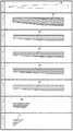
本発明に係る繊維強化樹脂を積層してなるゴルフクラブ用シャフトは、軸方向に垂直な面の外径が長さ方向の一端から他端に向かって大きくなり、途中の径切換部から他端まで外径が同一となるように形成されたものである。以下、外径が小さい側の端部を細径端部といい、外径が大きい側の端部を太径端部という。また、シャフトの長さ方向の径切換部から細径端部側を細径部、太径端部側を太径部という。 本発明のゴルフクラブ用シャフトは、例えば、図1のパターン1〜7に示すような裁断形状を有する繊維強化樹脂(プリプレグ)21〜27を、パターン1〜7の順番でマンドレル10に巻き付けて積層した後、加熱硬化した複数の繊維強化樹脂層で構成される。このゴルフクラブ用シャフトは、管状体主軸に対する強化繊維の巻角度が20〜75°の範囲内で、正逆両方向であるアングル層をともに有し、前記正逆2層のアングル層の巻き始め位置が実質的に半周分ずれたバイアス層が形成され、その外側に管状体主軸に対する強化繊維の巻角度が−5〜5°の範囲内であるストレート層を複数有している。
Hereinafter, the best mode of the present invention will be described in detail.
<Shaft>
In the golf club shaft formed by laminating the fiber reinforced resin according to the present invention, the outer diameter of the surface perpendicular to the axial direction increases from one end to the other end in the length direction, and the other end from the diameter switching portion in the middle It is formed so that the outer diameter is the same. Hereinafter, the end portion on the side having a smaller outer diameter is referred to as a small diameter end portion, and the end portion on the side having a large outer diameter is referred to as a large diameter end portion. Further, from the diameter switching portion in the longitudinal direction of the shaft, the small diameter end portion side is referred to as a thin diameter portion, and the large diameter end portion side is referred to as a large diameter portion. The golf club shaft of the present invention is laminated by winding fiber reinforced resins (prepreg) 21 to 27 having a cut shape as shown in
本発明のゴルフクラブ用シャフトは、ゴルフクラブ用シャフトの細径端部より370mmから770mmの領域における50mmごとの距離L(mm)と、前記距離Lの位置における曲げ剛性EIL(×106kgf・mm2)とからなる曲げ剛性群(L,EIL)を(x,y)とし、該(x,y)を最小二乗法により、下記式(A)に直線回帰した場合、下記式(A)の相関係数の二乗R1 2が0.999以上であることを満足するものである。 The golf club shaft of the present invention has a distance L (mm) every 50 mm in a region of 370 mm to 770 mm from the small diameter end portion of the golf club shaft, and a bending rigidity EI L (× 10 6 kgf) at the position of the distance L. When the bending stiffness group (L, EI L ) consisting of (mm 2 ) is (x, y) and the (x, y) is linearly regressed to the following formula (A) by the least square method, the following formula ( It is satisfied that the square R 1 2 of the correlation coefficient of A) is 0.999 or more.
y=−a1x+b1・・・(A)
式(A)の相関係数の二乗R1 2が0.999以上であると、シャフトの細径端部より370mmから770mmの領域における曲げ剛性分布が均一であり、斑がない。よって、この領域における曲げ剛性群が直線になることで、スイング中のシャフトのしなり戻りの復元性を高めると同時にヘッドスピードを向上させ、飛距離を向上させることが出来る。
ここで、式(A)は、シャフトのしなり戻りの速さに影響する関係式である。シャフトの曲げ剛性分布図は一般的に曲線形状となるため、個々のシャフトの曲げ剛性分布を比較することが難しい。そこで、式(A)のように、個々のシャフトの曲げ剛性分布を直線回帰することで、それぞれのシャフト特性の比較が容易になる。直線回帰した式(A)のa1は、シャフトのしなり戻りの速さを表している。a1が大きいほどシャフトのしなり戻りが速く、所謂「弾き感」の強いシャフトとなり、a1が小さいほどシャフトのしなり戻りが遅く、所謂「粘り感」の強いシャフトとなる。また、b1はシャフトの調子を表している。b1が大きいほどシャフト細径端側の曲げ剛性が高いので、所謂「手元調子」のシャフトとなり、b1が小さいほどシャフト細径端側の曲げ剛性が小さく、所謂「先調子」のシャフトとなる。
y = −a 1 x + b 1 (A)
When the square R 1 2 of the correlation coefficient of the formula (A) is 0.999 or more, the bending stiffness distribution in the region from 370 mm to 770 mm from the narrow diameter end of the shaft is uniform, and there are no spots. Therefore, since the bending rigidity group in this region is a straight line, it is possible to improve the restoring performance of the shaft returning during the swing, and at the same time to improve the head speed and the flight distance.
Here, the expression (A) is a relational expression that affects the speed at which the shaft is bent back. Since the bending stiffness distribution diagrams of shafts are generally curved, it is difficult to compare the bending stiffness distributions of individual shafts. Therefore, the linear characteristics of individual shafts are linearly regressed as in equation (A), thereby making it easy to compare the shaft characteristics. A 1 linear regression the formula (A) represents the bending speed of the return of the shaft. The larger the a 1, the faster the shaft will bend and return, and the shaft will have a strong “feeling of playing”, and the smaller the a 1 , the slower the shaft will return and the shaft will have a so-called “sticky” strength. B 1 represents the condition of the shaft. The larger the b 1, the higher the bending rigidity on the small diameter end side of the shaft, so that the shaft becomes a so-called “hand-tuned” shaft, and the smaller the b 1 , the smaller the bending rigidity on the small diameter end side. Become.
また、本発明のゴルフクラブ用シャフトは、細径端部より370mmから770mmの領域におけるゴルフクラブ用シャフトのテーパーが、細径端部側から少なくとも3段階にわたって漸次減少することを特徴とする。「ゴルフクラブ用シャフトのテーパーが、細径端部側から少なくとも3段階にわたって漸次減少する」とは、ゴルフクラブ用シャフトが少なくとも3つ以上の異なるテーパー領域を有し、その領域のテーパーは、細径端部側から太径部方向にいくほど小さくなっていることを意味する。各領域内におけるテーパーは一定でも連続的に若干変化してもよいが、設計のし易さから、通常は各領域内におけるテーパーは一定にする。「ゴルフクラブ用シャフトのテーパーが、細径端部側から少なくとも3段階にわたって漸次減少する」について、ゴルフクラブ用シャフトの細径端部より370mmから770mmの領域において3つの異なるテーパー領域を有する場合の例を挙げてより具体的に説明すると、各テーパー領域を細軽端部側から領域(1)、領域(2)、領域(3)とした場合、領域(1)のテーパー>領域(2)のテーパー>領域(3)のテーパーとなっていることを意味している。本領域におけるゴルフクラブ用シャフトのテーパーは、本来曲線になる曲げ剛性分布を精度良く直線に近似させるために、テーパーの変化は多い方が好ましいが、マンドレルの加工精度のコントロールや、巻き付けが難しくなってしまう。よって、実際の生産性を考慮すると、本領域におけるシャフトのテーパーの変化は、3段階、または4段階であることがより好ましい。 In addition, the golf club shaft of the present invention is characterized in that the taper of the golf club shaft in the region of 370 mm to 770 mm from the narrow end portion gradually decreases in at least three steps from the narrow end portion side. “The taper of the golf club shaft gradually decreases in at least three steps from the side of the small diameter end” means that the golf club shaft has at least three different tapered regions, and the taper of the region is narrow. It means that it becomes smaller as it goes from the diameter end side toward the large diameter part. The taper in each region may be constant or slightly change continuously, but usually the taper in each region is constant for ease of design. Regarding “the taper of the golf club shaft gradually decreases in at least three steps from the side of the small diameter end portion”, in the case of having three different taper areas in the region of 370 mm to 770 mm from the small diameter end portion of the golf club shaft More specifically, by way of example, when each tapered region is defined as the region (1), the region (2), and the region (3) from the thin end side, the taper of the region (1)> the region (2). It is meant that the taper is greater than the taper of region (3). The taper of the golf club shaft in this area is preferred to have a large change in taper in order to approximate the bending stiffness distribution, which is originally a curve, to a straight line with high accuracy, but it becomes difficult to control the mandrel processing accuracy and to wind it. End up. Therefore, in consideration of actual productivity, the change in the taper of the shaft in this region is more preferably three or four.
ゴルフシャフトの領域を3分割した場合、ヘッドを取り付ける側の「ヘッド装着部」と、グリップを取り付ける側の「グリップ部」と、それ以外の「シャフト中央部」に分割することが出来る。「ヘッド装着部」に相当するシャフト細径端から細径端300mmの領域の曲げ剛性は、ボールの打ち出し角度に大きく影響し、「グリップ部」に相当するシャフト細径端800mmから太径端の領域の曲げ剛性は、スイング始動時の“タメ”に大きく影響する。これら以外の所謂「シャフト中央部」は、スイング始動時に“タメ”によって作られたシャフトのしなりによるエネルギーを、ヘッドに伝達する上で重要な領域であり、今回の発明はこの領域、つまり上記の細径端部より370mmから770mmの領域の曲げ剛性分布に着目し、この領域の曲げ剛性分布を最適な形態とすることで、飛距離向上に繋がるシャフトを見出している。 When the region of the golf shaft is divided into three, it can be divided into a “head mounting portion” on the side where the head is attached, a “grip portion” on the side where the grip is attached, and the other “shaft central portion”. The bending rigidity in the region from the shaft small diameter end corresponding to the “head mounting portion” to the small diameter end 300 mm greatly affects the ball launch angle, and the shaft small diameter end corresponding to the “grip portion” from 800 mm to the large diameter end. The flexural rigidity of the region has a great influence on the “tick” at the start of the swing. The so-called “shaft central portion” other than these is an important region for transmitting the energy generated by the bending of the shaft created by “Tame” to the head at the time of starting the swing. Focusing on the bending stiffness distribution in the region of 370 mm to 770 mm from the small-diameter end of the shaft, and finding the shaft that leads to the improvement of the flight distance by making the bending stiffness distribution in this region optimal.
<繊維強化樹脂>
繊維強化樹脂に用いられる樹脂成分(本発明のゴルフクラブ用シャフトを構成するマトリックス樹脂)には、熱可塑性樹脂や熱硬化性樹脂を使用することができるが、好ましくは熱硬化性樹脂が用いられる。
<Fiber reinforced resin>
A thermoplastic resin or a thermosetting resin can be used as the resin component (matrix resin constituting the golf club shaft of the present invention) used for the fiber reinforced resin, but a thermosetting resin is preferably used. .
熱可塑性樹脂としては、ポリアミド系樹脂、ポリアクリレート系樹脂、ポリスチレン系樹脂、ポリエチレン系樹脂、およびこれらの混合樹脂を用いることができる。一方、熱硬化性樹脂としては、エポキシ系樹脂、不飽和ポリエステル系樹脂、フェノール系樹脂、ユリア系樹脂、メラミン系樹脂、ジアリルフタレート系樹脂、ウレタン系樹脂、ポリイミド系樹脂、およびこれらの混合樹脂を使用することができる。中でも、エポキシ系樹脂は硬化収縮率が少なく、高い剛性と靭性値を有するので、最も好ましく使用される。 As the thermoplastic resin, polyamide resins, polyacrylate resins, polystyrene resins, polyethylene resins, and mixed resins thereof can be used. On the other hand, as thermosetting resins, epoxy resins, unsaturated polyester resins, phenol resins, urea resins, melamine resins, diallyl phthalate resins, urethane resins, polyimide resins, and mixed resins thereof are used. Can be used. Among these, epoxy resins are most preferably used because they have a low cure shrinkage and high rigidity and toughness.
また、繊維強化樹脂に用いられる繊維(本発明のゴルフクラブ用シャフトを構成する繊維)としては、金属繊維、ボロン繊維、炭素繊維、ガラス繊維、セラミクス繊維などの無機系繊維、アラミド繊維、その他の高強力合成繊維などを使用することができる。無機繊維は軽量、かつ高強力であることから好ましく使用される。中でも、炭素繊維が、比強度、比剛性に優れるので最適である。 Further, the fibers used for the fiber reinforced resin (fibers constituting the golf club shaft of the present invention) include inorganic fibers such as metal fibers, boron fibers, carbon fibers, glass fibers, ceramic fibers, aramid fibers, and the like. High-strength synthetic fibers can be used. Inorganic fibers are preferably used because of their light weight and high strength. Among these, carbon fiber is optimal because it is excellent in specific strength and specific rigidity.
これらの繊維は、単独または混合して使用できる。また、長繊維、短繊維、およびこれらの混合繊維など、どのような長さの繊維を用いてもよい。 These fibers can be used alone or in combination. Further, any length of fibers such as long fibers, short fibers, and mixed fibers thereof may be used.
<シャフトの製造方法>
本発明のゴルフ用シャフトを製造するためには、成型されるゴルフクラブ用シャフトの細径端部より370mmから770mmの領域におけるテーパーが、少なくとも3段階にわたって漸次減少するよう、テーパー度が複数段に亘り、漸次減少しているマンドレルを適宜選択することで、本発明のゴルフクラブ用シャフトを得ることが出来る。本発明の骨子は、上記の領域における曲げ剛性分布が極めて直線に近くすることである。しかしながら、シャフトの曲げ剛性は外径の4乗に比例するため、均一なテーパー度のマンドレルでは、曲げ剛性分布が凹型の曲線となってしまう。これを防ぐためには、凸型の曲線形状を有するマンドレルを使用すれば良いが、実際にそのようなマンドレルを精度良く作製することは非常に困難であるため、テーパー度が細径端から太径端に向かって漸次減少するマンドレルを使用することが現実的である。なお、上記領域におけるゴルフクラブ用シャフトのテーパーは、本来曲線になる曲げ剛性分布を精度良く直線に近似させるために、テーパーの変化は多い方が好ましいが、マンドレルの加工精度のコントロールや、巻き付けが難しくなってしまう。よって、実際の生産性を考慮すると、本領域におけるシャフトのテーパーの変化は、3段階、または4段階であることがより好ましい。
<Manufacturing method of shaft>
In order to manufacture the golf shaft of the present invention, the degree of taper is increased in a plurality of stages so that the taper in the region of 370 mm to 770 mm gradually decreases over at least three stages from the small diameter end of the golf club shaft to be molded. The shaft for a golf club of the present invention can be obtained by appropriately selecting mandrels that gradually decrease over time. The gist of the present invention is that the bending stiffness distribution in the above region is very close to a straight line. However, since the bending rigidity of the shaft is proportional to the fourth power of the outer diameter, the bending rigidity distribution becomes a concave curve in a mandrel having a uniform taper degree. In order to prevent this, it is sufficient to use a mandrel having a convex curve shape. However, since it is very difficult to actually manufacture such a mandrel with high accuracy, the taper degree is increased from the small diameter end to the large diameter. It is practical to use a mandrel that gradually decreases towards the edge. In addition, the taper of the golf club shaft in the above region preferably has a large change in taper in order to approximate the bending rigidity distribution, which is originally a curve, to a straight line with high accuracy, but it is necessary to control the mandrel processing accuracy and to wind it. It will be difficult. Therefore, in consideration of actual productivity, the change in the taper of the shaft in this region is more preferably three or four.
また、本発明のシャフトの製造方法としては特に制限はないが、繊維強化樹脂製のものの場合には、未硬化のマトリクス樹脂を強化繊維に含浸したシート状のプリプレグを用意し、このプリプレグを棒状の芯金(マンドレル)に巻回した後、硬化させ、芯金を抜き取る、いわゆるシートラップ法が挙げられる。 In addition, although there is no particular limitation on the method for producing the shaft of the present invention, in the case of a fiber reinforced resin, a sheet-like prepreg in which a reinforced fiber is impregnated with an uncured matrix resin is prepared, and this prepreg is formed into a rod shape. There is a so-called sheet wrap method in which a core metal (mandrel) is wound and then cured to extract the core metal.
シートラップ法では、プリプレグとして、面積や含有する強化繊維の向きが異なる複数種のものを用意し、これらを1枚ずつ順次芯金に巻回し、多層構造のシャフトを製造することが一般的であるが、この際に、各プリプレグの面積、各プリプレグが含有する強化繊維の向き、各プリプレグを巻回する位置などを調整したり、プリプレグの層数を変更したりすることにより、本発明のシャフトを製造することができる。また、この際に、シャフトのテーパー度やシャフトの外径を適宜調整することも、本発明のシャフトを製造するうえで有効である。 In the sea trap method, it is common to prepare a plurality of types of prepregs having different areas and orientations of the reinforcing fibers contained therein, and sequentially winding them one by one on a core bar to produce a multi-layered shaft. However, at this time, by adjusting the area of each prepreg, the direction of the reinforcing fiber contained in each prepreg, the position where each prepreg is wound, or by changing the number of layers of the prepreg, A shaft can be manufactured. At this time, adjusting the degree of taper of the shaft and the outer diameter of the shaft as appropriate is also effective in manufacturing the shaft of the present invention.
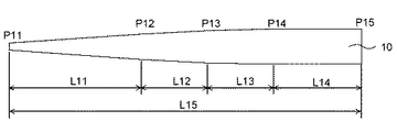
以下本発明のゴルフクラブ用シャフトを製造するための条件を具体的に説明する。例えば、図2に示すような、細径端から太径端に向かって漸次テーパーが減少する形状を有するマンドレル10を用いて、図1のパターン1〜7に示すような裁断形状を有するプリプレグ21〜27を、パターン1〜7の順番でマンドレル10に巻き付けて積層した後、加熱硬化することで得ることが出来る。また、図2中のマンドレルのテーパー度が変わる点P12、P13が、加熱成形後に得られるシャフトの370mmから770mmの領域になるよう調整してパターン1〜7を巻き付けることで、目的とするシャフトを得ることが出来る。
The conditions for producing the golf club shaft of the present invention will be specifically described below. For example, a
本発明の骨子は、上記の領域における曲げ剛性分布が極めて直線に近くすることであるが、従来からある均一なテーパー度のマンドレルでは、曲げ剛性分布が凹型の曲線となってしまう。これを防ぐためには、凸型の曲線形状を有するマンドレルを使用すれば良いが、実際にそのようなマンドレルを精度良く作製することは非常に困難であるため、テーパー度が細径端から太径端に向かって漸次減少するマンドレルを使用することが望ましい。また、上記領域において、曲げ剛性分布を直線状にするためには、細径端部から少なくとも3段階にわたって漸次減少するマンドレルを使用することが好ましく、3段階より少ないと精度良く曲げ剛性分布を直線状にすることが出来ない。また、上記のようにシャフトのテーパー度が漸次減少しているマンドレルにおいても、テーパー度の変化が大きすぎると、今度は本領域における曲げ剛性分布曲線が凸型の曲線形状となってしまい、本発明の意図するものとは異なるため、精度良くマンドレルの形状をコントロールすることが重要である。 The gist of the present invention is that the bending stiffness distribution in the above-mentioned region is very close to a straight line. However, in a conventional mandrel having a uniform taper degree, the bending stiffness distribution becomes a concave curve. In order to prevent this, it is sufficient to use a mandrel having a convex curve shape. However, since it is very difficult to actually manufacture such a mandrel with high accuracy, the taper degree is increased from the small diameter end to the large diameter. It is desirable to use a mandrel that gradually decreases towards the edge. In the above region, in order to make the bending stiffness distribution linear, it is preferable to use a mandrel that gradually decreases from at least three steps from the end of the narrow diameter. I can't make it. In addition, in the mandrel where the taper degree of the shaft gradually decreases as described above, if the change in the taper degree is too large, the bending stiffness distribution curve in this region will become a convex curve shape this time. Since it is different from what is intended by the invention, it is important to accurately control the shape of the mandrel.
<使用形態>
本発明のゴルフクラブ用シャフトは、ゴルフクラブの長さが1041mm〜1219mm、シャフトの質量が40g〜85gのいわゆるウッド用のゴルフクラブシャフトに適用することで、その効果がより十分に発揮される。
<Usage pattern>
When the golf club shaft of the present invention is applied to a so-called wood golf club shaft having a golf club length of 1041 mm to 1219 mm and a mass of the shaft of 40 g to 85 g, the effect is more fully exhibited.
本発明のゴルフクラブ用シャフトは、大型ヘッドとの組み合わせにも好適である。大型ヘッドとしては、体積が380cm3〜460cm3、慣性モーメント3500g・cm2〜5900g・cm2の大型ヘッドが挙げられる。本発明のゴルフクラブ用シャフトは、このような大型ヘッドを装着しても、スイング中のゴルフシャフトのしなり戻りの復元性を高めると同時にヘッドスピードを向上させ、飛距離を向上させることが出来る。 The golf club shaft of the present invention is also suitable for combination with a large head. Examples of the large head include a large head having a volume of 380 cm 3 to 460 cm 3 and an inertia moment of 3500 g · cm 2 to 5900 g · cm 2 . The shaft for a golf club of the present invention can improve the head speed and the flight distance at the same time as improving the resilience of the golf shaft during swinging even when such a large head is mounted. .
次に、実施例に基づいて本発明を更に具体的に説明する。 Next, the present invention will be described more specifically based on examples.
実施例および比較例で作製したゴルフクラブ用シャフトの材料を以下に示す。 The materials for the golf club shafts produced in the examples and comparative examples are shown below.
プリプレグA:炭素繊維プリプレグ MRX350E100R(厚さ0.093mm、三菱レイヨン株式会社製)
プリプレグB:炭素繊維プリプレグ HSX350C100S(厚さ0.076mm、三菱レイヨン株式会社製)
プリプレグC:炭素繊維プリプレグ MR350J050S(厚さ0.050mm、三菱レイヨン株式会社製)
プリプレグD:炭素繊維プリプレグ MRX350C100R(厚さ0.084mm、三菱レイヨン株式会社製)
プリプレグE:炭素繊維プリプレグ MRX350C150S(厚さ0.127mm、三菱レイヨン株式会社製)
プリプレグF:炭素繊維プリプレグ TR350E125S(厚さ0.113mm、三菱レイヨン株式会社製)
(実施例1)
<マンドレル>
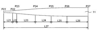
図3に示す形状のマンドレル11(鉄製)を用意した。このマンドレル11は、全体の長さL27にあって、その細径端P21から長さL21の位置(切換点)P22まで、その外径が直線的に漸増し、同様にP22から長さL22の位置P23まで、P23から長さL23の位置P24まで、P24から長さL24の位置P25まで、P25から長さL25の位置P26まで、その外径が直線的に漸増している。そして、切換点P26から長さL26の大径端P27まで、その外径は一定である鉄製の円筒体からなる。本実施例による前記マンドレル11の各部位における具体的な外径、長さ、テーパー度は以下のとおりである。
Prepreg A: Carbon fiber prepreg MRX350E100R (thickness 0.093 mm, manufactured by Mitsubishi Rayon Co., Ltd.)
Prepreg B: Carbon fiber prepreg HSX350C100S (thickness 0.076 mm, manufactured by Mitsubishi Rayon Co., Ltd.)
Prepreg C: Carbon fiber prepreg MR350J050S (thickness 0.050 mm, manufactured by Mitsubishi Rayon Co., Ltd.)
Prepreg D: Carbon fiber prepreg MRX350C100R (thickness 0.084 mm, manufactured by Mitsubishi Rayon Co., Ltd.)
Prepreg E: Carbon fiber prepreg MRX350C150S (thickness 0.127 mm, manufactured by Mitsubishi Rayon Co., Ltd.)
Prepreg F: Carbon fiber prepreg TR350E125S (thickness 0.113 mm, manufactured by Mitsubishi Rayon Co., Ltd.)
Example 1
<Mandrel>
A mandrel 11 (made of iron) having the shape shown in FIG. 3 was prepared. The
細径端P21の外径は4.20mm、切換点P22の外径は5.80mm、切換点P23の外径は7.30mm、切換点P24の外径は10.50mm、切換点P25の外径は12.10mm、切換点P26の外径は13.50mm、この切換点P26から太径端P27までは同一外径であり、その外径は13.50mmである。細径端P21から切替点P22までの長さL21は200mm、切替点P22から切替点P23までの長さL22は100mm、切替点P23から切替点P24までの長さL23は330mm、切替点P24から切替点P25までの長さL24は200mm、切替点P25から切替点P26までの長さL25は200mm、切替点P26から太径端P27までの長さL26は470mmである。マンドレル11の全体長さL27は1500mmとなる。
The outer diameter of the small diameter end P21 is 4.20 mm, the outer diameter of the switching point P22 is 5.80 mm, the outer diameter of the switching point P23 is 7.30 mm, the outer diameter of the switching point P24 is 10.50 mm, outside the switching point P25. The diameter is 12.10 mm, the outer diameter of the switching point P26 is 13.50 mm, the same outer diameter from the switching point P26 to the large diameter end P27, and the outer diameter is 13.50 mm. The length L21 from the small diameter end P21 to the switching point P22 is 200 mm, the length L22 from the switching point P22 to the switching point P23 is 100 mm, the length L23 from the switching point P23 to the switching point P24 is 330 mm, and from the switching point P24 The length L24 from the switching point P25 to the switching point P26 is 200 mm, the length L25 from the switching point P25 to the switching point P26 is 200 mm, and the length L26 from the switching point P26 to the large diameter end P27 is 470 mm. The overall length L27 of the
また、細径端P21から切替点P22までのテーパー度は8.00/1000、切替点P22から切替点P23までのテーパー度は15.00/1000、切替点P23から切替点P24までのテーパー度は9.70/1000、切替点P24から切替点P25までのテーパー度は8.00/1000、切替点P25から切替点P26までのテーパー度は7.00/1000となっている。 Further, the taper degree from the small diameter end P21 to the switching point P22 is 8.00 / 1000, the taper degree from the switching point P22 to the switching point P23 is 15.00 / 1000, and the taper degree from the switching point P23 to the switching point P24. Is 9.70 / 1000, the degree of taper from the switching point P24 to the switching point P25 is 8.00 / 1000, and the degree of taper from the switching point P25 to the switching point P26 is 7.00 / 1000.
<プリプレグの裁断および巻きつけ>
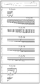
図4のパターン1〜7に示す形状に各種プリプレグ(プリプレグA〜F)を裁断した。これら全てのパターンを、マンドレル11の細径端部から90mmの位置を巻き付け位置の基準点とし、パターンの細径端側をこの基準点に合わせて巻き付ける。これにより、得られるゴルフクラブ用シャフトの細径端部より370mmから770mmにおける領域において、テーパー度が3段階に亘って漸減する形状となる。
<Cutting and winding prepreg>
Various prepregs (prepregs A to F) were cut into shapes shown in
パターン1では、プリプレグAのサイズを、シャフトの長手軸方向に繊維が配向し、図4中のla、lbが、それぞれ、la=110mm、lb=100mmであり、laの範囲では巻き回数が3回となり、lbの範囲では巻き回数が漸減するよう調整した。
In the
パターン2では、シャフトの長手軸方向に対し+45°裁断したプリプレグB、同様に−45°に裁断したプリプレグBを、これらが実質的に半周ずれるようずらして貼り合わせた。そして、この2枚を貼り合わせたプリプレグBのサイズを、全長が1190mmで、巻き回数が3回となるよう調整した。
In the
パターン3では、プリプレグCのサイズを、シャフトの長手軸方向に対し90°に繊維が配向し、全長が1190mmであり、巻き回数が1回となるよう調整した。
In
パターン4〜6では、プリプレグD,Eのサイズを、シャフトの長手軸方向に繊維が配向し、全長が1190mmであり、巻き回数が1回となるよう調整した。 In patterns 4 to 6, the sizes of the prepregs D and E were adjusted so that the fibers were oriented in the longitudinal axis direction of the shaft, the total length was 1190 mm, and the number of windings was one.
パターン7では、プリプレグDのサイズを、シャフトの長手軸方向に繊維が配向し、図4中のlc、ldが、それぞれ、lc=170mm、ld=140mmであり、lcの範囲では巻き回数が2回となり、ldの範囲では巻き回数が漸減するよう調整した。
In the
パターン8では、プリプレグFのサイズを、シャフトの長手軸方向に繊維が配向し、細径端部の外径が8.70mm程度になるよう調整した。
In
次に、それぞれ裁断したプリプレグをパターン1〜7の順番にマンドレル11に巻き付けた。巻き付けは、マンドレルの細径端部から90mmを巻き付けの端部とした。
次に、厚さ20μm、幅30mmの熱収縮性を有するポリプロピレンテープ(不図示)を巻き付けピッチ2mmで巻き付け固定し、マンドレル11に形成したシャフト素管を得た。
Next, the cut prepregs were wound around the
Next, a heat-shrinkable polypropylene tape (not shown) having a thickness of 20 μm and a width of 30 mm was wound and fixed at a winding pitch of 2 mm to obtain a shaft blank formed on the
<樹脂の硬化、およびシャフト素管表面の研磨>
シャフト素管を硬化炉に入れ、145℃で2時間加熱してプリプレグの樹脂の硬化処理を行った後、ポリプロピレンテープとマンドレル11とを取り除いた。得られたゴルフクラブ用シャフト素管の両端を11mmカットして全長を1168mmとした。研磨前のシャフトの片持ちフレックス(細径端から920mmの位置を固定して、シャフト細径端から10mmの位置に3kgの錘を掛けたときのシャフト細径端のたわみ量)は136mmであった。また研磨前のゴルフクラブ用シャフト素管の細径端の外径は8.71mm、太径端の外径は15.27mmであった。
<Hardening of resin and polishing of shaft surface>
The shaft base tube was put in a curing furnace and heated at 145 ° C. for 2 hours to cure the resin of the prepreg, and then the polypropylene tape and the
このゴルフクラブ用シャフト素管を、細径端の外径が8.50mm、片持ちフレックスが152mmとなるよう、円筒研磨機で表面の研磨仕上げを行い、実施例のゴルフクラブ用シャフトを得た。また、得られたゴルフクラブ用シャフトの外径を測定した結果、図11に示す通り、細径端部より370mmから770mmにおける領域において、テーパー度が3段階に亘って漸減する形状が得られた。 The surface of this golf club shaft tube was polished with a cylindrical grinder so that the outer diameter of the narrow end was 8.50 mm and the cantilever flex was 152 mm, and the golf club shaft of the example was obtained. . Further, as a result of measuring the outer diameter of the obtained golf club shaft, as shown in FIG. 11, in the region from 370 mm to 770 mm from the narrow end, a shape in which the taper degree gradually decreased in three stages was obtained. .
実施例のゴルフクラブ用シャフトの質量は59.1g、シャフトのねじれ角(シャフト細径端から1035mmの位置を固定し、シャフト細径端〜シャフト細径端から50mmの位置に、138.5kgf・mmのトルクを掛けたとき、シャフトがねじれた角度。)は3.8度であった。 The weight of the golf club shaft of the example is 59.1 g, and the twist angle of the shaft (fixed at a position of 1035 mm from the shaft small diameter end, 138.5 kgf · The angle at which the shaft was twisted when a torque of mm was applied) was 3.8 degrees.
<シャフトのEI値の測定>
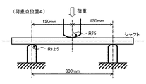
本発明で採用しているシャフトの曲げ剛性EI値は、特開2001−120696公報に記載の方法で求めた。すなわち、図5のように、シャフトを支点間距離300mmで支持し、シャフトの細径端部からの距離L(mm)の位置に荷重20kgを加え、距離L(mm)における曲げたわみ量(mm)を求めた。そして、支点間距離をa(mm)、荷重をb(kg)、曲げたわみ量をc(mm)とし、これらの値から下記式により、距離L(mm)におけるEI値[kgf・mm2]を求めた。
<Measurement of EI value of shaft>
The bending rigidity EI value of the shaft employed in the present invention was determined by the method described in JP-A-2001-120696. That is, as shown in FIG. 5, the shaft is supported at a fulcrum distance of 300 mm, a load of 20 kg is applied to the position of the distance L (mm) from the small diameter end of the shaft, and the bending deflection (mm) at the distance L (mm). ) Then, the distance between the fulcrums is a (mm), the load is b (kg), the amount of bending deflection is c (mm), and from these values, the EI value [kgf · mm 2 ] at the distance L (mm) is calculated by the following formula. Asked.
EI値=(1/48)×(b・a3/c)
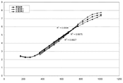
そして、シャフト上の所定位置の曲げ剛性EIL(mm)を計測する計測工程と、シャフトが下部支持ジグに接する位置を太径側に所定の長さずつ移動させて距離Lを増加させて、計測工程を繰り返す反復工程と、計測工程と反復工程とで得られた曲げ変位群(L,EIL)を得る。次に、細径端部より370mmから770mmの領域における50mmごとの距離L(mm)と、前記距離Lの位置における曲げ剛性EIL(×106kgf・mm2)とからなる曲げ剛性群(L,EIL)を(x,y)とし、該(x,y)を最小二乗法により、下記式(A)に直線回帰した後、下記式(A)の相関係数の二乗R1 2を算出すると、0.9994であった(図10参照)。
y=−a1x+b1・・・(A)
<外径の測定>
シャフトの距離L=350〜800mmにおける外径は、マイクロメーターを使用し、25mm間隔で測定した(図11参照)。
EI value = (1/48) × (b · a 3 / c)
Then, a measuring step for measuring the bending rigidity EI L (mm) at a predetermined position on the shaft, and the position where the shaft is in contact with the lower support jig is moved by a predetermined length to the large diameter side to increase the distance L, Obtain the bending displacement group (L, EI L ) obtained by the repetition process of repeating the measurement process and the measurement process and the repetition process. Next, a bending stiffness group consisting of a distance L (mm) for each 50 mm in a region from 370 mm to 770 mm from the narrow-diameter end portion and a bending stiffness EI L (× 10 6 kgf · mm 2 ) at the position of the distance L ( L, EI L ) is (x, y), and (x, y) is linearly regressed to the following formula (A) by the least square method, and then the square of the correlation coefficient of the following formula (A) R 1 2 Was 0.9994 (see FIG. 10).
y = −a 1 x + b 1 (A)
<Measurement of outer diameter>
The outer diameter at a shaft distance L = 350 to 800 mm was measured at intervals of 25 mm using a micrometer (see FIG. 11).
<ゴルフクラブヘッド、およびグリップの取り付け>
実施例のゴルフクラブ用シャフトに、市販のチタン製ドライバー用ゴルフクラブヘッド(体積440cm3、質量203g、ロフト角9.5°)をエポキシ樹脂接着剤で細径端部に取り付けた。さらに、シャフト太径端部を70mmカットし、このシャフトに市販のゴム製グリップを、両面テープを使って取り付け、実施例のゴルフクラブを製作した。
<Attaching the golf club head and grip>
A commercially available titanium golf club head for driver (volume: 440 cm 3 , mass: 203 g, loft angle: 9.5 °) was attached to the small diameter end portion with an epoxy resin adhesive on the golf club shaft of the example. Further, the end of the shaft with a large diameter was cut by 70 mm, and a commercially available rubber grip was attached to the shaft using a double-sided tape to produce a golf club of the example.
<打球の評価>
実施例のゴルフクラブを株式会社ミヤマエ製ゴルフ試打ロボット「SHOTROBO−IV」を用いてゴルフボールを5回打球し、ISG社製「TRACKMAN」にて飛距離計測等の測定を実施した。測定した結果を表1に示す。なお、表1中、回転軸の平均値は、飛球方向を0°とし、回転軸右方向(スライス)を正(+)とし、かつ回転軸左方向(フック)を負(−)として、10回の打球で測定されたそれらの値を足して合算値を算出し、その合算値を打球の回数(5回)で除することで求められた。
<Evaluation of hit ball>
The golf club of the example was hit with a golf ball five times using a golf trial hitting robot “SHOTROBO-IV” manufactured by Miyamae Co., Ltd., and measurement such as flight distance measurement was performed using “TRACKMAN” manufactured by ISG. The measured results are shown in Table 1. In Table 1, the average value of the rotation axis is defined as 0 ° for the flying ball direction, positive (+) for the right direction (slice) of the rotation axis, and negative (-) for the left direction (hook) of the rotation axis. The total value was calculated by adding the values measured in 10 hits, and the total was calculated by dividing the total by the number of hits (5 times).
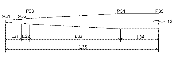
図6に示す形状のマンドレル12(鉄製)を用意した。このマンドレル12は、全体の長さL35にあって、その細径端P31から長さL31の位置(切換点)P32まで、その外径が直線的に漸増し、同様にP32から長さL32の位置P33まで、P33から長さL33の位置P34まで、その外径が直線的に漸増している。そして、切換点P34から長さL34の太径端P35まで、その外径は一定である鉄製の円筒体からなる。本比較例による前記マンドレル12の各部位における具体的な外径、長さ、テーパー度は以下のとおりである。
A mandrel 12 (made of iron) having the shape shown in FIG. 6 was prepared. This
細径端P31の外径は4.15m、切換点P32の外径は5.90mm、切換点P33の外径は7.35mm、切換点P34の外径は13.50mm、この切換点P34から太径端P35までは同一外径であり、その外径は13.50mmである。細径端P31から切替点P32までの長さL31は200mm、切替点P32から切替点P33までの長さL32は100mm、切替点P33から切替点P34までの長さL33は700mm、切替点P34から太径端P35までの長さL34は500mmである。マンドレル12の全体長さL35は1500mmとなる。
The outer diameter of the narrow end P31 is 4.15 m, the outer diameter of the switching point P32 is 5.90 mm, the outer diameter of the switching point P33 is 7.35 mm, the outer diameter of the switching point P34 is 13.50 mm, and from this switching point P34 The outer diameter up to the large diameter end P35 is the same, and the outer diameter is 13.50 mm. The length L31 from the small diameter end P31 to the switching point P32 is 200 mm, the length L32 from the switching point P32 to the switching point P33 is 100 mm, the length L33 from the switching point P33 to the switching point P34 is 700 mm, and from the switching point P34 The length L34 to the large diameter end P35 is 500 mm. The overall length L35 of the
また、細径端P31から切替点P32までのテーパー度は8.75/1000、切替点P32から切替点P33までのテーパー度は14.50/1000、切替点P33から切替点P34までのテーパー度は8.79/1000となっている。 Further, the taper degree from the small diameter end P31 to the switching point P32 is 8.75 / 1000, the taper degree from the switching point P32 to the switching point P33 is 14.50 / 1000, and the taper degree from the switching point P33 to the switching point P34. Is 8.79 / 1000.
このマンドレル12を使用した以外は、実施例と同様にシャフトを作製し、各評価を実施した。評価結果を図10,11に示す。
Except that this
なお、マンドレル12を使用した場合は、得られるゴルフクラブ用シャフトの細径端部より370mmから770mmにおける領域において、図11に示す通り、テーパー度は均一に漸減する形状となる。特許文献1、および特許文献3では、本比較例1と同様のテーパー形状のマンドレルを使用しており、同様の結果が得られると推測される。
When the
比較例1のゴルフクラブ用シャフトの質量は59.4g、シャフトのねじれ角(シャフト細径端から1035mmの位置を固定し、シャフト細径端〜シャフト細径端から50mmの位置に、138.5kgf・mmのトルクを掛けたとき、シャフトがねじれた角度。)は3.8度であった。この比較例1のゴルフクラブ用シャフトを用い、実施例と同様にゴルフクラブを作製して評価を実施した。評価結果を表1に示す。 The weight of the golf club shaft of Comparative Example 1 is 59.4 g, and the twist angle of the shaft (fixed at a position of 1035 mm from the narrow shaft end and 138.5 kgf from the small shaft end to 50 mm from the small shaft end). The angle at which the shaft was twisted when a torque of mm was applied) was 3.8 degrees. Using the golf club shaft of Comparative Example 1, a golf club was produced and evaluated in the same manner as in the Example. The evaluation results are shown in Table 1.
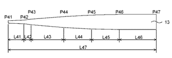
図8に示す形状のマンドレル13(鉄製)を用意した。このマンドレル13は、全体の長さL47にあって、その細径端P41から長さL41の位置(切換点)P42まで、その外径が直線的に漸増し、同様にP42から長さL42の位置P43まで、P43から長さL43の位置P44まで、P44から長さL44の位置P45まで、P45から長さL45の位置P46まで、その外径が直線的に漸増している。そして、切換点P46から長さL46の太径端P47まで、その外径は一定である鉄製の円筒体からなる。本比較例による前記マンドレル13の各部位における具体的な外径、長さ、テーパー度は以下のとおりである。
A mandrel 13 (made of iron) having the shape shown in FIG. 8 was prepared. The
細径端P41の外径は4.20m、切換点P42の外径は5.80mm、切換点P43の外径は7.30mm、切換点P44の外径は10.75mm、切換点P45の外径は12.50mm、切換点P46の外径は13.50mm、この切換点P46から太径端P47までは同一外径であり、その外径は13.50mmである。細径端P41から切替点P42までの長さL41は200mm、切替点P42から切替点P43までの長さL42は100mm、切替点P43から切替点P44までの長さL43は330mm、切替点P44から切替点P45までの長さL44は220mm、切替点P45から切替点P46までの長さL45は230mm、切替点P46から太径端P47までの長さL46は420mmである。マンドレル13の全体長さL47は1500mmとなる。
The outer diameter of the narrow end P41 is 4.20 m, the outer diameter of the switching point P42 is 5.80 mm, the outer diameter of the switching point P43 is 7.30 mm, the outer diameter of the switching point P44 is 10.75 mm, and the outside of the switching point P45. The diameter is 12.50 mm, the outer diameter of the switching point P46 is 13.50 mm, the same outer diameter from the switching point P46 to the large diameter end P47, and the outer diameter is 13.50 mm. The length L41 from the small diameter end P41 to the switching point P42 is 200 mm, the length L42 from the switching point P42 to the switching point P43 is 100 mm, the length L43 from the switching point P43 to the switching point P44 is 330 mm, from the switching point P44. The length L44 from the switching point P45 to the switching point P46 is 220 mm, the length L45 from the switching point P45 to the switching point P46 is 230 mm, and the length L46 from the switching point P46 to the large diameter end P47 is 420 mm. The overall length L47 of the
また、細径端P41から切替点P42までのテーパー度は8.00/1000、切替点P42から切替点P43までのテーパー度は15.00/1000、切替点P43から切替点P44までのテーパー度は10.45/1000、切替点P44から切替点P45までのテーパー度は7.95/1000、切替点P45から切替点P46までのテーパー度は4.35/1000となっている。 Further, the taper degree from the narrow end P41 to the switching point P42 is 8.00 / 1000, the taper degree from the switching point P42 to the switching point P43 is 15.00 / 1000, and the taper degree from the switching point P43 to the switching point P44. Is 10.45 / 1000, the degree of taper from the switching point P44 to the switching point P45 is 7.95 / 1000, and the degree of taper from the switching point P45 to the switching point P46 is 4.35 / 1000.
このマンドレル13を使用した以外は、実施例と同様にシャフトを作製し、各評価を実施した。評価結果を図10,11に示す。
Except that this
なお、マンドレル13を使用した場合は、得られるゴルフクラブ用シャフトの細径端部より370mmから770mmにおける領域において、図11に示す通り、テーパー度が3段階に亘って漸減する形状となるが、本領域における曲げ剛性分布を直線回帰した後、直線近似式の相関係数の二乗R1 2を算出すると、0.9975であった。
When the
比較例2のゴルフクラブ用シャフトの質量は59.1g、シャフトのねじれ角(シャフト細径端から1035mmの位置を固定し、シャフト細径端〜シャフト細径端から50mmの位置に、138.5kgf・mmのトルクを掛けたとき、シャフトがねじれた角度。)は3.7度であった。この比較例2のゴルフクラブ用シャフトを用い、実施例と同様にゴルフクラブを作製して評価を実施した。評価結果を表1に示す。 The weight of the golf club shaft of Comparative Example 2 is 59.1 g, and the twist angle of the shaft (fixed at a position of 1035 mm from the shaft small diameter end and 138.5 kgf at a position from the shaft small diameter end to the shaft small diameter end to 50 mm) The angle at which the shaft was twisted when a torque of mm was applied) was 3.7 degrees. Using the golf club shaft of Comparative Example 2, a golf club was produced and evaluated in the same manner as in the Example. The evaluation results are shown in Table 1.
このように、実施例におけるゴルフクラブ用シャフトでは、ヘッドスピードが速くなると同時にバックスピン量が減少させることが出来るので、平均飛距離の増大が期待できる。 As described above, in the golf club shaft according to the embodiment, the head spin rate can be increased and the backspin amount can be decreased at the same time, so that an increase in the average flight distance can be expected.
Claims (2)
前記ゴルフクラブ用シャフトの細径端部より370mmから770mmの領域における50mmごとの距離L(mm)と、前記距離Lの位置における曲げ剛性EIL(×106kgf・mm2)とからなる曲げ剛性群(L,EIL)を(x,y)とし、該(x,y)を最小二乗法により下記式(A)に直線回帰した場合に、下記式(A)の相関係数の二乗R1 2が0.999以上であり、
y=−a1x+b1・・・式(A)
前記ゴルフクラブ用シャフトの細径端部より370mmから770mmの領域におけるゴルフクラブ用シャフトのテーパーが、細径端部側から少なくとも3段階にわたって漸次減少し、
成型されるゴルフクラブ用シャフトの細径端部より370mmから770mmの領域におけるテーパーが、細径端部側から少なくとも3段階にわたって漸次減少するよう、テーパー度が複数段に亘り漸次減少しているマンドレルを使用して成形する
ことを特徴とするゴルフクラブ用シャフトの製造方法。 A method for producing a golf club shaft comprising a prepreg formed by impregnating a reinforcing fiber with a resin and wound around a mandrel,
Bending the distance of each 50mm from 370mm from the small diameter end of the golf club shaft in the region of 770 mm L (mm), Naru Kara flexural rigidity EI L and (× 10 6 kgf · mm 2 ) at the position of the distance L When the stiffness group (L, EI L ) is (x, y) and the (x, y) is linearly regressed to the following formula (A) by the least square method, the square of the correlation coefficient of the following formula (A) R 1 2 is 0.999 or more,
y = -a 1 x + b 1 Formula (A)
The taper of the golf club shaft in a region of 370 mm to 770 mm from the narrow end portion of the golf club shaft gradually decreases from at least three steps from the narrow end portion side,
The mandrel in which the taper degree gradually decreases over a plurality of stages so that the taper in the region of 370 mm to 770 mm from the narrow end of the golf club shaft to be molded gradually decreases over at least three stages from the narrow end side. Mold using
A method for producing a shaft for a golf club .
Priority Applications (1)
| Application Number | Priority Date | Filing Date | Title |
|---|---|---|---|
| JP2012122093A JP6182829B2 (en) | 2012-05-29 | 2012-05-29 | Manufacturing method of shaft for golf club |
Applications Claiming Priority (1)
| Application Number | Priority Date | Filing Date | Title |
|---|---|---|---|
| JP2012122093A JP6182829B2 (en) | 2012-05-29 | 2012-05-29 | Manufacturing method of shaft for golf club |
Publications (2)
| Publication Number | Publication Date |
|---|---|
| JP2013244345A JP2013244345A (en) | 2013-12-09 |
| JP6182829B2 true JP6182829B2 (en) | 2017-08-23 |
Family
ID=49844578
Family Applications (1)
| Application Number | Title | Priority Date | Filing Date |
|---|---|---|---|
| JP2012122093A Active JP6182829B2 (en) | 2012-05-29 | 2012-05-29 | Manufacturing method of shaft for golf club |
Country Status (1)
| Country | Link |
|---|---|
| JP (1) | JP6182829B2 (en) |
Families Citing this family (1)
| Publication number | Priority date | Publication date | Assignee | Title |
|---|---|---|---|---|
| JP6822023B2 (en) * | 2016-09-09 | 2021-01-27 | 住友ゴム工業株式会社 | Golf club shaft |
Family Cites Families (6)
| Publication number | Priority date | Publication date | Assignee | Title |
|---|---|---|---|---|
| JP3433793B2 (en) * | 1998-10-28 | 2003-08-04 | 横浜ゴム株式会社 | Iron golf club set |
| JP2002224256A (en) * | 2000-12-01 | 2002-08-13 | Mizuno Corp | Golf shaft and golf club to which golf shaft is attached |
| JP2002177423A (en) * | 2000-12-12 | 2002-06-25 | Sumitomo Rubber Ind Ltd | Golf club shaft and golf club shaft series |
| JP2003180891A (en) * | 2001-12-17 | 2003-07-02 | Keiji Fujimaru | Golf club shaft and golf club using the same |
| JP4335289B1 (en) * | 2008-03-14 | 2009-09-30 | 藤倉ゴム工業株式会社 | Golf club shaft and golf club |
| US8029382B2 (en) * | 2008-03-24 | 2011-10-04 | Taylor Made Golf Company, Inc. | Golf-club shafts having selectable-stiffness tip regions, and golf clubs comprising same |
-
2012
- 2012-05-29 JP JP2012122093A patent/JP6182829B2/en active Active
Also Published As
| Publication number | Publication date |
|---|---|
| JP2013244345A (en) | 2013-12-09 |
Similar Documents
| Publication | Publication Date | Title |
|---|---|---|
| US7736245B2 (en) | Golf club shaft and golf club | |
| JP2007135963A (en) | Golf club shaft | |
| JP2001087436A (en) | Golf club shaft | |
| US6866593B1 (en) | Golf club shaft having multiple metal fiber layers | |
| US20040009827A1 (en) | Golf club shaft | |
| JP2018020206A (en) | Golf club shaft | |
| JP2010063778A (en) | Shaft for golf club and method for manufacturing the same | |
| JP6182829B2 (en) | Manufacturing method of shaft for golf club | |
| JP2008200116A (en) | Iron type golf club shaft and iron type golf club | |
| JP5356265B2 (en) | Golf club shaft and manufacturing method thereof | |
| JPH11319170A (en) | Golf club shaft and golf club | |
| CN108371795B (en) | Club body matched with metal type golf club and metal type golf club | |
| JP5291356B2 (en) | Golf club shaft | |
| JP2003180890A (en) | Golf club shaft | |
| JPH084646B2 (en) | Golf club shaft | |
| JP7729115B2 (en) | Golf club shaft | |
| JP7581767B2 (en) | Golf Club Shafts | |
| JP4576591B2 (en) | Racket frame | |
| JP4571599B2 (en) | Golf club shaft and golf club | |
| JP2008200117A (en) | Iron type golf club shaft and iron type golf club | |
| JP4102487B2 (en) | Golf club shaft made of fiber reinforced plastic | |
| JP6213063B2 (en) | Golf club shaft | |
| JP2011087799A (en) | Golf club shaft | |
| KR20070096814A (en) | Golf club shaft | |
| JP4694058B2 (en) | Manufacturing method of shaft for golf club |
Legal Events
| Date | Code | Title | Description |
|---|---|---|---|
| A621 | Written request for application examination |
Free format text: JAPANESE INTERMEDIATE CODE: A621 Effective date: 20150518 |
|
| A131 | Notification of reasons for refusal |
Free format text: JAPANESE INTERMEDIATE CODE: A131 Effective date: 20160623 |
|
| A977 | Report on retrieval |
Free format text: JAPANESE INTERMEDIATE CODE: A971007 Effective date: 20160624 |
|
| A521 | Written amendment |
Free format text: JAPANESE INTERMEDIATE CODE: A523 Effective date: 20160802 |
|
| A131 | Notification of reasons for refusal |
Free format text: JAPANESE INTERMEDIATE CODE: A131 Effective date: 20161124 |
|
| A521 | Written amendment |
Free format text: JAPANESE INTERMEDIATE CODE: A523 Effective date: 20170120 |
|
| TRDD | Decision of grant or rejection written | ||
| A01 | Written decision to grant a patent or to grant a registration (utility model) |
Free format text: JAPANESE INTERMEDIATE CODE: A01 Effective date: 20170627 |
|
| A61 | First payment of annual fees (during grant procedure) |
Free format text: JAPANESE INTERMEDIATE CODE: A61 Effective date: 20170710 |
|
| R151 | Written notification of patent or utility model registration |
Ref document number: 6182829 Country of ref document: JP Free format text: JAPANESE INTERMEDIATE CODE: R151 |