JP6180219B2 - Sterilizer - Google Patents
Sterilizer Download PDFInfo
- Publication number
- JP6180219B2 JP6180219B2 JP2013159160A JP2013159160A JP6180219B2 JP 6180219 B2 JP6180219 B2 JP 6180219B2 JP 2013159160 A JP2013159160 A JP 2013159160A JP 2013159160 A JP2013159160 A JP 2013159160A JP 6180219 B2 JP6180219 B2 JP 6180219B2
- Authority
- JP
- Japan
- Prior art keywords
- hydrogen peroxide
- fluid nozzle
- peroxide solution
- air
- air compressor
- Prior art date
- Legal status (The legal status is an assumption and is not a legal conclusion. Google has not performed a legal analysis and makes no representation as to the accuracy of the status listed.)
- Active
Links
Images

Landscapes
- Apparatus For Disinfection Or Sterilisation (AREA)
- Disinfection, Sterilisation Or Deodorisation Of Air (AREA)
Description
本発明は、過酸化水素ガスを用いて殺菌を行う殺菌装置に関する。 The present invention relates to sterilization equipment for performing sterilization using hydrogen peroxide gas.
従来、密閉空間や密閉空間に配置された製品や装置等の対象物を殺菌する方法として、ホルムアルデヒドを用いた薫蒸殺菌する技術が知られていた。しかし、ホルムアルデヒドは発がん性を指摘されており、人体への影響等の問題がある。そこで、安全性や生産性の高い過酸化水素ガス(Vapor Hydrogen Peroxide)を用いた殺菌方法が知られている。 Conventionally, as a method for sterilizing an object such as a product or a device disposed in a sealed space or a sealed space, a technique for fumigating using formaldehyde has been known. However, formaldehyde has been pointed out to be carcinogenic and has problems such as effects on the human body. Therefore, a sterilization method using hydrogen peroxide gas (Vapor Hydrogen Peroxide) with high safety and high productivity is known.
このような過酸化水素ガスを用いた殺菌装置として、発生器を備え、発生器から過酸化水素ガスを密閉空間内に供給して充満させることで、過酸化水素ガスのラジカルにより微生物のDNA、細胞壁又は酵素等を破壊して殺菌を行う技術が知られている(例えば、特許文献1及び特許文献2参照)。
As a sterilization apparatus using such hydrogen peroxide gas, a generator is provided, and by supplying hydrogen peroxide gas from the generator into a sealed space to be filled, the DNA of microorganisms is generated by radicals of hydrogen peroxide gas, Techniques for sterilizing by destroying cell walls or enzymes are known (see, for example,
また、多孔性包材からなる包装容器に封入されたプレフィルドシリンジの表面を殺菌するために、プレフィルドシリンジの表面温度を管理するとともに、その後、別の温度及び湿度を管理して殺菌を行う殺菌方法も知られている(例えば、特許文献3参照)。他にも、密閉空間内の過酸化水素蒸気の濃度を急速に上昇させ、その後、当該濃度が所定濃度以下となった場合に、密閉空間の過酸化水素蒸気を除去する殺菌方法も知られている(例えば、特許文献4参照)。 In addition, in order to sterilize the surface of the prefilled syringe enclosed in a packaging container made of a porous packaging material, the surface temperature of the prefilled syringe is controlled, and then another temperature and humidity are controlled to perform sterilization. Is also known (see, for example, Patent Document 3). Another known sterilization method is to rapidly increase the concentration of hydrogen peroxide vapor in the enclosed space and then remove the hydrogen peroxide vapor in the enclosed space when the concentration falls below a predetermined concentration. (For example, see Patent Document 4).
このような殺菌装置に用いられる発生器は、過酸化水素水を貯留するタンクと、所定の温度に加熱されるプレートヒータと、プレートヒータにタンク内の過酸化水素水を供給する供給手段と、を備える構成が知られている。発生器は、プレートヒータに過酸化水素水を適量供給することで、過酸化水素ガスを発生可能に形成されている。 A generator used in such a sterilizer includes a tank for storing hydrogen peroxide water, a plate heater heated to a predetermined temperature, a supply means for supplying the hydrogen peroxide solution in the tank to the plate heater, There is a known configuration comprising: The generator is configured to generate hydrogen peroxide gas by supplying an appropriate amount of hydrogen peroxide water to the plate heater.
上述した殺菌装置では、以下の問題があった。即ち、上述した殺菌装置の発生器は、定置式の熱源(プレートヒータ)があり、発生したガスを拡散させるブロアが必要となる。さらにこのような熱源部を外郭部材に収納しなければならない構成であることから、これらを組み合せた殺菌装置は大型となる、という問題があった。このためクリーンルームのような大規模空間(例えば、数百m3レベル)に適用することは可能であるが、一般居室(例えば、数十m3レベル)への適用は難しい。そこで、小型化が可能な殺菌装置の要望があった。 The sterilizer described above has the following problems. That is, the sterilizer generator described above has a stationary heat source (plate heater) and requires a blower for diffusing the generated gas. Furthermore, since such a heat source part must be housed in the outer member, there has been a problem that a sterilizer that combines these heat sources becomes large. Therefore, it can be applied to a large-scale space such as a clean room (for example, several hundred m 3 level), but it is difficult to apply to a general living room (for example, several tens of m 3 level). Therefore, there has been a demand for a sterilizer that can be downsized.
そこで本発明は、過酸化水素ガスを用いて殺菌を行う殺菌装置を提供することを目的とする。 Accordingly, the present invention aims at providing a sterilizing equipment for performing sterilization using hydrogen peroxide gas.
前記課題を解決し目的を達成するために、本発明の殺菌装置は、次のように構成されている。 To achieve the solution to the purpose of the problem, sterilizing equipment of the present invention is constructed as follows.
本発明の一態様として、殺菌装置は、供給された過酸化水素水及び空気を混合して噴射することで、過酸化水素水を霧状にする二流体ノズルと、前記二流体ノズルから噴射された前記過酸化水素水を加熱し、気化させる加熱装置と、前記二流体ノズルに前記過酸化水素水を供給するポンプと、前記二流体ノズルに前記空気を供給するエアコンプレッサと、前記二流体ノズル及び前記エアコンプレッサと接続され、前記二流体ノズルから噴射される前記過酸化水素水及び前記エアコンプレッサから供給される前記空気を合流させて二次側に移動させる合流管と、を備え、前記二流体ノズル及び前記ポンプ、前記二流体ノズル及び前記エアコンプレッサ、並びに、前記合流管及び前記エアコンプレッサは、可撓性を有する配管で接続され、前記二流体ノズル、前記合流管及び前記加熱装置は、持ち運び可能に一体に構成される。 As one aspect of the present invention, the sterilizer mixes and sprays the supplied hydrogen peroxide solution and air, thereby spraying the hydrogen peroxide solution into a mist, and the two fluid nozzles inject the two-fluid nozzle. A heating device that heats and vaporizes the hydrogen peroxide solution, a pump that supplies the hydrogen peroxide solution to the two-fluid nozzle, an air compressor that supplies the air to the two-fluid nozzle, and the two-fluid nozzle. And a joining pipe that is connected to the air compressor and joins the hydrogen peroxide solution ejected from the two-fluid nozzle and the air supplied from the air compressor to move to the secondary side. The fluid nozzle and the pump, the two-fluid nozzle and the air compressor, the merging pipe and the air compressor are connected by a flexible pipe, and the two Body nozzle, the merging pipe and the heating device, portable configured integrally.
本発明によれば、小型化が可能な殺菌装置を提供することが可能となる。 According to the present invention, it is possible to provide a sterilization equipment can be downsized.
以下、本発明の一実施形態に関わる殺菌装置1の構成を、図1及び図2を用いて説明する。
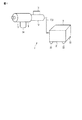
図1は本発明の一実施形態に係る殺菌装置1の構成を模式的に示す斜視図、図2は殺菌装置1の構成を模式的に示す説明図である。
Hereinafter, the configuration of the
FIG. 1 is a perspective view schematically showing a configuration of a
殺菌装置1は、室内等の空間や殺菌対象物を過酸化水素ガス(VHP:Vapor Hydrogen Peroxide)により殺菌可能に形成されている。殺菌装置1は、殺菌を行う空間、又は、殺菌対象物の周囲の空間の過酸化水素ガスの濃度(VHP濃度)が低濃度帯での殺菌に用いられる。ここで、低濃度帯とは、人体及び装置に損傷を与えることが防止可能な空間のVHP濃度であって、例えば、空間内の過酸化水素ガスの濃度が100ppm以下の範囲である。
The
図1に示すように、殺菌装置1は、過酸化水素ガスを空間又は殺菌対象物に供給する供給装置5と、供給装置5を駆動する駆動装置6と、を備えている。殺菌装置1は、供給装置5及び駆動装置6が配管7及び信号線8によって流体的及び電気的に接続されている。
As shown in FIG. 1, the
殺菌装置1は、空間又は殺菌対象物に対して供給装置5を移動可能、且つ、過酸化水素ガスを供給可能に形成される。
The
なお、殺菌装置1に用いられる過酸化水素水は、例えば、35w/w%の濃度の過酸化水素水が用いられる。
The hydrogen peroxide solution used in the
また、殺菌装置1は、二流体ノズル11と、合流管12と、加熱装置13と、回収タンク14と、エアコンプレッサ15と、ポンプ16と、タンク17と、加熱装置調整手段18と、制御部19と、を備えている。
The
殺菌装置1は、エアコンプレッサ15で供給された空気及びポンプ16で供給された過酸化水素水を二流体ノズル11で噴射し、この噴射された過酸化水素水を加熱装置13で加熱することで、過酸化水素ガスを発生可能に形成されている。
The
供給装置5は、使用者が支持可能、且つ、支持した状態で移動(持ち運び)可能な大きさに形成されている。供給装置5は、二流体ノズル11、合流管12、加熱装置13及び回収タンク14を一体に接続することで、使用者によって搬送可能に形成されている。
The supply device 5 is formed in a size that can be supported by the user and can be moved (carried) in a supported state. The supply device 5 is formed so as to be transportable by the user by connecting the two-
駆動装置6は、外郭体21を備え、外郭体21内にエアコンプレッサ15、ポンプ16、タンク17、加熱装置調整手段18及び制御部19を収納することで構成される。また、駆動装置6は、外郭体21に複数のキャスター22を備え、供給装置5の移動に伴って移動可能に形成されている。
The
配管7は、可撓性を有している。より具体的には、供給装置5及び駆動装置6を接続する配管7は、少なくとも可撓性を有する。例えば、二流体ノズル11及びエアコンプレッサ15、合流管12及びエアコンプレッサ15、並びに、二流体ノズル11及びポンプ16を接続する配管7は、可撓性を有する。また、過酸化水素水を通過させる配管7は、耐食性を有する材料で形成される。信号線8は、可撓性を有している。より具体的には、供給装置5及び駆動装置6を接続する信号線8は、少なくとも可撓性を有する。
Pipe 7 has a flexible. More specifically, the
二流体ノズル11は、配管7を介してエアコンプレッサ15及びポンプ16に接続される。二流体ノズル11は、液体及び気体を混合して噴射可能に形成されている。具体的には、二流体ノズル11は、エアコンプレッサ15で供給された空気及びポンプ16で供給された過酸化水素水を混合することで、過酸化水素水を霧状に噴射可能に形成されている。
The two-
合流管12は、二流体ノズル11が設けられるとともに、エアコンプレッサ15に配管7を介して接続されている。合流管12は、エアコンプレッサ15から供給された空気を通過可能、且つ、通過する空気の流れ方向に対して二流体ノズル11から噴射される過酸化水素水が交差して通過する空気の流れ合流するように、二軸が交差して形成される。即ち、合流管12は、流体の供給側が2つ設けられるとともに、中途部で合流することで、吐出側が1つのみ設けられる。
The
合流管12は、例えば、エアコンプレッサ15から供給された空気の流れ方向に対して、二流体ノズル11から噴射される過酸化水素水が直交方向に噴射される、T字状に形成される。なお、合流管12は、エアコンプレッサ15から供給される空気の流れ方向に対して二流体ノズル11から噴射される過酸化水素水が交差する形状であれば、Y字状や他の形状であってもよい。
For example, the
加熱装置13は、管体31と、管体31内に配置されたヒータ32と、を備えている。加熱装置13は、合流管12からの過酸化水素水及び空気を通過させることで、ヒータ32により過酸化水素水を加熱し、過酸化水素ガスを発生させる。
The
管体31は、合流管12と接続される。管体31は、例えば、その内部を通過する流体の流れ方向が、合流管12内を流れるエアコンプレッサ15から供給される空気の流れ方向と同一方向に形成されている。換言すると、管体31は、その軸心方向が、合流管12の空気の流れ方向に沿った軸心と平行に形成されている。管体31は、その先端に、過酸化水素ガスを噴射する噴射口33が形成されている。噴射口33は、管体31のヒータ32が収納されている部位の流路面積(内径)よりも、その開口面積(内径)が小さく形成されている。
The
ヒータ32は、管体31内に配置され、管体31内を通過する過酸化水素水を直接的及び間接的に蒸発させる、即ち気化させることで、過酸化水素ガスを発生させることが可能に形成されている。ヒータ32は、例えば、コイル状に形成され、抵抗加熱により発熱する、所謂伝熱ヒータと呼ばれる発熱体である。ヒータ32は、信号線8を介して加熱装置調整手段18に電気的に接続されている。ヒータ32は、例えば、100Wで400℃に加熱可能に形成されている。
The
回収タンク14は、ヒータ32によって気化されずに液状の状態が維持された過酸化水素水を回収可能に形成された回収装置である。例えば、回収タンク14は、配管7を介して管体31の下部に接続されることで、管体31内の下部に溜まった液状の過酸化水素水を回収する。また、回収タンク14は、配管7を介して二流体ノズル11及びタンク17に接続される。回収タンク14は、回収した過酸化水素水の一部を二流体ノズル11に供給し、回収した過酸化水素水の他部をタンク17に供給可能に形成されている。
The
エアコンプレッサ15は、空気を圧縮可能に形成されている。エアコンプレッサ15は、配管7を介して二流体ノズル11及び合流管12にそれぞれ接続されている。エアコンプレッサ15は、圧縮した空気を二流体ノズル11及び合流管12にそれぞれ供給可能に形成されている。
The
エアコンプレッサ15は、二流体ノズル11及び合流管12に異なる圧力の空気を供給可能に形成されている。例えば、エアコンプレッサ15は、0.2MPa以下であって、且つ、二流体ノズル11が霧状の過酸化水素水を噴射可能な圧力の空気を二流体ノズル11に供給可能に形成されている。また、例えば、エアコンプレッサ15は、合流管12に、0.3MPa以下であって、且つ、二流体ノズル11から噴射された過酸化水素水を合流管12の二次側に移動させることが可能な圧力の空気を供給可能に形成されている。
The
ポンプ16は、過酸化水素水を供給可能に形成されている。ポンプ16は、配管7を介して、吸込側がタンク17に、吐出側が二流体ノズル11に、それぞれ接続される。ポンプ16は、例えば、小型のチューブポンプであって、二流体ノズル11に、一定量の過酸化水素水を供給する。例えば、ポンプ16は、過酸化水素水を、0.1g/min乃至0.2g/minで二流体ノズル11に供給可能に形成されている。
The
タンク17は、過酸化水素水を貯留可能に形成される。
The
加熱装置調整手段18は、ヒータ32を加熱可能、且つ、ヒータ32の加熱温度を調整可能に形成されている。加熱装置調整手段18は、例えば、インバータ41及びブレーカ42により構成され、ヒータ32へ供給する電力を調整可能に形成されている。
The heating device adjusting means 18 is formed so that the
インバータ41は、ヒータ32を過酸化水素水の沸点よりも高い温度に加熱可能に形成されている。インバータ41は、35w/w%の濃度の過酸化水素水が用いられる場合には、ヒータ32を120℃以上、より好ましくは200℃乃至400℃に加熱する。
The
なお、ここで、ヒータ32の加熱温度の120℃以上とは、過酸化水素水の沸点以上の温度である。過酸化水素は、100w/w%で140℃、35w/w%で108℃である。このように、インバータ41は、ヒータ32を少なくとも過酸化水素水の沸点以上の温度に加熱可能に形成される。
Here, the heating temperature of the
例えば、インバータ41は、ポンプ16による過酸化水素水の供給量が、1g/minであるときに、ヒータ32を200℃に加熱する。また、例えば、インバータ41は、ポンプ16による過酸化水素水の供給量が2g/minであるときに、ヒータ32を300℃に加熱する。
For example, the
ブレーカ42は、ヒータ32の温度が所定の温度(閾値)を超えた場合にヒータ32への電力の供給を停止可能、且つ、ヒータ32の温度が所定の温度以下となった場合に、ヒータ32への電力を供給可能に形成されている。なお、所定の温度とは、インバータ41により加熱されるヒータ32の温度以上である。
The
制御部19は、信号線8を介して、エアコンプレッサ15、ポンプ16及びインバータ41に接続されている。制御部19は、エアコンプレッサ15の駆動を制御可能に形成されている。制御部19は、エアコンプレッサ15を制御することで、例えば、二流体ノズル11及び合流管12への圧縮空気の圧力及び供給量等を調整可能に形成されている。
The
制御部19は、ポンプ16の駆動を制御可能に形成されている。制御部19は、ポンプ16を制御することで、例えば、過酸化水素水の二流体ノズル11への供給量を調整可能に形成されている。制御部19は、インバータ41を制御可能に形成されている。制御部19は、インバータ41を制御することで、例えば、ヒータ32の温度を調整可能に形成されている。
The
このように構成された殺菌装置1の使用方法について、以下説明する。
先ず、使用者は、殺菌を行う対象物の付近に、供給装置5及び駆動装置6を移動させる。次に、制御部19により、エアコンプレッサ15及びポンプ16を駆動するとともに、インバータ41を制御してヒータ32を所定の温度に加熱する。これにより、供給装置5が駆動される。具体的に説明すると、エアコンプレッサ15が駆動されることで、二流体ノズル11及び合流管12に所定の圧力の空気が供給される。
A method of using the
First, the user moves the supply device 5 and the
また、ポンプ16が駆動されることで、図2に矢印で示すように、タンク17内の過酸化水素水が二流体ノズル11に供給される。なお、このとき、空気及び過酸化水素水が二流体ノズル11に供給されることで、二流体ノズル11から霧状の過酸化水素水が合流管12内に噴射される。
Further, by driving the
二流体ノズル11から噴射された霧状の過酸化水素水は、合流管12内の空気の流れと合流し、合流管12の二次側、即ち管体31内に移動する。管体31内に移動した霧状の過酸化水素水は、その一部がヒータ32に直接接触し、且つ、その他部がヒータ32により加熱された管体31内の空間(空気)によって気化して過酸化水素ガスが発生する。過酸化水素ガスは、エアコンプレッサ15から供給された空気の流れによって、噴射口33から噴射される。
The atomized hydrogen peroxide solution ejected from the two-
使用者は、殺菌を行う対象物の付近に、供給装置5及び駆動装置6を移動させるとともに、過酸化水素ガスが噴射される供給装置5を支持し、噴射口33を対象物に対向させて、過酸化水素ガスを対象物に噴射する。例えば、使用者は、対象物が所定の殺菌効果を得られるまで所定の時間噴射を継続して行い、対象物の殺菌を行う。
The user moves the supply device 5 and the
なお、このとき、加熱装置13内で気化されない過酸化水素水は、管体31内面に付着して管体31の底部に移動し、回収タンク14に回収される。回収タンク14に回収された過酸化水素水は、図2中に矢印で示すように、一部が二流体ノズル11に供給され、他部がタンク17に供給、即ちタンク17に回収される。このように、気化されず、液状の過酸化水素水は、循環して直接又はタンク17及びポンプ16を介して二流体ノズル11に供給される。
At this time, the hydrogen peroxide solution that is not vaporized in the
殺菌終了後、使用者は、エアコンプレッサ15及びポンプ16を停止させるとともに、ヒータ32への電力供給を停止することで、供給装置5を停止する。
After the sterilization is completed, the user stops the supply device 5 by stopping the
このように構成された殺菌装置1によれば、二流体ノズル11で噴射した霧状の過酸化水素水を、空気によって加熱装置13を通過させることで、過酸化水素ガスを発生させることが可能となる。
According to the
また、殺菌装置1は、二流体ノズルで過酸化水素水を霧状として加熱装置13を通過させ、加熱装置13のヒータ32により直接又は間接的に過酸化水素水を加熱して気化させることで、過酸化水素ガスを発生させる構成である。このため、ヒータ32は、霧状の過酸化水素水が通過可能な管体31内に配置可能であって、且つ、霧状の過酸化水素水を気化可能な構成であればよく、ヒータ32を小型とすることが可能となる。
Moreover, the
特に、発生させる過酸化水素ガスの量が多い場合には、ヒータ32の熱量を増加させるか、通過する霧状の過酸化水素水がヒータ32に直接接触するように、ヒータ32の表面積を増加させるか、又は、通過する霧状の過酸化水素水が直接接触する形状及び配置等とすればよい。このように、ヒータ32の小型化が可能となることで、殺菌装置1の小型化が可能となる。
In particular, when the amount of hydrogen peroxide gas to be generated is large, the amount of heat of the
また、殺菌装置1は、ヒータ32を小型とすることで、ヒータ32の軽量化が可能となる。このため、殺菌装置1は、供給装置5として二流体ノズル11、合流管12及び加熱装置13を一体に構成することで、使用者が供給装置5を支持することが可能となる。また、殺菌装置1は、供給装置5を駆動するエアコンプレッサ15、ポンプ16、タンク17、加熱装置調整手段18及び制御部19を駆動装置6として外郭体21内に一体に構成し、例えば、キャスター22を設けることで、供給装置5の持ち運びに伴って移動させることが可能となる。これにより、殺菌装置1は、対象物に直接過酸化水素ガスを噴射して当該対象物を殺菌することが可能となる。
Moreover, the
即ち、殺菌装置1は、供給装置5及び駆動装置6を任意の場所に持ち運ぶとともに、供給装置5を支持して噴射口33を対象物に対向させることで、対象物のみを殺菌することが可能となる。このような殺菌装置1を用いることで、培養恒温庫、キャビネット内部、HEPA、水回りの隙間等の固定設備を対象物とした殺菌が可能となる。このように、殺菌装置1は、持ち運び可能、且つ、噴射口33を任意の位置に向って指向することが可能な構成とすることで、局所的に殺菌することが可能となる。
That is, the
また、殺菌装置1は、持ち運びが可能となることで、別途発生したガスを拡散させるブロアを必要とせず、簡素な構成とすることが可能となる。これにより殺菌装置1は、殺菌時の殺菌装置1の設置や収納等において作業が減少し、使用性が向上する。
Further, since the
上述したように、本発明の一実施の形態に係る殺菌装置1によれば、過酸化水素水を霧状とし、且つ、霧状の過酸化水素水を気化可能なヒータ32を用いることで、小型化が可能となる。
As described above, according to the
なお、本発明は上述した本発明は前記実施の形態に限定されるものではない。上述した例では、加熱装置13は、二流体ノズル11及び合流管12の二次側に設けられる構成を説明したがこれに限定されない。例えば、加熱装置13は、二流体ノズル11及び合流管12の一次側であって、且つ、エアコンプレッサ15の二次側に配置する構成であってもよい。このように、殺菌装置1は、エアコンプレッサ15から噴射された空気が、加熱装置13を通過することでヒータ32により加熱される。この加熱された空気(熱風)によって霧状の過酸化水素水を気化させる構成であってもよい。また、加熱装置13を二流体ノズル11及び合流管12の一次側及び二次側にそれぞれ設けて過酸化水素水を気化させる構成であってもよい。
Note that the present invention is not limited to the above-described embodiment. In the example mentioned above, although the
上述した例では、殺菌装置1は、加熱装置13として、管体31内にヒータ32を設けるとともに、管体31の下部に回収タンク(回収装置)14を設ける構成を説明したが、これに限定されない。ヒータ32の配置等によって、管体31を通過する過酸化水素水を略全て気化させる構成とするのであれば、回収タンク14を設けなくてもよい。なお、過酸化水素水を略全てを気化させるヒータ32の配置として、例えば、管体31の下方に溜まる過酸化水素水を加熱し、気化させるヒータ32を別途設けるか、又は、ヒータ32を延設する構成等であってもよい。但し、ヒータ32の煩雑化や、製造コスト及び消費電力の増加となる場合においては、回収タンク14を設ける構成が好ましい。
In the above-described example, the
上述した例では、回収タンク14は、回収した過酸化水素水を二流体ノズル11及びタンク17に供給する(戻す)構成を説明したがこれに限定されない。回収タンク14は、二流体ノズル11及びタンク17のいずれか一方に回収した過酸化水素水を供給する構成であってもよく、また、回収タンク14が過酸化水素水を霧状として回収した過酸化水素水を管体31内に供給する構成であってもよい。
In the above-described example, the
上述した例では、エアコンプレッサ15が二流体ノズル11及び合流管12に接続される構成のみを説明したがこれに限定されない。例えば、エアコンプレッサ15と二流体ノズル11及び合流管12をそれぞれ接続する配管7に、使用者が開閉可能な開閉弁を設け、過酸化水素ガスを噴射するときにのみ開閉弁を解放して過酸化水素ガスを噴射する構成であってもよい。
In the above-described example, only the configuration in which the
上述した例では、供給装置5は、二流体ノズル11、合流管12、加熱装置13及び回収タンク14を一体に接続する構成を説明したがこれに限定されない。例えば、供給装置5は、断熱性及び耐食性を有し、使用者が供給装置5支持をするのに適した外郭体を設ける構成であってもよい。
In the example described above, the supply device 5 has been described with the configuration in which the two-
また、上述した例では、供給装置5は、二流体ノズル11、合流管12、加熱装置13及び回収タンク14を一体に接続して構成され、駆動装置6は、外郭体21内にエアコンプレッサ15、ポンプ16、タンク17、加熱装置調整手段18及び制御部19を収納する構成を説明したがこれに限定されない。即ち、供給装置5及び駆動装置6は、供給装置5が使用者によって支持し、持ち運ぶことが可能であれば、各構成品の収納及び配置は、適宜設定可能である。例えば、加熱装置13のみを供給装置5に配置し、他の構成を駆動装置6に設け、配管7及び信号線8で加熱装置13を駆動装置6と接続する構成であってもよい。
In the above-described example, the supply device 5 is configured by integrally connecting the two-
さらに、上述した例では、供給装置5を使用者が持ち運び可能な構成を説明したがこれに限定されない。即ち、殺菌装置1は、外郭体21内に、二流体ノズル11、合流管12、加熱装置13、回収タンク14エアコンプレッサ15、ポンプ16、タンク17、加熱装置調整手段18及び制御部19を収納する構成であってもよい。このような構成とすることで、使用者が供給装置5を持ち運び、殺菌を行う対象物に直接過酸化水素ガスを噴射することができなくなるが、霧状の過酸化水素水をヒータ32で加熱する構成とすることで、殺菌装置1の小型化が可能となる。この他、本発明の要旨を逸脱しない範囲で種々変形実施可能である。
以下に、本願出願の当初の特許請求の範囲に記載された発明を付記する。
[1] 供給された過酸化水素水及び空気を混合して噴射することで、過酸化水素水を霧状にする二流体ノズルと、
前記二流体ノズルから噴射された前記過酸化水素水を加熱し、気化させる加熱装置と、
を備えることを特徴とする殺菌装置。
[2] 前記二流体ノズルに前記過酸化水素水を供給するポンプと、
前記二流体ノズルに前記空気を供給するエアコンプレッサと、
を備えることを特徴とする[1]に記載の殺菌装置。
[3] 前記二流体ノズル及び前記エアコンプレッサと接続され、前記二流体ノズルから噴射される前記過酸化水素水及び前記エアコンプレッサから供給される前記空気を合流させて二次側に移動させる合流管を備えることを特徴とする[2]に記載の殺菌装置。
[4] 前記加熱装置は、前記合流管の二次側に設けられ、前記過酸化水素水及び前記空気を通過させることで、前記過酸化水素水を加熱することを特徴とする[3]に記載の殺菌装置。
[5] 前記加熱装置は、前記合流管の一次側であって、前記エアコンプレッサの二次側に設けられ、前記エアコンプレッサから供給される前記空気を通過させることで前記空気を加熱することを特徴とする[3]に記載の殺菌装置。
[6] 前記合流管の二次側に設けられ、液状の過酸化水素水を回収する回収装置を備えることを特徴とする[4]又は[5]に記載の殺菌装置。
[7] 前記二流体ノズル及び前記ポンプ、前記二流体ノズル及びエアコンプレッサ、並びに、前記合流管及び前記エアコンプレッサは、可撓性を有する配管で接続され、
前記二流体ノズル、前記合流管及び前記加熱装置は、持ち運び可能に一体に構成されることを特徴とする[3]に記載の殺菌装置。
[8] 二流体ノズルにより供給された過酸化水素水及び空気を混合して霧状の過酸化水素水を噴射し、
噴射された前記過酸化水素水を加熱装置により加熱して気化させる、
ことを特徴とする殺菌方法。
[9] ポンプにより前記二流体ノズルに前記過酸化水素水を供給し、
エアコンプレッサにより前記二流体ノズルに前記空気を供給する、
ことを特徴とする[8]に記載の殺菌方法。
[10] 前記二流体ノズル及び前記エアコンプレッサが合流管により接続され、前記エアコンプレッサにより前記合流管に空気を供給し、前記二流体ノズルから噴射される前記過酸化水素水及び前記エアコンプレッサから供給される前記空気を合流させて二次側に移動させる、ことを特徴とする[9]に記載の殺菌方法。
[11] 前記加熱装置は、前記合流管の二次側に設けられ、前記過酸化水素水及び前記空気を通過させることで、前記過酸化水素水を加熱することを特徴とする[10]に記載の殺菌方法。
[12] 前記加熱装置は、前記合流管の一次側であって、前記エアコンプレッサの二次側に設けられ、前記エアコンプレッサから供給される前記空気を通過させることで前記空気を加熱することを特徴とする[10]に記載の殺菌方法。
[13] 前記合流管の二次側に設けられ、液状の前記過酸化水素水を回収する回収装置により、前記加熱装置により加熱された前記過酸化水素水のうち、液状の前記過酸化水素水を回収することを特徴とする[11]又は[12]に記載の殺菌方法。
Furthermore, in the above-described example, the configuration in which the user can carry the supply device 5 has been described, but the present invention is not limited to this. That is, the
Hereinafter, the invention described in the scope of claims of the present application will be appended.
[1] A two-fluid nozzle that atomizes the hydrogen peroxide solution by mixing and supplying the supplied hydrogen peroxide solution and air, and
A heating device that heats and vaporizes the hydrogen peroxide solution sprayed from the two-fluid nozzle;
A sterilizing apparatus comprising:
[2] A pump that supplies the hydrogen peroxide solution to the two-fluid nozzle;
An air compressor for supplying the air to the two-fluid nozzle;
The sterilizer according to [1], comprising:
[3] A merge pipe that is connected to the two-fluid nozzle and the air compressor and merges the hydrogen peroxide solution injected from the two-fluid nozzle and the air supplied from the air compressor to move to the secondary side. The sterilizer according to [2], comprising:
[4] In the above [3], the heating device is provided on the secondary side of the junction pipe and heats the hydrogen peroxide solution by allowing the hydrogen peroxide solution and the air to pass therethrough. The sterilizer described.
[5] The heating device is provided on the primary side of the merging pipe and on the secondary side of the air compressor, and heats the air by passing the air supplied from the air compressor. The sterilizer according to [3], which is characterized.
[6] The sterilizer according to [4] or [5], further including a recovery device that is provided on the secondary side of the junction pipe and recovers the liquid hydrogen peroxide solution.
[7] The two-fluid nozzle and the pump, the two-fluid nozzle and the air compressor, and the junction pipe and the air compressor are connected by a flexible pipe,
The sterilizer according to [3], wherein the two-fluid nozzle, the junction pipe, and the heating device are integrally configured to be portable.
[8] The hydrogen peroxide solution and air supplied by the two-fluid nozzle are mixed and sprayed with a mist of hydrogen peroxide solution,
The injected hydrogen peroxide solution is heated and vaporized by a heating device,
The sterilization method characterized by the above-mentioned.
[9] Supply the hydrogen peroxide solution to the two-fluid nozzle by a pump;
Supplying the air to the two-fluid nozzle by an air compressor;
The sterilization method according to [8], wherein
[10] The two-fluid nozzle and the air compressor are connected by a merging pipe, air is supplied to the merging pipe by the air compressor, and the hydrogen peroxide solution injected from the two-fluid nozzle and the air compressor are supplied. The sterilization method according to [9], wherein the air to be combined is moved to the secondary side.
[11] The heating apparatus according to [10], wherein the heating device is provided on a secondary side of the junction pipe and heats the hydrogen peroxide solution by passing the hydrogen peroxide solution and the air. The sterilization method as described.
[12] The heating device is provided on the primary side of the merging pipe and on the secondary side of the air compressor, and heats the air by passing the air supplied from the air compressor. The sterilization method according to [10], characterized in that it is characterized.
[13] Of the hydrogen peroxide solution heated on the heating device by a recovery device that is provided on the secondary side of the junction pipe and collects the liquid hydrogen peroxide solution, the liquid hydrogen peroxide solution The sterilization method according to [11] or [12], wherein
1…殺菌装置、5…供給装置、6…駆動装置、7…配管、8…信号線、11…二流体ノズル、12…合流管、13…加熱装置、14…回収タンク(回収装置)、15…エアコンプレッサ、16…ポンプ、17…タンク、18…加熱装置調整手段、19…制御部、21…外郭体、22…キャスター、31…管体、32…ヒータ、33…噴射口、41…インバータ、42…ブレーカ。
DESCRIPTION OF
Claims (4)
前記二流体ノズルから噴射された前記過酸化水素水を加熱し、気化させる加熱装置と、
前記二流体ノズルに前記過酸化水素水を供給するポンプと、
前記二流体ノズルに前記空気を供給するエアコンプレッサと、
前記二流体ノズル及び前記エアコンプレッサと接続され、前記二流体ノズルから噴射される前記過酸化水素水及び前記エアコンプレッサから供給される前記空気を合流させて二次側に移動させる合流管と、を備え、
前記二流体ノズル及び前記ポンプの間、前記二流体ノズル及び前記エアコンプレッサの間、並びに、前記合流管及び前記エアコンプレッサの間は、可撓性を有する配管で接続され、
前記二流体ノズル、前記合流管及び前記加熱装置は、持ち運び可能に一体に構成されることを特徴とする殺菌装置。 A two-fluid nozzle that atomizes the hydrogen peroxide solution by mixing and injecting the supplied hydrogen peroxide solution and air; and
A heating device that heats and vaporizes the hydrogen peroxide solution sprayed from the two-fluid nozzle;
A pump for supplying the hydrogen peroxide solution to the two-fluid nozzle;
An air compressor for supplying the air to the two-fluid nozzle;
A merging pipe connected to the two-fluid nozzle and the air compressor, and joining the hydrogen peroxide solution injected from the two-fluid nozzle and the air supplied from the air compressor to move to the secondary side; Prepared,
Between the two-fluid nozzle and the pump, between the two-fluid nozzle and the air compressor, and between the junction pipe and the air compressor are connected by a flexible pipe,
The two-fluid nozzle, the junction pipe, and the heating device are integrally configured so as to be portable.
Priority Applications (1)
| Application Number | Priority Date | Filing Date | Title |
|---|---|---|---|
| JP2013159160A JP6180219B2 (en) | 2013-07-31 | 2013-07-31 | Sterilizer |
Applications Claiming Priority (1)
| Application Number | Priority Date | Filing Date | Title |
|---|---|---|---|
| JP2013159160A JP6180219B2 (en) | 2013-07-31 | 2013-07-31 | Sterilizer |
Publications (2)
| Publication Number | Publication Date |
|---|---|
| JP2015029554A JP2015029554A (en) | 2015-02-16 |
| JP6180219B2 true JP6180219B2 (en) | 2017-08-16 |
Family
ID=52515417
Family Applications (1)
| Application Number | Title | Priority Date | Filing Date |
|---|---|---|---|
| JP2013159160A Active JP6180219B2 (en) | 2013-07-31 | 2013-07-31 | Sterilizer |
Country Status (1)
| Country | Link |
|---|---|
| JP (1) | JP6180219B2 (en) |
Families Citing this family (3)
| Publication number | Priority date | Publication date | Assignee | Title |
|---|---|---|---|---|
| KR101670357B1 (en) * | 2015-09-23 | 2016-10-28 | 국방과학연구소 | Vaporization system of detoxication equipment and method thereof |
| KR101849965B1 (en) | 2016-08-09 | 2018-04-19 | 비오신코리아 주식회사 | Injection system |
| WO2019155870A1 (en) * | 2018-02-07 | 2019-08-15 | ファーマバイオ株式会社 | Spraying device |
Family Cites Families (8)
| Publication number | Priority date | Publication date | Assignee | Title |
|---|---|---|---|---|
| JP3909110B2 (en) * | 1997-01-29 | 2007-04-25 | 藤森工業株式会社 | Portable sterilizer |
| JPH1147242A (en) * | 1997-07-31 | 1999-02-23 | Dainippon Printing Co Ltd | Disinfection apparatus for packaging material and disinfection method thereof |
| JP4431807B2 (en) * | 2000-04-04 | 2010-03-17 | 四国化工機株式会社 | Sterilizer gasifier |
| JP4558311B2 (en) * | 2003-12-05 | 2010-10-06 | 日本碍子株式会社 | Sterilizer |
| GB2409410A (en) * | 2003-12-22 | 2005-06-29 | Bioquell Uk Ltd | Apparatus for bio-decontamination of enclosures |
| JP2012034781A (en) * | 2010-08-05 | 2012-02-23 | Takeda Chem Ind Ltd | Decontamination device |
| US8919359B2 (en) * | 2010-10-07 | 2014-12-30 | Toyo Seikan Kaisha, Ltd. | Method for sterilizing a container and 3-fluid nozzle used for carrying out the method |
| US8741228B2 (en) * | 2011-09-23 | 2014-06-03 | American Sterilizer Company | Hydrogen peroxide vaporizer with heated diffuser |
-
2013
- 2013-07-31 JP JP2013159160A patent/JP6180219B2/en active Active
Also Published As
| Publication number | Publication date |
|---|---|
| JP2015029554A (en) | 2015-02-16 |
Similar Documents
| Publication | Publication Date | Title |
|---|---|---|
| CN102047046B (en) | Heat pump type hot water supply device and method of sterilizing hot water | |
| EP2482860B1 (en) | Feed back and dose control of distributed decontamination systems | |
| CN202777162U (en) | Hydrogen peroxide space sterilizer | |
| KR20120065503A (en) | Sterilizing apparatus in airtight space using hydrogen peroxide | |
| KR101389823B1 (en) | sterilization and air cleaning function having humidifier | |
| JP6180219B2 (en) | Sterilizer | |
| KR102073815B1 (en) | Sterilization Apparatus with Plasma Jet Spray Structure | |
| JP2010506633A (en) | Ozone sterilization method and apparatus | |
| CN110302446A (en) | A kind of gynaecology's episioitis care device and application method | |
| US20220226524A1 (en) | Fogging system and methods for enclosed chambers | |
| CN201481836U (en) | Delivery window disinfecting system using hydrogen peroxide plasma | |
| CN108404172A (en) | One plants case instrument integration vaporized hydrogen peroxide chlorination equipment | |
| JPWO2014141400A1 (en) | Ozone generator and backpack type ozone disinfection device | |
| KR20180052988A (en) | A simplicity sterilization equipment using hydrogen peroxide vapor and method for sterilization using the same | |
| CN101862464A (en) | Low-temperature plasma sterilization device | |
| KR20160083423A (en) | Built-in type sterilization device | |
| KR102490280B1 (en) | Hydrogen peroxide vaporization system | |
| CN217014805U (en) | Modular assembly type hydrogen peroxide disinfection and sterilization transfer system | |
| KR101193530B1 (en) | The vehicle disinfection apparatus for preventing ice | |
| CN101254151A (en) | Multifunctional composite medical therapeutic equipment | |
| KR101905030B1 (en) | A plasma power supply device for generating to a ionized hydrogen peroxide aerosol | |
| US20240066166A1 (en) | Treatment system and methods for enclosed chambers | |
| JP2013236928A5 (en) | ||
| CN201437012U (en) | Low-temperature plasma sterilization device | |
| KR101424533B1 (en) | Sterilant vaporizer |
Legal Events
| Date | Code | Title | Description |
|---|---|---|---|
| A621 | Written request for application examination |
Free format text: JAPANESE INTERMEDIATE CODE: A621 Effective date: 20160624 |
|
| A977 | Report on retrieval |
Free format text: JAPANESE INTERMEDIATE CODE: A971007 Effective date: 20170322 |
|
| A131 | Notification of reasons for refusal |
Free format text: JAPANESE INTERMEDIATE CODE: A131 Effective date: 20170404 |
|
| A521 | Written amendment |
Free format text: JAPANESE INTERMEDIATE CODE: A523 Effective date: 20170605 |
|
| TRDD | Decision of grant or rejection written | ||
| A01 | Written decision to grant a patent or to grant a registration (utility model) |
Free format text: JAPANESE INTERMEDIATE CODE: A01 Effective date: 20170620 |
|
| A61 | First payment of annual fees (during grant procedure) |
Free format text: JAPANESE INTERMEDIATE CODE: A61 Effective date: 20170718 |
|
| R150 | Certificate of patent or registration of utility model |
Ref document number: 6180219 Country of ref document: JP Free format text: JAPANESE INTERMEDIATE CODE: R150 |