JP6179940B2 - Doppler imaging signal transmitter, Doppler imaging signal receiver, Doppler imaging system and method - Google Patents
Doppler imaging signal transmitter, Doppler imaging signal receiver, Doppler imaging system and method Download PDFInfo
- Publication number
- JP6179940B2 JP6179940B2 JP2013146637A JP2013146637A JP6179940B2 JP 6179940 B2 JP6179940 B2 JP 6179940B2 JP 2013146637 A JP2013146637 A JP 2013146637A JP 2013146637 A JP2013146637 A JP 2013146637A JP 6179940 B2 JP6179940 B2 JP 6179940B2
- Authority
- JP
- Japan
- Prior art keywords
- signal
- multicarrier
- doppler
- log step
- doppler imaging
- Prior art date
- Legal status (The legal status is an assumption and is not a legal conclusion. Google has not performed a legal analysis and makes no representation as to the accuracy of the status listed.)
- Expired - Fee Related
Links
Images


Landscapes
- Measurement Of Velocity Or Position Using Acoustic Or Ultrasonic Waves (AREA)
- Ultra Sonic Daignosis Equipment (AREA)
- Radar Systems Or Details Thereof (AREA)
Description
本発明は、音波や電磁波、変調されたレーザー光などにより、外界の物体の位置と、それら物体のレンジ方向の速度を同時に計測するドップラーイメージング技術に関し、特に、ドップラーイメージング信号送信装置、ドップラーイメージング信号受信装置及びドップラーイメージングシステム及び方法に関するものである。 The present invention relates to a Doppler imaging technique for simultaneously measuring the position of an object in the outside world and the velocity in the range direction of the object using sound waves, electromagnetic waves, modulated laser light, and the like, and in particular, a Doppler imaging signal transmission device and a Doppler imaging signal. The present invention relates to a receiving apparatus and a Doppler imaging system and method.
音波、電磁波、変調されたレーザー光などを使い、照射された信号の反射波をマイクロホンアレイないしアンテナアレイで受信し、反射物体の方位(アジマス)と距離(レンジ)を信号処理により検出することで対象の配置を求めるレーダーイメージング技術がある。ドップラーイメージング(ドップラー画像化)はその拡張であり、反射波のドップラー偏移をあわせて計測することで、対象のレンジ方向(距離方向)の速度(物体の、観測地点から見た距離方向の速度)を計測し、対象の配置図に速度を重ねて表示する技術である。ドップラーイメージングの応用として、医療超音波診断装置、気流を観測し航空機の安全運行のためのミリ波を使った気象観測レーダー、海流観測のための水中ソナーイメージング装置などがある。 By using sound waves, electromagnetic waves, modulated laser light, etc., the reflected wave of the irradiated signal is received by the microphone array or antenna array, and the direction (azimuth) and distance (range) of the reflecting object is detected by signal processing. There is a radar imaging technology that seeks the placement of objects. Doppler imaging (Doppler imaging) is an extension of this, and by measuring the Doppler shift of reflected waves together, the velocity in the range direction (distance direction) of the target (the velocity of the object in the distance direction seen from the observation point) ) Is measured and the speed is superimposed on the target layout. Applications of Doppler imaging include medical ultrasonic diagnostic equipment, meteorological radars that use millimeter waves to observe airflow and operate safely in aircraft, and underwater sonar imaging equipment for ocean current observation.
ドップラーイメージング応用のなかで、日常生活に最も普及している医療用超音波診断装置を例にとりあげ説明する。これは体内の臓器や組織の配置を計測表示するものであるが、それとともに、血流の分布と流速をドップラー効果により計測し、臓器などの物体の配置図に色づけして表示する機能を有する。 An example of a medical ultrasonic diagnostic apparatus that is most popular in daily life among Doppler imaging applications will be described. This measures and displays the arrangement of organs and tissues in the body, but it also has the function of measuring the blood flow distribution and flow velocity using the Doppler effect and coloring and displaying them on the arrangement drawing of objects such as organs. .
その計測原理はカラードップラー法と呼ばれている。超音波診断装置は、物体配置検出を数ミリ秒間隔で照射される超音波インパルスで行うが、反射物体の運動により、受信されるパルス間隔は微妙に増減する。カラードップラー法におけるドップラー速度検出は、このパルス間隔の変動を検出することで行う。 The measurement principle is called the color Doppler method. The ultrasonic diagnostic apparatus performs object arrangement detection with ultrasonic impulses irradiated at intervals of several milliseconds, but the received pulse interval slightly increases or decreases due to the movement of the reflecting object. The Doppler speed detection in the color Doppler method is performed by detecting the fluctuation of the pulse interval.
カラードップラー法は超音波診断において長い実績を有する手法であるが、ノイズを含んだ受信信号において、そのドップラー速度検出精度は必ずしも十分でなかった。また、計測できる速度範囲も狭いものであった。そのためカラードップラー法は、画像に漠然と速度情報の色づけをする程度の効果しかなく、流量の定量的計測を行う用途には適さなかった。類似の手法を使用する気象や海洋のドップラーイメージングについても同様の問題点があった。 The color Doppler method has a long track record in ultrasonic diagnosis, but the Doppler speed detection accuracy is not always sufficient for a received signal including noise. Moreover, the speed range which can be measured was narrow. For this reason, the color Doppler method has only the effect of vaguely coloring the speed information on the image, and is not suitable for the purpose of quantitative measurement of the flow rate. There were similar problems with weather and ocean Doppler imaging using similar methods.
本発明の目的は以上の問題点を解決し、従来技術に比較して、ドップラーイメージングの検出精度と計測範囲を向上させることで、その適用範囲を拡大させることができるドップラーイメージング信号送信装置、ドップラーイメージング信号受信装置、ドップラーイメージングシステム及び方法を提供することにある。 The object of the present invention is to solve the above-described problems, and to improve the detection accuracy and measurement range of Doppler imaging as compared with the prior art, so that the application range can be expanded. An imaging signal receiving apparatus, a Doppler imaging system, and a method are provided.
第1の発明に係るドップラーイメージング信号送信装置は、指数関数間隔で配置された複数の周波数を有するマルチキャリア信号であるログステップマルチキャリア信号と同一の2つのログステップマルチキャリア信号を発生し、当該2つのログステップマルチキャリア信号を、時間軸上で原点を中心として前後逆向きに連結することで、原点に対して対称のログステップマルチキャリア信号を発生して送信信号として対象物体に送信する送信手段を備えたことを特徴とする。 The Doppler imaging signal transmission device according to the first invention generates two log step multicarrier signals identical to a log step multicarrier signal that is a multicarrier signal having a plurality of frequencies arranged at exponential function intervals, Two log step multi-carrier signals are connected in a reverse direction around the origin on the time axis, thereby generating a symmetrical log step multi-carrier signal with respect to the origin and transmitting it as a transmission signal to the target object Means are provided.
上記ドップラーイメージング信号送信装置において、上記対称のログステップマルチキャリア信号は、時間軸上の原点に対して線対称であることを特徴とする。 In the Doppler imaging signal transmitter, the symmetric log step multicarrier signal is line symmetric with respect to an origin on a time axis.
また、上記ドップラーイメージング信号送信装置において、上記対称のログステップマルチキャリア信号は、時間軸上の原点に対して点対称であることを特徴とする。 In the Doppler imaging signal transmitter, the symmetric log step multicarrier signal is point symmetric with respect to the origin on the time axis.
さらに、上記ドップラーイメージング信号送信装置において、上記ログステップマルチキャリア信号は、上記複数の周波数において位相が揃っている所定の初期位相を有することを特徴とする。 Further, in the Doppler imaging signal transmission device, the log step multicarrier signal has a predetermined initial phase in which phases are uniform at the plurality of frequencies.
またさらに、上記ドップラーイメージング信号送信装置において、上記送信手段は、上記対称のログステップマルチキャリア信号から、その時間軸上の原点とその近傍を含む所定の時間にかかる信号を除去した後、上記対象物体に放射することを特徴とする。 Still further, in the Doppler imaging signal transmission apparatus, the transmission means removes a signal over a predetermined time including the origin on the time axis and the vicinity thereof from the symmetric log step multicarrier signal, and then the target. It radiates to an object.
またさらに、上記ドップラーイメージング信号送信装置において、上記送信手段は、上記対称のログステップマルチキャリア信号のうち、ドップラーイメージングの計測処理のために必要な所定の時間長を有する信号を抽出した後、上記対象物体に放射することを特徴とする。 Still further, in the Doppler imaging signal transmission device, the transmission means extracts a signal having a predetermined time length necessary for Doppler imaging measurement processing from the symmetric log step multicarrier signal, and then extracts the signal. wherein the radiating object body.
第2の発明に係るドップラーイメージング信号受信装置は、
上記対称のログステップマルチキャリア信号を対象物体に放射したときに、当該対象物体からの反射信号を受信し、受信した反射信号と、上記放射した対称のログステップマルチキャリア信号とに基づいてドップラーイメージングの計測処理を行うことにより、上記対象物体の位置及び速度の少なくとも一方を計測して画像化する信号処理手段を備えたことを特徴とする。
A Doppler imaging signal receiving device according to a second invention is:
When the symmetrical log step multicarrier signal is emitted to the target object, the reflected signal from the target object is received, and Doppler imaging is performed based on the received reflected signal and the emitted symmetrical log step multicarrier signal. By performing this measurement process, signal processing means for measuring and imaging at least one of the position and speed of the target object is provided.
上記ドップラーイメージング信号受信装置において、上記信号処理手段は、上記受信した反射信号と、上記放射した対称のログステップマルチキャリア信号との間の相互相関係数を上記対象物体の位置を示す位置検出信号として出力する位置検出部を備えたことを特徴とする。 In the Doppler imaging signal receiving apparatus, the signal processing means is a position detection signal indicating a position of the target object with a cross-correlation coefficient between the received reflected signal and the radiated symmetric log step multicarrier signal. It is characterized by having a position detection unit for outputting as follows.
また、上記ドップラーイメージング信号受信装置において、上記信号処理手段は、
所定の窓関数信号を所定の距離方向で遅延してなる信号と、上記受信した反射信号とに対して、周波数領域での畳み込み演算又は時間領域での乗算を行い、演算結果の信号と上記放射した対称のログステップマルチキャリア信号とを比較して周波数軸上の偏差を概算速度推定値として演算する概算速度推定部と、
上記概算速度推定部により演算される概算速度推定値と、上記相互相関係数とをインデックスとして予め計算された詳細速度推定値を格納する詳細速度テーブルを含む記憶装置を含み、上記インデックスを上記記憶装置に入力することで出力される詳細速度推定値と、上記概算速度推定値とに基づいて上記対象物体の速度を演算する詳細速度推定部とを備えたことを特徴とする。
In the Doppler imaging signal receiving apparatus, the signal processing means includes:
A signal obtained by delaying a predetermined window function signal in a predetermined distance direction and the received reflected signal are subjected to convolution calculation in the frequency domain or multiplication in the time domain, and the result signal and the radiation An approximate speed estimator that compares the symmetrical log step multi-carrier signal and calculates the deviation on the frequency axis as an approximate speed estimate,
A storage device including a detailed speed table for storing a detailed speed estimation value calculated in advance using the approximate speed estimation value calculated by the approximate speed estimation unit and the cross-correlation coefficient as an index; A detailed speed estimation unit that calculates a speed of the target object based on the detailed speed estimation value output by inputting to the apparatus and the approximate speed estimation value is provided.
第3の発明に係るドップラーイメージングシステムは、上記ドップラーイメージング信号送信装置と、上記ドップラーイメージング信号受信装置とを備えたことを特徴とする。 A Doppler imaging system according to a third aspect of the invention includes the Doppler imaging signal transmission device and the Doppler imaging signal reception device.
第4の発明に係るドップラーイメージング方法は、
指数関数間隔で配置された複数の周波数を有するマルチキャリア信号であるログステップマルチキャリア信号と同一の2つのログステップマルチキャリア信号を発生し、当該2つのログステップマルチキャリア信号を、時間軸上で原点を中心として前後逆向きに連結することで、原点に対して対称のログステップマルチキャリア信号を発生して送信信号として対象物体に送信するステップと、
上記対称のログステップマルチキャリア信号を対象物体に放射したときに、当該対象物体からの反射信号を受信し、受信した反射信号と、上記放射した対称のログステップマルチキャリア信号とに基づいてドップラーイメージングの計測処理を行うことにより、上記対象物体の位置及び速度の少なくとも一方を計測して画像化するステップとを含むことを特徴とする。
A Doppler imaging method according to a fourth invention is:
Two log step multicarrier signals identical to a log step multicarrier signal that is a multicarrier signal having a plurality of frequencies arranged at exponential intervals are generated, and the two log step multicarrier signals are represented on the time axis. A step of generating a symmetric log step multi-carrier signal with respect to the origin and transmitting it to the target object as a transmission signal by connecting in the reverse direction around the origin,
When the symmetrical log step multicarrier signal is emitted to the target object, the reflected signal from the target object is received, and Doppler imaging is performed based on the received reflected signal and the emitted symmetrical log step multicarrier signal. And measuring and imaging at least one of the position and speed of the target object.
本発明によれば、従来技術に比較して、ドップラーイメージングの検出精度と計測範囲を向上させることで、その適用範囲を拡大させることができる。 According to the present invention, the application range can be expanded by improving the detection accuracy and measurement range of Doppler imaging as compared with the prior art.
以下、本発明に係る実施形態について図面を参照して説明する。なお、以下の各実施形態において、同様の構成要素については同一の符号を付している。 Hereinafter, embodiments according to the present invention will be described with reference to the drawings. In addition, in each following embodiment, the same code | symbol is attached | subjected about the same component.
1. ドップラーイメージングの従来手法
1.1 ドップラー偏移量
一般に、音波を反射する対象物体(以下、反射物体という。)が運動していると、ドップラー効果により反射信号の周波数が変化する。また、それは周波数に対して乗法的に作用する。ドップラーイメージング信号を発生する信号送信装置と、当該ドップラーイメージング信号が反射物体により反射されてその反射信号を受信する信号受信装置との位置を固定し、運動する反射物体の速度を計測する場合、当該反射物体の運動速度をvとし、音速をcとし、当該反射物体の運動方向と音波の進行方向がなす角度をθとすると、ドップラーイメージング送信信号の周波数fと、その受信信号の周波数をf’との間に次式の関係が成り立つ。
1. Conventional method of Doppler imaging 1.1 Doppler shift amount In general, when a target object that reflects sound waves (hereinafter referred to as a reflective object) is moving, the frequency of the reflected signal changes due to the Doppler effect. It also acts multiplicatively on frequency. When the position of a signal transmission device that generates a Doppler imaging signal and a signal reception device that receives the reflected signal when the Doppler imaging signal is reflected by the reflecting object is fixed and the velocity of the moving reflecting object is measured, If the moving speed of the reflecting object is v, the sound speed is c, and the angle between the moving direction of the reflecting object and the traveling direction of the sound wave is θ, the frequency f of the Doppler imaging transmission signal and the frequency of the received signal are f ′. The following relationship holds.

この式(1)に現れる乗数ρでドップラー偏移量を表し、当該ドップラー偏移量ρで決まるドップラー効果をDρで表わすことにする。反射による音波のエネルギー損失を無視し、また、その前後で信号の二乗積分すなわちエネルギーが保たれると仮定すると、ドップラー効果により信号の全体長が1/ρに変わるのにあわせて振幅も変化することになり、その結果ドップラー効果Dρは、送信信号g(t)に次式のように作用する。 The Doppler shift amount is represented by a multiplier ρ appearing in the equation (1), and the Doppler effect determined by the Doppler shift amount ρ is represented by Dρ. Assuming that the energy loss of the sound wave due to reflection is ignored and that the square integration of the signal, that is, the energy is maintained before and after that, the amplitude also changes as the overall length of the signal changes to 1 / ρ due to the Doppler effect. As a result, the Doppler effect D ρ acts on the transmission signal g (t) as follows:
![]()
![]()
1.2 カラードップラー法
ドップラーイメージングの代表例は、医用超音波におけるカラードップラー法(Dモード画像)である。アルゴリズムの定式化が早くから与えられ、その能力と限界についての研究が行われてきた。
1.2 Color Doppler Method A typical example of Doppler imaging is a color Doppler method (D-mode image) in medical ultrasound. The formulation of the algorithm was given from early on, and research on its capabilities and limitations has been conducted.
カラードップラー法は反射物体の速度検出のためにパルス波の包絡線位相を用いる。この方法は比較的広範囲のシフト量検出に効果的であるが、これに対して、例えばキャリアの位相を用いる方法が最近注目され、カラードップラー光学干渉法(CD−OCT)と呼ばれている。この方法によると小さなドップラー偏移量に対しより精度の高い測定が可能となるが、大きなドップラー偏移量に対しては2π−曖昧性の解消が課題となる。本実施形態では、比較検討の立場から、より推定範囲の広いカラードップラー法を取り上げて検討する。 The color Doppler method uses the envelope phase of a pulse wave to detect the velocity of a reflecting object. This method is effective for detecting a shift amount in a relatively wide range. On the other hand, for example, a method using a carrier phase has recently attracted attention and is called color Doppler optical interferometry (CD-OCT). According to this method, it is possible to measure with higher accuracy with respect to a small amount of Doppler shift. However, with respect to a large amount of Doppler shift, it is necessary to eliminate 2π-ambiguity. In the present embodiment, the color Doppler method having a wider estimation range is taken up and examined from the viewpoint of comparative study.
カラードップラー法の検出波形には、通常、一定間隔で生成したパルス波が使用される。パルス波はキャリアとその振幅関数からなるものと考えられ、z(t)を複素振幅として次式により定義される。 A pulse wave generated at regular intervals is usually used as a detection waveform of the color Doppler method. The pulse wave is considered to be composed of a carrier and its amplitude function, and is defined by the following equation with z (t) as a complex amplitude.
![]()
![]()
この信号波の実数部を時間間隔T1を持って繰り返し送信する。受信信号をAM検波し、その振幅をヒルベルト変換することで、複素振幅関数z(t)を再構成できる。カラードップラー法では連続した複素振幅関数z(t)をパルス間隔T1だけ時間を遡った波形と乗算する。これは次式の相互相関係数の計算である。 The real part of the signal wave with a time interval T 1 repeatedly transmits. The complex amplitude function z (t) can be reconstructed by AM detection of the received signal and Hilbert transform of its amplitude. In the color Doppler method for multiplying a continuous complex amplitude function z (t) waveform back only time pulse interval T 1 a. This is the calculation of the cross-correlation coefficient:
![]()
![]()
こうして得られた相互相関係数R1(t)から次式のドップラー位相φ(t)を計算する。 The Doppler phase φ (t) of the following equation is calculated from the cross-correlation coefficient R 1 (t) thus obtained.
ここで、∠(・)は引数の角度を表す関数であり、Im(・)は引数の虚数部を表す関数であり、Re(・)は引数の実数部を表す関数である。 Here, ∠ (•) is a function representing the angle of the argument, Im (•) is a function representing the imaginary part of the argument, and Re (•) is a function representing the real part of the argument.
最終的に所望の到来時刻t0における位相φ(t0)を計算し、ドップラー位相φ1(t)を得る。得られたドップラー位相φ1(t)の符号に従って、赤、青の色相を与え、Bモード画像を着色する。伝統的に緑色は速度の分散を表現するために用いられる。 Finally, the phase φ (t 0 ) at the desired arrival time t 0 is calculated to obtain the Doppler phase φ 1 (t). According to the sign of the obtained Doppler phase φ 1 (t), red and blue hues are given to color the B-mode image. Traditionally green is used to represent the dispersion of speed.
2. 提案手法
2.1 提案の動機
上述したように、キャリア周波数間隔を等ステップにとったマルチキャリア信号であるOFDM(Orthogonal Frequency Divisional Multiplexing)信号はイメージングに有効であるが(例えば、特許文献1参照)、動く物体に適用すると、ドップラー偏移によって各キャリアの直交性が失われ、特定速度の物体画像が消失するなどイメージング精度が劣化する。本発明に係る本実施形態では、送信信号として隣接するキャリア周波数が一定比を持つログステップマルチキャリア信号からさらに改善された、図5及び図6を参照して詳細後述する「対称のログステップマルチキャリア信号」を用いる。基礎信号となるログステップマルチキャリア信号は周波数軸を対数間隔にとるとキャリアは等間隔に並ぶので、このように命名した。すなわち、ログステップマルチキャリア信号はその複数のキャリア信号の周波数間隔を指数間隔にとった信号である。
2. Proposed Method 2.1 Proposed Motivation As described above, an OFDM (Orthogonal Frequency Divisional Multiplexing) signal, which is a multicarrier signal having carrier frequency intervals at equal steps, is effective for imaging (see, for example, Patent Document 1). When applied to a moving object, the orthogonality of each carrier is lost due to the Doppler shift, and the imaging accuracy deteriorates, for example, the object image at a specific speed disappears. In the present embodiment according to the present invention, a “symmetrical log step multi, which will be described later in detail with reference to FIGS. 5 and 6, which is further improved from a log step multi carrier signal having a fixed ratio of adjacent carrier frequencies as a transmission signal. "Carrier signal" is used. The log step multi-carrier signal, which is the basic signal, is named in this way because the carriers are arranged at equal intervals when the frequency axis is logarithmic. That is, the log step multi-carrier signal is a signal in which the frequency interval of the plurality of carrier signals is taken as an exponent interval.
当該基礎信号であるログステップマルチキャリア信号は、各キャリアの完全な直交性はもともと失われているが、ドップラー偏移後も隣接キャリア間の周波数比は変化しない特性をもつ。本発明者らはこの性質をドップラー不変性と呼び、それを利用して有効な速度検出アルゴリズムを構成する。 The log step multicarrier signal, which is the basic signal, has a characteristic in which the perfect orthogonality of each carrier is originally lost, but the frequency ratio between adjacent carriers does not change even after Doppler shift. The present inventors refer to this property as Doppler invariance and use it to construct an effective speed detection algorithm.
2.2 ログステップマルチキャリア信号(基礎信号)
ログステップマルチキャリア信号は複数のキャリアからなる信号で、隣接するキャリア周波数が定数比を持つものである。次式によって標準形が与えられる。
2.2 Log step multi-carrier signal (basic signal)
The log step multicarrier signal is a signal composed of a plurality of carriers, and adjacent carrier frequencies have a constant ratio. The standard form is given by
ここで、p>1は総帯域を決める数であり、整数qはキャリア信号数を定める。また、akは各キャリア信号の振幅、f0は基本周波数、φkは各キャリア信号の初期位相である。初期位相は初期時刻T0により次式のように決める。 Here, p> 1 is a number that determines the total bandwidth, and the integer q determines the number of carrier signals. Further, a k is the amplitude of each carrier signal, f 0 is the fundamental frequency, and φ k is the initial phase of each carrier signal. The initial phase is determined by the initial time T 0 as follows:
すなわち、初期位相φk=2πpk/qf0T0とする。特にこのように初期位相を選ぶと、後述する微細構造のような、速度検出にとって有用な性質を得る。このように決めた初期位相は、すべてのキャリア信号の位相が揃って波高値に大きなピークを生じる。このように初期位相を選んだログステップマルチキャリア信号を、整列位相ログステップマルチキャリア信号と呼ぶことにする。簡単のため各キャリアの振幅はak=1に固定して考える。 That is, the initial phase φ k = 2πp k / q f 0 T 0 is set. In particular, when the initial phase is selected in this way, a property useful for speed detection such as a fine structure described later is obtained. In the initial phase determined in this way, all carrier signals have the same phase, and a large peak occurs in the peak value. The log step multicarrier signal with the initial phase selected in this way is referred to as an aligned phase log step multicarrier signal. For simplicity, the amplitude of each carrier is assumed to be fixed at a k = 1.
2.3 ドップラー偏移と相互相関プロファイル
図1は基礎信号である整列位相ログステップマルチキャリア信号のプロファイル及び包絡線を示すグラフである。広帯域バースト波を用いる音響イメージングでは、パルス圧縮すなわち参照信号との相互相関演算によって到来時刻の鋭いピークを再構成する。しかしドップラー偏移を伴う移動物体からの反射波については、相互相関のピークは減少し、その検出能力を損ねる。検出波に整列位相ログステップマルチキャリア信号を用いた場合には、ドップラー偏移によるピーク減少は比較的軽微であるのみならず、相互相関値がドップラー偏移に対して独特な振る舞いをするため(微細構造の生成)、高精度な速度検出が可能となる。
2.3 Doppler Deviation and Cross-Correlation Profile FIG. 1 is a graph showing the profile and envelope of an aligned phase log step multi-carrier signal that is the fundamental signal. In acoustic imaging using a broadband burst wave, a sharp peak of arrival time is reconstructed by pulse compression, that is, cross-correlation with a reference signal. However, for a reflected wave from a moving object with a Doppler shift, the cross-correlation peak is reduced and the detection capability is impaired. When the aligned phase log step multicarrier signal is used for the detection wave, the peak reduction due to the Doppler shift is not only relatively slight, but the cross-correlation value behaves unique to the Doppler shift ( Fine structure generation) and high-accuracy speed detection are possible.
一般に、参照信号g(t)が与えられたときの相互相関係数の関数である相関関数<g|Dg>(t)のピークをドップラー偏移量ρ毎に選び出してプロットしたものを、相互相関プロファイルと呼ぶ。 In general, the peak of the correlation function <g | Dg> (t), which is a function of the cross-correlation coefficient when the reference signal g (t) is given, is selected and plotted for each Doppler shift amount ρ. This is called a correlation profile.
![]()
![]()
整列位相ログステップマルチキャリア信号の相互相関プロファイルはρ=1に最大値を持つ。実際に、参照信号g(t)=gp,q(t)とし、ログステップマルチキャリア信号の初期時刻T0=0として、信号区間を[−T,T]としたときに、λg(ρ)はρ=1において最大値をとり、その近傍で近似的に次式になる。 The cross-correlation profile of the aligned phase log step multicarrier signal has a maximum value at ρ = 1. Actually, when the reference signal g (t) = g p, q (t), the initial time T 0 = 0 of the log step multicarrier signal, and the signal interval is [−T, T], λ g ( ρ) takes a maximum value at ρ = 1, and is approximated by the following expression in the vicinity thereof.
ログステップマルチキャリア信号は周波数比が一定のキャリアから構成されるため、相互相関プロファイルのピークはρ=1の近傍に限らず、ドップラー偏移量ρが、kを整数として離散的な値ρ=pk/qを持つときにも現れる。なぜなら送信信号g(t)と受信信号Dρg(t)でキャリアの周波数が一斉に一致し、式(9)と同様の近似が成り立つからである(図1)。 Since the log step multicarrier signal is composed of carriers having a constant frequency ratio, the peak of the cross-correlation profile is not limited to the vicinity of ρ = 1, and the Doppler shift amount ρ is a discrete value ρ = It also appears when it has pk / q . This is because the carrier signal frequency coincides with the transmission signal g (t) and the reception signal D ρ g (t) all at once, and the same approximation as that of Equation (9) is established (FIG. 1).
図1に示すように、整列位相ログステップマルチキャリア信号は、極値が複数、ごく少量のドップラー変化量に応じて現れ、それぞれの極値の近傍で急峻に値が変化するプロファイルを持つ。これが整列位相ログステップマルチキャリア信号の特徴であり、プロファイルの微細構造という。整列位相ログステップマルチキャリア信号のキャリア間隔を比較的広くとると、キャリア間干渉が小さくなり微細構造は鮮明に表れる。最小周波数間隔(p1/q−1)f0を信号長2Tから決まる周波数間隔1/(2T)よりも大きくとるようにするとよい。
As shown in FIG. 1, the aligned phase log step multicarrier signal has a profile in which a plurality of extreme values appear according to a very small amount of Doppler variation, and the value changes sharply in the vicinity of each extreme value. This is a characteristic of the aligned phase log step multi-carrier signal, which is called a fine structure of the profile. When the carrier interval of the aligned phase log step multi-carrier signal is relatively wide, the inter-carrier interference is reduced and the fine structure appears clearly. The minimum frequency interval (p 1 / q −1) f 0 may be larger than the
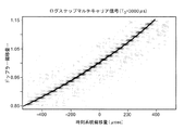
図2Aは基礎信号に係る整列位相ログステップマルチキャリア信号(初期時刻T0=3000μs)のプロファイル及び包絡線を示すグラフである。また、図2Bは比較例に係るログスイープチャープ信号のプロファイル及び包絡線を示すグラフである。さらに、図2Cは比較例に係る等間隔マルチキャリア信号のプロファイル及び包絡線を示すグラフである。 FIG. 2A is a graph showing a profile and an envelope of an aligned phase log step multicarrier signal (initial time T 0 = 3000 μs) related to a basic signal. FIG. 2B is a graph showing the profile and envelope of the log sweep chirp signal according to the comparative example. Furthermore, FIG. 2C is a graph showing the profile and envelope of an equally spaced multicarrier signal according to a comparative example.
他の変調方式、例えば周波数チャープ波では、周波数と位相は連続的に変化するため、プロファイルはドップラー偏移量ρ=1を中心に平坦な形状となる。また、OFDM(Orthogonal Frequency Divisional Multiplexing)信号では、キャリアが対数間隔をなさないため、プロファイル微細構造はρ=1付近に限定してわずかに見られるにとどまる。それ以外の領域ではキャリア周波数の干渉が乱雑に起こるため、プロファイルはρ=1の近傍で鋭いピークを構成するのみである(図2A、図2B及び図2C参照)。 In other modulation schemes, for example, frequency chirp waves, the frequency and phase change continuously, so the profile has a flat shape centered on the Doppler shift amount ρ = 1. In addition, in the OFDM (Orthogonal Frequency Divisional Multiplexing) signal, the carrier does not form a logarithmic interval, so that the profile fine structure is limited to the vicinity of ρ = 1 and is only slightly seen. Since the carrier frequency interference occurs randomly in other regions, the profile only forms a sharp peak in the vicinity of ρ = 1 (see FIGS. 2A, 2B, and 2C).
2.4 相互相関プロファイルの包絡線
相互相関プロファイルの極大値を繋げた包絡線を求めてみる。整列位相ログステップマルチキャリア信号の包絡線は、一致するキャリアの個数がドップラー偏移量に従って減少するため、ρ=1を頂点とする山形の三角形となる。加えてドップラー偏移は信号長にも影響を与えるため、包絡線はその影響も反映したものとなっている。
2.4 Cross-correlation profile envelope Let's find the envelope that connects the maximum values of the cross-correlation profile. The envelope of the aligned phase log step multicarrier signal is a triangular triangle with ρ = 1 as the apex because the number of matching carriers decreases according to the Doppler shift amount. In addition, since the Doppler shift also affects the signal length, the envelope reflects that effect.
整列位相ログステップマルチキャリア信号g(t)=gp,q(t,T0)の信号区間を[−T,T]とする。ρをドップラー偏移量とすると、|T0|≦Tの場合に、プロファイル関数λg(ρ)の包絡線は、次の関数Λg(ρ)で近似される。
The signal section of the aligned phase log step multicarrier signal g (t) = g p, q (t, T 0 ) is defined as [−T, T]. When Doppler shift amount [rho, |
2.5 初期時刻の変更とプロファイル包絡線への影響
ログステップマルチキャリア信号の有用な性質である微細構造やならだかに逓減する包絡線の出現は、各キャリアの初期位相がすべてそろうように、すなわち初期時刻T0=0に選んだとき、最も顕著に現れる。しかし、そのようにすると、全キャリアの位相のそろう時点で、時間波形の波高値に顕著なピークが生成する。これは一定の平均電力を送信するのに大きなピーク電力の送信を要すことになり、送信機の設計を困難にする。一方、|T0|>T(2Tはバースト長)にするとそのピークは現れなくなり、比較的良好なピーク対平均比を実現できる。これは送信を容易にするが、ログステップマルチキャリア信号の利点を損なうものとなる。その利点を保つT0の限界を議論するため、次の関係式を求めることができる。
2.5 Change of initial time and effect on profile envelope The appearance of fine structure and gradually decreasing envelope, which are useful properties of log-step multi-carrier signals, so that all initial phases of each carrier are aligned, That is, it appears most prominently when the initial time T 0 = 0 is selected. However, when this is done, a significant peak is generated in the peak value of the time waveform when the phases of all the carriers are aligned. This requires transmission of a large peak power to transmit a certain average power, making the transmitter design difficult. On the other hand, when | T 0 |> T (2T is a burst length), the peak does not appear, and a relatively good peak-to-average ratio can be realized. This facilitates transmission but detracts from the advantages of log step multicarrier signals. In order to discuss the limit of T 0 that maintains its advantages, the following relational expression can be obtained.
整列位相ログステップマルチキャリア信号g(t)=gp,q(t,T0)の信号区間を[−T,T]とする。ρをドップラー偏移量とすると、初期時刻|T0|>Tの場合に、相互相関プロファイルλg(ρ)の包絡線は近似的に次の関数Λg(ρ)は次式で表される。 The signal section of the aligned phase log step multicarrier signal g (t) = g p, q (t, T 0 ) is defined as [−T, T]. When ρ is the Doppler shift amount, when the initial time | T 0 |> T, the envelope of the cross-correlation profile λ g (ρ) is approximately expressed by the following function Λ g (ρ): The
ここで、式(10)と式(11)の違いは、送信信号と受信信号の位相の一致する重複区間の変化によるものである。 Here, the difference between the formula (10) and the formula (11) is due to a change in the overlapping section in which the phases of the transmission signal and the reception signal coincide.
図3は整列位相ログステップマルチキャリア信号の包絡線関数における初期時刻T0の変化による影響を示すグラフである。図3に示すように、プロファイル包絡線が比較的なだらかに変化する現象は初期時刻|T0|を時刻原点からずらしても、良く保たれる。しかし、限界を超えて初期時刻|T0|を大きくすると、プロファイル包絡線の変化は急峻なものになり、やがてピークの繰り返しは見られなくなる。 FIG. 3 is a graph showing the influence of a change in the initial time T 0 on the envelope function of the aligned phase log step multicarrier signal. As shown in FIG. 3, the phenomenon in which the profile envelope changes relatively gently is well maintained even when the initial time | T 0 | is shifted from the time origin. However, if the initial time | T 0 | is increased beyond the limit, the change in the profile envelope becomes steep, and the repetition of the peak is not observed.
2.6 ピーク時刻の系統偏移
図4はログステップマルチキャリア信号(初期時刻T0=3000μs)のドップラー偏移による系統偏移を示すグラフである。図4に示すように、整列位相ログステップマルチキャリア信号の初期時刻T0を0以外の値に設定すると、相互相関のピークを与える時刻に系統偏移が現れる。初期時刻T0<0を与えると、相互相関ピーク時刻は反射物体が近づく場合により早く現れるようになり、一方初期時刻をT0>0とすると、反射物体が近づく場合により遅く現れる。これは反射波を画像化したとき、物体の検出位置の誤差となるため、厳密に議論しておく必要がある。その誤差(偏移)は次式により求められる。ドップラー偏移量をρとしたとき、整列位相ログステップマルチキャリア信号g(t)=gp,q(t,T0)の相互相関<g|Dρg>(t)は、次の時刻t0=γg(ρ)にピークを持つ。ここで、T0=3000μsである。
2.6 System Deviation at Peak Time FIG. 4 is a graph showing the system deviation due to the Doppler deviation of the log step multicarrier signal (initial time T 0 = 3000 μs). As shown in FIG. 4, when the initial time T 0 of the aligned phase log step multicarrier signal is set to a value other than 0, a system shift appears at the time when the cross correlation peak is given. When the initial time T 0 <0 is given, the cross-correlation peak time appears earlier when the reflecting object approaches, whereas when the initial time T 0 > 0, it appears later when the reflecting object approaches. This is an error in the detection position of the object when the reflected wave is imaged, so it must be strictly discussed. The error (deviation) is obtained by the following equation. When the Doppler shift amount is ρ, the cross-correlation <g | D ρ g> (t) of the aligned phase log step multicarrier signal g (t) = g p, q (t, T 0 ) It has a peak at t 0 = γ g (ρ). Here, T 0 = 3000 μs.
この現象は、図2Bのログスイープチャープ波にも見られるものであるが、ログスイープチャープ波の場合には、波形の合致する時刻がドップラー偏移によって変化することが原因であるのに対して、ログステップマルチキャリア信号の場合には、周波数の一致するキャリアの同一時刻における位相が系統的にずれることにより偏移が引き起こされる。式(12)によって、移動物体の検出位置の誤差を厳密に補正できる。 This phenomenon is also seen in the log sweep chirp wave of FIG. 2B, but in the case of the log sweep chirp wave, the cause is that the time at which the waveforms match changes due to the Doppler shift. In the case of a log step multi-carrier signal, a shift is caused by systematically shifting the phases of carriers having the same frequency at the same time. The error in the detection position of the moving object can be strictly corrected by Expression (12).
2.7 本実施形態が解決しようとする課題
次いで、本発明に係る実施形態において解決すべき課題及び解決方法について以下に説明する。
2.7 Problems to be Solved by the Present Embodiment Next, problems to be solved and solutions in the embodiment according to the present invention will be described below.
計測精度を改善するには受信信号のSN比を向上させることが基本となる。ドップラーイメージングシステムはレーダー技術の一分野であるが、電波レーダー装置において、SN比を向上させる手法にパルス圧縮技術がある。これは検出波形として従来のインパルスではなく、持続波(バースト波)を使うものである。パルス波に比べバースト波は、同じ波高値でも相対的に大きなエネルギーをもつ。そのため信号の平均電力を、インパルスに比べ大きくとることができ、SN比の向上を達成できる。反面、信号の時間位置が不正確となるため、受信検波には通常の包絡線検波ではなく、送信信号形を参照信号にした相関処理により行う。この処理により特定の受信時刻に相関ピークが得られ、ちょうどインパルスを検出したのと同様の結果となるため、相関でバーストをパルスに圧縮したようにみなし、「パルス圧縮」と呼ばれる。 In order to improve the measurement accuracy, it is fundamental to improve the SN ratio of the received signal. The Doppler imaging system is a field of radar technology, and there is a pulse compression technology as a technique for improving the SN ratio in a radio wave radar device. This uses a continuous wave (burst wave) instead of a conventional impulse as a detection waveform. Compared to a pulse wave, a burst wave has relatively large energy even at the same peak value. Therefore, the average power of the signal can be made larger than that of the impulse, and an improvement in the SN ratio can be achieved. On the other hand, since the time position of the signal becomes inaccurate, reception detection is performed not by normal envelope detection but by correlation processing using the transmission signal form as a reference signal. By this processing, a correlation peak is obtained at a specific reception time, and the result is the same as when an impulse is detected. Therefore, it is considered that a burst is compressed into a pulse by correlation and is called “pulse compression”.
パルス圧縮の結果どれだけ精密に物体の距離情報を得られるか、すなわち相関出力がどれだけ尖鋭なパルスとなるかは、使用する信号の周波数帯域幅に依存している。パルス幅τと帯域幅Bはτ=1/Bの関係にある。そのためパルス圧縮には、検出の目的精度に対して十分な帯域幅をもつ信号波形を用意しなければならない。 How precisely the object distance information can be obtained as a result of pulse compression, that is, how sharp the correlation output is, depends on the frequency bandwidth of the signal used. The pulse width τ and the bandwidth B have a relationship of τ = 1 / B. Therefore, for pulse compression, a signal waveform having a sufficient bandwidth for the target accuracy of detection must be prepared.
一方で、パルス圧縮の欠点は、移動物体の検出が困難となることである。移動物体からの反射波はドップラー偏移による変形を受けるが、これは受信機の相関処理段階で、参照信号(送信信号)とは違ったものになっていることを意味する。そのためパルス圧縮によると、移動物体は誤った位置に検出されたり、ぼやけて検出されたり、そもそも検出されなかったりする。画像のSN比を向上できるパルス圧縮技術は、ドップラーイメージングにも使用すべき手法であるが、この問題のため、まだ実施例は少ない。 On the other hand, a drawback of pulse compression is that it is difficult to detect moving objects. The reflected wave from the moving object undergoes deformation due to Doppler shift, which means that it is different from the reference signal (transmission signal) at the correlation processing stage of the receiver. Therefore, according to the pulse compression, the moving object is detected at a wrong position, detected in a blurred manner, or not detected at all. A pulse compression technique that can improve the S / N ratio of an image is a technique that should be used for Doppler imaging, but due to this problem, there are few examples.
パルス圧縮によっても、移動物体も比較的その影響なく検出できる、すなわち運動感受性の低い波形として、周波数チャープ波形が知られている。それを使用したパルス圧縮型ドップラーイメージングの報告がある(例えば、非特許文献1参照)。しかし波形の運動感受性が低い場合は、検出される速度の精度を犠牲にしがちである。逆に最も速度感受性の高い波形を使用して、特定速度の物体のみ検出する発明もある(例えば、特許文献1参照)。しかし視野内のさまざまな速度をもつ物体分布を描出するには、検出計算をさまざまな速度について繰り返す必要があり、処理速度を犠牲としている。パルス圧縮に立脚しつつ、広い速度範囲の物体を、精度よく、かつ少ない計算量で検出できるドップラーイメージング技術が望まれる。 A frequency chirp waveform is known as a waveform that can detect a moving object relatively without being affected by the pulse compression, that is, has a low motion sensitivity. There is a report of pulse compression type Doppler imaging using the same (for example, see Non-Patent Document 1). However, when the motion sensitivity of the waveform is low, the accuracy of the detected speed tends to be sacrificed. On the other hand, there is also an invention in which only a specific speed object is detected using a waveform having the highest speed sensitivity (see, for example, Patent Document 1). However, to depict the distribution of objects with different velocities in the field of view, it is necessary to repeat the detection calculation for different velocities, at the expense of processing speed. A Doppler imaging technique that can detect an object in a wide speed range with high accuracy and a small amount of calculation while being based on pulse compression is desired.
周波数チャープ信号は波形の周期が連続的に変化しており、ドップラー偏移で波形が伸び縮みしても、送信信号形と受信信号形でどこかに形状のほぼ一致する領域があり、動く物体を検出できる。しかしその一致は波形の比較的限られた局所であったり、また原波形とはずれた位置であったりして、検出の速度精度や位置精度に限界がある。 The frequency chirp signal has a continuously changing waveform period, and even if the waveform expands or contracts due to Doppler shift, there is a region where the shape of the transmitted signal shape and the received signal shape are almost the same. It can be detected. However, the coincidence is at a relatively limited local area of the waveform or at a position deviated from the original waveform, and there is a limit in detection speed accuracy or position accuracy.
特許文献1では、計測に必要な周波数帯域の信号を、周波数が等間隔で分布した複数周波数信号として合成し使用することで、鋭敏な位置検出性能と、鋭敏な速度検出性能を得ている。しかし広範囲の速度について画像を計算しようとすると演算量が膨大となる。
In
ある帯域をもつ信号にドップラー偏移が加わり、例えば周波数が10%上昇した場合、1kHzの周波数の信号成分は1.1kHzに上昇する。また10kHzの周波数の信号成分は11kHzに上昇する。低い周波数成分の周波数上昇は0.1kHzで、高い周波数成分の周波数上昇は1kHzとなるように、高い周波数ほど大きな変移を受ける。すなわちドップラー偏移は加算でなく、乗算で効果を及ぼす。 When a Doppler shift is added to a signal having a certain band and, for example, the frequency is increased by 10%, the signal component of the frequency of 1 kHz is increased to 1.1 kHz. The signal component with a frequency of 10 kHz rises to 11 kHz. The higher frequency is subjected to a larger transition so that the frequency increase of the low frequency component is 0.1 kHz and the frequency increase of the high frequency component is 1 kHz. That is, the Doppler shift has an effect not by addition but by multiplication.
周波数を等間隔にとった複合周波数信号は、ドップラー偏移後の周波数成分は等間隔でなくなり、原波形との一致を失う。これが、特許文献1の波形が鋭敏な速度感受性を持った理由である。そこで、周波数間隔を指数関数で配置した、次の複合周波数波形を考える。ここで、時間t=0ではすべての周波数成分の位相が揃っているものと仮定する。
In the composite frequency signal having the same frequency, the frequency components after the Doppler shift are not evenly spaced, and lose the coincidence with the original waveform. This is the reason why the waveform of
ここで、式(13)は式(6)の実数部を取り出したものであり、一例としてp=2,q=54,f0=28.6kHz,ak=1,φk=0に選ぶと、波形は図5のようになる。図5は比較例に係るログステップマルチキャリア信号の信号波形を示す波形図である。 Here, Expression (13) is obtained by extracting the real part of Expression (6). As an example, p = 2, q = 54, f 0 = 28.6 kHz, a k = 1, and φ k = 0 are selected. The waveform is as shown in FIG. FIG. 5 is a waveform diagram showing a signal waveform of a log step multicarrier signal according to a comparative example.
式(22)の信号波形はドップラー偏移つまり乗算による周波数偏移を受けても、周波数間隔が指数関数的であるという性質は保持され、周波数チャープ波形と同様に、ドップラー偏移を受けても相関一致性は維持される。また、特許文献1の波形とも類似することから、高い位置検出性能、速度検出性能をもつと期待される。指数的な周波数間隔は、ログすなわち対数的に表示すると等間隔となるため、この複合周波数波形をログステップマルチキャリア信号と呼ぶ。この波形を使うイメージング方式の議論は例えば非特許文献3に示されている。
Even if the signal waveform of Expression (22) is subjected to Doppler deviation, that is, frequency deviation due to multiplication, the property that the frequency interval is exponential is maintained, and similarly to the frequency chirp waveform, it is subject to Doppler deviation. Correlation consistency is maintained. Moreover, since it is similar to the waveform of
式(22)の波形は、時刻t=0で非常に大きな値をとり、またその周辺で逆に波高のない領域を生じて、レーダー装置やイメージング装置での使用に適さない。それは式(22)のパラメータの選び方に限らず、この形式の波形に概略共通に生ずる性質である。例えば、t=0を含む波形部分(送信電力が非常に大きな部分)を避け、比較的t=0に近い場所で波高値がほぼ一定となる領域、すなわち図5の矢印の時間期間Tsの範囲の信号をとり出して使用して、これを「整列位相ログステップマルチキャリア信号」と呼ぶことができる。なお、非特許文献3においては、時間t=0ではすべての周波数成分の位相が揃っている所定の初期位相を有するものを「整列位相ログステップマルチキャリア信号」としているが、t=0を含む波形部分を避け、比較的t=0に近い場所で波高値がほぼ一定となる領域、すなわち図5の矢印の時間期間Tsの範囲の信号をとり出して使用することまでは開示していない。
The waveform of Equation (22) takes a very large value at time t = 0, and generates a region having no wave height in the vicinity thereof, which is not suitable for use in a radar device or an imaging device. This is not limited to the method of selecting the parameter of the equation (22), but is a property that occurs generally in common in this type of waveform. For example, a waveform portion including t = 0 (portion where transmission power is very large) is avoided, and a region where the peak value is substantially constant at a location relatively close to t = 0, that is, a range of the time period Ts indicated by the arrow in FIG. This signal can be extracted and used, and can be called an “aligned phase log step multicarrier signal”. In
整列位相ログステップマルチキャリア信号は広い速度領域の物体を容易に検出でき(低い速度依存性)、しかし速度検出精度は高い(高い速度依存性)という、すぐれた性質を持つ。しかし、欠点として非特許文献3に示されているとおり、それは移動物体を誤った位置に検出してしまう。それを解決しないと、高精度なドップラーイメージングに使用できる波形にならない。
The aligned phase log step multi-carrier signal has an excellent property that an object in a wide speed region can be easily detected (low speed dependence), but the speed detection accuracy is high (high speed dependence). However, as shown in
2.8 改善されたログステップマルチキャリア信号
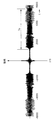
図6は本実施形態に係る対称整列位相ログステップマルチキャリア信号の信号波形を示す波形図である。
2.8 Improved Log Step Multi-Carrier Signal FIG. 6 is a waveform diagram showing signal waveforms of a symmetrically aligned phase log step multi-carrier signal according to this embodiment.
基礎信号であるログステップマルチキャリア信号を一対として用い、図6のように一方の時間順序を逆(前後逆向き)にし、当該1対のログステップマルチキャリア信号を連結して合成した信号波形を考える。一対の連結合成した信号波形は原点の軸に対し対称となるよう配置してもよく、あるいは点対称となるよう、さらに一方の極性を反転させて使用してもよい。両者は時間軸上に離して配置してもよく、図6のごとく接して配置してもよく、あるいは一部ないし全部を重畳させて配置してもよい。なお、重畳部は両者の波高の和をとるものとする。 A log step multi-carrier signal that is a basic signal is used as a pair, and a signal waveform obtained by combining one pair of log step multi-carrier signals by reversing one time sequence (reverse and backward) as shown in FIG. Think. A pair of connected and synthesized signal waveforms may be arranged so as to be symmetric with respect to the axis of the origin, or may be used with one polarity reversed so as to be point-symmetric. Both may be arranged apart from each other on the time axis, may be arranged so as to contact each other as shown in FIG. In addition, a superimposition part shall take the sum of both wave heights.
結果として図6の信号波形は、指数関数的間隔をもつ複数周波数成分からなる複合波すなわちログステップマルチキャリア信号であり、波形の時間中点(t=0)において左右線対称すなわち偶関数、あるいは左右点対称(奇関数)となる。これを「対称ログステップマルチキャリア信号」と呼ぶ。対称ログステップマルチキャリア信号をドップラーレーダー装置やドップラーイメージング装置に使用すると、非特許文献3の波形が移動物体について検出位置を誤った欠点を解消し、移動物体の速度を高精度に検出でき、かつ移動物体についても検出位置を誤らないという効果を有する。
As a result, the signal waveform of FIG. 6 is a composite wave composed of a plurality of frequency components having exponential intervals, that is, a log step multicarrier signal, and is symmetrical with respect to left and right lines, that is, an even function at the time midpoint (t = 0) of the waveform. Left / right point symmetry (odd function). This is called a “symmetric log step multicarrier signal”. When the symmetrical log step multi-carrier signal is used in a Doppler radar device or a Doppler imaging device, the waveform of
さらに、図5のt=0の近傍でかつ波高値が概略一定となった領域、すなわち非特許文献3の整列位相ログステップマルチキャリア信号を前述のように配置し、線対称波形(偶関数)ないし点対称波形(奇関数)とすることができる。これを「対称整列ログステップマルチキャリア信号」とよぶ。「対称整列ログステップマルチキャリア信号」を使用すると、広い速度範囲の移動物体検出でき、高い速度精度で速度検出でき、かつ移動物体についても検出位置を誤らないという効果を有する。なお、「対称整列マルチキャリア信号」の相関ピークがドップラー偏移に影響されない証明については、当該明細書の最後部の付録で記載した。また、t=0で波高値が非常に高い領域は詳細後述するように除去することが好ましい。
Further, in the vicinity of t = 0 in FIG. 5 and the region where the crest value is substantially constant, that is, the aligned phase log step multicarrier signal of
以上説明したように、対称ログステップマルチキャリア信号、ないし対称整列ログステップマルチキャリア信号を使用することで、その性質を生かしつつ、効率的な処理方式によるドップラーイメージング装置を構成することができる。 As described above, by using a symmetric log step multicarrier signal or a symmetric aligned log step multicarrier signal, it is possible to configure a Doppler imaging apparatus using an efficient processing method while taking advantage of its characteristics.
2.9 イメージング手法
パルス圧縮では、参照信号(送信信号)と受信信号の間で相関演算をすることで、反射波の鋭いピークを再構成する。しかし受信信号はドップラー偏移の影響を受けているため、ドップラー偏移量によっては、プロファイル微細構造の影響で、相関関数ピークが減少し、あるいはまったく得られない場合がある。そこで、プロファイルの微細構造の間を埋めるため、あらかじめ周波数シフトさせた参照信号を複数用意し、それらとの相関計算を行うことによって、これを補うことにする。送信信号gp,q(t,T0)からわずかに周波数をシフトさせた次式の3種の参照信号を用意する。
2.9 Imaging Method In pulse compression, a sharp peak of a reflected wave is reconstructed by performing a correlation operation between a reference signal (transmission signal) and a reception signal. However, since the received signal is affected by the Doppler shift, the correlation function peak may be reduced or not obtained at all due to the influence of the profile fine structure depending on the Doppler shift amount. Therefore, in order to fill the gap between the fine structures of the profile, a plurality of reference signals whose frequencies are shifted in advance are prepared, and this is compensated by calculating correlation with them. Three kinds of reference signals of the following formulas are prepared by slightly shifting the frequency from the transmission signal g p, q (t, T 0 ).
これらの参照信号を用いて受信信号s(t)との間にそれぞれ相互相関係数の演算(相関演算)を適用する。 Using these reference signals, the calculation of the cross-correlation coefficient (correlation calculation) is applied to the received signal s (t).
![]()
![]()
図13を参照して詳細後述するように、R、G、Bは検出波の周波数がわずかに低くなった状態、高くなった状態などを移動する光源の赤方偏移、青方偏移になぞらえたもので、実際の色に対応しているわけではない。 As will be described in detail later with reference to FIG. 13, R, G, and B are the red shift and blue shift of the light source that moves in a state where the frequency of the detection wave is slightly lowered or raised, for example. It's like a comparison, it doesn't correspond to an actual color.
こうして得られた相互相関係数X(t)=(XR,XG,XR)(t)を時刻tにおける赤、緑、青の輝度として用いてイメージング(画像化)を行う。系統偏移の式(12)の影響で同一反射物体に対する複数の参照信号によるピーク値は異なる時刻に現れることがある。しかし、その移動差も決定できるため補正できる。 Imaging is performed using the cross-correlation coefficient X (t) = (X R , X G , X R ) (t) obtained in this way as red, green, and blue luminances at time t. Due to the influence of the system deviation equation (12), peak values due to a plurality of reference signals for the same reflecting object may appear at different times. However, since the movement difference can be determined, it can be corrected.
2.10 ドップラー偏移量概算推定
詳細後述するドップラー偏移量推定では、それに先立ってドップラー偏移量の概算値を知ることが必要になる。ドップラー偏移量の概算値は例えば次式のように求める。しきい値Hを適当に定め、受信信号s(t)のフーリエ変換Fs(f)からスペクトルの上限値f1と下限値f2を得る。
2.10 Approximate Doppler Deviation Estimation In detail, Doppler deviation estimation described in detail later requires an estimate of the approximate Doppler deviation. The approximate value of the Doppler shift amount is obtained, for example, as follows. The threshold value H is appropriately determined, and the upper limit value f 1 and the lower limit value f 2 of the spectrum are obtained from the Fourier transform Fs (f) of the received signal s (t).
![]()
![]()
![]()
![]()
ここで、f0を送信信号に用いるログステップマルチキャリア信号の基本周波数とし、ドップラー偏移量概算値ρ0を次式により求める。 Here, f 0 is the fundamental frequency of the log step multicarrier signal used for the transmission signal, and an approximate Doppler shift amount ρ 0 is obtained by the following equation.
スペクトルの上下限値を用いるこの方法は、直接のノイズの影響を受けやすいため改善の余地がある。より概算推定値のノイズ耐性を向上させるためには、例えば送信信号のスペクトル形を調整して上下限にピークを持つように各キャリア信号の振幅を変化させる等の工夫が可能である。 Since this method using the upper and lower limits of the spectrum is susceptible to direct noise, there is room for improvement. In order to further improve the noise tolerance of the approximate estimated value, for example, it is possible to devise such as adjusting the spectrum shape of the transmission signal and changing the amplitude of each carrier signal so as to have a peak at the upper and lower limits.
2.11 ドップラー偏移量精密推定
ドップラー偏移量はパルス圧縮の適用の結果得られたピーク値x=(xR,xG,xB)を用いて推定する。
2.11 Doppler Deviation Precise Estimation Doppler deviation is estimated using the peak value x = (x R , x G , x B ) obtained as a result of applying pulse compression.
![]()
![]()
ドップラー偏移量を推定するために、あらかじめ理想的な条件の下で構築された辞書を準備する。相互相関関数M(ρ,t)=(MB,MG,MR)(ρ,t)は参照信号をg(t)=gp,q(t,T0)として、次の計算により求める。 In order to estimate the Doppler shift amount, a dictionary constructed in advance under ideal conditions is prepared. The cross-correlation function M (ρ, t) = (M B , M G , M R ) (ρ, t) is obtained by the following calculation using the reference signal as g (t) = g p, q (t, T 0 ). Ask.
![]()
![]()
ドップラー偏移量ρに従って決まるピーク値を抽出して辞書m(ρ)=(mR,mG,mB)(ρ)を構成する。 A peak value determined according to the Doppler shift amount ρ is extracted to construct a dictionary m (ρ) = (m R , m G , m B ) (ρ).
![]()
![]()
辞書m(ρ)を用いて観測値xからρを推定する問題は、方程式x=m(ρ)をρに関して解くのと等価である。しかし、辞書m(ρ)は周期性のために多値となり、このままでは逆関数m−1を求めることができない。逆関数m−1を求めるため、ピーク値に基づく比mB(ρ)/mG(ρ)、mR(ρ)/mB(ρ)又はmG(ρ)/mR(ρ)のいずれかが単調増加となる区間を選び、この範囲内で推定を行う。そこでドップラー偏移量とピーク比を関連付ける関数Ψ(ρ)を次のように定義する。 The problem of estimating ρ from observation x using dictionary m (ρ) is equivalent to solving equation x = m (ρ) with respect to ρ. However, the dictionary m (ρ) is multivalued due to periodicity, and the inverse function m−1 cannot be obtained as it is. In order to obtain the inverse function m-1, the ratio m B (ρ) / m G (ρ), m R (ρ) / m B (ρ) or m G (ρ) / m R (ρ) based on the peak value Choose a section that either increases monotonically, and estimate within this range. Therefore, a function Ψ (ρ) that associates the Doppler shift amount with the peak ratio is defined as follows.
図7は整列位相ログステップマルチキャリア信号のドップラー偏移量とピーク比とを関連づける関数Ψ(ρ)が区分的単調増加関数を示すグラフである。図7に示すように、kを整数とするΨ(ρ)は区分的に単調増加関数となり、推定するρの属する区間を与えることによりρ=Ψ−1(ψ)を計算できる。ドップラー偏移量ρの概算推定値ρ’は上記の方法で得られているので、これにより単調増加区間を指定し、観測により得られた相互相関ピーク値のうち主要な2値を選んでΨ−1(ψ)を計算し、正確なρの推定値を得る。 FIG. 7 is a graph showing a piecewise monotonically increasing function Ψ (ρ) that correlates the Doppler shift amount and the peak ratio of the aligned phase log step multicarrier signal. As shown in FIG. 7, Ψ (ρ), where k is an integer, is a piecewise monotonically increasing function, and ρ = Ψ −1 (ψ) can be calculated by giving a section to which ρ to be estimated belongs. Since the approximate estimated value ρ ′ of the Doppler shift amount ρ is obtained by the above method, a monotonically increasing section is designated by this, and two main correlation correlation peak values obtained by observation are selected and Ψ −1 (ψ) is calculated to obtain an accurate estimate of ρ.
図8はカラードップラー法で用いるドップラー位相関数を示すグラフである。上記の提案手法においてイメージング結果からドップラー量を得るための方法について考察したが、その一方でカラードップラー法についてはイメージング結果からドップラー量を計算するための明示的方法が与えられていない。すなわち、カラードップラー法で得られる情報はドップラー位相φであり、これを用いてドップラー量ρを計算する方法を与える必要がある。 FIG. 8 is a graph showing a Doppler phase function used in the color Doppler method. In the above proposed method, the method for obtaining the Doppler amount from the imaging result has been considered. On the other hand, for the color Doppler method, an explicit method for calculating the Doppler amount from the imaging result is not given. That is, the information obtained by the color Doppler method is the Doppler phase φ, and it is necessary to provide a method for calculating the Doppler amount ρ using this information.
例えば、カラードップラー法のパルス波をg(t)=exp(jω1t)exp(jω0t)とすると、理論的には包絡線位相は(ρ−1)T1ω1と検出される。ところが実際にはパルス波の両端がスペクトルに及ぼす影響と実装されたヒルベルト変換器の持つ周波数特性の影響で系統的な誤差が生じる。その誤差の影響を相殺するため、我々は、あらかじめノイズのない設定でドップラー量ρを変化させながら計算を行い、得られるドップラー位相φを記録することによって辞書を作成した。こうして得られた辞書Φは、ドップラー量ρに位相φを対応させる関数である(図8)。 For example, if the pulse wave of the color Doppler method is g (t) = exp (jω 1 t) exp (jω 0 t), the envelope phase is theoretically detected as (ρ−1) T 1 ω 1. . However, in reality, systematic errors occur due to the influence of both ends of the pulse wave on the spectrum and the frequency characteristics of the mounted Hilbert transformer. In order to cancel out the influence of the error, we made a dictionary by performing calculation while changing the Doppler amount ρ in a noise-free setting in advance and recording the obtained Doppler phase φ. The dictionary Φ thus obtained is a function that associates the phase φ with the Doppler amount ρ (FIG. 8).
この関数Φは、カラードップラー法の包絡線関数が値を持つ区間において単調増加な連続関数であり、この区間における逆関数の存在により辞書の逆引きが可能となる。これにより検出された位相からドップラー量ρ=Φ−1(φ)を推定した。パルス幅を超えてドップラー偏移の影響があるときには、包絡線関数の自己相関関数は0となり、位相の検出ができなくなる。そのためカラードップラー法の検出範囲は自己相関関数が値を持つ範囲に限定される。 This function Φ is a monotonically increasing continuous function in a section where the envelope function of the color Doppler method has a value, and the reverse lookup of the dictionary is possible due to the presence of the inverse function in this section. The Doppler amount ρ = Φ −1 (φ) was estimated from the detected phase. When there is an influence of Doppler shift beyond the pulse width, the autocorrelation function of the envelope function becomes 0 and the phase cannot be detected. Therefore, the detection range of the color Doppler method is limited to a range in which the autocorrelation function has a value.
3.ドップラーイメージングシステム
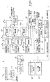
図10は本発明の一実施形態に係るドップラーイメージングシステムの構成を示すブロック図である。また、図11Aは図10のドップラーイメージング信号送信装置1の構成を示すブロック図であり、図11Bは図11Aの変形例であるドップラーイメージング信号送信装置1Aの構成を示すブロック図である。さらに、図12は図10のドップラーイメージング信号受信装置2の構成を示すブロック図である。
3. Doppler Imaging System FIG. 10 is a block diagram showing a configuration of a Doppler imaging system according to an embodiment of the present invention. 11A is a block diagram showing a configuration of the Doppler imaging
対称ログステップマルチキャリア信号、あるいは対称整列ログステップマルチキャリア信号を使用したドップラーイメージング装置について、図10〜図12を参照して、動作確認実験で使用した空中超音波を用いたレーダー装置に基づき以下説明する。これは雑踏内でロボットを誘導するような用途を想定して構成されたものであるが、同様の原理で、波動として空中音波、水中音波、固体伝搬音波、電磁波、変調レーザー光を使用したドップラーイメージング装置も構成できる。 A Doppler imaging apparatus using a symmetric log step multicarrier signal or a symmetric aligned log step multicarrier signal is described below with reference to FIGS. 10 to 12 based on a radar apparatus using an aerial ultrasonic wave used in an operation confirmation experiment. explain. This is designed for the purpose of guiding a robot in a crowd, but with the same principle, Doppler uses aerial sound waves, underwater sound waves, solid-propagating sound waves, electromagnetic waves, and modulated laser light as waves. An imaging device can also be constructed.
単スペクトルの探索信号を用いるレーダーにおいて、接近する物体によって反射された反射波の周波数はドップラー効果により上昇し、後退する物体により反射された反射波の周波数はドップラー効果により降下する。もとの周波数をfとした場合、ドップラー偏移後の周波数f’は次式(式(1)の再掲)で表される。 In a radar using a single spectrum search signal, the frequency of a reflected wave reflected by an approaching object rises due to the Doppler effect, and the frequency of the reflected wave reflected by a receding object drops due to the Doppler effect. Assuming that the original frequency is f, the frequency f ′ after the Doppler shift is expressed by the following equation (representation of equation (1)).
![]()
![]()
ここでρはドップラー偏移量を表す係数で、反射物体のレンジ速度成分(接近方向を正にとる)をv、音速をcとすると次式を得る。 Here, ρ is a coefficient representing the amount of Doppler shift, and the following equation is obtained when the range velocity component (the approach direction is positive) of the reflecting object is v and the sound velocity is c.
![]()
![]()
反射波の周波数偏移を観測し、この関係を逆算して物体の速度vを求める。すなわち、次式を用いて速度vを求めることができる。 The frequency shift of the reflected wave is observed, and this relationship is calculated backward to obtain the velocity v of the object. That is, the speed v can be obtained using the following equation.
対称整列ログステップマルチキャリア信号を探索信号としたレーダー装置でも、移動物体からの反射波のスペクトルは同様のドップラー偏移を受けるが、送信信号形を参照信号にして相関処理により信号検出するので、ドップラー偏移は相関出力の変化として観測される。 Even in a radar device that uses a symmetrical aligned log step multicarrier signal as a search signal, the spectrum of the reflected wave from the moving object undergoes the same Doppler shift, but the signal is detected by correlation processing with the transmission signal form as the reference signal. The Doppler shift is observed as a change in the correlation output.
図9は本実施形態に係る線対称の整列位相ログステップマルチキャリア信号のプロファイル及び包絡線を示すグラフである。すなわち、図9において、各種のドップラー偏移係数のかかった場合の相関出力の変化をグラフで示す。これをプロファイルという。ドップラー偏移量ρの変化にともないプロファイル外形はλ字型の包絡線(エンベロープという)をもち、その内部で急速な変動(微細構造という)を示す。ドップラー偏移量ρの変化にあまり影響されない、なだらかなエンベロープと、その変化に敏感に反応する微細構造をあわせもつことが対称整列ログステップマルチキャリア信号(ないし整列位相ログステップマルチキャリア信号)の特徴で、ほかの波形には見られないものである。 FIG. 9 is a graph showing the profile and envelope of the line-symmetric aligned phase log step multicarrier signal according to the present embodiment. That is, FIG. 9 is a graph showing changes in correlation output when various Doppler shift coefficients are applied. This is called a profile. The profile profile has a λ-shaped envelope (referred to as an envelope) with a change in the Doppler shift amount ρ, and shows a rapid fluctuation (referred to as a fine structure) inside thereof. A characteristic of symmetrically aligned log step multicarrier signal (or aligned phase log step multicarrier signal) is that it has a gentle envelope that is not significantly affected by changes in Doppler deviation ρ and a fine structure that reacts sensitively to the change. This is not seen in other waveforms.
対称整列ログステップマルチキャリア信号を使用したドップラーイメージングとは、このエンベロープおよび微細構造に立脚した速度推定アルゴリズムを使用することである。それには、ドップラー偏移により微細構造の周期で数えて何周期分、検出ピークがずれたかの算出すなわち概算推定と、一山の微細構造に注目してその周期内での速度検出を行う詳細推定があり、両者の合算で広範囲で精密なドップラー偏移量ρの値の推定すなわち速度推定を行う。 Doppler imaging using symmetrically aligned log step multicarrier signals is to use a velocity estimation algorithm based on this envelope and fine structure. For this purpose, calculation of how many periods the detection peak has shifted by counting the period of the fine structure due to Doppler shift, that is, rough estimation, and detailed estimation that detects the speed within the period focusing on the fine structure of a mountain. Yes, the sum of the two estimates the value of the Doppler shift amount ρ in a wide range and precisely, that is, the speed estimation.
図10において、本実施形態にかかるドップラーイメージングシステムは、ドップラーイメージング信号送信装置1と、ドップラーイメージング信号受信装置2と、タイミングコントローラ10とを備えて構成される。ここで、ドップラーイメージング信号送信装置1は超音波スピーカ3を備え、探査信号波形を音波として空中に照射する。ドップラーイメージング信号受信装置2はマイクロホンアレイ4及び表示装置5を備え、検出対象の反射物体6からの反射波を受信するとともに、マイクロホンアレイ4のビームフォーミングによる信号処理により、その到来方向を決定し、空間分解能を得る。検出結果の位置情報、速度情報を表示装置5に表示する。全体の動作タイミングはタイミングコントローラ10からのタイミング信号により制御される。ここで、外界を1秒おきにイメージングする場合、タイミングコントローラ10は1秒おきの起動信号をドップラーイメージング信号送信装置1及びドップラーイメージング信号受信装置2に送出し、それが表示のリフレッシュ周期となる。
In FIG. 10, the Doppler imaging system according to this embodiment includes a Doppler imaging
図11Aにおいて、ドップラーイメージング信号送信装置1は、読み出し専用メモリ(ROM)11Rを有する送信信号発生器11と、D/A変換器12と、信号増幅器13と、超音波スピーカ3とを備えて構成される。送信信号発生器11は、タイミングコントローラ10からの起動信号を受けると、あらかじめ用意された対称ログステップマルチキャリア信号又は対称整列ログステップマルチキャリア信号の送信信号波形データを読み出し専用メモリ(ROM)11Rから読み出してD/A変換器12に出力する。D/A変換器12は、入力される送信信号波形データをA/D変換してアナログの送信信号を発生して信号増幅器13を介して超音波スピーカ3に出力して、当該送信信号は超音波スピーカ3から放射される。検出対象の反射物体6により最適な送信信号形に切り替えて使用する手法も可能で、この場合はROM部に複数波形パターンを格納しておくか、あるいは送信部内のマイクロプロセッサにより波形を計算生成、合成して使用することもできる。実験ではルネサスエレクトロニクス社SH2マイクロプロセッサを使用したマイクロプロセッサボードに16ビット1Mサンプル/sで信号波形を用意し、パイオニア社PT−R4スーパーツィータより図10の空中超音波波形を放射した。
In FIG. 11A, the Doppler imaging
図11Bの変形例において、ドップラーイメージング信号送信装置1Aは、読み出し専用メモリ(ROM)11Rを有する基礎信号発生器11Aと、信号処理回路14と、D/A変換器12と、信号増幅器13と、超音波スピーカ3とを備えて構成される。当該変形例では、基礎信号発生器11Aは基礎信号であるログステップマルチキャリア信号を発生し、信号処理回路14において、一対の基礎信号を発生したうえで、一方の基礎信号の時間順序を逆(前後逆向き)にし、合成して対称ログステップマルチキャリア信号又は対称整列ログステップマルチキャリア信号の送信信号波形データを生成してもよい。
11B, a Doppler imaging
図12において、ドップラーイメージング信号受信装置2は、マイクロホンアレイ4と、受信信号メモリ4mと、フーリエ変換器21と、ビームフォーミング回路22と、ビームフォーミングスキャン量設定器23と、レンジ量設定器24と、参照信号発生器31,41,51と、相関器32,42,52と、逆フーリエ変換器33,43,53と、位置検出信号発生器34と、読み出し専用メモリ(ROM)35Rを有する微細構造推定テーブル回路35と、窓関数信号発生器61と、遅延演算器62と、畳み込み演算器63と、送信スペクトルテンプレート信号発生器64と、信号比較器65とを備えて構成される。
In FIG. 12, the Doppler imaging
ドップラーイメージング信号受信装置2において、タイミングコントローラ10から起動信号を受けると、一定時間(最遠の物体からの反射波が到達するまでの間)、各マイクロホンアレイ4で受信信号を受信して受信信号メモリ4mに蓄積する。次いで、フーリエ変換器21は受信信号に対して高速フーリエ変換(FFT)により離散フーリエし、後続のビームフォーミング回路22に送る。実験ではKnowlesAcoustics社SPM0404UD5マイクロホン素子を横5.08mm,縦10.16mmピッチの16×8格子に配列した2次元マイクロホンアレイ4により受音し、各チャンネル信号を12ビット500kサンプル/sにA/D変換した後、FPGAによる信号処理ボードで処理した。
In the Doppler imaging
フーリエ変換器21により周波数領域に変換された受信信号は、ビームフォーミング回路22に送られる。ビームフォーミング回路22は、ビームフォーミングスキャン量設定器23からのビームフォーミングスキャン量に基づいて、各マイクロホンアレイ4の信号毎に、所定の時間遅延量と重み量を付け加えた後、全チャネルを加算し、上記スキャン量に対応する所定の範囲の空間の特定方向からの信号のみ抽出する操作を行う。ここで、受信信号は周波数領域に変換されているため、例えば時間遅延dを与える処理は複素数exp(−jd)を乗算することに対応する。実験では空間を縦横方向度103×53度について、100×40セクターに分割しビームフォーミングした。受信信号メモリ4mは最大128ms(レーダー距離として約20m)のデータを格納でき、それをFFT処理して使用した。
The received signal converted into the frequency domain by the
ビームフォーミング回路22により特定方向からの受信信号を取り出した後、それと参照信号との相関処理によって、パルス圧縮によってその方向の反射物体分布を得る。ここでは3通りの参照信号(周波数領域)、すなわち送信信号と同じ信号であって周波数領域にフーリエ変換した参照信号GG(f)、上記参照信号GG(f)を若干時間短縮した参照信号GB(f)、上記参照信号GG(f)を若干時間延長した参照信号GR(f)の3種を使用して行う。ここで、参照信号GB(f)は接近方向の運動のドップラー偏移で周波数の高くなった状態の送信信号に対応し、参照信号GR(f)は後退方向の運動のドップラー偏移で周波数の低くなった状態の送信信号に対応する。これら3種の参照信号は、微細構造の中心ピーク位置に着目して、図13のドップラー偏移量に相当する信号波形である。
After a received signal from a specific direction is extracted by the
本実施形態では、パルス圧縮すなわち物体位置検出の相関演算も周波数領域で行う。相関演算に使う参照信号形はあらかじめ離散フーリエ変換しておき、その複素共役と周波数領域の受信信号波形(ビームフォーマーにより特定方向からの信号に変換されたもの)を乗算する。これで相関波形のフーリエ変換が得られる。次にそれを離散逆フーリエ変換することで、ビームフォーミングスキャン量設定器23で設定されビームフォーミング回路22でスキャンされた空間方向について、距離(レンジ)軸方向の反射係数分布、すなわち反射物体の位置検出信号X{R,G,B}(t)を得る。
In the present embodiment, pulse compression, that is, correlation calculation for object position detection is also performed in the frequency domain. The reference signal form used for the correlation calculation is subjected to discrete Fourier transform in advance and multiplied by the complex conjugate and the received signal waveform in the frequency domain (converted into a signal from a specific direction by the beamformer). This provides a Fourier transform of the correlation waveform. Next, by performing discrete inverse Fourier transform, the reflection coefficient distribution in the distance (range) axis direction, that is, the position of the reflecting object is set in the spatial direction set by the beamforming scan
図12において、参照信号発生器31,41,51はそれぞれ参照信号GR(f)、参照信号GG(f)及び参照信号GB(f)を発生して相関器32,42,52に出力する。相関器32,42,52はそれぞれビームフォーミング回路22からの周波数領域の受信信号と、各参照信号GR(f),GG(f),GB(f)との相互相関係数信号XR(f),XG(f),XB(f)を演算して逆フーリエ変換器33,43,53に出力する。逆フーリエ変換器33,43,53はそれぞれ入力信号を時間領域の相互相関係数信号XR(t),XG(t),XB(t)に逆フーリエ変換して位置検出信号発生器34に出力する。
12, the
反射物体6の運動により参照信号GG(f)では、相互相関係数信号XG(f)が低くなる場合があるが、そのときは参照信号GB(f)を用いた相互相関係数信号XB(f)あるいは参照信号GR(f)を用いた相互相関係数信号XR(f)に強く反応している。よって、位置検出信号発生器34は総合的な位置検出信号X{R,G,B}(t)を次式を用いて計算する。
In some cases, the cross-correlation coefficient signal X G (f) may be low in the reference signal G G (f) due to the movement of the reflecting object 6. In this case, the cross-correlation coefficient using the reference signal G B (f) is used. It reacts strongly to the cross-correlation coefficient signal X R (f) using the signal X B (f) or the reference signal G R (f). Therefore, the position
![]()
![]()
これにより、各種の速度をもつ反射物体6について、もらすことなく検出できる。このレンジ(距離)方向の位置検出信号X{R,G,B}(t)は表示装置5に送られ、その方向の各距離について反射強度分布の描画を行う。すなわち、図12において、参照信号発生器31、41,51から相関器32,42,52及び逆フーリエ変換器33,43,53を介して位置検出信号発生器34までの信号処理部は位置検出部を構成する。
Thereby, it is possible to detect the reflecting object 6 having various speeds without giving it. The position detection signal X {R, G, B} (t) in the range (distance) direction is sent to the
速度検出もビームフォーミング回路22で選んだある空間方向に対し、そのレンジ(距離方向)軸各点について行う。また、速度検出は前述のように、微細構造のピーク単位で何単位ずれているか決める概算速度推定部60と、ひとつの微細構造の山の範囲内でのドップラー偏移量を決める詳細速度推定部(図12において、微細構造推定テーブル回路35で構成される)の2つの速度推定部からなる。
Speed detection is also performed for each point in the range (distance direction) axis in a certain spatial direction selected by the
概算速度推定部60においては、反射された受信信号を時間軸で表現すれば、各レンジ距離に相当する遅延時間の位置の信号を、そこを中心にした窓関数(ハン窓など)をかけることで取り出し、さらに高速フーリエ変換(FFT)をほどこす。するとそのレンジ距離の反射波のスペクトルが得られる。送信信号形のスペクトルは既知なので、それの周波数軸上での偏移量を求めると、概算推定になる。この実施形態ではあらかじめ受信信号形は周波数領域に変換されているので、周波数領域のみの演算を行うと都合がよい。窓関数のフーリエ変換の複素共役を求めておき、複素数関数exp(−jd)を乗じることで時間軸上で遅延量dだけ窓を移動させたのと等価のスペクトルを結果として得るので、あとは受信信号に畳み込み演算をしてやれば、時間軸の特定位置を切り出してフーリエ変換したものと相当の結果となる。そこから概算ドップラー推定量Cを得る。
In the approximate
図12において、概算速度推定部60は、窓関数信号発生器61と、遅延演算器62と、畳み込み演算器63と、送信スペクトルテンプレート信号発生器64と、信号比較器65とを備えて構成される。窓関数信号発生器61は、周波数領域の所定の窓関数信号を発生して遅延演算器62に出力する。遅延演算器62は、入力される窓関数信号に対してレンジ量設定器24により設定されるレンジ量(距離方向)に対応する時間軸上の遅延量dだけ遅延させた後、畳み込み演算器63に出力する。畳み込み演算器63は、遅延演算器62からの遅延された窓関数信号と、ビームフォーミング後の周波数領域の受信信号とを畳み込み演算を行って、演算結果の信号を信号比較器65に出力する。信号比較器65は、入力される畳み込み演算結果の信号を、送信スペクトルテンプレート信号発生器64からの周波数領域の送信信号と比較することにより、周波数軸上での偏移量を得ることにより概算速度推定量Cを演算して微細構造推定テーブル回路35に出力する。
In FIG. 12, the approximate
図14は図12のドップラーイメージング信号受信装置2内の概算速度推定部60の変形例である概算速度推定部60Aの構成を示すブロック図である。上記概算推定演算は局所的に時間領域で行うこともでき、図14のように概算推定処理を行ってもよい。図14において、変形例にかかる概算速度推定部60Aは、窓関数信号発生器61Aと、遅延演算器62Aと、乗算器63Aと、送信スペクトルテンプレート信号発生器64と、信号比較器65と、逆フーリエ変換器66と、フーリエ変換器67とを備えて構成される。窓関数信号発生器61Aは、時間領域の所定の窓関数信号を発生して遅延演算器62Aに出力する。遅延演算器62Aは、入力される窓関数信号に対してレンジ量設定器24により設定されるレンジ量(距離方向)に対応する時間軸上の遅延量dだけ遅延させた後、乗算器63Aに出力する。一方、ビームフォーミング後の周波数領域の受信信号は逆フーリエ変換器66により時間領域の受信信号に逆フーリエ変換された後、乗算器63Aに出力される。乗算器63Aは、遅延演算器62Aからの遅延された窓関数信号と、ビームフォーミング後の時間領域の受信信号とを乗算して、乗算結果の信号をフーリエ変換器67に出力する。フーリエ変換器67は入力される乗算結果の信号を周波数領域の信号に変換した後、信号比較器65に出力する。信号比較器65は、入力される乗算結果の信号を、送信スペクトルテンプレート信号発生器64からの周波数領域の送信信号と比較することにより、周波数軸上での偏移量を得ることにより概算速度推定量Cを演算して微細構造推定テーブル回路35に出力する。
FIG. 14 is a block diagram showing a configuration of an approximate
速度の詳細推定は、辞書のための読み出し専用メモリ(ROM)35Rを有する微細構造推定テーブル回路35により実行され、前述の概算速度推定量Cに、さらにレンジ位置のその点の反射強度である周波数領域の相互相関係数信号XR(f),XG(f),XB(f)を組み合わせた4次元量をインデックスとし、あらかじめ計算で求めておいた読み出し専用メモリ(ROM)35R内の詳細速度テーブルを検索することで、詳細速度推定量Fを得る。次いで、概算速度推定量Cに詳細速度推定量Fを加算した速度値に基づいて、式(24)を用いて精密なドップラー偏移量ρを演算し、当該演算された精密なドップラー偏移量ρに基づいて、式(25)を用いて物体速度vを演算する。演算された物体速度vを示す速度推定信号と、ビームフォーミングスキャン量設定器23からのビームフォーミングスキャン量及び距離方向のレンジ量設定器24からのレンジ量からなる表示座標信号とを表示装置5に送り、上述の位置検出信号X{R,G,B}(t)による物体配置図に速度分布図を重ねて表示させる。これにより、表示装置5において反射物体6の画像化を行うことができる。
Detailed estimation of the velocity is executed by the fine structure
以上の実施形態においては、ドップラーイメージング信号受信装置2における信号処理を、フーリエ変換にもとづく複素演算手法として説明した。この発明では探索信号波形に線対称(偶関数)ないし点対称(奇関数)を使用する。前者の場合、波形をフーリエ変換すると実数部のみの関数、後者の場合、波形をフーリエ変換すると虚数部のみの関数となる。したがって、上記で示した複素離散フーリエ変換によるドップラーイメージング演算は、前者は実数部のみ離散コサイン変換により求めた演算、ないし後者は虚数部のみ離散サイン変換でもとめた演算で行ってもよく、それにより計算コストを低下させることができる。
In the above embodiment, the signal processing in the Doppler imaging
以上の実施形態において、図12のドップラーイメージング信号受信装置2におけるマイクロホンアレイ4及び受信信号メモリ4m以降の信号処理回路については、ハードウエア回路に限らず、CPU又はMPUを用いたデジタル計算機で構成して、それらの信号処理をソフトウェアで記述してもよい。
In the above embodiment, the
以上の実施形態においては、物体速度vを示す速度推定信号と、表示座標信号とを表示装置5に送り、上述の位置検出信号X{R,G,B}(t)による物体配置図に速度分布図を重ねて表示させているが、本発明はこれに限らず、速度推定値を表示せずに、位置検出信号X{R,G,B}(t)による画像化のみを表示してもよい。
In the above embodiment, the speed estimation signal indicating the object speed v and the display coordinate signal are sent to the
4.シミュレーション及びその結果
本実施形態による図10のドップラーイメージングシステムの性能を、従来技術のカラードップラー法と対照することで確認した。比較対象のカラードップラー法は中心周波数42.535kHz、継続時間0.2msのインパルス波形を4ms間隔で発生させ、使用した。信号帯域内で一定のSN比になるようノイズを注入した。
4). Simulation and Results The performance of the Doppler imaging system of FIG. 10 according to this embodiment was confirmed by contrasting with the prior art color Doppler method. The color Doppler method to be compared was used by generating an impulse waveform with a center frequency of 42.535 kHz and a duration of 0.2 ms at intervals of 4 ms. Noise was injected so that the signal-to-noise ratio was constant within the signal band.
本実施形態で使用した波形は持続波、カラードップラー法ではインパルス波を使用するので、比較実験では信号強度の統一が難しい。そこで信号の最大波高値を同じにとった場合と、信号の平均電力を同じにとった場合の2種について比較した。 Since the waveform used in the present embodiment uses a continuous wave, and an impulse wave is used in the color Doppler method, it is difficult to unify the signal intensity in a comparative experiment. Therefore, a comparison was made between two cases where the maximum peak value of the signal was the same and when the average power of the signal was the same.
図15は本実施形態及び比較例1,2のシミュレーション結果であって、SN比に対する速度推定精度を示すグラフである。図15から明らかなように、SN比0〜25dBの広い範囲で、同じ振幅、同じノイズ量で試すとき、発明した手法は既存カラードップラー法に対して約30倍の速度推定精度を持つことが確認された。カラードップラーの探索信号波形を本実施形態と同じ平均電力にとった場合でも、同条件下で3倍の速度推定精度を確認した。またカラードップラー法がドップラー係数ρ=1.0±0.02(速度で±17m/s)の有効計測範囲しか持たなかったのに対し、概算推定と精密推定を組み合わせる本法ではρ=1.0±0.05(速度で±43m/s)の有効計測範囲を確認した。
FIG. 15 is a graph showing simulation results of the present embodiment and Comparative Examples 1 and 2, and showing the speed estimation accuracy with respect to the SN ratio. As is clear from FIG. 15, when the same amplitude and the same amount of noise are tested in a wide range of
対称整列ログステップマルチキャリア信号の基礎信号である、整列位相ログステップ波について説明を加えておく。ログステップマルチキャリア信号はt=0周辺の波形を採用すると最も理想的なプロファイル(広いエンベロープ)を示す。しかし上述したように、t=0を含む領域は波高値が急激に変動し、送信に適さない。一方でt=0から大きく離れた場所であると、エンベロープはドップラー偏移に対し急峻な変化を示すようになり、計測できる速度範囲が小さくなるため、なるべくt=0付近を取り出して削除することが好ましい。そこでこの領域(あまりに波高値が大きすぎる、ないしは小さすぎる)領域を避け、かつ可能な乖離近傍を使う信号が整列位相ログステップマルチキャリア信号である。 The alignment phase log step wave, which is the basic signal of the symmetric alignment log step multicarrier signal, will be described. The log step multicarrier signal exhibits the most ideal profile (wide envelope) when a waveform around t = 0 is adopted. However, as described above, the peak value fluctuates rapidly in the region including t = 0, which is not suitable for transmission. On the other hand, if it is a place far away from t = 0, the envelope shows a steep change with respect to the Doppler shift, and the speed range that can be measured becomes small. Therefore, the vicinity of t = 0 should be taken out and deleted as much as possible. Is preferred. Therefore, a signal that avoids this region (where the crest value is too large or too small) and uses a possible divergence vicinity is an aligned phase log step multicarrier signal.
図16は本実施形態に係る整列位相ログステップマルチキャリア信号の使用開始位置を示す波形図である。整列位相ログステップマルチキャリア信号として使用できる、その開始位置は、t=0近傍の変動の終結する箇所である。位置は波形を合成する際のパラメータp,qの選び方により変化するが、図16のように広範なパラメータp,qに対し波形概形は同一である。波形の使用開始位置の時刻(以下、開始時刻という。)t1としては、次式の経験式を用いて設定できる。 FIG. 16 is a waveform diagram showing the use start position of the aligned phase log step multicarrier signal according to the present embodiment. The starting position, which can be used as an aligned phase log step multicarrier signal, is where the fluctuations near t = 0 end. The position varies depending on how the parameters p and q are selected when the waveform is synthesized, but the waveform outline is the same for a wide range of parameters p and q as shown in FIG. The time of use start position of the waveform (hereinafter referred to as start time) t 1 can be set using the following empirical formula.
当該開始時刻t1は、は図16の点線のような箇所を与えるものである。整列位相ログステップマルチキャリア信号は、p(出力波形スペクトルの最大周波数と最小周波数の比)は超音波スピーカ3およびマイクロホンアレイ4のようなトランスジューサの特性で、最も広い使用可能周波数範囲として選び、qは微細構造のきざみ幅を決めるので希望する速度測定範囲と速度測定精度の関連から選ぶが、qを大きく設定すると、式(27)で示される整列位相ログステップマルチキャリア信号の可能使用開始位置が後退し、プロファイル・エンベロープの平坦性が失われるため、あまり大きくとるのは得策とはいえない。整列位相ログステップマルチキャリア信号の終了位置は、イメージングなどの計測に必要な放射エネルギーを満たす範囲として決める。例えば、上記対称整列位相ログステップマルチキャリア信号もしくは対称ログステップマルチキャリア信号のうち、それに含まれる最低周波数から少なくともその2倍の周波数までの成分を含む所定の時間長を有する信号を抽出した後、上記対象の反射物体6に放射することが好ましい。
The start time t 1 gives a place like a dotted line in FIG. For the aligned phase log step multicarrier signal, p (ratio between the maximum frequency and the minimum frequency of the output waveform spectrum) is a characteristic of a transducer such as the
5.まとめ
以上説明したように、本発明の実施形態によれば、対称ログステップマルチキャリア信号をドップラーレーダーあるいはドップラーイメージングに使用すると、従来波形が移動物体について検出位置を誤った欠点を解消し、移動物体の速度を高精度に検出でき、かつ移動物体についても検出位置を誤らないという効果を有する。
5. Summary As described above, according to the embodiment of the present invention, when a symmetrical log step multi-carrier signal is used for Doppler radar or Doppler imaging, the conventional waveform eliminates the fault that the detection position of the moving object is wrong, and the moving object Can be detected with high accuracy, and the detection position of a moving object is not erroneous.
対称整列ログステップマルチキャリア信号をドップラーレーダーあるいはドップラーイメージングに使用すると、広い速度範囲の移動物体検出でき、高い速度精度で速度検出でき、かつ移動物体についても検出位置を誤らないという効果を有する。 When the symmetrically aligned log step multi-carrier signal is used for Doppler radar or Doppler imaging, it is possible to detect a moving object in a wide speed range, to detect a speed with high speed accuracy, and to detect a moving object without causing an error.
対称ログステップマルチキャリア信号、ないし対称整列ログステップマルチキャリア信号を使用することで、その性質を生かしつつ、効率的な処理方式によるドップラーイメージング装置を構成することができる。またシミュレーションによれば、同一の最大波高値のインパルスを使用する従来方式(カラードップラー)のドップラーイメージング装置に比べ、同一SN比の環境下で約30倍の速度検出精度を得ることができ、かつ10倍の速度範囲について計測をできることが確認できる。 By using a symmetric log step multicarrier signal or a symmetric aligned log step multicarrier signal, it is possible to construct a Doppler imaging apparatus using an efficient processing method while taking advantage of its characteristics. Moreover, according to the simulation, it is possible to obtain about 30 times the speed detection accuracy under the same S / N ratio environment as compared with the conventional method (color Doppler) Doppler imaging device using the same maximum peak value impulse, and It can be confirmed that measurement can be performed in a 10 times speed range.
このようにドップラーイメージングの精度と計測範囲を向上させることにより、超音波診断の確度を向上させ、あるいは他の計測分野へ応用範囲を拡大できると期待される。 Thus, by improving the accuracy and measurement range of Doppler imaging, it is expected that the accuracy of ultrasonic diagnosis can be improved or the application range can be expanded to other measurement fields.
6.付録 対称整列マルチキャリア信号の相関ピークがドップラー偏移に影響されない証明。
(1)はじめに
対称整列マルチキャリア信号に生じる相関ピークの位置はその信号がドップラー偏移を受けても移動しない。その事実をフーリエ変換により証明する。なお、この証明では、実関数f(t)のフーリエ変換F(ω)=Ft(f)において、その左辺の実数部及び虚数部をF(ω)=A(ω)+jB(ω)とおいたとき、A(ω)は偶関数(A(−ω)=A(ω))となり、B(ω)は奇関数(B(−ω)=−B(ω))となる事実を用いる。
6). Appendix Proof that correlation peaks of symmetrically aligned multicarrier signals are not affected by Doppler shift.
(1) Introduction The position of the correlation peak that occurs in a symmetrically aligned multicarrier signal does not move even if the signal undergoes Doppler shift. This fact is proved by Fourier transform. In this proof, in the Fourier transform F (ω) = Ft (f) of the real function f (t), the real part and the imaginary part on the left side are set as F (ω) = A (ω) + jB (ω). When A (ω) is an even function (A (−ω) = A (ω)), B (ω) is an odd function (B (−ω) = − B (ω)).
(2)相関ピークの検出
超音波イメージング装置又はレーダー装置では、反射物体を位置検出のために、次式の相互相関係数r(τ)で表すように送信信号f(t)を照射して信号g(t)を受信する。
(2) Detection of correlation peak In an ultrasonic imaging apparatus or radar apparatus, a reflected signal is irradiated with a transmission signal f (t) as represented by the following correlation coefficient r (τ) for position detection. A signal g (t) is received.
![]()
![]()
ここで、τの符号は一般にはこの逆で用いるが、式展開の簡単化のために上記の式のように規定した。τは遅れ量であって、ある遅れ量τで相互相関係数r(τ)のピークが得られれば、その遅れ位置に反射物体がある。よく知られているように、式(28)の演算はフーリエ変換では畳み込みとなり次式で表される。 Here, the sign of τ is generally used in the opposite manner, but is defined as in the above formula in order to simplify formula expansion. τ is a delay amount. If the peak of the cross-correlation coefficient r (τ) is obtained with a certain delay amount τ, there is a reflecting object at the delay position. As is well known, the operation of the equation (28) is convolved in the Fourier transform and is expressed by the following equation.
![]()
![]()
ここで、F*(ω)はF(ω)の複素共役を表す。もし距離ゼロに理想反射物体があれば、遅延ゼロで送信信号f(t)と同じ反射信号を得る。ただし、その反射物体が運動しているとドップラー偏移が加わるため、g(t)=f(ρt)となる。ρはドップラー偏移の指標であるドップラー偏移量であって、反射物体の速度をvとし、音速をcとしたとき次式で表される。 Here, F * (ω) represents the complex conjugate of F (ω). If there is an ideal reflecting object at zero distance, the same reflected signal as the transmission signal f (t) is obtained with zero delay. However, since the Doppler shift is added when the reflecting object is moving, g (t) = f (ρt). ρ is a Doppler shift amount that is an index of Doppler shift, and is expressed by the following equation when the velocity of the reflecting object is v and the speed of sound is c.
![]()
![]()
静止した物体ならば、ρ=1となる。また、ドップラー偏移があるとき、g(t)=f(ρt)のフーリエ変換はG(ω)=(1/ρ)F(ω/ρ)である。よって、相互相関係数r(τ)のフーリエ変換は次式で表される。 For a stationary object, ρ = 1. When there is a Doppler shift, the Fourier transform of g (t) = f (ρt) is G (ω) = (1 / ρ) F (ω / ρ). Therefore, the Fourier transform of the cross-correlation coefficient r (τ) is expressed by the following equation.
(3)相関ピークの移動
ドップラー偏移のない場合(ρ=1)、相互相関係数r(τ)は必ずτ=0に最大ピークをもつ。これは送信信号f(t)の電力値を表す。しかし、ドップラー偏移のもとでは、一般に相互相関係数r(τ)のピークはτ=0から正の方向に移動してしまう。レーダー装置としては、反射物体の位置を誤って検出することになり、対策を必要とする。
(4)相関ピークの定式化
相関ピークは相互相関係数r(τ)の極値であるため、ここで、dr(τ)/dτ=0となる。フーリエ変換では、微分演算は−jωを乗算する演算なので、q(τ)=dr/dτのフーリエ変換は次式で表される。
(3) Movement of correlation peak When there is no Doppler shift (ρ = 1), the cross-correlation coefficient r (τ) always has a maximum peak at τ = 0. This represents the power value of the transmission signal f (t). However, under the Doppler shift, the peak of the cross correlation coefficient r (τ) generally moves in the positive direction from τ = 0. As a radar device, the position of the reflecting object is detected erroneously, and a countermeasure is required.
(4) Formulation of correlation peak Since the correlation peak is an extreme value of the cross-correlation coefficient r (τ), dr (τ) / dτ = 0. In the Fourier transform, the differential operation is an operation of multiplying -jω, so the Fourier transform of q (τ) = dr / dτ is expressed by the following equation.
ここで、ρ=1では、τ=0であってq(τ)=0であるはずなので次式を得る。 Here, when ρ = 1, τ = 0 and q (τ) = 0, so the following equation is obtained.
![]()
![]()
この式よりそれを確かめると、一般に送信信号f(t)のフーリエ変換F(ω)から、次式が成立して下記の式を得る。 When this is confirmed from this equation, the following equation is obtained from the Fourier transform F (ω) of the transmission signal f (t), and the following equation is obtained.
![]()
![]()
![]()
![]()
ここで、F(ω)を実数部及び虚数部に分解して、F(ω)=A(ω)+jB(ω)と表せば、式(35)の右辺は次式で表される。 Here, if F (ω) is decomposed into a real part and an imaginary part and expressed as F (ω) = A (ω) + jB (ω), the right side of Expression (35) is expressed by the following expression.
![]()
![]()
ここで、f(t)は実関数であり、A(ω)は偶関数であり、B(ω)は奇関数であるので、A(ω)2+B(ω)2は偶関数であり、よってそれに角周波数ωを乗算した被積分関数は奇関数となる。従って、次式を得る。 Here, since f (t) is a real function, A (ω) is an even function, and B (ω) is an odd function, A (ω) 2 + B (ω) 2 is an even function, Accordingly, the integrand multiplied by the angular frequency ω is an odd function. Therefore, the following equation is obtained.
![]()
![]()
以上より、q(τ)=dr/dτ=0を証明できた。ここで、被積分関数の偶奇性が大きな役割になったことに留意されたい。 From the above, q (τ) = dr / dτ = 0 could be proved. Note that the even-oddity of the integrand played a major role.
(4)ドップラー偏移下でのピーク
ρ≠1の場合、一般には、式(37)に相当する関係式qρ(0)≠0である。すなわち、相関ピークは計測誤差のために、τ=0に留まっておらず、移動してしまう。それは、F(ω/ρ)F(ω)*が角周波数ωの偶関数にならないためである。逆に、F(ω/ρ)F(ω)*を偶関数とできれば、ドップラー偏移下でピークの移動(計測誤差の発生)を防止できる。そのような送信信号f(t)は次式のように構成できる。
(4) Peak under Doppler shift When ρ ≠ 1, generally, relational expression q ρ (0) ≠ 0 corresponding to Expression (37). That is, the correlation peak does not stay at τ = 0 due to a measurement error and moves. This is because F (ω / ρ) F (ω) * does not become an even function of the angular frequency ω. Conversely, if F (ω / ρ) F (ω) * can be an even function, peak movement (occurrence of measurement error) can be prevented under Doppler shift. Such a transmission signal f (t) can be configured as follows.
A:送信信号f(t)が偶関数である場合
実関数f(t)が偶関数であると、そのフーリエ変換F(ω)=A(ω)は虚数部をもたず、すなわち、実の偶関数となる。よって、次式も偶関数である。
A: When the transmission signal f (t) is an even function When the real function f (t) is an even function, the Fourier transform F (ω) = A (ω) has no imaginary part, that is, Even function. Therefore, the following equation is also an even function.
![]()
![]()
すなわち、式(38)も偶関数となり、それを検出信号とすると、ピーク移動を防止できる。 That is, Equation (38) is also an even function, and if it is used as a detection signal, peak movement can be prevented.
B:送信信号f(t)が奇関数である場合
上述と同様に、実関数f(t)が奇関数であると、F(ω)=jB(ω)であるので次式を得る。
B: When the transmission signal f (t) is an odd function Similarly to the above, when the real function f (t) is an odd function, F (ω) = jB (ω), so the following equation is obtained.
すなわち、偶関数となり、この場合もピーク移動はない。 That is, it becomes an even function, and there is no peak shift in this case.
(5)まとめ
超音波イメージング装置又はレーダー装置の検出信号を時間の偶関数ないし奇関数にとると、物体検出のピーク移動がないことを証明した。偶関数ならば信号は線対称となり、奇関数ならば信号は点対称となり、そのような信号波形を使用するのが、対称の整列ログステップマルチキャリア信号を用いたイメージング計測のアイデアである。なお、この信号波形はピーク移動を生じない条件の十分条件であり、必要条件ではない。すなわち、他の信号波形でも同様の性質を持ちうる。しかし、計測システムで信号波形のスペクトルが変化してもその性質を保持するものとしては、信号波形を偶関数ないし奇関数にとるのはベストであると考える。
(5) Summary It was proved that there was no peak shift in object detection when the detection signal of the ultrasonic imaging device or radar device was taken as an even function or odd function of time. If the function is an even function, the signal is line symmetric, and if it is an odd function, the signal is point symmetric. Using such a signal waveform is an idea of imaging measurement using a symmetric aligned log step multicarrier signal. This signal waveform is a sufficient condition that does not cause peak movement, and is not a necessary condition. That is, other signal waveforms can have similar properties. However, it is best to take the signal waveform as an even function or an odd function in order to retain the property even if the spectrum of the signal waveform changes in the measurement system.
以上詳述したように、本発明によれば、従来技術に比較して、ドップラーイメージングの検出精度と計測範囲を向上させることで、その適用範囲を拡大させることができる。本発明は、ドップラーイメージングのみならず、ドップラーレーダーなどドップラー偏移現象を用いる計測装置又は計測システムに広く適用することができる。 As described above in detail, according to the present invention, the application range can be expanded by improving the detection accuracy and measurement range of Doppler imaging as compared with the prior art. The present invention can be widely applied not only to Doppler imaging but also to measuring apparatuses or measuring systems that use a Doppler shift phenomenon such as Doppler radar.
1…ドップラーイメージング信号送信装置、
2…ドップラーイメージング信号受信装置、
3…超音波スピーカ、
4…マイクロホンアレイ、
4m…受信信号メモリ、
5…表示装置、
6…反射物体、
10…タイミングコントローラ、
11…送信信号発生器、
11A…基礎信号発生器、
11R…読み出し専用メモリ(ROM)、
12…D/A変換器、
13…信号増幅器、
14…信号処理回路、
21…フーリエ変換器、
22…ビームフォーミング回路、
23…ビームフォーミングスキャン量設定器、
24…レンジ量設定器、
31,41,51…参照信号発生器、
32,42,52…相関器、
33,43,53…逆フーリエ変換器、
34…位置検出信号発生器、
35…微細構造推定テーブル回路、
35R…読み出し専用メモリ(ROM)、
60,60A…概算速度推定部、
61,61A…窓関数信号発生器、
62,62A…遅延演算器、
63…畳み込み演算器、
63A…乗算器、
64…送信スペクトルテンプレート信号発生器、
65…信号比較器、
66…逆フーリエ変換器、
67…フーリエ変換器。
1 ... Doppler imaging signal transmitter,
2 ... Doppler imaging signal receiver,
3 ... Ultrasonic speaker,
4 ... Microphone array,
4m ... received signal memory,
5 ... display device,
6 ... Reflective object,
10 ... Timing controller,
11: Transmission signal generator,
11A: Basic signal generator,
11R: Read-only memory (ROM),
12 ... D / A converter,
13: Signal amplifier,
14 ... Signal processing circuit,
21 ... Fourier transformer,
22 ... Beam forming circuit,
23 ... Beam forming scan amount setting device,
24. Range setting device,
31, 41, 51... Reference signal generator,
32, 42, 52 ... correlator,
33, 43, 53 ... Inverse Fourier transform,
34 ... Position detection signal generator,
35 ... fine structure estimation table circuit,
35R: Read only memory (ROM),
60, 60A ... approximate speed estimation unit,
61, 61A ... window function signal generator,
62, 62A ... delay arithmetic unit,
63 ... Convolution calculator,
63A: multiplier,
64 ... Transmit spectrum template signal generator,
65 ... signal comparator,
66 ... Inverse Fourier transformer,
67 ... Fourier transformer.
Claims (11)
所定の窓関数信号を所定の距離方向で遅延してなる信号と、上記受信した反射信号とに対して、周波数領域での畳み込み演算又は時間領域での乗算を行い、演算結果の信号と上記放射した対称のログステップマルチキャリア信号とを比較して周波数軸上の偏差を概算速度推定値として演算する概算速度推定部と、
上記概算速度推定部により演算される概算速度推定値と、上記相互相関係数とをインデックスとして予め計算された詳細速度推定値を格納する詳細速度テーブルを含む記憶装置を含み、上記インデックスを上記記憶装置に入力することで出力される詳細速度推定値と、上記概算速度推定値とに基づいて上記対象物体の速度を演算する詳細速度推定部とを備えたことを特徴とする請求項8記載のドップラーイメージング信号受信装置。 The signal processing means includes
A signal obtained by delaying a predetermined window function signal in a predetermined distance direction and the received reflected signal are subjected to convolution calculation in the frequency domain or multiplication in the time domain, and the result signal and the radiation An approximate speed estimator that compares the symmetrical log step multi-carrier signal and calculates the deviation on the frequency axis as an approximate speed estimate,
A storage device including a detailed speed table for storing a detailed speed estimation value calculated in advance using the approximate speed estimation value calculated by the approximate speed estimation unit and the cross-correlation coefficient as an index; 9. A detailed speed estimation unit that calculates a speed of the target object based on a detailed speed estimation value that is output by inputting to the apparatus and the approximate speed estimation value. Doppler imaging signal receiver.
請求項7〜9のうちのいずれか1つに記載のドップラーイメージング信号受信装置とを備えたことを特徴とするドップラーイメージングシステム。 A Doppler imaging signal transmission device according to any one of claims 1 to 6;
A Doppler imaging system comprising the Doppler imaging signal receiving device according to any one of claims 7 to 9.
上記対称のログステップマルチキャリア信号を対象物体に放射したときに、当該対象物体からの反射信号を受信し、受信した反射信号と、上記放射した対称のログステップマルチキャリア信号とに基づいてドップラーイメージングの計測処理を行うことにより、上記対象物体の位置及び速度の少なくとも一方を計測して画像化するステップとを含むことを特徴とするドップラーイメージング方法。 Two log step multicarrier signals identical to a log step multicarrier signal that is a multicarrier signal having a plurality of frequencies arranged at exponential intervals are generated, and the two log step multicarrier signals are represented on the time axis. A step of generating a symmetric log step multi-carrier signal with respect to the origin and transmitting it to the target object as a transmission signal by connecting in the reverse direction around the origin,
When the symmetrical log step multicarrier signal is emitted to the target object, the reflected signal from the target object is received, and Doppler imaging is performed based on the received reflected signal and the emitted symmetrical log step multicarrier signal. And measuring at least one of the position and speed of the target object to form an image by performing the measurement process.
Priority Applications (1)
| Application Number | Priority Date | Filing Date | Title |
|---|---|---|---|
| JP2013146637A JP6179940B2 (en) | 2013-07-12 | 2013-07-12 | Doppler imaging signal transmitter, Doppler imaging signal receiver, Doppler imaging system and method |
Applications Claiming Priority (1)
| Application Number | Priority Date | Filing Date | Title |
|---|---|---|---|
| JP2013146637A JP6179940B2 (en) | 2013-07-12 | 2013-07-12 | Doppler imaging signal transmitter, Doppler imaging signal receiver, Doppler imaging system and method |
Publications (3)
| Publication Number | Publication Date |
|---|---|
| JP2015017942A JP2015017942A (en) | 2015-01-29 |
| JP2015017942A5 JP2015017942A5 (en) | 2016-07-21 |
| JP6179940B2 true JP6179940B2 (en) | 2017-08-16 |
Family
ID=52439056
Family Applications (1)
| Application Number | Title | Priority Date | Filing Date |
|---|---|---|---|
| JP2013146637A Expired - Fee Related JP6179940B2 (en) | 2013-07-12 | 2013-07-12 | Doppler imaging signal transmitter, Doppler imaging signal receiver, Doppler imaging system and method |
Country Status (1)
| Country | Link |
|---|---|
| JP (1) | JP6179940B2 (en) |
Families Citing this family (7)
| Publication number | Priority date | Publication date | Assignee | Title |
|---|---|---|---|---|
| JPWO2017141370A1 (en) * | 2016-02-17 | 2018-02-22 | 三菱電機株式会社 | Object detection apparatus, object detection method, and object detection program |
| WO2018038128A1 (en) | 2016-08-26 | 2018-03-01 | 日本電気株式会社 | Moving-target detection system and moving-target detection method |
| WO2018154875A1 (en) * | 2017-02-22 | 2018-08-30 | ソニーセミコンダクタソリューションズ株式会社 | Radar device, radar system, and control method for radar device |
| JPWO2018181018A1 (en) * | 2017-03-30 | 2020-03-05 | 日本電気株式会社 | Signal processing device and signal processing method |
| CN110609263B (en) * | 2019-10-29 | 2022-11-04 | 电子科技大学 | Method for simultaneously calculating target echo time delay and frequency offset of pulse laser radar |
| JPWO2021130818A1 (en) * | 2019-12-23 | 2021-12-23 | 三菱電機株式会社 | Detection device, detection method, and detection program |
| WO2023152884A1 (en) * | 2022-02-10 | 2023-08-17 | 三菱電機株式会社 | Image generating device and system |
Family Cites Families (3)
| Publication number | Priority date | Publication date | Assignee | Title |
|---|---|---|---|---|
| JP5369350B2 (en) * | 2009-08-14 | 2013-12-18 | 東京計器株式会社 | Transmission waveform generation method in pulse compression, transmission waveform generation program, and pulse compression apparatus manufactured by transmission waveform generation method |
| JP5704695B2 (en) * | 2010-12-24 | 2015-04-22 | 大学共同利用機関法人情報・システム研究機構 | Doppler radar system, Doppler radar transmitter and transmission wave optimization method |
| EP2579487B1 (en) * | 2011-10-03 | 2014-05-21 | ST-Ericsson SA | Non-contiguous carrier aggregation |
-
2013
- 2013-07-12 JP JP2013146637A patent/JP6179940B2/en not_active Expired - Fee Related
Also Published As
| Publication number | Publication date |
|---|---|
| JP2015017942A (en) | 2015-01-29 |
Similar Documents
| Publication | Publication Date | Title |
|---|---|---|
| JP6179940B2 (en) | Doppler imaging signal transmitter, Doppler imaging signal receiver, Doppler imaging system and method | |
| US6663565B2 (en) | Ultrasound diagnostic apparatus | |
| CN106405541B (en) | Full-coherent continuous wave Doppler radar and distance and speed measuring method thereof | |
| Siderius et al. | Modeling broadband ocean acoustic transmissions with time-varying sea surfaces | |
| JP5773833B2 (en) | System for determining shear wave information in medical ultrasound imaging | |
| Ahmad et al. | Design and implementation of near-field, wideband synthetic aperture beamformers | |
| US9465101B2 (en) | Aberration correction with broad transmit beams in medical ultrasound | |
| CN103033816B (en) | Synthetic aperture focused ultrasonic imaging implementation method based on arc scanning transition | |
| JP2544342B2 (en) | Ultrasonic Doppler diagnostic device | |
| CN104107068A (en) | Object information acquisition apparatus, object information acquisition method | |
| JP3367462B2 (en) | Active sonar and target detection method thereof | |
| WO2018038128A1 (en) | Moving-target detection system and moving-target detection method | |
| US20180085091A1 (en) | Ultrasonic measurement device, and method of controlling ultrasonic measurement device | |
| JPH10258052A (en) | Wave receiving apparatus and ultrasonic diagnostic apparatus | |
| JPWO2005051203A1 (en) | Doppler velocity detection device and ultrasonic diagnostic device using the same | |
| JP5704695B2 (en) | Doppler radar system, Doppler radar transmitter and transmission wave optimization method | |
| WO2016029402A1 (en) | Shear wave imaging method and system | |
| KR102164450B1 (en) | Variable focus for shear wave imaging | |
| JPH10332818A (en) | Target position localization method | |
| JP2003121544A (en) | Apparatus for measuring doppler shift frequency and utilization apparatus thereof | |
| US10646202B2 (en) | Sheer speed imaging using coherence | |
| Marszal et al. | Application of maximum length sequence in silent sonar | |
| CN114569152A (en) | Blood vessel flow velocity estimation method based on sparse pulse | |
| JP2013113723A (en) | Radar system | |
| JP6147617B2 (en) | Radar apparatus and signal processing method thereof |
Legal Events
| Date | Code | Title | Description |
|---|---|---|---|
| A521 | Request for written amendment filed |
Free format text: JAPANESE INTERMEDIATE CODE: A523 Effective date: 20160602 |
|
| A621 | Written request for application examination |
Free format text: JAPANESE INTERMEDIATE CODE: A621 Effective date: 20160602 |
|
| TRDD | Decision of grant or rejection written | ||
| A01 | Written decision to grant a patent or to grant a registration (utility model) |
Free format text: JAPANESE INTERMEDIATE CODE: A01 Effective date: 20170704 |
|
| A61 | First payment of annual fees (during grant procedure) |
Free format text: JAPANESE INTERMEDIATE CODE: A61 Effective date: 20170712 |
|
| R150 | Certificate of patent or registration of utility model |
Ref document number: 6179940 Country of ref document: JP Free format text: JAPANESE INTERMEDIATE CODE: R150 |
|
| R250 | Receipt of annual fees |
Free format text: JAPANESE INTERMEDIATE CODE: R250 |
|
| R250 | Receipt of annual fees |
Free format text: JAPANESE INTERMEDIATE CODE: R250 |
|
| LAPS | Cancellation because of no payment of annual fees |