JP6178564B2 - Electric compressor - Google Patents
Electric compressor Download PDFInfo
- Publication number
- JP6178564B2 JP6178564B2 JP2012265034A JP2012265034A JP6178564B2 JP 6178564 B2 JP6178564 B2 JP 6178564B2 JP 2012265034 A JP2012265034 A JP 2012265034A JP 2012265034 A JP2012265034 A JP 2012265034A JP 6178564 B2 JP6178564 B2 JP 6178564B2
- Authority
- JP
- Japan
- Prior art keywords
- motor
- inverter
- liquid refrigerant
- electric compressor
- chamber
- Prior art date
- Legal status (The legal status is an assumption and is not a legal conclusion. Google has not performed a legal analysis and makes no representation as to the accuracy of the status listed.)
- Expired - Fee Related
Links
Images
Classifications
-
- F—MECHANICAL ENGINEERING; LIGHTING; HEATING; WEAPONS; BLASTING
- F04—POSITIVE - DISPLACEMENT MACHINES FOR LIQUIDS; PUMPS FOR LIQUIDS OR ELASTIC FLUIDS
- F04B—POSITIVE-DISPLACEMENT MACHINES FOR LIQUIDS; PUMPS
- F04B35/00—Piston pumps specially adapted for elastic fluids and characterised by the driving means to their working members, or by combination with, or adaptation to, specific driving engines or motors, not otherwise provided for
- F04B35/04—Piston pumps specially adapted for elastic fluids and characterised by the driving means to their working members, or by combination with, or adaptation to, specific driving engines or motors, not otherwise provided for the means being electric
-
- H—ELECTRICITY
- H02—GENERATION; CONVERSION OR DISTRIBUTION OF ELECTRIC POWER
- H02K—DYNAMO-ELECTRIC MACHINES
- H02K11/00—Structural association of dynamo-electric machines with electric components or with devices for shielding, monitoring or protection
- H02K11/0094—Structural association with other electrical or electronic devices
-
- F—MECHANICAL ENGINEERING; LIGHTING; HEATING; WEAPONS; BLASTING
- F04—POSITIVE - DISPLACEMENT MACHINES FOR LIQUIDS; PUMPS FOR LIQUIDS OR ELASTIC FLUIDS
- F04B—POSITIVE-DISPLACEMENT MACHINES FOR LIQUIDS; PUMPS
- F04B39/00—Component parts, details, or accessories, of pumps or pumping systems specially adapted for elastic fluids, not otherwise provided for in, or of interest apart from, groups F04B25/00 - F04B37/00
- F04B39/12—Casings; Cylinders; Cylinder heads; Fluid connections
- F04B39/121—Casings
-
- F—MECHANICAL ENGINEERING; LIGHTING; HEATING; WEAPONS; BLASTING
- F04—POSITIVE - DISPLACEMENT MACHINES FOR LIQUIDS; PUMPS FOR LIQUIDS OR ELASTIC FLUIDS
- F04C—ROTARY-PISTON, OR OSCILLATING-PISTON, POSITIVE-DISPLACEMENT MACHINES FOR LIQUIDS; ROTARY-PISTON, OR OSCILLATING-PISTON, POSITIVE-DISPLACEMENT PUMPS
- F04C18/00—Rotary-piston pumps specially adapted for elastic fluids
- F04C18/30—Rotary-piston pumps specially adapted for elastic fluids having the characteristics covered by two or more of groups F04C18/02, F04C18/08, F04C18/22, F04C18/24, F04C18/48, or having the characteristics covered by one of these groups together with some other type of movement between co-operating members
- F04C18/34—Rotary-piston pumps specially adapted for elastic fluids having the characteristics covered by two or more of groups F04C18/02, F04C18/08, F04C18/22, F04C18/24, F04C18/48, or having the characteristics covered by one of these groups together with some other type of movement between co-operating members having the movement defined in group F04C18/08 or F04C18/22 and relative reciprocation between the co-operating members
- F04C18/344—Rotary-piston pumps specially adapted for elastic fluids having the characteristics covered by two or more of groups F04C18/02, F04C18/08, F04C18/22, F04C18/24, F04C18/48, or having the characteristics covered by one of these groups together with some other type of movement between co-operating members having the movement defined in group F04C18/08 or F04C18/22 and relative reciprocation between the co-operating members with vanes reciprocating with respect to the inner member
-
- F—MECHANICAL ENGINEERING; LIGHTING; HEATING; WEAPONS; BLASTING
- F04—POSITIVE - DISPLACEMENT MACHINES FOR LIQUIDS; PUMPS FOR LIQUIDS OR ELASTIC FLUIDS
- F04C—ROTARY-PISTON, OR OSCILLATING-PISTON, POSITIVE-DISPLACEMENT MACHINES FOR LIQUIDS; ROTARY-PISTON, OR OSCILLATING-PISTON, POSITIVE-DISPLACEMENT PUMPS
- F04C23/00—Combinations of two or more pumps, each being of rotary-piston or oscillating-piston type, specially adapted for elastic fluids; Pumping installations specially adapted for elastic fluids; Multi-stage pumps specially adapted for elastic fluids
- F04C23/008—Hermetic pumps
-
- F—MECHANICAL ENGINEERING; LIGHTING; HEATING; WEAPONS; BLASTING
- F04—POSITIVE - DISPLACEMENT MACHINES FOR LIQUIDS; PUMPS FOR LIQUIDS OR ELASTIC FLUIDS
- F04C—ROTARY-PISTON, OR OSCILLATING-PISTON, POSITIVE-DISPLACEMENT MACHINES FOR LIQUIDS; ROTARY-PISTON, OR OSCILLATING-PISTON, POSITIVE-DISPLACEMENT PUMPS
- F04C29/00—Component parts, details or accessories of pumps or pumping installations, not provided for in groups F04C18/00 - F04C28/00
- F04C29/0042—Driving elements, brakes, couplings, transmissions specially adapted for pumps
- F04C29/0085—Prime movers
-
- F—MECHANICAL ENGINEERING; LIGHTING; HEATING; WEAPONS; BLASTING
- F04—POSITIVE - DISPLACEMENT MACHINES FOR LIQUIDS; PUMPS FOR LIQUIDS OR ELASTIC FLUIDS
- F04C—ROTARY-PISTON, OR OSCILLATING-PISTON, POSITIVE-DISPLACEMENT MACHINES FOR LIQUIDS; ROTARY-PISTON, OR OSCILLATING-PISTON, POSITIVE-DISPLACEMENT PUMPS
- F04C29/00—Component parts, details or accessories of pumps or pumping installations, not provided for in groups F04C18/00 - F04C28/00
- F04C29/04—Heating; Cooling; Heat insulation
- F04C29/047—Cooling of electronic devices installed inside the pump housing, e.g. inverters
-
- H—ELECTRICITY
- H02—GENERATION; CONVERSION OR DISTRIBUTION OF ELECTRIC POWER
- H02K—DYNAMO-ELECTRIC MACHINES
- H02K3/00—Details of windings
- H02K3/46—Fastening of windings on the stator or rotor structure
- H02K3/50—Fastening of winding heads, equalising connectors, or connections thereto
-
- H—ELECTRICITY
- H02—GENERATION; CONVERSION OR DISTRIBUTION OF ELECTRIC POWER
- H02K—DYNAMO-ELECTRIC MACHINES
- H02K5/00—Casings; Enclosures; Supports
- H02K5/04—Casings or enclosures characterised by the shape, form or construction thereof
- H02K5/22—Auxiliary parts of casings not covered by groups H02K5/06-H02K5/20, e.g. shaped to form connection boxes or terminal boxes
- H02K5/225—Terminal boxes or connection arrangements
-
- H—ELECTRICITY
- H02—GENERATION; CONVERSION OR DISTRIBUTION OF ELECTRIC POWER
- H02K—DYNAMO-ELECTRIC MACHINES
- H02K9/00—Arrangements for cooling or ventilating
- H02K9/19—Arrangements for cooling or ventilating for machines with closed casing and closed-circuit cooling using a liquid cooling medium, e.g. oil
- H02K9/193—Arrangements for cooling or ventilating for machines with closed casing and closed-circuit cooling using a liquid cooling medium, e.g. oil with provision for replenishing the cooling medium; with means for preventing leakage of the cooling medium
-
- F—MECHANICAL ENGINEERING; LIGHTING; HEATING; WEAPONS; BLASTING
- F04—POSITIVE - DISPLACEMENT MACHINES FOR LIQUIDS; PUMPS FOR LIQUIDS OR ELASTIC FLUIDS
- F04C—ROTARY-PISTON, OR OSCILLATING-PISTON, POSITIVE-DISPLACEMENT MACHINES FOR LIQUIDS; ROTARY-PISTON, OR OSCILLATING-PISTON, POSITIVE-DISPLACEMENT PUMPS
- F04C2240/00—Components
- F04C2240/30—Casings or housings
-
- F—MECHANICAL ENGINEERING; LIGHTING; HEATING; WEAPONS; BLASTING
- F04—POSITIVE - DISPLACEMENT MACHINES FOR LIQUIDS; PUMPS FOR LIQUIDS OR ELASTIC FLUIDS
- F04C—ROTARY-PISTON, OR OSCILLATING-PISTON, POSITIVE-DISPLACEMENT MACHINES FOR LIQUIDS; ROTARY-PISTON, OR OSCILLATING-PISTON, POSITIVE-DISPLACEMENT PUMPS
- F04C2240/00—Components
- F04C2240/80—Other components
- F04C2240/809—Lubricant sump
-
- H—ELECTRICITY
- H02—GENERATION; CONVERSION OR DISTRIBUTION OF ELECTRIC POWER
- H02K—DYNAMO-ELECTRIC MACHINES
- H02K11/00—Structural association of dynamo-electric machines with electric components or with devices for shielding, monitoring or protection
- H02K11/30—Structural association with control circuits or drive circuits
- H02K11/33—Drive circuits, e.g. power electronics
-
- H—ELECTRICITY
- H02—GENERATION; CONVERSION OR DISTRIBUTION OF ELECTRIC POWER
- H02K—DYNAMO-ELECTRIC MACHINES
- H02K7/00—Arrangements for handling mechanical energy structurally associated with dynamo-electric machines, e.g. structural association with mechanical driving motors or auxiliary dynamo-electric machines
- H02K7/14—Structural association with mechanical loads, e.g. with hand-held machine tools or fans
Landscapes
- Engineering & Computer Science (AREA)
- Mechanical Engineering (AREA)
- General Engineering & Computer Science (AREA)
- Power Engineering (AREA)
- Compressor (AREA)
- Applications Or Details Of Rotary Compressors (AREA)
Description
本発明は、電動コンプレッサに関し、特にインバータと電動コンプレッサが一体に形成されている電動コンプレッサに関するものである。 The present invention relates to an electric compressor, and more particularly to an electric compressor in which an inverter and an electric compressor are integrally formed.
一般的な電動コンプレッサは特許文献1に示すように、モータケーシング内に収容された電動モータと、電動モータを制御する基板を備えるインバータ部と、冷媒を圧縮するスクロールユニットから構成されている。 As shown in Patent Document 1, a general electric compressor includes an electric motor housed in a motor casing, an inverter unit including a substrate that controls the electric motor, and a scroll unit that compresses refrigerant.
そして、モータケーシングの外壁に形成される吸入口から冷媒をケーシング内に吸入し、スクロールユニットによって冷媒を圧縮して、モータケーシングの外壁に形成される吐出口から冷凍サイクルに冷媒を吐出している。 Then, the refrigerant is sucked into the casing from the suction port formed in the outer wall of the motor casing, the refrigerant is compressed by the scroll unit, and the refrigerant is discharged into the refrigeration cycle from the discharge port formed in the outer wall of the motor casing. .
しかしながら、冬季などの外気温が低い場合では、長時間電動コンプレッサを停止させる等により、冷凍サイクルから電動コンプレッサに流入する冷媒が液化してしまう虞があった。 However, when the outside air temperature is low such as in winter, the refrigerant flowing from the refrigeration cycle to the electric compressor may be liquefied by stopping the electric compressor for a long time.
また、液化した冷媒(以下「液冷媒」という)が電動コンプレッサ内に溜まることにより、液冷媒が電動モータのモータ中性点やインバータ部と電動モータとを電気的に接続するハーメチックターミナル等に触れることでモータ中性点やハーメチックターミナル等の絶縁抵抗が下がってしまうという課題があった。 In addition, when the liquefied refrigerant (hereinafter referred to as “liquid refrigerant”) accumulates in the electric compressor, the liquid refrigerant touches the motor neutral point of the electric motor or the hermetic terminal that electrically connects the inverter unit and the electric motor. As a result, there is a problem that the insulation resistance of the motor neutral point and hermetic terminal is lowered.
そこで、本発明は、モータ中性点やハーメチックターミナル等の電子部品が液冷媒に浸かることなく、電動コンプレッサ内の絶縁性を保つことのできる電動コンプレッサを提供することを目的としている。 Accordingly, an object of the present invention is to provide an electric compressor capable of maintaining insulation in the electric compressor without immersing electronic components such as a motor neutral point and a hermetic terminal in a liquid refrigerant.
上記の課題を解決するために本発明は、略円筒状のハウジング2と、冷媒を圧縮する圧縮機構3と、駆動力を生じるモータ部4と、前記モータ部4を制御するインバータ部5と、前記モータ部4を収容するモータ室8と、前記インバータ部5を収容するインバータ室26と、を備える電動コンプレッサ1,100であって、前記ハウジング2の車両上下方向の下方側に液冷媒収納部31,131を設け、前記液冷媒収納部31,131は、前記圧縮機構3の駆動軸21方向に延設され、前記モータ室8の前記インバータ室26側端壁の下側が、上側より前記駆動軸方向のインバータ室26側に延設され、前記液冷媒収納部31,131をハーメチックターミナル30とモータ中性点45の下方側に設けたことを特徴とする。
In order to solve the above problems, the present invention includes a substantially
さらにまた、前記ハウジング2に収容される電子部品27において突出高さの大きい電子部品27,41をハウジング2の上方側に設けることを特徴とする。
Furthermore, in the
加えて、前記インバータ部5の下方側に発熱する電子部品27,39を配置するとともに、前記電子部品27,39の対向する位置から前記液冷媒収納部31に突出する放熱フィン33を設けたことを特徴とする。
In addition, the
本発明は、ハウジング2内の下部側に液冷媒収納部31を設けたことにより、液冷媒が重力によってハウジング2の下方側に設けられた液冷媒収納部31に溜まる。このため、液冷媒がモータ中性点45やハーメチックターミナル30が液冷媒に浸かるのを防止することができ、電動コンプレッサ1内の絶縁性を保つことができる。
In the present invention, by providing the liquid
また、液冷媒収納部31をハーメチックターミナル30とモータ中性点45の下方側に設けることで、より確実にハーメチックターミナル30とモータ中性点45とが液冷媒に浸かるのを防止することができる。したがって、電動コンプレッサ1内の絶縁性を保つことができる。
Further, by providing the liquid
さらに、ハウジング2に収容される突出高さの大きい電子部品27,41をハウジングの上方側に設けることにより、ハウジング2の下方側に液冷媒収納部31を設けるスペースを十分に確保することができる。
Furthermore, by providing the
さらにまた、インバータ部5の下方側に発熱する電子部品27,39を配置するとともに、電子部品27,39の対向する位置から液冷媒収納部31に突出する放熱フィン33を設けたことにより、電子部品27,39から発生する熱を放熱フィン33によって放熱することができる。すなわち、インバータ部5が過剰に熱を帯びることを防止することができ、延いてはインバータ部5の破損を防止することができる。
Furthermore, the
以下、本発明の実施の形態について、図面を用いて詳細に説明する。 Hereinafter, embodiments of the present invention will be described in detail with reference to the drawings.
〔実施例1〕
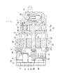
図1に示すように、本実施例の電動コンプレッサ1は、略円筒状のハウジング2と、冷媒を圧縮する圧縮機構3と、駆動力を生じるモータ部4と、モータ部4を制御するインバータ部5と、を備えている。
[Example 1]
As shown in FIG. 1, the electric compressor 1 according to the present embodiment includes a substantially
略円筒状のハウジング2は、圧縮機構3とモータ部4とを内部に収容するリアケース7と、リアケース7の開口端を覆うように配置されるフロントケース9と、リアケース7と他側のフロントケース9に連結されるインバータケース11と、から構成されている。
The substantially
有底筒状に形成されたリアケース7内に収容される圧縮機構3は、内周に楕円形状を有するシリンダブロック13と、シリンダブロック13の両端部を狭持するように配置されるサイドブロック15と、シリンダブロック13の内周に回転自在に収容されるロータ17と、ロータ17に形成されるベーン溝に収容されるベーン19と、ロータ17と一体に形成されて後述するモータ部4から駆動力が伝達されて回転する駆動軸21と、から構成されている。
The
なお、圧縮機構3がリアケース7に圧入して固定されることで、リアケース7の底面側に冷媒を吐出する吐出室43が形成される。この吐出室43には、気体状の冷媒と、吐出された冷媒に含まれる液体であるオイル等とを分離する気液分離器47が配置されている。
The
また、リアサイドブロック15aとフロントサイドブロック15bとによってシリンダブロック13の両端部を狭持することにより、シリンダブロック13の内周にシリンダ室35が形成される。ロータ17が回転することにより、ロータ17に形成されたベーン溝からベーン19が飛び出し、ベーン19の先端がシリンダブロック13の内壁と当接し、さらにロータ17が回転することによって、冷媒を圧縮している。圧縮した冷媒は上述した吐出室43へ吐出される。
Further, by sandwiching both ends of the
ロータ17を回転させる駆動源となるモータ部4は、リアケース7の内周に沿って均等に配置される固定子23と、固定子23の内方側に配置されてロータ17と一体に形成された駆動軸21に圧入して固定されているモータロータ部25と、から構成されている。
The motor unit 4 serving as a driving source for rotating the
固定子23は、図示しないティース部にコイル37を巻回することによって形成されており、このコイル37に電流が流れることにより磁界を発生させ、固定子23の内方に配置されるモータロータ部25を回転させている。
The
また、複数のティースに巻回されたコイル37を引き出して1箇所に集中させて結線するモータ中性点45は、車両搭載時の車両上下方向の上方側に形成されている。このモータ中性点45は、後述するハーメチックターミナル30を介してインバータ部5に接続されている。
Further, a motor
モータ部4を制御するインバータ部5は、フロントケース9のリアケース7と他端側に形成され、インバータケース11によって密閉されて形成されたインバータ室26内に配置されている。
The
インバータ部5は、電子部品27と基板29と、から形成されており、電子部品27は、発熱するスイッチング素子39(インテンリジェントパワーモジュール等)と、スイッチング素子39よりも突出高さの大きい背高部品41(コモンモードコイル、ノーマルモードコイル、インバータ入力用コンデンサ、トランス、内部電源用コンデンサ等)と、によって構成されている。
The
インバータ室26内に配置される電子部品27は、電子部品27の中でも駆動軸21方向に突出高さの低いスイッチング素子39をインバータ室26の車両上下方向の下方側に配置し、スイッチング素子39とよりも駆動軸21方向の突出高さの高い背高部品41をインバータ室26の車両上下方向の上方側に配置している。
The
リアケース7とインバータケース11との間には、フロントケース9が配置されている。リアケース7の開口端を覆うようにフロントケース9が配置されることにより、モータ室8が形成される。モータ室8には、上述した圧縮機構3とモータ部4が収容されており、モータ室8内の潤滑を保つためにオイルが封入されている。また、モータ室8の外周には、図示しない冷媒吸入口が設けられており、モータ室8内に冷媒を注入している。
A front case 9 is disposed between the rear case 7 and the
フロントケース9内には、上述したモータ部4とインバータ部5を電気的に接続するハーメチックターミナル30と、液化した冷媒を貯留する液冷媒収納部31と、が形成されている。ハーメチックターミナル30は、フロントケース9の車両上下方向の上方側に配置され、液冷媒収納部31は、ハーメチックターミナル30よりも下方側に配置される。
In the front case 9, a
この液冷媒収納部31には、フロントケース9の車両上下方向の下方側の壁面から駆動軸21の軸方向にリアケース7側へ向けて液冷媒収納部31に突出する放熱フィン33が形成されている。なお、放熱フィン33の壁面を挟んで対向する位置には、放熱する電子部品27であるインバータ部5のスイッチング素子39が配置されることが好ましい。
The liquid
次に、本実施例の電動コンプレッサ1の動作について説明する。 Next, operation | movement of the electric compressor 1 of a present Example is demonstrated.
まず、インバータ部5によって、モータ部4の駆動制御を行う。この際、インバータ部5からハーメチックターミナル30、モータ中性点45の順に制御信号が流れることにより、固定子23に電流が流れ磁界が生じる。固定子23から磁界が発生することにより、モータロータ部25が回転し、モータロータ部25と固定された駆動軸21が駆動力を伝達する。
First, drive control of the motor unit 4 is performed by the
モータロータ部25から回転駆動力を伝達された駆動軸21は、一体に形成されたロータ17を回転させ、ロータ17内のベーン溝に収容されたベーン19が遠心力等によってベーン溝から飛び出してシリンダブロック13の内壁と摺接し、さらにロータ17が回転することにより、冷媒を圧縮する。圧縮された冷媒は、図示しない吐出孔から吐出室43へ吐出され、気液分離器47を介して図示しない吐出口から冷凍サイクルへ冷媒を吐出する。
The
電動コンプレッサ1では、冬季など外気温が低い場合、長時間電動コンプレッサ1を起動しないと内部に流入されている冷媒が液化してしまう。この液化した冷媒は、重力によって電動コンプレッサ1の車両搭載時上下方向の下方側に流れて溜まってしまうが、液冷媒収納部31が電動コンプレッサ1の車両搭載時上下方向の下方側に設けられているため、液冷媒収納部31に積極的に液冷媒を溜めることができる。
In the electric compressor 1, when the outside air temperature is low, such as in winter, the refrigerant flowing into the inside is liquefied unless the electric compressor 1 is started for a long time. The liquefied refrigerant flows and accumulates downward in the vertical direction when the electric compressor 1 is mounted on the vehicle due to gravity, but the liquid
このように本発明は、ハウジング2内の下部側に液冷媒収納部31を設けたことにより、液冷媒が重力によってハウジング2の下方側に設けられた液冷媒収納部31に溜まるため、液冷媒がモータ中性点45やハーメチックターミナル30が液冷媒に浸かるのを防止することができ、電動コンプレッサ1内の絶縁性を保つことができる。
As described above, according to the present invention, since the liquid
また、液冷媒収納部31をハーメチックターミナル30とモータ中性点45の下方側に設けることにより、より確実にハーメチックターミナル30とモータ中性点45とが液冷媒に浸かるのを防止することができるため、電動コンプレッサ1内の絶縁性を保つことができる。
Further, by providing the liquid
さらに、ハウジング2に収容される突出高さの大きい電子部品27,41をハウジングの上方側に設けることにより、ハウジング2の下方側に液冷媒収納部31を設けるスペースを十分に確保することができる。
Furthermore, by providing the
さらにまた、インバータ部5の下方側に発熱する電子部品27を配置するとともに、電子部品27の対向する位置から液冷媒収納部31に突出する放熱フィン33を設けたことにより、電子部品27,39から発生する熱を放熱フィン33によって放熱することができるので、インバータ部5が過剰に熱を帯びることを防止することができ、延いてはインバータ部5の破損を防止することができる。
Further, the
また、液冷媒が電動コンプレッサ1内に溜まることによって液冷媒が圧縮機構3に入り込み、この状態で電動コンプレッサ1を起動することで液冷媒を圧縮してしまい、圧縮効率が低下するという問題が生じるが、液冷媒収納部31を設けたことにより、液冷媒が液冷媒収納部31に溜まるので、液冷媒が圧縮機構3に流入するのを防ぐことができる。
Further, the liquid refrigerant accumulates in the electric compressor 1, and the liquid refrigerant enters the
さらに、電動コンプレッサ1内に溜まった液冷媒が、駆動軸等の潤滑性を保つために電動コンプレッサ1内に封入されているオイルを流してしまい、電動コンプレッサ1の破損を招く虞があったが、液冷媒収納部31を設けたことにより、液冷媒がオイルを流すことがない。
Furthermore, the liquid refrigerant accumulated in the electric compressor 1 causes the oil sealed in the electric compressor 1 to flow to maintain the lubricity of the drive shaft and the like, which may cause damage to the electric compressor 1. By providing the liquid
なお、本実施例では、液冷媒収納部31を駆動軸21方向に延設して設けているが、モータ室8の下部側を拡径方向に延設して液冷媒収納部を設けてもよい。すなわち、電動コンプレッサ1内の下部側に液化した液冷媒を貯留するスペースを設ければよい。
In the present embodiment, the liquid
また、本実施例では、インバータ部5とモータ部4との間に液冷媒収納部31を設けているが、インバータ部5とモータ部4のハウジング2外周側に突出するように液冷媒収納部を設けても良い。
Further, in this embodiment, the liquid
〔実施例2〕
図2を用いて本発明の第2の実施例について説明する。なお、上記実施例1と同じ構成は説明を省略する。
[Example 2]
A second embodiment of the present invention will be described with reference to FIG. The description of the same configuration as that of the first embodiment is omitted.
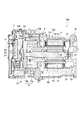
図2に示すように、本実施例の電動コンプレッサ100のハウジング102は、モータ部4を収容するフロントケース107と、圧縮機構3を収容するミドルケース108と、ミドルケース108の開口を塞ぐように配置されるリアケース109と、インバータ部5を収容するインバータケース11と、から構成されている。
As shown in FIG. 2, the
本実施例の電動コンプレッサ100では、フロントケース107の車両搭載時の車両上下方向の下部側には、電動コンプレッサ100内の潤滑を保つオイルが貯留されるオイル貯留部50が形成されている。
In the
また、フロントケース107の底面から駆動軸方向に突出するようにして液冷媒収納部131が形成されている。
Further, a liquid
電動コンプレッサ100の下方側に形成されるオイル貯留部50は、電動コンプレッサ100内に封入されるオイルが貯留するとともに、液化した冷媒が貯留される。すなわち、オイル貯留部50は、液冷媒収納部131としても利用することができる。
The
ミドルケース108に形成された図示しない吸入口から冷媒が吸入され、ミドルケース108に配置された圧縮機構3によって冷媒が圧縮される。圧縮機構3で圧縮された冷媒は、図示しない吐出孔を介してフロントケース107内の吐出され、フロントケース107内に収容されるモータ部4を冷媒によって冷却し、吐出口51から図示しない冷凍サイクルに冷媒を吐出する。
Refrigerant is sucked from a suction port (not shown) formed in the
電動コンプレッサ100が長時間起動しない等によって、ハウジング102内に注入される冷媒が液化した場合、重力によって電動コンプレッサ100の下方側に流れてくる液冷媒が液冷媒収納部131とオイル貯留部50に溜まる。
When the refrigerant injected into the
このような構成とすることにより、上記実施例1と同様の効果を得ることができる。 By adopting such a configuration, the same effect as in the first embodiment can be obtained.
また、オイル貯留部50を液冷媒収納部131として利用することができ、より多くの液冷媒を液冷媒収納部131に溜めることができる。
Further, the
さらに、本実施例のように上記実施例1と異なる形状の電動コンプレッサ100であっても、本発明を適用することができる。
Furthermore, the present invention can be applied to the
本発明は、電動コンプレッサに利用することができる。 The present invention can be used for an electric compressor.
1,100 電動コンプレッサ
2 ハウジング
3 圧縮機構
4 モータ部
5 インバータ部
31,131 液冷媒収納部
DESCRIPTION OF SYMBOLS 1,100
Claims (3)
前記ハウジング(2)の車両上下方向の下方側に液冷媒収納部(31,131)を設け、
前記液冷媒収納部(31,131)は、前記圧縮機構(3)の駆動軸(21)方向に延設され、
前記モータ室(8)の前記インバータ室(26)側端壁の下側が、上側より前記駆動軸方向の前記インバータ室(26)側に延設され、
前記液冷媒収納部(31,131)をハーメチックターミナル(30)とモータ中性点(45)の下方側に設けたことを特徴とする電動コンプレッサ(1,100)。 A substantially cylindrical housing (2), a compression mechanism (3) for compressing refrigerant, a motor part (4) for generating a driving force, an inverter part (5) for controlling the motor part (4), and the motor An electric compressor (1,100) comprising: a motor chamber (8) for accommodating the portion (4); and an inverter chamber (26) for accommodating the inverter portion (5),
Liquid refrigerant storage portions (31, 131) are provided below the housing (2) in the vehicle vertical direction,
The liquid refrigerant storage part (31, 131) extends in the direction of the drive shaft (21) of the compression mechanism (3),
The lower side of the end wall on the inverter chamber (26) side of the motor chamber (8) extends from the upper side to the inverter chamber (26) side in the drive shaft direction,
The electric compressor (1, 100) characterized in that the liquid refrigerant storage portion (31, 131) is provided below the hermetic terminal (30) and the motor neutral point (45 ).
前記ハウジング(2)の車両上下方向の下方側に液冷媒収納部(31,131)を設け、 Liquid refrigerant storage portions (31, 131) are provided below the housing (2) in the vehicle vertical direction,
前記液冷媒収納部(31,131)は、前記圧縮機構(3)の駆動軸(21)方向に延設され、 The liquid refrigerant storage part (31, 131) extends in the direction of the drive shaft (21) of the compression mechanism (3),
前記モータ室(8)の前記インバータ室(26)側端壁の下側が、上側より前記駆動軸方向の前記インバータ室(26)側に延設され、 The lower side of the end wall on the inverter chamber (26) side of the motor chamber (8) extends from the upper side to the inverter chamber (26) side in the drive shaft direction,
前記インバータ部(5)の下方側に発熱する電子部品(27,39)を配置するとともに、前記電子部品(27,39)の対向する位置から前記液冷媒収納部(31)に突出する放熱フィン(33)を設けたことを特徴とする電動コンプレッサ(1,100)。The electronic parts (27, 39) that generate heat are arranged below the inverter part (5), and the radiating fins project into the liquid refrigerant storage part (31) from the position where the electronic parts (27, 39) face each other. (33) The electric compressor (1,100) characterized by the above-mentioned.
前記ハウジング(2)に収容される電子部品(27)において突出高さの大きい電子部品(27,41)をハウジング(2)の上方側に設けることを特徴とする電動コンプレッサ(1,100)。 The electric compressor (1,100) according to claim 1 or 2,
An electric compressor (1, 100) characterized in that an electronic component (27, 41) having a large protruding height is provided above the housing (2) in the electronic component (27) accommodated in the housing (2).
Priority Applications (4)
| Application Number | Priority Date | Filing Date | Title |
|---|---|---|---|
| JP2012265034A JP6178564B2 (en) | 2012-12-04 | 2012-12-04 | Electric compressor |
| PCT/JP2013/077982 WO2014087744A1 (en) | 2012-12-04 | 2013-10-15 | Electric compressor |
| US14/648,986 US20160190899A1 (en) | 2012-12-04 | 2013-10-15 | Electric compressor |
| CN201380062828.3A CN104822941B (en) | 2012-12-04 | 2013-10-15 | electric compressor |
Applications Claiming Priority (1)
| Application Number | Priority Date | Filing Date | Title |
|---|---|---|---|
| JP2012265034A JP6178564B2 (en) | 2012-12-04 | 2012-12-04 | Electric compressor |
Publications (2)
| Publication Number | Publication Date |
|---|---|
| JP2014109250A JP2014109250A (en) | 2014-06-12 |
| JP6178564B2 true JP6178564B2 (en) | 2017-08-09 |
Family
ID=50883172
Family Applications (1)
| Application Number | Title | Priority Date | Filing Date |
|---|---|---|---|
| JP2012265034A Expired - Fee Related JP6178564B2 (en) | 2012-12-04 | 2012-12-04 | Electric compressor |
Country Status (4)
| Country | Link |
|---|---|
| US (1) | US20160190899A1 (en) |
| JP (1) | JP6178564B2 (en) |
| CN (1) | CN104822941B (en) |
| WO (1) | WO2014087744A1 (en) |
Families Citing this family (9)
| Publication number | Priority date | Publication date | Assignee | Title |
|---|---|---|---|---|
| JP6514585B2 (en) * | 2015-06-26 | 2019-05-15 | カルソニックカンセイ株式会社 | Electric compressor |
| JP6514584B2 (en) * | 2015-06-26 | 2019-05-15 | カルソニックカンセイ株式会社 | Electric compressor |
| JP2017008908A (en) * | 2015-06-26 | 2017-01-12 | カルソニックカンセイ株式会社 | Gas compressor |
| US11606056B2 (en) * | 2019-02-12 | 2023-03-14 | Aisin Corporation | Inverter unit |
| US11841031B2 (en) | 2020-03-13 | 2023-12-12 | Honeywell International Inc. | Compressor sensor mount |
| US11635091B2 (en) | 2020-03-13 | 2023-04-25 | Honeywell International Inc. | Compressor with integrated accumulator |
| FR3162483A1 (en) * | 2024-05-23 | 2025-11-28 | Valeo Japan Co., Ltd. | Fluid compression device |
| FR3162482A1 (en) * | 2024-05-23 | 2025-11-28 | Valeo Japan Co., Ltd. | Fluid compression device |
| FR3162484A1 (en) * | 2024-05-23 | 2025-11-28 | Valeo Japan Co., Ltd. | Fluid compression device |
Family Cites Families (18)
| Publication number | Priority date | Publication date | Assignee | Title |
|---|---|---|---|---|
| JP2650978B2 (en) * | 1988-08-29 | 1997-09-10 | 松下冷機株式会社 | Horizontal rotary compressor |
| JPH0311187A (en) * | 1989-06-09 | 1991-01-18 | Toshiba Corp | Horizontal compressor |
| JPH0821391A (en) * | 1994-07-08 | 1996-01-23 | Mitsubishi Heavy Ind Ltd | Transverse installaiion type sealed compressor |
| JP3910327B2 (en) * | 1999-12-22 | 2007-04-25 | 松下電器産業株式会社 | Electric compressor and manufacturing method thereof |
| JP2002070743A (en) * | 2000-08-29 | 2002-03-08 | Sanden Corp | Motor-driven compressor for refrigerant compression |
| JP2007120505A (en) * | 2000-09-29 | 2007-05-17 | Sanden Corp | Motor-driven compressor for compressing refrigerant |
| JP2002202058A (en) * | 2000-12-28 | 2002-07-19 | Sanden Corp | Motor-driven compressor |
| JP2004183631A (en) * | 2002-12-06 | 2004-07-02 | Matsushita Electric Ind Co Ltd | Electric compressor |
| JP3744522B2 (en) * | 2004-03-11 | 2006-02-15 | 松下電器産業株式会社 | Electric compressor |
| JP2007198341A (en) * | 2006-01-30 | 2007-08-09 | Sanden Corp | Motor driven compressor and vehicular air conditioning system using the same |
| JP2008202566A (en) * | 2007-02-22 | 2008-09-04 | Sanden Corp | Electric compressor with built-in inverter |
| JP5115306B2 (en) * | 2008-04-25 | 2013-01-09 | 株式会社豊田自動織機 | Electric compressor |
| JP2010285980A (en) * | 2009-05-13 | 2010-12-24 | Sanden Corp | Inverter-integrated electric compressor |
| JP2012047140A (en) * | 2010-08-30 | 2012-03-08 | Panasonic Corp | Electric compressor |
| WO2012035767A1 (en) * | 2010-09-16 | 2012-03-22 | パナソニック株式会社 | Inverter-integrated electric compressor |
| JP5698007B2 (en) * | 2011-01-19 | 2015-04-08 | 株式会社ヴァレオジャパン | Electric compressor |
| FR2975448B1 (en) * | 2011-05-19 | 2017-07-14 | Valeo Thermal Systems Japan Corp | MODULAR ELECTRICAL COMPRESSOR WITH INTEGRATED FIXING DEVICE |
| WO2014068914A1 (en) * | 2012-10-30 | 2014-05-08 | パナソニック株式会社 | Electric compressor |
-
2012
- 2012-12-04 JP JP2012265034A patent/JP6178564B2/en not_active Expired - Fee Related
-
2013
- 2013-10-15 CN CN201380062828.3A patent/CN104822941B/en not_active Expired - Fee Related
- 2013-10-15 WO PCT/JP2013/077982 patent/WO2014087744A1/en not_active Ceased
- 2013-10-15 US US14/648,986 patent/US20160190899A1/en not_active Abandoned
Also Published As
| Publication number | Publication date |
|---|---|
| JP2014109250A (en) | 2014-06-12 |
| CN104822941B (en) | 2017-08-22 |
| WO2014087744A1 (en) | 2014-06-12 |
| CN104822941A (en) | 2015-08-05 |
| US20160190899A1 (en) | 2016-06-30 |
Similar Documents
| Publication | Publication Date | Title |
|---|---|---|
| JP6178564B2 (en) | Electric compressor | |
| EP2133571B1 (en) | Motor-driven compressor | |
| JP5741346B2 (en) | Electric compressor | |
| KR102483243B1 (en) | Motor-driven compressor | |
| JP5517652B2 (en) | Inverter-integrated electric compressor and assembly method thereof | |
| JP3744522B2 (en) | Electric compressor | |
| CN104251212B (en) | Motor-driven compressor | |
| CN101617458B (en) | Motor and compressor | |
| JP5831484B2 (en) | Electric compressor | |
| JP2018517092A (en) | Compressor | |
| JP2002070743A (en) | Motor-driven compressor for refrigerant compression | |
| CN103443463B (en) | Scroll compression device | |
| JP2004138017A (en) | Reciprocating electric compressor | |
| JP2010112338A (en) | Inverter-integrated electric compressor | |
| US20120275939A1 (en) | Electrically Driven Compressor System for Vehicles | |
| WO2012098624A1 (en) | Electric compressor | |
| WO2016121382A1 (en) | Electric compressor and electronic component | |
| KR101573317B1 (en) | Motor-driven compressor | |
| CN104251189B (en) | Motor-driven compressor | |
| US20110200467A1 (en) | Power driven compressor that prevents overheating of control circuit | |
| JP2004353537A (en) | Electric pump | |
| JP4529973B2 (en) | Electric compressor | |
| WO2016208283A1 (en) | Electrically driven compressor | |
| JP2012026310A (en) | Inverter-integrated electric compressor | |
| JP2016223373A (en) | Electric compressor |
Legal Events
| Date | Code | Title | Description |
|---|---|---|---|
| A621 | Written request for application examination |
Free format text: JAPANESE INTERMEDIATE CODE: A621 Effective date: 20150911 |
|
| A131 | Notification of reasons for refusal |
Free format text: JAPANESE INTERMEDIATE CODE: A131 Effective date: 20160809 |
|
| A521 | Request for written amendment filed |
Free format text: JAPANESE INTERMEDIATE CODE: A523 Effective date: 20160909 |
|
| A131 | Notification of reasons for refusal |
Free format text: JAPANESE INTERMEDIATE CODE: A131 Effective date: 20170110 |
|
| A521 | Request for written amendment filed |
Free format text: JAPANESE INTERMEDIATE CODE: A523 Effective date: 20170214 |
|
| TRDD | Decision of grant or rejection written | ||
| A01 | Written decision to grant a patent or to grant a registration (utility model) |
Free format text: JAPANESE INTERMEDIATE CODE: A01 Effective date: 20170711 |
|
| A61 | First payment of annual fees (during grant procedure) |
Free format text: JAPANESE INTERMEDIATE CODE: A61 Effective date: 20170714 |
|
| R150 | Certificate of patent or registration of utility model |
Ref document number: 6178564 Country of ref document: JP Free format text: JAPANESE INTERMEDIATE CODE: R150 |
|
| LAPS | Cancellation because of no payment of annual fees |