JP6176902B2 - Light emitting diode lamp and lighting fixture - Google Patents
Light emitting diode lamp and lighting fixture Download PDFInfo
- Publication number
- JP6176902B2 JP6176902B2 JP2012183177A JP2012183177A JP6176902B2 JP 6176902 B2 JP6176902 B2 JP 6176902B2 JP 2012183177 A JP2012183177 A JP 2012183177A JP 2012183177 A JP2012183177 A JP 2012183177A JP 6176902 B2 JP6176902 B2 JP 6176902B2
- Authority
- JP
- Japan
- Prior art keywords
- emitting diode
- light emitting
- light
- lamp
- silicone
- Prior art date
- Legal status (The legal status is an assumption and is not a legal conclusion. Google has not performed a legal analysis and makes no representation as to the accuracy of the status listed.)
- Expired - Fee Related
Links
Images


Classifications
-
- F—MECHANICAL ENGINEERING; LIGHTING; HEATING; WEAPONS; BLASTING
- F21—LIGHTING
- F21K—NON-ELECTRIC LIGHT SOURCES USING LUMINESCENCE; LIGHT SOURCES USING ELECTROCHEMILUMINESCENCE; LIGHT SOURCES USING CHARGES OF COMBUSTIBLE MATERIAL; LIGHT SOURCES USING SEMICONDUCTOR DEVICES AS LIGHT-GENERATING ELEMENTS; LIGHT SOURCES NOT OTHERWISE PROVIDED FOR
- F21K9/00—Light sources using semiconductor devices as light-generating elements, e.g. using light-emitting diodes [LED] or lasers
- F21K9/20—Light sources comprising attachment means
- F21K9/23—Retrofit light sources for lighting devices with a single fitting for each light source, e.g. for substitution of incandescent lamps with bayonet or threaded fittings
- F21K9/232—Retrofit light sources for lighting devices with a single fitting for each light source, e.g. for substitution of incandescent lamps with bayonet or threaded fittings specially adapted for generating an essentially omnidirectional light distribution, e.g. with a glass bulb
-
- F—MECHANICAL ENGINEERING; LIGHTING; HEATING; WEAPONS; BLASTING
- F21—LIGHTING
- F21K—NON-ELECTRIC LIGHT SOURCES USING LUMINESCENCE; LIGHT SOURCES USING ELECTROCHEMILUMINESCENCE; LIGHT SOURCES USING CHARGES OF COMBUSTIBLE MATERIAL; LIGHT SOURCES USING SEMICONDUCTOR DEVICES AS LIGHT-GENERATING ELEMENTS; LIGHT SOURCES NOT OTHERWISE PROVIDED FOR
- F21K9/00—Light sources using semiconductor devices as light-generating elements, e.g. using light-emitting diodes [LED] or lasers
- F21K9/90—Methods of manufacture
-
- F—MECHANICAL ENGINEERING; LIGHTING; HEATING; WEAPONS; BLASTING
- F21—LIGHTING
- F21Y—INDEXING SCHEME ASSOCIATED WITH SUBCLASSES F21K, F21L, F21S and F21V, RELATING TO THE FORM OR THE KIND OF THE LIGHT SOURCES OR OF THE COLOUR OF THE LIGHT EMITTED
- F21Y2107/00—Light sources with three-dimensionally disposed light-generating elements
- F21Y2107/30—Light sources with three-dimensionally disposed light-generating elements on the outer surface of cylindrical surfaces, e.g. rod-shaped supports having a circular or a polygonal cross section
-
- F—MECHANICAL ENGINEERING; LIGHTING; HEATING; WEAPONS; BLASTING
- F21—LIGHTING
- F21Y—INDEXING SCHEME ASSOCIATED WITH SUBCLASSES F21K, F21L, F21S and F21V, RELATING TO THE FORM OR THE KIND OF THE LIGHT SOURCES OR OF THE COLOUR OF THE LIGHT EMITTED
- F21Y2107/00—Light sources with three-dimensionally disposed light-generating elements
- F21Y2107/40—Light sources with three-dimensionally disposed light-generating elements on the sides of polyhedrons, e.g. cubes or pyramids
-
- F—MECHANICAL ENGINEERING; LIGHTING; HEATING; WEAPONS; BLASTING
- F21—LIGHTING
- F21Y—INDEXING SCHEME ASSOCIATED WITH SUBCLASSES F21K, F21L, F21S and F21V, RELATING TO THE FORM OR THE KIND OF THE LIGHT SOURCES OR OF THE COLOUR OF THE LIGHT EMITTED
- F21Y2115/00—Light-generating elements of semiconductor light sources
- F21Y2115/10—Light-emitting diodes [LED]
Description
この発明は、たとえば、街路灯用LED(発光ダイオード素子)電球に関するものである。特に、この発明は、街路灯や防犯灯に使用されるHIDランプ(High Intensity Discharge lamp)に近い広い配光のLED電球を実現するものである。 The present invention relates to a street light LED (light emitting diode element) bulb, for example. In particular, the present invention realizes an LED light bulb having a wide light distribution close to an HID lamp (High Intensity Discharge lamp) used for a street light or a security light.
(1)従来HIDランプ:
A.発光光束が大きく広く、遠くまで照らすことが出来るため、街路灯や防犯灯など屋外の用途に広く用いられてきた。またベースダウン、ベースアップの器具にも使われてきた。
B.消費電力が高く寿命が短い(約10000時間)。
C.水銀放電で発光するため、発光管内の水銀が蒸発して明るさが安定するまで時間を要する。
(1) Conventional HID lamp:
A. Since the luminous flux is large and wide and can be illuminated far, it has been widely used in outdoor applications such as street lights and security lights. It has also been used for base-down and base-up equipment.
B. High power consumption and short life (about 10,000 hours).
C. Since light is emitted by mercury discharge, it takes time until the mercury in the arc tube evaporates and the brightness is stabilized.
(2)電球形LED:
A.光の指向性が高く、下面方向への直下照度の改善などある一定方向の照射には向いている(特許文献1:特開2009−4130)。
この場合数個の配置で良く、LED自体が発生する発熱量が少なく、HIDランプのような放電ランプに比べ約40000時間という高い寿命が維持できる。
(2) Light bulb shaped LED:
A. The directivity of light is high, and it is suitable for irradiation in a certain direction such as improvement of the illuminance directly below the bottom surface (Patent Document 1: JP 2009-4130 A).
In this case, several arrangements are sufficient, the amount of heat generated by the LED itself is small, and a high life of about 40000 hours can be maintained as compared with a discharge lamp such as an HID lamp.
B.屋外用の従来HIDランプに替わるLEDランプとして以下のようなランプが考案されている。
従来放電ランプと同様にガラスバルブ21に不活性ガスを封入し、封止した後、スクリュー形の口金23を取付けることで、従来放電ランプとの互換性を容易にすると同時にLEDの背後に凹面鏡を設けることでLEDの光の放射角を拡げている(特許文献2:特開昭62−124781)。
B. The following lamps have been devised as LED lamps to replace conventional outdoor HID lamps.
As with the conventional discharge lamp, an inert gas is sealed in the
A.広く普及している街路灯や防犯灯の器具において、点灯装置を交換するだけで、その反射板や受金はそのまま利用して従来HIDランプと同様に屋外を広く、遠くまで照らすには、HIDランプと比べて実用上遜色ない配光及び発光強度が必要。
B.配光に方向性がなく発光ダイオード11の光がほぼ全方向に配光されれば、下面に主に照射される略水平点灯の街路灯だけでなく、ベースダウン、ベースアップの器具にも対応可能である。
C.特許文献2のLEDランプではHIDランプと遜色ない配光及び発光強度を得ることは難しく、LEDの数を大幅に増やし、HIDランプ同様LEDの光を、全方向に向ける必要がある。
D.多数のLEDの集積によりランプ内が高温となり、LEDが早く劣化して特許文献1のようなLEDランプのような寿命を維持することが難しくなる。また、LEDが発生する熱を逃がすために特許文献1のような金属性の放熱体をLED基板の下面に設置した場合、LEDの数が多く、LEDを縦長の円筒状のバルブに沿って配置するため、放熱体が重くなるだけでなく、縦長配置の長さが長くなるほどその放熱効率は悪くなる。
E.多数のLEDを使用しHIDランプ同様LEDの光を全方向に向けるためには、ランプの長さ方向、円周方向にLEDを分散して配置しなければならず、そのような形状のLED基板を製造するためには、材料費も製造コストも高額となる。
A. HID can be used to illuminate the outdoors widely and far away like conventional HID lamps by simply replacing the lighting device in the widely used street and security light fixtures and using the reflectors and receiving metal. Light distribution and emission intensity that are practically comparable to lamps are required.
B. If the light distribution is non-directional and the light from the
C. With the LED lamp of
D. Due to the accumulation of a large number of LEDs, the temperature inside the lamp becomes high, and the LEDs deteriorate quickly, making it difficult to maintain the life of the LED lamp as in
E. In order to use a large number of LEDs and direct the LED light in all directions like HID lamps, the LEDs must be arranged in a distributed manner in the length direction and circumferential direction of the lamp. In order to manufacture, the material cost and the manufacturing cost become high.
この発明に係る発光ダイオードランプは、
黄色蛍光体を含む色変換用シリコーンと前記色変換用シリコーンで覆われた青色発光半導体素子とを有する発光ダイオードを実装した発光ダイオードユニットと、
前記発光ダイオードユニットの発光面を覆うカバーと、
前記発光ダイオードユニットの発光面と前記カバーの内面との間に充填された透明で絶縁性のある充填シリコーンと
を備え、
前記発光ダイオードは、
前記充填シリコーンが充填されていない場合、10000ケルビン未満の色温度の光を放出し、
前記充填シリコーンが充填されている場合、10000ケルビン以上20000ケルビン以下の色温度の光を放出することを特徴とする。
The light emitting diode lamp according to the present invention is:
A light emitting diode unit mounted with the light emitting diode and a blue light-emitting semiconductor element covered by the color conversion silicone and a color conversion silicone containing yellow phosphor,
A cover covering the light emitting surface of the light emitting diode unit;
And a transparent filled silicone with insulation that is filled between the light emitting surface and the inner surface of the cover of the light emitting diode unit,
The light emitting diode is
Emits light with a color temperature less than 10,000 Kelvin when the filled silicone is not filled;
When the filled silicone is filled, light having a color temperature of 10,000 Kelvin or more and 20000 Kelvin or less is emitted .
この発明によれば、高い色温度の光を発光する発光ダイオードランプを提供することができる。 According to the present invention, a light emitting diode lamp that emits light having a high color temperature can be provided.
実施の形態1.
(1)第1の形態(図1〜図6)
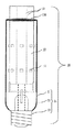
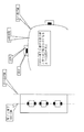
図1に発光ダイオードユニット10の正面側面図、図2に平面図を示す。
発光ダイオードユニット10は、アルミニウム製の八角柱の支持部材13を有する。支持部材13は発光ダイオード11を保持する保持部材である。発光ダイオードユニット10は、支持部材13の頂部に八つの面を持つ台形状の錐体18を有する。
(1) 1st form (FIGS. 1-6)
FIG. 1 is a front side view of the light emitting
The light emitting
錐体18の八つの面に、発光ダイオード11を各1個を搭載したリボン状のフレキシブル基板12(発光ダイオード基板)を耐熱性接着剤で貼り付ける。また、八角柱の八つの側面に発光ダイオード11を各3個を搭載したリボン状のフレキシブル基板12(発光ダイオード基板)を耐熱性接着剤で貼り付ける。
A ribbon-like flexible substrate 12 (light-emitting diode substrate) on which one light-emitting
八角柱の一つの側面とそれに対向する側面との基部(対向する1対の側面の口金23側の基部)に八角柱の軸方向に1対の基部支柱14が取付けられている。
また、八角柱の底面中心にも八角柱の支持部材13の軸方向に軸支柱15が取付けられている。
A pair of
Further, a
八角柱の支持部材13の底面から発光ダイオード11に直流電流を出入力する導入線17が導出されている。
A lead-in
これら3本の支柱は、八角柱の支持部材13の軸方向と垂直方向の別の連結支柱16に連結されている。
これらの各支柱の材質はステンレス製である。
These three support columns are connected to another
These struts are made of stainless steel.
たとえば、八角柱の支持部材13の底面の外接円の直径は50mm、八角柱の支持部材13の角錐部分を含まない部分の高さは150mmである。
発光ダイオード11を搭載する基板は、フレキシブル基板12である。フレキシブル基板12に発光ダイオード11を搭載し、フレキシブル基板12をアルミニウム製の基板に貼り付ける。縦長の基板を連結して角柱形状の多面体構造物を形成する。角柱形状の多面体構造物の頂部を角垂形状にすることで、ガラスバルブ21の半球状またはドーム状の頂部に適合させることができる。角垂形状部分に発光ダイオード11を配置することができる。角垂形状部分の曲げ角度は、ガラスバルブ21の頂部の半径Rに応じて決定する。
For example, the diameter of the circumscribed circle of the bottom surface of the octagonal
A substrate on which the
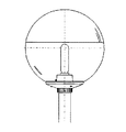
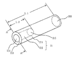
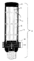
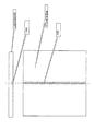
図3に発光ダイオードランプ20の正面側面図、図4に平面図を示す。図5に、口金23なしの正面側面図を示す。
発光ダイオードランプ20は、筺体24を備えている。筺体24は、ガラスバルブ21とフレア管22とを有する。筺体24は、すべて透明である。あるいは、発光ダイオード11が配置されていない筺体24の下部は、不透明でもよい。ガラスバルブ21は、上部が半球状の円筒形の形状をしている。
FIG. 3 is a front side view of the light-emitting
The light emitting
ガラスバルブ21に発光ダイオードユニット10が挿入されている。ガラスバルブ21と発光ダイオードユニット10の空間部には、ガラスバルブ21の半球状の頂部の内面から発光ダイオードユニット10の八角柱の支持部材13の底面の高さまで透明で熱伝導性のシリコーン樹脂(信越シリコーン製シリコーンゴム:KE109)が充填されている(図示せず)。
The light emitting
フレア管22は、ガラスバルブ21端部に融着されたガラス製の封止部である。
八角柱の支持部材13の底面中心から八角柱の支持部材13の軸方向に導出されている軸支柱15は、フレア管22がピンチされるときに、軸支柱15の端部が埋め込まれるように、フレア管22に埋設される。八角柱の支持部材13の底面から導出された導入線17は、ガラスバルブ21端部に融着されたガラス製のフレア管22がピンチされるときに、導入線17の端部がフレア管22の端部から導出されるように、フレア管22に埋設される。
The
The
ガラスバルブ21の端部のチップ管を封止する際に窒素ガスが封入され、バルブ内の空気と置換される。
When sealing the tip tube at the end of the
2本の導入線17はガラスバルブ21端部に設置されるE39口金23に配線される。
The two
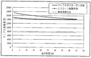
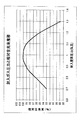
熱伝導性のシリコーン樹脂を充填したものは、充填しないもの(窒素充填のみ)に比べ、図6に示したように、ランプの色温度が高くなり、ランプの色が青色方向にシフトし、より明るく見える。また、ランプの色温度が高くなることから、あらかじめより色温度の低い発光ダイオード11を使うことが出来る。このことは、青色発光ダイオード11に黄色のYAG蛍光体を塗布してなる最も一般的な擬似白色の発光ダイオード11における劣化の原因である黄色のYAG蛍光体の使用量を減らすことが出来る。
As shown in FIG. 6, the one filled with the heat conductive silicone resin has a higher color temperature of the lamp, and the color of the lamp is shifted in the blue direction, as shown in FIG. 6. Looks bright. Further, since the color temperature of the lamp becomes high, the
熱伝導性のシリコーン樹脂の充填によりランプの色が青色方向にシフトする理由については、明確ではないが、シリコーン樹脂のような有機系の物質による赤外から赤色の吸収によるものと考えられる。 The reason why the color of the lamp shifts in the blue direction due to the filling of the thermally conductive silicone resin is not clear, but is considered to be due to absorption from infrared to red by an organic substance such as silicone resin.
なお、口金23はE39口金23を使用したが、HIDランプと互換性のあるE26口金23でも良い。
Although the
実施の形態2.
(2)第2の実施の形態(図なし)
第1の実施の形態での透明で熱伝導性のシリコーン樹脂の代わりに、透明な熱伝導性液体としてパーフルオロカーボン液体が充填されてもよい。パーフルオロカーボン液体は高密度で発光ダイオード11が発生する熱を効率よく吸収しガラスバルブ21に伝達する。パーフルオロカーボン液体は、絶縁性の液体で導入線17等の配線部に接触してもショートの問題はない。
(2) Second embodiment (not shown)
Instead of the transparent and heat conductive silicone resin in the first embodiment, a perfluorocarbon liquid may be filled as a transparent heat conductive liquid. The perfluorocarbon liquid has a high density and efficiently absorbs heat generated by the
パーフルオロカーボン液体を充填したものは、図6に示したように、充填しないもの(窒素充填のみ)に比べ、ランプの色温度が高くなり、ランプの色が青色方向にシフトし、より明るく見える。また、ランプの色温度が高くなることから、あらかじめより色温度の低い発光ダイオード11を使うことが出来る。このことは、青色発光ダイオード11に黄色のYAG蛍光体を塗布してなる最も一般的な擬似白色の発光ダイオード11における劣化の原因である黄色のYAG蛍光体の使用量を減らすことが出来る。
As shown in FIG. 6, the lamp filled with the perfluorocarbon liquid has a higher color temperature of the lamp and the lamp color shifts in the blue direction and appears brighter than the lamp not filled (only with nitrogen). Further, since the color temperature of the lamp becomes high, the
パーフルオロカーボン液体の充填によりランプの色が青色方向にシフトする理由については、明確ではないが、パーフルオロカーボン液体による赤外から赤色の吸収によるものと考えられる。 The reason why the color of the lamp shifts in the blue direction due to the filling of the perfluorocarbon liquid is not clear, but is considered to be due to absorption of infrared to red by the perfluorocarbon liquid.
たとえば、密度1.83(kg/m3@25℃)、比熱1.050(J/kgK@25℃)、絶縁耐力43kV(2.54mmGap@25℃)、誘電率1.91kV(@25℃)〔1kHz〕の住友スリーエム(株)社製「フロリナート(「FLUORINERT」は登録商標)」FC−3283を充填する。 For example, density 1.83 (kg / m 3 @ 25 ° C.), specific heat 1.050 (J / kg K @ 25 ° C.), dielectric strength 43 kV (2.54 mm Gap @ 25 ° C.), dielectric constant 1.91 kV (@ 25 ° C. ) [1 kHz] Sumitomo 3M Co. "Fluorinert (" FLUORINERT "is a registered trademark)" FC-3283 is filled.
なお、パーフルオロカーボン液体は透明で絶縁性があり、水よりも高密度で比熱が水並みであれば、通電状態で直接発光ダイオード基板を冷却することが出来、かつ水冷より放熱効率が良くなるため、密度1.5(kg/m3@25℃)以上であれば良い。 The perfluorocarbon liquid is transparent and insulative, and if the density is higher than water and the specific heat is similar to water, the light emitting diode substrate can be cooled directly in the energized state, and the heat radiation efficiency is better than water cooling. The density may be 1.5 (kg / m 3 @ 25 ° C.) or more.
たとえば、密度1.68(kg/m3@25℃)、比熱1.050(J/kgK@25℃)、絶縁耐力38kV(2.54mmGap@25℃)、誘電率1.76kV(@25℃)〔1kHz〕の住友スリーエム(株)社製「フロリナート(「FLUORINERT」は登録商標)」FC−72でもよい。
For example, density 1.68 (kg / m 3 @ 25 ° C.), specific heat 1.050 (J / kg K @ 25 ° C.),
実施の形態3.
(3)第3の実施の形態(図7〜図13)
以下、実施の形態1,2と異なる点を説明する。
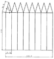
図7に発光ダイオードユニット10の支持部材13の展開図を示す。
図8、図9に発光ダイオードユニット10の正面側面図、平面図を示す。
(3) Third embodiment (FIGS. 7 to 13)
Hereinafter, differences from the first and second embodiments will be described.
FIG. 7 is a development view of the
8 and 9 are a front side view and a plan view of the light emitting
支持部材13は図のように、アルミニウム製の一体型の板を折り曲げて立体化し、複数の面を形成する。一体型の板を折り曲げて形成すれば、熱伝導性が向上する。
As shown in the figure, the
図10に発光ダイオードユニット10の正面側面図、図11に平面図を示す。
FIG. 10 is a front side view of the light emitting
アルミニウム製の八角柱の支持部材13の頂部にアルミニウム製の八角錐を有する。
八角錐の八つの面のうち4つの面発光ダイオード11を各1個を搭載する。また、八角柱の支持部材13の八つの面に発光ダイオード11を1列に各3個搭載する。
上記支持部材13は絶縁処理され、発光ダイオード基板を兼ねる。
An aluminum octagonal pyramid is formed on the top of the aluminum octagonal
Four surface
The
図12に発光ダイオードランプ20の正面側面図、図13に平面図を示す。
FIG. 12 is a front side view of the light-emitting
上部が半球状の円筒形のガラスバルブ21に発光ダイオードユニット10が挿入され、ガラスバルブ21と発光ダイオードユニット10の空間部に充填されている透明な熱伝導性の媒体は実施の形態1及び2と同じである(図示せず)。
The transparent heat conductive medium in which the light emitting
上記ランプの八角柱の支持部材13側面の八角柱の支持部材13の軸と垂直方向の幅w(八角柱の一側面の幅w)は、17.15mm、円筒状のバルブの断面の中心から八角柱の支持部材13側面に垂直に伸ばした線の、八角柱の支持部材13側面と交差する点と、垂直に伸ばした線のバルブ内面と交差する点の距離Δk(前記支持部材13の一側面の中央からバルブ内面との距離Δk)は2.4mm、E39口金23仕様のガラスバルブ21の内径は48mmである。
The width w in the direction perpendicular to the axis of the octagonal
八角形の外接円の直径dは44.8mm、八角柱の支持部材13の高さhは110mmである。
The diameter d of the circumscribed circle of the octagon is 44.8 mm, and the height h of the octagonal
(多角形のnの決定)
多角柱側面の多角柱の軸と垂直方向の幅w:17.15mm、円筒状のバルブの断面の中心から多角柱側面に垂直に伸ばした線の、多角柱側面と交差する点と、垂直に伸ばした線のバルブ内面と交差する点の距離Δkを3.0mm、E39口金23仕様のHIDランプと互換性のあるガラスバルブ21の内径48mmを満足する多角形を選定する。
(Determination of polygon n)
The width of the polygonal column side surface perpendicular to the axis of the polygonal column w: 17.15 mm, perpendicular to the polygonal column side surface from the center of the cross section of the cylindrical bulb, perpendicular to the point intersecting the polygonal column side surface A polygon that satisfies the distance Δk of the point of intersection of the extended line with the inner surface of the bulb at 3.0 mm and the inner diameter of 48 mm that is compatible with the
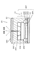
図14の寸法図の記号の意味は、以下のとおりである。
D:ガラスバルブ21の内径
d:発光ダイオードユニット10の外接円の直径
w:発光ダイオードユニット10の一側面の幅
b:ガラスバルブ21の中心から発光ダイオード11までの距離
Δr:ガラスバルブ21の内径Dと外接円の直径dとの差
Δk:発光ダイオード11からガラスバルブ21の内面までの半径方向の距離
Δg:発光ダイオード11から外接円までの半径方向の距離
発光ダイオードユニット10の一側面の幅wは、発光ダイオード11の幅方向の大きさ以上でありかつ信号線が配線できる幅以上である。また、フレキシブル基板を貼り付ける場合は、幅wは、フレキシブル基板の幅以上でありかつ信号線が配線できる幅以上である。
The meanings of the symbols in the dimensional diagram of FIG. 14 are as follows.
D: Inner diameter of glass bulb 21 d: Diameter of circumscribed circle of light emitting diode unit 10 w: Width of one side of light emitting diode unit 10 b: Distance from center of
幅wを大きくすれば、nは小さくなるので、以下のメリットがある。
1.支持部材13の折り曲げ回数は少なくなる。
2.錐体18の頂部の位置合わせが容易になる。
If the width w is increased, n is reduced, and the following advantages are obtained.
1. The number of times of bending of the
2. The alignment of the top of the
幅wを小さくすれば、nは大きくなるので、以下のメリットがある。
1.発光ダイオード11がガラスバルブ21の内面に近づく。
2.放熱効果が高くなる(後述する実施の形態4)
If the width w is decreased, n increases, and the following advantages are obtained.
1. The
2. Increases heat dissipation effect (
多角柱側面の多角柱の軸と垂直方向の幅wのn角形の外接円の直径dは、
Sin(180°/n)=w/d
より、
d=w/Sin(180°/n)
で表される。
The diameter d of the circumscribed circle of the n-gonal shape with the width w in the direction perpendicular to the axis of the polygonal column on the side of the polygonal column is
Sin (180 ° / n) = w / d
Than,
d = w / Sin (180 ° / n)
It is represented by
(d/2)と多角形の中心から多角形の辺に伸ばした垂線の中心と辺と垂線の交点との距離bとの差Δgは、
Δg=d/2−b
b=√((d/2)2−(w/2)2)
より、
Δg=(d/2)−√((d/2)2−(w/2)2)
で表される。
The difference Δg between (d / 2) and the distance b between the center of the perpendicular extending from the center of the polygon to the side of the polygon and the intersection of the side and the perpendicular is
Δg = d / 2−b
b = √ ((d / 2) 2 − (w / 2) 2 )
Than,
Δg = (d / 2) −√ ((d / 2) 2 − (w / 2) 2 )
It is represented by
同心円状に配置されたバルブ内周と多角形の外接円周との距離Δrとすると、
Δr=Δk−Δg
で表される。
When the distance Δr between the inner circumference of the valve arranged concentrically and the circumscribed circumference of the polygon,
Δr = Δk−Δg
It is represented by
このとき決められたwにおいてΔkを満足するバルブ内径Dは、
D=d+2Δr
=d+2(Δk−Δg)
=d+2(Δk−(d/2)+√((d/2)2−(w/2)2))
=d+2Δk−d+2√((d/2)2−(w/2)2)
=2Δk+2√((d/2)2−(w/2)2)
=2Δk+2√((w/2Sin(180°/n))2−(w/2)2)
で表される。
The valve inner diameter D that satisfies Δk at the determined w is
D = d + 2Δr
= D + 2 (Δk−Δg)
= D + 2 (Δk− (d / 2) + √ ((d / 2) 2 − (w / 2) 2 ))
= D + 2Δk−
= 2Δk + 2√ ((d / 2) 2 − (w / 2) 2 )
= 2Δk + 2√ ((w / 2Sin (180 ° / n)) 2 − (w / 2) 2 )
It is represented by
この式は、ガラスバルブ21の内径Dは、Δkとwとnとの関数であることを示している。また、Δkとwとを一定にすると、ガラスバルブ21の内径Dは、nの関数であることを示している。逆に、Δkとwと内径Dを所定の値にするとnが決定されることを示している。
This expression indicates that the inner diameter D of the
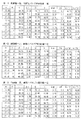
w=17.15mm、Δk=3.0mmとしたとき、図15の表−1よりn=8より求められるD=47.40が目標のD=48mmに最も近い。 When w = 17.15 mm and Δk = 3.0 mm, D = 47.40 obtained from n = 8 from Table-1 in FIG. 15 is closest to the target D = 48 mm.
目標がD=48mm以内である場合には、D=48mm以内になる最大のnを選択すればよい。 When the target is within D = 48 mm, the maximum n that satisfies D = 48 mm may be selected.
以上のように、支持部材13の一側面の幅wを所定の幅w=17.15mmに固定し、前記支持部材13の一側面の中央からバルブ内面との距離Δkを所定の距離Δk=3.0mmに固定し、所定のバルブ径D=48mmを有する円筒状のバルブの内部に前記発光ダイオードユニット10を配置することができる正n角形は、正八角形であることがわかる。すなわち、所定のバルブ径を有する円筒状のバルブの内部に前記発光ダイオードユニット10を配置することができる正n角形のnの最適値は8であることがわかる。
As described above, the width w of one side surface of the
w=17.15mm、Δk=4.0mmとしたとき、図15の表−2よりn=8より求められるD=49.40が目標のD=48mmに最も近い。 When w = 17.15 mm and Δk = 4.0 mm, D = 49.40 obtained from n = 8 from Table-2 in FIG. 15 is closest to the target D = 48 mm.
実際にD=48mmを採用したときのΔkは図16の表−4より3.3mmとなる。
さらに、E26口金23仕様のHIDランプと互換性のあるガラスバルブ21の内径38.6mmを満足する多角形を、図15の表から選定する。
Δk when D = 48 mm is actually adopted is 3.3 mm from Table-4 in FIG.
Further, a polygon satisfying the inner diameter of 38.6 mm of the
図15の表−2、表−3より、n=6より求められるD=37.7及び39.7が目標のD=38.6mmに最も近い(図17)。 From Table-2 and Table-3 in FIG. 15, D = 37.7 and 39.7 obtained from n = 6 are closest to the target D = 38.6 mm (FIG. 17).
実際にD=38.6mmを採用したときのΔkは、図16の表−4より4.5mmとなる。 Δk when D = 38.6 mm is actually adopted is 4.5 mm from Table-4 in FIG.
w=17.15mmの場合は、n=6以上8以下で目標のD=48mmと目標のD=38.6mmを達成できるので好適である。 When w = 17.15 mm, the target D = 48 mm and the target D = 38.6 mm can be achieved when n = 6 or more and 8 or less.
前記発光ダイオードユニット10は、本来、円柱状であることが望ましいが、発光ダイオード11を配置するために平面が必要である。そのために、多角形を形成するのであるが、その多角形も、円柱に近いほうが理想である。しかし、幅wを小さくすれば、nは大きくなるので、円柱に近づくが、折り曲げ回数の増加により製造工程に複雑さが伴う。
The light-emitting
幅wを大きくすると、nが小さくなり、発光ダイオードユニット10は、三角柱、四角柱になり円柱からかけ離れた形状になる。
When the width w is increased, n is decreased, and the light emitting
w=5mm、15mm、20mm、Δk=5.0mmのケースについて、図18の表−5に示す。 The cases where w = 5 mm, 15 mm, 20 mm, and Δk = 5.0 mm are shown in Table-5 in FIG.
w=5mmの場合は、n=18でも、Dが40mm以上にならないので、目標のD=48mmを達成するためには、w=5mmは不向きである。 In the case of w = 5 mm, even if n = 18, D does not exceed 40 mm. Therefore, in order to achieve the target D = 48 mm, w = 5 mm is not suitable.
w=15mmの場合は、n=6以上8以下で、目標のD=48mmと目標のD=38.6mmを達成できるので好適である。 In the case of w = 15 mm, n = 6 or more and 8 or less is preferable because the target D = 48 mm and the target D = 38.6 mm can be achieved.
w=20mmの場合は、n=6でも、Dが40mm以下にならないので、目標のD=38.6mmを達成するためには、w=20mmは不向きである。 In the case of w = 20 mm, even if n = 6, D does not become 40 mm or less. Therefore, in order to achieve the target D = 38.6 mm, w = 20 mm is unsuitable.
図19は、w=17.15mmで、Δk=1.5mmとΔk=2.0mmとしたときの、表である。Δrがマイナス値の場合は、発光ダイオードユニット10がガラスバルブ21に収納できないことを示している。Δrが1mm未満の場合は、発光ダイオードユニット10がガラスバルブ21に理論的には収納はできるが、ガラスバルブ21の寸法ばらつき(プラスマイナス1〜2mm)等により、組み立て時に発光ダイオードユニット10をガラスバルブ21挿入することが難しくなる。
FIG. 19 is a table when w = 17.15 mm and Δk = 1.5 mm and Δk = 2.0 mm. When Δr is a negative value, it indicates that the light emitting
図15、図16、図18、図19に、計算したw/dとw/Dの値を示す。
前述したとおり、Sin(180°/n)=w/dであるから、この式によれば、nを決定すると、wとdの比がわかる。
15, 16, 18, and 19 show the calculated values of w / d and w / D.
As described above, since Sin (180 ° / n) = w / d, according to this equation, when n is determined, the ratio of w and d is known.
n=4のとき、Sin(180°/n)=0.71=w/d
n=5のとき、Sin(180°/n)=0.59=w/d
n=6のとき、Sin(180°/n)=0.50=w/d
n=7のとき、Sin(180°/n)=0.43=w/d
n=8のとき、Sin(180°/n)=0.38=w/d
n=9のとき、Sin(180°/n)=0.34=w/d
n=10のとき、Sin(180°/n)=0.31=w/d
したがって、nを4〜10としたい場合、wはdの0.71〜0.31にすればよい。
nを6〜8としたい場合、wはdの0.5〜0.38にすればよい。
When n = 4, Sin (180 ° / n) = 0.71 = w / d
When n = 5, Sin (180 ° / n) = 0.59 = w / d
When n = 6, Sin (180 ° / n) = 0.50 = w / d
When n = 7, Sin (180 ° / n) = 0.43 = w / d
When n = 8, Sin (180 ° / n) = 0.38 = w / d
When n = 9, Sin (180 ° / n) = 0.34 = w / d
When n = 10, Sin (180 ° / n) = 0.31 = w / d
Therefore, when n is desired to be 4 to 10, w may be 0.71 to 0.31 of d.
When n is to be 6 to 8, w may be 0.5 to 0.38 of d.
実際には、図15、図16、図18、図19に示したとおり、
D=2Δk+2√((w/2Sin(180°/n))2−(w/2)2))
により、nとΔkとが定まれば、wとDとの比が求められる。
Actually, as shown in FIGS. 15, 16, 18, and 19,
D = 2Δk + 2√ ((w / 2Sin (180 ° / n)) 2 − (w / 2) 2 ))
Thus, if n and Δk are determined, the ratio of w and D can be obtained.
図15の表−1によれば、Δk=3.0mmで、nを4〜10としたい場合、wはdの0.74〜0.29にすればよい。nを6〜8としたい場合、wはdの0.48〜0.36にすればよい。 According to Table-1 in FIG. 15, when Δk = 3.0 mm and n is 4 to 10, w may be 0.74 to 0.29 of d. When n is to be 6 to 8, w may be 0.48 to 0.36 of d.
図15の表−2によれば、Δk=4.0mmで、nを4〜10としたい場合、wはdの0.68〜0.28にすればよい。nを6〜8としたい場合、wはdの0.45〜0.35にすればよい。 According to Table-2 in FIG. 15, when Δk = 4.0 mm and n is desired to be 4 to 10, w may be set to 0.68 to 0.28 of d. When n is to be 6 to 8, w may be 0.45 to 0.35 of d.
図15の表−3によれば、Δk=5.0mmで、nを4〜10としたい場合、wはdの0.63〜0.27にすればよい。nを6〜8としたい場合、wはdの0.43〜0.33にすればよい。 According to Table 3 in FIG. 15, when Δk = 5.0 mm and n is desired to be 4 to 10, w may be set to 0.63 to 0.27 of d. If n is desired to be 6 to 8, w may be 0.43 to 0.33 of d.
図16の表−4によれば、
D=48mmのとき、w=17.15mmは、Dの0.36である。
D=38.6mmのとき、w=17.15mmは、Dの0.44である。
According to Table-4 in FIG.
When D = 48 mm, w = 17.15 mm is 0.36 of D.
When D = 38.6 mm, w = 17.15 mm is 0.44 of D.
以上のように、wはDの0.27〜0.74の範囲がよい。好ましくは、wはDの0.33〜0.38の範囲がよい。さらに、Δkが小さいほうがよいことから、wはdの0.48〜0.36の範囲がよい。 As described above, w is preferably in the range of 0.27 to 0.74 of D. Preferably, w is in the range of 0.33 to 0.38 of D. Furthermore, since it is better that Δk is small, w is preferably in the range of 0.48 to 0.36 of d.
図15〜図19から、目標のD=48mmの場合、目標に最も近くなる好適なnは以下のとおりである。
w=17.15mm、Δk=3.0mmのとき、n=8
w=17.15mm、Δk=4.0mmのとき、n=8
w=15.00mm、Δk=5.0mmのとき、n=8
w=20.00mm、Δk=5.0mmのとき、n=6
From FIG. 15 to FIG. 19, when the target D = 48 mm, suitable n closest to the target is as follows.
When w = 17.15 mm and Δk = 3.0 mm, n = 8
When w = 17.15 mm and Δk = 4.0 mm, n = 8
When w = 15.00 mm and Δk = 5.0 mm, n = 8
When w = 20.00 mm and Δk = 5.0 mm, n = 6
目標のD=36.8mmの場合、目標に最も近くなる好適なnは以下のとおりである。
w=17.15mm、Δk=3.0mmのとき、n=6
w=17.15mm、Δk=4.0mmのとき、n=6
w=15.00mm、Δk=5.0mmのとき、n=6
w=5.00mm、Δk=5.0mmのとき、n=17
For a target D = 36.8 mm, the preferred n that is closest to the target is:
When w = 17.15 mm and Δk = 3.0 mm, n = 6
When w = 17.15 mm and Δk = 4.0 mm, n = 6
When w = 15.00 mm and Δk = 5.0 mm, n = 6
When w = 5.00 mm and Δk = 5.0 mm, n = 17
なお、nは、奇数でもよいが、偶数であれば、支柱構造が簡単になり、製造が容易である。 Note that n may be an odd number, but if it is an even number, the support structure is simplified and manufacturing is easy.
このようにして求められた好適なnによる正n角形の発光ダイオードユニット10を用いることにより、ガラスバルブ21の径を変化させても、発光ダイオードユニット10の各側面の幅wを変える必要がなく、発光ダイオードユニット10の部品の共通化が図れる効果がある。
By using the regular n-square light-emitting
また、好適なnによる正n角形の発光ダイオードユニット10を用いることにより、ガラスバルブ21の径Dを変化させても、発光ダイオード11とガラスバルブ21内面の距離Δkを一定又はほぼ一定に保つことができる効果がある。この発光ダイオード11とガラスバルブ21内面の距離Δkを、発光ダイオード11の熱をガラスバルブ21に効率的に逃がすことが出来る距離(後述する実施の形態4で述べる距離)に設定すれば、放熱効果が高いランプを得ることが出来る。ガラスバルブ21の径が異なるランプを製造した場合でも、放熱効果が同じあるいはほぼ同じランプを実現できる。
Further, by using a regular n-gonal light emitting
実施の形態4.
(4)第4の実施の形態(図20〜図29)
好適な発光ダイオードユニット10の高さと径の寸法比および発光ダイオード11とガラスバルブ21内径部の距離について述べる。
(4) Fourth embodiment (FIGS. 20 to 29)
A preferred dimension ratio between the height and the diameter of the light emitting
(試験方法)
(図20〜図23)
・実施の形態3と同様に発光ダイオード基板を兼ねるアルミニウム製の支持体により異なる八角柱の支持部材13の外接円径Dと八角柱の支持部材13の高さhの発光ダイオードユニット10を作成した(図22、図21)。
・頂部の八角錐は省略した。発光ダイオード11は八角柱の支持部材13の側面の各面に縦1列各3個搭載。
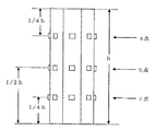
・発光ダイオード11の搭載位置は、
A.各面の高さ方向の中点(b点)、
B.上記Aの位置の発光ダイオード11と側面上端辺の中点(a点)、
C.上記Bの位置の発光ダイオード11と側面下端辺の中点(c点)
のそれぞれ1個合計3個、発光ダイオードユニット10全体では24個搭載した。
・実施の形態1及び実施の形態3と同様のガラスバルブ21の端部を封止し、スクリュー形の口金23を装着する方法でランプを作成した。
・ランプは窒素ガスのみを充填して封止したもの、パーフルオロカーボンで空間部のほぼすべての部分を満たした後、窒素ガスを吹き込みながら封止したものの2種類作成(図22)した。
(Test method)
(FIGS. 20 to 23)
A light emitting
・ The top octagonal pyramid was omitted. Three
-The mounting position of the
A. The midpoint (b point) in the height direction of each surface,
B. The middle point (point a) of the
C. The middle point (point c) of the
A total of 3 each, and 24 light emitting
A lamp was created by sealing the end of the
Two types of lamps were prepared: one that was filled and sealed with only nitrogen gas, and the other that was filled with perfluorocarbon and then sealed while blowing nitrogen gas (FIG. 22).
発光ダイオードユニット10上面とガラスバルブ21頂部内面との距離lはどの条件も20mmとした。
・異なるD:h比の発光ダイオードユニット10はそれぞれが比較できるようにその外接円の径と角柱の高さで構成される体積Vを同一とした。ランプの器具装着性は、器具の形状によっても大きく左右されるが、異なるD:h比の発光ダイオードユニット10のランプの器具装着性について上記Vを同一とすることで簡易的に条件をそろえた。
・発光ダイオード11とガラスバルブ21内径部の距離Δdはガラスバルブ21の径を変えることで変化させた(図23)。
・それぞれのランプを電力、電圧、電流等の条件を同一にして口金23部を下にして点灯した。ガラスバルブ21外面の以下の3点の温度を測定した。
上部の発光ダイオード11の位置(上記B.)に相当する点:a点、
中央部の発光ダイオード11の位置(上記A.)に相当する点:b点、
下部の発光ダイオード11の位置(上記C.)に相当する点:c点
The distance l between the upper surface of the light emitting
The light emitting
The distance Δd between the
-Each lamp was lit with the base, 23 parts down, with the same conditions such as power, voltage, and current. The following three temperatures on the outer surface of the
Points corresponding to the position of the upper light emitting diode 11 (B. above): point a,
Points corresponding to the position of the
Point corresponding to the position of the lower light emitting diode 11 (C. above): point c
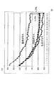
(結果)
(好適なh/D)
・図24の表−6:窒素ガス封入、透明熱伝導媒体なし。
図25に示すように、h/Dが大きいほど温度が下がる。h/D:1.5前後よりh/Dが大きい範囲においてもっとも温度が高いa点においても100℃を下回る。また、温度の下降程度h/D:1.5前後から2.0にかけて、よりなだらかになる。この傾向はより発光ダイオード11に近く、ランプのより上方の部分であるa点でより顕著となる。・図26の表−7:窒素ガス封入、透明熱伝導媒体(パーフルオロカーボン液体)有。
図27に示すように、表−6に比べ全体的に温度が下がる。透明熱伝導媒体(パーフルオロカーボン液体)の効果である。
h/Dが大きいほど温度が下がる。温度の下降程度h/D:1.5前後から2.0にかけて、よりなだらかになる。この傾向はより発光ダイオード11に近く、ランプのより上方の部分であるa点でより顕著となる等の効果は透明熱伝導媒体なしほど顕著ではないが同様の傾向が見られる。
(result)
(Preferred h / D)
Table 6 in FIG. 24: nitrogen gas sealed, no transparent heat conducting medium.
As shown in FIG. 25, the temperature decreases as h / D increases. h / D: Even at point a where the temperature is highest in a range where h / D is larger than about 1.5, the temperature is below 100 ° C. Further, the degree of temperature decrease h / D becomes smoother from about 1.5 to 2.0. This tendency is closer to the
As shown in FIG. 27, the temperature generally decreases as compared to Table-6. This is an effect of a transparent heat conductive medium (perfluorocarbon liquid).
As h / D increases, the temperature decreases. Temperature decrease h / D: From about 1.5 to 2.0, the temperature decreases more gently. This tendency is closer to the
なお、h/Dが大きいほど温度が下がるが、その傾向はh/D:3.0を超えるあたりからほとんど差がなくなる。 In addition, although temperature falls, so that h / D is large, the tendency will almost disappear from the time h / D exceeds about 3.0.
また、h/D:3.5を超えると、ランプを細長としなければならなくなり、従来街路灯に使用されていたHIDランプと寸法が著しく異なるようになり、器具への装着製が損なわれる。 On the other hand, when h / D: 3.5 is exceeded, the lamp must be elongated, and the dimensions are significantly different from those of conventional HID lamps used in street lamps.
h/Dの好適な範囲は1.5から3.5、より好適な範囲は2.0から3.0といえる。 A preferable range of h / D is 1.5 to 3.5, and a more preferable range is 2.0 to 3.0.
(好適なΔdと好適なΔk)
好適な発光ダイオード11とガラスバルブ21の内面との距離について述べる。
・図28の表−8:窒素ガス封入、透明熱伝導媒体(パーフルオロカーボン液体)有。
・発光ダイオード11の表面とガラスバルブ21内面の半径方向の距離Δdはガラスバルブ21の径を変えることで変化させた(図23)。
(Preferred Δd and preferable Δk)
A preferred distance between the
Table 8 in FIG. 28: Nitrogen gas sealed, with transparent heat transfer medium (perfluorocarbon liquid).
The radial distance Δd between the surface of the
図29に示すように、発光ダイオード11がバルブ内面より離れるに従って、温度が上がる。
As shown in FIG. 29, the temperature increases as the
発光ダイオード11がバルブ内面に接触している場合とバルブ内面から20mm離れている場合で20℃から35℃温度が異なる。
The temperature differs from 20 ° C. to 35 ° C. when the
発光ダイオード11がバルブ内面に接触またはバルブ内面に近いほうが、放熱効果が向上し温度的に有利である。
When the
発光ダイオード11とバルブ内面とを離す場合は、バルブを太くするか発光ダイオードユニット10を細くしなければならない。バルブを太くすることは器具装着性に不利、発光ダイオードユニット10を細くすることは配光に不利である。
When separating the
図29に示すように、Δdが、5mm以下の範囲の温度勾配が、5mm以上の範囲の温度勾配よりも、急傾斜であるから、Δdを5mm以下にして、なるべく、0mmにするのがよい。 As shown in FIG. 29, since the temperature gradient in the range where Δd is 5 mm or less is steeper than the temperature gradient in the range where 5 mm or more, Δd should be 5 mm or less and preferably 0 mm. .
したがって、Δdの好適な範囲は、0mm以上5mm以下となる。Δdは、0mmに近いほうが好適である。 Therefore, a preferable range of Δd is 0 mm or more and 5 mm or less. Δd is preferably close to 0 mm.
発光ダイオード11の厚みXは少なくとも1mm以上ある。Δk=Δd+Xであるから、Δkの好適な範囲は1mm以上6mm以下となる。
The
実際には、角柱の支持部材13の各側面間の寸法ばらつき、発光ダイオード11の高さ(厚みX)のばらつき、発光ダイオード11接着時の高さのばらつき及びガラスバルブ21の寸法ばらつき等の設計誤差や製造誤差が存在する。
Actually, design such as dimensional variation between the side surfaces of the
発光ダイオード11がバルブ内面に接触する設計仕様またはバルブ内面に近い設計仕様にすると、前記寸法ばらつき等により各発光ダイオード11間の高さのばらつきが1mm程度あるため、組み立て時に発光ダイオードユニット10をガラスバルブ21に挿入することが難しくなる。組み立て時に発光ダイオードユニット10をガラスバルブ21に挿入するためには円周方向360度全てにおいて最低限のクリアランス(Δr)が必要である。
When the design specification is such that the
発光ダイオード11の高さ(厚みX)が、Δg以下であれば、発光ダイオード11の表面が外接円からはみ出すことがなく円周方向360度全てにおいてクリアランス(Δr)が提供できる。
If the height (thickness X) of the
実施の形態3の図19によれば、Δkが2mm以下の場合、クリアランス(Δr)が1mm未満になり好ましくない。したがって、Δkのより好適な範囲は2mm以上6mm以下となる。放熱効果の点では、Δkは2mmが好適、あるいは、2mmに近いほうが好適である。
According to FIG. 19 of
実施の形態5.
(5)第5の実施の形態(図30〜図34)
図30は、八角柱の支持部材13の発光ダイオードランプ20の図である。
図31は六角柱の支持部材13の発光ダイオードランプ20の図である。
図32〜図34に、発光ダイオードランプ20を搭載した照明器具を示す。配光に方向性がなく発光ダイオード11の光がほぼ全方向に配光されるので、下面に主に照射される略水平点灯の街路灯(図32)だけでなく、ベースダウン、ベースアップの照明器具(図33、図34)にも対応可能である。
(5) Fifth embodiment (FIGS. 30 to 34)
FIG. 30 is a diagram of the light-emitting
FIG. 31 is a diagram of the light-emitting
32 to 34 show a lighting fixture on which the light emitting
上記実施の形態1〜5の発光ダイオードランプ20の構成の特徴を大きく2つの群に分けて以下に特徴と効果とを述べる。
The features of the light-emitting
***第1の特徴群***
特徴1.
角柱状または円筒状の支持部材13に発光ダイオード11を実装した発光ダイオードユニット10を筺体24内に配置し、前記発光ダイオードユニット10より導出された導入線17を前記筺体24の端部に嵌合した口金23に配線した発光ダイオードランプ20において、前記発光ダイオードユニット10の発光面を前記筺体24の一部であるガラス製のカバーで覆うとともに、前記ガラス製のカバー内面と前記発光ダイオードユニット10の角柱状または円筒状の支持部材13の側面に実装された発光ダイオード11が近接または接触しており、前記発光ダイオードユニット10の角柱状または円筒状の支持部材13の軸方向の高さが前記角柱状の支持部材13の底面の外接円または前記円柱状の支持部材13の底面の直径より長いことを特徴とする。
*** First feature group ***
A light emitting
特徴2.
前記発光ダイオードユニット10の角柱状または円筒状の支持部材13の軸方向の高さが前記角柱状の支持部材13の底面の外接円または前記円柱状の支持部材13の底面の直径の1.5倍から3.5倍の長さであることを特徴とする。
The axial height of the prismatic or
特徴3.
前記ガラス製のカバー内面と前記発光ダイオードユニット10の角柱状または円筒状の支持部材13の側面に実装された発光ダイオード11が5mm以内に近接していることを特徴とする。
The
特徴4.
前記発光ダイオードユニット10の発光面とガラス製のカバーの内面の空間には透明で絶縁性を有する熱伝導媒体が充填されていることを特徴とする。
The space between the light emitting surface of the light emitting
特徴5.
前記透明で絶縁性を有する熱伝導性の媒体は、シリコーン樹脂であることを特徴とする。
The transparent and insulating heat conductive medium is a silicone resin.
特徴6.
前記透明な絶縁性を有する熱伝導性の媒体は、密度1.5以上の流体であることを特徴とする。
The transparent heat-conductive medium having an insulating property is a fluid having a density of 1.5 or more.
特徴7.
前記透明な絶縁性を有する熱伝導性の密度1.5以上の流体は、パーフルオロカーボン液体であることを特徴とする。
The transparent, thermally conductive fluid having a density of 1.5 or more is a perfluorocarbon liquid.
特徴8.
前記ガラス製の覆いを含む前記筺体24はすべてガラス製のバルブからなり、前記ガラスバルブ21内には不活性ガスが封入され、前記発光ダイオードユニット10より導出された導入線17をガラスバルブ21外に導出したガラスバルブ21の端部を封止、密閉されていることを特徴とする。
The
特徴9.
前記発光ダイオードユニット10は前記ガラスバルブ21の封止部側に埋設された支柱により保持されていることを特徴とする。
The light emitting
特徴10.
前記発光ダイオード11は基板に実装され、前記基板は前記支持部材13の側面及び上面に設置されていることを特徴とする。
The
特徴11.
前記発光ダイオード11は前記支持部材13の側面及び上面に直接実装されていることを特徴とする。
The
特徴12.
前記ガラスバルブ21の封止端には、スクリュー形の金属口金23が取付けられることを特徴とする。
A screw-
特徴13.
また、照明器具として、前記発光ダイオードランプ20と点灯装置とを配置したことを特徴とする。
Further, the light-emitting
上記発光ダイオードランプ20の各特徴の効果は以下のとおりである。
The effects of the features of the light emitting
特徴1の効果
発光ダイオードユニット10の側面の発光面の発光ダイオード11が、樹脂製のカバーより熱容量が大きいガラス製のカバーに覆われて近接または接しており、角柱状または円筒状の支持部材13の軸方向の高さが角柱状の支持部材13の底面の外接円または円柱状の支持部材13の底面の直径より長い発光ダイオードユニット10とすることで、HIDランプ同様にランプの長さ方向により広い配光と発光強度がえられ、かつ発光ダイオードユニット10の側面より効率良く放熱が可能となることにより、より寿命の長い発光ダイオードランプを提供することが出来る。
Effect of
特徴2の効果
発光ダイオードユニット10の角柱状または円筒状の支持部材13の角柱状または円筒状の部分の軸方向の高さを角柱状の支持部材13の底面の外接円または円柱状の支持部材13の底面の直径の1.5倍から3.5倍の長さにすることにより、HIDランプ同様にランプの長さ方向により広い配光と発光強度がえられ、かつ発光ダイオードユニット10の側面より効率良く放熱が可能となることにより、より寿命の長い発光ダイオードランプを提供することが出来る。
Effect of
特徴3の効果
ガラス製のカバー内面と発光ダイオードユニット10の角柱状または円筒状の支持部材13の側面に実装された発光ダイオード11が10mm以内に近接していることにより、発光ダイオードユニット10の側面より効率良く放熱が可能となり、より寿命の長い発光ダイオードランプ20を提供することが出来る。
Effect of
特徴4の効果
発光ダイオードユニット10の発光面とガラス製のカバーの内面の空間に透明で絶縁性を有する熱伝導媒体を充填することにより、発光ダイオードユニット10の側面より効率良く放熱が可能となり、より寿命の長い発光ダイオードランプ20を提供することが出来る。
Effect of
特徴5の効果
透明で絶縁性を有する熱伝導性の媒体を、シリコーン樹脂とすることにより、より絶縁性が高く、LEDや配線への電気的な安全性を確保することが出来る。また、ランプの色がより高色温度側にシフトすることで、ランプが明るく見える。
Effect of
特徴6の効果
透明な絶縁性を有する熱伝導性の媒体を密度1.5以上の流体とすることにより、熱容量の高い流体の対流によって、ガラスバルブ21または口金23の温度の低い部分に熱を伝達・放出し、より放熱効率が良い発光ダイオードランプ20を提供することが出来る。
Effect of
特徴7の効果
透明な絶縁性を有する熱伝導性の密度1.5以上の流体は、パーフルオロカーボン液体であることによりLEDや配線への電気的な安全性を確保し、より放熱効率が良い発光ダイオードランプ20を提供することが出来る。また、ランプの色がより高色温度側にシフトすることで、ランプが明るく見える。
Effect of
特徴8の効果
ガラス製の覆いを含む筺体24はすべてガラス製のバルブからなり、ガラスバルブ21内には不活性ガスが封入され、
Effect of
発光ダイオードユニット10より導出された導入線17をガラスバルブ21外に導出したガラスバルブ21の端部を封止、密閉するため、ガラスバルブ21の基部に樹脂製のハウジングに接着して筺体24を形成する必要がなく、材料コストが低減できるとともに、既存のHIDランプの設備にて筺体24の生産が可能である。また、不活性ガスが封入され、密閉封止されているので、筺体24内の導入線17等金属部分の腐食が防止できるほか、防水構造となり、屋外においても使用が可能である。更に熱伝導性の液体の媒体を、パッキンなどによる特殊なシーリング構造無しに充填することが出来る。
In order to seal and seal the end of the
特徴9の効果
発光ダイオードユニット10はガラスバルブ21の封止部側に埋設された支柱により保持されていることにより従来HIDランプに近い形状の発光ダイオードランプ20を提供することが出来る。
Effect of
特徴10の効果
発光ダイオード11は基板に実装され、基板は支持部材13の側面及び上面に設置されていることにより、筒状のバルブ形状に近い発光ダイオードユニット10とすることが出来、従来HIDランプに近い配光および形状の発光ダイオードランプ20を提供することが出来る。
Effect of
特徴11の効果
発光ダイオード11は支持部材13の側面及び上面に直接実装されているため発光ダイオード基板を省略することが出来、より安価に発光ダイオードランプ20を生産することが出来る。
Effect of
特徴12の効果
ガラスバルブ21の封止端には、スクリュー形の金属口金23が取付けられることにより、従来HIDランプとほぼ同形状の発光ダイオードランプ20を提供することが出来る。
Effect of Feature 12 A screw-
特徴13の効果
上記発光ダイオードランプ20は、従来HIDランプを使用していた街路灯、防犯灯等の照明器具に、点灯装置との組み合わせにより、容易に置き換えることが出来るため、従来ランプより更に長寿命で、省エネルギー性の高い街路灯、防犯灯などの照明装置を提供することが出来る。
Effect of
***第2の特徴群***
特徴1.
立体化した支持部材13の複数の面に発光ダイオード11を配置することにより構成された発光ダイオードユニット10を、透明な円筒状のバルブと、前記発光ダイオードユニット10に通電する口金23とで形成された筺体24内に設置し、前記発光ダイオードユニット10より導かれた配線を、口金23を介して筺体24外に導出する発光ダイオードランプ20において、前記支持部材13は底面を正多角形とする多角柱形状であり、前記正多角形の底面の外接円が前記円筒状のバルブと同心円状に配置され、前記多角柱側面の前記多角柱の軸と垂直方向の幅wと、前記円筒状のバルブの断面の中心から前記多角柱側面に垂直に伸ばした線の、前記多角柱側面と交差する点と、前記垂直に伸ばした線の前記バルブ内面と交差する点の距離Δkを固定し、前記多角柱の底面の正多角形を正n角形としたとき、所望のバルブ径を得るためにnの数を調節した正多角形からなる多角柱の発光ダイオードユニット10有する。
*** Second feature group ***
A light emitting
特徴2.
立体化した支持部材13の複数の面に発光ダイオード11を配置することにより構成された発光ダイオードユニット10を、透明な円筒状のバルブと、前記発光ダイオードユニット10に通電する口金23とで形成された筺体24内に設置し、前記発光ダイオードユニット10より導かれた配線を、口金23を介して筺体24外に導出する発光ダイオードランプ20において、前記支持部材13は底面を正多角形とする多角柱形状であり、前記正多角形の底面の外接円が前記円筒状のバルブと同心円状に配置され、前記多角柱側面には発光ダイオード11が、前記多角形の軸方向に1列に配置されたことを特徴とする。
A light emitting
特徴3.
前記支持部材13は一体型の板を折り曲げて複数の面を形成して立体化されることを特徴とする。
The
特徴4.
前記多角柱側面の前記多角柱の軸と垂直方向の幅wは5mmから20mmであることを特徴とする。
A width w in a direction perpendicular to the axis of the polygonal column on the side surface of the polygonal column is 5 mm to 20 mm.
特徴5.
前記円筒状のバルブの断面の中心から前記多角柱側面に垂直に伸ばした線の、前記多角柱側面と交差する点と、前記垂直に伸ばした線の前記バルブ内面と交差する点の距離Δkは1mmから6mmであることを特徴とする。
A distance Δk between a point of a line extending perpendicularly to the polygonal column side surface from the center of the cross section of the cylindrical bulb and a point intersecting the polygonal column side surface and a point intersecting the valve inner surface of the vertically extended line is: It is characterized by being 1 mm to 6 mm.
特徴6.
前記立体化した支持部材13の複数の面は発光ダイオード素子基板を兼ね、支持部材13の外面に発光ダイオード11が直接実装されることを特徴とする。
The plurality of surfaces of the three-
特徴7.
発光ダイオードユニット10は、前記支持部材13の複数の面に発光ダイオード素子基板を貼り付けることにより構成された発光ダイオードユニット10であることを特徴とする。
The light emitting
特徴8.
前記発光ダイオード素子基板は、その基板幅が約10mmであることを特徴とする。
The light emitting diode element substrate has a substrate width of about 10 mm.
特徴9.
前記発光ダイオード素子基板は、リボン状のフレキシブル基板12であることを特徴とする。
The light emitting diode element substrate is a ribbon-like
特徴10.
前記多角柱の底面は正n角柱の一部の頂点が欠落した多角形であることを特徴とする。
The bottom surface of the polygonal column is a polygon in which some apexes of the regular n-prism are missing.
特徴11.
前記支持部材13は金属製であることを特徴とする。
The
特徴12.
前記多角柱の高さは前記外接円の直径より高いことを特徴とする。
The height of the polygonal column is higher than the diameter of the circumscribed circle.
特徴13.
前記放熱体の頂面には多角錐形状または断面が台形状の多角錐形状であり前記多角錐形状の各面に発光ダイオード11が配置されていることを特徴とする。
The top surface of the radiator is a polygonal pyramid shape or a trapezoidal polygonal pyramid shape, and a
特徴14.
照明器具において、上記発光ダイオードランプ20と点灯装置とを配置したことを特徴とする。
In the lighting fixture, the light emitting
上記発光ダイオードランプ20の各特徴の効果は以下のとおりである。
The effects of the features of the light emitting
特徴1の効果
立体化した支持部材13の複数の面に発光ダイオード11を配置することにより構成された発光ダイオードユニット10を、透明な円筒状のバルブと、発光ダイオードユニット10に通電する口金23とで形成された筺体24内に設置し、発光ダイオードユニット10より導かれた配線を、口金23を介して筺体24外に導出する発光ダイオードランプ20において、支持部材13は底面を正多角形とする多角柱形状であり、正多角形の底面の外接円が前記円筒状のバルブと同心円状に配置され、多角柱側面の多角柱の軸と垂直方向の幅wと、円筒状のバルブの断面の中心から多角柱側面に垂直に伸ばした線の、多角柱側面と交差する点と、垂直に伸ばした線のバルブ内面と交差する点の距離Δkを固定し、多角柱の底面の正多角形を正n角形としたとき、所望のバルブ径を得るためにnの数を調節した正多角形からなる多角柱の発光ダイオードユニット10有する、発光ダイオードランプ20とすることによって、多角柱側面の幅と側面に配置された発光ダイオード11とガラスバルブ21内面の距離を一定に保ちながら、ガラスバルブ21の径及び発光ダイオードランプ20の明るさを変化させても、部品の共通化及び製造工程の共通化が図れ、かつ発光ダイオード11の熱をガラスバルブ21に効率的に逃がすことが出来、低コストで照明器具互換性が高く、かつ長寿命の発光ダイオードランプ20を得ることが出来る。
Effect of Feature 1 A light-emitting
特徴2の効果
立体化した支持部材13の複数の面に発光ダイオード11を配置することにより構成された発光ダイオードユニット10を、透明な円筒状のバルブと、前記発光ダイオードユニット10に通電する口金23とで形成された筺体24内に設置し、発光ダイオードユニット10より導かれた配線を、口金23を介して筺体24外に導出する発光ダイオードランプ20において、支持部材13は底面を正多角形とする多角柱形状であり、正多角形の底面の外接円が円筒状のバルブと同心円状に配置され、多角柱側面には発光ダイオード11が、多角形の軸方向に1列に配置されたことにより、多角柱の側面の数を容易に調節することができ、所望のバルブ径の発光ダイオードランプ20を得ることによって、多角柱側面の幅と側面に配置された発光ダイオード11とガラスバルブ21内面の距離を一定に保ちながら、ガラスバルブ21の径及び発光ダイオードランプ20の明るさを変化させても、部品の共通化及び製造工程の共通化が図れ、かつ発光ダイオード11の熱をガラスバルブ21に効率的に逃がすことが出来、低コストで照明器具互換性が高く、かつ長寿命の発光ダイオードランプ20を得ることが出来る。
Effect of Feature 2 A light-emitting
特徴3の効果
支持部材13を一体型の板を折り曲げて複数の面を形成することにより、より部品の共通化及び部品点数の減少化及び製造工程の共通化が図れる発光ダイオードランプ20を得ることが出来る。
Effect of
特徴4の効果
多角柱側面の多角柱の軸と垂直方向の幅wを5mmから20mmとすることにより、多角柱側面には発光ダイオード11を多角形の軸方向に1列に配置された状態で、多角柱の側面の数を容易に調節することができ、所望のバルブ径の発光ダイオードランプ20を得ることによって、多角柱側面の幅と側面に配置された発光ダイオード11とガラスバルブ21内面の距離を一定に保ちながら、ガラスバルブ21の径及び発光ダイオードランプ20の明るさを変化させても、部品の共通化及び製造工程の共通化が図れ、かつ発光ダイオード11の熱をガラスバルブ21に効率的に逃がすことが出来、低コストで照明器具互換性が高く、かつ長寿命の発光ダイオードランプ20を得ることが出来る。
Effect of
特徴5の効果
前記円筒状のバルブの断面の中心から前記多角柱側面に垂直に伸ばした線の、前記多角柱側面と交差する点と、前記垂直に伸ばした線の前記バルブ内面と交差する点の距離Δkを1mmから6mmとすることにより、発光ダイオードユニット10をガラスバルブ21に収率良く、容易に挿入することが出来かつ、かつ発光ダイオード11の熱をガラスバルブ21に効率的に逃がすことが出来、低コストで照明器具互換性が高く、かつ長寿命の発光ダイオードランプ20を得ることが出来る。
Effect of Feature 5: A point extending perpendicularly to the polygonal column side surface from the center of the cross section of the cylindrical bulb intersects the polygonal column side surface, and a point intersecting the valve inner surface of the vertically extended line By making the distance Δk of 1 mm to 6 mm, the light emitting
特徴6の効果
立体化した支持部材13の複数の面は発光ダイオード素子基板を兼ね、支持部材13の外面に発光ダイオード11が直接実装されることにより、発光ダイオード基板を省略することが出来、より安価に発光ダイオードランプ20を生産することが出来る。
Effect of Feature 6 A plurality of three-dimensional surfaces of the
特徴7の効果
発光ダイオードユニット10は、支持部材13の複数の面に発光ダイオード素子基板を貼り付けることにより、既存の一般的な発光ダイオード素子基板を流用することが出来る。
Effect of
特徴8の効果
発光ダイオード素子基板を基板幅が約10mmとすることにより、既存に流通しているより一般的な発光ダイオード素子基板を流用することが出来る。
Effect of
特徴9の効果
発光ダイオード素子基板はリボン状のフレキシブル基板12であることにより、既存に流通しているより一般的な発光ダイオード素子基板を流用することが出来る。
Effect of
特徴10の効果
多角柱の底面は正n角柱の一部の頂点を欠落させた多角形であることにより、特殊な器具形状、特殊な配光に合わせた、発光ダイオードユニット10を得ることが出来る。
Effect of
特徴11の効果
支持部材13は金属製であることにより、発光ダイオード11が発生する熱を効率よく吸収、放熱することが出来る。
Effect of
特徴12の効果
多角柱の高さは前記外接円の直径より高いことにより発光ダイオード11が発生する熱を効率よく放熱することが出来る。
Effect of
特徴13の効果
放熱体の頂面には多角錐形状または断面が台形状の多角錐形状であり多角錐形状の各面に発光ダイオード11が配置されていることによりランプ頂部の配光を間然することが出来る。
Effect of
特徴14の効果
上記発光ダイオードランプ20は、従来HIDランプを使用していた街路灯、防犯灯等の照明器具に、点灯装置との組み合わせにより、容易に置き換えることが出来るため、従来ランプより更に長寿命で、省エネルギー性の高い街路灯、防犯灯を提供することが出来る。
Effect of
また、配光に方向性がなく発光ダイオード11の光がほぼ全方向に配光されるので、下面に主に照射される略水平点灯の街路灯だけでなく、ベースダウン、ベースアップの器具にも対応可能である。
In addition, since the light distribution has no directionality and the light from the
実施の形態6.
実施の形態6では、可視域においてほぼ一様な高い透過率を有する液状もしくはペースト状の熱伝導媒体(例えばシリコーン)を、角柱状または円筒状の支持部材にLEDを実装した発光ダイオードユニット10とガラスバルブ21内面との間に充填する方法を説明する。
In the sixth embodiment, a light-emitting
図35は、シリコーン注入方法の比較例1を示す概念図である。
従来のHIDランプにシリコーン290を注入する場合は外管バルブ内に内管バルブを挿入し、外管バルブを封止する。そこで、同様に、ガラスバルブ21に発光ダイオードユニット10を挿入し、ガラスバルブ21内面との隙間に熱伝導媒体を充填し、その後ガラスバルブ21を封止してみた。しかし、封止時の熱により熱伝導媒体が焼損してしまい、採用不可の結果となった。たとえば、シリコーン290は摂氏200度以上になると紛失する可能性があり、封止温度が摂氏1000度以上であるため、シリコーン290が変質してしまう。
FIG. 35 is a conceptual diagram showing Comparative Example 1 of the silicone injection method.
When
図36は、シリコーン注入方法の比較例2を示す概念図である。
HIDランプ製造と同様の製法でガラスバルブ21を封止した後、ガラスバルブ21に開口穴をあけ、そこから熱伝導媒体を注入し、注入後、開口穴を加熱することで封止をする案を考えた。これにより、熱伝導媒体を充填する目的は達成できたが、作業が煩雑でありコストがかかり工業的ではない。
FIG. 36 is a conceptual diagram showing Comparative Example 2 of the silicone injection method.
After sealing the
図37は、実施の形態6のシリコーン注入方法を示す概念図である。
本来、真空引きをする排気管をシリコーン注入に利用することを思いついた。排気管内部に注入針を挿入し、この注入針を通じてガラスバルブ21内部に熱伝導媒体を注入した。これにより効率よく熱伝導媒体を注入することが可能となり、また工業的な手段である。
FIG. 37 is a conceptual diagram showing a silicone injection method according to the sixth embodiment.
Originally, I came up with the idea of using a vacuum exhaust pipe for silicone injection. An injection needle was inserted into the exhaust pipe, and a heat conduction medium was injected into the
図38は、実施の形態6の発光ダイオードランプ20の製造方法、特に、シリコーン注入方法を示すフロー図である。発光ダイオードランプ20の製造工程には、組立工程S20と封止工程S30が有る。
FIG. 38 is a flowchart showing a method for manufacturing the light-emitting
1.組立工程:S20
発光ダイオードランプ20の製造方法は、発光ダイオードユニット10を作成し、発光ダイオードユニット10とフレア管22を装着し、発光ダイオードユニット10をガラスバルブ21に挿入して封止する組立工程S20を備えている。
1. Assembly process: S20
The manufacturing method of the light emitting
図39は、発光ダイオードユニット10の支持部材13の展開図である。
図39が図7と異なる点は、U字状の切り込み218と半円状の切り込み219が存在する点である。切り込み218、219は、支持部材を折り曲げる際に折り曲げやすくする効果と、折り曲げ時の位置きめがしやすくなる効果を有する。切り込み218、219は、U字・半円であるが、三角形、四角形、円形、台形でもよい。
FIG. 39 is a development view of the
39 differs from FIG. 7 in that a
図40は、フレア管22を示す図である。フレア管22はガラスである。フレア管22は2本の導入線17を貫通させている。フレア管22の一端の中央には、軸支柱15が埋めこまれている。フレア管22の他端中央から軸支柱15に向かって排気管221が伸びている。排気管221はフレア管22の中央を貫通しているが、軸支柱15の手前で、斜めに曲がり排気口222を形成している。
FIG. 40 is a diagram showing the
まず、軸支柱15と連結支柱16とを半田付けあるいは溶接により接続して発光ダイオードユニット10とフレア管22とを固定する。さらに、2本の導入線17を発光ダイオードユニット10の回路端子に電気的接続が可能になるように半田付けして接続する。
First, the
次に、発光ダイオードユニット10を試験管状のガラスバルブ21に挿入して、フレア管22の外周とガラスバルブ21の内周とを溶着して、ガラスバルブ21を封止する。
これで、組立工程S20が終了する。
軸支柱15は、発光ダイオードユニット10がガラスバルブに挿入しやすいように軸支柱の軸に対し垂直な方向に柔軟性を持たせるために0.3〜1.5mm程度の細い金属支柱を用いる。最終的には注入されたシリコーンが発光ダイオードユニット10を支えるため、軸支柱はこのように細いものであっても構わない。
Next, the light emitting
This completes the assembly process S20.
As the
図41は、組立工程S20が終了した状態を示す図である。フレア管22とガラスバルブ21とは封止部216で封止され、ガラスバルブ21の内部は、排気口222と排気管221とを介してのみ、外気とつながっている。
FIG. 41 is a diagram illustrating a state in which the assembly process S20 has been completed. The
図41において、換気孔19が発光ダイオードユニット10の内外に貫通孔として存在する。換気孔19は八角柱の端部角に8個設けられている。換気孔19は、切り込み219と底面板金299とが形成した孔である。
In FIG. 41, the
また、図41は、シリコーンディスペンサーのステンレス製の注入針230を示している。注入針230は、ほぼ直線状の針であるが、先端が排気口222から突出できるように曲がっている。注入針230の先端は排気口222の内部を通過できる程度に曲がっている。したがって、注入針230は排気口222内部に挿入できる。
FIG. 41 shows a stainless
2.封止工程:S30
次に、発光ダイオードランプ20の製造方法は、排気管221から熱伝導媒体を充填して排気し封止する封止工程を備えている。封止工程S30は、以下の3工程を順に実行する。
2. Sealing step: S30
Next, the method for manufacturing the light-emitting
(1)充填工程:S31
排気管221にシリコーンディスペンサーの注入針を挿入し、ガラスバルブ21内部にシリコーンディスペンサーから押し出されたシリコーン290を注入する。この時、排気管221の開口部を上向きにしディスペンサーの注入針を挿入する。つまりLEDランプとしては口金が取り付けられるベース側を上向きに配置し、シリコーン290を重力により注入針の先端から垂らして注入する。
シリコーン290の注入と同時に、注入されたシリコーン290の体積分だけ、ガラスバルブ21内の空気は注入針230と排気口222の内面との隙間から流出する。
(1) Filling step: S31
An injection needle of a silicone dispenser is inserted into the
Simultaneously with the injection of the
図42は、シリコーン注入時の図である。シリコーン290は、発光ダイオードの放熱用であるから、発光ダイオードが配置された部分が存在する高さまで充填すればよい。また、発光ダイオードユニット10の内部にまでシリコーン290を注入すると、シリコーン290が大量に使用されてしまうこと、及び、重量が重くなることから、発光ダイオードユニット10の内部には、シリコーン290が入らないように、発光ダイオードユニット10の頂部(図41と図42では下部)を密閉しておくのがよい。シリコーン290が注入される高さまでは発光ダイオードユニット10の内部には、シリコーン290が入らないように発光ダイオードユニット10の隙間をなくしておくのがよい。具体的には、図7の状態から図8の状態に成形した時点で、発光ダイオードユニット10の内側から、接着用シリコーンを塗布して目止めする。接着用シリコーンの色は、支持部材13と同じ色にしておけば、接着用シリコーンが表面にあらわれても表面から目立たない。なお、切り込み218によりできる孔は目止めするが切り込み219によりできる孔は、シリコーン290により覆われないので、また、換気孔19として用いるので目止めしない。
FIG. 42 is a diagram when silicone is injected. Since the
(2)排気工程:S32
注入針を抜き取り、排気管から真空引きを行う(真空引き工程)。これは脱泡のためであるが(真空脱泡)、この時一度に真空引きを行うのではなく、数度に分けて行う。気圧が下がれば、シリコーン内の気体が膨張してシリコーン290の上部に浮いてくることにより、シリコーン290から泡が取り除ける。真空状態から大気圧に戻す際は窒素ガスなどの不活性ガスを注入する(置換工程)。この真空引き工程と置換工程とを数回程度繰り返すことにより、脱泡及び内部の不活性ガス置換が同時に行える。数回の真空引きによりガラスバルブ21内の空気は窒素に徐々に置き換わる。
(2) Exhaust process: S32
The injection needle is pulled out and evacuated from the exhaust pipe (evacuation step). This is for defoaming (vacuum defoaming). At this time, vacuuming is not performed at once, but is performed in several steps. When the atmospheric pressure decreases, the gas in the silicone expands and floats on the top of the
発光ダイオードユニット10の内部に有る空気を窒素ガスに置き換えるため、発光ダイオードユニット10は、発光ダイオードユニット10の底面板金299と切り込み219とにより形成された換気孔19を有している。真空引きにより、発光ダイオードユニット10の内部に有る空気が換気孔19から流出し排気口222から排気される。代わりに、真空状態から大気圧に戻す際は窒素ガスなどの不活性ガスが排気口222から流入し換気孔19から発光ダイオードユニット10の内部に窒素ガスが入る。
In order to replace the air inside the light emitting
(3)チップオフ工程:S33
排気管221のチップオフを行う。
その後、口金が取り付けられる。
(3) Chip-off process: S33
The tip of the
Thereafter, the base is attached.
A.シリコーン290の仕様
シリコーン290の粘度(硬さ)は100Pa・s以下が望ましい。これを越えるとディスペンサーでの吐出が難しくなり、かつ注入したシリコーン290が筐体及びガラスバルブの隙間に均一に入り込まなくなる。特に、50Pa・s以下が望ましいが、より狭い隙間に充填できるようにするためには、1〜数Pa・sがよく、1.0Pa・sが望ましい。
A. Specification of
B.排気管221の仕様
排気管221の太さは最小外径φ4.0mm(最小内径φ0.7mm)、最大外径φ8.0mm(最大内径φ5.0mm)を満たすものがよい。最大外径についてはφ8.0mmを上回るとフレア管22(ステム)として製造が出来なくなり、また最小外径φ4.0mmを下回ると下記に示すようにシリコーン注入と空気を排出する機能が果たせなくなる。
排気管221の長さは最短30mm、最長200mmとするのがよい。排気管221の長さが短くなることはシリコーン注入には有利であるが、最短30mmを下回るとシリコーン注入後のチップオフの作業が出来なくなる。また最長200mmを上回るとシリコーン注入に大幅に不利となる。
B. Specifications of the
The length of the
C.ディスペンサー注入針の仕様
ディスペンサー注入針を使用する理由は2つある。
1つ目はシリコーン注入と空気の排出を同時に行うためである。
2つ目は排気管221内部にシリコーン290を付着しないためである。
万が一、排気管221内部にシリコーン290が付着すると、チップオフの際、溶かしたガラスバルブ内部にシリコーン290が混入し、変色、クラックなどの不具合が生じる危険性がある。
C. Specification of the dispenser injection needle There are two reasons for using the dispenser injection needle.
The first is to perform silicone injection and air discharge simultaneously.
The second reason is that
If the
ディスペンサー注入針の径は使用する排気管221の径による。ディスペンサー注入針の径は太い方がシリコーン注入には有効であるが、チップ間との隙間が狭くなるため空気が排出できなくなる。ディスペンサー注入針の外径の範囲は前記排気管221との関係から最小外径φ0.5mm(最小内径φ0.2mm)mm〜最大外径φ4.5mm(最大内径φ4.0mm)とする。
The diameter of the dispenser injection needle depends on the diameter of the
D.真空引きの仕様
脱泡及び窒素などの不活性ガス置換のための真空引きの条件は真空度は21.33キロパスカル以上101.3キロパスカル未満とする。21.0キロパスカルを下回るとシリコーン290の物性が損なわれる危険性がある。真空度は25キロパスカル以上50キロパスカル以下がよく、具体的には30キロパスカル以上40キロパスカル以下がよく、33.3キロパスカルがなおよい。
また、不活性ガス置換には最低1回以上大気圧に戻す必要がある。脱泡及び不活性ガス置換の完成度と20分程度で10回サイクル程度行うのがよい。
D. Vacuuming specifications The vacuuming conditions for degassing and replacement of inert gas such as nitrogen are such that the degree of vacuum is 21.33 kilopascals or more and less than 101.3 kilopascals. Below 21.0 kilopascals, the physical properties of
Moreover, it is necessary to return to atmospheric pressure at least once for the inert gas replacement. It is preferable to carry out about 10 cycles in about 20 minutes and the degree of completion of defoaming and inert gas replacement.
E.判別方法
なお、排気口222から伝わって垂れた熱伝導媒体の痕跡がフレア管22や基部支柱14や軸支柱15や連結支柱16や導入線17に残るため、熱伝導媒体の痕跡や垂れにより、排気管221からのシリコーン注入方法を採用して製品を製造したことが、目視判別が可能である。
E. Determination method Since the trace of the heat conduction medium that has been dropped from the
実施の形態6の発光ランプの製造方法は、
排気管221を装着してガラスバルブを封止する組立工程と、
排気管221から熱伝導媒体を充填して排気し封止する封止工程と
を備えている。
The manufacturing method of the light-emitting lamp of
An assembly process for mounting the
And a sealing step of filling and exhausting the heat conduction medium from the
封止工程は、
組立工程後、排気管221からガラスバルブ内部に熱伝導媒体を充填する充填工程と、
充填工程後、排気管221からガラスバルブ内部の気体を真空引きする排気工程と、
排気工程後、排気管221を封止するチップオフ工程と
を備えている。
The sealing process
After the assembly process, a filling process for filling the heat conduction medium into the glass bulb from the
After the filling step, an exhaust step of evacuating the gas inside the glass bulb from the
And a chip-off process for sealing the
前記充填工程は、排気管221の管内径より小さな針外径を有する注入針を排気管221に挿入して注入針を介してガラスバルブ内部に熱伝導媒体を注入し、注入針による熱伝導媒体の注入と、排気管221による排気とを同時に行う。
前記充填工程は、排気管221の管長より長い針長を有する注入針を排気管221に挿通して、注入針を介してガラスバルブ内部に熱伝導媒体を注入する。
前記充填工程は、粘度が100パスカル秒以下の熱伝導媒体を注入する。
In the filling step, an injection needle having a needle outer diameter smaller than the inner diameter of the
In the filling step, an injection needle having a needle length longer than the length of the
In the filling step, a heat conduction medium having a viscosity of 100 Pascal seconds or less is injected.
前記封止工程は、管外径が4mm以上8mm以下であり、管内径が管外径より小さくて0.7mm以上5.0mm以下であり、管長が30mm以上200mm以下である排気管221を装着する。
In the sealing step, an
前記充填工程は、針外径が排気管221の管内径より小さく0.5mm以上4.5mm以下であり、針内径が針外径より小さくて0.2mm以上4.0mm以下である注入針を使用してガラスバルブ内部に熱伝導媒体を注入する。
In the filling step, an injection needle whose needle outer diameter is smaller than the inner diameter of the
前記排気工程は、21.0キロパスカル以上101.3キロパスカル以下の真空度で真空引きをする真空引き工程を有する。
前記排気工程は、真空引き工程を複数回繰り返し、真空引き工程の間にガラスバルブ内部の気体を不活性ガスに置換する置換工程を有する。
The evacuation step includes a evacuation step of evacuating at a vacuum degree of 21.0 kilopascals or more and 101.3 kilopascals or less.
The evacuation step includes a replacement step of repeating the evacuation step a plurality of times and replacing the gas inside the glass bulb with an inert gas during the evacuation step.
以上のような製造方法により、発光ダイオードを実装した発光ダイオードユニットと、前記発光ダイオードユニットの発光面を覆うガラス製のカバーを有し、発光ダイオードユニットを内部に配置した筺体と、前記発光ダイオードユニットの発光面とガラス製のカバーの内面の隙間に充填された熱伝導媒体とを備えた発光ダイオードランプが製造できる。 By the manufacturing method as described above, a light emitting diode unit on which a light emitting diode is mounted, a glass cover that covers a light emitting surface of the light emitting diode unit, and a housing in which the light emitting diode unit is disposed, and the light emitting diode unit A light emitting diode lamp provided with a heat conducting medium filled in a gap between the light emitting surface and the inner surface of the glass cover can be manufactured.
前記熱伝導媒体は、透明で絶縁性を有するシリコーン樹脂からなる熱伝導媒体、又は、前記シリコーン樹脂を含む熱伝導媒体である。
シリコーン290を充填すると以下の効果がある。
(1)発光ダイオードの熱がガラスバルブ21に伝わりやすくなる。(2)シリコーン290に覆われた部分は、酸化しない。
(3)仮にガラスバルブ21に外力が加わっても破壊ににくくなる。
(4)ガラスバルブ21が割れても、ガラス片の防飛効果があり、かつ、シリコーン290に覆われている部分には絶縁効果がある。
The heat conducting medium is a heat conducting medium made of a transparent and insulating silicone resin, or a heat conducting medium containing the silicone resin.
Filling
(1) The heat of the light emitting diode is easily transmitted to the
(3) Even if an external force is applied to the
(4) Even if the
注入するシリコーン290は、無色透明がよいが、カラー付シリコーンでもよいし、エポキシ等の他の物質とシリコーン290とのハイブリッドシリコーンでもよい。また、より放熱性をますためには、金属粒子を混ぜた放熱性に富む放熱性シリコーンを使用するのがよい。
The
図41、図42では、排気管221がフレア管22の中で曲がっている場合を示したが、排気管221がフレア管22の中央をまっすぐに突き抜けていてもよい。その場合は、注入針もまっすぐでよく、シリコーン290が排気管221内面に付着する可能性が減少するとともに、シリコーン290の注入が容易になる。
41 and 42 show the case where the
なお、図41、図42では、排気管221のみを介してシリコーン290の注入と排気とを行う場合を示したが、排気管221と平行にシリコーン290を注入する注入管(図示せず)を設けてもよい。注入管を設ける場合は、排気管221にシリコーン290に付着することがなく排気が効率よく確実にできる。注入管を設ける場合は、真空引きの場合に排気管から真空引きをして、注入管から窒素ガスを導入することができる。排気管221と注入管の両方から真空引きし両方から窒素ガスを導入してもよい。最後に排気管221と注入管の両方をチップオフすればよい。
41 and 42 show the case where the
次に、図43と図44を用いて、発光ダイオード11の点灯対策について説明する。
図43は、支持部材とガラスバルブ21の間に発光ダイオード11がシリコーン290で覆われている場合を示している。発光ダイオード11の外殻中央に素子が有り、素子及びボンディングワイヤを樹脂250で覆っている。温度が上昇するとシリコーン290が熱膨張して樹脂250の表面に膨張圧力を加え、樹脂250を押しつぶすように変形させる可能性がある。ガラスバルブ21と支持部材とは、シリコーン290よりも熱膨張係数が小さいため、シリコーン290ほど膨張せず、シリコーン290の行き場がなくなり、比較的柔軟な樹脂250に圧力がかかると考えられる。このため樹脂250内部のボンディングワイヤ251の断線や接触不良を起こし素子の点灯不良が起きる可能性がある。
Next, measures for lighting the
FIG. 43 shows a case where the
そこで、図44に示すように、発光ダイオード11のパッケージ表面に薄板状の透明な板ガラス240を接着して取り付けるのがよい。板ガラス240により膨張圧力が樹脂250に加わるのを緩和することができる。たとえば、樹脂250の厚さは、0.12〜0.17mmであるが、光の透過性が高いほうがよく0.12mmがよい。板ガラス240の形は発光ダイオード11のパッケージ表面の形と同じであればよい。板ガラス240の形は、発光ダイオード11のパッケージの周囲外殻に360度ひっかかる円形や矩形がよい。
Therefore, as shown in FIG. 44, it is preferable to attach a thin plate-like
実施の形態7.
この実施の形態7では、特に、実施の形態1〜6と異なる点について説明する。実施の形態7で特徴となる点は、ガラスバルブ21と発光ダイオードユニット10の形状である。
In the seventh embodiment, differences from the first to sixth embodiments will be particularly described. The feature of the seventh embodiment is the shapes of the
ガラス封入タイプのLEDランプにおいて、放熱性を向上させることは非常に重要である。この実施の形態7では、放熱性能を向上させる場合を説明する。特に、ガラスバルブ21の形状と発光ダイオードユニット10の形状を工夫することにより、放熱性能を向上させる場合を説明する。
In a glass-enclosed LED lamp, it is very important to improve heat dissipation. In this
図45は、実施の形態7におけるガラスバルブ21の斜視図である。
図46は、図45とは逆方向からのガラスバルブ21の斜視図である。
図47は、実施の形態7における図45のガラスバルブ21のAA断面図である。
FIG. 45 is a perspective view of
FIG. 46 is a perspective view of the
FIG. 47 is an AA cross-sectional view of
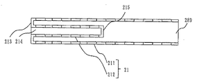
ガラスバルブ21は、外部バルブ211と内部バルブ212とを有している。外部バルブ211の一端には、開放口289が有る。
The
外部バルブ211の内径は内部バルブ212の外径より大きく、外部バルブ211と内部バルブ212の間には、隙間幅Fが360度均等に存在する。
外部バルブ211の内径>内部バルブ212の外径
隙間幅F=((外部バルブ211の内径−内部バルブ212の外径)÷2)
隙間幅F>0
The internal diameter of the
Inner diameter of
Gap width F> 0
外部バルブ211の長さL1は、内部バルブ212の長さL2より大きい。
外部バルブ211の長さL1>内部バルブ212の長さL2
The length L1 of the
Length L1 of
内部バルブ212の内側には、中空部分214が存在している。内部バルブ212の一端の外周は外部バルブ211と連続している。内部バルブ212の一端の中央部分は開放されており、中空部分214に大気が流出入できる。内部バルブ212の他端には底部215が有り、内部バルブ212の底は袋小路になっている。内部バルブ212は、全体として試験管のような形状をしている。
A
内部バルブ212が存在する部分は、ガラスバルブが2重構造になっており、内部バルブ212が存在しない部分は、ガラスバルブが1重構造になっている。
A portion where the
図48は、実施の形態7における発光ダイオードユニット10の正面側面図である。
図49は、実施の形態7における発光ダイオードユニット10の平面図である。
FIG. 48 is a front side view of the light emitting
FIG. 49 is a plan view of the light emitting
実施の形態7における発光ダイオードユニット10の特徴は、発光ダイオードユニット10の支持部材13の頂部の錐体18が存在しない点である。また、発光ダイオードユニット10の支持部材13の底面板金299も存在しない。錐体18も底面板金299も存在しないため、発光ダイオードユニット10は、両端が開放された長さL3の筒状の筒部220を有することになる。発光ダイオードは全て筒部220の表面に配置されている。軸支柱15は連結支柱16にのみ連結されている。
The feature of the light emitting
発光ダイオードユニット10の長さをL4とすると、以下の関係になる。
L1>L4>L3>L2
When the length of the light emitting
L1>L4>L3> L2
図49において、発光ダイオードユニット10の内周円と外周円との半径の差を発光ダイオードユニット10の厚さIとすると、
隙間幅F>厚さI
である。
In FIG. 49, when the difference in radius between the inner and outer circles of the light emitting
Gap width F> Thickness I
It is.
隙間幅Fが最も狭い場合では、
隙間幅F=厚さI
である。放熱性を高めるためには、隙間幅F=厚さIが望ましい。
When the gap width F is the narrowest,
Gap width F = thickness I
It is. In order to improve heat dissipation, it is desirable that the gap width F = thickness I.
図50は、実施の形態7における発光ダイオードランプ20の正面側面図である。
図51は、実施の形態7における発光ダイオードランプ20の平面図である。
図52は、実施の形態7における口金23のない発光ダイオードランプ20の正面側面図である。
図53は、実施の形態7における発光ダイオードランプ20の寸法図である。
FIG. 50 is a front side view of the light-emitting
FIG. 51 is a plan view of the light-emitting
FIG. 52 is a front side view of the light-emitting
FIG. 53 is a dimension diagram of the light-emitting
実施の形態7における発光ダイオードランプ20は、発光ダイオードユニット10とガラスバルブ21を有する。
発光ダイオードユニット10は、発光ダイオード11を配置した筒形状の筒部220を有する。
ガラスバルブ21は、発光ダイオードユニット10の筒部220の内部に設けられた内部バルブ212と、発光ダイオードユニット10の筒部220の外部に設けられた外部バルブ211とを有する。
The light-emitting
The light emitting
The
前記ガラスバルブ21は、筒部220を外部バルブ211と内部バルブ212との間の空間に配置している。
前記ガラスバルブ21は、前記発光ダイオードユニット10を封入している。
前記内部バルブ212は、一端が開放され他端が閉じられ中央に中空部分を有する有底筒形状のガラスバルブである。前記外部バルブ211は、内部バルブ212より長い筒形状のガラスバルブである。
前記ガラスバルブ21は、内部バルブ212の一端と外部バルブ211の一端とを封着した環状端部213と、外部バルブ211の他端を封止した封止部216とを有する。
The
The
The
The
図53は、実施の形態7における発光ダイオードランプ20の寸法図である。図14と異なる点は、外部バルブ211と内部バルブ212に関する以下の寸法が追加された点である。
E:外部バルブ211の外径、
F:隙間幅,
H:外部バルブ211の内面の半径
I:発光ダイオードユニット10の厚さ
FIG. 53 is a dimension diagram of the light-emitting
E: outer diameter of the
F: gap width,
H: Radius of the inner surface of the external bulb 211 I: Thickness of the light emitting
図45〜図53では、断面が8角形の発光ダイオードユニット10を示したが、6角形でもよいし、他の多角形でもよい。あるいは、断面が円形の発光ダイオードユニット10でもよい。
45 to 53 show the light emitting
図示しないが、ガラスバルブ21にシリコーン290を充填してもよい。シリコーン290は、外部バルブ211と内部バルブ212との間全てに充填することが望ましい。発光ダイオードユニット10の表面と裏面との両側にシリコーン290が充填され、発光ダイオードユニット10の表面から外部バルブ211への熱伝導と発光ダイオードユニット10の裏面から内部バルブ212への熱伝導との両方が促進できるからである。
Although not shown, the
また、シリコーン290は、発光ダイオード11の放熱用であるから、発光ダイオード11が配置された筒部220が存在する2重管部分だけに充填すればよい。
図示しないが、発光ダイオードランプ20の前記内部バルブ212の中空部分214に、アルミフィン等の金属放熱部材を備えてもよい。
Further, since the
Although not shown, the
また、図示しないが、前記外部バルブ211の少なくとも内面表面と外面表面とのいずれか又は両方に、放熱部材となる放熱塗料を塗布してもよい。
Moreover, although not shown in figure, you may apply | coat the thermal radiation coating used as a thermal radiation member to at least one of both the inner surface and outer surface of the said
また、同様に、前記内部バルブの少なくとも内面表面と外面表面とのいずれか又は両方に、放熱部材となる放熱塗料を塗布してもよい。
放熱塗料は明るさを維持するためには透明であることが望ましいが、放熱性をますために金属粒子が混入された灰色・薄色の放熱塗料や放熱シリコーンでもかまわない。
Similarly, a heat dissipating paint serving as a heat dissipating member may be applied to at least one of or both the inner surface and the outer surface of the internal valve.
In order to maintain the brightness, it is desirable that the heat dissipating paint be transparent, but in order to increase heat dissipating properties, gray or light color heat dissipating paint or heat dissipating silicone mixed with metal particles may be used.
実施の形態7の発光ダイオードランプは、内部バルブ212の中空部分214からも放熱が促進できる効果がある。放熱性向上により光束劣化が減少し長寿命化が図れる。また、中央先端から凹部が形成されており、今までにない意匠性・デザイン性に富んだ発光ダイオードランプを提供することができる。
The light-emitting diode lamp of the seventh embodiment has an effect that heat dissipation can be promoted also from the
図54は、実施の形態7の発光ダイオードランプの製造方法を示す図である。
実施の形態7の発光ダイオードランプの製造方法は、
二重管部分を有するガラスバルブ21を製造する工程S11と、
発光素子を配置した筒形状の筒部を備えた発光ダイオードユニット10を製造する工程S12と、
前記ガラスバルブ21の二重管部分の間の空間に、発光ダイオードユニット10を配置する組立工程S2と、
前記ガラスバルブ21を封止する封止工程S3と
を備えたことを特徴とする。
FIG. 54 is a diagram showing a method for manufacturing the light-emitting diode lamp of the seventh embodiment.
The manufacturing method of the light-emitting diode lamp of
Step S11 for producing a
Step S12 for manufacturing the light emitting
An assembly step S2 in which the light emitting
And a sealing step S3 for sealing the
前記ガラスバルブ21を製造する工程S11は、一端が開放され他端が閉じられ中央に中空部分を有する有底筒形状の内部バルブ212を、両端が開放され内部バルブ212より長い筒形状の外部バルブ211に挿入し、内部バルブ212の一端と外部バルブ211の一端とを封着する工程を有する。
In the step S11 for manufacturing the
この工程で、図45、図46、図47に示したガラスバルブ21が作成される。
前記発光ダイオードユニット10を製造する工程S12は、実施の形態1〜5で説明した工程を経て発光ダイオードユニット10を製造する。ただし、錐体18は作成しない。底面板金299も使用しない。
In this step, the
In step S12 for manufacturing the light emitting
この工程で、図48に示した発光ダイオードユニット10が作成される。
前記ガラスバルブ21を製造する工程S11と前記発光ダイオードユニット10を製造する工程S12との順番は問わない。
前記組立工程S2は、発光素子を配置した筒形状の筒部を備えた発光ダイオードユニット10にフレア管22を取り付ける。そして、発光ダイオードユニット10を、外部バルブ211の開放口289から挿入して、筒部220を外部バルブ211と内部バルブ212との間の空間に配置する。
In this step, the light emitting
The order of the step S11 for manufacturing the
In the assembling step S2, the
前記封止工程S3は、シリコーン290を注入し、排気管221から排気して排気管221を封止する工程を有する。
前記組立工程S2と前記封止工程S3とは、実施の形態6で述べたガラスバルブ21にシリコーン290を充填する方法を適用することができる。
The sealing step S3 includes a step of injecting
For the assembly step S2 and the sealing step S3, the method of filling the
実施の形態8.
実施の形態8では、実施の形態1〜7で述べた発光ダイオードランプ20を、街路灯に用いる場合について説明する。従来から水銀灯等の高輝度放電ランプ(HIDランプ)を用いた街路灯が存在する。一方、LEDランプを街路灯のランプとして用いられ始めている。
In the eighth embodiment, the case where the light-emitting
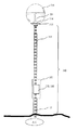
図55は、街路灯の一例を示す図である。
支柱310は、下端が地中に埋設されて地上に立設される。支柱310は、電源を配置する電源配置部311を下部に有し、E形ソケットを配置するソケット配置部312を上部に備え、電源とソケットを結ぶ2本の支柱内電線313を内部に収納している。2本の支柱内電線313の各電線は、断面積が2.0平方mm以上の電線である。2本の支柱内電線313は、1000V以上あるいは1500V以上の交流を通電させても絶縁破壊しない電線である。
FIG. 55 is a diagram illustrating an example of a street lamp.
The
E形ソケット314は、発光ダイオードランプ20のE形口金を取り付けて発光ダイオードランプ20を固定するとともに、発光ダイオードランプ20のE形口金に給電するという2つの機能を有している。
The
電源配置部311には、直流電源315と交流安定器316のいずれかが配置される。
直流電源315と交流安定器316は、地中を引き回され支柱の下端から引き込まれた100V又は200Vの交流商用電源電線317に接続される2個の入力端子を有している。
直流電源315は、定電流直流回路を有し、100V又は200Vの交流商用電源から、20V700mAあるいは40V・350mAあるいは80V・200mA程度の直流定電流を2本の電線に出力する2個の出力端子を有している。
Either the DC power supply 315 or the AC stabilizer 316 is arranged in the power
The DC power supply 315 and the AC stabilizer 316 have two input terminals that are connected to the 100V or 200V AC commercial power supply wire 317 that is drawn through the ground and drawn from the lower end of the column.
The DC power source 315 has a constant current DC circuit, and has two output terminals for outputting a DC constant current of about 20 V 700 mA, 40 V, 350 mA, 80 V, 200 mA to two electric wires from a 100 V or 200 V AC commercial power source. Have.
交流安定器316は、交流昇圧回路を有し、100V又は200Vの交流商用電源から、1000Vあるいは1500Vの交流を2本の電線に出力する2個の出力端子を有している。
発光ダイオードランプ20はランプカバー318により覆われている。
The AC ballast 316 has an AC booster circuit, and has two output terminals for outputting 1000 V or 1500 V AC to two electric wires from a 100 V or 200 V AC commercial power source.
The light emitting
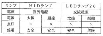
図56は、HIDランプを用いた街路灯とLEDランプを用いた街路灯の仕様比較図である。
街路灯は、支柱とランプとソケットと電源と電線などから構成されているが、故障の原因は、ランプ切れ又は電源回路不良によるものが多い。したがって、街路灯の修理には、交換用ランプや交換用電源を持参して交換する必要がある。
FIG. 56 is a comparison of specifications between a street lamp using an HID lamp and a street lamp using an LED lamp.
A street lamp is composed of a column, a lamp, a socket, a power source, an electric wire, and the like. Therefore, in order to repair the street light, it is necessary to bring a replacement lamp or a replacement power source for replacement.
従来からのHIDランプを用いた街路灯が壊れた場合あるいは寿命が到来した場合、HIDランプをLEDランプに変更するには、実施の形態1〜7で述べた発光ダイオードランプ20に、HIDランプのE形口金と互換性があるE形口金を使用すればよい。また、HIDランプをLEDランプに交換すると同時に、HIDランプ用の交流安定器もLEDランプ用の直流電源に交換すればよい。
In order to change the HID lamp to the LED lamp when the street lamp using the conventional HID lamp is broken or has reached the end of its life, the
今後、街路には、従来からのHIDランプを用いた街路灯と、LEDランプを用いた街路灯とが混在することになる。HIDランプを用いた街路灯とLEDランプを用いた街路灯の仕様は、図56のように異なるため、修理・交換の際には、HIDランプを用いた街路灯と、LEDランプを用いた街路灯とを明確に区別する必要がある。 In the future, street lights using conventional HID lamps and street lights using LED lamps will be mixed in the streets. The specifications of the street lamp using the HID lamp and the street lamp using the LED lamp are different as shown in FIG. 56. Therefore, in the repair / replacement, the street lamp using the HID lamp and the street lamp using the LED lamp are used. It is necessary to clearly distinguish it from street lights.
特に、実施の形態1〜7で述べた発光ダイオードランプ20に、HIDランプのE形口金と互換性があるE形口金を使用すれば、実施の形態1〜7で述べた発光ダイオードランプ20は、HIDランプと物理的に交換可能になるし、交流安定器も直流電源も、2本の入力端子と2本の出力端子を有しているものであるから、支柱の電源配置部に配置できるサイズであれば、交流電源も直流電源も物理的に交換可能となるので、混同する可能性がある。
In particular, if an E-shaped base that is compatible with the E-shaped base of the HID lamp is used for the light-emitting
(1)ランプと電源が正しい組み合わせ
図57は、ランプと電源が正しい組み合わせでも、電線の太さにより不具合が発生する場合を示している。HIDランプは1000V以上(数千V)の交流で動作するため断面積が2平方mm以上の電線を使用しているが、LEDランプは80V以下の直流で動作するため、断面積が0.75平方mmの電線を使用している。したがって、断面積が0.75平方mmの電線に1000V以上の交流が流れた場合は、電線間のショート・断線・破壊などを起こす可能性があり感電の危険がある。特に支柱は金属で製作されていることが多いため、感電・漏電はたいへん危険である。このため、この実施の形態8の街路灯には、断面積が2平方mm以上の太い電線を使用する。太い電線を使用している街路灯であれば、HIDランプでもLEDランプでも安全に点灯させることができる。すなわち、太い電線を使用している街路灯であれば、HIDランプと交流安定器からLEDランプと直流電源に交換してもかまわないし、LEDランプと直流電源からHIDランプと交流電源に交換してもかまわないという安全かつ安心という効果がある。
(1) Correct combination of lamp and power source FIG. 57 shows a case where a failure occurs due to the thickness of the electric wire even if the lamp and power source are correct. HID lamps operate with an alternating current of 1000 V or more (several thousand volts), so electric wires with a cross-sectional area of 2 square mm or more are used. A square mm wire is used. Therefore, when an alternating current of 1000 V or more flows through an electric wire having a cross-sectional area of 0.75 square mm, there is a possibility of short circuit, disconnection, or destruction between the electric wires, which may cause an electric shock. In particular, since the pillars are often made of metal, electric shock and leakage are very dangerous. For this reason, a thick electric wire having a cross-sectional area of 2 square mm or more is used for the street lamp of the eighth embodiment. If it is a street light using a thick electric wire, it can be safely turned on with either an HID lamp or an LED lamp. That is, if the street light uses thick wires, the HID lamp and AC ballast may be replaced with an LED lamp and a DC power source, or the LED lamp and DC power source may be replaced with an HID lamp and an AC power source. It is safe and secure that you don't mind.
(2)ランプと電源の誤った組み合わせ
図58は、ランプと電源が誤った組み合わせで、電線の太さにより不具合が発生する場合を示している。HIDランプと直流電源を組み合わせた場合は、HIDランプが点灯しないだけであり危険はない。
(2) Incorrect combination of lamp and power source FIG. 58 shows a case where a malfunction occurs due to the thickness of the electric wire due to an incorrect combination of the lamp and the power source. When the HID lamp and the DC power supply are combined, the HID lamp is not turned on and there is no danger.
また、LEDランプと交流安定器を組み合わせた場合に太い線を使用していると、LEDランプが点灯しないだけであり危険はない。このLEDランプと交流電源との組み合わせでは、LEDランプに1000V以上の電圧がかかりLEDランプ内の電気回路が破壊されるかもしれないが、実施の形態1〜7で述べた発光ダイオードランプ20の電気回路は、ガラスバルブ21内部に絶縁密閉されているから、感電の危険はなく、最悪でも、LEDランプの回路破損のみで済む。
If a thick wire is used when an LED lamp and an AC ballast are combined, the LED lamp does not light up and there is no danger. In the combination of the LED lamp and the AC power source, a voltage of 1000 V or more may be applied to the LED lamp, and the electric circuit in the LED lamp may be destroyed. However, the electric power of the light-emitting
一方、LEDランプと交流安定器を組み合わせた場合に細い線を使用していると、LEDランプ内の電気回路が短絡した場合は、断面積が0.75平方mmの電線に1000V以上の交流が流れ、電線間のショート・断線・破壊などを起こす可能性があり感電の危険がある。このためにも、この実施の形態8の街路灯には、断面積が2平方mm以上の太い電線を使用する。太い電線を使用している街路灯であれば、たとえランプと電源の組み合わせを間違えた場合でも、感電という危険が生じないという効果がある。 On the other hand, if a thin wire is used when an LED lamp and an AC ballast are combined, when the electrical circuit in the LED lamp is short-circuited, an AC of 1000 V or more is applied to an electric wire having a cross-sectional area of 0.75 square mm. There is a risk of electric shock as it may cause a short circuit, breakage or breakage between the wires. For this purpose, a thick electric wire having a cross-sectional area of 2 square mm or more is used for the street lamp according to the eighth embodiment. A street light that uses a thick electric wire has the effect that there is no danger of an electric shock even if the lamp and power supply are combined incorrectly.
実施の形態8の街路灯は、E形口金を有する発光ダイオードランプ20を使用することを特徴とする。さらに、断面積が2平方mm以上の太い電線を使用することを特徴とする。
The street lamp of the eighth embodiment is characterized by using a light emitting
発光ダイオードランプ20は、発光ダイオードと電気回路とがガラスバルブ21により完全密閉・完全密封された絶縁・防水ランプである。また、シリコーン290が充填されていれば、ガラス破損が防げる堅固なランプであり、仮にガラスが割れてもシリコーン290により覆われた部分の絶縁が保てるランプである。
The light emitting
次に、既設の街路灯のHIDランプを、LEDランプに交換する場合について説明する。
ポール(支柱)を含め街路灯全てをLEDランプの街路灯に換えるためには、既存街路灯の撤去、新規LEDランプ街路灯の購入・設置工事という高額な費用がかかるだけでなく、まだ利用可能なポールの廃却といった環境負荷の問題も発生する。
Next, the case where the existing street lamp HID lamp is replaced with an LED lamp will be described.
In order to replace all street lamps including poles with LED lamp street lights, it is not only expensive to remove existing street lamps, but also to purchase and install new LED lamp street lamps. There is also a problem of environmental burden such as the abolition of a new pole.
すなわち、比較的効率の低い水銀灯などのHIDランプを用いた街路灯照明の光源を高効率な発光ダイオードランプとしつつ、初期設備投資を少なくすべく既設街路灯の支柱(ポール)等の設備を流用し、最低限の加工によりリニューアルを計ることが課題となる。 In other words, while using a highly efficient light-emitting diode lamp as a light source for street lamp illumination using HID lamps such as mercury lamps that are relatively inefficient, divert equipment such as poles for existing street lamps to reduce initial capital investment. However, it is a problem to measure the renewal with the minimum processing.
この実施の形態8における既設の街路灯のHIDランプをLEDランプに交換する場合の、(1)流用する設備と、(2)交換する設備と、(3)その交換方法とは以下のとおりである。
In the case of replacing the HID lamp of the existing street light in this
(1)流用する設備
支柱310、
電源配置部311、
ソケット配置部312、
支柱内電線313、
ランプソケット(E形ソケット)314、
交流商用電源電線317、
ランプカバー318、
(1) Equipment to be used
Power
Lamp socket (E type socket) 314,
AC commercial power cable 317,
(2)交換する設備
HID(水銀、メタルハライド、ナトリウム)ランプ→発光ダイオードランプ20、
交流安定器316→直流電源315、
(2) Equipment to be replaced HID (mercury, metal halide, sodium) lamp → light emitting
AC ballast 316 → DC power supply 315,
(3)ランプ交換方法
実施の形態8で用いるLEDランプは実施の形態1〜7で述べた発光ダイオードランプ20であって、E形口金から給電され、かつ一体の口金を含む光源部内には前記LED用の電源を含んでいない。
(3) Lamp replacement method The LED lamp used in the eighth embodiment is the light-emitting
そして、既存の街路灯のE形ソケットをそのまま使用し、E形ソケットに前記発光ダイオードランプの固定及び給電の両機能を持たせる。
かつ、既存のポールを含む器具を流用し、発光ダイオードランプ電源は既存の交流安定器を撤去したスペースに設置する。
E形ソケットにはLED駆動用の直流電流が供給される。
Then, the E-shaped socket of the existing street lamp is used as it is, and the E-shaped socket is provided with both functions of fixing the light emitting diode lamp and supplying power.
In addition, diverting the equipment including the existing pole, the light-emitting diode lamp power supply is installed in the space where the existing AC ballast is removed.
A direct current for LED driving is supplied to the E-type socket.
前記発光ダイオードランプ用直流電源315はその縦・横・高さとも既存HID用安定器(交流安定器316)の縦・横・高さと同等もしくはそれ以下である。
発光ダイオードランプ用直流電源はその固定用ねじ穴や固定用穴や固定用フック等の取り付け手段が、既存HID用安定器の取り付け手段と同一又は同様な位置にあり、電源配置部からのHID用安定器の撤去後、そのまま発光ダイオードランプ用電源が電源配置部に設置できる。
The direct current power source 315 for the light emitting diode lamp is equal to or less than the length, width, and height of the existing HID ballast (AC ballast 316).
The direct current power supply for the light emitting diode lamp has fixing screw holes, fixing holes, fixing hooks, and the like in the same or similar position as the mounting means of the existing HID ballast. After the ballast is removed, the power source for the light-emitting diode lamp can be installed in the power supply arrangement portion as it is.
前記発光ダイオードランプ20のE形口金及びE形ソケットは、中心部給電端子側がプラスとなる様に、かつ円周側がグランド電位となる様に接続する。
The E-shaped base and E-shaped socket of the light-emitting
こうして、既存のHIDランプの街路灯を発光ダイオードランプの街路灯に、既存設備を流用し最低限の加工により改造できる。 In this way, the existing HID lamp street lamp can be used as a light-emitting diode lamp street lamp, and the existing equipment can be diverted with minimal processing.
以上のように、実施の形態8のランプ交換方法は、E形口金を有する高輝度放電ランプを使用する街路灯のランプを交換する方法である。 As described above, the lamp replacement method according to the eighth embodiment is a method for replacing a street lamp using a high-intensity discharge lamp having an E-shaped base.
実施の形態8のランプ交換方法は、
E形口金を有する高輝度放電ランプをE形口金を有する発光ダイオードランプに交換するランプ交換工程と、
高輝度放電ランプに給電する交流安定器を、発光ダイオードランプに給電する直流電源に交換する電源交換工程と
を備えている。
The lamp replacement method of the eighth embodiment is as follows:
A lamp replacement step of replacing a high-intensity discharge lamp having an E-shaped base with a light-emitting diode lamp having an E-shaped base;
A power supply replacement step of replacing the AC ballast that supplies power to the high-intensity discharge lamp with a DC power source that supplies power to the light-emitting diode lamp.
前記ランプ交換工程は、E形ソケットを交換せず、この交換しないE形ソケットにE形口金を有する発光ダイオードランプを取り付ける。
前記電源交換工程は、電線を交換せず、この交換しない電線に直流電源を接続する。
In the lamp replacement step, the E-shaped socket is not replaced, and a light-emitting diode lamp having an E-shaped base is attached to the E-shaped socket that is not replaced.
In the power supply exchange step, the electric wire is not exchanged, and a DC power supply is connected to the electric wire not to be exchanged.
ポール(支柱)を含め街路灯全てをLEDランプのものに換えるためには、既存街路灯の撤去、新規LEDランプ街路灯の購入・設置工事という高額な費用がかかる、さらに、まだ利用可能なポールの廃却といった環境負荷が発生してしまう。 Replacing all street lamps, including poles, with LED lamps requires expensive costs such as removing existing street lamps and purchasing / installing new LED lamp street lamps. Environmental burdens such as the abolition of waste will occur.
実施の形態8のランプ交換方法によれば、既設の街路灯部品をできる限り流用し、かつエネルギー消費効率のよいLEDランプに転換できる。
屋内体育館のHIDランプ照明においてはその安定器が天井近傍に設置されているのに比べ、通常、屋外街路灯のランプ安定器は支柱下部の交換作業がしやすい位置にあり、カバーを外す事で容易にLED電源の増設もしくは交換工事が可能である。リサイクルの観点からは増設ではなく交換が良い。
According to the lamp replacement method of the eighth embodiment, it is possible to divert existing street light parts as much as possible and convert them to LED lamps with high energy consumption efficiency.
Compared to the HID lamp lighting in indoor gymnasiums, the ballast for outdoor street lamps is usually in a position where it is easy to replace the lower part of the column. LED power supply can be easily expanded or replaced. From the viewpoint of recycling, replacement is good instead of expansion.
ランプに接続するソケットまでの配線は2本存在し従来ここにはHID点灯用の交流電流が流れていたが、既設の2本の電線を用いてLEDランプ点灯用直流電流を流す事が可能で、これも劣化の観点から問題無いものであれば2本の既存配線を流用し、ランプのみを比較的効率の低い水銀灯から前記LEDランプに交換する。 There are two wires to the socket connected to the lamp. Conventionally, AC current for HID lighting has flown here, but it is possible to flow DC current for LED lamp lighting using two existing wires. If there is no problem from the viewpoint of deterioration, two existing wires are used, and only the lamp is replaced with the LED lamp from a mercury lamp with relatively low efficiency.
ここで交換すべきHIDランプが水銀灯等の比較的効率の低いもので有れば改善交換の効果が向上する。比較的効率のよいナトリウムランプやメタルハライドランプからの交換でも改善効果がある。 If the HID lamp to be replaced here is a lamp having a relatively low efficiency such as a mercury lamp, the effect of the improved replacement is improved. Replacing with relatively efficient sodium lamps and metal halide lamps can also be improved.
なお、図32〜図34に示したとおり、発光ダイオードランプ20を搭載した街路灯は略水平点灯(図32)、ベースダウン(図33)、ベースアップ(図34)のいずれでもよい。
As shown in FIGS. 32 to 34, the street light on which the light emitting
また、E形ソケット・E形口金は、E26形でも、E39形のいずれでもよい。また、E形でなくてもよく、ランプ固定と給電との2機能があり、かつ、HIDランプとLEDランプとの物理的取り付け互換性と電気的接触互換性とがあればよい。 The E-type socket / E-type base may be either E26 type or E39 type. Moreover, it does not have to be the E type, it has two functions of lamp fixing and power feeding, and it is sufficient if there is physical mounting compatibility and electrical contact compatibility between the HID lamp and the LED lamp.
実施の形態9.
図59は、放熱性を高めた発光ダイオードランプ20の一例である。
ガラスバルブ21は、発光ダイオードユニット10の支持部材31の一部を覆うとともに、支持部材13の他部を大気中に露出させる。ガラスバルブ21の頭部に開口が有り、開口から発光ダイオードユニット10の支持部材13の他部が露出かつ突出している。発光ダイオード11が存在する部分は、ガラスバルブ21に覆われている。露出かつ突出しているのは、支持部材13のみである。支持部材13は、アルミニウムなどの金属であり、支持部材の端部が大気に直接触れることにより、放熱性が高まる。
FIG. 59 shows an example of the light emitting
The
開口部分には封止部320が有り、封止部320は、防水性を担保するために、ガラスエポキシ系接着剤あるいはシリコーンゴムでコーティング(封止)している。
The opening portion has a sealing
なお、口金部分も、ガラスエポキシ系接着剤あるいはシリコーンゴムでコーティング(封止)してもよい。コーティングにより製造工程が簡略化できかつコストダウンができる。
ガラスバルブ21の内面と外面に放熱塗料を塗布すれば、さらに放熱効果が向上する。
ガラス封入LEDランプでは18wクラスが限度であるが、実施の形態9によれば、放熱性が向上するので大容量化が可能である。
The base portion may also be coated (sealed) with a glass epoxy adhesive or silicone rubber. The coating can simplify the manufacturing process and reduce the cost.
If a heat radiation paint is applied to the inner and outer surfaces of the
In the glass-enclosed LED lamp, the 18w class is the limit, but according to the ninth embodiment, since the heat dissipation is improved, the capacity can be increased.
図60は、放熱性を高めた発光ダイオードランプ20の他の例である。
ガラスバルブ21の口金近くの基部に金属フィン241を装着する。金属フィン241は、環状であり内径がガラスバルブ21の外形と同じであり、スライドしてガラスバルブ21に嵌め込まれる。金属フィン241はアルミニウムなどの金属羽根であり、金属フィン241が大気に直接触れることにより、ガラスバルブ21からの放熱性が高まる。
FIG. 60 shows another example of the light emitting
A
金属フィン241は、位置を確定するために、ガラスバルブ21の突起242まで嵌め込まれている。
金属フィン241は、ガラスエポキシ系接着剤あるいはシリコーン接着剤ではがれないように止める。
金属フィン241の形状、大きさは、ランプカバー318などの邪魔にならないようにする。金属フィン241は、設置空間に応じて、形状、大きさを任意に選択してもよい。その場合は、金属フィン241は、ガラスバルブ21に対して着脱可能にしておく。
The
The
The shape and size of the
ガラスバルブ21の内部全体にシリコーン290を充填すれば、又は、ガラスバルブ21の金属フィン241が存在する部分までシリコーン290を充填すれば、放熱性がさらに高まる。
If the entire inside of the
また、ガラスバルブ21の内面と外面に放熱塗料を塗布すれば、放熱効果が向上する。
ガラス封入LEDランプでは18wクラスが限度であるが、実施の形態9によれば、放熱性が向上するので大容量化が可能である。
Moreover, if a thermal radiation coating is apply | coated to the inner surface and outer surface of the
In the glass-enclosed LED lamp, the 18w class is the limit, but according to the ninth embodiment, since the heat dissipation is improved, the capacity can be increased.
実施の形態10.
以下、前述した実施の形態と異なる点を説明する。
Hereinafter, differences from the above-described embodiment will be described.
大気圧の窒素ガスを封入してチップオフしたガラス封入タイプの発光ダイオードランプを点灯し、摂氏25度から摂氏100度の温度が上昇したと仮定すると、75度の温度上昇による窒素ガスの体積は、約27.5%(75度×1/273)程度膨張する。このため、ガラスバルブ21の内圧は約1.3倍になる。これにより、発光ダイオード11(以下、LEDパッケージともいう)が圧迫され、光束低下につながる恐れがある。
一方、内部を真空にしてチップオフしたガラス封入タイプの発光ダイオードランプを点灯すると、同様に、明るさが低下する恐れがある。
Assuming that a glass-enclosed light emitting diode lamp chipped off with nitrogen gas sealed at atmospheric pressure is turned on and the temperature rises from 25 degrees Celsius to 100 degrees Celsius, the volume of nitrogen gas due to the temperature rise of 75 degrees is About 27.5% (75 degrees × 1/273). For this reason, the internal pressure of the
On the other hand, when a glass-enclosed light-emitting diode lamp that has been chipped off by evacuating the interior is turned on, the brightness may similarly decrease.
以上の結果、以下のことが考えられる。
(1)ガラスバルブの内圧が大気圧より高いと、LEDパッケージ内部が圧迫され、明るさが低下する。
(2)ガラスバルブの内圧が大気圧より低いと、LEDパッケージ内部が減圧し、明るさが低下する。
As a result, the following can be considered.
(1) When the internal pressure of the glass bulb is higher than the atmospheric pressure, the inside of the LED package is pressed and the brightness is lowered.
(2) When the internal pressure of the glass bulb is lower than the atmospheric pressure, the inside of the LED package is depressurized and the brightness is lowered.
したがって、ガラスバルブの内部温度にかかわらず、ガラスバルブの内圧は大気圧であることが望ましい。 Therefore, it is desirable that the internal pressure of the glass bulb is atmospheric pressure regardless of the internal temperature of the glass bulb.
ガラスバルブの内圧を大気圧に保つためには以下の実施例が考えられる。
実施例1.ガラスバルブを封止しない。
実施例2.点灯時にガラスバルブの内圧を大気圧にする。
実施例3.ガラスバルブ内から気体を排除する。
以下、各実施例について説明する。
In order to maintain the internal pressure of the glass bulb at atmospheric pressure, the following examples can be considered.
Example 1. Do not seal the glass bulb.
Example 2 Set the internal pressure of the glass bulb to atmospheric pressure when lit.
Example 3 FIG. Exclude gas from inside the glass bulb.
Each example will be described below.
実施例1.<<<ガラスバルブを封止しない実施例>>>
図61は、排気管221をチップオフではなくチップカットした発光ダイオードユニット10の分解図である。
図62は、フレア管22の概念断面図である。
図63は、チップカットした排気管221に口金23を取り付けた発光ダイオードユニット10の断面図である。
Example 1. <<< Example in which glass bulb is not sealed >>>
FIG. 61 is an exploded view of the light emitting
FIG. 62 is a conceptual cross-sectional view of the
FIG. 63 is a cross-sectional view of the light emitting
前述した実施の形態6で説明したガラス封入タイプの発光ダイオードランプ20では、ガラスバルブ21を封止後、通常のランプ製造工程と同様に、チップオフしているが、この実施例では、光束を維持するため、チップカットする点が特徴である。
In the glass-sealed light-emitting
チップオフとは、ガラスチップ管のようなガラスの細管(排気管221)をガスバーナ等で加熱・溶融させ封止切断することをいう。
チップカットとは、ガラスチップ管のようなガラスの細管(排気管221)を封止せずに切断することをいう。
チップオフすれば、ガラスバルブ21は完全に封止密封され、100%の防水効果がある。
チップカットすれば、ガラスバルブ21は、100%の防水効果はないが、ガラスバルブ21の内部の気圧が大気圧と同じになる効果がある。
Chip-off means heating and melting a thin glass tube (exhaust tube 221) such as a glass chip tube with a gas burner or the like to cut and seal.
Chip cutting means cutting without sealing a thin glass tube (exhaust tube 221) such as a glass chip tube.
If the chip is turned off, the
If the tip is cut, the
図61に示すように、ガラスバルブ21の左端(一方の端部)は閉じた構造となっている。一方、ガラスバルブ21の右端(もう一方の端部)は、フレア管22が溶着されており、ガラスバルブ21の右端周囲にはスクリュー部224が形成されている。
排気管221は、フレア管22を左右に貫通している。排気管221の下端には、排気口222があり、排気管221の右端には、開口部231があり、この開口部231のみで、ガラスバルブ21の内部と外部とが通気できるようになっている。
As shown in FIG. 61, the left end (one end) of the
The
図62に示すように、フレア管22は、内部にくぼんだ凹部223が形成された試験管状あるいはコップ状のガラス胴体228でできている。この凹部223の中央に、排気管221があり、フレア管22の胴部の下部側面の途中に排気口222がある。排気管221の左右には、2本の導入線17があり、フレア管22を上下に貫通している。
As shown in FIG. 62, the
図63に示すように、口金23の内周には外周のネジ山とネジ溝により形成されたネジ溝とネジ山がある。口金23は、ガラスバルブ21の上端周囲にある螺旋状のスクリュー部224にねじ込まれる。そして、口金23は、口金23の外周の一部の半田付け又はかしめにより、逆転不可能にガラスバルブ21の上端に固定される。
As shown in FIG. 63, the inner periphery of the
口金23の内周のネジ山とネジ溝とは、ネジスクリュー部224のネジ溝とネジ山と一致するようになっているが、口金23とガラスバルブ21とはネジ山とネジ溝との間に隙間229ができる。この隙間229を通り、空気がリークする。この隙間229は、ガラスバルブ21の内圧が外気圧を同じになるように気圧を調整するものであり、気圧調整部233の一例である。
The screw thread and the screw groove on the inner periphery of the base 23 coincide with the screw groove and the screw thread of the
***通気経路***
図63の矢印に示すように、空気は以下の経路でリークする。
*** Air ventilation path ***
As shown by the arrows in FIG. 63, air leaks through the following path.
ガラスバルブ21の内部空間←→排気管221の排気口222←→排気管221←→排気管221の開口部231←→口金23の内部空間←→口金23とガラスバルブ21との隙間229(気圧調整部233)←→外気。
The inner space of the
ここで、空気がリークするという意味は、積極的に空気を流通させ放熱させるという意味ではない。ここでの空気がリークするという意味は、ガラスバルブ21の内部空間の温度上昇により膨張した空気がガラスバルブ21の内部で加圧されることにより上記経路をとおり外気中に抜け出ることを意味する。したがって、ガラスバルブ21の内部の圧力は大気圧とほぼ同じになる。
Here, the meaning that air leaks does not mean that air is actively circulated to dissipate heat. The meaning that the air leaks here means that the air expanded by the temperature rise in the internal space of the
以上のように、この実施例は、排気管221をカットして、開口部231を減圧孔として用いている点が特徴である。
As described above, this embodiment is characterized in that the
なお、ガラスバルブ21の内部空間の温度が下降した場合は、ガラスバルブ21の内部空間の温度下降により空気がガラスバルブ21の内部で減圧されることにより外気が上記経路で吸い込まれ、ガラスバルブ21の内部の圧力は大気圧とほぼ同じになる。
When the temperature of the internal space of the
***防水対策***
この実施例では、排気管221を封止していないので、排気管221から水が浸入する恐れがあるので、以下のような防水対策を施すことが望ましい。
*** Waterproof measures ***
In this embodiment, since the
防水対策1.
図63に示すように、排気管221の開口部231は、口金23の内部空間にある。開口部231を口金23の内部に配置しているので、雨や風が浸入しにくくなり、開口部231に外部からの水分が直接浸入することを防ぐことができる。
また、排気管221の開口部231は、口金23の内部空間の中央(ほぼ中央)にあるのが望ましい。口金23の内壁からできるだけ離すことにより、口金23の内壁を伝わる水から開口部231を遠ざけることができるからである。
また、排気管221の開口部231は、導入線17から遠ざけるほうがよい。あるいは、2本の導入線17の中央に設けるのがよい。導入線17を伝わる水から開口部231を遠ざけることができるからである。
Waterproofing measures
As shown in FIG. 63, the
The
Further, the
防水対策2.
図62、図63に示すように、排気管221は、ガラス胴体228の上端よりも上でチップカットされる。したがって、開口部231は、ガラス胴体228の上端よりも上である。その理由は、凹部223に水がたまった場合、排気管221の先端の開口部231から水がガラスバルブ21の内部に侵入することを防止するためである。図62に示すように、水が凹部223からあふれて流れ出しても、カットラインがガラス胴体228の上端よりも上なので、水の浸入がない。
発光ダイオードユニット10が、図62、図63とは上下反対の状態で使用される場合は、排気管221の先端の開口部231は、下を向く(重力方向を向く)ので、排気管221の先端の開口部231の穴から、水が上に向かって侵入することはない。
Waterproofing measures
As shown in FIGS. 62 and 63, the
When the light emitting
防水対策3.
外気との圧力差が、所定の圧力差以上の場合に、隙間229(気圧調整部233)により大気を通過させるようにする。例えば、隙間229(気圧調整部233)を密着させてあるいは狭くして、外気との圧力差が、0.1気圧以上の場合に、大気を通過させるようにする。
このような所定の圧力がかからない場合は隙間229(気圧調整部233)から水が浸入することはなく、点灯あるいは消灯によりガラスバルブ21の内部に温度差が生じて内圧が大きく変化した場合だけ通気されることになる。
この外気との圧力差については、以下の「気圧と明るさ」において説明する。
2. Waterproof measures
When the pressure difference from the outside air is equal to or greater than a predetermined pressure difference, the air is allowed to pass through the gap 229 (atmospheric pressure adjusting unit 233). For example, the gap 229 (atmospheric pressure adjusting unit 233) is closely attached or narrowed so that the atmosphere passes when the pressure difference from the outside air is 0.1 atm or more.
When such a predetermined pressure is not applied, water does not enter from the gap 229 (atmospheric pressure adjusting unit 233), and ventilation is performed only when the internal pressure greatly changes due to a temperature difference in the
The pressure difference from the outside air will be described in “Atmospheric pressure and brightness” below.
***気圧と明るさ***
図64は、24時間連続点灯した後の、ガラスバルブ21の気圧と発光ダイオードランプの明るさとのデータである。
図65は、図64のデータをグラフにしたものでる。
図65の横軸は気圧(単位:気圧)である。
図65の縦軸は明るさ(単位:ルーメン)である。
*** Air pressure and brightness ***
FIG. 64 shows data on the atmospheric pressure of the
FIG. 65 is a graph of the data of FIG.
The horizontal axis of FIG. 65 is atmospheric pressure (unit: atmospheric pressure).
The vertical axis in FIG. 65 is the brightness (unit: lumen).
発光ダイオードランプの明るさは、1気圧の場合に、最高の明るさ1850ルーメンとなる。気圧が上昇しても、気圧が下降しても、明るさは低下する。 The brightness of the light-emitting diode lamp is the highest brightness of 1850 lumens at 1 atm. Whether the atmospheric pressure increases or decreases, the brightness decreases.
1気圧のときの最高の明るさに対し、3%未満の減少まではなだらかな減少になるが、3%以上になると急激に明るさが減少する。3%未満の減少を許容範囲にすれば、気圧の適応範囲は0.82〜1.15気圧となる。 With respect to the maximum brightness at 1 atm, the decrease is less than 3%, but the decrease is abrupt when the decrease is less than 3%. If a reduction of less than 3% is allowed, the adaptive range of atmospheric pressure is 0.82 to 1.15 atmospheric pressure.
また、1気圧のときの最高の明るさに対し、1%未満の減少を許容範囲にすれば、気圧の適応範囲は0.88〜1.1気圧となる。 Moreover, if the reduction of less than 1% is made an allowable range with respect to the maximum brightness at 1 atmosphere, the adaptive range of the atmosphere is 0.88 to 1.1 atmosphere.
気圧調整部233は、ガラスバルブ21の内圧を許容範囲にするためのものである。許容範囲を0.9以上1.1以下の気圧とすると、気圧調整部233は、外気との圧力差が0.1気圧以上の場合に大気を通過させるものであればよい。
気圧調整部233は、ガラスバルブ21の内圧を常に大気圧と同じにするようにすることが望ましいが、防水機能を付加するために、加圧された場合にのみ大気を通過せるようにしておくのがよい。
The atmospheric
Although it is desirable for the atmospheric
***製造方法***
この実施例1の発光ダイオードランプの製造方法は、例えば、実施の形態6の製造方法と以下の点を除き同じである。
***Production method***
The manufacturing method of the light emitting diode lamp of Example 1 is the same as the manufacturing method of
すなわち、図38の排気工程S32を実施せず、チップオフ工程S33では、チップオフの代わりにチップカットをすることで、実施例1の発光ダイオードランプの製造することができる。 That is, the light emitting diode lamp of Example 1 can be manufactured by performing chip cutting instead of chip-off in the chip-off process S33 without performing the exhaust process S32 of FIG.
なお、空気がリークできればよいので、チップカットの際、円形の開口部231を加熱して左右から圧力をかけて扁平させ、線状の開口部231に変形させ、開口部231の開口面積を小さくするのが望ましい。すなわち、水を通しにくくするため開口面積を限りなくゼロにすることが望ましい。
Note that it is sufficient if air can be leaked. Therefore, when the chip is cut, the
***実施例1の他例1***
図66と図67は、チップカットする場合の他の例である。
図66と図67に示すように、口金天面232に口金穴226を設け、口金天面232の外側に口金穴226を塞ぐようにフィルタ227を貼り付けてもよい。フィルタ227は防水機能のある通気性素材でできている。したがって、口金穴226から空気はリークできるが水分は通過できない。フィルタ227は、口金天面232の内側に貼り付けてもよい。口金穴226は、口金天面232ではなく、口金23の側面にあってもよい。
*** Other example 1 of Example 1 ***
FIG. 66 and FIG. 67 are other examples of chip cutting.
66 and 67, a
この口金穴226とフィルタ227とは、ガラスバルブ21の内圧が外気圧を同じになるように気圧を調整するものであり、気圧調整部233の一例である。
フィルタ227の具体例としては、例えば、1平方センチメートルに数億個〜の微細な孔を含み防水性と通気性を両立させている素材を用いることができる。
The
As a specific example of the
図66と図67の場合、隙間229はなくてもよいし、あってもよい。
フィルタ227がある気圧調整部233の場合は、ガラスバルブ21の内圧を常に大気圧と同じにするようにすることが望ましいが、フィルタ227が加圧された場合にのみ、フィルタ227が大気を通過させるようにしてもよい。
フィルタ227はなく口金穴226だけを気圧調整部233としてもよいが、その場合は、口金穴226を水滴が通過しないような微細な穴にする。
66 and 67, the
In the case of the atmospheric
Only the
図示しないが、開口部231又は排気口222に、フィルタ227を取り付けて、開口部231又は排気口222から空気はリークできるが水分は通過できないようにしてもよい。
Although not shown, a
***実施例1の他例2***
図67に示すように、排気管221を用いないで、フレア管22のガラス胴体228に外気と繋がる孔259を設けてもよい。孔259は、開口部の一例である。
フレア管22の孔259は、フレア管22がガラスバルブ21に溶着された場合でも、開口されており、減圧孔として機能する。
フレア管22の孔は、口金23に覆われており外部から水が浸入することを防止できる。
この孔259にフィルタ227を取り付けて、空気はリークできるが水分は通過できないようにしてもよい。
*** Other example 2 of Example 1 ***
As shown in FIG. 67, without using the
The
The hole of the
A
***実施例1のまとめ***
以上のように、この実施例1の発光ダイオードランプは、
発光ダイオード11を実装した発光ダイオードユニット10と、
前記発光ダイオードユニット10を内部に配置したガラスバルブ21と、
前記ガラスバルブ21に取り付けられた口金23と
を備え、
前記ガラスバルブ21は、口金23の内部に、大気を通す開口部231を有することを特徴とする。
*** Summary of Example 1 ***
As described above, the light-emitting diode lamp of Example 1 is
A light emitting
A
A base 23 attached to the
The
また、前記発光ダイオードランプは、ガラスバルブ21の内部と口金23の内部とを連通させるとともにガラスバルブ21から口金の内部に突出した排気管221等の細管を備え、前記開口部231は、細管の先端部に形成されたことを特徴とする。
The light-emitting diode lamp includes a thin tube such as an
また、前記細管は、排気管221であり、前記開口部231は、排気管221をチップカットして形成されたことを特徴とする。
The narrow pipe is an
前記口金23は、大気が通過できる気圧調整部233を有していることを特徴とする。
The
前記ガラスバルブ21は、螺旋構造のスクリュー部224を有し、
前記口金23は、スクリュー部224にねじ込まれており、前記スクリュー部224との間に前記気圧調整部233となる隙間229を有していることを特徴とする。
The
The
前記気圧調整部233は、外気との圧力差が0.1気圧以上の場合に大気を通過させることを特徴とする。
The atmospheric
前記発光ダイオードランプは、点灯状態で、ガラスバルブ21の内部の気圧が、0.9気圧以上1.1気圧以下であることを特徴とする。
The light-emitting diode lamp is in a lighting state, and the pressure inside the
以上のように、この実施例1の発光ダイオードランプは、支持部材13が絶縁処理されて発光ダイオードを搭載した基板(LED基板)に発光ダイオード11(LEDパッケージ)を実装し、前記LED基板を透光性の容器(ガラスバルブ21)に収納させ、前記透光性の容器の一方の端部は閉じた構造とし、もう一方の端部はLEDを点灯するための電気的な入力線(導入線17)とソケットに接続するための口金23を有する。
そして、前記発光ダイオードランプが点灯された時の熱により上昇した発光ダイオードランプの内圧を減圧させるための減圧孔(開口部231)を前記口金23の内部に設けたことを特徴とする。
As described above, in the light emitting diode lamp of Example 1, the light emitting diode 11 (LED package) is mounted on the substrate (LED substrate) on which the
A pressure reducing hole (opening 231) for reducing the internal pressure of the light emitting diode lamp that has risen due to heat when the light emitting diode lamp is turned on is provided inside the
前記減圧孔(開口部231)は、たとえば、排気管221のような、前記透光性の容器(ガラスバルブ21)から突出した細管であることを特徴とする。前記減圧孔(開口部)は、排気管221ではなく、別途、フレア管22に設けた孔259でもよい。
前記透光性の容器はガラス製であることを特徴とする。
前記透光性の容器から突出した細管はガラス製であることを特徴とする。
The decompression hole (opening 231) is a narrow tube protruding from the translucent container (glass bulb 21) such as an
The translucent container is made of glass.
The thin tube protruding from the translucent container is made of glass.
このように、発光ダイオードランプ内の内圧を減圧させるための減圧孔を内部に設けた前記口金23は、前記透光性の容器の前記もう一方の端部を密閉しない方法で前記透光性の容器に固定される。
前記口金23は前記透光性の容器の前記もう一方の端部を密閉しない方法で前記透光性の容器にスクリュー構造で固定される。
As described above, the
The
その結果、LED基板にLEDパッケージを半田付けにより実装し、前記LED基板を透光性の容器に収納させた実施例1の発光ダイオードランプは、前記LED基板を収容する透光性の容器内の内圧が大気圧あるいは大気圧付近になる。 As a result, the LED package of Example 1 in which the LED package is mounted on the LED substrate by soldering and the LED substrate is accommodated in the translucent container is the same as that in the translucent container that accommodates the LED substrate. The internal pressure is at or near atmospheric pressure.
***従来の通気孔や換気孔との比較***
LEDランプにおいて、放熱のために、カバーや口金に通気孔や換気孔を設けることは、一般的に実施されている。放熱のための通気孔や換気孔があれば、内圧は大気圧と同じになる。
本実施例1は、ガラスバルブを完全密閉しないように、ガラスバルブに取り付けられた口金に覆われたガラスバルブの部分に開口部を設けることにより、ガラスバルブの温度上昇時の圧力上昇時の内部空気は開口部を経由して口金とガラスバルブの隙間からリークし、内部の空気が外部に放出される(温度下降による減圧時は逆の過程をたどる)。
*** Comparison with conventional ventilation holes and ventilation holes ***
In an LED lamp, providing a vent hole or a vent hole in a cover or a base for heat dissipation is generally performed. If there are ventilation holes and ventilation holes for heat dissipation, the internal pressure will be the same as the atmospheric pressure.
In the first embodiment, an opening is provided in a portion of the glass bulb covered with a base attached to the glass bulb so that the glass bulb is not completely sealed, so that the inside of the glass bulb at the time of the temperature rise is increased. Air leaks from the gap between the base and the glass bulb through the opening, and the air inside is released to the outside (the reverse process is followed when the pressure is reduced due to the temperature drop).
一方、外部からの水は、前記開口部が口金23で覆われ、口金とガラスバルブの隙間も微小な隙間であるため、侵入しにくい構造となっている。
実施の形態6のように、チップ管(細管)を封止し、ガラスバルブ(透光性容器)を密閉構造にする場合は、防水構造とすることができるが、本実施例1は、温度上昇によるガラスバルブ(透光性容器)内の圧力増・圧力減によりLEDの明るさが低下する場合には、ガラスバルブに開口部を設けてガラスバルブを大気に対し解放状態にして温度上昇時にも大気圧と同じに保つことが特徴である。また、とともに、ガラスバルブに開口部を設けたことに伴い、完全ではないが防水対策が施されている点が特徴である。
On the other hand, water from the outside has a structure in which the opening is covered with the
As in the sixth embodiment, when the chip tube (narrow tube) is sealed and the glass bulb (translucent container) has a sealed structure, a waterproof structure can be used. If the brightness of the LED decreases due to the pressure increase or decrease in the glass bulb (translucent container) due to the rise, when the temperature rises by opening the glass bulb and opening the glass bulb to the atmosphere Is also characterized by keeping the same as the atmospheric pressure. Along with the provision of the opening in the glass bulb, it is also characterized in that it is not completely waterproof.
実施例2.<<<点灯時にガラスバルブの内圧を大気圧にする実施例>>>
この実施例2では、ガラスバルブ21の内圧を減圧しておいて排気管221をチップオフしてガラスバルブ21を封止密封し、点灯時に、ガラスバルブ21の内圧を1気圧にする例を説明する。
図64は、封入ガス圧と全光束変化の測定方法を示す図である。
図65は、ガラスバルブ21の気圧と発光ダイオードランプの明るさとのグラフである。
Example 2 << Example in which the internal pressure of the glass bulb is set to atmospheric pressure when the lamp is turned on >>>>
In the second embodiment, an example in which the internal pressure of the
FIG. 64 is a diagram showing a method of measuring the sealed gas pressure and the total luminous flux change.
FIG. 65 is a graph of the atmospheric pressure of the
まず、ランプ内の封入圧力とランプ全光束の関係について説明する。
24時間エージング点灯させた前記ランプを用いて、図64に示すように、口金23を外し、ランプをベースアップの方向で排気台にセットする。ここでチップカットした排気口222を、排気台の排気ポジションへセットし、ランプ内部を窒素置換しかつこの窒素圧力を可変させることで、全光束の変化を調べた。
全光束は積分球内で測定できなかったため、ランプ中央部分から1000mm離れて固定された照度計にて代用特性として測定された。ランプの点灯は口金23を外して露出したリード線(導入線17)に直流電源をワニグチクリップで止め、定格点灯をさせた。最初に窒素を0.7気圧程度まで封入しランプを点灯させ、ランプ点灯後特性が安定する1時間程度まってから実験を始めた。安定後、窒素ガスが0.7気圧の状態での照度を測定した。引き続き窒素ガスを上昇させ、再度安定を待って照度測定を繰り返し、最大1.3気圧までの測定を行った。
その結果を図65に示す。
図65の横軸は、封入窒素圧力(単位:気圧)である。
図66の縦軸は、1.0気圧のときの照度を100%とした相対全光束(単位:%)である。
図65で明らかな通り、全光束は1.0気圧で最大となり、全光束はそれ以上でもそれ以下でも減少した。従って、全光束は1.0気圧がピークとなり、図65は、この時の照度を100として相対値で示した。なお実験はすべて摂氏25度の雰囲気で行われた。従って、単純にランプ内窒素ガス圧力のみを変化させること以外は、実質安定な状態を保った。
全光束は大きいほど良いため、全光束の減少を1%まで認めるとすると、ランプ内部の圧力は0.88気圧から1.10気圧の範囲となる。
また、全光束の減少を3%まで認めるとすると、ランプ内部の圧力は0.82気圧から1.15気圧の範囲となる。
First, the relationship between the enclosed pressure in the lamp and the total luminous flux of the lamp will be described.
As shown in FIG. 64, the
Since the total luminous flux could not be measured in the integrating sphere, it was measured as a substitute characteristic with an illuminometer fixed at a distance of 1000 mm from the central portion of the lamp. The lamp was turned on by removing the
The result is shown in FIG.
The horizontal axis in FIG. 65 is the enclosed nitrogen pressure (unit: atmospheric pressure).
The vertical axis in FIG. 66 represents the relative total luminous flux (unit:%) with the illuminance at 1.0 atm being 100%.
As is clear from FIG. 65, the total luminous flux reached a maximum at 1.0 atm, and the total luminous flux decreased both above and below. Accordingly, the total luminous flux has a peak at 1.0 atm, and FIG. 65 shows the relative value with the illuminance at this time being 100. All experiments were performed in an atmosphere of 25 degrees Celsius. Therefore, a substantially stable state was maintained except that only the nitrogen gas pressure in the lamp was changed.
The larger the total luminous flux, the better. Therefore, if the reduction of the total luminous flux is recognized to 1%, the pressure inside the lamp is in the range of 0.88 atm to 1.10 atm.
If the reduction of the total luminous flux is recognized up to 3%, the pressure inside the lamp is in the range of 0.82 atm to 1.15 atm.
実施例2では、ランプ製造時に、摂氏25度の雰囲気で製造し、ガラスバルブ21の内圧を減圧しておいて、排気管221をチップオフしてガラスバルブ21を封止密封する。
ランプ使用時に、発光ダイオードランプが点灯されると、摂氏100度の温度に上昇する。したがって、摂氏100度での内圧が1気圧になるように、製造時に内圧を予め減圧しておけばよい。75度の温度上昇によるガスの体積は、約27.5%(75度×1/273)程度膨張する。このため、ガラスバルブ21の気体が約27.5%増加したとき1気圧になるように予め減圧しておけばよい。
In Example 2, the lamp is manufactured in an atmosphere of 25 degrees Celsius, the internal pressure of the
When the light emitting diode lamp is turned on when the lamp is used, the temperature rises to 100 degrees Celsius. Therefore, the internal pressure may be reduced in advance at the time of manufacture so that the internal pressure at 100 degrees Celsius is 1 atmosphere. The volume of the gas due to the temperature rise of 75 degrees expands by about 27.5% (75 degrees x 1/273). For this reason, when the gas of the
しかし、実際には、製造時の温度、点灯時の温度、減圧の精度等により、正確に、1気圧にすることは難しい。そこで、定常点灯状態で、ガラスバルブ21の内部気圧が0.82〜1.15気圧、あるいは、望ましくは、0.88〜1.1気圧(約0.9〜1.1気圧)になるように減圧しておけばよい。
However, in practice, it is difficult to accurately set the pressure to 1 atm due to the temperature at the time of manufacture, the temperature at the time of lighting, the accuracy of pressure reduction, and the like. Therefore, in a steady lighting state, the internal pressure of the
***製造方法***
この実施例2の発光ダイオードランプの製造方法は、例えば、実施の形態6の製造方法と以下の点を除き同じである。
すなわち、図38の排気工程S32で、不活性ガスの置換工程の後に真空引き工程を実行し、真空引きをしながらチップオフ工程S33を実施して排気管221をチップオフすることで、実施例2の発光ダイオードランプの製造することができる。その際、真空引きの時間と強度により、減圧の値を調節することができる。
***Production method***
The manufacturing method of the light emitting diode lamp of Example 2 is the same as the manufacturing method of
That is, in the evacuation step S32 of FIG. 38, the evacuation step is executed after the inert gas replacement step, the tip-off step S33 is performed while evacuating, and the
***実施例2のまとめ*** *** Summary of Example 2 ***
実施例2の発光ダイオードランプは、
発光ダイオード11を実装した発光ダイオードユニット10と、
前記発光ダイオードユニット10を内部に配置して密閉したガラスバルブ21とを備え、
点灯状態で、ガラスバルブ21内部の気圧が、0.9気圧以上1.1気圧以下になるように、消灯状態でのガラスバルブ21内部の気圧を減圧していることを特徴とする。
The light emitting diode lamp of Example 2 is
A light emitting
The light emitting
The atmospheric pressure inside the
すなわち、摂氏約25度における前記ガラスバルブ21内部の状態は、摂氏約100度でガラスバルブ21の内部の気圧が0.9気圧以上1.1気圧以下になるような状態を有することを特徴とする。
That is, the internal state of the
このように、実施例2の発光ダイオードランプは、消灯時の容器内の内圧を予め下げておいて、定常点灯時に0.82〜1.15気圧、あるいは、0.88〜1.1気圧(約0.9〜1.1気圧)にすることを特徴とする。 Thus, in the light emitting diode lamp of Example 2, the internal pressure in the container at the time of extinguishing was lowered in advance, and 0.82 to 1.15 atm or 0.88 to 1.1 atm ( About 0.9 to 1.1 atm).
その結果、明るさの減少を、3%未満、あるいは、1%未満に抑えることができる。 As a result, the reduction in brightness can be suppressed to less than 3% or less than 1%.
実施例3.<<<ガラスバルブ21の内部の気体を排除する例>>>
この実施例2では、ガラスバルブ内を充填してガラスバルブ21の内部の気体を排除する実施例を説明する。
気体の膨張率と比較して液体や固体の膨張率は小さい。そこで、ガラスバルブ21の内部の気体を排除するために、ガラスバルブ21の内部に液体や固体を充填するのがよい。液体と固体とを混合して充填してもよい。
Example 3 FIG. <<< Example of eliminating gas inside
In the second embodiment, an embodiment in which the inside of the
Compared with the expansion coefficient of gas, the expansion coefficient of liquid and solid is small. Therefore, in order to exclude the gas inside the
気体を排除する充填物としては、以下のものが考えられる。
1.透明な熱伝導性のシリコーン樹脂
2.透明な熱伝導性のパーフルオロカーボン液体
The following can be considered as the filler for excluding gas.
1. 1. Transparent heat conductive silicone resin Transparent thermal conductive perfluorocarbon liquid
具体例は以下のとおりである。
1.住友スリーエム(株)社製「フロリナート(「FLUORINERT」は登録商標)」FC−3283
2.住友スリーエム(株)社製「フロリナート(「FLUORINERT」は登録商標)」FC−72
Specific examples are as follows.
1. "Fluorinert"("FLUORINERT" is a registered trademark) manufactured by Sumitomo 3M Co., Ltd. "FC-3283
2. “Fluorinert” (“FLUORINERT” is a registered trademark) FC-72 manufactured by Sumitomo 3M Limited
充填物の特性として以下のとおりである。
1.無色透明であること。あるいは、透光性があること。
2.絶縁物であること。
3.気体より熱伝導性が高いほうが望ましい。
4.軽いほうが望ましい。
The characteristics of the packing are as follows.
1. It must be colorless and transparent. Or it must be translucent.
2. It must be an insulator.
3. Higher thermal conductivity is desirable than gas.
4). Lighter is desirable.
***製造方法***
この実施例3の発光ダイオードランプの製造方法は、例えば、実施の形態6の製造方法と以下の点を除き同じである。
すなわち、図38の充填工程S31で、シリコーン等の充填物を排気管221の排気口222の直下まで充填する。排気工程S32は実施してもよいが、充填終了時点で、ガラスバルブ21の内部の気体がほとんど排出されたならば、排気工程S32は、実行しなくてもよい。排気工程S32を実施する場合、実施例2のように、減圧するようにしてもよい。
***Production method***
The manufacturing method of the light-emitting diode lamp of Example 3 is the same as the manufacturing method of
That is, in the filling step S31 of FIG. 38, a filling material such as silicone is filled up to just below the
充填工程S31の後、あるいは、排気工程S32の後、チップオフ工程S33を実施して排気管221をチップオフすることで、実施例3の発光ダイオードランプの製造することができる。
After the filling step S31 or the exhausting step S32, the chip-off step S33 is performed to chip-off the
実施例3の発光ダイオードランプでも、充填物自体や残存する気体が熱膨張するので、透光性の容器内の内圧は変化する。その場合でも、充填物自体や残存する気体が摂氏25度から摂氏100度に上昇して熱膨張することによる透光性の容器内の内圧が、定常点灯時に0.82〜1.15気圧、あるいは、0.88〜1.1気圧(約0.9〜1.1気圧)になるようにするのがよい。 Also in the light emitting diode lamp of Example 3, since the filling itself and the remaining gas thermally expand, the internal pressure in the translucent container changes. Even in that case, the internal pressure in the translucent container due to the thermal expansion of the filling itself and the remaining gas from 25 degrees Celsius to 100 degrees Celsius is 0.82 to 1.15 atmospheres during steady lighting, Or it is good to set it as 0.88-1.1 atmospheres (about 0.9-1.1 atmospheres).
***実施例3のまとめ***
実施例3の発光ダイオードランプは、
発光ダイオード11を実装した発光ダイオードユニット10と、
前記発光ダイオードユニット10を内部に配置して密閉したガラスバルブ21とを備え、
点灯状態で、ガラスバルブ内部の気圧が、0.9気圧以上1.1気圧以下になるように、ガラスバルブ内部に気体よりも熱膨張率の小さい充填物を充填したことを特徴とする。
*** Summary of Example 3 ***
The light-emitting diode lamp of Example 3 is
A light emitting
The light emitting
In the lighting state, the glass bulb is filled with a filler having a thermal expansion coefficient smaller than that of the gas so that the pressure inside the glass bulb is 0.9 to 1.1 atm.
すなわち、摂氏約25度における前記ガラスバルブ内部の状態は、摂氏約100度でガラスバルブ内部の気圧が0.9気圧以上1.1気圧以下になるような状態を有することを特徴とする。 That is, the internal state of the glass bulb at about 25 degrees Celsius is characterized in that the internal pressure of the glass bulb is about 0.9 to 1.1 atmospheres at about 100 degrees Celsius.
その結果、明るさの減少を、3%未満、あるいは、1%未満に抑えることができる。 As a result, the reduction in brightness can be suppressed to less than 3% or less than 1%.
なお、ガラスバルブ内部の気圧は、市場でのランプ販売時のガラスバルブ内部の気圧を分析検査することにより計測することができる。 The atmospheric pressure inside the glass bulb can be measured by analyzing and examining the atmospheric pressure inside the glass bulb when the lamp is sold in the market.
実施の形態11.
以下、前述した実施の形態と異なる点を説明する。
Hereinafter, differences from the above-described embodiment will be described.
この実施の形態では、半田フラックスを減少させることにより明るさを改善する例を説明する。 In this embodiment, an example in which brightness is improved by reducing solder flux will be described.
図68は、フラックス256がシリコーン290と発光ダイオード11との間を移動する模式図である。
LED基板257は、支持部材13と絶縁層252と銅箔253とレジスト層254と半田255と発光ダイオード11からなる。
LED基板257は、シリコーン290により被覆されて、ガラスバルブ21に中に密封されている。
クリーム半田には、金属表面洗浄剤としてフラックスが10数%含まれている。半田付け時に、約20%のフラックスが消失し約80%が残存しているとすると、残存したフラックス256は、LED基板257の半田255の周辺に残っていることになる。この残渣フラックスが、高温になって蒸発したり、シリコーン290と発光ダイオード11との間の隙間を表面移動したり、シリコーン290の内部に浸透することにより、発光ダイオード11の樹脂250まで到達し、さらに、樹脂25に侵入して、発光部258の表面に達する恐れがある。
FIG. 68 is a schematic diagram in which the
The
The
Cream solder contains 10% or more of flux as a metal surface cleaning agent. If approximately 20% of the flux disappears and approximately 80% remains during soldering, the remaining
すなわち、ガラス封入タイプの発光ダイオードランプ20では、ガラスバルブ21を封止するため、密閉した構造となり、発光ダイオードランプ20の内部の半田フラックス(有機物)が、発光ダイオード11のパッケージ(LEDパッケージ)の内部に入り込み、明るさ低下の原因になる可能性がある。
That is, the glass-enclosed light-emitting
この現象は、通常の密閉されていない発光ダイオードユニットでは見られない。この現象は、以下の条件が重なることで起きやすいと考えられる。
1.密閉状態(ガラスバルブが封止された密閉状態)
2.高温状態(温度負荷の高い状態)
3.被覆状態(LEDパッケージがシリコーンで被覆されている状態)
This phenomenon is not observed in a normal unsealed light emitting diode unit. This phenomenon is likely to occur when the following conditions overlap.
1. Sealed state (sealed state with glass bulb sealed)
2. High temperature (high temperature load)
3. Covered state (LED package covered with silicone)
明るさ低下の原因は、半田フラックスが、LEDパッケージの内部に侵入し、LEDチップの発光部258の表面にて炭化し、LEDチップの発光部258の表面が黒化して光束低下につながるからでないかと考えられる。
The reason for the decrease in brightness is not because the solder flux penetrates into the inside of the LED package and carbonizes on the surface of the
したがって、支持部材13をベースにして形成された基板にLEDパッケージを実装したLED基板を作成後、LED基板を洗浄して、フラックス残渣のない状態で、ガラスバルブ21の内部に封入することで、この現象を解消することができる。
Therefore, after creating the LED substrate on which the LED package is mounted on the substrate formed using the
図69は、フラックス量と発光ダイオードランプの明るさとの関係をグラフにしたものでる。
図69の横軸はフラックス量(単位:ミリグラム)である。
図69の縦軸は明るさ(単位:ルーメン)である。
図69の四角の折れ線グラフは、シリコーン充填剤がない場合(被覆状態でない場合)である。
図69の三角の折れ線グラフは、シリコーン充填剤がある場合(被覆状態の場合)である。
FIG. 69 is a graph showing the relationship between the flux amount and the brightness of the light-emitting diode lamp.
The horizontal axis of FIG. 69 is a flux amount (unit: milligram).
The vertical axis in FIG. 69 is the brightness (unit: lumen).
The square line graph of FIG. 69 is a case where there is no silicone filler (when it is not in a coated state).
The triangular line graph in FIG. 69 is the case where there is a silicone filler (in the coated state).
例えば、具体的仕様は以下のとおりである。
1.32個のLED(64個の端子)を半田付けしたLED基板に使用する半田量:0.45g
2.クリーム半田フラックス含有量:13%
3.LED基板のLED搭載面の表面積:169平方cm
For example, the specific specifications are as follows.
1. Solder amount used for LED substrate to which 32 LEDs (64 terminals) are soldered: 0.45 g
2. Cream solder flux content: 13%
3. LED board surface area of LED board: 169 square cm
半田付け時に、20%のフラックスが消失し80%が残存しているものと仮定すると、1平方cm(単位面積)当たりフラックス量は以下のように計算できる。
単位面積当たりフラックス量
=0.45g*13%*80%/169平方cm
=0.0002769g
=0.2769mg
従って、1平方cm当たり0.28mg程度のフラックスが残存する可能性がある。
Assuming that 20% flux disappears and 80% remains during soldering, the flux amount per square centimeter (unit area) can be calculated as follows.
Flux amount per unit area = 0.45g * 13% * 80% / 169 square cm
= 0.0002769 g
= 0.2769 mg
Therefore, about 0.28 mg of flux per 1
上記より、1平方cm当たり0.28mg程度までのフラックス残渣が残った場合、明るさにどの程度の悪影響が出るかについての測定を行った。実験はLED基板257の洗浄度合いを変化させ、各々フラックス残渣の量を調整した試料を用いて実際に複数のランプを作成し、摂氏60度の雰囲気温度で劣化の加速試験を行った。1,000時間点灯後、それらの全光束値を測定し比較した。図69は、その結果である。
From the above, when a flux residue of up to about 0.28 mg per square centimeter remains, the degree of adverse effect on brightness was measured. In the experiment, the degree of cleaning of the
発光ダイオードランプの明るさは、フラックスが少ないほど、最高の明るさ1850ルーメンを維持することができる。フラックスが多くなると、明るさは低下する。
シリコーン充填剤がある場合のほうが、シリコーン充填剤がない場合に比べて、明るさは低下する。
シリコーン充填剤がない場合、単位面積当たりフラックス量が0.16mg以下であれば、1850ルーメンを維持することができる。
シリコーン充填剤がある場合、単位面積当たりフラックス量が0.11mg以下であれば、1850ルーメンを維持することができる。
The brightness of the light-emitting diode lamp can maintain the highest brightness of 1850 lumens as the flux decreases. As the flux increases, the brightness decreases.
The brightness is reduced when the silicone filler is present compared to when the silicone filler is absent.
In the absence of silicone filler, 1850 lumens can be maintained if the flux per unit area is 0.16 mg or less.
When there is a silicone filler, 1850 lumens can be maintained if the amount of flux per unit area is 0.11 mg or less.
LEDが充填剤でおおわれている場合は、LED基板257の残留フラックスが発光ダイオード11と充填剤の接触部の隙間または充填剤内を伝って発光ダイオード11に作用するため、フラックスのLED基板257における残留量はより少なくする必要がある。
When the LED is covered with the filler, the residual flux of the
***製造方法***
この実施の形態の発光ダイオードランプは、LED基板257にLEDパッケージを半田付けにより実装し、前記LED基板257を透光性の容器に収納させた発光ダイオードランプであり、半田付け時に使用しLED基板257に付着した金属表面洗浄剤を、LEDパッケージの半田付け後に洗浄したのち、前記LED基板257を前記透光性の容器に収納することにより製造することができる。
***Production method***
The light-emitting diode lamp of this embodiment is a light-emitting diode lamp in which an LED package is mounted on an
この実施の形態の発光ダイオードランプは、LED基板257にLEDパッケージを半田付けにより実装し、前記LED基板257を透光性の容器(ガラスバルブ21)に収納させた発光ダイオードランプにおいて、半田付け時に使用する金属表面洗浄剤の付着量を、基板洗浄してLED基板の1平方cmあたり0.16mg以下にしたことを特徴とする。
The light-emitting diode lamp of this embodiment is a light-emitting diode lamp in which an LED package is mounted on an
すなわち、この実施の形態の発光ダイオードランプは、
金属表面洗浄剤(フラックス256)を用いて発光ダイオード(LED)を半田付けしたLED基板257を有する発光ダイオードユニット10と、
前記発光ダイオードユニット10を内部に配置して密閉したガラスバルブ21とを備え、
前記LED基板257の金属表面洗浄剤(フラックス256)の付着量を、前記LED基板1平方cm当たり0.16mg以下にしたことを特徴とする。
That is, the light-emitting diode lamp of this embodiment is
A light emitting
The light emitting
The adhesion amount of the metal surface cleaner (flux 256) on the
また、LED基板とLED基板を収容する容器との間がシリコーン等の充填剤で満たされている場合、半田付け時に使用する金属表面洗浄剤の付着量を、基板洗浄してLED基板の1平方cmあたり0.11mg以下にしたことを特徴とする。 In addition, when the space between the LED substrate and the container containing the LED substrate is filled with a filler such as silicone, the amount of the metal surface cleaning agent used during soldering is reduced to 1 square of the LED substrate by cleaning the substrate. It is characterized by being 0.11 mg or less per cm.
金属表面洗浄剤はフラックスであり、透光性の容器はガラス製であることを特徴とする。
また、前記ガラス製の容器は密閉構造であることを特徴とする。
The metal surface cleaner is a flux, and the translucent container is made of glass.
The glass container has a sealed structure.
***従来の基板洗浄との差異***
電子部品を半田付けした電子基板を洗浄することは従来から行われている。しかし、従来通りの洗浄を行っても、明るさ低下が生じた。そこで、明るさ低下の原因を調査したところ、フラックスが原因であることが判明したのであり、この実施の形態は、通常の洗浄では明るさ低下を解決できないところから出発している。
前述したように、1.封止による密閉状態、2.約摂氏100度の高温状態、3.シリコーンによる被覆状態という3状態が重なる環境が、すなわち、3状態が重なるほど、フラックスが明るさ低下の原因になると考えられ、通常の電子基板の使用される環境とは異なる環境で起きることを突き止めたのである。
しかも、この実施の形態は、フラックスの許容範囲を従来のフラックスの許容範囲に比べて非常に少なくするように特定したものであり、従来のフラックスの許容範囲とは、まったく異なるものである。
*** Difference from conventional substrate cleaning ***
Conventionally, cleaning of an electronic board on which electronic components are soldered has been performed. However, even when the conventional cleaning is performed, the brightness is reduced. Then, when the cause of the decrease in brightness was investigated, it was found that the cause was flux, and this embodiment starts from the point that the decrease in brightness cannot be solved by normal cleaning.
As mentioned above, 1. 1. Sealed state by sealing; 2. High temperature state of about 100 degrees Celsius; We have determined that the environment where the three states of the silicone coating state overlap, that is, as the three states overlap, causes the flux to decrease in brightness and occurs in an environment different from the environment where the normal electronic substrate is used. It was.
In addition, this embodiment is specified so that the allowable range of the flux is very small as compared with the allowable range of the conventional flux, and is completely different from the allowable range of the conventional flux.
なお、基板に残存している金属表面洗浄剤(フラックス)の量は、市場でのランプ販売時のLED基板を分析検査することにより計測することができる。 The amount of the metal surface cleaning agent (flux) remaining on the substrate can be measured by analyzing and inspecting the LED substrate at the time of lamp sales in the market.
実施の形態12.
以下、前述した実施の形態と異なる点を説明する。
Hereinafter, differences from the above-described embodiment will be described.
この実施の形態では、基板の折り曲げとLEDの配置に関して説明する。 In this embodiment, the bending of the substrate and the arrangement of the LEDs will be described.
金属製の基板を折り曲げると折り曲げによって作られた面(例えば基板を折り曲げて8角形を作った場合の側面の断面)は折り曲げ方向と逆の方向を頂点として反りが発生し、それによりLEDを実装している基板面は平面でなくなるためLEDが基板からはがれやすくなる。 When a metal substrate is bent, the surface created by bending (for example, the cross section of the side surface when the substrate is bent to create an octagon) is warped with the opposite direction to the bending direction as the apex, thereby mounting the LED Since the substrate surface is not flat, the LEDs are easily peeled off from the substrate.
特にLEDの端子と端子を結ぶ線と折り曲げ線が垂直になるようにLEDを実装した場合は、基板の反りによる浮きが大きくなるため、LEDがはがれやすくなる。 In particular, when the LED is mounted so that the line connecting the terminals of the LED and the bent line are perpendicular to each other, the floating due to the warpage of the substrate becomes large, so that the LED is easily peeled off.
図70に示すように、支持部材13の折り曲げ線とLEDの2個の電極端子を結んだ線とが直交するようにLEDを取り付けると、支持部材13の伸びる方向(折り曲げ線と直交する方向)に2個の電極端子が半田付けされることになり、LEDパッケージあるいは半田付け部分に応力がかかりやすくなる。このため、LEDパッケージや半田にクラックが生じる可能性が高くなる。
そこで、図71に示すように、LEDの端子と端子を結ぶ線と折り曲げ線が水平になるようにLEDを実装する。
As shown in FIG. 70, when the LED is mounted such that the fold line of the
Therefore, as shown in FIG. 71, the LED is mounted so that the line connecting the terminals of the LED and the fold line are horizontal.
前述した実施の形態で説明したガラス封入タイプの発光ダイオードランプでは、アルミニウム製の支持部材13を使用しているが、支持部材13の折り曲げ線とLEDの2つの電極端子を結んだ線(アノードとカソードとを結んだ線)とを平行にするのがよい。
In the glass-enclosed light-emitting diode lamp described in the above-described embodiment, the
図71に示すように、支持部材13の折り曲げ線とLEDの2つの電極端子を結んだ線とを平行にすることで、LEDパッケージにかかる応力の影響を小さくすることができる。
As shown in FIG. 71, the influence of the stress applied to the LED package can be reduced by making the bend line of the
更に折り曲げ時の基板の反りを減少させるため、図72に示すように、折り曲げ線に沿って、折り曲げ線の基板裏側に線状の切欠きを設ける。または、図73に示すように、折り曲げ線の基板裏側に連続した複数の凹部を設ける。 Further, in order to reduce the warpage of the substrate at the time of folding, as shown in FIG. 72, a linear notch is provided on the back side of the folding line along the folding line. Alternatively, as shown in FIG. 73, a plurality of continuous recesses are provided on the back side of the folding line.
***製造方法***
この実施の形態の発光ダイオードユニットは、絶縁層を設けた金属製の基板上に、2個の電極端子を有するLEDを配置した後、前記金属製の基板を折り曲げて製造する。前記LEDはその端子と端子を結ぶ線と前記折り曲げられた基板の折り曲げ線が平行になるようにあらかじめ前記LEDが実装される。
前記折り曲げられた基板の折り曲げ部は、折り曲げにより突出する部分の裏側の折り曲げ部に予め切欠き又は凹部を設けておく。
***Production method***
The light emitting diode unit according to this embodiment is manufactured by arranging an LED having two electrode terminals on a metal substrate provided with an insulating layer, and then bending the metal substrate. The LED is mounted in advance so that the line connecting the terminals and the bent line of the bent substrate are parallel to each other.
The bent portion of the bent substrate is previously provided with a notch or a recess in the bent portion on the back side of the portion protruding by bending.
***まとめ***
以上のように、この実施の形態の発光ダイオードユニットは、絶縁層252を設け、立体的に折り曲げられた金属製の基板上に、2個の電極端子を有する発光ダイオード11が配置された発光ダイオードユニット10において、前記発光ダイオード11はその端子と端子を結ぶ線と前記折り曲げられた基板の折り曲げ線が平行になるように前記LEDが実装されたことを特徴とする。
*** Summary ***
As described above, the light-emitting diode unit according to this embodiment includes the insulating
前記折り曲げられた基板の折り曲げ線は、折り曲げにより突出した部分の裏側の折り曲げ線上に線状の切欠きを設けたことを特徴とする。
前記折り曲げられた基板の折り曲げ線は、折り曲げにより突出した部分の裏側の折り曲げ線上に連続した凹部を設けたことを特徴とする。
The bend line of the bent substrate is characterized in that a linear notch is provided on the bend line on the back side of the portion protruding by the bend.
The bent line of the bent substrate is characterized in that a continuous recess is provided on the bent line on the back side of the portion protruding by bending.
実施の形態13.
以下、前述した実施の形態と異なる点を説明する。
Hereinafter, differences from the above-described embodiment will be described.
この実施の形態では、ガラスバルブ21の表面をすりガラス状にする場合を説明する。
In this embodiment, a case where the surface of the
発光ダイオードランプのガラスバルブ21として、透明硬化ガラスを用いれば、ポリカーボネート等の樹脂やプラスチックを用いる場合に比べて、光束低下は少ないが、表面積も少ないため、放熱効果は小さい。
また、発光ダイオードランプのグレア解消・拡散目的にて、ガラスバルブ21を半透明としたいが、光束低下となる。その光束低下を防止するための対策が必要である。
If transparent hardened glass is used as the
Further, for the purpose of eliminating glare and diffusing the light-emitting diode lamp, it is desired to make the
図74に示すように、この実施の形態のガラスバルブ21は、ガラス内面ではなく、ガラス外面にフッ酸加工処理を施して、凹凸部350を設け、ガラス外面をすりガラスの質感にする。それにより、ガラス外面の表面積が増大する。ガラス外面に凹凸部350を設ける理由は、ガラス外面の表面積を増大させ放熱効果を高めると同時に、ガラス外面の表面をざらざらにすることにより拡散効果を高めるためである。
As shown in FIG. 74, in the
図75に示すように、発光ダイオードランプの熱は、発光部258から発し、樹脂250に伝わる。さらに、熱は、シリコーン290を伝わり、ガラスバルブ21(ガラス管)に伝わり、ガラス管の表面から放熱する。そのガラス管の表面積を増やす事により放熱を促進する。
As shown in FIG. 75, the heat of the light emitting diode lamp is emitted from the
図76は、ガラスバルブ21として以下の3種のガラスを用いた場合の明るさの比較図である。
1.透明ガラス(表面が平らなガラス、凹凸なし、乳白なし)
2.凹凸ガラス(表面に凹凸部350を有するガラス、凹凸あり、乳白なし)
3.乳白ガラス(表面に乳白処理を施してガラス外面を乳白にしたガラス、凹凸なし、乳白あり)
なお、凹凸ガラスと乳白ガラスの光束の透過率、もしくは、光の拡散度合いは同じ(又は同等)である。
FIG. 76 is a comparative diagram of brightness when the following three types of glass are used as the
1. Transparent glass (glass with a flat surface, no unevenness, no milky white)
2. Uneven glass (glass with uneven 350 on the surface, with unevenness, without milky white)
3. Milky white glass (glass with milky treatment on the surface to make the outer surface milky white, no irregularities, with milky white)
In addition, the light transmittance or the light diffusion degree of the uneven glass and the milky glass is the same (or equivalent).
図76の横軸は、ランプ点灯時からの点灯時間(単位は分)である。
図76の縦軸は、明るさ(単位はルーメン)である。
点灯時間が30分を経過した定常状態の点灯時を比較すると、以下のことが分かる。
1.乳白ガラスの場合、光束が透明ガラスより6.3%減少する。
2.凹凸ガラスの場合、光束が透明ガラスより4.4%減少する。
図76から、凹凸ガラスは乳白ガラスより光束の低下が少ないことが分かる。
The horizontal axis in FIG. 76 is the lighting time (unit: minutes) from when the lamp is lit.
The vertical axis in FIG. 76 is the brightness (unit is lumen).
Comparing the steady state lighting when the lighting time has passed 30 minutes, the following can be understood.
1. In the case of milk white glass, the luminous flux is reduced by 6.3% from that of transparent glass.
2. In the case of uneven glass, the luminous flux is reduced by 4.4% from that of transparent glass.
From FIG. 76, it can be seen that the concave-convex glass has less decrease in luminous flux than the milk white glass.
図77は、ガラスバルブ21として以下の2種のガラスを用いた場合の温度の比較表である。
上の表.乳白ガラス(表面に乳白処理を施してガラス外面を乳白にしたガラス、凹凸なし、乳白あり)
下の表.凹凸ガラス(表面に凹凸部350を有するガラス、凹凸あり、乳白なし)
FIG. 77 is a temperature comparison table when the following two types of glass are used as the
The table above. Milky white glass (glass with milky treatment on the surface to make the outer surface milky white, no irregularities, with milky white)
The table below. Uneven glass (glass with uneven 350 on the surface, with unevenness, without milky white)
図77の横項目は、以下の値を示している。
A.測定値:発光ダイオード11の外部表面の温度
(点灯時間が30分を経過した定常状態の点灯時の半田255の温度)
B.熱抵抗:発光ダイオード11の熱抵抗
(発光ダイオード11の外部表面の温度と発光ダイオード11の発光部258のジャンクション温度との差の温度)
C.ジャンクション温度:発光ダイオード11の発光部258の温度(A+B=C)
The horizontal items in FIG. 77 indicate the following values.
A. Measured value: temperature of the outer surface of the light emitting diode 11 (temperature of the
B. Thermal resistance: thermal resistance of the light emitting diode 11 (temperature of the difference between the temperature of the outer surface of the
C. Junction temperature: temperature of the
図77の縦項目は、ガラスバルブ21内で位置が異なる2個の発光ダイオード11を示している。
図77から、点灯時間が30分を経過した定常状態の点灯時の温度について以下のことが分かる。
1.LED1は、凹凸ガラスの場合、乳白ガラスより、温度が7.5度(85.5−78.0)減少する。
2.LED2は、凹凸ガラスの場合、乳白ガラスより、温度が9.8度(82.8−73.0)減少する。
The vertical item in FIG. 77 shows two light emitting
From FIG. 77, it can be seen that the temperature at the time of lighting in the steady state after the lighting time of 30 minutes has passed is as follows.
1. In the case of the concavo-convex glass, the
2. In the case of the concavo-convex glass, the
図76と図77とから、凹凸ガラスは乳白ガラスより光束の低下が少なく温度が低くなることが分かる。
その理由は、LEDは温度が低い方が発光効率が良いので、凹凸部350により放熱効果を高め、LEDの温度を下げる事により、光束値をアップできるからであると考えることができる。
この作用を利用して、通常、乳白ガラスで光束が6.3%減少するところを、凹凸ガラスは、温度低下による発光効率アップにより、減少率を4.4%に改善できる。
From FIG. 76 and FIG. 77, it can be seen that the concavo-convex glass has a lower luminous flux and a lower temperature than the milk white glass.
The reason for this can be considered that the lower the temperature of the LED, the better the light emission efficiency, so that the heat radiation effect can be enhanced by the
Utilizing this action, the uneven glass can improve the reduction rate to 4.4% by increasing the luminous efficiency due to the temperature decrease, while the light flux is usually reduced by 6.3% in the milk white glass.
ガラスバルブ21の表面は、フッ酸加工処理により、すりガラス状にする。すりガラス状なので、乳白化する。このようにガラスバルブ21の表面は、乳白になるため、グレア解消・拡散効果がある。乳白による光束低下は、放熱による発光効率アップにより軽減させる。
The surface of the
凹凸部350の付与→グレア解消・拡散効果→光束低下
凹凸部350の付与→放熱効果→LED温度低下→光束上昇(光束低下を相殺)
Providing
凹凸部350の放熱効果は、シリコーン290が存在することにより向上する。シリコーン290以外の熱伝導媒体でもよい。例えば、透明で絶縁性を有するパーフルオロカーボン液体がよい。
ガラスバルブ21の表面は、サンドブラスト加工処理により、すりガラス状にしてもよいし、フッ酸加工とサンドブラスト加工の両方を用いてもよい。結果として、凹凸部350として、4%以上5%以下の光束低下を起こす凹凸が有る場合を許容範囲にすることができる。
The heat dissipation effect of the
The surface of the
以上のように、この実施の形態の発光ダイオードランプは、
発光ダイオード11を実装した発光ダイオードユニット10と、
前記発光ダイオードユニット10の発光面を覆うガラス製のカバー(例えば、ガラスバルブ21)と、
前記発光ダイオードユニット10の発光面とガラス製のカバーの内面との間に充填された熱伝導媒体と
を備え、カバーは、表面に凹凸部350を有することを特徴とする。
As described above, the light-emitting diode lamp of this embodiment is
A light emitting
A glass cover (for example, a glass bulb 21) covering the light emitting surface of the light emitting
A heat conductive medium filled between the light emitting surface of the light emitting
前記カバーの表面の凹凸部350には、発光ダイオード11からの光を拡散し、前記カバーの表面に凹凸がない場合に比べて、発光ダイオードランプの定常点灯時に、4%以上5%以下の光束低下を起こす凹凸が有る。
Compared to the case where the light from the
例えば、前記カバーの表面の凹凸部350には、4.4%の光束低下を起こす凹凸がある。
For example, the
前記カバーの表面の凹凸部350は、発光ダイオード11で発生し熱伝導媒体により伝導してきた熱を空中に放熱し、前記カバーの表面に凹凸がない場合よりも高い放熱効果を提供する。
The
発光ダイオードランプは、前記カバーの表面の凹凸による光の拡散と同じ拡散を提供する乳白処理をカバーの表面に施した発光ダイオードランプと比べて、1%以上2.5%以下の高い発光効率を提供する。 The light emitting diode lamp has a high luminous efficiency of 1% or more and 2.5% or less as compared with the light emitting diode lamp which has been subjected to milky white processing that provides the same diffusion as the light diffusion due to the unevenness of the cover surface. provide.
前記カバーの表面の凹凸は、サンドブラスト処理又はフッ酸加工処理により、すりガラス状に形成される。 The unevenness on the surface of the cover is formed in a ground glass shape by sandblasting or hydrofluoric acid processing.
前記熱伝導媒体は、透明で絶縁性を有するシリコーン樹脂、又は、透明で絶縁性を有するパーフルオロカーボン液体がよい。 The heat conduction medium is preferably a transparent and insulating silicone resin or a transparent and insulating perfluorocarbon liquid.
前記発光ダイオードユニット10は、角柱状または円筒状の支持部材の側面に発光ダイオード11を実装しており、前記カバーは、発光ダイオードユニット10を内部に配置したガラスバルブ21である。
The light emitting
しかし、ランプの形状は、電球型ランプに限らない、直管型ランプや環状型ランプや平面型ランプでもよい。 However, the shape of the lamp is not limited to the light bulb type lamp, but may be a straight tube lamp, an annular lamp, or a flat lamp.
実施の形態14.
以下、前述した実施の形態と異なる点を説明する。
Hereinafter, differences from the above-described embodiment will be described.
この実施の形態では、高い色温度の光を提供する発光ダイオードランプに関して説明する。 In this embodiment, a light-emitting diode lamp that provides high color temperature light will be described.
図78に、発光ダイオード11とガラスバルブ21との間に空間326が有る場合を示す。
図78において、発光ダイオード11は単一の発光部258(単一チップ)だけで白色発光を放出する白色LEDである。
発光部258は、青色発光半導体素子324である。
また、樹脂250は、YAG系の黄色蛍光体329を含有する色変換用シリコーン325である。
発光ダイオード11(LEDパッケージ)は封じ材として色変換用シリコーン325を使用している。
FIG. 78 shows a case where there is a
In FIG. 78, the
The
The
The light emitting diode 11 (LED package) uses a
発光ダイオード11は、青色の発光部258と蛍光体とを組み合わせた方式のLEDである。
すなわち、発光部258を黄色蛍光体329(色変換用シリコーン325)で覆った構造をしている。
色変換用シリコーン325の表面からは、発光部258の発光による光と黄色蛍光体329を透過した光の混合が得られる。色変換用シリコーン325の厚さ(黄色蛍光体329を透過する光路長)を調整することで異なる色温度の白色光を得ることができる。
The
That is, the
From the surface of the
図78に示すように、空間326と樹脂250との境界には界面323が形成される。
空間326と樹脂250とは光の屈折率が異なるため、界面323で光の反射や屈折が生じる。
発光ダイオード11の光は、界面323を通過した界面通過光321と、界面323で反射された界面反射光322とに分離される。ここで、界面通過光321とは、界面323で一度も反射することなく、界面323を通過した光をいう。界面反射光322とは、界面323で一度以上反射した後、界面323を通過した光をいう。
As shown in FIG. 78, an
Since the refractive index of light is different between the
The light of the
界面323で反射された界面反射光322は、再度、色変換用シリコーン325を通過して樹脂250内で反射して外部に放射される。色変換用シリコーン325内では、光の反射が繰り返され、そのたびに、黄色蛍光体329により光の色温度は低い方に変化し、色温度が低くなった光が界面323から放射される。
色変換用シリコーン325を通過する距離が長くなるほど、界面反射光322は、黄色蛍光体329により暖色系の色温度が低い光に変換される。
The interface reflected light 322 reflected by the
As the distance passing through the
このように、界面通過光321と界面反射光322とは、黄色蛍光体329による影響度が異なるため色温度が異なる。また、反射経路が異なる界面反射光322の間でも、黄色蛍光体329による影響度が異なるため色温度が異なる。すなわち、複数の界面反射光322は、黄色蛍光体329により、界面通過光321よりも、黄色蛍光体329の通過光路長により異なる程度で色温度がさがる。
As described above, the
発光ダイオード11(LEDパッケージ)の色温度は、界面323から放出された界面通過光321と界面反射光322の色温度が合成されたものであり、発光ダイオード11(LEDパッケージ)の色温度が、発光ダイオードランプの色温度となる。例えば、色温度が8000ケルビン(K)の発光ダイオード11(LEDパッケージ)の場合、発光ダイオードランプの色温度も8000ケルビンとなる。
The color temperature of the light emitting diode 11 (LED package) is a combination of the color temperatures of the
一方、図79に示すように、色変換用シリコーン325の上に色変換用シリコーン325と屈折率が同じ(あるいはほぼ同じ)シリコーン290(充填シリコーン)をかぶせると、屈折率が同じシリコーン同志となるため、界面323がなくなる。界面323が存在しなれば、界面反射光322が発生しない。すなわち、発光部258の光が界面で反射されることなくそのまま外にでてくるため、色温度が高くなる。
On the other hand, as shown in FIG. 79, when the
このため、発光ダイオード11(LEDパッケージ)の色温度は、界面通過光321のみの色温度となり、発光ダイオード11(LEDパッケージ)の色温度が、発光ダイオードランプの色温度となる。界面通過光321は、界面323で一度も反射することなく、界面を通過した光であるから、黄色蛍光体329による暖色化影響を最も受けていない光である。例えば、界面通過光321のみからなる混合光の色温度が15000ケルビンの発光ダイオード11(LEDパッケージ)の場合、発光ダイオードランプの色温度も15000ケルビンとなる。
For this reason, the color temperature of the light emitting diode 11 (LED package) is the color temperature of only the
図79に示すように、色変換用シリコーン325の上に色変換用シリコーン325と同一(あるいはほぼ同一)の屈折率のシリコーン290をかぶせると、空間326の場合と比べて、光は白色あるいは青みがかった白色になり、色温度は高くなる。
As shown in FIG. 79, when the
前記原理を利用すると、空間に対して8000ケルビンの色温度の光を放出する発光ダイオード11を使用して、約15000ケルビンの発光ダイオードランプを提供することができる。
市販の発光ダイオードには色温度が10000ケルビン以上の寒色形のものは無く、この実施の形態によれば、色温度が7000〜9000ケルビンの発光ダイオード11を用いて、色温度が10000ケルビン以上の発光ダイオードランプの製品をつくることが可能になる。
Utilizing the above principle, a light emitting diode lamp of about 15000 Kelvin can be provided using a
There are no commercially available light-emitting diodes having a cold color with a color temperature of 10,000 Kelvin or more. According to this embodiment, the light-emitting
また、シリコーン290の代わりに、透明で絶縁性を有するパーフルオロカーボン液体を用いても、界面作用が減少し、色温度が高くなる。その理由は、パーフルオロカーボン液体の屈折率は空間326の屈折率よりもシリコーン290の屈折率に近いからであると考えられる。
Further, even when a transparent and insulating perfluorocarbon liquid is used instead of
図6に示したように、熱伝導性のシリコーン樹脂を充填したものは、充填しないもの(窒素充填のみ)に比べ、ランプの色温度が高くなり、ランプの色が青色方向にシフトし、より明るく見える。
また、ランプの色温度が高くなることから、あらかじめより色温度の低い発光ダイオード11を使うことが出来る。このことは、青色発光半導体素子324に黄色のYAG蛍光体を塗布してなる最も一般的な擬似白色の発光ダイオード11における劣化の原因である黄色のYAG蛍光体の使用量を減らすことが出来る。
As shown in FIG. 6, the color temperature of the lamp filled with the heat conductive silicone resin is higher than that without the charge (only nitrogen filling), and the color of the lamp is shifted in the blue direction. Looks bright.
Further, since the color temperature of the lamp becomes high, the
例えば、図6に示したように、窒素充填のみの場合は、8000ケルビンであるが、シリコーン290を充填した場合は、15000ケルビンから14000ケルビンの色温度になる。色温度は、約1.75倍〜1.87倍になる。
また、パーフルオロカーボン液体を充填した場合は、17000ケルビンから14000ケルビンの色温度になる。色温度は、約1.75倍〜2.12倍になる。
For example, as shown in FIG. 6, the color temperature is 8000 Kelvin when only nitrogen is filled, but the color temperature is 15000 Kelvin to 14000 Kelvin when
When the perfluorocarbon liquid is filled, the color temperature is from 17000 to 14000 Kelvin. The color temperature is about 1.75 times to 2.12 times.
本実施の形態により、色温度が7000〜9000ケルビンの色温度の光を放出する発光ダイオード11を用いて、12000ケルビン以上20000ケルビン以下の色温度の光を放出するランプを得ることができると考えられる。色温度は、約1.7倍〜2.2倍になる。
According to this embodiment, it is considered that a lamp that emits light having a color temperature of 12000 Kelvin or more and 20000 Kelvin or less can be obtained using the
また、5100ケルビンの色温度の光を放出する発光ダイオード11を用いて、シリコーン290が充填することにより、6500ケルビンから8000ケルビンの色温度の光を放出するランプを得ることができる。色温度は、約1.27倍〜1.57倍になる。
Further, when the
色変換用シリコーン325の厚さ(黄色蛍光体329を透過する光路長)と屈折率の差とを調整することで異なる色温度の白色光を得ることができ、色温度は、1.2倍以上2.5倍以下の調整することが可能である。 White light with a different color temperature can be obtained by adjusting the thickness of the color conversion silicone 325 (the optical path length passing through the yellow phosphor 329) and the difference in refractive index, and the color temperature is 1.2 times. Adjustment of 2.5 times or more is possible.
10000ケルビン以上のランプの用途としては、防犯灯(青系)や水族館照明等がある。 Applications of lamps of 10,000 Kelvin or more include security lights (blue) and aquarium lighting.
以上のように、この実施の形態の発光ダイオードランプは、
黄色蛍光体329を含む色変換用シリコーン325と色変換用シリコーン325で覆われた青色発光半導体素子324とを有する発光ダイオード11を実装した発光ダイオードユニット10と、
前記発光ダイオードユニット10の発光面を覆うカバー(例えば、ガラスカバー21)と、
前記発光ダイオードユニット10の発光面とカバーの内面との間に充填された透明で絶縁性のある充填シリコーン290とを備えたことを特徴とする。
As described above, the light-emitting diode lamp of this embodiment is
A light emitting
A cover (for example, a glass cover 21) covering the light emitting surface of the light emitting
A transparent and insulating filled
色変換用シリコーン325と充填シリコーン290との屈折率は同じであることを特徴とする。
The
発光ダイオード11は、色変換用シリコーン325の表面から空間に対して所定の色温度の光を発光する発光ダイオードであり、
発光ダイオードランプは、カバー表面から前記所定の色温度の1.2倍以上2.5倍以下の色温度の光を放出する。
The
The light emitting diode lamp emits light having a color temperature of 1.2 to 2.5 times the predetermined color temperature from the cover surface.
特に、発光ダイオードランプは、カバー表面から前記所定の色温度の1.7倍以上2.2倍以下の色温度の光を放出する。 In particular, the light emitting diode lamp emits light having a color temperature of 1.7 times or more and 2.2 times or less of the predetermined color temperature from the cover surface.
前記発光ダイオード11は、例えば、充填シリコーン290が充填されていない場合、7000ケルビン以上9000ケルビン以下の色温度の光を放出し、充填シリコーン290が充填されている場合、12000ケルビン以上20000ケルビン以下の色温度の光を放出する。
For example, when the filled
また、前記発光ダイオードは、例えば、充填シリコーン290が充填されていない場合、8000ケルビンの色温度の光を放出し、充填シリコーン290が充填されている場合、14000ケルビン以上15000ケルビン以下の色温度の光を放出する。
The light emitting diode emits light having a color temperature of 8000 Kelvin when the filled
さらに、前記発光ダイオードは、充填シリコーン290が充填されていない場合、5100ケルビンの色温度の光を放出し、充填シリコーン290が充填されている場合、6500ケルビン以上8000ケルビン以下の色温度の光を放出する。
Further, the light emitting diode emits light having a color temperature of 5100 Kelvin when not filled with filling
前記発光ダイオードユニット10は、角柱状または円筒状の支持部材の側面に発光ダイオード11を実装しており、
前記カバーは、発光ダイオードユニット10を内部に配置したガラスバルブ21であることを特徴とする。
The light emitting
The cover is a
なお、ランプの形状は、電球型ランプに限らない、直管型ランプや環状型ランプや平面型ランプでもよい。 The shape of the lamp is not limited to a light bulb type lamp, and may be a straight tube lamp, an annular lamp, or a flat lamp.
なお、上記各実施の形態を組み合わせてもかまわない。
また、上記各実施の形態では、透光性の容器として、ガラスバルブ21の場合を説明したが、ポリカーボネート等の樹脂やプラスチックの場合でもかまわない。
Note that the above embodiments may be combined.
In each of the above embodiments, the
10 発光ダイオードユニット、11 発光ダイオード、12 フレキシブル基板、13 支持部材、14 基部支柱、15 軸支柱、16 連結支柱、17 導入線、18 錐体、20 発光ダイオードランプ、21 ガラスバルブ、22 フレア管、23 口金、24 筺体、211 外部バルブ、212 内部バルブ、213 環状端部、214 中空部分、216,320 封止部、218,219 切り込み、220 筒部、221 排気管、222 排気口、223 凹部、224 スクリュー部、225 隙間、226 口金穴、227 フィルタ、228 ガラス胴体、229 隙間、230 注入針、231 開口部、232 口金天面、233 気圧調整部、240 板ガラス、241 金属フィン、242 突起、250 樹脂、251 ボンディングワイヤ、252 絶縁層、253 銅箔、254 レジスト層、255 半田、256 フラックス、257 LED基板、258 発光部、259 孔、289 開放口、290 シリコーン、299 底面板金、310 支柱、311 電源配置部、312 ソケット配置部、313 支柱内電線、314 E形ソケット、315 直流電源、316 交流安定器、317 交流商用電源電線、318 ランプカバー、321 界面通過光、322 界面反射光、323 界面、324 青色発光半導体素子、325 色変換用シリコーン、326 空間、329 黄色蛍光体、350 凹凸部。 DESCRIPTION OF SYMBOLS 10 Light emitting diode unit, 11 Light emitting diode, 12 Flexible board, 13 Support member, 14 Base support | pillar, 15 Axis support | pillar, 16 Connection support | pillar, 17 Lead wire, 18 Cone, 20 Light emitting diode lamp, 21 Glass bulb, 22 Flare tube, 23 base, 24 housing, 211 external valve, 212 internal valve, 213 annular end, 214 hollow part, 216, 320 sealing part, 218, 219 notch, 220 cylinder part, 221 exhaust pipe, 222 exhaust port, 223 recess, 224 Screw part, 225 gap, 226 mouth hole, 227 filter, 228 glass body, 229 gap, 230 injection needle, 231 opening, 232 top face, 233 pressure adjusting part, 240 plate glass, 241 metal fin, 242 protrusion, 250 Resin, 251 Bonde Wire, 252 insulating layer, 253 copper foil, 254 resist layer, 255 solder, 256 flux, 257 LED substrate, 258 light emitting part, 259 hole, 289 opening, 290 silicone, 299 bottom sheet metal, 310 support, 311 power supply arrangement part, 312 Socket arrangement part, 313 Electric wire in post, 314 E-type socket, 315 DC power supply, 316 AC stabilizer, 317 AC commercial power supply cable, 318 Lamp cover, 321 Interface passing light, 322 Interface reflected light, 323 interface, 324 Blue light emission Semiconductor element, 325 color conversion silicone, 326 space, 329 yellow phosphor, 350 uneven part.
Claims (8)
前記発光ダイオードユニットの発光面を覆うカバーと、
前記発光ダイオードユニットの発光面と前記カバーの内面との間に充填された透明で絶縁性のある充填シリコーンと
を備え、
前記発光ダイオードは、
前記充填シリコーンが充填されていない場合、10000ケルビン未満の色温度の光を放出し、
前記充填シリコーンが充填されている場合、10000ケルビン以上20000ケルビン以下の色温度の光を放出することを特徴とする発光ダイオードランプ。 A light emitting diode unit mounted with the light emitting diode and a blue light-emitting semiconductor element covered by the color conversion silicone and a color conversion silicone containing yellow phosphor,
A cover covering the light emitting surface of the light emitting diode unit;
And a transparent filled silicone with insulation that is filled between the light emitting surface and the inner surface of the cover of the light emitting diode unit,
The light emitting diode is
Emits light with a color temperature less than 10,000 Kelvin when the filled silicone is not filled;
When the filling silicone is filled , the light emitting diode lamp emits light having a color temperature of 10,000 Kelvin or more and 20000 Kelvin or less .
前記発光ダイオードランプは、カバー表面から前記所定の色温度の1.2倍以上2.5倍以下の色温度の光を放出することを特徴とする請求項1又は2記載の発光ダイオードランプ。 The light emitting diode is a light emitting diode that emits light of a predetermined color temperature with respect to the space from the surface of the color conversion silicone,
3. The light emitting diode lamp according to claim 1, wherein the light emitting diode lamp emits light having a color temperature not less than 1.2 times and not more than 2.5 times the predetermined color temperature from a cover surface.
前記充填シリコーンが充填されていない場合、7000ケルビン以上9000ケルビン以下の色温度の光を放出し、
前記充填シリコーンが充填されている場合、12000ケルビン以上20000ケルビン以下の色温度の光を放出することを特徴とする請求項1〜4いずれかに記載の発光ダイオードランプ。 The light emitting diode is
When the filled silicone is not filled, it emits light having a color temperature of 7000 Kelvin or more and 9000 Kelvin or less,
5. The light emitting diode lamp according to claim 1, wherein when the filled silicone is filled, light having a color temperature of 12,000 Kelvin or more and 20000 Kelvin or less is emitted.
前記充填シリコーンが充填されていない場合、8000ケルビンの色温度の光を放出し、
前記充填シリコーンが充填されている場合、14000ケルビン以上15000ケルビン以下の色温度の光を放出することを特徴とする請求項1〜5いずれかに記載の発光ダイオードランプ。 The light emitting diode is
When not filled with the filled silicone, it emits light with a color temperature of 8000 Kelvin,
6. The light emitting diode lamp according to claim 1, wherein when the filled silicone is filled, light having a color temperature of 14,000 Kelvin or more and 15000 Kelvin or less is emitted.
前記カバーは、前記発光ダイオードユニットを内部に配置したガラスバルブであることを特徴とする請求項1〜6いずれかに記載の発光ダイオードランプ。 The light emitting diode unit implements the light-emitting diode on the side surface of the prismatic or cylindrical support member,
The cover, the light emitting diode lamp according to any one of claims 1-6, characterized in that the glass bulb of arranging the light emitting diode units therein.
Priority Applications (1)
| Application Number | Priority Date | Filing Date | Title |
|---|---|---|---|
| JP2012183177A JP6176902B2 (en) | 2012-08-22 | 2012-08-22 | Light emitting diode lamp and lighting fixture |
Applications Claiming Priority (1)
| Application Number | Priority Date | Filing Date | Title |
|---|---|---|---|
| JP2012183177A JP6176902B2 (en) | 2012-08-22 | 2012-08-22 | Light emitting diode lamp and lighting fixture |
Publications (3)
| Publication Number | Publication Date |
|---|---|
| JP2014041749A JP2014041749A (en) | 2014-03-06 |
| JP2014041749A5 JP2014041749A5 (en) | 2015-08-20 |
| JP6176902B2 true JP6176902B2 (en) | 2017-08-09 |
Family
ID=50393847
Family Applications (1)
| Application Number | Title | Priority Date | Filing Date |
|---|---|---|---|
| JP2012183177A Expired - Fee Related JP6176902B2 (en) | 2012-08-22 | 2012-08-22 | Light emitting diode lamp and lighting fixture |
Country Status (1)
| Country | Link |
|---|---|
| JP (1) | JP6176902B2 (en) |
Families Citing this family (2)
| Publication number | Priority date | Publication date | Assignee | Title |
|---|---|---|---|---|
| CN104835810B (en) * | 2015-02-14 | 2017-05-24 | 吴鼎鼎 | Long-life LED lamp light-emitting unit and long-life LED lamp |
| JP7291383B2 (en) * | 2019-05-27 | 2023-06-15 | アイリスオーヤマ株式会社 | LED lighting device |
Family Cites Families (4)
| Publication number | Priority date | Publication date | Assignee | Title |
|---|---|---|---|---|
| JP2009123675A (en) * | 2007-10-25 | 2009-06-04 | Panasonic Electric Works Co Ltd | Lighting system |
| JP2009283263A (en) * | 2008-05-21 | 2009-12-03 | Toshiba Lighting & Technology Corp | Light emitting device |
| JP5382335B2 (en) * | 2009-09-25 | 2014-01-08 | 東芝ライテック株式会社 | Light bulb shaped lamp and lighting equipment |
| JP2011134442A (en) * | 2009-12-22 | 2011-07-07 | Toshiba Lighting & Technology Corp | Lighting system |
-
2012
- 2012-08-22 JP JP2012183177A patent/JP6176902B2/en not_active Expired - Fee Related
Also Published As
| Publication number | Publication date |
|---|---|
| JP2014041749A (en) | 2014-03-06 |
Similar Documents
| Publication | Publication Date | Title |
|---|---|---|
| JP6391769B2 (en) | Manufacturing method of lighting device | |
| JP2013123027A5 (en) | ||
| US10890301B2 (en) | LED lamp with encapsulated driver and safety circuit | |
| CA2687529C (en) | Led light bulb with improved illumination and heat dissipation | |
| JP5840406B2 (en) | Light emitting diode lamp and lighting fixture | |
| JP2017532793A (en) | Substrate used for LED sealing, three-dimensional LED sealing body, light bulb having three-dimensional LED sealing body, and manufacturing method thereof | |
| CN105065945A (en) | LED bulb lamp | |
| MX2011005992A (en) | Radially-shaped heat dissipating apparatus, and bulb-shaped led lighting apparatus using same. | |
| JP6176901B2 (en) | Light emitting diode lamp and lighting fixture | |
| JP6261174B2 (en) | Light emitting diode lamp and lighting device | |
| US9057488B2 (en) | Liquid-cooled LED lamp | |
| JP2013026053A (en) | Lamp and lighting fixture | |
| JP6176902B2 (en) | Light emitting diode lamp and lighting fixture | |
| JP5664964B2 (en) | Lamp with lamp and lighting equipment | |
| JP5743191B2 (en) | Lighting device and lighting fixture | |
| CN102865558A (en) | Semiconductor illuminating device | |
| JPWO2013084407A1 (en) | Lamp and lighting device | |
| JP6067074B2 (en) | Light emitting diode lamp and method for manufacturing light emitting diode unit | |
| WO2014049916A1 (en) | Lamp | |
| KR102416793B1 (en) | Led lamp shaped an incandescent bulb type with heat dissipation function | |
| KR101871685B1 (en) | Lighting device | |
| WO2014045522A1 (en) | Illuminating light source and illumination device | |
| JP2013026051A (en) | Lamp and lighting device | |
| KR101976469B1 (en) | Lighting device | |
| JPWO2013084389A1 (en) | Lamp and lighting device |
Legal Events
| Date | Code | Title | Description |
|---|---|---|---|
| A521 | Written amendment |
Free format text: JAPANESE INTERMEDIATE CODE: A523 Effective date: 20150703 |
|
| A621 | Written request for application examination |
Free format text: JAPANESE INTERMEDIATE CODE: A621 Effective date: 20150703 |
|
| A977 | Report on retrieval |
Free format text: JAPANESE INTERMEDIATE CODE: A971007 Effective date: 20160411 |
|
| A131 | Notification of reasons for refusal |
Free format text: JAPANESE INTERMEDIATE CODE: A131 Effective date: 20160517 |
|
| A521 | Written amendment |
Free format text: JAPANESE INTERMEDIATE CODE: A523 Effective date: 20160609 |
|
| A131 | Notification of reasons for refusal |
Free format text: JAPANESE INTERMEDIATE CODE: A131 Effective date: 20161129 |
|
| TRDD | Decision of grant or rejection written | ||
| A01 | Written decision to grant a patent or to grant a registration (utility model) |
Free format text: JAPANESE INTERMEDIATE CODE: A01 Effective date: 20170613 |
|
| A61 | First payment of annual fees (during grant procedure) |
Free format text: JAPANESE INTERMEDIATE CODE: A61 Effective date: 20170711 |
|
| R150 | Certificate of patent or registration of utility model |
Ref document number: 6176902 Country of ref document: JP Free format text: JAPANESE INTERMEDIATE CODE: R150 |
|
| LAPS | Cancellation because of no payment of annual fees |