JP6174821B2 - Ceramic heater and manufacturing method thereof - Google Patents
Ceramic heater and manufacturing method thereof Download PDFInfo
- Publication number
- JP6174821B2 JP6174821B2 JP2016556628A JP2016556628A JP6174821B2 JP 6174821 B2 JP6174821 B2 JP 6174821B2 JP 2016556628 A JP2016556628 A JP 2016556628A JP 2016556628 A JP2016556628 A JP 2016556628A JP 6174821 B2 JP6174821 B2 JP 6174821B2
- Authority
- JP
- Japan
- Prior art keywords
- flange
- glass
- ceramic
- heater
- heater body
- Prior art date
- Legal status (The legal status is an assumption and is not a legal conclusion. Google has not performed a legal analysis and makes no representation as to the accuracy of the status listed.)
- Active
Links
Images


Classifications
-
- H—ELECTRICITY
- H05—ELECTRIC TECHNIQUES NOT OTHERWISE PROVIDED FOR
- H05B—ELECTRIC HEATING; ELECTRIC LIGHT SOURCES NOT OTHERWISE PROVIDED FOR; CIRCUIT ARRANGEMENTS FOR ELECTRIC LIGHT SOURCES, IN GENERAL
- H05B3/00—Ohmic-resistance heating
- H05B3/40—Heating elements having the shape of rods or tubes
- H05B3/42—Heating elements having the shape of rods or tubes non-flexible
- H05B3/48—Heating elements having the shape of rods or tubes non-flexible heating conductor embedded in insulating material
-
- H—ELECTRICITY
- H05—ELECTRIC TECHNIQUES NOT OTHERWISE PROVIDED FOR
- H05B—ELECTRIC HEATING; ELECTRIC LIGHT SOURCES NOT OTHERWISE PROVIDED FOR; CIRCUIT ARRANGEMENTS FOR ELECTRIC LIGHT SOURCES, IN GENERAL
- H05B3/00—Ohmic-resistance heating
- H05B3/02—Details
- H05B3/06—Heater elements structurally combined with coupling elements or holders
-
- H—ELECTRICITY
- H05—ELECTRIC TECHNIQUES NOT OTHERWISE PROVIDED FOR
- H05B—ELECTRIC HEATING; ELECTRIC LIGHT SOURCES NOT OTHERWISE PROVIDED FOR; CIRCUIT ARRANGEMENTS FOR ELECTRIC LIGHT SOURCES, IN GENERAL
- H05B1/00—Details of electric heating devices
- H05B1/02—Automatic switching arrangements specially adapted to apparatus ; Control of heating devices
- H05B1/0227—Applications
- H05B1/0297—Heating of fluids for non specified applications
-
- H—ELECTRICITY
- H05—ELECTRIC TECHNIQUES NOT OTHERWISE PROVIDED FOR
- H05B—ELECTRIC HEATING; ELECTRIC LIGHT SOURCES NOT OTHERWISE PROVIDED FOR; CIRCUIT ARRANGEMENTS FOR ELECTRIC LIGHT SOURCES, IN GENERAL
- H05B3/00—Ohmic-resistance heating
- H05B3/10—Heater elements characterised by the composition or nature of the materials or by the arrangement of the conductor
- H05B3/12—Heater elements characterised by the composition or nature of the materials or by the arrangement of the conductor characterised by the composition or nature of the conductive material
- H05B3/14—Heater elements characterised by the composition or nature of the materials or by the arrangement of the conductor characterised by the composition or nature of the conductive material the material being non-metallic
- H05B3/141—Conductive ceramics, e.g. metal oxides, metal carbides, barium titanate, ferrites, zirconia, vitrous compounds
-
- H—ELECTRICITY
- H05—ELECTRIC TECHNIQUES NOT OTHERWISE PROVIDED FOR
- H05B—ELECTRIC HEATING; ELECTRIC LIGHT SOURCES NOT OTHERWISE PROVIDED FOR; CIRCUIT ARRANGEMENTS FOR ELECTRIC LIGHT SOURCES, IN GENERAL
- H05B3/00—Ohmic-resistance heating
- H05B3/10—Heater elements characterised by the composition or nature of the materials or by the arrangement of the conductor
- H05B3/18—Heater elements characterised by the composition or nature of the materials or by the arrangement of the conductor the conductor being embedded in an insulating material
-
- H—ELECTRICITY
- H05—ELECTRIC TECHNIQUES NOT OTHERWISE PROVIDED FOR
- H05B—ELECTRIC HEATING; ELECTRIC LIGHT SOURCES NOT OTHERWISE PROVIDED FOR; CIRCUIT ARRANGEMENTS FOR ELECTRIC LIGHT SOURCES, IN GENERAL
- H05B3/00—Ohmic-resistance heating
- H05B3/20—Heating elements having extended surface area substantially in a two-dimensional plane, e.g. plate-heater
- H05B3/34—Heating elements having extended surface area substantially in a two-dimensional plane, e.g. plate-heater flexible, e.g. heating nets or webs
-
- H—ELECTRICITY
- H05—ELECTRIC TECHNIQUES NOT OTHERWISE PROVIDED FOR
- H05B—ELECTRIC HEATING; ELECTRIC LIGHT SOURCES NOT OTHERWISE PROVIDED FOR; CIRCUIT ARRANGEMENTS FOR ELECTRIC LIGHT SOURCES, IN GENERAL
- H05B3/00—Ohmic-resistance heating
- H05B3/40—Heating elements having the shape of rods or tubes
- H05B3/42—Heating elements having the shape of rods or tubes non-flexible
- H05B3/46—Heating elements having the shape of rods or tubes non-flexible heating conductor mounted on insulating base
-
- H—ELECTRICITY
- H05—ELECTRIC TECHNIQUES NOT OTHERWISE PROVIDED FOR
- H05B—ELECTRIC HEATING; ELECTRIC LIGHT SOURCES NOT OTHERWISE PROVIDED FOR; CIRCUIT ARRANGEMENTS FOR ELECTRIC LIGHT SOURCES, IN GENERAL
- H05B3/00—Ohmic-resistance heating
- H05B3/40—Heating elements having the shape of rods or tubes
- H05B3/42—Heating elements having the shape of rods or tubes non-flexible
- H05B3/48—Heating elements having the shape of rods or tubes non-flexible heating conductor embedded in insulating material
- H05B3/52—Apparatus or processes for filling or compressing insulating material in tubes
-
- H—ELECTRICITY
- H05—ELECTRIC TECHNIQUES NOT OTHERWISE PROVIDED FOR
- H05B—ELECTRIC HEATING; ELECTRIC LIGHT SOURCES NOT OTHERWISE PROVIDED FOR; CIRCUIT ARRANGEMENTS FOR ELECTRIC LIGHT SOURCES, IN GENERAL
- H05B3/00—Ohmic-resistance heating
- H05B3/78—Heating arrangements specially adapted for immersion heating
-
- H—ELECTRICITY
- H05—ELECTRIC TECHNIQUES NOT OTHERWISE PROVIDED FOR
- H05B—ELECTRIC HEATING; ELECTRIC LIGHT SOURCES NOT OTHERWISE PROVIDED FOR; CIRCUIT ARRANGEMENTS FOR ELECTRIC LIGHT SOURCES, IN GENERAL
- H05B2203/00—Aspects relating to Ohmic resistive heating covered by group H05B3/00
- H05B2203/002—Heaters using a particular layout for the resistive material or resistive elements
- H05B2203/003—Heaters using a particular layout for the resistive material or resistive elements using serpentine layout
-
- H—ELECTRICITY
- H05—ELECTRIC TECHNIQUES NOT OTHERWISE PROVIDED FOR
- H05B—ELECTRIC HEATING; ELECTRIC LIGHT SOURCES NOT OTHERWISE PROVIDED FOR; CIRCUIT ARRANGEMENTS FOR ELECTRIC LIGHT SOURCES, IN GENERAL
- H05B2203/00—Aspects relating to Ohmic resistive heating covered by group H05B3/00
- H05B2203/013—Heaters using resistive films or coatings
-
- H—ELECTRICITY
- H05—ELECTRIC TECHNIQUES NOT OTHERWISE PROVIDED FOR
- H05B—ELECTRIC HEATING; ELECTRIC LIGHT SOURCES NOT OTHERWISE PROVIDED FOR; CIRCUIT ARRANGEMENTS FOR ELECTRIC LIGHT SOURCES, IN GENERAL
- H05B2203/00—Aspects relating to Ohmic resistive heating covered by group H05B3/00
- H05B2203/016—Heaters using particular connecting means
-
- H—ELECTRICITY
- H05—ELECTRIC TECHNIQUES NOT OTHERWISE PROVIDED FOR
- H05B—ELECTRIC HEATING; ELECTRIC LIGHT SOURCES NOT OTHERWISE PROVIDED FOR; CIRCUIT ARRANGEMENTS FOR ELECTRIC LIGHT SOURCES, IN GENERAL
- H05B2203/00—Aspects relating to Ohmic resistive heating covered by group H05B3/00
- H05B2203/017—Manufacturing methods or apparatus for heaters
-
- H—ELECTRICITY
- H05—ELECTRIC TECHNIQUES NOT OTHERWISE PROVIDED FOR
- H05B—ELECTRIC HEATING; ELECTRIC LIGHT SOURCES NOT OTHERWISE PROVIDED FOR; CIRCUIT ARRANGEMENTS FOR ELECTRIC LIGHT SOURCES, IN GENERAL
- H05B2203/00—Aspects relating to Ohmic resistive heating covered by group H05B3/00
- H05B2203/021—Heaters specially adapted for heating liquids
Description
本国際出願は、2014年10月31日に日本国特許庁に出願された日本国特許出願第2014−223043号に基づく優先権を主張するものであり、日本国特許出願第2014−223043号の全内容を参照により本国際出願に援用する。 This international application claims priority based on Japanese Patent Application No. 2014-2223043 filed with the Japan Patent Office on October 31, 2014. The entire contents are incorporated herein by reference.
本開示は、例えば温水洗浄便座、ファンヒータ、電気温水器、24時間風呂などに用いられるセラミックヒータと、そのセラミックヒータの製造方法に関する。
ここで24時間風呂とは、お湯を浴槽と加熱装置との間で循環させる循環式浴槽のことであり、循環させるお湯の温度が低下した場合に必要に応じて加熱することにより、常時入浴できる風呂のことである。The present disclosure relates to a ceramic heater used in, for example, a hot water washing toilet seat, a fan heater, an electric water heater, a 24-hour bath, and the like, and a method for manufacturing the ceramic heater.
Here, the 24-hour bath is a circulating bath that circulates hot water between the bathtub and the heating device. When the temperature of the hot water to be circulated decreases, the bath can be always bathed by heating as necessary. It is a bath.
例えば温水洗浄便座には、樹脂製の容器(熱交換器)を有する熱交換ユニットが用いられており、この熱交換ユニットには、熱交換器内に収容された洗浄水を暖めるために、長尺のパイプ状のセラミックヒータが取り付けられている。 For example, a warm water toilet seat uses a heat exchange unit having a resin container (heat exchanger), and this heat exchange unit has a long length for warming wash water contained in the heat exchanger. A pipe-shaped ceramic heater is attached.
このセラミックヒータとしては、円筒状のセラミック製のヒータ本体に、平板から構成されている円環状のセラミック製のフランジを外嵌し、ヒータ本体とフランジとをガラスにて接合したものが知られている。 As this ceramic heater, a cylindrical ceramic heater body is externally fitted with an annular ceramic flange made of a flat plate, and the heater body and the flange are joined with glass is known. Yes.
また、近年では、ヒータ本体とフランジとの間の気密性や強度(接合強度)などを改善するために、円筒状のセラミック製のヒータ本体に、平板から構成されている円環状の金属製のフランジを外嵌し、ヒータ本体とフランジとをろう材によって接合したものが提案されている(特許文献1、2参照)。
In recent years, in order to improve the airtightness and strength (bonding strength) between the heater body and the flange, the cylindrical ceramic heater body is made of an annular metal made of a flat plate. There has been proposed one in which a flange is externally fitted and the heater body and the flange are joined by a brazing material (see
上述したヒータ本体とフランジとをろう材にて接合する場合には、接合工程が複雑であるという問題があった。
具体的には、セラミック製のヒータ本体と金属製のフランジとをろう付け接合する場合には、ヒータ本体の接合部分にメタライズ層を形成した後に、メタライズ層上にメッキを施し、また、フランジの接合部分にもメッキを施し、その後、両部材のメッキ部分をろう付け接合する必要があった。When the heater body and the flange described above are joined with a brazing material, there is a problem that the joining process is complicated.
Specifically, in the case of brazing and joining a ceramic heater body and a metal flange, after forming a metallized layer on the joined part of the heater body, plating is performed on the metallized layer. It was necessary to apply plating to the joint portion and then braze and join the plated portions of both members.
そのため、セラミックヒータの製造に手間がかかり、その製造が容易ではないという問題があった。
本開示の一側面においては、セラミックヒータとして十分な性能(例えば気密性や接合強度)を有するとともに、その製造が容易なセラミックヒータ及びセラミックヒータの製造方法を提供することが望ましい。Therefore, it takes time to manufacture the ceramic heater, and there is a problem that the manufacture is not easy.
In one aspect of the present disclosure, it is desirable to provide a ceramic heater that has sufficient performance (for example, airtightness and bonding strength) as a ceramic heater and that can be easily manufactured, and a method for manufacturing the ceramic heater.
(1)本開示の一つの局面におけるセラミックヒータは、セラミック製の筒状のヒータ本体と、該ヒータ本体に外嵌されている金属製の環状のフランジと、を備えたセラミックヒータにおいて、前記フランジは、前記ヒータ本体の軸方向における一方の側が該軸方向に沿って凹んだ形状の凹状部分を有し、前記凹状部分には、ガラスが充填されたガラス溜り部を有するとともに、前記ガラス溜り部に配置されたガラスが、前記フランジ及び前記ヒータ本体に溶着しており、且つ、前記フランジは、板材から構成され、前記凹状部分を有するカップ形状である。 (1) A ceramic heater according to one aspect of the present disclosure is a ceramic heater including a ceramic cylindrical heater main body and a metal annular flange that is externally fitted to the heater main body. Has a concave portion having a shape in which one side in the axial direction of the heater body is recessed along the axial direction, and the concave portion has a glass reservoir filled with glass, and the glass reservoir The glass disposed in the frame is welded to the flange and the heater body , and the flange is made of a plate material and has a cup shape having the concave portion .
このセラミックヒータは、フランジの凹状部分のガラス溜り部には、ガラスが充填され、そのガラスがヒータ本体やフランジに溶着している。
従って、この構成のセラミックヒータを製造する場合には、例えばガラス溜り部にガラスの材料を充填して、そのガラスをヒータ本体やフランジに溶着すればよく、従来のろう付けによる接合方法と比べて、その製造が容易である。In this ceramic heater, the glass reservoir in the concave portion of the flange is filled with glass, and the glass is welded to the heater body and the flange.
Therefore, when manufacturing a ceramic heater having this structure, for example, a glass material may be filled in a glass reservoir, and the glass may be welded to a heater body or a flange, compared with a conventional brazing joining method. Its manufacture is easy.
また、このセラミックヒータは、例えば(従来の)平板状のフランジをその貫通孔の幅の狭い内周面のみで接合する場合に比べて、ガラス溜り部に配置されたガラスが、軸方向に沿って広い面積にわたって、ヒータ本体の外周面やフランジの内周面に溶着する。それによって、ヒータ本体とフランジとの間の気密性や接合強度が高いという効果がある。 In addition, this ceramic heater has a glass disposed in the glass reservoir portion along the axial direction as compared with a case where, for example, a (conventional) flat flange is joined only by an inner peripheral surface having a narrow through hole. Over the wide area, it is welded to the outer peripheral surface of the heater body and the inner peripheral surface of the flange. Thereby, there is an effect that the airtightness and bonding strength between the heater body and the flange are high.
さらに、このセラミックヒータでは、フランジは、板材から構成され、凹状部分を有するカップ形状である。
よって、例えばプレス加工等により、板材をカップ形状に曲げることによって、フランジを容易に製造することができる。
なお、前記ガラス溜り部とは、前記凹状部分のうち、ガラスを溜めることができる部分(ガラスが充填されて溜められている部分)である(下記(2)の本開示の他の局面におけるセラミックヒータについても同様)。
(2)本開示の他の局面におけるセラミックヒータは、セラミック製の筒状のヒータ本体と、該ヒータ本体に外嵌されている金属製の環状のフランジと、を備えたセラミックヒータにおいて、前記フランジは、前記ヒータ本体の軸方向における一方の側が該軸方向に沿って凹んだ形状の凹状部分を有し、前記凹状部分には、ガラスが充填されたガラス溜り部を有するとともに、前記ガラス溜り部に配置されたガラスが、前記フランジ及び前記ヒータ本体に溶着しており、且つ、前記フランジは、Crを含む金属から構成され、前記フランジの表面のCr含有量は、前記フランジの内部のCr含有量より大である。
このセラミックヒータは、フランジの凹状部分のガラス溜り部には、ガラスが充填され、そのガラスがヒータ本体やフランジに溶着している。
従って、この構成のセラミックヒータを製造する場合には、例えばガラス溜り部にガラスの材料を充填して、そのガラスをヒータ本体やフランジに溶着すればよく、従来のろう付けによる接合方法と比べて、その製造が容易である。
また、このセラミックヒータは、例えば(従来の)平板状のフランジをその貫通孔の幅の狭い内周面のみで接合する場合に比べて、ガラス溜り部に配置されたガラスが、軸方向に沿って広い面積にわたって、ヒータ本体の外周面やフランジの内周面に溶着する。それによって、ヒータ本体とフランジとの間の気密性や接合強度が高いという効果がある。
さらに、このセラミックヒータでは、フランジは、Crを含む金属から構成され、フランジの表面のCr含有量は、フランジの内部のCr含有量より大である。
つまり、このセラミックヒータでは、フランジの表面にはフランジの内部より多くのCrが存在(析出)している。このCrがあるとガラスの濡れ性が向上するので、ガラスがフランジの表面に強固に接合する。そのため、気密性や接合強度が向上する。また、金属製のフランジの表面にCrが多く存在すると、耐食性(例えば耐酸性)が高いという利点がある。
なお、フランジの表面のCrとしては、CrだけでなくCrの酸化物となっているものも挙げられる。
(3)上述のセラミックヒータでは、前記フランジは、板材から構成され、前記凹状部分を有するカップ形状であってもよい。
Furthermore, in this ceramic heater, the flange is made of a plate material and has a cup shape having a concave portion .
Therefore, the flange can be easily manufactured by bending the plate material into a cup shape by, for example, pressing.
In addition, the said glass reservoir part is a part (part where glass is filled and stored) among the said recessed parts which can store glass ( the ceramic in the other situation of this indication of following (2)). The same applies to the heater) .
(2) A ceramic heater according to another aspect of the present disclosure is a ceramic heater including a ceramic cylindrical heater body and a metal annular flange that is externally fitted to the heater body. Has a concave portion having a shape in which one side in the axial direction of the heater body is recessed along the axial direction, and the concave portion has a glass reservoir filled with glass, and the glass reservoir Glass is welded to the flange and the heater body, and the flange is made of a metal containing Cr, and the Cr content on the surface of the flange is the Cr content inside the flange. Greater than quantity.
In this ceramic heater, the glass reservoir in the concave portion of the flange is filled with glass, and the glass is welded to the heater body and the flange.
Therefore, when manufacturing a ceramic heater having this structure, for example, a glass material may be filled in a glass reservoir, and the glass may be welded to a heater body or a flange, compared with a conventional brazing joining method. Its manufacture is easy.
In addition, this ceramic heater has a glass disposed in the glass reservoir portion along the axial direction as compared with a case where, for example, a (conventional) flat flange is joined only by an inner peripheral surface having a narrow through hole. Over the wide area, it is welded to the outer peripheral surface of the heater body and the inner peripheral surface of the flange. Thereby, there is an effect that the airtightness and bonding strength between the heater body and the flange are high.
Further, in this ceramic heater, the flange is made of a metal containing Cr, and the Cr content on the surface of the flange is larger than the Cr content inside the flange.
That is, in this ceramic heater, more Cr is present (deposited) on the surface of the flange than inside the flange. If this Cr is present, the wettability of the glass is improved, so that the glass is firmly bonded to the surface of the flange. Therefore, airtightness and bonding strength are improved. Further, when a large amount of Cr is present on the surface of the metal flange, there is an advantage that the corrosion resistance (for example, acid resistance) is high.
The Cr on the surface of the flange includes not only Cr but also an oxide of Cr.
( 3 ) In the ceramic heater described above, the flange may be formed of a plate material and may have a cup shape having the concave portion.
即ち、フランジは、板材が凹状部分を有するようにカップ形状に曲げられたものであってもよい。
このセラミックヒータは、例えばプレス加工等により、板材をカップ形状に曲げることによって、フランジを容易に製造することができる。That is, the flange may be bent into a cup shape so that the plate has a concave portion.
This ceramic heater can easily manufacture a flange by bending a plate material into a cup shape by, for example, pressing.
(4)上述のセラミックヒータでは、前記フランジを構成する金属の熱膨張係数は、前記ヒータ本体を構成するセラミックの熱膨張係数及び前記ガラスの熱膨張係数より大であってもよい。 ( 4 ) In the above ceramic heater, the thermal expansion coefficient of the metal constituting the flange may be larger than the thermal expansion coefficient of the ceramic constituting the heater body and the thermal expansion coefficient of the glass.
このセラミックヒータでは、フランジを構成する金属の熱膨張係数が、ヒータ本体を構成するセラミックの熱膨張係数及びガラスの熱膨張係数より大である場合には、ガラスの溶着の際の温度(溶着温度)から例えば常温に低下したときには、外側のフランジから内側のガラス及びヒータ本体に対して応力を加えることができる。これにより、気密性や接合強度を高めることができる。 In this ceramic heater, when the thermal expansion coefficient of the metal constituting the flange is larger than the thermal expansion coefficient of the ceramic constituting the heater body and the thermal expansion coefficient of the glass, the temperature at the time of glass welding (the welding temperature). For example, when the temperature drops to room temperature, stress can be applied to the inner glass and the heater body from the outer flange. Thereby, airtightness and joint strength can be improved.
なお、上述した各熱膨張係数とは、ガラスの溶着温度における熱膨張係数である。
ここで、フランジを構成する金属の熱膨張係数としては、100×10-7〜200×10-7/Kの範囲を採用できる。ヒータ本体を構成するセラミックの熱膨張係数及びガラスの熱膨張係数としては、50×10-7〜90×10-7/Kの範囲を採用できる。In addition, each thermal expansion coefficient mentioned above is a thermal expansion coefficient in the welding temperature of glass.
Here, the thermal expansion coefficient of the metal constituting the flange, may be employed range from 100 × 10 -7 ~200 × 10 -7 / K. A range of 50 × 10 −7 to 90 × 10 −7 / K can be adopted as the thermal expansion coefficient of the ceramic constituting the heater body and the thermal expansion coefficient of the glass.
なお、ガラスの熱膨張係数は、セラミックの熱膨張係数より大であることが好ましい。これにより、気密性や接合強度が一層向上する。
(5)上述のセラミックヒータでは、前記フランジによって、前記ガラス及び前記ヒータ本体に、圧縮残留応力が加わっていてもよい。
In addition, it is preferable that the thermal expansion coefficient of glass is larger than the thermal expansion coefficient of a ceramic. Thereby, airtightness and bonding strength are further improved.
( 5 ) In the ceramic heater described above, compressive residual stress may be applied to the glass and the heater body by the flange.
このセラミックヒータでは、外側のフランジによって、内側のガラス及びヒータ本体に、圧縮残留応力が加わっている場合には、気密性や接合強度が高いという利点がある。 This ceramic heater, the outer flange, the inner glass and the heater body, when the compressive residual stress is applied, the advantages of high airtightness and joint strength there Ru.
(6)上述のセラミックヒータでは、前記フランジは、ステンレスから構成されていてもよい。 ( 6) In the above ceramic heater, the flange may be made of stainless steel.
このセラミックヒータでは、フランジの金属材料として、例えば耐熱性や耐食性に優れたステンレスを採用できる。
(7)上述のセラミックヒータでは、前記ヒータ本体の表面には、軸方向に沿って溝を有するとともに、前記フランジの前記ヒータ本体が貫挿されている貫通孔の内周面には、前記溝に嵌り込む突出部を備えていてもよい。In this ceramic heater, for example, stainless steel having excellent heat resistance and corrosion resistance can be used as the metal material of the flange.
(7) In the ceramic heater described above, the surface of the heater body has a groove along the axial direction, and the groove on the inner peripheral surface of the through-hole through which the heater body of the flange is inserted. You may provide the protrusion part fitted in.
このセラミックヒータでは、ヒータ本体の表面に、軸方向に沿って溝(スリット)を有するとともに、この溝に嵌り込むように、フランジの貫通孔の内周面に突出部を備えていてもよい。この場合、突起部のないものに比べて、溝の部分において、ヒータ本体とフランジとの隙間が小さくなっている。従って、ガラスの溶着の際には、溝の内周面と突出部の外周面に沿って、溶融したガラスが流れ込み易いので、ヒータ本体とフランジとの間に十分にガラスで充填される。これにより、一層高い気密性が得られる。 In this ceramic heater, the surface of the heater body may have a groove (slit) along the axial direction, and a protrusion may be provided on the inner peripheral surface of the through hole of the flange so as to fit into the groove. In this case, the gap between the heater body and the flange is smaller in the groove portion than in the case without the projection. Therefore, when the glass is welded, the molten glass easily flows along the inner peripheral surface of the groove and the outer peripheral surface of the protruding portion, so that the glass is sufficiently filled between the heater body and the flange. Thereby, higher airtightness is obtained.
(8)上述のセラミックヒータでは、前記ガラス溜り部のガラスは、外部に露出する前記軸方向における表面にガラス凹状部を有し、該ガラス凹状部の曲率半径(R)は、前記フランジの内径と前記ヒータ本体の外径とのクリアランスの1/2〜3/2の範囲であってもよい。 (8) In the ceramic heater described above, the glass of the glass reservoir has a glass concave portion on the surface in the axial direction exposed to the outside, and the radius of curvature (R) of the glass concave portion is the inner diameter of the flange. It may be in the range of 1/2 to 3/2 of the clearance between the heater body and the outer diameter of the heater body.
このセラミックヒータでは、ガラスの表面のガラス凹状部(ガラスの表面が凹んだ部分)の曲率半径(R)は、フランジの内径とヒータ本体の外径とのクリアランスの1/2〜3/2の範囲である場合には、後述する実験例から明らかなように、ガラスの外周部分に過度の応力がかからず、よって、クラックが生じにくいという利点がある。 In this ceramic heater, the radius of curvature (R) of the glass concave portion (the portion where the glass surface is recessed) on the glass surface is 1/2 to 3/2 of the clearance between the inner diameter of the flange and the outer diameter of the heater body. When it is within the range, as will be apparent from experimental examples described later, there is an advantage that an excessive stress is not applied to the outer peripheral portion of the glass, and therefore cracks are hardly generated.
(9)本開示の更に他の局面のセラミックヒータの製造方法は、上述のセラミックヒータの製造方法であって、前記ヒータ本体に前記フランジを外嵌し、前記フランジのガラス溜り部に前記ガラスの材料を充填し、前記ガラスの材料を溶着温度に加熱して溶融させた後に冷却することによって、前記ガラスを前記フランジと前記ヒータ本体とに溶着させる。 (9) further method for producing a ceramic heater of another aspect of the present disclosure is a method for producing the above-mentioned ceramic heater, fitted around the flange on the heater body, the glass in the glass reservoir portion of the flange The glass is welded to the flange and the heater body by filling the material, heating the glass material to the welding temperature and melting it, and then cooling.
このセラミックヒータの製造方法では、ヒータ本体にフランジを外嵌し、フランジのガラス溜り部にガラスの材料を充填し、ガラスの材料を溶着温度に加熱して溶融させた後に冷却することによって、ガラスをフランジとヒータ本体とに溶着させることができる。 In this ceramic heater manufacturing method, a flange is fitted on the heater body, a glass reservoir is filled with a glass material, the glass material is heated to a welding temperature and melted, and then cooled. Can be welded to the flange and the heater body.
ここで、溶着温度とは、ガラスを溶かして周囲の部材に接合できる温度であり、ガラスの溶融温度に相当するものである。
なお、ガラスの溶着温度としては、900〜1100℃の範囲が挙げられる。Here, the welding temperature is a temperature at which glass can be melted and joined to surrounding members, and corresponds to the melting temperature of glass.
In addition, as a welding temperature of glass, the range of 900-1100 degreeC is mentioned.
(10)上述のセラミックヒータの製造方法では、前記フランジは、Crを含む金属から構成され、前記ガラスを前記溶着温度に加熱することによって、前記フランジの表面にCrを析出させてもよい。 (10) In the above-described ceramic heater manufacturing method, the flange may be made of a metal containing Cr, and Cr may be deposited on the surface of the flange by heating the glass to the welding temperature.
このセラミックヒータの製造方法では、ガラスを溶着温度に加熱することによって、ガラスに接触するフランジも同様に加熱されるので、フランジの表面にCrを析出させることができる。 In this ceramic heater manufacturing method, by heating the glass to the welding temperature, the flange in contact with the glass is similarly heated, so that Cr can be deposited on the surface of the flange.
<以下に、上述した各構成として採用できる構成について説明する>
・前記フランジに用いられる金属としては、金属単体や合金を採用してもよい。例えば、SUS304、SUS430などのステンレス(JISで規定するステンレス鋼)を採用してもよいが、それ以外に、例えば、鉄、銅、クロム、ニッケル、クロム鋼、鉄−ニッケル、鉄−ニッケル−コバルトなどを採用してもよい。<Hereinafter, configurations that can be employed as the above-described configurations will be described>
-As a metal used for the said flange, you may employ | adopt a metal simple substance or an alloy. For example, stainless steel such as SUS304 and SUS430 (stainless steel defined by JIS) may be adopted. However, for example, iron, copper, chromium, nickel, chromium steel, iron-nickel, iron-nickel-cobalt, etc. Etc. may be adopted.
・前記ヒータ本体に用いられるセラミックとしては、アルミナ、窒化アルミ、窒化ケイ素、ジルコニア、ムライトなどを採用してもよい。
このヒータ本体にて発熱する部材として、例えばタングステンなどから構成されている発熱体を採用してもよい。セラミック製のヒータ本体として、セラミックを主成分とするものを採用してもよい。-As a ceramic used for the heater body, alumina, aluminum nitride, silicon nitride, zirconia, mullite, or the like may be employed.
As a member that generates heat in the heater body, for example, a heating element made of tungsten or the like may be employed. As the ceramic heater body, a ceramic main body may be adopted.
・ガラスが溜められるガラス溜り部の深さ(軸方向における深さ)としては、1〜20mmの範囲を採用してもよい。また、ガラスの深さとしては、2mm以上を採用してもよい。 -You may employ | adopt the range of 1-20 mm as the depth (depth in an axial direction) of the glass reservoir part by which glass is stored. The glass depth may be 2 mm or more.
・前記ガラスとしては、B2O3・SiO2・Al2O3系、SiO2・Na2O系、SiO2・PbO系、SiO2・Al2O3・BaO系のガラスなどを採用してもよい。-As the glass, B 2 O 3 · SiO 2 · Al 2 O 3 type, SiO 2 · Na 2 O type, SiO 2 · PbO type, SiO 2 · Al 2 O 3 · BaO type glass, etc. are adopted. May be.
1、51…セラミックヒータ
3、53…ヒータ本体
5、55…フランジ
6、56…凹状部分
11、63…溝
23、53、67…ガラス
23a、67a…ガラス凹状部
25、58…ガラス溜り部
65…突出部DESCRIPTION OF
以下、本開示が適用されたセラミックヒータ及びセラミックヒータの製造方法の実施例を説明する。 Hereinafter, an embodiment of a ceramic heater to which the present disclosure is applied and a method for manufacturing the ceramic heater will be described.
a)まず、本実施例1のセラミックヒータについて説明する。
本実施例1のセラミックヒータは、例えば温水洗浄便座の熱交換ユニットの熱交換器において、洗浄水を暖めるために用いられるものである。a) First, the ceramic heater of Example 1 will be described.
The ceramic heater according to the first embodiment is used for warming washing water, for example, in a heat exchanger of a heat exchange unit of a warm water washing toilet seat.
図1A、図1B及び図2に示す様に、本実施例1のセラミックヒータ1は、円筒形状のセラミック製のヒータ本体3と、ヒータ本体3に外嵌された環状の金属製のフランジ5とを備えている。
As shown in FIG. 1A, FIG. 1B, and FIG. 2, the
このうち、ヒータ本体3は、例えば外径φ10mm×内径φ8mm×長さ65mmのセラミック管7と、セラミック管7の外周のほぼ全体を覆う例えば厚み0.5mm×長さ60mmのセラミック層9とから構成されている。
Among these, the
セラミック層9は、セラミック管7を完全覆っておらず、軸方向に沿って、例えば幅1mm×深さ0.5mmの溝(スリット)11が形成されている。
このセラミック管7とセラミック層9とは(従ってヒータ本体3は)、例えばアルミナから構成され、その熱膨張係数は、例えば50×10-7〜90×10-7/Kの範囲内の70×10-7/K(30〜380℃における熱膨張係数(即ち線熱膨張係数):以下同様に表現する)である。The
The
図3に示すように、セラミック層9の内周面(セラミック管7側の面)又は内部には、蛇行状の発熱体11及び一対の内部端子13が形成されている。この内部端子13は、セラミック層9の外周面の端部の外部端子15(図1A、図1B参照)と、スルーホール又はビア(図示せず)を介して電気的に接続されている。
As shown in FIG. 3, a
図4A、図4Bに示すように、フランジ5は、例えばステンレス等の円環状の部材であり、板材の中央部分が一方向(図4Bの下方)に曲げられて凹状(カップ形状)となったものである。
As shown in FIGS. 4A and 4B, the
詳しくは、フランジ5は、例えば厚み1mmの板材から構成され、その凹んだ部分である凹状部分6が広がった一方の側(図4Bの上方)の内径は例えばφ16mm、他方の側の内径(即ち貫通孔17の外径)は例えばφ12mmである。
Specifically, the
また、フランジ5の全体の高さH1(図4Bの上下方向)は例えば6mmであり、半径r(例えば1.5mm)にて湾曲した底部19と、底部19から上方に(軸方向と垂直に)延びる円筒状の側部21とから構成されている。なお、例えば、底部19の高さH2は1.5mmであり、側部21の高さH3は4.5mmである。また、半径rは、軸方向に沿った断面における半径である。
Further, the overall height H1 of the flange 5 (vertical direction in FIG. 4B) is, for example, 6 mm, a
なお、フランジ5が、SUS304(主成分がFe、Ni、Cr)から構成されている場合には、その熱膨張係数は、178×10-7/K(30〜380℃)であり、SUS430(主成分がFe、Cr)から構成されている場合には、その熱膨張係数は、110×10-7/K(30〜380℃)であり、いずれも、例えば100×10-7〜200×10-7/K(30〜380℃)の範囲内である。In addition, when the
特に、本実施例1では、図5に拡大して示すように、フランジ5の凹状部分6のうち、ヒータ本体3の外周面とフランジ5の内周面とで囲まれた空間が、ガラス23が充填されるガラス溜り部25とされている。なお、図1A、図1B及び図2では、ガラス23部分を細かい点で示している。
In particular, in Example 1, as shown in an enlarged view in FIG. 5, the space surrounded by the outer peripheral surface of the
このガラス溜り部25の高さH4(図5の上下方向)は、例えば1〜20mmの範囲内の例えば5mmであり、ガラス溜り部25の側部21における幅(即ち図5の上方の開口部6aにおける径方向の長さ)Xは、例えば1〜20mmの範囲内の例えば2mmである。
The height H4 (the vertical direction in FIG. 5) of the
また、ガラス溜り部25には、ガラス23がガラス溜り部25の高さH4の1/3以上に充填されて、ヒータ本体3とフランジ5に溶着している。詳しくは、ガラス23の高さ(ヒータ本体3に外周面の軸方向に沿った高さ)H5は、例えば1〜19mmの範囲である。
The
なお、ヒータ本体3とフランジ5の下部の側端面5aとの間には、例えば1mmの隙間Yがあるが、この隙間Yにもガラス23が充填されるとともに、一部のガラス23はフランジ5の下面より下方にも、例えば1mm程度伸びている。
There is a gap Y of 1 mm, for example, between the
ここで、フランジ5の内径とヒータ本体3の外径とのクリアランス(隙間)Cは、図5の上方ほど大きくなっている。なお、側部21においては、前記幅XとクリアランスCとは一致する。
Here, the clearance (gap) C between the inner diameter of the
また、ガラス溜り部25のガラス23の表面(外部に露出する表面:図5の上面)には、曲率半径R(即ち軸方向に沿った断面における曲率半径R)にて湾曲したガラス凹状部23aが形成されている。
Further, a glass
このガラス凹状部23aの曲率半径R(例えば1.5mm)は、フランジ5の内径とヒータ本体3の外径とのクリアランスCの1/2〜3/2の範囲である。なお、側部21においては、前記幅XとクリアランスCとは一致する。
The radius of curvature R (for example, 1.5 mm) of the glass
前記ガラス23は、例えばNa2O・Al2O3・B2O3・SiO2系のガラス、いわゆるAl2O3・B2O3・SiO2系のガラス(ホウケイ酸ガラス)である。このガラス23の熱膨張係数は、例えば50×10-7〜90×10-7/K(30〜380℃)の範囲内の62×10-7/K(30〜380℃)である。The
b)次に、本実施例1のセラミックヒータ1の製造方法について説明する。
まず、図6Aに示すように、パイプ状のアルミナ質のセラミック管7を仮焼成により形成する。b) Next, the manufacturing method of the
First, as shown in FIG. 6A, a pipe-like alumina
また、図6Bに示すように、アルミナ質のセラミックシート41の表面又は積層したシート内部に、タングステン等の高融点金属を印刷して発熱体11や内部端子13や外部端子15となるパターン43などを形成する。
Further, as shown in FIG. 6B, a
次に、このセラミックシート41にセラミックペースト(アルミナペースト)を塗布し、図6Cに示すように、セラミックシート41をセラミック管7の外周面に巻き付けて接着して、一体焼成する。その後、外部端子15にNiメッキを施す。これにより、ヒータ本体3が得られる。
Next, a ceramic paste (alumina paste) is applied to the
また、例えばステンレスをプレス成形して、カップ状のフランジ5を形成する。
次に、図6Dに示すように、ヒータ本体3の所定の取付位置にフランジ5を外嵌して、治具により固定する。For example, the cup-shaped
Next, as shown in FIG. 6D, the
また、前記ホウケイ酸ガラスから構成されているガラス材料をプレス成形して、リング状とし、640℃で30分仮焼して、仮焼済みガラス材45を作製する。
次に、図6Eに示すように、ヒータ本体3とフランジ5との間のガラス溜り部25に、リング状の仮焼済みガラス材45を配置する。Moreover, the glass material comprised from the said borosilicate glass is press-molded, it is set as a ring shape, and calcined at 640 degreeC for 30 minutes, and the calcined glass material 45 is produced.
Next, as shown in FIG. 6E, a ring-shaped pre-baked glass material 45 is disposed in the
次に、この状態で、仮焼済みガラス材45を、還元雰囲気(詳しくは、N2+5%H2)にて、溶着温度(1015℃)にて30分間加熱して溶融させ、その後、常温(例えば25℃)にまで温度を下げて、ガラス25をヒータ本体3とフランジ5とに溶着して、セラミックヒータ1を完成する。Next, in this state, the calcined glass material 45 is melted by heating at a welding temperature (1015 ° C.) for 30 minutes in a reducing atmosphere (specifically, N 2 + 5% H 2). For example, the temperature is lowered to 25 ° C., and the
c)次に、本実施例1の効果について説明する。
本実施例1では、フランジ5の凹状部分6のガラス溜り部25には、ガラス23が充填され、そのガラス23がヒータ本体3やフランジ5に溶着している。c) Next, the effect of the first embodiment will be described.
In the first embodiment, the
従って、このセラミックヒータ1を製造する場合には、ガラス溜り部25にガラス23の材料を充填し、そのガラス23をヒータ本体3やフランジ5に溶着すればよく、従来のろう付けによる接合方法と比べて、その製造が容易である。
Therefore, when the
また、本実施例1では、従来の平板状のフランジを接合する場合に比べて、ガラス溜り部25に配置されたガラス23が、広い面積にわたってヒータ本体3やフランジ5に溶着しているので、気密性や接合強度が高いという効果がある。
Moreover, in this Example 1, since the
更に、本実施例1では、例えばプレス加工等により、板材をカップ形状に曲げることにより、容易にフランジ5を製造することができる。
その上、本実施例1では、フランジ5を構成する金属の熱膨張係数は、ヒータ本体3を構成するセラミックの熱膨張係数及びガラス23の熱膨張係数より大である。そのため、フランジ5によって、ガラス23及びヒータ本体3に、圧縮残留応力が加わっている。これにより、気密性や接合強度が高いという利点がある。Furthermore, in the first embodiment, the
Moreover, in the first embodiment, the thermal expansion coefficient of the metal constituting the
また、実施例1では、フランジ5の表面にはフランジ5の内部より多くのCrが存在(析出)している。これにより、ガラス23の濡れ性が向上するので、ガラス23がフランジ5の表面に強固に接合する。従って、気密性や接合強度が向上するとともに、耐食性(例えば耐酸性)が向上するという効果がある。
In the first embodiment, more Cr is present (deposited) on the surface of the
更に、本実施例1では、ガラス23の表面のガラス凹状部23aの曲率半径Rは、フランジ5の内径とヒータ本体3の外径とのクリアランスCの1/2〜3/2の範囲であるので、ガラス23の外周部分に過度の応力がかからず、よって、クラックが生じにくいという利点がある。
Furthermore, in Example 1, the radius of curvature R of the glass
次に、実施例2について説明する。
本実施例2のセラミックヒータは、フランジの構造以外は、前記実施例1と同様である。
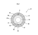
図7に示すように、本実施例2のセラミックヒータ51は、前記実施例1と同様に、円筒形状のヒータ本体53に、円環状でカップ形状(軸方向における一方が凹状となった形状)のフランジ55が外嵌している。Next, Example 2 will be described.
The ceramic heater of Example 2 is the same as that of Example 1 except for the flange structure.
As shown in FIG. 7, the
詳しくは、実施例1と同様に、フランジ55の凹状部分56のガラス溜り部58には、ガラス67が充填され、そのガラス67がヒータ本体53やフランジ55に溶着している。また、フランジ55を構成する金属の熱膨張係数は、ヒータ本体53を構成するセラミックの熱膨張係数及びガラス67の熱膨張係数より大である。さらに、フランジ55の表面にはフランジ55の内部より多くのCrが存在している。しかも、ガラス67の表面のガラス凹状部67aの曲率半径Rは、フランジ55の内径とヒータ本体53の外径とのクリアランスCの1/2〜3/2の範囲である。
Specifically, as in the first embodiment, the
特に、本実施例2では、フランジ55の底部57の貫通孔59の内周面には、セラミック層61の間隙である溝63に嵌り込むような突出部65が形成されている。
これによって、同図の細かい点にて示すガラス67の溶着の際には、溝63の内周面と突出部65の外周面に沿って、溶融したガラス67が流れ込み易いので、ヒータ本体53とフランジ55との間が隙間無くガラス67で充填される。これにより、一層高い気密性が得られるという利点がある。In particular, in the second embodiment, a
As a result, when the
<実験例>
次に、本開示の効果を確認するために行った各種の実験例について説明する。
(実験例1)
本実験例1では、周知のHeリークディテクタを用いて、ガラスの接合部分(溶着部分)のリーク試験を行い、その気密性を調べた。<Experimental example>
Next, various experimental examples performed for confirming the effect of the present disclosure will be described.
(Experimental example 1)
In this Experimental Example 1, a leak test was performed on a glass joining portion (welding portion) using a known He leak detector, and the airtightness thereof was examined.
具体的には、実験に用いる試料として、前記実施例1と同様な構成を有するとともに、フランジの材料として、下記表1に示す材料(試料No.1〜4)を使用して、セラミックヒータを作製した。ガラスは、製造ロット2ロット分にて評価した。 Specifically, the sample used in the experiment has the same configuration as in Example 1, and the material shown in Table 1 below (sample No. 1 to 4) is used as the flange material. Produced. Glass was evaluated in two production lots.
そして、図8に示すように、この試料のセラミックヒータ1のフランジ5の下部にOリング71を配置し、フランジ5を押圧部材73によって下方に押圧する状態とした。なお、セラミックヒータ1の上端は、板材75によって密閉した。
Then, as shown in FIG. 8, an O-
この状態で、セラミックヒータ1の下部が配置された長孔79内より減圧(即ち10-7Paオーダーに減圧)し、セラミックヒータ1の上部を覆う容器77内にHeを導入して、Heリークディテクタによって、Heのリーク量を測定した。In this state, the pressure is reduced from the inside of the
この測定では、各試料は材料毎に5個ずつ作製して、それぞれリーク量を測定した。その結果を、下記表1に記す。
また、比較例として、従来の金属製のフランジを有するセラミックヒータの試料(試料No.5、6)を作製し、同様にリーク量を測定した。この従来のセラミックヒータは、平板から構成されているステンレス製の円環状のフランジにNiメッキを施し、ヒータ本体の外周にメタライズを形成した後にNiメッキを施し、それらをAgろうによってろう付け接合したものである。その結果を同じく下記表1に記す。In this measurement, five samples were prepared for each material, and the amount of leakage was measured. The results are shown in Table 1 below.
Further, as a comparative example, a ceramic heater sample (sample Nos. 5 and 6) having a conventional metal flange was prepared, and the amount of leakage was measured in the same manner. In this conventional ceramic heater, Ni plating is applied to an annular flange made of stainless steel composed of a flat plate, and after the metallization is formed on the outer periphery of the heater body, Ni plating is applied, and these are brazed and joined by Ag brazing. Is. The results are also shown in Table 1 below.

つまり、ろう付け接合したものと同程度の高い気密性を有していることが分かる。
(実験例2)
本実験例2では、ヒータ本体とガラスとの間の接合強度を調べた。That is, it can be seen that the airtightness is as high as that of the brazed joint.
(Experimental example 2)
In Experimental Example 2, the bonding strength between the heater body and the glass was examined.
具体的には、実験に用いる試料(試料No.7)として、前記実施例1と同様な構成を有するとともに、フランジの材料としてSUS304を使用して、セラミックヒータを作製した。 Specifically, as a sample (sample No. 7) used in the experiment, a ceramic heater was manufactured by using SUS304 as a flange material while having the same configuration as in Example 1.
次に、試料のセラミックヒータを垂直に保つとともに、フランジの底面を固定して、セラミック管を上方より打ち抜くように荷重を加えた。そして、そのセラミック管が打ち抜かれる際の荷重(打ち抜き強度)を調べた。 Next, the sample ceramic heater was kept vertical, the bottom surface of the flange was fixed, and a load was applied so as to punch out the ceramic tube from above. Then, the load (punch strength) when the ceramic tube was punched was examined.
また、比較例として、従来のセラミック製のフランジを有するセラミックヒータの試料(試料No.8)を作製し、同様に打ち抜き強度を測定した。この従来のセラミックヒータは、平板から構成されているアルミナ製の正方形型フランジ(一辺30mm×内径φ12mm×厚み4mm)を、その内周面にてガラスによって接合したものである。
Further, as a comparative example, a ceramic heater sample (sample No. 8) having a conventional ceramic flange was prepared, and the punching strength was measured in the same manner. This conventional ceramic heater is formed by joining alumina square flanges (one
それらの結果を、下記表2に記す。 The results are shown in Table 2 below.
(実験例3)
本実験例3では、セラミックヒータの耐酸試験を行った。
具体的には、SUS304、SUS430から構成されているフランジを作製し、1015℃にて30分間加熱を行って、実験に供する試料を作製した。(Experimental example 3)
In Experimental Example 3, an acid resistance test of a ceramic heater was performed.
Specifically, a flange composed of SUS304 and SUS430 was prepared, and heated at 1015 ° C. for 30 minutes to prepare a sample for an experiment.
そして、各試料に対して、10Lの密閉容器中に10%濃度塩酸を1L入れ、各試料を該容器内の中空中に保持し、その塩酸蒸気雰囲気中に100時間放置するという条件にて耐酸実験を行った。 Then, for each sample, 1 L of 10% hydrochloric acid is put in a 10 L sealed container, each sample is held in the hollow inside the container, and the sample is left in the hydrochloric acid vapor atmosphere for 100 hours. The experiment was conducted.
その結果、耐酸試験の前後で、外観及びHeリーク量に差は見られなかった。つまり、本開示で用いるフランジは高い耐酸性を有することが分かった。
(実験例4)
本実験例4では、セラミックヒータの熱衝撃試験を行った。As a result, there was no difference in appearance and He leak amount before and after the acid resistance test. That is, it was found that the flange used in the present disclosure has high acid resistance.
(Experimental example 4)
In Experimental Example 4, a thermal shock test of a ceramic heater was performed.
具体的には、実験に用いる試料(試料No.9)として、前記実施例1と同様な構成を有するとともに、フランジの材料としてSUS304を使用して、セラミックヒータを10個作製した。 Specifically, as a sample (sample No. 9) used for the experiment, ten ceramic heaters were manufactured using SUS304 as the material of the flange while having the same configuration as that of Example 1.
次に、試料のセラミックヒータを下記表3の所定温度毎に5個づつ加熱した後に、それぞれ常温(水温25℃)の水中に投下し、ガラスのクラックの発生状態を調べた。また、水中に投下した各試料に対して、前記実験例1と同様なリーク試験を行った。
Next, after heating 5 ceramic heaters at predetermined temperatures shown in Table 3 below, each sample was dropped into water at room temperature (
その結果を下記表3に記す。なお、クラックの有無は目視で調べ、Heリーク量>1×10⁻⁸Pa・m3/secの場合をリーク不良とした。The results are shown in Table 3 below. The presence or absence of cracks was visually checked, and the case of He leak amount> 1 × 10 −8 Pa · m 3 / sec was regarded as a leak failure.
(実験例5)
本実験例5では、焼成温度によるフランジ表面の組成の変化を調べた。
具体的には、SUS304、SUS430から構成されているフランジを各5個作製し、図9A、図9Bに示すガラスの焼成温度にて30分間加熱を行った。(Experimental example 5)
In Experimental Example 5, the change in the composition of the flange surface with the firing temperature was examined.
Specifically, five flanges each composed of SUS304 and SUS430 were produced and heated at the firing temperature of the glass shown in FIGS. 9A and 9B for 30 minutes.
次に、各試料に対して、エネルギー分散型X線分析(EDS)によって表面の各元素の質量分析を行い、その質量%を求めた。その結果を図9A、図9Bに示す。
この図9A、図9Bから明らかなように、1000℃付近で、Cr、Oの増加が確認された。これは、フランジの表面にCrの酸化物(Crの不動態)が生成したことを示していると考えられる。Next, each sample was subjected to mass analysis of each element on the surface by energy dispersive X-ray analysis (EDS), and the mass% was obtained. The results are shown in FIGS. 9A and 9B.
As is apparent from FIGS. 9A and 9B, increases in Cr and O were confirmed around 1000 ° C. This is considered to indicate that Cr oxide (Cr passivation) was generated on the surface of the flange.
(実験例6)
本実験例6では、シミュレーションによるガラスに加わる表面主応力の変化を調べた。
具体的には、解析ソフトとして、ANSYS APDL15.0を用い、下記の条件にて、本開示の構成のセラミックヒータの応力シミュレーションを行った。(Experimental example 6)
In Experimental Example 6, the change in the principal surface stress applied to the glass by simulation was examined.
Specifically, stress simulation of the ceramic heater having the configuration of the present disclosure was performed using ANSYS APDL 15.0 as analysis software under the following conditions.
<セラミック(ヒータ本体)>
ヤング率:280GPa、ポアソン比:0.3、線膨張係数:6.8ppm/K
<ガラス>
ヤング率:60GPa、ポアソン比:0.3、線膨張係数:6.2ppm/K
<金属(フランジ)>
ヤング率:200GPa、ポアソン比:0.3、線膨張係数:18.1ppm/K
<解析条件>
2次元軸対称モデル
静的解析
693℃(ガラス軟化点)を応力フリー(応力が加わらない状態)とし、25℃に降温した際の応力を評価
図10A−図10Dにそのシミュレーションの結果を示す。図10A−図10Dの灰色部分(斜線部分)が圧縮応力(圧縮残留応力)、濃い灰色部分(細かいメッシュ部分)が引張応力(表面主応力)が残留する範囲である。また、図11及び表4に引張応力(表面主応力)とガラス凹状部の曲率半径Rを示す。なお、図11の表面主応力(HS)とは、ガラスの外周部の表面近傍(例えば図10Cの矢印で示す細かいメッシュ部分)にて加わる引張応力である。<Ceramic (heater body)>
Young's modulus: 280 GPa, Poisson's ratio: 0.3, linear expansion coefficient: 6.8 ppm / K
<Glass>
Young's modulus: 60 GPa, Poisson's ratio: 0.3, linear expansion coefficient: 6.2 ppm / K
<Metal (flange)>
Young's modulus: 200 GPa, Poisson's ratio: 0.3, linear expansion coefficient: 18.1 ppm / K
<Analysis conditions>
Two-dimensional axisymmetric model Static analysis 693 ° C. (glass softening point) is stress-free (no stress is applied), and stress is evaluated when the temperature is lowered to 25 ° C. FIGS. 10A to 10D show the simulation results. In FIG. 10A to FIG. 10D, the gray portion (shaded portion) is a range where compressive stress (compressed residual stress) and the dark gray portion (fine mesh portion) is where tensile stress (surface principal stress) remains. FIG. 11 and Table 4 show the tensile stress (surface principal stress) and the radius of curvature R of the glass concave portion. The surface principal stress (HS) in FIG. 11 is a tensile stress applied near the surface of the outer peripheral portion of the glass (for example, a fine mesh portion indicated by an arrow in FIG. 10C).
ここで、図10Aは、曲率半径Rが1.2mm、ガラス溜り部の幅Xが2.4mm、ガラスの高さH5が3mmの場合を示している。図10Bは、曲率半径Rが1.3mm、ガラス溜り部の幅Xが2.4mm、ガラスの高さH5が3mmの場合を示している。図10Cは、曲率半径Rが2mm、ガラス溜り部の幅Xが2.4mm、ガラスの高さH5が3mmの場合を示している。図10Dは、曲率半径Rが3mm、ガラス溜り部の幅Xが2.4mm、ガラスの高さH5が3mmの場合を示している。 Here, FIG. 10A shows a case where the radius of curvature R is 1.2 mm, the width X of the glass reservoir is 2.4 mm, and the glass height H5 is 3 mm. FIG. 10B shows a case where the radius of curvature R is 1.3 mm, the width X of the glass reservoir is 2.4 mm, and the glass height H5 is 3 mm. FIG. 10C shows a case where the radius of curvature R is 2 mm, the glass reservoir width X is 2.4 mm, and the glass height H5 is 3 mm. FIG. 10D shows a case where the radius of curvature R is 3 mm, the width X of the glass reservoir is 2.4 mm, and the glass height H5 is 3 mm.
なお、クリアランスC=ガラス溜まり部の幅Xは、2.4mmで一定である。 Note that the clearance C = the width X of the glass reservoir portion is constant at 2.4 mm.
また、図10A−図10D及び図11及び表4から、ガラス凹状部の曲率半径Rは、フランジの内径とヒータ本体の外径とのクリアランスCの1/2〜3/2の範囲であれば、表面主応力が小さいこと、即ち、ガラスが破損し難いことが分かる。 Further, from FIGS. 10A to 10D and FIG. 11 and Table 4, the radius of curvature R of the glass concave portion is within a range of 1/2 to 3/2 of the clearance C between the inner diameter of the flange and the outer diameter of the heater body. It can be seen that the surface principal stress is small, that is, the glass is difficult to break.
(実験例7)
本実験例7では、ガラス溶着後のガラス及びヒータ本体に圧縮応力が加わっていることを調べた。(Experimental example 7)
In Experimental Example 7, it was examined that compressive stress was applied to the glass and the heater body after the glass welding.
具体的には、前記実施例1のセラミックヒータと同様な構造の2種の試料を作製した。つまり、フランジの材料としてSUS304又はSUS430を用い、その他の構成は実施例1と同様とした。 Specifically, two types of samples having the same structure as the ceramic heater of Example 1 were prepared. That is, SUS304 or SUS430 was used as the material of the flange, and other configurations were the same as those in Example 1.
そして、各試料に対して、前記図5の側端部5a近傍のフランジ内部の残留応力を、微小X線計測(側傾法、ψ0一定法)にて測定した。なお、測定はそれぞれ6箇所行い、その平均を求めた。
For each sample, the residual stress inside the flange near the
その結果、フランジがSUS304の場合には残留応力は平均337MPa、SUS430の場合には残留応力は平均150MPaであり、いずれも圧縮応力であった。
このように、ガラス及びヒータ本体の熱膨張係数はフランジの熱膨張係数より小さいので、ガラス溶着後のガラス及びヒータ本体に圧縮応力が働いていることは明白である。As a result, the residual stress averaged 337 MPa when the flange was SUS304, and the average residual stress was 150 MPa when the flange was SUS430, both of which were compressive stresses.
Thus, since the thermal expansion coefficients of the glass and the heater main body are smaller than the thermal expansion coefficient of the flange, it is obvious that compressive stress is acting on the glass and the heater main body after glass welding.
以上、本開示の実施例などについて説明したが、本開示は、前記実施例などに限定されるものではなく、種々の態様を採ることができる。
本開示は、温水洗浄便座以外に、ファンヒータ、電気温水器、24時間風呂などに用いられるセラミックヒータと、そのセラミックヒータの製造方法に適用可能である。As mentioned above, although the Example etc. of this indication were explained, this indication is not limited to the above-mentioned example etc., and can take various modes.
The present disclosure can be applied to a ceramic heater used for a fan heater, an electric water heater, a 24-hour bath, and the like, and a method for manufacturing the ceramic heater, in addition to a warm water washing toilet seat.
Claims (10)
前記フランジは、前記ヒータ本体の軸方向における一方の側が該軸方向に沿って凹んだ形状の凹状部分を有し、
前記凹状部分には、ガラスが充填されたガラス溜り部を有するとともに、前記ガラス溜り部に配置されたガラスが、前記フランジ及び前記ヒータ本体に溶着しており、
且つ、前記フランジは、板材から構成され、前記凹状部分を有するカップ形状であるセラミックヒータ。 In a ceramic heater comprising a ceramic cylindrical heater body, and a metal annular flange fitted on the heater body,
The flange has a concave portion having a shape in which one side in the axial direction of the heater body is recessed along the axial direction;
The concave portion has a glass reservoir filled with glass, and the glass disposed in the glass reservoir is welded to the flange and the heater body ,
And the said flange is a ceramic heater which is comprised from a board | plate material and is a cup shape which has the said recessed part .
前記フランジは、前記ヒータ本体の軸方向における一方の側が該軸方向に沿って凹んだ形状の凹状部分を有し、 The flange has a concave portion having a shape in which one side in the axial direction of the heater body is recessed along the axial direction;
前記凹状部分には、ガラスが充填されたガラス溜り部を有するとともに、前記ガラス溜り部に配置されたガラスが、前記フランジ及び前記ヒータ本体に溶着しており、 The concave portion has a glass reservoir filled with glass, and the glass disposed in the glass reservoir is welded to the flange and the heater body,
且つ、前記フランジは、Crを含む金属から構成され、前記フランジの表面のCr含有量は、前記フランジの内部のCr含有量より大であるセラミックヒータ。 And the said flange is comprised from the metal containing Cr, and the Cr content of the surface of the said flange is larger than the Cr content inside the said flange.
前記ヒータ本体に前記フランジを外嵌し、前記フランジのガラス溜り部に前記ガラスの材料を充填し、前記ガラスの材料を溶着温度に加熱して溶融させた後に冷却することによって、前記ガラスを前記フランジと前記ヒータ本体とに溶着させるセラミックヒータの製造方法。 It is a manufacturing method of the ceramic heater according to any one of claims 1 to 8,
The flange is externally fitted to the heater body, the glass reservoir of the flange is filled with the glass material, and the glass material is heated to a welding temperature to be melted and cooled, thereby cooling the glass. A method of manufacturing a ceramic heater to be welded to a flange and the heater body.
Applications Claiming Priority (3)
| Application Number | Priority Date | Filing Date | Title |
|---|---|---|---|
| JP2014223043 | 2014-10-31 | ||
| JP2014223043 | 2014-10-31 | ||
| PCT/JP2015/080567 WO2016068242A1 (en) | 2014-10-31 | 2015-10-29 | Ceramic heater and manufacturing method for same |
Publications (2)
| Publication Number | Publication Date |
|---|---|
| JPWO2016068242A1 JPWO2016068242A1 (en) | 2017-04-27 |
| JP6174821B2 true JP6174821B2 (en) | 2017-08-02 |
Family
ID=55857577
Family Applications (1)
| Application Number | Title | Priority Date | Filing Date |
|---|---|---|---|
| JP2016556628A Active JP6174821B2 (en) | 2014-10-31 | 2015-10-29 | Ceramic heater and manufacturing method thereof |
Country Status (7)
| Country | Link |
|---|---|
| US (1) | US11096250B2 (en) |
| EP (1) | EP3214896B1 (en) |
| JP (1) | JP6174821B2 (en) |
| KR (1) | KR101918427B1 (en) |
| CN (1) | CN107113923B (en) |
| ES (1) | ES2831361T3 (en) |
| WO (1) | WO2016068242A1 (en) |
Cited By (2)
| Publication number | Priority date | Publication date | Assignee | Title |
|---|---|---|---|---|
| US10502823B2 (en) | 2010-10-20 | 2019-12-10 | Robert Bosch Gmbh | Method and device for detecting objects |
| JP2021108256A (en) * | 2019-12-27 | 2021-07-29 | 日本特殊陶業株式会社 | Ceramic heater |
Families Citing this family (3)
| Publication number | Priority date | Publication date | Assignee | Title |
|---|---|---|---|---|
| JP6792539B2 (en) * | 2017-10-31 | 2020-11-25 | 日本特殊陶業株式会社 | Ceramic heater for fluid heating |
| PL424812A1 (en) * | 2018-03-09 | 2019-09-23 | Formaster Spółka Akcyjna | Heating element for tankless heating of liquids and/or generation of steam and the heating element assembly and the device for tankless heating of liquids and/or generation of steam, containing such a heating element |
| JP6860277B2 (en) * | 2018-07-12 | 2021-04-14 | 日本特殊陶業株式会社 | Ceramic heater |
Family Cites Families (22)
| Publication number | Priority date | Publication date | Assignee | Title |
|---|---|---|---|---|
| US1425845A (en) * | 1922-02-23 | 1922-08-15 | Robert B Foster | Flange wrench |
| US2951929A (en) * | 1959-07-09 | 1960-09-06 | Westinghouse Electric Corp | Heating apparatus |
| US3284174A (en) * | 1962-04-16 | 1966-11-08 | Ind Fernand Courtoy Bureau Et | Composite structures made by bonding ceramics, cermets, alloys, heavy alloys and metals of different thermal expansion coefficient |
| US4149910A (en) * | 1975-05-27 | 1979-04-17 | Olin Corporation | Glass or ceramic-to-metal composites or seals involving iron base alloys |
| JPS57200261A (en) * | 1981-06-04 | 1982-12-08 | Matsushita Electric Ind Co Ltd | Ceramic heating body |
| JPH01170846A (en) * | 1987-12-26 | 1989-07-05 | Toyota Motor Corp | Threshold current detection type oxygen concentration sensor |
| JP2557220Y2 (en) * | 1991-03-26 | 1997-12-10 | 京セラ株式会社 | Ceramic heater |
| DE4328718A1 (en) * | 1993-08-26 | 1995-03-02 | Abb Gadelius K K | Heating element |
| JPH0669241U (en) * | 1993-03-04 | 1994-09-27 | 日本特殊陶業株式会社 | Ceramic flange structure |
| JP3285757B2 (en) | 1996-04-17 | 2002-05-27 | 京セラ株式会社 | Ceramic terminal and method of manufacturing the same |
| JPH10220876A (en) * | 1997-02-07 | 1998-08-21 | Matsushita Electric Ind Co Ltd | Water heater |
| JP3588233B2 (en) | 1997-08-29 | 2004-11-10 | 京セラ株式会社 | Ceramic heater |
| US7057140B2 (en) * | 2000-06-30 | 2006-06-06 | Balboa Instruments, Inc. | Water heater |
| US6574426B1 (en) * | 2002-11-18 | 2003-06-03 | Byron Blanco, Jr. | In-line tankless instantaneous electrical resistance water heater |
| JP2005183371A (en) * | 2003-11-28 | 2005-07-07 | Ngk Spark Plug Co Ltd | Ceramic heater and manufacturing method thereof, heat exchange unit, and toilet seat with warm-water washing |
| JP2006059794A (en) | 2004-07-20 | 2006-03-02 | Denso Corp | Ceramic heater |
| JP2006120559A (en) * | 2004-10-25 | 2006-05-11 | Ngk Spark Plug Co Ltd | Ceramic heater, heat exchange unit and manufacturing method of ceramic heater |
| CN101048625A (en) * | 2004-12-20 | 2007-10-03 | 日本特殊陶业株式会社 | Ceramic heater, heat exchange unit, and warm water washing toilet seat |
| JP3940149B2 (en) * | 2005-01-11 | 2007-07-04 | 京セラ株式会社 | Fluid heating device |
| US8294069B2 (en) * | 2007-03-28 | 2012-10-23 | Ngk Insulators, Ltd. | Heating device for heating a wafer |
| CN101456753A (en) | 2007-12-11 | 2009-06-17 | 曾松 | Method for preparing glass solder for ceramic-stainless steel sealing |
| CN203691661U (en) * | 2013-12-24 | 2014-07-02 | 天万电热电器(中山)有限公司 | Anti-creeping electrothermal tube used for electric water heater |
-
2015
- 2015-10-29 ES ES15855716T patent/ES2831361T3/en active Active
- 2015-10-29 US US15/519,586 patent/US11096250B2/en active Active
- 2015-10-29 JP JP2016556628A patent/JP6174821B2/en active Active
- 2015-10-29 WO PCT/JP2015/080567 patent/WO2016068242A1/en active Application Filing
- 2015-10-29 CN CN201580058128.6A patent/CN107113923B/en active Active
- 2015-10-29 KR KR1020177014204A patent/KR101918427B1/en active IP Right Grant
- 2015-10-29 EP EP15855716.5A patent/EP3214896B1/en active Active
Cited By (3)
| Publication number | Priority date | Publication date | Assignee | Title |
|---|---|---|---|---|
| US10502823B2 (en) | 2010-10-20 | 2019-12-10 | Robert Bosch Gmbh | Method and device for detecting objects |
| JP2021108256A (en) * | 2019-12-27 | 2021-07-29 | 日本特殊陶業株式会社 | Ceramic heater |
| JP7249270B2 (en) | 2019-12-27 | 2023-03-30 | 日本特殊陶業株式会社 | ceramic heater |
Also Published As
| Publication number | Publication date |
|---|---|
| EP3214896A1 (en) | 2017-09-06 |
| KR20170076753A (en) | 2017-07-04 |
| CN107113923A (en) | 2017-08-29 |
| CN107113923B (en) | 2021-04-09 |
| EP3214896B1 (en) | 2020-09-02 |
| ES2831361T3 (en) | 2021-06-08 |
| WO2016068242A1 (en) | 2016-05-06 |
| US20170245324A1 (en) | 2017-08-24 |
| EP3214896A4 (en) | 2018-07-04 |
| US11096250B2 (en) | 2021-08-17 |
| JPWO2016068242A1 (en) | 2017-04-27 |
| KR101918427B1 (en) | 2019-01-21 |
Similar Documents
| Publication | Publication Date | Title |
|---|---|---|
| JP6174821B2 (en) | Ceramic heater and manufacturing method thereof | |
| US7696455B2 (en) | Power terminals for ceramic heater and method of making the same | |
| JP5631974B2 (en) | Glass-metal hermetic seal assembly and method for manufacturing glass-metal hermetic seal assembly | |
| CN104511674B (en) | Solder brazing method | |
| EP3282814B1 (en) | Heater | |
| JP6502226B2 (en) | Ceramic heater | |
| CN105810541B (en) | X-ray tube anode assembly | |
| JP6502227B2 (en) | Ceramic heater | |
| JP7444946B2 (en) | heater | |
| KR101212826B1 (en) | Electronic component package, cover body for such electronic component package, cover material for such cover body and method for manufacturing such cover material | |
| JP6860277B2 (en) | Ceramic heater | |
| CN113251838A (en) | Method for manufacturing heat pipe | |
| JP7249270B2 (en) | ceramic heater | |
| JPH0260051A (en) | Hermetical formation of storage battery terminal portion | |
| JP7143256B2 (en) | Wafer mounting table and its manufacturing method | |
| JP2016103345A (en) | Connection structure and heater comprising the same |
Legal Events
| Date | Code | Title | Description |
|---|---|---|---|
| A131 | Notification of reasons for refusal |
Free format text: JAPANESE INTERMEDIATE CODE: A131 Effective date: 20170411 |
|
| A521 | Request for written amendment filed |
Free format text: JAPANESE INTERMEDIATE CODE: A523 Effective date: 20170607 |
|
| TRDD | Decision of grant or rejection written | ||
| A01 | Written decision to grant a patent or to grant a registration (utility model) |
Free format text: JAPANESE INTERMEDIATE CODE: A01 Effective date: 20170613 |
|
| A61 | First payment of annual fees (during grant procedure) |
Free format text: JAPANESE INTERMEDIATE CODE: A61 Effective date: 20170706 |
|
| R150 | Certificate of patent or registration of utility model |
Ref document number: 6174821 Country of ref document: JP Free format text: JAPANESE INTERMEDIATE CODE: R150 |
|
| R250 | Receipt of annual fees |
Free format text: JAPANESE INTERMEDIATE CODE: R250 |
|
| R250 | Receipt of annual fees |
Free format text: JAPANESE INTERMEDIATE CODE: R250 |
|
| R250 | Receipt of annual fees |
Free format text: JAPANESE INTERMEDIATE CODE: R250 |
|
| S531 | Written request for registration of change of domicile |
Free format text: JAPANESE INTERMEDIATE CODE: R313531 |
|
| R350 | Written notification of registration of transfer |
Free format text: JAPANESE INTERMEDIATE CODE: R350 |
|
| R250 | Receipt of annual fees |
Free format text: JAPANESE INTERMEDIATE CODE: R250 |