JP6174263B2 - User terminal and base station - Google Patents
User terminal and base station Download PDFInfo
- Publication number
- JP6174263B2 JP6174263B2 JP2016535959A JP2016535959A JP6174263B2 JP 6174263 B2 JP6174263 B2 JP 6174263B2 JP 2016535959 A JP2016535959 A JP 2016535959A JP 2016535959 A JP2016535959 A JP 2016535959A JP 6174263 B2 JP6174263 B2 JP 6174263B2
- Authority
- JP
- Japan
- Prior art keywords
- communication
- wlan
- cellular
- enb
- data
- Prior art date
- Legal status (The legal status is an assumption and is not a legal conclusion. Google has not performed a legal analysis and makes no representation as to the accuracy of the status listed.)
- Active
Links
- 238000004891 communication Methods 0.000 claims description 351
- 230000001413 cellular effect Effects 0.000 claims description 291
- 230000010267 cellular communication Effects 0.000 claims description 176
- 230000002776 aggregation Effects 0.000 claims description 165
- 238000004220 aggregation Methods 0.000 claims description 165
- 230000005540 biological transmission Effects 0.000 claims description 131
- 238000000034 method Methods 0.000 claims description 52
- 238000005259 measurement Methods 0.000 claims description 12
- 238000012986 modification Methods 0.000 description 36
- 230000004048 modification Effects 0.000 description 36
- 238000010586 diagram Methods 0.000 description 28
- 230000011664 signaling Effects 0.000 description 28
- 230000004044 response Effects 0.000 description 13
- 230000006870 function Effects 0.000 description 12
- 230000008569 process Effects 0.000 description 12
- 230000009977 dual effect Effects 0.000 description 10
- 239000003795 chemical substances by application Substances 0.000 description 8
- 238000005516 engineering process Methods 0.000 description 8
- 238000012545 processing Methods 0.000 description 7
- 238000013468 resource allocation Methods 0.000 description 6
- 238000001228 spectrum Methods 0.000 description 5
- 230000006978 adaptation Effects 0.000 description 4
- 238000006243 chemical reaction Methods 0.000 description 4
- 238000007726 management method Methods 0.000 description 4
- 239000000523 sample Substances 0.000 description 4
- 230000008859 change Effects 0.000 description 3
- 238000012546 transfer Methods 0.000 description 3
- 238000011144 upstream manufacturing Methods 0.000 description 3
- 238000013507 mapping Methods 0.000 description 2
- 101000741965 Homo sapiens Inactive tyrosine-protein kinase PRAG1 Proteins 0.000 description 1
- 102100038659 Inactive tyrosine-protein kinase PRAG1 Human genes 0.000 description 1
- 230000002457 bidirectional effect Effects 0.000 description 1
- 230000006835 compression Effects 0.000 description 1
- 238000007906 compression Methods 0.000 description 1
- 230000006837 decompression Effects 0.000 description 1
- 230000007423 decrease Effects 0.000 description 1
- 238000001514 detection method Methods 0.000 description 1
- 230000002349 favourable effect Effects 0.000 description 1
- 230000007774 longterm Effects 0.000 description 1
- 230000007257 malfunction Effects 0.000 description 1
- 238000004519 manufacturing process Methods 0.000 description 1
- 238000010295 mobile communication Methods 0.000 description 1
- 238000000060 site-specific infrared dichroism spectroscopy Methods 0.000 description 1
- 238000003860 storage Methods 0.000 description 1
Images


Classifications
-
- H—ELECTRICITY
- H04—ELECTRIC COMMUNICATION TECHNIQUE
- H04W—WIRELESS COMMUNICATION NETWORKS
- H04W36/00—Hand-off or reselection arrangements
- H04W36/14—Reselecting a network or an air interface
- H04W36/144—Reselecting a network or an air interface over a different radio air interface technology
- H04W36/1446—Reselecting a network or an air interface over a different radio air interface technology wherein at least one of the networks is unlicensed
-
- H—ELECTRICITY
- H04—ELECTRIC COMMUNICATION TECHNIQUE
- H04W—WIRELESS COMMUNICATION NETWORKS
- H04W76/00—Connection management
- H04W76/30—Connection release
- H04W76/34—Selective release of ongoing connections
-
- H—ELECTRICITY
- H04—ELECTRIC COMMUNICATION TECHNIQUE
- H04L—TRANSMISSION OF DIGITAL INFORMATION, e.g. TELEGRAPHIC COMMUNICATION
- H04L45/00—Routing or path finding of packets in data switching networks
- H04L45/24—Multipath
- H04L45/245—Link aggregation, e.g. trunking
-
- H—ELECTRICITY
- H04—ELECTRIC COMMUNICATION TECHNIQUE
- H04W—WIRELESS COMMUNICATION NETWORKS
- H04W24/00—Supervisory, monitoring or testing arrangements
- H04W24/10—Scheduling measurement reports ; Arrangements for measurement reports
-
- H—ELECTRICITY
- H04—ELECTRIC COMMUNICATION TECHNIQUE
- H04W—WIRELESS COMMUNICATION NETWORKS
- H04W36/00—Hand-off or reselection arrangements
- H04W36/14—Reselecting a network or an air interface
-
- H—ELECTRICITY
- H04—ELECTRIC COMMUNICATION TECHNIQUE
- H04W—WIRELESS COMMUNICATION NETWORKS
- H04W72/00—Local resource management
- H04W72/04—Wireless resource allocation
-
- H—ELECTRICITY
- H04—ELECTRIC COMMUNICATION TECHNIQUE
- H04W—WIRELESS COMMUNICATION NETWORKS
- H04W84/00—Network topologies
- H04W84/02—Hierarchically pre-organised networks, e.g. paging networks, cellular networks, WLAN [Wireless Local Area Network] or WLL [Wireless Local Loop]
- H04W84/10—Small scale networks; Flat hierarchical networks
- H04W84/12—WLAN [Wireless Local Area Networks]
-
- H—ELECTRICITY
- H04—ELECTRIC COMMUNICATION TECHNIQUE
- H04W—WIRELESS COMMUNICATION NETWORKS
- H04W88/00—Devices specially adapted for wireless communication networks, e.g. terminals, base stations or access point devices
- H04W88/02—Terminal devices
- H04W88/06—Terminal devices adapted for operation in multiple networks or having at least two operational modes, e.g. multi-mode terminals
-
- H—ELECTRICITY
- H04—ELECTRIC COMMUNICATION TECHNIQUE
- H04W—WIRELESS COMMUNICATION NETWORKS
- H04W88/00—Devices specially adapted for wireless communication networks, e.g. terminals, base stations or access point devices
- H04W88/08—Access point devices
- H04W88/10—Access point devices adapted for operation in multiple networks, e.g. multi-mode access points
Description
本出願は、セルラ・WLAN無線インターワーキング技術をサポートするユーザ端末及び基地局に関する。 The present application relates to a user terminal and a base station that support cellular WLAN wireless interworking technology.
セルラ通信技術の標準化プロジェクトである3GPP(3rd Generation Partnership Project)で仕様が策定されているLTE(Long Term Evolution)は、リリース12以降において、セルラ・WLAN無線インターワーキング技術をサポートする(非特許文献1及び2参照)。
LTE (Long Term Evolution) whose specifications are defined by 3GPP (3rd Generation Partnership Project), a standardization project for cellular communication technology, supports cellular / WLAN wireless interworking technology in
このような技術では、ユーザ端末は、セルラ受信信号の受信電力又は受信品質に関する判定条件及びWLANに関する判定条件に基づいて、自ユーザ端末のトラフィックをセルラ通信とWLAN通信との間で切り替える端末主導型の切り替え制御を行う。判定条件は、セルラネットワーク(RAN:Radio Access Network)から指定される閾値(RAN assistance parameters)により定められる。 In such a technique, the user terminal switches the traffic of the own user terminal between the cellular communication and the WLAN communication based on the determination condition regarding the reception power or reception quality of the cellular reception signal and the determination condition regarding the WLAN. Switching control is performed. The determination condition is determined by a threshold value (RAN assistance parameters) specified from a cellular network (RAN: Radio Access Network).
また、セルラ・WLAN無線インターワーキング技術を高度化するために、同一データベアラに属するトラフィックをセルラ通信及びWLAN通信を併用して送受信する技術(以下、「セルラ・WLANアグリゲーション」という)の提案がなされている(非特許文献3参照)。 In addition, in order to advance cellular / WLAN wireless interworking technology, a technology for transmitting and receiving traffic belonging to the same data bearer by using both cellular communication and WLAN communication (hereinafter referred to as “cellular / WLAN aggregation”) has been proposed. (See Non-Patent Document 3).
そこで、本出願は、セルラ・WLANアグリゲーションが導入された場合に効率的な制御を実現可能なユーザ端末及び基地局を提供することを目的とする。 Therefore, an object of the present application is to provide a user terminal and a base station capable of realizing efficient control when cellular / WLAN aggregation is introduced.
一つの実施形態に係るユーザ端末は、セルラ通信及びWLAN通信をサポートする。前記ユーザ端末は、同一の又は異なるデータベアラに属するトラフィックを前記セルラ通信及び前記WLAN通信を併用して送受信するセルラ・WLANアグリゲーションを実行中に、前記WLAN通信における無線リンク障害が発生したと判断する制御部を備える。 A user terminal according to one embodiment supports cellular communication and WLAN communication. The user terminal determines that a radio link failure has occurred in the WLAN communication while performing cellular / WLAN aggregation in which traffic belonging to the same or different data bearer is transmitted and received in combination with the cellular communication and the WLAN communication. A control unit is provided.
[実施形態の概要]
第9実施形態に係るユーザ端末は、セルラ通信及びWLAN通信をサポートする。前記ユーザ端末は、同一の又は異なるデータベアラに属するトラフィックを前記セルラ通信及び前記WLAN通信を併用して送受信するセルラ・WLANアグリゲーションを実行中に、前記WLAN通信における無線リンク障害が発生したと判断する制御部を備える。[Outline of Embodiment]
The user terminal according to the ninth embodiment supports cellular communication and WLAN communication. The user terminal determines that a radio link failure has occurred in the WLAN communication while performing cellular / WLAN aggregation in which traffic belonging to the same or different data bearer is transmitted and received in combination with the cellular communication and the WLAN communication. A control unit is provided.
第9実施形態では、前記制御部は、所定の判定条件に基づいて、前記WLAN通信から前記セルラ通信に切り替えるか否かの切り替え判定を行う。前記制御部は、前記所定の判定条件が満たされた場合、前記WLAN通信における無線リンク障害が発生したと判断する。 In the ninth embodiment, the control unit determines whether to switch from the WLAN communication to the cellular communication based on a predetermined determination condition. The control unit determines that a radio link failure has occurred in the WLAN communication when the predetermined determination condition is satisfied.
第9実施形態では、前記制御部は、前記WLAN通信における無線リンク障害が発生したと判断した場合、当該無線リンク障害に関する無線リンク障害報告を前記セルラ通信により基地局に送信する。 In the ninth embodiment, when the control unit determines that a radio link failure has occurred in the WLAN communication, the control unit transmits a radio link failure report related to the radio link failure to the base station through the cellular communication.
第9実施形態では、前記制御部が前記WLAN通信における無線リンク障害が発生したと判断した場合、当該無線リンク障害に関する無線リンク障害報告を前記セルラ通信により基地局に送信する送信部をさらに備える。 In 9th Embodiment, when the said control part judges that the radio link failure in the said WLAN communication has generate | occur | produced, the transmission part which further transmits the radio link failure report regarding the said radio link failure to the base station by the said cellular communication is further provided.
第9実施形態では、前記送信部は、前記WLAN通信における周波数帯の干渉状況、前記WLAN通信における送受信の失敗、前記WLAN通信を行っているアクセスポイントからの無線信号の受信強度、及び、前記アクセスポイントとの接続の断絶、の少なくともいずれか一つを理由として含む前記無線リンク障害報告を送信する。 In the ninth embodiment, the transmission unit includes an interference situation of a frequency band in the WLAN communication, a failure in transmission / reception in the WLAN communication, a reception strength of a radio signal from an access point performing the WLAN communication, and the access The radio link failure report including at least one of the reasons for disconnection from the point is transmitted.
第9実施形態に係る基地局は、セルラ通信及びWLAN通信をサポートするセルラ・WLAN一体型である、又は、前記WLAN通信をサポートするアクセスポイントと接続し前記セルラ通信をサポートする基地局である。前記基地局は、同一の又は異なるデータベアラに属するデータを前記セルラ通信及び前記WLAN通信を併用して送受信するセルラ・WLANアグリゲーションを制御する制御部と、前記セルラ・WLANアグリゲーションを制御中に、前記セルラ・WLANアグリゲーションを実行するユーザ端末又は前記アクセスポイントから、前記WLAN通信における無線リンク障害が発生したことを示す無線リンク障害報告を受信する受信部と、を備える。 The base station according to the ninth embodiment is a cellular / WLAN integrated type that supports cellular communication and WLAN communication, or is a base station that supports the cellular communication by connecting to an access point that supports the WLAN communication. The base station controls cellular / WLAN aggregation that transmits / receives data belonging to the same or different data bearer by using both the cellular communication and the WLAN communication, and controlling the cellular / WLAN aggregation, A reception unit that receives a radio link failure report indicating that a radio link failure has occurred in the WLAN communication from a user terminal that performs cellular / WLAN aggregation or the access point.
第9実施形態では、前記制御部は、前記無線リンク障害報告に基づいて、前記セルラ・WLANアグリゲーションにおける前記WLAN通信用のデータベアラを解放するため情報、又は、前記セルラ・WLANアグリゲーションにおける前記WLAN通信用のデータベアラを別のデータベアラに変更するための情報を前記アクセスポイント又は前記アクセスポイントを制御するノードに送信する制御を行う。 In 9th Embodiment, the said control part is information for releasing the data bearer for the said WLAN communication in the said cellular and WLAN aggregation based on the said radio link failure report, or the said WLAN communication in the said cellular and WLAN aggregation Control for transmitting the information for changing the data bearer to another data bearer to the access point or a node controlling the access point.
第9実施形態では、前記無線リンク障害報告は、前記無線リンク障害が発生したと判断された理由及び前記WLAN通信に関する最新の測定結果少なくともいずれかの情報を含む。 In the ninth embodiment, the radio link failure report includes at least one of the reason why it is determined that the radio link failure has occurred and the latest measurement result regarding the WLAN communication.
第9実施形態に係る基地局は、前記無線リンク障害報告を前記ユーザ端末から受信した場合、前記WLAN通信における無線リンク障害が発生したことを示す情報を前記アクセスポイントに送信する送信部をさらに備える。 The base station according to the ninth embodiment further includes a transmission unit that transmits information indicating that a radio link failure has occurred in the WLAN communication to the access point when the radio link failure report is received from the user terminal. .
第9実施形態に係る基地局は、前記セルラ・WLANアグリゲーションにおいて前記WLAN通信により前記ユーザ端末に送信予定の下りデータを前記アクセスポイント又は前記アクセスポイントを制御するノードに送信する送信部をさらに備える。前記受信部は、前記無線リンク障害報告に基づいて、前記下りデータのうち未送信の下りデータを前記アクセスポイントから受信する。 The base station according to the ninth embodiment further includes a transmission unit that transmits downlink data scheduled to be transmitted to the user terminal by the WLAN communication in the cellular / WLAN aggregation to the access point or a node that controls the access point. The reception unit receives untransmitted downlink data from the access point based on the radio link failure report.
第9実施形態では、前記制御部は、前記無線リンク障害報告に基づいて、前記未送信の下りデータの送信要求を前記アクセスポイントに送信する制御を行う。前記受信部は、前記送信要求を受信した前記アクセスポイントから、前記未送信の下りデータを受信する。 In the ninth embodiment, the control unit performs control to transmit a transmission request for the untransmitted downlink data to the access point based on the radio link failure report. The reception unit receives the untransmitted downlink data from the access point that has received the transmission request.
第9実施形態では、前記制御部は、前記アクセスポイントに送信済みの前記下りデータを削除済みの場合に、前記未送信の下りデータの送信要求を前記アクセスポイント又は前記アクセスポイントを制御するノードに送信する制御を行う。 In the ninth embodiment, when the downlink data transmitted to the access point has been deleted, the control unit sends a transmission request for the untransmitted downlink data to the access point or a node that controls the access point. Control to send.
第1実施形態に係るユーザ端末は、セルラ通信及びWLAN通信をサポートする。前記ユーザ端末は、セルラ受信信号の受信電力又は受信品質に関する第1の判定条件及びWLANに関する第2の判定条件に基づいて、前記セルラ通信から前記WLAN通信に切り替えるか否かの切り替え判定を行う制御部を備える。前記制御部は、セルラネットワークから特定のWLAN識別子が指定されており、かつ、前記特定のWLAN識別子を含むWLAN受信信号を検出した場合、前記第1の判定条件に基づくことなく、前記第2の判定条件に基づいて前記切り替え判定を行う。 The user terminal according to the first embodiment supports cellular communication and WLAN communication. The user terminal performs a switching determination as to whether or not to switch from the cellular communication to the WLAN communication based on a first determination condition relating to reception power or reception quality of a cellular reception signal and a second determination condition relating to WLAN. A part. The control unit, when a specific WLAN identifier is specified from a cellular network and a WLAN reception signal including the specific WLAN identifier is detected, the second determination unit is not based on the first determination condition. The switching determination is performed based on the determination condition.
第1実施形態では、前記特定のWLAN識別子は、前記セルラ通信及び前記WLAN通信をサポートするセルラ・WLAN一体型の基地局に割り当てられているWLAN識別子である。 In the first embodiment, the specific WLAN identifier is a WLAN identifier assigned to a cellular / WLAN-integrated base station that supports the cellular communication and the WLAN communication.
第1実施形態では、前記セルラ通信及び前記WLAN通信をサポートするセルラ・WLAN一体型の基地局に割り当てられている特定のセル識別子が前記セルラネットワークから通知されており、自ユーザ端末のWLAN通信機能がオフである場合、前記制御部は、前記特定のセル識別子を含むセルラ受信信号を検出したことに応じて、前記WLAN通信機能をオンにする。 In the first embodiment, a specific cell identifier assigned to a cellular / WLAN integrated base station that supports the cellular communication and the WLAN communication is notified from the cellular network, and the WLAN communication function of the own user terminal Is turned off, the control unit turns on the WLAN communication function in response to detecting a cellular reception signal including the specific cell identifier.
第2実施形態に係るユーザ端末は、セルラ通信及びWLAN通信をサポートする。前記ユーザ端末は、セルラ受信信号の受信電力又は受信品質を、セルラネットワークから指定された閾値と比較することにより、前記セルラ通信から前記WLAN通信に切り替えるか否かの切り替え判定を行う制御部を備える。前記制御部は、WLAN識別子ごとに前記閾値が指定されている場合、WLAN受信信号に含まれるWLAN識別子に対応する前記閾値を前記切り替え判定に使用する。 The user terminal according to the second embodiment supports cellular communication and WLAN communication. The user terminal includes a control unit that determines whether to switch from the cellular communication to the WLAN communication by comparing the reception power or reception quality of the cellular reception signal with a threshold specified by a cellular network. . When the threshold is specified for each WLAN identifier, the control unit uses the threshold corresponding to the WLAN identifier included in the WLAN reception signal for the switching determination.
第2実施形態に係る基地局は、セルラ受信信号の受信電力又は受信品質を、セルラネットワークから指定された閾値と比較することにより、セルラ通信からWLAN通信に切り替えるか否かの切り替え判定を行うユーザ端末が在圏するセルを管理する。前記基地局は、前記切り替え判定に使用される前記閾値をWLAN識別子ごとに指定する制御部を備える。 The base station according to the second embodiment compares the reception power or reception quality of the cellular reception signal with a threshold specified by the cellular network, thereby performing a switching determination as to whether or not to switch from the cellular communication to the WLAN communication. Manage the cell where the terminal is located. The base station includes a control unit that designates the threshold value used for the switching determination for each WLAN identifier.
第3実施形態に係るユーザ端末は、セルラ通信及びWLAN通信をサポートする。前記ユーザ端末は、自ユーザ端末のトラフィックを前記セルラ通信と前記WLAN通信との間で切り替える端末主導型の切り替え制御を行う制御部を備える。前記制御部は、セルラネットワークから特定のWLAN識別子が指定されている場合、前記特定のWLAN識別子について前記端末主導型の切り替え制御を無効とする。前記特定のWLAN識別子は、同一の又は異なるデータベアラに属するトラフィックを前記セルラ通信及び前記WLAN通信を併用して送受信するセルラ・WLANアグリゲーションをサポートするノードに割り当てられているWLAN識別子である。 The user terminal according to the third embodiment supports cellular communication and WLAN communication. The user terminal includes a control unit that performs terminal-driven switching control for switching the traffic of the user terminal between the cellular communication and the WLAN communication. The control unit disables the terminal-driven switching control for the specific WLAN identifier when a specific WLAN identifier is designated from the cellular network. The specific WLAN identifier is a WLAN identifier assigned to a node that supports cellular / WLAN aggregation that transmits and receives traffic belonging to the same or different data bearer by using both the cellular communication and the WLAN communication.
第3実施形態では、前記特定のWLAN識別子は、前記セルラネットワークから前記ユーザ端末に送信されるWLAN測定指示に含まれる。 In the third embodiment, the specific WLAN identifier is included in a WLAN measurement instruction transmitted from the cellular network to the user terminal.
第4実施形態に係るユーザ端末は、セルラ通信及びWLAN通信をサポートする。前記ユーザ端末は、自ユーザ端末のトラフィックを前記セルラ通信と前記WLAN通信との間で切り替える端末主導型の切り替え制御を行う制御部を備える。前記制御部は、同一の又は異なるデータベアラに属するトラフィックを前記セルラ通信及び前記WLAN通信を併用して送受信するセルラ・WLANアグリゲーションを実行中である場合、前記端末主導型の切り替え制御を無効とする。 The user terminal according to the fourth embodiment supports cellular communication and WLAN communication. The user terminal includes a control unit that performs terminal-driven switching control for switching the traffic of the user terminal between the cellular communication and the WLAN communication. The control unit invalidates the terminal-driven switching control when the cellular / WLAN aggregation is performed to transmit / receive traffic belonging to the same or different data bearer by using both the cellular communication and the WLAN communication. .
第5実施形態に係るユーザ端末は、セルラ通信及びWLAN通信をサポートする。前記ユーザ端末は、同一の又は異なるデータベアラに属するトラフィックを前記セルラ通信及び前記WLAN通信を併用して送受信するセルラ・WLANアグリゲーションを実行する制御部を備える。前記制御部は、前記セルラ通信のMAC層以下の第1のエンティティと、前記WLAN通信のMAC層以下の第2のエンティティと、前記セルラ通信のRLC層以上の第3のエンティティと、を含む。前記セルラ・WLANアグリゲーションにおいて、前記第3のエンティティは、前記第2のエンティティを介さずに、前記第1のエンティティを介して制御信号を基地局と送受信する。 The user terminal according to the fifth embodiment supports cellular communication and WLAN communication. The user terminal includes a control unit that performs cellular / WLAN aggregation that transmits and receives traffic belonging to the same or different data bearer by using both the cellular communication and the WLAN communication. The control unit includes a first entity below the MAC layer of the cellular communication, a second entity below the MAC layer of the WLAN communication, and a third entity above the RLC layer of the cellular communication. In the cellular / WLAN aggregation, the third entity transmits / receives a control signal to / from a base station via the first entity without passing through the second entity.
第5実施形態に係る基地局は、セルラ通信及びWLAN通信をサポートするセルラ・WLAN一体型の基地局である。前記基地局は、同一の又は異なるデータベアラに属するトラフィックを前記セルラ通信及び前記WLAN通信を併用して送受信するセルラ・WLANアグリゲーションを実行する制御部を備える。前記制御部は、前記セルラ通信のMAC層以下の第1のエンティティと、前記WLAN通信のMAC層以下の第2のエンティティと、前記セルラ通信のRLC層以上の第3のエンティティと、を含む。前記セルラ・WLANアグリゲーションにおいて、前記第3のエンティティは、前記第2のエンティティを介さずに、前記第1のエンティティを介して制御信号をユーザ端末と送受信する。 The base station according to the fifth embodiment is a cellular / WLAN integrated base station that supports cellular communication and WLAN communication. The base station includes a control unit that performs cellular / WLAN aggregation that transmits and receives traffic belonging to the same or different data bearer by using both the cellular communication and the WLAN communication. The control unit includes a first entity below the MAC layer of the cellular communication, a second entity below the MAC layer of the WLAN communication, and a third entity above the RLC layer of the cellular communication. In the cellular / WLAN aggregation, the third entity transmits / receives a control signal to / from a user terminal via the first entity without passing through the second entity.
第6実施形態及びその他実施形態に係る基地局は、ユーザ端末と接続可能な基地局である。前記基地局は、同一の又は異なるデータベアラに属するトラフィックを、前記基地局と前記ユーザ端末との間の第1の通信、及び、前記基地局と直接的なインターフェイスを介して接続する他のノードと前記ユーザ端末との間の第2の通信、を併用して送受信する通信方式を実行する制御部と、前記ユーザ端末の未送信データ量を示すバッファ状態報告を前記ユーザ端末から受信する受信部と、を備える。前記制御部は、前記バッファ状態報告に基づいて、前記第1の通信の上りリンクにおいて前記ユーザ端末に割り当てる無線リソースと前記第2の通信の上りリンクにおいて前記ユーザ端末に割り当てる無線リソースとの比率を決定する。 The base station according to the sixth embodiment and other embodiments is a base station that can be connected to a user terminal. The base station connects the traffic belonging to the same or different data bearer via the first communication between the base station and the user terminal and the base station via a direct interface. A control unit that executes a communication method for transmitting and receiving the second communication between the user terminal and the user terminal, and a receiving unit that receives a buffer status report indicating an untransmitted data amount of the user terminal from the user terminal And comprising. The control unit, based on the buffer status report, determines a ratio between a radio resource allocated to the user terminal in the uplink of the first communication and a radio resource allocated to the user terminal in the uplink of the second communication. decide.
第6実施形態では、前記通信方式は、前記トラフィックを、前記第1通信であるセルラ通信、及び、前記他ノードであるアクセスポイントと前記ユーザ端末との間の前記第2の通信であるWLAN通信、を併用して送受信するセルラ・WLANアグリゲーションである。 In the sixth embodiment, the communication method uses the traffic as cellular communication as the first communication and WLAN communication as the second communication between the access point as the other node and the user terminal. Is a cellular / WLAN aggregation that transmits and receives in combination.
その他実施形態では、前記通信方式は、前記トラフィックを、前記第1通信である第1のセルラ通信、及び、前記他ノードである他の基地局と前記ユーザ端末との間の前記第2の通信である第2のセルラ通信、を併用して送受信する二重接続方式である。 In another embodiment, the communication method uses the traffic as a first cellular communication that is the first communication, and the second communication between the other base station that is the other node and the user terminal. This is a double connection method for transmitting and receiving in combination with the second cellular communication.
第6実施形態に係る基地局は、セルラ通信及びWLAN通信をサポートするセルラ・WLAN一体型の基地局である。前記基地局は、同一の又は異なるデータベアラに属するトラフィックを前記セルラ通信及び前記WLAN通信を併用して送受信するセルラ・WLANアグリゲーションを実行する制御部と、ユーザ端末の未送信データ量を示すバッファ状態報告を前記ユーザ端末から受信する受信部と、を備える。前記制御部は、前記バッファ状態報告に基づいて、前記セルラ通信の上りリンクにおいて前記ユーザ端末に割り当てる無線リソースと前記WLAN通信の上りリンクにおいて前記ユーザ端末に割り当てる無線リソースとの比率を決定する。 The base station according to the sixth embodiment is a cellular / WLAN integrated base station that supports cellular communication and WLAN communication. The base station includes a control unit that performs cellular / WLAN aggregation that transmits and receives traffic belonging to the same or different data bearer in combination with the cellular communication and the WLAN communication, and a buffer state that indicates an untransmitted data amount of the user terminal A receiving unit that receives a report from the user terminal. The control unit determines a ratio between a radio resource allocated to the user terminal in the uplink of the cellular communication and a radio resource allocated to the user terminal in the uplink of the WLAN communication based on the buffer status report.
第6実施形態及びその他実施形態に係るユーザ端末は、基地局と接続可能なユーザ端末である。前記ユーザ端末は、同一の又は異なるデータベアラに属するトラフィックを、前記基地局と前記ユーザ端末との間の第1の通信、及び、前記基地局と直接的なインターフェイスを介して接続する他のノードと前記ユーザ端末との間の第2の通信、を併用して送受信する通信方式を実行する制御部と、前記第1の通信における未送信データを記憶する第1バッファとは別に、前記第2の通信における未送信データを記憶する第2バッファを有する記憶部と、前記通信方式を実行中に、前記第1バッファ及び前記第2バッファに基づいて、未送信データ量を示すバッファ状態報告を前記基地局に送信する送信部と、を備える。 User terminals according to the sixth embodiment and other embodiments are user terminals connectable to a base station. The user terminal connects the traffic belonging to the same or different data bearer via the first communication between the base station and the user terminal and the base station via a direct interface. In addition to the control unit that executes a communication method for transmitting and receiving the second communication between the user terminal and the user terminal, and the first buffer that stores untransmitted data in the first communication, A storage unit having a second buffer for storing untransmitted data in the communication, and a buffer status report indicating the amount of untransmitted data based on the first buffer and the second buffer during execution of the communication method. A transmission unit for transmitting to the base station.
第6実施形態及びその他実施形態では、前記送信部は、前記第1の通信及び前記第2の通信の上りリンクにおける送信データ量に対する前記第1の通信の上りリンクにおける送信データ量の比率に応じて補正された前記第1の通信における未送信データ量を示す前記バッファ状態報告を前記基地局に送信する。
In 6th Embodiment and other embodiment, the said transmission part respond | corresponds with ratio of the transmission data amount in the uplink of said 1st communication with respect to the transmission data amount in the uplink of said 1st communication and said 2nd communication The buffer status report indicating the amount of untransmitted data in the first communication corrected in
第6実施形態及びその他実施形態では、前記送信部は、前記第1の通信における未送信データ量及び前記第2の通信における未送信データ量を示す前記バッファ状態報告を前記基地局に送信する。 In the sixth embodiment and other embodiments, the transmission unit transmits the buffer status report indicating the untransmitted data amount in the first communication and the untransmitted data amount in the second communication to the base station.
第6実施形態では、前記通信方式は、前記トラフィックを、前記第1の通信であるセルラ通信、及び、前記他ノードであるアクセスポイントと前記ユーザ端末との間の前記第2の通信であるWLAN通信、を併用して送受信するセルラ・WLANアグリゲーションである。 In the sixth embodiment, the communication method is the WLAN that is the second communication between the user terminal and the cellular communication that is the first communication, and the access point that is the other node. This is a cellular / WLAN aggregation that transmits and receives data together.
その他実施形態では、前記通信方式は、前記トラフィックを、前記第1の通信である第1のセルラ通信、及び、前記他ノードである他の基地局と前記ユーザ端末との間の前記第2の通信である第2のセルラ通信、を併用して送受信する二重接続方式である。 In another embodiment, the communication method uses the traffic as the first cellular communication as the first communication and the second terminal between the other base station as the other node and the user terminal. This is a double connection method in which the second cellular communication that is communication is used in combination for transmission and reception.
第6実施形態及びその他実施形態に係る基地局は、ユーザ端末と接続可能な基地局である。前記基地局は、同一の又は異なるデータベアラに属するトラフィックを、前記基地局と前記ユーザ端末との間の第1の通信、及び、前記基地局と直接的なインターフェイスを介して接続する他のノードと前記ユーザ端末との間の第2の通信、を併用して送受信する通信方式を実行する制御部と、前記ユーザ端末に対して、前記第1の通信による前記ユーザ端末の送信データ量と前記第2の通信による前記ユーザ端末の送信データ量との比率である上り送信比率を設定する制御情報を送信する送信部と、を備える。 The base station according to the sixth embodiment and other embodiments is a base station that can be connected to a user terminal. The base station connects the traffic belonging to the same or different data bearer via the first communication between the base station and the user terminal and the base station via a direct interface. And a second communication between the user terminal and a control unit that executes a communication method for transmitting and receiving in combination, and for the user terminal, the amount of transmission data of the user terminal by the first communication and the user terminal A transmission unit configured to transmit control information for setting an uplink transmission ratio that is a ratio with a transmission data amount of the user terminal by the second communication.
第6実施形態及びその他実施形態では、前記制御部は、前記アクセスポイントのスループットを推定可能な情報に基づいて、前記上り送信比率を決定する。 In 6th Embodiment and other embodiment, the said control part determines the said uplink transmission ratio based on the information which can estimate the throughput of the said access point.
第6実施形態及びその他実施形態では、前記送信部は、前記基地局から受信した前記制御情報に基づいて前記上り送信比率を設定する第1モードと、前記上り送信比率を自律的に設定する第2モードと、を切り替え可能なユーザ端末に対して、前記第1モードと前記第2モードとの切り替えに関する制御情報を送信する。 In 6th Embodiment and other embodiment, the said transmission part sets the said uplink transmission ratio based on the said control information received from the said base station, and the 1st mode which sets the said uplink transmission ratio autonomously Control information related to switching between the first mode and the second mode is transmitted to a user terminal capable of switching between two modes.
第6実施形態では、前記通信方式は、前記トラフィックを、前記第1通信であるセルラ通信、及び、前記他ノードであるアクセスポイントと前記ユーザ端末との間の前記第2の通信であるWLAN通信、を併用して送受信するセルラ・WLANアグリゲーションである。 In the sixth embodiment, the communication method uses the traffic as cellular communication as the first communication and WLAN communication as the second communication between the access point as the other node and the user terminal. Is a cellular / WLAN aggregation that transmits and receives in combination.
その他実施形態では、前記通信方式は、前記トラフィックを、前記第1通信である第1のセルラ通信、及び、前記他ノードである他の基地局と前記ユーザ端末との間の前記第2の通信である第2のセルラ通信、を併用して送受信する二重接続方式である。 In another embodiment, the communication method uses the traffic as a first cellular communication that is the first communication, and the second communication between the other base station that is the other node and the user terminal. This is a double connection method for transmitting and receiving in combination with the second cellular communication.
第6実施形態及びその他実施形態に係るユーザ端末は、基地局と接続可能なユーザ端末である。前記ユーザ端末は、同一の又は異なるデータベアラに属するトラフィックを、前記基地局と前記ユーザ端末との間の第1の通信、及び、前記基地局と直接的なインターフェイスを介して接続する他のノードとの前記ユーザ端末との間の第2の通信、を併用して送受信する通信方式を実行する制御部を備える。前記制御部は、前記通信方式を実行中に、前記第1の通信の下りリンクにおいて受信に成功したデータユニットの数と前記第2の通信の下りリンクにおいて受信に成功したデータユニットの数とに基づいて、前記第1の通信の上りリンクにおける送信データ量と前記第2の通信の上りリンクにおける送信データ量との比率を決定する。 User terminals according to the sixth embodiment and other embodiments are user terminals connectable to a base station. The user terminal connects the traffic belonging to the same or different data bearer via the first communication between the base station and the user terminal and the base station via a direct interface. And a second communication with the user terminal. The control unit executes a communication method for transmitting and receiving the second communication with the user terminal. The control unit, while executing the communication method, to the number of data units successfully received in the downlink of the first communication and the number of data units successfully received in the downlink of the second communication Based on this, a ratio between the amount of transmission data in the uplink of the first communication and the amount of transmission data in the uplink of the second communication is determined.
第6実施形態及びその他実施形態に係る基地局は、ユーザ端末と接続可能な基地局である。前記基地局は、同一の又は異なるデータベアラに属するトラフィックを、前記基地局と前記ユーザ端末との間の第1の通信、及び、前記基地局と直接的なインターフェイスを介して接続する他のノードとの前記ユーザ端末との間の第2の通信、を併用して送受信する通信方式を実行する制御部を備える。前記制御部は、前記ユーザ端末が前記通信方式を実行中である場合、前記第1の通信によって受信に成功した前記ユーザ端末からのデータユニットの数と前記第2の通信によって受信に成功した前記ユーザ端末からのデータユニットの数とに基づいて、前記第1の通信による前記ユーザ端末への送信データ量と前記第2の通信による前記ユーザ端末への送信データ量との比率を決定する。 The base station according to the sixth embodiment and other embodiments is a base station that can be connected to a user terminal. The base station connects the traffic belonging to the same or different data bearer via the first communication between the base station and the user terminal and the base station via a direct interface. And a second communication with the user terminal. The control unit executes a communication method for transmitting and receiving the second communication with the user terminal. The control unit, when the user terminal is executing the communication method, the number of data units from the user terminal successfully received by the first communication and the successful reception by the second communication Based on the number of data units from the user terminal, a ratio between the amount of data transmitted to the user terminal by the first communication and the amount of data transmitted to the user terminal by the second communication is determined.
第7実施形態に係るユーザ端末は、セルラ通信及びWLAN通信をサポートするユーザ端末である。前記ユーザ端末は、前記WLAN通信におけるQoSが満たされないことを示す通知を基地局に送信する送信部と、前記通知に応じて前記基地局から送信される設定情報に基づいて、同一の又は異なるデータベアラに属するトラフィックを前記セルラ通信及び前記WLAN通信を併用して送受信するセルラ・WLANアグリゲーションを開始する制御部と、を備える。 The user terminal according to the seventh embodiment is a user terminal that supports cellular communication and WLAN communication. The user terminal has the same or different data based on a transmission unit that transmits a notification indicating that QoS in the WLAN communication is not satisfied to the base station, and setting information transmitted from the base station in response to the notification. A control unit that starts cellular / WLAN aggregation for transmitting and receiving traffic belonging to the bearer together with the cellular communication and the WLAN communication.
第8実施形態に係るユーザ端末は、セルラ通信及びWLAN通信をサポートする。前記ユーザ端末は、セルラに関する第1の判定条件及びWLANに関する第2の判定条件に基づいて、前記セルラ通信から前記WLAN通信に切り替えるか否かの切り替え判定を行う制御部を備える。前記制御部は、セルラに関する第3の判定条件及びWLANに関する第4の判定条件に基づいて、前記WLAN通信から前記セルラ通信に切り替えるか否かの切り替え判定を行う。前記制御部は、前記第2の判定条件の少なくとも一部及び前記第3の判定条件の少なくとも一部が満たされた場合、同一の又は異なるデータベアラに属するトラフィックを前記セルラ通信及び前記WLAN通信を併用して送受信するセルラ・WLANアグリゲーションを有効とする。 The user terminal according to the eighth embodiment supports cellular communication and WLAN communication. The user terminal includes a control unit that determines whether to switch from the cellular communication to the WLAN communication based on a first determination condition related to cellular and a second determination condition related to WLAN. The control unit determines whether to switch from the WLAN communication to the cellular communication based on a third determination condition related to cellular and a fourth determination condition related to WLAN. The control unit performs the cellular communication and the WLAN communication on traffic belonging to the same or different data bearers when at least a part of the second determination condition and at least a part of the third determination condition are satisfied. Enable cellular / WLAN aggregation to be transmitted and received in combination.
第10実施形態に係るユーザ端末は、セルラ通信及びWLAN通信をサポートする。前記ユーザ端末は、同一の又は異なるデータベアラに属するトラフィックを前記セルラ通信及び前記WLAN通信を併用して送受信するセルラ・WLANアグリゲーションが許容又は禁止される契約者クラスを示す契約者クラス情報をセルラネットワークから受信する受信部と、前記契約者クラス情報と自ユーザ端末の契約者クラスとに基づいて、前記セルラ・WLANアグリゲーションが許容されるか否かを判断する制御部と、を備える。 The user terminal according to the tenth embodiment supports cellular communication and WLAN communication. The user terminal transmits subscriber class information indicating a subscriber class in which cellular / WLAN aggregation is permitted or prohibited to transmit / receive traffic belonging to the same or different data bearer by using the cellular communication and the WLAN communication together. And a control unit that determines whether or not the cellular / WLAN aggregation is allowed based on the contractor class information and the contractor class of the user terminal.
第11実施形態に係るユーザ端末は、セルラ通信及びWLAN通信をサポートする。前記ユーザ端末は、自ユーザ端末のトラフィックを前記セルラ通信と前記WLAN通信との間で切り替える端末主導型の切り替え制御を行う制御部を備える。前記制御部は、セルラネットワークから特定のWLAN識別子が指定されており、前記特定のWLAN識別子に対応する前記WLAN通信に切り替えた場合、前記セルラ通信により、切り替え通知を基地局に送信する。前記特定のWLAN識別子は、同一の又は異なるデータベアラに属するトラフィックを前記セルラ通信及び前記WLAN通信を併用して送受信するセルラ・WLANアグリゲーションをサポートするノードに割り当てられているWLAN識別子である。 The user terminal according to the eleventh embodiment supports cellular communication and WLAN communication. The user terminal includes a control unit that performs terminal-driven switching control for switching the traffic of the user terminal between the cellular communication and the WLAN communication. When a specific WLAN identifier is designated from the cellular network and the control unit switches to the WLAN communication corresponding to the specific WLAN identifier, the control unit transmits a switching notification to the base station through the cellular communication. The specific WLAN identifier is a WLAN identifier assigned to a node that supports cellular / WLAN aggregation that transmits and receives traffic belonging to the same or different data bearer by using both the cellular communication and the WLAN communication.
[第1実施形態]
以下、図面を参照して、3GPP規格に準拠して構成されるセルラ通信システムであるLTEシステムを無線LAN(WLAN)システムと連携させる場合の実施形態を説明する。[First Embodiment]
Hereinafter, an embodiment in which an LTE system, which is a cellular communication system configured in accordance with the 3GPP standard, is linked with a wireless LAN (WLAN) system will be described with reference to the drawings.
(システム構成)
図1は、第1実施形態に係るシステム構成を示す図である。図1に示すように、LTEシステムは、複数のUE(User Equipment)100と、E−UTRAN(Evolved−UMTS Terrestrial Radio Access Network)10と、EPC(Evolved Packet Core)20と、を含む。(System configuration)
FIG. 1 is a diagram illustrating a system configuration according to the first embodiment. As shown in FIG. 1, the LTE system includes a plurality of UEs (User Equipment) 100, an E-UTRAN (Evolved-UMTS Terrestrial Radio Access Network) 10, and an EPC (Evolved Packet Core) 20.
E−UTRAN10は、セルラRANに相当する。EPC20は、コアネットワークに相当する。E−UTRAN10及びEPC20は、LTEシステムのネットワークを構成する。
The E-UTRAN 10 corresponds to a cellular RAN. The
UE100は、移動型の無線通信装置である。UE100はユーザ端末に相当する。UE100は、セルラ通信及びWLAN通信の両通信方式をサポートする端末(デュアル端末)である。
The
E−UTRAN10は、複数のeNB200(evolved Node−B)を含む。eNB200は基地局に相当する。eNB200は、1又は複数のセルを管理しており、自セルに在圏するUE100との無線通信を行う。「セル」は、無線通信エリアの最小単位を示す用語として使用される他に、UE100との無線通信を行う機能(リソース)を示す用語としても使用される。eNB200は、無線リソース管理(RRM)機能、ユーザデータのルーティング機能、モビリティ制御及びスケジューリングのための測定制御機能等を有する。
The E-UTRAN 10 includes a plurality of eNBs 200 (evolved Node-B). The
eNB200は、X2インターフェイスを介して相互に接続される。eNB200は、S1インターフェイスを介して、EPC20に含まれるMME(Mobility Management Entity)/S−GW(Serving−Gateway)500と接続される。
The
EPC20は、複数のMME/S−GW500を含む。MMEは、UE100に対する各種モビリティ制御等を行うネットワークノードであり、制御局に相当する。S−GWは、ユーザデータの転送制御を行うネットワークノードであり、交換局に相当する。
The
WLAN30は、WLANアクセスポイント(以下「AP」という)300を含む。AP300は、例えばLTEシステムのネットワーク・オペレータにより管理されるAP(Operator controlled AP)である。
The
WLAN30は、例えばIEEE 802.11諸規格に準拠して構成される。AP300は、セルラ周波数帯とは異なる周波数帯でUE100とのWLAN通信を行う。一般的に、WLAN通信はアンライセンスドバンドで行われる。セルラ通信は、ライセンスドバンドで行われる。AP300は、ルータ等を介してEPC20に接続される。
The
eNB200及びAP300が個別のノードである場合に限らず、eNB200及びAP300が同一のノードとして一体化(Collocated)されていてもよい。セルラ通信及びWLAN通信をサポートするセルラ・WLAN一体型のeNB200(以下、「セルラ・WLAN一体型eNB200」という)の構成については後述する。
Not only when eNB200 and AP300 are separate nodes, eNB200 and AP300 may be integrated (Collocated) as the same node. The configuration of the cellular / WLAN integrated eNB 200 (hereinafter referred to as “cellular / WLAN integrated
或いは、eNB200及びAP300が直接的なインターフェイスを介して相互接続されていてもよい。
Alternatively, the
EPC20は、ANDSF(Access Network Discovery and Selection Function)サーバをさらに含んでもよい。ANDSFサーバは、WLAN30に関するANDSF情報を管理する。ANDSFサーバは、WLAN30に関するANDSF情報をUE100に提供する。
The
次に、UE100、eNB200及びAP300の構成を説明する。
Next, configurations of the
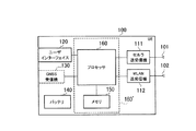
図2は、UE100のブロック図である。図2に示すように、UE100は、アンテナ101及び102と、セルラ送受信機111と、WLAN送受信機112と、ユーザインターフェイス120と、GNSS(Global Navigation Satellite System)受信機130と、バッテリ140と、メモリ150と、プロセッサ160と、を含む。メモリ150及びプロセッサ160は、制御部を構成する。UE100は、ユーザインターフェイス120及びGNSS受信機130を有していなくてもよい。また、メモリ150をプロセッサ160と一体化し、このセット(すなわち、チップセット)をプロセッサ160’としてもよい。
FIG. 2 is a block diagram of the
アンテナ101及びセルラ送受信機111は、セルラ無線信号の送受信に用いられる。セルラ送受信機111は、プロセッサ160が出力するベースバンド信号をセルラ無線信号に変換してアンテナ101から送信する。また、セルラ送受信機111は、アンテナ101が受信するセルラ無線信号をベースバンド信号に変換してプロセッサ160に出力する。
The
アンテナ102及びWLAN送受信機112は、WLAN無線信号の送受信に用いられる。WLAN送受信機112は、プロセッサ160が出力するベースバンド信号をWLAN無線信号に変換してアンテナ102から送信する。また、WLAN送受信機112は、アンテナ102が受信するWLAN無線信号をベースバンド信号に変換してプロセッサ160に出力する。
The
ユーザインターフェイス120は、UE100を所持するユーザとのインターフェイスであり、例えば、ディスプレイ、マイク、スピーカ、及び各種ボタン等を含む。ユーザインターフェイス120は、ユーザからの入力を受け付けて、該入力の内容を示す信号をプロセッサ160に出力する。GNSS受信機130は、UE100の地理的位置を示す位置情報を得るために、GNSS信号を受信して、受信した信号をプロセッサ160に出力する。バッテリ140は、UE100の各ブロックに供給すべき電力を蓄える。
The
メモリ150は、プロセッサ160によって実行されるプログラムと、プロセッサ160による処理に使用される情報と、を記憶する。プロセッサ160は、ベースバンド信号の変調・復調及び符号化・復号等を行うベースバンドプロセッサと、メモリ150に記憶されるプログラムを実行して各種の処理を行うCPUと、を含む。プロセッサ160は、さらに、音声・映像信号の符号化・復号を行うコーデックを含んでもよい。プロセッサ160は、後述する各種の処理及び各種の通信プロトコルを実行する。
The
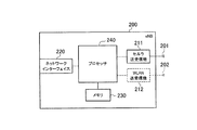
図3は、eNB200のブロック図である。図3に示すように、eNB200は、アンテナ201と、セルラ送受信機211と、ネットワークインターフェイス220と、メモリ230と、プロセッサ240と、を含む。メモリ230及びプロセッサ240は、制御部を構成する。また、メモリ230をプロセッサ240と一体化し、このセット(すなわち、チップセット)をプロセッサとしてもよい。
FIG. 3 is a block diagram of the
アンテナ201及びセルラ送受信機211は、セルラ無線信号の送受信に用いられる。セルラ送受信機211は、プロセッサ240が出力するベースバンド信号をセルラ無線信号に変換してアンテナ201から送信する。また、セルラ送受信機211は、アンテナ201が受信するセルラ無線信号をベースバンド信号に変換してプロセッサ240に出力する。
The
ネットワークインターフェイス220は、X2インターフェイスを介して隣接eNB200と接続され、S1インターフェイスを介してMME/S−GW500と接続される。ネットワークインターフェイス220は、直接的なインターフェイスを介してAP300と接続されていてもよい。
The
メモリ230は、プロセッサ240によって実行されるプログラムと、プロセッサ240による処理に使用される情報と、を記憶する。プロセッサ240は、ベースバンド信号の変調・復調及び符号化・復号等を行うベースバンドプロセッサと、メモリ230に記憶されるプログラムを実行して各種の処理を行うCPUと、を含む。プロセッサ240は、後述する各種の処理及び各種の通信プロトコルを実行する。
The
eNB200がセルラ・WLAN一体型である場合、eNB200は、アンテナ202と、WLAN送受信機212と、をさらに含む。アンテナ202及びWLAN送受信機212は、WLAN無線信号の送受信に用いられる。WLAN送受信機212は、プロセッサ240が出力するベースバンド信号をWLAN無線信号に変換してアンテナ202から送信する。また、WLAN送受信機212は、アンテナ202が受信するWLAN無線信号をベースバンド信号に変換してプロセッサ240に出力する。
When the
図4は、AP300のブロック図である。図4に示すように、AP300は、アンテナ301と、WLAN送受信機(WLAN通信部)311と、ネットワークインターフェイス320と、メモリ330と、プロセッサ340と、を有する。メモリ330をプロセッサ340と一体化し、このセット(すなわち、チップセット)をプロセッサとしてもよい。
FIG. 4 is a block diagram of the
アンテナ301及びWLAN送受信機311は、WLAN無線信号の送受信に用いられる。WLAN送受信機311は、プロセッサ340が出力するベースバンド信号をWLAN無線信号に変換してアンテナ301から送信する。また、WLAN送受信機311は、アンテナ301が受信するWLAN無線信号をベースバンド信号に変換してプロセッサ340に出力する。
The
ネットワークインターフェイス320は、直接的なインターフェイスを介してeNB200と接続される。
The
メモリ330は、プロセッサ340によって実行されるプログラムと、プロセッサ340による処理に使用される情報と、を記憶する。プロセッサ340は、ベースバンド信号の変調・復調及び符号化・復号等を行うベースバンドプロセッサと、メモリ330に記憶されるプログラムを実行して各種の処理を行うCPUと、を有する。プロセッサ340は、後述する各種の処理を実行する。
The
図5は、LTEシステムにおける無線インターフェイスのプロトコルスタック図である。図5に示すように、無線インターフェイスプロトコルは、OSI参照モデルの第1層乃至第3層に区分されており、第1層は物理(PHY)層である。第2層は、MAC(Medium Access Control)層、RLC(Radio Link Control)層、及びPDCP(Packet Data Convergence Protocol)層を含む。第3層は、RRC(Radio Resource Control)層を含む。 FIG. 5 is a protocol stack diagram of a radio interface in the LTE system. As shown in FIG. 5, the radio interface protocol is divided into the first to third layers of the OSI reference model, and the first layer is a physical (PHY) layer. The second layer includes a MAC (Medium Access Control) layer, an RLC (Radio Link Control) layer, and a PDCP (Packet Data Convergence Protocol) layer. The third layer includes an RRC (Radio Resource Control) layer.
物理層は、符号化・復号、変調・復調、アンテナマッピング・デマッピング、及びリソースマッピング・デマッピングを行う。UE100の物理層とeNB200の物理層との間では、物理チャネルを介してユーザデータ及び制御信号が伝送される。 The physical layer performs encoding / decoding, modulation / demodulation, antenna mapping / demapping, and resource mapping / demapping. Between the physical layer of UE100 and the physical layer of eNB200, user data and a control signal are transmitted via a physical channel.
MAC層は、データの優先制御、ハイブリッドARQ(HARQ)による再送処理等を行う。UE100のMAC層とeNB200のMAC層との間では、トランスポートチャネルを介してユーザデータ及び制御信号が伝送される。eNB200のMAC層は、上下リンクのトランスポートフォーマット(トランスポートブロックサイズ、変調・符号化方式)及びUE100への割当リソースブロックを決定するスケジューラを含む。
The MAC layer performs data priority control, retransmission processing by hybrid ARQ (HARQ), and the like. Between the MAC layer of the
RLC層は、MAC層及び物理層の機能を利用してデータを受信側のRLC層に伝送する。UE100のRLC層とeNB200のRLC層との間では、論理チャネルを介してユーザデータ及び制御信号が伝送される。
The RLC layer transmits data to the RLC layer on the receiving side using the functions of the MAC layer and the physical layer. Between the RLC layer of the
PDCP層は、ヘッダ圧縮・伸張、及び暗号化・復号化を行う。 The PDCP layer performs header compression / decompression and encryption / decryption.
RRC層は、制御信号を取り扱う制御プレーンでのみ定義される。UE100のRRC層とeNB200のRRC層との間では、各種設定のための制御信号(RRCメッセージ)が伝送される。RRC層は、無線ベアラの確立、再確立及び解放に応じて、論理チャネル、トランスポートチャネル、及び物理チャネルを制御する。UE100のRRCとeNB200のRRCとの間に接続(RRC接続)がある場合、UE100はRRCコネクティッド状態であり、そうでない場合、UE100はRRCアイドル状態である。
The RRC layer is defined only in the control plane that handles control signals. Control signals (RRC messages) for various settings are transmitted between the RRC layer of the
RRC層の上位に位置するNAS(Non−Access Stratum)層は、セッション管理及びモビリティ管理等を行う。MME300は、NASメッセージをUE100と送受信する。 A NAS (Non-Access Stratum) layer located above the RRC layer performs session management, mobility management, and the like. MME300 transmits / receives a NAS message with UE100.
また、LTEシステムでは、下りリンクにはOFDMA(Orthogonal Frequency Division Multiple Access)、上りリンクにはSC−FDMA(Single Carrier Frequency Division Multiple Access)がそれぞれ適用される。 Further, in the LTE system, OFDMA (Orthogonal Frequency Division Multiple Access) is applied to the downlink, and SC-FDMA (Single Carrier Frequency Multiple Access) is applied to the uplink.
無線フレームは、時間方向に並ぶ10個のサブフレームで構成される。各サブフレームは、時間方向に並ぶ2個のスロットで構成される。各サブフレームの長さは1msであり、各スロットの長さは0.5msである。各サブフレームは、周波数方向に複数個のリソースブロック(RB)を含み、時間方向に複数個のシンボルを含む。各リソースブロックは、周波数方向に複数個のサブキャリアを含む。UE100に割り当てられる無線リソース(時間・周波数リソース)のうち、周波数リソースはリソースブロックにより特定でき、時間リソースはサブフレーム(又はスロット)により特定できる。
The radio frame is composed of 10 subframes arranged in the time direction. Each subframe is composed of two slots arranged in the time direction. The length of each subframe is 1 ms, and the length of each slot is 0.5 ms. Each subframe includes a plurality of resource blocks (RB) in the frequency direction and includes a plurality of symbols in the time direction. Each resource block includes a plurality of subcarriers in the frequency direction. Among radio resources (time / frequency resources) allocated to the
(端末主導型の切り替え制御の基本動作)
3GPPのリリース12以降において、セルラ・WLAN無線インターワーキング技術がサポートされている(非特許文献1及び2参照)。このような技術では、RRCコネクティッド状態又はRRCアイドル状態のUE100は、E−UTRAN10とWLAN30との間で双方向のトラフィック切り替え(トラフィック・ステアリング)を行う。(Basic operation of terminal-driven switching control)
In
当該トラフィック切り替えは、E−UTRAN10の補助により、UE100主導(UE based)で行われる。また、当該トラフィック切り替えは、APN(Access Point Name)単位で行われる。以下において、このような切り替え制御を「UE主導型の切り替え制御」と称する。 The traffic switching is performed by the UE 100 (UE based) with the assistance of the E-UTRAN 10. The traffic switching is performed in units of APN (Access Point Name). Hereinafter, such switching control is referred to as “UE-driven switching control”.
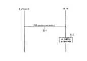
図6は、UE主導型の切り替え制御の基本動作を示す図である。 FIG. 6 is a diagram illustrating a basic operation of UE-driven switching control.
図6に示すように、ステップS11において、E−UTRAN10は、ブロードキャストRRCシグナリング又は個別(dedicated)RRCシグナリングにより、補助情報(RAN assistance parameters)をUE100に送信する。ブロードキャストRRCシグナリングは、例えばSIB(System Information Block)である。個別RRCシグナリングは、例えばRRC Connection Reconfigurationメッセージである。
As shown in FIG. 6, in step S11, the E-UTRAN 10 transmits auxiliary information (RAN assistance parameters) to the
補助情報は、E−UTRAN信号強度(受信電力)閾値及び品質閾値、WLANチャネル使用率閾値、WLANバックホールデータレート閾値、WLAN信号強度(受信電力)閾値及び品質閾値等を含む。補助情報は、UE主導型の切り替え制御の対象となるWLAN識別子を含んでもよい。WLAN識別子は、SSID、BSSID、HESSID等である。補助情報は、閾値(判定条件)が満たされるべき期間を指定するパラメータを含んでもよい。 The auxiliary information includes an E-UTRAN signal strength (received power) threshold and quality threshold, a WLAN channel usage rate threshold, a WLAN backhaul data rate threshold, a WLAN signal strength (received power) threshold, a quality threshold, and the like. The auxiliary information may include a WLAN identifier that is a target of UE-driven switching control. The WLAN identifier is SSID, BSSID, HESSID, or the like. The auxiliary information may include a parameter that specifies a period during which a threshold value (determination condition) should be satisfied.
UE主導型の切り替え制御をサポートするUE100は、補助情報を受信し、受信した補助情報を記憶する。UE100は、セル再選択又はハンドオーバを行う際に、記憶している補助情報を破棄してもよい。
The
ステップS12において、UE100は、UE主導型の切り替え制御を行う。
In step S12, the
先ず、セルラ通信からWLAN通信への切り替え、すなわち、E−UTRAN10からWLAN30への切り替えの一例について説明する。UE100は、セルラに関する第1の判定条件及びWLANに関する第2の判定条件に基づいて、セルラ通信からWLAN通信に切り替えるか否かの切り替え判定を行う。具体的には、第1の判定条件及び第2の判定条件の両方が満たされた場合、UE100は、セルラ通信からWLAN通信への切り替えを行う。
First, an example of switching from cellular communication to WLAN communication, that is, switching from E-UTRAN 10 to
第1の判定条件は、E−UTRANサービングセルに対する以下の条件である。 The first determination condition is the following condition for the E-UTRAN serving cell.
RSRPmeas < ThreshServingOffloadWLAN, LowP; or
RSRQmeas < ThreshServingOffloadWLAN, LowQ; RSRPmeas <Thresh ServingOffloadWLAN, LowP ; or
RSRQmeas <Thresh ServingOffloadWLAN, LowQ ;
ここで、「RSRPmeas」はUE100で測定するセルラ受信信号の受信電力、すなわち参照信号受信電力(RSRP)である。「RSRQmeas」はUE100で測定するセルラ受信信号の受信品質、すなわち参照信号受信品質(RSRQ)である。「ThreshServingOffloadWLAN, LowP」及び「ThreshServingOffloadWLAN, LowQ」は、補助情報に含まれており、WLAN30に切り替えるための閾値である。Here, “RSRPmeas” is the received power of the cellular received signal measured by the
第2の判定条件は、ターゲットWLANに対する以下の条件である。 The second determination condition is the following condition for the target WLAN.
ChannelUtilizationWLAN < ThreshChUtilWLAN, Low; and
BackhaulRateDlWLAN > ThreshBackhRateDLWLAN, High; and
BackhaulRateUlWLAN > ThreshBackhRateULWLAN, High; and
BeaconRSSI > ThreshBeaconRSSIWLAN, High; ChannelUtilizationWLAN <Thresh ChUtilWLAN, Low ; and
BackhaulRateDlWLAN> Thresh BackhRateDLWLAN, High ; and
BackhaulRateUlWLAN> Thresh BackhRateULWLAN, High ; and
BeaconRSSI> Thresh BeaconRSSIWLAN, High ;
ここで、「ChannelUtilizationWLAN」はWLANビーコン又はプローブ応答に含まれており、WLANチャネル使用率、すなわちWLAN無線負荷レベルを示す。「BackhaulRateDlWLAN」及び「BackhaulRateUlWLAN」は、ANQP(Access Network Query Protocol)により提供され、WLANバックホールの利用可能伝送レート、すなわちWLANバックホール負荷レベルを示す。「BeaconRSSIは、UE100で測定するビーコン信号の受信信号強度を示す。「ThreshChUtilWLAN, Low」、「ThreshBackhRateDLWLAN, High」、「ThreshBackhRateULWLAN, High」、「ThreshBeaconRSSIWLAN, High」は、補助情報に含まれており、WLAN30に切り替えるための閾値である。Here, “ChannelUtilization WLAN” is included in the WLAN beacon or probe response and indicates the WLAN channel usage rate, that is, the WLAN radio load level. “BackhaulRateDlWLAN” and “BackhaulRateUlWLAN” are provided by ANQP (Access Network Query Protocol) and indicate the available transmission rate of the WLAN backhaul, that is, the WLAN backhaul load level. “BeaconRSSI indicates the received signal strength of the beacon signal measured by UE 100. “ Thresh ChUtilWLAN, Low ”,“ Thresh BackhRateDLWLAN, High ”,“ Thresh BackhRateULWLAN, High ”,“ Thresh BeaconRSSIWLAN, High ”are included in the auxiliary information. It is a threshold value for switching to the
次に、WLAN通信からセルラ通信への切り替え、すなわち、WLAN30からE−UTRAN10への切り替えの一例について説明する。UE100は、セルラに関する第3の判定条件及びWLANに関する第4の判定条件に基づいて、WLAN通信からセルラ通信に切り替えるか否かの切り替え判定を行う。具体的には、第3の判定条件又は第4の判定条件の一方が満たされた場合、UE100は、WLAN通信からセルラ通信への切り替えを行う。
Next, an example of switching from WLAN communication to cellular communication, that is, switching from
第3の判定条件は、E−UTRANターゲットセルに対する以下の条件である。 The third determination condition is the following condition for the E-UTRAN target cell.
RSRPmeas > ThreshServingOffloadWLAN, HighP; and
RSRQmeas > ThreshServingOffloadWLAN, HighQ;RSRPmeas> Thresh ServingOffloadWLAN, HighP ; and
RSRQmeas> Thresh ServingOffloadWLAN, HighQ ;
ここで、「ThreshServingOffloadWLAN, HighP」及び「ThreshServingOffloadWLAN, HighQ」は、補助情報に含まれており、E−UTRAN10に切り替えるための閾値である。Here, “Thresh ServingOffloadWLAN, HighP ” and “Thresh ServingOffloadWLAN, HighQ ” are included in the auxiliary information and are threshold values for switching to E-UTRAN10.
第4の判定条件は、ソースWLANに対する以下の条件である。 The fourth determination condition is the following condition for the source WLAN.
ChannelUtilizationWLAN > ThreshChUtilWLAN, High; or
BackhaulRateDlWLAN < ThreshBackhRateDLWLAN, Low; or
BackhaulRateUlWLAN < ThreshBackhRateULWLAN, Low; or
BeaconRSSI < ThreshBeaconRSSIWLAN, Low;ChannelUtilizationWLAN> Thresh ChUtilWLAN, High ; or
BackhaulRateDlWLAN <Thresh BackhRateDLWLAN, Low ; or
BackhaulRateUlWLAN <Thresh BackhRateULWLAN, Low ; or
BeaconRSSI <Thresh BeaconRSSIWLAN, Low ;
ここで、「ThreshChUtilWLAN, High」、「ThreshBackhRateDLWLAN, Low」、「ThreshBackhRateULWLAN, Low」、「ThreshBeaconRSSIWLAN, Low」は、補助情報に含まれており、E−UTRAN10に切り替えるための閾値である。Here, “Thresh ChUtilWLAN, High ”, “Thresh BackhRateDLWLAN, Low ”, “Thresh BackhRateULWLAN, Low ”, and “Thresh BeaconRSSIWLAN, Low ” are included in the auxiliary information and are thresholds for switching to E-UTRAN10. .
(セルラ・WLANアグリゲーションの基本動作)
セルラ・WLAN無線インターワーキング技術を高度化するために、同一データベアラに属するトラフィックをセルラ通信及びWLAN通信を併用して送受信する技術(セルラ・WLANアグリゲーション)の提案がなされている(非特許文献3参照)。これにより、動的なセルラ・WLAN無線インターワーキングを可能とし、スループットの増大を図ることができる。このような技術では、セルラ・WLAN一体型(Collocated)のeNB200の使用が想定される。(Basic operation of cellular / WLAN aggregation)
In order to advance the cellular / WLAN wireless interworking technology, a technology for transmitting / receiving traffic belonging to the same data bearer using cellular communication and WLAN communication (cellular / WLAN aggregation) has been proposed (Non-Patent Document 3). reference). This enables dynamic cellular / WLAN wireless interworking and increases throughput. In such a technique, it is assumed that a cellular / WLAN integrated (Collocated)
図7は、セルラ・WLANアグリゲーションの基本動作を示す図である。図7において、送信側(Tx)は、UE100及びセルラ・WLAN一体型eNB200のうち一方である。受信側(Rx)は、UE100及びセルラ・WLAN一体型eNB200のうち他方である。
FIG. 7 is a diagram showing a basic operation of cellular / WLAN aggregation. In FIG. 7, the transmission side (Tx) is one of the
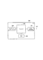
セルラ・WLANアグリゲーションにおいて、UE100は、セルラ通信のMAC層以下の第1のエンティティ410と、WLAN通信のMAC層以下の第2のエンティティ420と、セルラ通信のRLC層以上の第3のエンティティ430と、を含む。第3のエンティティ430は、RLC層及びPDCP層だけでなく、RRC層を含んでもよい。第2のエンティティ420と第3のエンティティ430との間には、WLAN MAC層とLTE RLC層との間でプロトコル変換を行う第4のエンティティ(WLAN RLC adaptation)440が設けられてもよい。
In the cellular / WLAN aggregation, the
同様に、セルラ・WLANアグリゲーションにおいて、セルラ・WLAN一体型eNB200は、セルラ通信のMAC層以下の第1のエンティティ410と、WLAN通信のMAC層以下の第2のエンティティ420と、セルラ通信のRLC層以上の第3のエンティティ430と、を含む。第3のエンティティ430は、RLC層及びPDCP層だけでなく、RRC層を含んでもよい。第2のエンティティ420と第3のエンティティ430との間には、WLAN MAC層とLTE RLC層との間でプロトコル変換を行う第4のエンティティ(WLAN RLC adaptation)440が設けられてもよい。
Similarly, in the cellular / WLAN aggregation, the cellular / WLAN integrated
次に、セルラ・WLAN一体型eNB200を送信側、UE100を受信側と仮定して、セルラ・WLANアグリゲーションの基本動作を説明する。但し、このような下りリンク動作に限らず、逆方向の動作(上りリンク動作)が行われてもよい。
Next, assuming that the cellular / WLAN integrated
図7に示すように、送信側であるセルラ・WLAN一体型eNB200において、第3のエンティティ430Tは、データベアラ(DRB:Data Radio Bearer)1に属するトラフィック(ユーザデータ)D1を処理する。そして、トラフィックD1の一部を第1のエンティティ410Tに提供し、トラフィックD1の残りを第2のエンティティ420Tに提供する。第1のエンティティ410Tは、第3のエンティティ430Tから提供されたトラフィックD2を処理し、トラフィックD2をセルラ通信により送信する。これに対し、第2のエンティティ420Tは、第3のエンティティ430Tから提供されたトラフィックD3を処理し、トラフィックD3をWLAN通信により送信する。
As shown in FIG. 7, in the cellular / WLAN-integrated
受信側であるUE100において、第1のエンティティ410Rは、セルラ通信によりトラフィックD2を受信し、トラフィックD2を処理して第3のエンティティ430Rに提供する。これに対し、第2のエンティティ420Rは、WLAN通信によりトラフィックD3を受信し、トラフィックD3を処理して第3のエンティティ430Rに提供する。第3のエンティティ430Rは、第1のエンティティ410Rから提供されたトラフィックD2及び第2のエンティティ420Rから提供されたトラフィックD3から、トラフィックD1を再構成し、トラフィックD1を処理して上位レイヤ(アプリケーション層等)に提供する。
In the
以下においては、eNB200のうちセルラ・WLAN一体型eNB200のみがセルラ・WLANアグリゲーションをサポートする一例を主として説明する。しかしながら、別ノードであるeNB200及びAP300を直接的なインターフェイスを介して接続し、eNB200及びAP300の組み合わせによりセルラ・WLANアグリゲーションをサポートしてもよい。
Hereinafter, an example in which only the cellular / WLAN-integrated
また、セルラ・WLANアグリゲーションの他の例については、その他の実施形態で説明する。 Other examples of cellular / WLAN aggregation will be described in other embodiments.
(動作環境)
図8は、第1実施形態に係る動作環境を示す図である。(Operating environment)
FIG. 8 is a diagram illustrating an operating environment according to the first embodiment.
図8に示すように、セルラ・WLAN一体型eNB200は、LTEカバレッジエリア及びWLANカバレッジエリアを形成する。LTEカバレッジエリアは、小セルに相当するカバレッジサイズである。小セルは、フェムトセルであってもよく、ピコセルであってもよい。LTEカバレッジエリアは、WLANカバレッジエリアよりも広い。
As shown in FIG. 8, the cellular / WLAN integrated
UE100は、WLANカバレッジエリア外、かつ、LTEカバレッジエリア内に位置している。UE100は、NB200のセルをサービングセルとして選択している。UE100は、上述したUE主導型の切り替え制御を行う。
The
ここで、セルラ通信からWLAN通信に切り替えるか否かの切り替え判定において、UE100は、第1の判定条件が満たされなければ、セルラ通信からWLAN通信への切り替えを行わない。第1の判定条件は、セルラ通信の無線状態が良好ではないことを示す。
Here, when determining whether to switch from cellular communication to WLAN communication, the
図8の破線で示す円の内側は、セルラ通信の無線状態が良好な領域、すなわち、第1の判定条件が満たされない領域である。WLANカバレッジエリアは図8の破線で示す円の内側に存在している。よって、WLANカバレッジエリアにおいて第1の判定条件が満たされることが困難であり、セルラ・WLAN一体型eNB200のWLANは殆ど使用されないことになる。そこで、第1実施形態では、以下の動作により、このような問題を解決する。
The inside of the circle indicated by the broken line in FIG. 8 is an area where the wireless state of cellular communication is good, that is, an area where the first determination condition is not satisfied. The WLAN coverage area exists inside a circle indicated by a broken line in FIG. Therefore, it is difficult to satisfy the first determination condition in the WLAN coverage area, and the WLAN of the cellular / WLAN integrated
(第1実施形態に係る動作)
UE100は、セルラネットワークから特定のWLAN識別子が指定されており、かつ、特定のWLAN識別子を含むWLAN受信信号を検出した場合、第1の判定条件に基づくことなく、第2の判定条件に基づいて切り替え判定を行う。第1実施形態では、特定のWLAN識別子は、セルラ・WLAN一体型eNB200に割り当てられているWLAN識別子である。(Operation according to the first embodiment)
When a specific WLAN identifier is designated from the cellular network and the
特定のWLAN識別子は、上述した補助情報(ブロードキャストRRCシグナリング又は個別RRCシグナリング)に含まれていてもよい。或いは、特定のWLAN識別子は、ANDSFサーバから提供されてもよい。 The specific WLAN identifier may be included in the above-described auxiliary information (broadcast RRC signaling or individual RRC signaling). Alternatively, the specific WLAN identifier may be provided from the ANDSF server.
以下においては、ブロードキャストRRCシグナリング又は個別RRCシグナリングにより特定のWLAN識別子を指定する一例を説明する。この場合、UE100は、ブロードキャストRRCシグナリングよりも個別RRCシグナリングを優先して適用することが好ましい。
In the following, an example in which a specific WLAN identifier is designated by broadcast RRC signaling or individual RRC signaling will be described. In this case, the
当該ブロードキャストRRCシグナリング又は個別RRCシグナリングは、セルラ・WLAN一体型eNB200により送信されてもよい。或いは、当該ブロードキャストRRCシグナリング又は個別RRCシグナリングは、セルラ・WLAN一体型eNB200と少なくとも一部が重複するセルを管理する他のeNB200により送信されてもよい。
The broadcast RRC signaling or dedicated RRC signaling may be transmitted by the cellular / WLAN integrated
図9は、特定のWLAN識別子の指定方法の第1の例を示す図である。図9に示すように、セルラネットワークは、特定のWLAN識別子のリストをUE100に提供する。第1実施形態では、当該リストは、セルラ・WLAN一体型eNB200に割り当てられているWLAN識別子のリストである。UE100は、ブロードキャストRRCシグナリング又は個別RRCシグナリングにより送信された特定のWLAN識別子を受信し、受信した特定のWLAN識別子を記憶する。
FIG. 9 is a diagram illustrating a first example of a specific WLAN identifier designation method. As shown in FIG. 9, the cellular network provides the
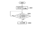
図10は、第1実施形態に係るUE100の動作を示す図である。ここでは、UE100が既に特定のWLAN識別子を記憶していると仮定する。
FIG. 10 is a diagram illustrating an operation of the
図10に示すように、ステップS101において、UE100は、WLAN信号を受信する。WLAN信号は、WLANビーコン又はプローブ応答等である。
As illustrated in FIG. 10, in step S101, the
ステップS102において、UE100は、WLAN受信信号に含まれるWLAN識別子が特定のWLAN識別子であるか否かを確認する。
In step S102, the
WLAN受信信号に含まれるWLAN識別子が特定のWLAN識別子でない場合、ステップS103において、UE100は、第1の判定条件及び第2の判定条件の両方に基づいて、セルラ通信からWLAN通信への切り替え判定を行う。
If the WLAN identifier included in the WLAN reception signal is not a specific WLAN identifier, in step S103, the
一方、WLAN受信信号に含まれるWLAN識別子が特定のWLAN識別子である場合、ステップS104において、UE100は、第1の判定条件に基づくことなく、第2の判定条件に基づいて、セルラ通信からWLAN通信への切り替え判定を行う。つまり、第1の判定条件を適用せずに切り替え判定を行う。
On the other hand, when the WLAN identifier included in the WLAN reception signal is a specific WLAN identifier, in step S104, the
このような動作を図8の動作環境を例に説明する。特定のWLAN識別子を記憶しているUE100がWLANカバレッジエリアに移動した場合を想定する。
Such an operation will be described by taking the operating environment of FIG. 8 as an example. Assume that the
UE100は、WLANカバレッジエリアにおいて、特定のWLAN識別子を含むWLAN無線信号を受信する。UE100は、当該特定のWLAN識別子を含むWLAN受信信号を検知し、セルラ通信からWLAN通信への切り替え判定を行う。UE100は、第1の判定条件に基づくことなく、第2の判定条件に基づいて切り替え判定を行う。これにより、セルラ・WLAN一体型eNB200のWLANが使用され易くなる。
The
図11は、特定のWLAN識別子の指定方法の第2の例を示す図である。 FIG. 11 is a diagram illustrating a second example of a method for designating a specific WLAN identifier.
図11に示すように、セルラネットワークは、WLAN識別子のリストと、当該WLAN識別子が特定のWLAN識別子であることを示すフラグと、をUE100に提供する。当該フラグは、例えば1ビットの情報(Collocation−Indicator)である。
As shown in FIG. 11, the cellular network provides the
[第1実施形態の変更例1]
図12は、第1実施形態の変更例1を示す図である。[First Modification of First Embodiment]
FIG. 12 is a diagram illustrating a first modification of the first embodiment.
図12に示すように、セルラネットワークは、セルラ・WLAN一体型eNB200に割り当てられているWLAN識別子をUE100に提供する際に、セルラ・WLAN一体型eNB200に割り当てられているセル識別子(特定のセル識別子)をUE100に提供する。セル識別子は、物理セル識別子(PCI)である。或いは、セル識別子は、EUTRANセル・グローバル識別子(ECGI)であってもよい。
As shown in FIG. 12, when the cellular network provides the
例えば、セルラ・WLAN一体型eNB200と少なくとも一部が重複するセルを管理する他のeNB200がブロードキャストRRCシグナリング又は個別RRCシグナリングにより特定のセル識別子を通知する。UE100は、セルラ・WLAN一体型eNB200に割り当てられている特定のセル識別子がセルラネットワークから通知されており、自UE100のWLAN通信機能がオフである場合、当該特定のセル識別子を含むセルラ受信信号を検出したことに応じて、WLAN通信機能をオンにする。
For example, another
このような動作を図8の動作環境を例に説明する。特定のセル識別子を記憶しているUE100が、LTEカバレッジエリアに移動した場合を想定する。UE100は、LTEカバレッジエリアにおいて、特定のセル識別子を含むセルラ無線信号を受信する。UE100は、当該特定のセル識別子を含むセルラ受信信号を検知し、自UE100のWLAN通信機能をオフからオンに切り替える。これにより、セルラ・WLAN一体型eNB200のWLANが使用され易くなる。
Such an operation will be described by taking the operating environment of FIG. 8 as an example. Assume that the
[第1実施形態の変更例2]
上述した第1実施形態では、特定のWLAN識別子として、セルラ・WLAN一体型eNB200に割り当てられているWLAN識別子を例示した。[Modification 2 of the first embodiment]
In the first embodiment described above, the WLAN identifier assigned to the cellular / WLAN-integrated
しかしながら、特定のWLAN識別子は、eNB200の近傍のAP300に割り当てられたWLAN識別子であってもよい。eNB200の近傍とは、例えば図8の破線で示す円の内側の範囲を指す。
However, the specific WLAN identifier may be a WLAN identifier assigned to the
本変更例によれば、eNB200の近傍のAP300が使用され易くなる。
According to this modified example, the
[第2実施形態]
次に、第2実施形態について説明する。第2実施形態に係るシステム構成、UE主導型の切り替え制御の基本動作、セルラ・WLANアグリゲーションの基本動作、及び動作環境は、第1実施形態と同様である。[Second Embodiment]
Next, a second embodiment will be described. The system configuration according to the second embodiment, the basic operation of UE-driven switching control, the basic operation of cellular / WLAN aggregation, and the operating environment are the same as those of the first embodiment.
以下において、第2実施形態に係る動作について、第1実施形態に係る動作との相違点を主として説明する。 In the following, the operation according to the second embodiment will be described mainly with respect to differences from the operation according to the first embodiment.
第2実施形態では、セルラネットワーク(eNB200又はANDSFサーバ)は、切り替え判定に使用される閾値をWLAN識別子ごとに指定する。例えば、eNB200は、ブロードキャストRRCシグナリング又は個別RRCシグナリングにより、複数のWLAN識別子と、当該複数のWLAN識別子のそれぞれに対応する閾値からなる複数の閾値と、を送信する。
In the second embodiment, the cellular network (
当該ブロードキャストRRCシグナリング又は個別RRCシグナリングは、セルラ・WLAN一体型eNB200により送信されてもよい。或いは、当該ブロードキャストRRCシグナリング又は個別RRCシグナリングは、セルラ・WLAN一体型eNB200と少なくとも一部が重複するセルを管理する他のeNB200により送信されてもよい。
The broadcast RRC signaling or dedicated RRC signaling may be transmitted by the cellular / WLAN integrated
UE100は、WLAN識別子ごとの閾値を受信し、WLAN識別子ごとの閾値を記憶する。UE100は、WLAN識別子ごとに閾値が指定されている場合、WLAN受信信号に含まれるWLAN識別子に対応する閾値を切り替え判定に使用する。
UE100 receives the threshold value for every WLAN identifier, and memorize | stores the threshold value for every WLAN identifier. When a threshold value is designated for each WLAN identifier, the
図13は、第2実施形態に係るUE100の動作を示す図である。ここでは、UE100がWLAN識別子ごとに閾値を記憶していると仮定する。また、閾値として、第1の判定条件における「ThreshServingOffloadWLAN, LowP」及び「ThreshServingOffloadWLAN, LowQ」を想定する。FIG. 13 is a diagram illustrating an operation of the
図13に示すように、ステップS201において、UE100は、WLAN信号を受信する。WLAN信号は、WLANビーコン又はプローブ応答等である。
As shown in FIG. 13, in step S201, the
ステップS202において、UE100は、WLAN識別子ごとに記憶している「ThreshServingOffloadWLAN, LowP」及び「ThreshServingOffloadWLAN, LowQ」の中から、WLAN受信信号に含まれるWLAN識別子に対応する「ThreshServingOffloadWLAN, LowP」及び「ThreshServingOffloadWLAN, LowQ」を選択する。In step S202,
ステップS203において、UE100は、第1の判定条件及び第2の判定条件に基づいて、セルラ通信からWLAN通信への切り替え判定を行う。ここで、第1の判定条件には、ステップS202で選択した「ThreshServingOffloadWLAN, LowP」及び「ThreshServingOffloadWLAN, LowQ」が使用される。In step S203, the
このような動作を図8の動作環境を例に説明する。セルラネットワークは、セルラ・WLAN一体型eNB200に割り当てられたWLAN識別子(特定のWLAN識別子)に対応する「ThreshServingOffloadWLAN, LowP」及び「ThreshServingOffloadWLAN, LowQ」を、他のWLAN識別子に比べて十分大きく設定する。これは、図8の破線で示す円が縮小することを意味するので、セルラ・WLAN一体型eNB200のWLANが使用され易くなる。Such an operation will be described by taking the operating environment of FIG. 8 as an example. Cellular network, set sufficiently larger than the cellular corresponding to the assigned WLAN identifier (specific WLAN identifier) to the WLAN integrated eNB200 "Thresh ServingOffloadWLAN, LowP" and "Thresh ServingOffloadWLAN, LowQ" and other WLAN identifier To do. This means that the circle indicated by the broken line in FIG. 8 is reduced, so that the WLAN of the cellular / WLAN integrated
また、当該特定のWLAN識別子に対応する「ThreshServingOffloadWLAN, LowP」をRSRP最大値に設定し、当該特定のWLAN識別子に対応する「ThreshServingOffloadWLAN, LowQ」をRSRQ最大値に設定することにより、UE100は、実質的に第1の判定条件を適用せずに、セルラ通信からWLAN通信への切り替え判定を行うことになる。これにより、セルラ・WLAN一体型eNB200のWLANが使用され易くなる。Also, by setting “Thresh ServingOffloadWLAN, LowP ” corresponding to the specific WLAN identifier to the RSRP maximum value, and setting “Thresh ServingOffloadWLAN, LowQ ” corresponding to the specific WLAN identifier to the RSRQ maximum value, the
[第2実施形態の変更例1]
上述した第2実施形態では、セルラネットワークは、切り替え判定に使用される閾値をWLAN識別子ごとに直接的に指定していた。しかしながら、セルラネットワークは、切り替え判定に使用される閾値をWLAN識別子ごとに間接的に指定してもよい。[
In the second embodiment described above, the cellular network directly designates the threshold used for switching determination for each WLAN identifier. However, the cellular network may indirectly specify a threshold value used for switching determination for each WLAN identifier.
本変更例では、セルラネットワークは、切り替え判定に使用される閾値に対するオフセット値を、WLAN識別子ごとに指定する。例えば、セルラ・WLAN一体型eNB200に割り当てられたWLAN識別子(特定のWLAN識別子)に対応する「ThreshServingOffloadWLAN, LowP」及び「ThreshServingOffloadWLAN, LowQ」を、他のWLAN識別子に比べて十分大きく設定(無限大(Infinity)に設定してもよい)するための正のオフセット値を指定する。In this modification, the cellular network designates an offset value for the threshold used for switching determination for each WLAN identifier. For example, “Thresh ServingOffloadWLAN, LowP ” and “Thresh ServingOffloadWLAN, LowQ ” corresponding to the WLAN identifier (specific WLAN identifier) assigned to the cellular / WLAN-integrated
UE100は、WLAN受信信号に含まれるWLAN識別子が特定のWLAN識別子である場合、特定のWLAN識別子に対応するオフセット値を適用して、「ThreshServingOffloadWLAN, LowP」及び「ThreshServingOffloadWLAN, LowQ」の値を大きく設定する。これは、図8の破線で示す円が縮小することを意味するので、セルラ・WLAN一体型eNB200のWLANが使用され易くなる。When the WLAN identifier included in the WLAN reception signal is a specific WLAN identifier , the UE 100 applies the offset value corresponding to the specific WLAN identifier, and sets the values of “Thresh ServingOffloadWLAN, LowP ” and “Thresh ServingOffloadWLAN, LowQ ”. Set larger. This means that the circle indicated by the broken line in FIG. 8 is reduced, so that the WLAN of the cellular / WLAN integrated
[第2実施形態の変更例2]
上述した第2実施形態及びその変更例1では、特定のWLAN識別子として、セルラ・WLAN一体型eNB200に割り当てられているWLAN識別子を例示した。[Second Modification of Second Embodiment]
In the above-described second embodiment and its modification example 1, the WLAN identifier assigned to the cellular / WLAN-integrated
しかしながら、特定のWLAN識別子は、eNB200の近傍のAP300に割り当てられたWLAN識別子であってもよい。本変更例によれば、eNB200の近傍のAP300が使用され易くなる。
However, the specific WLAN identifier may be a WLAN identifier assigned to the
[第3実施形態]
次に、第3実施形態について説明する。第3実施形態に係るシステム構成、UE主導型の切り替え制御の基本動作、セルラ・WLANアグリゲーションの基本動作、及び動作環境は、第1実施形態と同様である。[Third Embodiment]
Next, a third embodiment will be described. The system configuration according to the third embodiment, the basic operation of UE-driven switching control, the basic operation of cellular / WLAN aggregation, and the operating environment are the same as in the first embodiment.
以下において、第3実施形態に係る動作について、第1実施形態及び第2実施形態に係る動作との相違点を主として説明する。 In the following, the operation according to the third embodiment will be described mainly with respect to differences from the operations according to the first embodiment and the second embodiment.
上述したように、UE主導型の切り替え制御では、APN単位でトラフィック切り替えが行われる。これに対し、セルラ・WLANアグリゲーションでは、同一データベアラに属するトラフィックをセルラ通信及びWLAN通信を併用して送受信することが可能である。また、セルラ・WLANアグリゲーションの制御は、eNB200主導で行われることが想定される。よって、セルラ・WLANアグリゲーションをサポートするノードに対して、UE主導で全てのトラフィックを切り替えることは好ましくない。ここで、セルラ・WLANアグリゲーションをサポートするノードとは、セルラ・WLAN一体型eNB200、又はeNB200と直接的に接続されたAP300である。
As described above, in UE-driven switching control, traffic switching is performed on an APN basis. In contrast, in cellular / WLAN aggregation, traffic belonging to the same data bearer can be transmitted and received using both cellular communication and WLAN communication. Further, it is assumed that the cellular / WLAN aggregation control is performed by the
第3実施形態では、UE100は、セルラネットワーク(eNB200又はANDSFサーバ)から特定のWLAN識別子が指定されている場合、特定のWLAN識別子についてUE主導型の切り替え制御を無効とする。特定のWLAN識別子は、セルラ・WLANアグリゲーションをサポートするノードに割り当てられているWLAN識別子である。
In the third embodiment, when a specific WLAN identifier is specified from the cellular network (
例えば、eNB200は、ブロードキャストRRCシグナリング又は個別RRCシグナリングにより、特定のWLAN識別子のリストをUE100に送信する。特定のWLAN識別子の指定方法は、図9に示した方法を流用してもよいし、図11に示した方法を流用してもよい。また、個別RRCシグナリングは、WLAN測定を設定するためのWLAN測定指示であってもよい。この場合、特定のWLAN識別子は、WLAN測定指示に含まれる。
For example, the
図14は、第3実施形態に係るUE100の動作を示す図である。ここでは、UE100が既に特定のWLAN識別子を記憶していると仮定する。
FIG. 14 is a diagram illustrating an operation of the
図14に示すように、ステップS301において、UE100は、WLAN信号を受信する。WLAN信号は、WLANビーコン又はプローブ応答等である。
As shown in FIG. 14, in step S301, the
ステップS302において、UE100は、WLAN受信信号に含まれるWLAN識別子が特定のWLAN識別子であるか否かを確認する。
In step S302, the
WLAN受信信号に含まれるWLAN識別子が特定のWLAN識別子でない場合、ステップS303において、UE100は、UE主導型の切り替え制御を有効化し、セルラ通信からWLAN通信への切り替え判定を行う。
When the WLAN identifier included in the WLAN reception signal is not a specific WLAN identifier, in step S303, the
一方、WLAN受信信号に含まれるWLAN識別子が特定のWLAN識別子である場合、ステップS304において、UE100は、UE主導型の切り替え制御を無効化し、セルラ通信からWLAN通信への切り替え判定を行わない。
On the other hand, when the WLAN identifier included in the WLAN reception signal is a specific WLAN identifier, in step S304, the
[第4実施形態]
次に、第4実施形態について説明する。第4実施形態に係るシステム構成、UE主導型の切り替え制御の基本動作、セルラ・WLANアグリゲーションの基本動作、及び動作環境は、第1実施形態と同様である。[Fourth Embodiment]
Next, a fourth embodiment will be described. The system configuration according to the fourth embodiment, the basic operation of UE-driven switching control, the basic operation of cellular / WLAN aggregation, and the operating environment are the same as those of the first embodiment.
以下において、第4実施形態に係る動作について、第1実施形態乃至第3実施形態に係る動作との相違点を主として説明する。 In the following, the operation according to the fourth embodiment will be described mainly with respect to the differences from the operations according to the first to third embodiments.
上述した第3実施形態は、セルラ・WLANアグリゲーションが開始されていない場合を想定していた。しかしながら、セルラ・WLANアグリゲーションを実行中においても、UE主導型の切り替え制御が行われることは好ましくない。 The third embodiment described above assumes a case where cellular / WLAN aggregation is not started. However, it is not preferable that UE-driven switching control is performed even during the execution of cellular / WLAN aggregation.
そこで、第4実施形態では、UE100は、セルラ・WLANアグリゲーションを実行中である場合、UE主導型の切り替え制御を無効とする。例えば、UE100は、上述した補助情報を無視することにより、UE主導型の切り替え制御を無効とする。
Thus, in the fourth embodiment, the
図15は、第4実施形態に係るUE100の動作を示す図である。
FIG. 15 is a diagram illustrating an operation of the
図15に示すように、ステップS401において、UE100は、セルラ・WLANアグリゲーションを実行中であるか否かを確認する。
As shown in FIG. 15, in step S401, the
セルラ・WLANアグリゲーションを実行中でない場合、ステップS402において、UE100は、UE主導型の切り替え制御を有効化する。
When the cellular / WLAN aggregation is not being executed, the
一方、セルラ・WLANアグリゲーションを実行中である場合、ステップS403において、UE100は、UE主導型の切り替え制御を無効化する。
On the other hand, when the cellular / WLAN aggregation is being executed, in step S403, the
[第5実施形態]
次に、第5実施形態について説明する。第5実施形態に係るシステム構成、UE主導型の切り替え制御の基本動作、セルラ・WLANアグリゲーションの基本動作、及び動作環境は、第1実施形態と同様である。[Fifth Embodiment]
Next, a fifth embodiment will be described. The system configuration according to the fifth embodiment, the basic operation of UE-driven switching control, the basic operation of cellular / WLAN aggregation, and the operating environment are the same as those of the first embodiment.
以下において、第5実施形態に係る動作について、第1実施形態乃至第4実施形態に係る動作との相違点を主として説明する。 In the following, the operation according to the fifth embodiment will be described mainly with respect to differences from the operations according to the first to fourth embodiments.
図16は、第5実施形態に係る動作を示す図である。ここでは、セルラ・WLANアグリゲーションを実行中であると仮定する。 FIG. 16 is a diagram illustrating an operation according to the fifth embodiment. Here, it is assumed that cellular / WLAN aggregation is being executed.
図16に示すように、UE100は、セルラ通信のMAC層以下の第1のエンティティ410Aと、WLAN通信のMAC層以下の第2のエンティティ420Aと、セルラ通信のRLC層以上の第3のエンティティ430Aと、を含む。第3のエンティティ430Aは、RLC層及びPDCP層だけでなく、RRC層を含んでもよい。第2のエンティティ420Aと第3のエンティティ430Aとの間には、WLAN MAC層とLTE RLC層との間でプロトコル変換を行う第4のエンティティ(WLAN RLC adaptation)が設けられてもよい。
As shown in FIG. 16, the
セルラ・WLAN一体型eNB200は、セルラ通信のMAC層以下の第1のエンティティ410Bと、WLAN通信のMAC層以下の第2のエンティティ420Bと、セルラ通信のRLC層以上の第3のエンティティ430Bと、を含む。第3のエンティティ430Bは、RLC層及びPDCP層だけでなく、RRC層を含んでもよい。第2のエンティティ420Bと第3のエンティティ430Bとの間には、WLAN MAC層とLTE RLC層との間でプロトコル変換を行う第4のエンティティ(WLAN RLC adaptation)が設けられてもよい。
The cellular / WLAN integrated
上述したように、セルラカバレッジエリアは、WLANカバレッジエリアよりも広い。また、セルラ通信はライセンスドバンドで行われるため、アンライセンスドバンドで行われるWLAN通信に比べて安定した通信が可能である。 As described above, the cellular coverage area is wider than the WLAN coverage area. Further, since cellular communication is performed in the licensed band, stable communication is possible as compared with WLAN communication performed in the unlicensed band.
そこで、セルラ・WLANアグリゲーションにおいて、UE100の第3のエンティティ430Aは、第2のエンティティ420Aを介さずに、第1のエンティティ410Aを介して制御信号をeNB200と送受信する。また、eNB200の第3のエンティティ430Bは、第2のエンティティ420Bを介さずに、第1のエンティティ410Bを介して制御信号をUE100と送受信する。
Therefore, in the cellular / WLAN aggregation, the
このように、第3のエンティティ430が第1のエンティティ410Bを介して制御信号を送受信することにより、制御信号を安定的に送受信することができるため、セルラ・WLANアグリゲーションの信頼性を高めることができる。
As described above, since the third entity 430 can transmit and receive the control signal stably by transmitting and receiving the control signal via the
第3のエンティティ430が送受信する制御信号とは、RLC層の制御信号(例えば、ACK/NACK)である。或いは、第3のエンティティ430が送受信する制御信号とは、PDCP層の制御信号であってもよい。或いは、第3のエンティティ430が送受信する制御信号とは、RRC層の制御信号であってもよい。 The control signal transmitted / received by the third entity 430 is an RLC layer control signal (for example, ACK / NACK). Alternatively, the control signal transmitted and received by the third entity 430 may be a PDCP layer control signal. Alternatively, the control signal transmitted and received by the third entity 430 may be an RRC layer control signal.
[第6実施形態]
次に、第6実施形態について説明する。第6実施形態に係るシステム構成、UE主導型の切り替え制御の基本動作、セルラ・WLANアグリゲーションの基本動作、及び動作環境は、第1実施形態と同様である。[Sixth Embodiment]
Next, a sixth embodiment will be described. The system configuration according to the sixth embodiment, the basic operation of UE-driven switching control, the basic operation of cellular / WLAN aggregation, and the operating environment are the same as in the first embodiment.
以下において、第6実施形態に係る動作について、第1実施形態乃至第5実施形態に係る動作との相違点を主として説明する。 In the following, the operation according to the sixth embodiment will be described mainly with respect to differences from the operations according to the first to fifth embodiments.
上述したように、セルラ・WLANアグリゲーションは、動的なセルラ・WLAN無線インターワーキングを可能としようとする技術である。よって、セルラ・WLANアグリゲーションにおけるセルラ・WLANリソース割り振りの比率を決定する方法を確立することが好ましい。 As described above, the cellular / WLAN aggregation is a technique that enables dynamic cellular / WLAN wireless interworking. Therefore, it is preferable to establish a method for determining the ratio of cellular / WLAN resource allocation in cellular / WLAN aggregation.
図17は、第6実施形態に係るeNB200の動作を示す図である。ここでは、eNB200がセルラ・WLAN一体型eNB200である場合を想定する。
FIG. 17 is a diagram illustrating an operation of the
図17に示すように、ステップS601において、eNB200は、セルラ・WLANアグリゲーションを実行する際に、UE100の未送信データ量を示すバッファ状態報告をUE100から受信する。
As illustrated in FIG. 17, in step S601, the
ステップS602において、eNB200は、バッファ状態報告に基づいて、セルラ通信の上りリンクにおいてUE100に割り当てる無線リソースとWLAN通信の上りリンクにおいてUE100に割り当てる無線リソースとの比率を決定する。
In step S602, based on the buffer status report, the
セルラ・WLANアグリゲーションを実行中において、バッファ状態報告は、UE100の第3のエンティティ430Aにより生成されることが好ましい。すなわち、UE100は、RLC層又はPDCP層における未送信データ量をバッファ状態報告によりeNB200に通知する。バッファ状態報告はMAC層、物理層の未送信データ量を含んでもよい。これにより、eNB200は、UE100の全体的な未送信データ量を把握して、セルラ・WLANリソース割り振りの比率を適切に決定できる。
While performing cellular WLAN aggregation, the buffer status report is preferably generated by the
或いは、セルラ通信を開始した後、セルラ・WLANアグリゲーションを開始する場合、バッファ状態報告は、UE100の第1のエンティティ410Aにより生成されたものであってもよい。これにより、eNB200は、セルラ・WLANアグリゲーションを開始する際のセルラ・WLANリソース割り振りの比率を決定できる。
Alternatively, when cellular WLAN aggregation is started after starting cellular communication, the buffer status report may be generated by the
eNB200は、セルラ・WLANリソース割り振りの比率を決定した場合、セルラ・WLANアグリゲーションを実行中のUE100(セルラ・WLANアグリゲーションを開始するUE100)に対して、セルラ通信によるUE100の送信データ量とWLAN通信によるUE100の送信データ量との比率である上り送信比率を設定する制御情報を送信することができる。例えば、eNB200は、制御情報を含むRRC Connection ReconfigurationメッセージをUE100に送信してもよい。或いは、eNB200は、DCI、MAC CE、RLC Control PDU、及びPDCP Control PDUの少なくともいずれかによって、制御情報をUE100に送信(通知)してもよい。
When the
UE100は、制御情報に基づいて、上り送信比率を設定する。UE100は、設定された上り送信比率に基づいて、上りリンクにおける送信データをセルラ通信及びWLAN通信を併用して送信する。
The
なお、eNB200がセルラ・WLAN一体型eNB200でない場合、セルラ・WLANアグリゲーションの対象となるAP300がセルラ・WLANリソース割り振りの比率(又は上り送信比率)を決定して、決定された比率をeNB200に送信してもよい。
If the
また、eNB200がセルラ・WLAN一体型eNB200である場合、WLAN通信におけるスループットを推定可能な情報に基づいて、上り送信比率を決定してもよい。eNB200がセルラ・WLAN一体型eNB200でない場合、eNB200は、セルラ・WLANアグリゲーションを実行するAP300のスループットを推定可能な情報をAP300から取得し、当該取得した情報に基づいて、上り送信比率を決定してもよい。
Moreover, when eNB200 is cellular and WLAN integrated eNB200, you may determine an uplink transmission ratio based on the information which can estimate the throughput in WLAN communication. When the
スループットを推定可能な情報は、例えば、AP300に接続しているUEの数(eNB200がセルラ・WLAN一体型eNB200である場合、WLAN通信を行っているUEの数)、WLAN通信におけるチャネル利用率(WLAN channel utilization)、WLAN通信において利用可能な下り周波数帯(WLAN DLBandwidth)、及び、WLAN通信において利用可能な上り周波数帯(WLAN ULBandwidth)の少なくともいずれかである。
Information for which throughput can be estimated includes, for example, the number of UEs connected to the AP 300 (if the
なお、スループットを推定可能な情報は、上り送信比率だけでなく、下りリンクにおけるセルラ通信によるUE100への送信データ量(eNB200の送信データ量)とWLAN通信によるUE100への送信データ量(AP300の送信データ量)との比率である下り送信比率を決定するために用いられてもよい。
Note that the information whose throughput can be estimated includes not only the uplink transmission ratio but also the amount of data transmitted to the
eNB200は、下りリンクにおいてのみセルラ・WLANアグリゲーションを実行すると決定してもよい。この場合、上り送信比率は、100(セルラ通信)対0(WLAN通信)である。なお、下り送信比率を、0(セルラ通信)対100(WLAN通信)としてもよい。
The
また、eNB200は、WLAN通信における無線リンク障害が発生した場合、WLAN通信の利用率を設定値よりも低減させることができる。ここで、WLAN通信の利用率は、セルラ通信及びWLAN通信の上り(下り)送信比率に対するWLAN通信の上り(下り)送信比率(=(WLAN通信の上り(下り)送信比率)/(セルラ通信及びWLAN通信の上り(下り)送信比率))である。 Moreover, eNB200 can reduce the utilization rate of WLAN communication from a setting value, when the radio link failure in WLAN communication generate | occur | produces. Here, the utilization rate of WLAN communication is the uplink (downlink) transmission ratio of WLAN communication to the uplink (downlink) transmission ratio of cellular communication and WLAN communication (= (uplink (downlink) transmission ratio of WLAN communication) / (cellular communication and WLAN communication uplink (downlink) transmission ratio)).
eNB200は、例えば、上り送信比率及び下り送信比率を100(セルラ通信)対0(WLAN通信)に設定してもよい。この場合、eNB200は、当該設定値を示す制御情報を明示的にUE100に送信してもよい。この設定値は、例えば、上り送信比率、下り送信比率、WLAN通信の利用率などである。
For example, the
或いは、UE100は、WLAN通信の利用率が閾値よりも低減するように(例えば、100(セルラ通信)対0(WLAN通信)になるように)、上り送信比率及び下り送信比率を自律的に設定してもよい。例えば、UE100は、WLAN通信における無線リンク障害を検知して、eNB200に無線リンク障害報告を送信した場合、eNB200は、UE100が上り送信比率及び下り送信比率を自律的に設定したと判定してもよい。
Alternatively, the
なお、eNB200は、WLAN通信における無線リンク障害が発生した場合、WLAN通信における送信データ量を減らしてもよい。これにより、セルラ通信における送信データ量が増えるため、結果的に、WLAN通信の利用率が低減する。
Note that the
WLAN通信における無線リンク障害が解消した場合、UE100は、WLAN通信における無線リンク障害が発生する前の設定値に上り送信比率及び下り送信比率を自律的に戻してもよい。或いは、UE100は、WLAN通信における無線リンク障害が解消した後に、eNB200から受信した制御情報に基づいて、上り送信比率及び下り送信比率を新たに設定してもよい。
When the radio link failure in the WLAN communication is resolved, the
或いは、UE100は、eNB200から受信した制御情報に基づいて上り送信比率を設定する第1モードと、上り送信比率を自律的に設定する第2モードとを切り替え可能であってもよい。例えば、eNB200は、第1モードと第2モードとの切り替えに関する制御情報をUE100に送信してもよい。この制御情報は、第1モード又は第2モードに切り替えるためのフラグ情報であってもよい。例えば、第1モードを示すフラグがONである制御情報を受信したUE100は、第1モードに切り替え、第1モードを示すフラグがOFFである制御情報を受信したUE100は、第2モードに切り替える。或いは、制御情報は、第1モードと第2モードとを切り替えるためのトリガを示す情報であってもよい。例えば、UE100は、AP300から受信した負荷情報によって示される負荷(例えば、WLANチャネル使用率、WLANバックホールの利用可能伝送レート)が閾値以上である場合、第1モードに切り替え、AP300から受信した負荷情報によって示される負荷が閾値未満である場合、第2モードに切り替える。
Alternatively, the
[第6実施形態の変更例1]
次に、第6実施形態の変更例1について、図18から図20を用いて説明する。図18は、第6実施形態の変更例1に係るUE100が有するバッファを説明するための図(その1)である。図19は、第6実施形態の変更例1に係るUE100が有するバッファを説明するための図(その2)である。図20は、第6実施形態の変更例1に係るUE100が有するバッファを説明するための図(その3)である。以下において、第6実施形態と異なる部分を中心に説明し、同様の部分は説明を適宜省略する。第6実施形態の変更例1では、UE100がeNB200に送信するバッファ状態報告について詳細に説明する。[
Next,
本変更例において、セルラ・WLANアグリゲーションを実行するUE100は、以下に示すいずれかの形態のバッファを有する。
In this modification, the
(A)第1のバッファ形態
図18に示すように、セルラ・WLANアグリゲーションを実行中のUE100は、セルラ通信における未送信データを記憶する第1のRLC PDUバッファ(PDU buffer for licensed spectrum)610cと、WLAN通信における未送信データを記憶する第2のRLC PDUバッファ(PDU buffer for unlicensed spectrum)610wとを有する。具体的には、第1のRLC PDUバッファ610cは、RLC層610によって処理が行われ、且つセルラ通信におけるMAC層への送信待ちのデータユニットを記憶する。第2のRLC PDUバッファ610wは、RLC層610によって処理が行われ、且つWLAN通信におけるMAC層への送信待ちのデータユニットを記憶する。(A) First Buffer Form As shown in FIG. 18, the
第1のバッファ形態では、WLAN通信における未送信データは、送信用のデータとしてeNB200に直接的に報告されないケースである。
In the first buffer mode, untransmitted data in WLAN communication is not directly reported to
UE100は、セルラ・WLANアグリゲーションを実行中に、第1のRLC PDUバッファ610c及び第2のRLC PDUバッファ610wに基づいて、未送信データ量を示すバッファ状態報告(BSR)をeNB200に送信できる。具体的には、UE100は、以下の第1から第3の方法のいずれかに基づいて、バッファ状態報告によって示される未送信データ量を算出する。
The
第1に、UE100は、セルラ通信における未送信データ量のみを未送信データ量として算出する。従って、UE100は、当該未送信データ量を示すバッファ状態報告をeNB200に送信できる。この場合において、バッファ状態報告が示す未送信データ量は、例えば、第1のRLC PDUバッファ610cに記憶された未送信データ量そのものである。
First, the
第2に、UE100は、セルラ通信及びWLAN通信の上りリンクにおける送信データ量に対するセルラ通信の上りリンクにおける送信データ量の比率(分割比率)に応じて補正されたセルラ通信における未送信データ量を算出する。
Second, the
ここで、RLC SDUバッファ610s、PDCP PDUバッファ620p及びPDCP SDUバッファ620sは、セルラ通信及びWLAN通信における未送信データが記憶されている。このため、UE100は、これらの未送信データ量を示す通常のバッファ状態報告をeNB200に送信しても、eNB200は、セルラ通信における未送信データ量が把握できない。
Here, the
従って、UE100は、分割比率に応じて補正されたセルラ通信における未送信データ量を示すバッファ状態報告をeNB200に送信できる。これによって、eNB200は、セルラ通信における未送信データ量を把握できる。
Therefore, the
例えば、UE100は、RLC SDUバッファ610sに記憶された未送信データを分割比率に応じて補正する。UE100は、補正された未送信データをセルラ通信における未送信データ量として、eNB200に報告する。なお、UE100は、PDCP PDUバッファ620p(又はPDCP SDUバッファ620s)に記憶された未送信データ量を分割比率に応じて補正し、補正された未送信データ量を示すバッファ状態報告をeNB200に送信してもよい。
For example, the
なお、RLC SDUバッファ610sは、PDCP層620によって処理が行われ、且つRLC層610における処理待ちのデータユニットを記憶する。PDCP PDUバッファ620pは、PDCP層620によって処理が行われ、且つRLC層610への送信待ちのデータユニットを記憶する。PDCP SDUバッファ620sは、PDCP層620における処理待ちのデータユニットを記憶する。
Note that the
第3に、UE100は、セルラ通信における未送信データ量にWLAN通信における未送信データ量を加えて、未送信データ量を算出する。従って、UE100は、セルラ通信における未送信データ量及びWLAN通信における未送信データ量を示すバッファ状態報告をeNB200に送信できる。具体的には、バッファ状態報告によって示される未送信データ量は、第1のRLC PDUバッファ610cと第2のRLC PDUバッファ610wとに記憶された未送信データ量の合計値である。
Thirdly, the
これにより、バッファ状態報告によって示される未送信データ量は、セルラ通信における未送信データ量だけでなく、WLAN通信における未送信データ量が考慮されている。従って、eNB200は、バッファ状態報告に基づいて、セルラ・WLANリソース割り振りの比率を適切に決定できる。
Thus, the amount of untransmitted data indicated by the buffer status report takes into account not only the amount of untransmitted data in cellular communication but also the amount of untransmitted data in WLAN communication. Therefore, the
なお、第1のバッファ形態では、eNB200は、RLC層において、セルラ通信によりUE100から送信されたデータユニットと、WLAN通信によりUE100から送信されたデータユニットとを結合する。
In the first buffer mode,
(B)第2のバッファ形態
図19に示すように、セルラ・WLANアグリゲーションを実行中のUE100は、セルラ通信における未送信データを記憶する第1のPDCP PDUバッファ(PDU buffer for licensed spectrum)620cと、WLAN通信における未送信データを記憶する第2のPDCP PDUバッファ(PDU buffer for unlicensed spectrum)620wとを有する。具体的には、第1のPDCP PDUバッファ620cは、PDCP層620によって処理が行われ、且つセルラ通信におけるRLC層への送信待ちのデータユニットを記憶する。第2のPDCP PDUバッファ610wは、PDCP層620によって処理が行われ、且つWLAN通信におけるMAC層への送信待ちのデータユニットを記憶する。(B) Second Buffer Form As shown in FIG. 19, the
UE100は、セルラ・WLANアグリゲーションを実行中に、第1のPDCP PDUバッファ620c及び第2のPDCP PDUバッファ620wに基づいて、未送信データ量を示すバッファ状態報告をeNB200に送信できる。具体的には、UE100は、以下の第1から第3の方法のいずれかに基づいて、バッファ状態報告によって示される未送信データ量を算出する。なお、上述の第1のバッファ形態と同様の部分は、説明を適宜省略する。
The
第1に、UE100は、セルラ通信における未送信データ量のみを未送信データ量として算出する。従って、UE100は、当該未送信データ量を示すバッファ状態報告をeNB200に送信できる。この場合において、バッファ状態報告が示す未送信データ量は、例えば、第1のPDCP PDUバッファ620cに記憶された未送信データ量そのものである。
First, the
第2に、UE100は、分割比率に応じて補正されたセルラ通信における未送信データ量を算出する。
Secondly, the
例えば、UE100は、PDCP SDUバッファ620ssに記憶された未送信データを分割比率に応じて補正する。UE100は、補正された未送信データをセルラ通信における未送信データ量として、eNB200に報告することができる。
For example, the
第3に、UE100は、セルラ通信における未送信データ量にWLAN通信における未送信データ量を加えて、未送信データ量を算出する。具体的には、バッファ状態報告によって示される未送信データ量は、第1のPDCP PDUバッファ620cと第2のPDCP PDUバッファ620wとに記憶された未送信データ量の合計値である。
Thirdly, the
なお、PDCP層620において、第2のPDCP PDUバッファ620wに記憶されるデータユニット(パケット)は、トラフィックタイプに応じて、以下の4つのアクセスカテゴリ(AC:AC_VO/AC_VI/AC_BE/AC_BK)に分類されてもよい。PDCP層620は、分類したアクセスカテゴリの種別をWLAN通信側のMAC層(MAC for unlicensed spectrum)に通知してもよい。
In the
・AC_VO(優先度1):Voice
・AC_VI(優先度2):Video
・AC_BE(優先度3):Best Effort
・AC_BK(優先度4):Back GroundAC_VO (priority level 1): Voice
AC_VI (priority level 2): Video
AC_BE (priority level 3): Best Effort
AC_BK (priority level 4): Back Ground
なお、第2のバッファ形態では、eNB200は、PDCP層において、セルラ通信によりUE100から送信されたデータユニットと、WLAN通信によりUE100から送信されたデータユニットとを結合する。
In the second buffer mode,
(C)第3のバッファ形態
図20に示すように、セルラ・WLANアグリゲーションを実行中のUE100は、第1のRLC PDUバッファ610cと、第2のRLC PDUバッファ610wと、第1のPDCP PDUバッファ620cと、第2のPDCP PDUバッファ620wと、を有する。さらに、UE100は、WLAN通信における未送信データを記憶するWLAN入力バッファ630を有する。WLAN入力バッファ630は、WLAN通信におけるMAC層への処理待ちのデータユニットを記憶する。第2のRLC PDUバッファ610w内のデータユニット及び第2のPDCP PDUバッファ620w内のデータユニットが、WLAN入力バッファ630に入力される。(C) Third Buffer Configuration As shown in FIG. 20, the
第3のバッファ形態では、WLAN通信における未送信データは、送信用のデータとしてeNB200に直接的に報告できるケースである。
In the third buffer mode, untransmitted data in WLAN communication can be directly reported to
従って、UE100は、セルラ通信における未送信データ量とWLAN通信における未送信データ量とのそれぞれを、未送信データ量として算出する。例えば、WLAN通信における未送信データ量は、第2のRLC PDUバッファ610w、第2のPDCP PDUバッファ620w及びWLAN入力バッファ630のうち、少なくともいずれか1つにおける未送信データ量であってもよいし、第2のRLC PDUバッファ610w及び第2のPDCP PDUバッファ620wの合計値であってもよい。
Therefore, the
なお、第3のバッファ形態では、eNB200は、RLC層又はPDCP層において、セルラ通信によりUE100から送信されたデータユニットと、WLAN通信によりUE100から送信されたデータユニットとを結合する。
Note that, in the third buffer mode, the
なお、セルラ・WLANアグリゲーション用のデータベアラがRLC層において分割されている場合、UE100は、第1のRLC PDUバッファ610cと、第2のRLC PDUバッファ610wと、通常のRLC PDUバッファを有し、第1のPDCP PDUバッファ620cと、第2のPDCP PDUバッファ620wとを有さなくてもよい。また、セルラ・WLANアグリゲーション用のデータベアラがPDCP層において分割されている場合、UE100は、第1のPDCP PDUバッファ620cと、第2のPDCP PDUバッファ620wと、通常のPDCP PDUバッファを有し、第1のRLC PDUバッファ610cと、第2のRLC PDUバッファ610wとを有さなくてもよい。
When the data bearer for cellular / WLAN aggregation is divided in the RLC layer, the
[第6実施形態の変更例2]
次に、第6実施形態の変更例2について説明する。第6実施形態の変更例2では、UE100が上り送信比率を決定する一例を説明する。[Modification 2 of the sixth embodiment]
Next, Modification 2 of the sixth embodiment will be described. In the second modification of the sixth embodiment, an example in which the
UE100は、セルラ・WLANアグリゲーションを実行中に、セルラ通信の下りリンクにおいて受信に成功したデータユニットの数とWLAN通信の下りリンクにおいて受信に成功したデータユニットの数とに基づいて、セルラ通信の上りリンクにおける送信データ量とWLAN通信の上りリンクにおける送信データ量との比率を決定できる。なお、受信に成功したデータユニットとは、UE100において正しくデコードされたデータユニットである。
While performing cellular / WLAN aggregation, the
例えば、eNB200が、下り送信比率を、70(セルラ通信)対30(WLAN通信)に設定し、eNB200及びAP300がセルラ・WLANアグリゲーションによりUE100にデータを送信したと仮定する。一方、UE100は、セルラ通信において受信に成功したデータユニットの数(セルラデータユニット数)が30であり、WLAN通信において受信に成功したデータユニットの数(WLANデータユニット数)が30であったと仮定する。UE100は、受信したデータユニットの数(セルラデータユニット数及びWLANデータユニット数)に基づいて、上り送信比率を50(30)対50(30)に決定する。その後、UE100は、決定した上り送信比率に応じてデータを送信する。
For example, it is assumed that the
なお、受信に成功したデータユニットの数は、単位時間当たりに受信に成功したデータユニットの数であってもよい。eNB200は、この単位時間(例えば30s)の情報をUE100に通知し、UE100は、単位時間当たりに受信に成功したデータユニットの数をカウントする。例えば、UE100は、過去30sの間に受信に成功したデータユニットの数をカウントする。また、上り送信比率は、所定期間において受信したデータユニットの数の平均値(例えば、移動平均)に基づいて、決定されてもよい。eNB200は、この平均値に基づいて上り送信比率を決定するための情報をUE100に通知してもよい。
Note that the number of data units successfully received may be the number of data units successfully received per unit time. The
或いは、UE100は、「(WLAN通信の受信データ割合)+α(係数)>(前回のWLAN通信の上り送信データ割合)」を満たす場合に、次回のWLAN通信の上り送信データ割合が前回のWLAN通信の上り送信データ割合よりも大きくなるように、上り送信比率を決定し、上記式を満たさない場合に、次回のWLAN通信の上り送信データ割合が前回のWLAN通信の上り送信データ割合よりも小さくなるように、上り送信比率を決定してもよい。なお、eNB200は、α(係数)を示す情報をUE100に通知してもよい。
Alternatively, when the
なお、WLAN通信の受信データ割合 = (WLANデータユニット数)/(セルラデータユニット数+WLANデータユニット数)である。WLAN通信の上り送信データ割合 = (WLAN通信による上り送信データ量)/(セルラ通信による上り送信データ量+WLAN通信による上り送信データ量)である。 Note that the ratio of received data of WLAN communication = (number of WLAN data units) / (number of cellular data units + number of WLAN data units). The ratio of uplink transmission data of WLAN communication = (uplink transmission data amount by WLAN communication) / (uplink transmission data amount by cellular communication + uplink transmission data amount by WLAN communication).
UE100は、eNB200が決定した(下り)送信比率を考慮できると共に、無線状況を考慮できるため、効率的に上り送信比率を決定できる。さらに、eNB200からの上り送信比率に関する制御情報が不要となるため、シグナリングを低減できる。
Since the
また、eNB200は、セルラ通信によって受信に成功したUE100からのデータユニットの数と(セルラデータユニット数)WLAN通信によって受信に成功したUE100からのデータユニットの数(WLANデータユニット数)とに基づいて、セルラ通信によるUE100への送信データ量とWLAN通信によるUE100への送信データ量との下り送信比率を決定してもよい。eNB200は、例えば、セルラ通信によって受信に成功したデータユニットの数が30であり、WLAN通信によってAP300を経由して受信に成功したデータユニットの数が30である場合、下り送信比率を50(30)対50(30)に決定する。
Further, the
或いは、eNB200は、「(WLAN通信の受信データ割合)+α(係数)>(前回のWLAN通信の下り送信データ割合)」を満たす場合に、次回のWLAN通信の下り送信データ割合が前回のWLAN通信の下り送信データ割合よりも大きくなるように、下り送信比率を決定し、上記式を満たさない場合に、次回のWLAN通信の下り送信データ割合が前回のWLAN通信の下り送信データ割合よりも小さくなるように、下り送信比率を決定してもよい。
Alternatively, when
なお、「WLAN通信の受信データ割合 = (WLANデータユニット数)/(セルラデータユニット数+WLANデータユニット数)」である。「WLAN通信の下り送信データ割合 = (WLAN通信による下り送信データ量)/(セルラ通信による下り送信データ量+WLAN通信による下り送信データ量)」である。 Note that “WLAN communication received data ratio = (number of WLAN data units) / (number of cellular data units + number of WLAN data units)”. “Downlink transmission data ratio of WLAN communication = (Downlink transmission data amount by WLAN communication) / (Downlink transmission data amount by cellular communication + Downlink transmission data amount by WLAN communication)”.
eNB200は、無線状況を考慮して、効率的に上り送信比率を決定できる。
The
なお、eNB200は、上述した第6実施形態と同様に、第1モードと第2モード(セルラデータユニット数とWLANデータユニット数とに基づいて、上り送信比率を自律的に設定(決定)するモード)との切り替えに関する制御情報をUE100に送信してもよい。
In addition, eNB200 is the mode which autonomously sets (determines) an uplink transmission ratio based on 1st mode and 2nd mode (the number of cellular data units and the number of WLAN data units) similarly to 6th Embodiment mentioned above. ) May be transmitted to the
[第7実施形態]
次に、第7実施形態について説明する。第7実施形態に係るシステム構成、UE主導型の切り替え制御の基本動作、セルラ・WLANアグリゲーションの基本動作、及び動作環境は、第1実施形態と同様である。[Seventh Embodiment]
Next, a seventh embodiment will be described. The system configuration according to the seventh embodiment, the basic operation of UE-driven switching control, the basic operation of cellular / WLAN aggregation, and the operating environment are the same as in the first embodiment.
以下において、第7実施形態に係る動作について、第1実施形態乃至第6実施形態に係る動作との相違点を主として説明する。 In the following, the operation according to the seventh embodiment will be described mainly with respect to differences from the operations according to the first to sixth embodiments.
第7実施形態は、WLAN通信を選択しているUE100がセルラ・WLANアグリゲーションを開始するための方法に関する。WLAN通信を選択しているUE100がセルラ・WLANアグリゲーションを開始するために、UE100は、セルラ通信の接続をeNB200と確立する必要がある。セルラ・WLANアグリゲーションをサポートするノードのWLAN識別子がUE100に通知されている場合、UE100は、WLAN通信の接続先ノードがセルラ・WLANアグリゲーションをサポートすることを確認した上で、セルラ通信の接続をeNB200と確立することが好ましい。
7th Embodiment is related with the method for UE100 which has selected WLAN communication to start cellular and WLAN aggregation. In order for the
或いは、UE100は、WLAN通信におけるQoSが満たされないことを検知した場合にセルラ・WLANアグリゲーションを開始してもよい。セルラ・WLANアグリゲーションをサポートするノードのWLAN識別子がUE100に通知されている場合、UE100は、WLAN通信の接続先ノードがセルラ・WLANアグリゲーションをサポートすることを確認した上で、セルラ・WLANアグリゲーションを開始する処理を行うことが好ましい。
Alternatively, the
図21は、第7実施形態に係る動作を示す図である。ここでは、UE100がWLAN通信におけるQoSが満たされないことを検知した場合を想定する。
FIG. 21 is a diagram illustrating an operation according to the seventh embodiment. Here, it is assumed that the
図21に示すように、ステップS701において、UE100は、WLAN通信におけるQoSが満たされないことを示す通知を、セルラ通信によりE−UTRAN10(eNB200)に送信する。
As illustrated in FIG. 21, in step S701, the
ステップS702において、E−UTRAN10は、UE100からの通知に応じて、セルラ・WLANアグリゲーションを開始するための設定情報をUE100に送信する。
In step S <b> 702, the E-UTRAN 10 transmits setting information for starting cellular / WLAN aggregation to the
ステップS703において、UE100は、E−UTRAN10からの設定情報に基づいてセルラ・WLANアグリゲーションを開始する。
In step S703, the
[第8実施形態]
次に、第8実施形態について説明する。第8実施形態に係るシステム構成、UE主導型の切り替え制御の基本動作、セルラ・WLANアグリゲーションの基本動作、及び動作環境は、第1実施形態と同様である。[Eighth Embodiment]
Next, an eighth embodiment will be described. The system configuration according to the eighth embodiment, the basic operation of UE-driven switching control, the basic operation of cellular / WLAN aggregation, and the operating environment are the same as in the first embodiment.
以下において、第8実施形態に係る動作について、第1実施形態乃至第7実施形態に係る動作との相違点を主として説明する。 In the following, the operation according to the eighth embodiment will be described mainly with respect to differences from the operations according to the first to seventh embodiments.
第8実施形態は、セルラ・WLANアグリゲーションを許容する条件に関する。具体的には、UE主導型の切り替え制御における判定条件を流用して、セルラ・WLANアグリゲーションの開始を許容する条件を定義する。 The eighth embodiment relates to conditions for allowing cellular / WLAN aggregation. Specifically, conditions for permitting the start of cellular / WLAN aggregation are defined by utilizing determination conditions in UE-driven switching control.
第8実施形態では、UE100は、セルラ通信からWLAN通信に切り替えるための第2の判定条件、及びWLAN通信からセルラ通信に切り替えるための第3の判定条件の両方が満たされた場合、セルラ・WLANアグリゲーションを有効とする。上述したように、第2の判定条件は、WLANに関する判定条件(すなわち、WLAN側判定条件)である。第3の判定条件は、セルラに関する判定条件(すなわち、セルラ側判定条件)である。
In the eighth embodiment, when both the second determination condition for switching from cellular communication to WLAN communication and the third determination condition for switching from WLAN communication to cellular communication are satisfied, the
これにより、UE100は、WLAN通信及びセルラ通信の両方を良好な状態で行うことができることを把握した上で、セルラ・WLANアグリゲーションを開始できる。 Thereby, UE100 can start cellular and WLAN aggregation, after grasping | ascertaining that both WLAN communication and cellular communication can be performed in a favorable state.
図22は、第8実施形態に係るUE100の動作を示す図である。
FIG. 22 is a diagram illustrating an operation of the
図22に示すように、ステップS801において、UE100は、セルラ通信からWLAN通信に切り替えるための第2の判定条件(WLAN側判定条件)及びWLAN通信からセルラ通信に切り替えるための第3の判定条件(セルラ側判定条件)の両方が満たされたか否かを確認する。
As shown in FIG. 22, in step S801, the
第2の判定条件及び第3の判定条件の少なくとも一方が満たされない場合、ステップS802において、UE100は、セルラ・WLANアグリゲーションを無効化する。
When at least one of the second determination condition and the third determination condition is not satisfied, in step S802, the
一方、第2の判定条件及び第3の判定条件の両方が満たされた場合、ステップS803において、UE100は、セルラ・WLANアグリゲーションを有効化する。
On the other hand, when both the second determination condition and the third determination condition are satisfied, in step S803, the
ステップS801は、第2の判定条件(WLAN側判定条件)を構成する複数の条件の一部と、第3の判定条件(セルラ側判定条件)を構成する複数の条件の一部と、が満たされたか否かを確認するものであってもよい。例えば、第2の判定条件のうち、「ChannelUtilizationWLAN < ThreshChUtilWLAN, Low」、「BackhaulRateDlWLAN > ThreshBackhRateDLWLAN, High」、「BackhaulRateUlWLAN > ThreshBackhRateULWLAN, High」、「BeaconRSSI > ThreshBeaconRSSIWLAN, High」、のうちの1つ乃至4つが満たされたか否か、及び、第3の判定条件のうち、「RSRPmeas > ThreshServingOffloadWLAN, HighP」、「RSRQmeas > ThreshServingOffloadWLAN, HighQ」のうち1つが満たされたか否かを確認するものであってもよい。Step S801 satisfies a part of a plurality of conditions constituting the second judgment condition (WLAN-side judgment condition) and a part of a plurality of conditions constituting the third judgment condition (cellular side judgment condition). It may be confirmed whether or not it has been done. For example, among the second judgment conditions, “ChannelUtilizationWLAN <Thresh ChUtilWLAN, Low ”, “BackhaulRateDlWLAN> Thresh BackhRateDLWLAN, High ”, “BackhaulRateUlWLAN> Thresh BackhRateULWLAN, High ”, “BeaconRSSI> Thresh BeaconRSSIWLAN, High ” To check whether one to four is satisfied, and whether the third judgment condition is one of "RSRPmeas> Thresh ServingOffloadWLAN, HighP ", "RSRQmeas> Thresh ServingOffloadWLAN, HighQ " It may be.
また、第2の判定条件(WLAN側判定条件)及び第3の判定条件(セルラ側判定条件)で使用される閾値は、UE主導型の切り替え制御の場合と、セルラ・WLANアグリゲーションの判定(ステップS801)の場合とで、異なる値を使用してもよい。セルラ・WLANアグリゲーションの判定(ステップS801)専用の閾値を使用することにより、セルラ・WLANアグリゲーションが有効又は無効になる確率を制御できる。 In addition, the threshold values used in the second determination condition (WLAN-side determination condition) and the third determination condition (cellular-side determination condition) are determined in the case of UE-driven switching control and the determination of cellular / WLAN aggregation (step Different values may be used in the case of S801). By using a threshold value dedicated to the determination of cellular / WLAN aggregation (step S801), the probability that cellular / WLAN aggregation becomes valid or invalid can be controlled.
[第9実施形態]
次に、第9実施形態について説明する。第9実施形態に係るシステム構成、UE主導型の切り替え制御の基本動作、セルラ・WLANアグリゲーションの基本動作、及び動作環境は、第1実施形態と同様である。[Ninth Embodiment]
Next, a ninth embodiment will be described. The system configuration according to the ninth embodiment, the basic operation of UE-driven switching control, the basic operation of cellular / WLAN aggregation, and the operating environment are the same as those of the first embodiment.
以下において、第9実施形態に係る動作について、第1実施形態乃至第8実施形態に係る動作との相違点を主として説明する。 In the following, the operation according to the ninth embodiment will be mainly described with respect to differences from the operations according to the first to eighth embodiments.
第9実施形態は、セルラ・WLANアグリゲーションを実行中にWLAN通信において不具合が生じた場合の取り扱いに関する。 The ninth embodiment relates to handling when a problem occurs in WLAN communication during the execution of cellular / WLAN aggregation.
第9実施形態では、UE100は、セルラ・WLANアグリゲーションを実行中に、WLAN通信からセルラ通信に切り替えるための所定の判定条件が満たされた場合、WLAN通信における無線リンク障害(RLF)が発生したと判断する。所定の判定条件は、上述した第4の判定条件(すなわち、WLAN側判定条件)である。これにより、UE100は、WLAN通信を適切に中止できる。但し、UE100は、WLAN通信を中止しつつ、セルラ通信を継続してもよい。
In the ninth embodiment, when a predetermined determination condition for switching from WLAN communication to cellular communication is satisfied during execution of cellular / WLAN aggregation, the
UE100は、WLAN通信における無線リンク障害が発生したと判断した場合、当該無線リンク障害に関する無線リンク障害報告(RLF報告)をセルラ通信によりeNB200に送信してもよい。これにより、eNB200は、WLAN通信における不具合の状況無線リンク障害を把握できる。
When the
また、UE100は、WLAN通信における無線リンク障害が発生したと判断した場合、PDCP層におけるデータ送信状態を示すPDCP状態報告をセルラ通信によりeNB200に送信してもよい。
Further, when the
図23は、第9実施形態に係るUE100の動作を示す図である。
FIG. 23 is a diagram illustrating operations of the
図23に示すように、ステップS901において、UE100は、セルラ・WLANアグリゲーションを開始する。
As shown in FIG. 23, in step S901, the
ステップS902において、UE100は、WLAN通信からセルラ通信に切り替えるための第4の判定条件(WLAN側判定条件)が満たされたか否かを確認する。
In step S902, the
第4の判定条件(WLAN側判定条件)が満たされた場合、ステップS903において、UE100は、WLAN通信における無線リンク障害が発生したと判断する。
When the fourth determination condition (WLAN-side determination condition) is satisfied, in step S903, the
[第9実施形態の変更例1]
次に、第9実施形態の変更例1について、説明する。本変更例では、UE100が、WLAN通信における無線リンク障害(以下、W−RLF)が発生したと判断する他のケースについて説明する。[First Modification of Ninth Embodiment]
Next,
第1に、UE100は、WLAN通信におけるWLAN周波数帯の干渉状況に基づいて、W−RLFが発生したと判断できる。
First, the
まず、UE100は、WLAN通信におけるWLAN周波数帯の干渉状況を測定するキャリアセンスを行う。UE100は、キャリアセンスを行った結果、WLAN周波数帯における干渉電力量が所定値以上である場合に、タイマを起動する。UE100は、(キャリアセンスを続けて、)タイマが満了するまで干渉電力量が所定値以上である場合、W−RLFが発生したと判断する。なお、UE100は、タイマが満了する前に干渉電力量が所定値未満になった場合、W−RLFが発生していないと判断し、タイマをリセットする。なお、eNB200は、当該所定値を設定するための設定情報をUE100に送信してもよい。
First, UE100 performs the carrier sense which measures the interference condition of the WLAN frequency band in WLAN communication. As a result of performing carrier sense,
或いは、UE100は、キャリアセンスを行って、WLAN周波数帯における干渉電力量が所定値以上である毎に、カウンタを1つ増加させる。UE100は、カウンタが閾値に達した場合に、W−RLFが発生したと判断する。なお、UE100は、カウンタが閾値に達する前に干渉電力量が所定値未満になった場合、W−RLFが発生していないと判断し、カウンタをリセットする。なお、eNB200は、当該閾値を設定するための設定情報をUE100に送信してもよい。
Alternatively, the
第2に、UE100は、セルラ・WLANアグリゲーションにおけるWLAN通信における送受信の失敗に基づいて、W−RLFが発生した判断できる。
Second, the
まず、UE100は、データの受信(又は送信)が失敗した場合に、タイマを起動する。UE100は、当該タイマが満了するまで、データの受信(又は送信)が失敗した場合、W−RLFが発生したと判断する。なお、UE100は、タイマが満了する前にデータの受信(又は送信)が成功した場合、W−RLFが発生していないと判断し、タイマをリセットする。なお、eNB200は、当該タイマの値を設定するための設定情報をUE100に送信してもよい。
First, the
或いは、UE100は、データの受信(又は送信)が失敗した場合に、カウンタを1つ増加させる。UE100は、カウンタが閾値に達した場合に、W−RLFが発生したと判断する。なお、UE100は、カウンタが閾値に達する前にデータの受信(又は送信)が成功した場合、W−RLFが発生していないと判断し、カウンタをリセットする。なお、eNB200は、当該閾値を設定するための設定情報をUE100に送信してもよい。
Alternatively, the
第3に、UE100は、セルラ・WLANアグリゲーションにおけるWLAN通信を行っているAP300(又はセルラ・WLAN一体型のeNB200)からの無線信号の受信強度(希望波電力値:例えば、Beacon RSSI(受信信号強度インジケータ)、RCPI(受信チャネル電力強度インジケータ)、RSNI(受信信号対雑音インジケータ)など)が閾値を下回った場合に、タイマを起動する。UE100は、当該タイマが満了するまで、無線信号の受信強度が閾値を下回ったままである場合、W−RLFが発生したと判断する。なお、UE100は、タイマが満了する前に無線信号の受信強度が閾値を上回った場合、W−RLFが発生していないと判断し、タイマをリセットする。なお、eNB200は、当該閾値を設定するための設定情報をUE100に送信してもよい。
Third, the
或いは、UE100は、セルラ・WLANアグリゲーションにおけるWLAN通信を行っているAP300(又はセルラ・WLAN一体型のeNB200)からの無線信号の受信強度(Beacon RSSI)が閾値を下回った場合に、カウンタを1つ増加させる。UE100は、カウンタが閾値に達した場合に、W−RLFが発生したと判断する。なお、UE100は、カウンタが閾値に達する前に無線信号の受信強度(Beacon RSSI)が閾値を上回った場合、W−RLFが発生していないと判断し、カウンタをリセットする。なお、eNB200は、当該閾値を設定するための設定情報をUE100に送信してもよい。
Alternatively, the
第4に、UE100は、セルラ・WLANアグリゲーションにおけるWLAN通信を行っているAP300との接続が断絶した場合、W−RLFが発生したと判断する。UE100は、AP300との接続を再度行った場合、W−RLFが回復したと判断する。
Fourth, the
第5に、UE100は、セルラ・WLANアグリゲーションにおけるWLAN通信を行っているAP300のバックホールレートが閾値を下回った場合に、タイマを起動する。UE100は、当該タイマが満了するまで、バックホールレートが閾値を下回った場合、W−RLFが発生したと判断する。なお、UE100は、タイマが満了する前にバックホールレートが閾値以上になった場合、W−RLFが発生していないと判断し、タイマをリセットする。なお、eNB200は、当該タイマの値を設定するための設定情報をUE100に送信してもよい。
5thly, UE100 starts a timer, when the backhaul rate of AP300 which is performing the WLAN communication in cellular WLAN aggregation falls below a threshold value. If the backhaul rate falls below the threshold until the timer expires,
或いは、UE100は、バックホールレートが閾値を下回った場合に、カウンタを1つ増加させる。UE100は、カウンタが閾値に達した場合に、W−RLFが発生したと判断する。なお、UE100は、カウンタが閾値に達する前にバックホールレートが閾値以上になった場合、W−RLFが発生していないと判断し、カウンタをリセットする。なお、eNB200は、当該閾値を設定するための設定情報をUE100に送信してもよい。
Alternatively, the
UE100は、W−RLFが発生したと判断した場合、W−RLFに関する無線リンク障害報告(以下、W−RLF報告)をRRCメッセージによってeNB200に送信する。W−RLF報告は、W−RLFが発生したと判断された理由及びUE100が測定したWLAN通信に関する最新の測定結果(例えば、キャリアセンス結果、Beacon RSSIの測定結果、RCPIの測定結果、RSNIの測定結果など)の少なくともいずれかの情報を含んでもよい。なお、W−RLFが発生したと判断された理由は、例えば、W−RLF報告は、WLAN通信におけるWLAN周波数帯の干渉状況、WLAN通信における送受信の失敗、WLAN通信を行っているAP300からの無線信号の受信強度、及び、AP300との接続の断絶、の少なくともいずれか一つである。
When the
eNB200は、セルラ・WLANアグリゲーションを制御(実行)中に、W−RLF報告をUE100から受信する。例えば、eNB200は、W−RLF報告に基づいて、セルラ・WLANアグリゲーションにおけるWLAN通信用のデータベアラを解放するための情報(WLAN Release Request)、又は、セルラ・WLANアグリゲーションにおけるWLAN通信用のデータベアラを別のデータベアラに変更するための情報(WLAN Modification Request)、をセルラ・WLANアグリゲーションを実行中のAP300に送信する。WLAN Release Requestを受信したAP300は、セルラ・WLANアグリゲーションにおけるWLAN通信用のデータベアラを解放する。一方、WLAN Modification Requestを受信したAP300は、セルラ・WLANアグリゲーションにおけるWLAN通信用のデータベアラを別のデータベアラに変更するための制御を開始する。例えば、AP300は、WLAN周波数帯1においてセルラ・WLANアグリゲーションを実行していた場合、キャリアセンスを行って、干渉電力量が閾値未満であるWLAN周波数帯2においてセルラ・WLANアグリゲーションを実行するための制御を開始する。
The
eNB200は、セルラ・WLANアグリゲーションにおけるWLAN通信用のデータベアラの変更(又は解放)が行われた場合、データベアラの変更(又は解放)をUE100に通知するためのRRC Connection ReconfigurationメッセージをUE100に送信する。
When the data bearer change (or release) for WLAN communication in the cellular / WLAN aggregation is performed, the
また、eNB200は、セルラ・WLANアグリゲーションを実行中のAP300にW−RLF報告を送信してもよい。AP300は、W−RLF報告に基づいて、セルラ・WLANアグリゲーションにおけるWLAN通信を(一時的に)停止できる。AP300は、キャリアセンスを行って、干渉電力量が閾値未満になった場合に、セルラ・WLANアグリゲーションにおけるWLAN通信を再開できる。なお、AP300は、W−RLF報告に基づいて、AP300が決定できるパラメータ(例えば、W−RLFを検知するためのタイマ、W−RLFを検知するための閾値など)を設定(調整)することができる。
Also, the
ここで、eNB200は、セルラ・WLANアグリゲーションにおいてWLAN通信によりUE100に送信予定の下りデータを、例えば、直接的な通信路を介してAP300に送信している。AP300は、W−RLFが発生する前において、eNB200から受信したUE100に送信予定の下りデータをUE100に送信する。一方、W−RLFが発生している場合、AP300が当該下りデータをUE100に送信しても、UE100は当該下りデータを受信できない可能性が高い。
Here, the
そこで、AP300は、W−RLFが発生している場合、UE100に未送信の下りデータをeNB200に送信してもよい。AP300は、セルラ・WLANアグリゲーションにおけるWLAN通信用のデータベアラを解放する場合に、UE100に未送信の下りデータをeNB200に送信(転送)してもよい。或いは、eNB200は、AP300に送信済みの下りデータを既に削除(フラッシュ)している(削除済みの)場合(AP300に送信済みの下りデータを記憶していない場合)に、UE100に未送信の下りデータの送信要求をAP300に送信する制御を行ってもよい。eNB200は、例えば、WLAN Release Request、WLAN Modification Requestなどに下りデータの送信要求を含めてもよい。或いは、eNB200は、セルラ・WLANアグリゲーションの対象となるUE100の情報の解放を要求するUE Context Releaseに下りデータの送信要求を含めてもよい。AP300は、下りデータの送信要求を受信した場合に、未送信の下りデータをeNB200に送信(転送)してもよい。eNB200は、AP300から受信した未送信の下りデータをUE100に送信する。
Therefore, the
なお、UE100は、W−RLFが発生したと判断した場合、受信(又は送信)できていないデータ(或いは、受信(又は送信)できているデータ)をeNB200に知らせるための制御情報(Control PDU、例えば、PDCP/RLC Status PDU)をeNB200に送信してもよい。eNB200は、当該制御情報に基づいて、該当するデータをUE100に送信(又は受信)する制御を行う。
Note that when the
また、UE100は、W−RLFが解消した(W−RLFが所定期間発生していない)と判断した場合、WLAN通信における無線リンク障害が解消したことを示す無線リンク障害解消報告(以下、W−RLR(WLAN Radio Link Recovered)報告)をeNB200に送信してもよい。例えば、UE100は、上述のW−RLFの判断基準に基づいて、W−RLFが所定期間発生していないと判断した場合に、W−RLR報告をeNB200に送信することができる。eNB200は、W−RLR報告を受信した場合、WLAN通信における無線リンク状況を把握することができる。その結果、eNB200は、セルラ・WLAN通信アグリゲーションにおける上り送信比率・下り送信比率を適切に決定したり、セルラ・WLAN通信アグリゲーションに関する設定の制御を適切に行うことができるため、セルラ・WLAN通信アグリゲーションを効率よく制御することができる。
In addition, when the
[第9実施形態の変更例2]
次に、第9実施形態の変更例2について説明する。第9実施形態の変更例1では、セルラ・WLANアグリゲーションを実行中のAP300が、W−RLFが発生したと判断するケースについて説明する。UE100と同様の部分は、説明を適宜省略する。[Modification 2 of the ninth embodiment]
Next, Modification 2 of the ninth embodiment will be described. In the first modification of the ninth embodiment, a case will be described in which the
AP300は、W−RLFが発生したと判断した場合、W−RLF報告を、例えば、直接的な通信路を用いてeNB200に送信する。AP300は、上述したUE100と同様に、W−RLFが発生したと判断できる。W−RLF報告は、W−RLFが発生したと判断された理由及びAP300が測定したWLAN通信に関する最新の測定結果(例えば、キャリアセンス結果、UE100からの参照信号の受信強度など)の少なくともいずれかの情報を含んでもよい。
When the
W−RLF報告を受信したeNB200は、W−RLF報告に対する応答として、WLAN Release Request又はWLAN Modification RequestをAP300に送信してもよい。また、W−RLF報告を受信したeNB200は、UE100に未送信の下りデータの送信要求を含むW−RLF報告に対する応答をAP300に送信してもよい。
The
また、AP300は、W−RLFが発生したと判断した場合、セルラ・WLANアグリゲーションにおけるWLAN通信用のデータベアラを解放するための要求(WLAN Release Required)、又は、セルラ・WLANアグリゲーションにおけるWLAN通信用のデータベアラを別のデータベアラに変更するための要求(WLAN Modification Required)を、例えば、直接的な通信路を用いてeNB200に送信してもよい。この場合、AP300は、W−RLF報告の送信を省略してもよい。
When the
eNB200は、WLAN Release Requiredに基づいて、WLAN Release RequestをAP300に送信してもよい。また、eNB200は、WLAN Modification Requiredに基づいて、WLAN Modification RequestをAP300に送信してもよい。
The
なお、AP300は、上述したUE100と同様に、W−RLFが所定期間発生していない判断した場合、W−RLR報告をeNB200に送信してもよい。
Note that, similar to the
[第10実施形態]
次に、第10実施形態について説明する。第10実施形態に係るシステム構成、UE主導型の切り替え制御の基本動作、セルラ・WLANアグリゲーションの基本動作、及び動作環境は、第1実施形態と同様である。[Tenth embodiment]
Next, a tenth embodiment will be described. The system configuration according to the tenth embodiment, the basic operation of UE-driven switching control, the basic operation of cellular / WLAN aggregation, and the operating environment are the same as in the first embodiment.
以下において、第10実施形態に係る動作について、第1実施形態乃至第9実施形態に係る動作との相違点を主として説明する。 In the following, the operation according to the tenth embodiment will be described mainly with respect to differences from the operations according to the first to ninth embodiments.
第10実施形態は、UE100のユーザの契約状況の観点から、セルラ・WLANアグリゲーションを許容する条件に関する。セルラ・WLANアグリゲーションは、スループット増大を図ることができるものの、ネットワーク側負荷は大きくなる。よって、契約者クラス(GoS:Grade of Service)に応じて、セルラ・WLANアグリゲーションが許容されるUE100を限定することが好ましい。
The tenth embodiment relates to conditions for allowing cellular / WLAN aggregation from the viewpoint of the contract status of the user of the
第10実施形態では、セルラネットワーク(eNB200又はANDSFサーバ)は、セルラ・WLANアグリゲーションが許容又は禁止される契約者クラスを示す契約者クラス情報をUE100に送信する。例えば、4種類の契約者クラスが規定されている場合、セルラネットワークは、2ビットの情報を契約者クラス情報として送信する。当該情報は、「00」、「01」、「10」、「11」の4パターンである。「00」は最も低い契約者クラスであり、「11」は最も高い契約者クラスである。
In the tenth embodiment, the cellular network (
UE100は、セルラネットワークから受信した契約者クラス情報と自UE100の契約者クラスとに基づいて、セルラ・WLANアグリゲーションが許容されるか否かを判断する。例えば、自UE100の契約者クラスが「11」であり、セルラ・WLANアグリゲーションが許容される契約者クラスとして「11」が指定された場合、UE100は、セルラ・WLANアグリゲーションが許容されると判断する。
The
図24は、第10実施形態に係るUE100の動作を示す図である。
FIG. 24 is a diagram illustrating an operation of the
図24に示すように、ステップS1001において、UE100は、セルラネットワークから契約者クラス情報を受信する。
As shown in FIG. 24, in step S1001, the
ステップS1002において、UE100は、契約者クラス情報と自UE100の契約者クラスとに基づいて、セルラ・WLANアグリゲーションが許容されるか否かを判断する。
In step S1002, the
セルラ・WLANアグリゲーションが禁止されると判断した場合、ステップS1003において、UE100は、セルラ・WLANアグリゲーションを無効化する。
When it is determined that the cellular / WLAN aggregation is prohibited, in step S1003, the
一方、セルラ・WLANアグリゲーションが許容されると判断した場合、ステップS1004において、UE100は、セルラ・WLANアグリゲーションを有効化する。
On the other hand, when it is determined that the cellular / WLAN aggregation is allowed, in step S1004, the
[第11実施形態]
次に、第11実施形態について説明する。第11実施形態に係るシステム構成、UE主導型の切り替え制御の基本動作、セルラ・WLANアグリゲーションの基本動作、及び動作環境は、第1実施形態と同様である。[Eleventh embodiment]
Next, an eleventh embodiment will be described. The system configuration according to the eleventh embodiment, the basic operation of UE-driven switching control, the basic operation of cellular / WLAN aggregation, and the operating environment are the same as in the first embodiment.
以下において、第11実施形態に係る動作について、第1実施形態乃至第10実施形態に係る動作との相違点を主として説明する。 In the following, the operation according to the eleventh embodiment will be described mainly with respect to differences from the operations according to the first to tenth embodiments.
第11実施形態は、UE主導型の切り替え制御に変更を加えることなく、セルラ・WLANアグリゲーションを可能とするための方法に関する。 The eleventh embodiment relates to a method for enabling cellular / WLAN aggregation without changing the UE-driven switching control.
第11実施形態では、UE100は、UE主導型の切り替え制御を行う。UE100は、セルラネットワークから特定のWLAN識別子が指定されており、特定のWLAN識別子に対応するWLAN通信に切り替えた場合、セルラ通信により、切り替え通知をeNB200に送信する。特定のWLAN識別子は、セルラ・WLANアグリゲーションをサポートするノードに割り当てられているWLAN識別子である。特定のWLAN識別子の指定方法は、上述した実施形態と同様である。eNB200は、UE100からの切り替え通知に応じて、セルラ・WLANアグリゲーションを開始する制御を行う。
In the eleventh embodiment, the
図21を流用して、第11実施形態に係る動作を説明する。ここでは、UE100が、UE主導型の切り替え制御により、セルラ通信から、特定のWLAN識別子に対応するWLAN通信に切り替えた場合を想定する。
The operation according to the eleventh embodiment will be described with reference to FIG. Here, it is assumed that
図21に示すように、ステップS701において、UE100は、特定のWLAN識別子に対応するWLAN通信に切り替えたことを示す通知を、セルラ通信によりE−UTRAN10(eNB200)に送信する。
As illustrated in FIG. 21, in step S701, the
ステップS702において、E−UTRAN10は、UE100からの通知に応じて、セルラ・WLANアグリゲーションを開始するための設定情報をUE100に送信する。
In step S <b> 702, the E-UTRAN 10 transmits setting information for starting cellular / WLAN aggregation to the
ステップS703において、UE100は、E−UTRAN10からの設定情報に基づいてセルラ・WLANアグリゲーションを開始する。
In step S703, the
[その他の実施形態]
上述した各実施形態では、セルラ・WLANアグリゲーションが同一データベアラに属するトラフィックをセルラ通信及びWLAN通信を併用して送受信する技術である一例を説明した。しかしながら、セルラ・WLANアグリゲーションは、異なるデータベアラに属するトラフィックをセルラ通信及びWLAN通信を併用して送受信するものであってもよい。例えば、ベアラ1及びベアラ2をセルラ通信(LTE通信)で送受信しつつ、ベアラ3及びベアラ4をWLAN通信で送受信してもよい。[Other Embodiments]
In each of the above-described embodiments, an example has been described in which cellular / WLAN aggregation transmits and receives traffic belonging to the same data bearer using cellular communication and WLAN communication together. However, the cellular / WLAN aggregation may transmit and receive traffic belonging to different data bearers by using both cellular communication and WLAN communication. For example, the bearer 3 and the bearer 4 may be transmitted / received by the WLAN communication while the
上述した各実施形態では、セルラ・WLANアグリゲーションにおいて、同一データベアラに属するトラフィックをRLC層で分割・再構築する一例を説明した。しかしながら、セルラ・WLANアグリゲーションにおいて、同一データベアラに属するトラフィックをMAC層で分割・結合してもよい。図25は、セルラ・WLANアグリゲーションの他の例を示す図である。図25に示すように、LTE MAC層は、MAC PDU単位で送受信の経路(LTE/WLAN)を変更するための(De)−Multiplexing機能を有する。 In each of the above-described embodiments, an example has been described in which traffic belonging to the same data bearer is divided and reconstructed in the RLC layer in cellular / WLAN aggregation. However, in cellular / WLAN aggregation, traffic belonging to the same data bearer may be divided and combined at the MAC layer. FIG. 25 is a diagram illustrating another example of cellular / WLAN aggregation. As shown in FIG. 25, the LTE MAC layer has a (De) -Multiplexing function for changing a transmission / reception route (LTE / WLAN) in units of MAC PDUs.
上述した第6実施形態では、同一の(又は異なる)データベアラに属するトラフィックをeNB200とUE100と間のセルラ通信、及び、AP300(又はセルラ・WLAN一体型eNB200)とUE100との間のWLAN通信、を併用して送受信するセルラ・WLANアグリゲーションを例に挙げて説明したが、これに限られない。同一の又は異なるデータベアラに属するトラフィックをeNB200とUE100との間のセルラ通信(以下、第1のセルラ通信)、及び、eNB200と直接的なインターフェイス(X2インターフェイス)を介して接続する他のeNB(SeNB)200とUE100との間のセルラ通信(以下、第2のセルラ通信)、を併用して送受信する二重接続方式(Dual Connectivity)において、第6実施形態及び変更例1、2と同様の動作が実行されてもよい。
In the sixth embodiment described above, traffic belonging to the same (or different) data bearer is used for cellular communication between the
ここで、二重接続方式では、UE100は、eNB(MeNB)200とRRC接続を確立しており、他のeNB(SeNB)200とRRC接続を確立せずに、ユーザデータの送受信のために用いられる無線ベアラ(データベアラ)を確立している。
Here, in the dual connection scheme, the
eNB200がセルラ・WLAN一体型eNB200でない場合、セルラ・WLANアグリゲーションにおいて用いられるデータベアラと二重接続方式において用いられるデータベアラとは、同一の通信経路である。具体的には、これらのデータベアラは、eNB200において分割するデータベアラであり、分割した一方のデータベアラは、eNB200を介しAP300(又は他のeNB200)を介さないデータベアラであり、分割した他方のデータベアラは、eNB200とAP300(又は他のeNB200)とを介するデータベアラである。
When the
二重接続方式を実行中のeNB200は、UE100の未送信データ量を示すバッファ状態報告をUE100から受信してもよい。eNB200は、バッファ状態報告に基づいて、第1のセルラ通信の上りリンクにおいてUE100に割り当てる無線リソースと第2のセルラ通信の上りリンクにおいてUE100に割り当てる無線リソースとの比率を決定してもよい。
The
また、二重接続方式を実行中のUE100は、第1のセルラ通信における未送信データを記憶する第1バッファと、第2のセルラ通信における未送信データを記憶する第2バッファと、を有してもよい。
In addition, the
また、二重接続方式を実行中のeNB200は、二重接続方式を実行中のUE100に対して、第1のセルラ通信によるUE100の送信データ量と第2のセルラ通信によるUE100の送信データ量との比率である上り送信比率を設定する制御情報を送信してもよい。
In addition, the
また、eNB200は、二重接続方式を実行中のUE100に対して、第1のセルラ通信によるUE100の送信データ量と第2のセルラ通信によるUE100の送信データ量との比率である上り送信比率を設定する制御情報を送信してもよい。
Also, the
また、eNB200は、UE100が、二重接続方式を実行中である場合に、第1のセルラ通信によって受信に成功したUE100からのデータユニットの数と第2のセルラ通信によって受信に成功したUE100からのデータユニットの数とに基づいて、第1のセルラ通信によるUE100への送信データ量と第2のセルラ通信によるUE100への送信データ量との比率を決定してもよい。
In addition, when the
上述した第6及び第9実施形態では、eNB200は、UE100から受信したW−RLF報告に基づいて、W−RLFの発生を検知していたが、これに限られない。例えば、eNB200は、セルラ・WLANアグリゲーションにおけるWLAN通信により受信されるべきデータが所定時間受信できていない場合に、W−RLFが発生したと判定してもよい。また、eNB200は、セルラ・WLANアグリゲーションにおけるWLAN通信により受信されるべきデータのAckが所定時間受信できていない場合に、W−RLFが発生したと判定してもよい。或いは、eNB200は、セルラ・WLANアグリゲーションにおけるWLAN通信により受信されるべきデータのうち、所定間隔のSN(Sequence Number)に対応するデータ(例えば、SN値がn〜n+mに対応するデータ)が受信できていない場合に、W−RLFが発生したと判定してもよい。また、eNB200は、所定間隔のSNに対応するデータのAckが受信できていない場合に、W−RLFが発生したと判定してもよい。このように、eNB200は、自律的にW−RLFが発生したと判定した場合であっても、上述した第6及び第9実施形態の動作を実行できる。
In 6th and 9th embodiment mentioned above, eNB200 detected generation | occurrence | production of W-RLF based on the W-RLF report received from UE100, However, It is not restricted to this. For example, the
上述した各実施形態において、eNB200がセルラ・WLAN一体型eNB200でない場合、AP300は、セルラ・WLANアグリゲーションを制御するエンティティ(レイヤ/機能部)であるアグリゲーションエンティティ(以下、AGエンティティ)を有していてもよい。eNB200は、AP300内のAGエンティティと、直接的な通信路を用いて、所定の情報のやり取りを行うことができる。例えば、上述した第9実施形態の変更例1、2において、eNB200は、W−RLF報告、WLAN Release Required、WLAN Modification RequiredなどをAGエンティティから受信してもよいし、W−RLF報告に対する応答、WLAN Release Request、WLAN Modification Request、UE Context Release、下りデータの送信要求、などをAGエンティティに送信してもよい。
In each embodiment described above, when the
或いは、(複数の)AP300を制御するノード(例えば、AC:Access Controler)が、AGエンティティを有していてもよい。eNB200は、AC内のAGエンティティと、直接的な通信路を用いて、所定の情報のやり取りを行うことができる。或いは、eNB200は、AGエンティティを有していてもよい。eNB200は、AGエンティティにセルラ・WLANアグリゲーションを制御させてもよい。
Or the node (for example, AC: Access Controller) which controls AP300 (s) may have AG entity. The
上述した各実施形態に係る動作は別個独立して行う場合に限らず、2以上の実施形態に係る動作を組み合わせて行ってもよい。 The operations according to the above-described embodiments are not limited to being performed separately and independently, and operations according to two or more embodiments may be performed in combination.
上述した各実施形態では、セルラ通信システムの一例としてLTEシステムを説明したが、LTEシステムに限定されるものではなく、LTEシステム以外のシステムに本出願の内容を適用してもよい。 In each embodiment mentioned above, although the LTE system was demonstrated as an example of a cellular communication system, it is not limited to a LTE system, You may apply the content of this application to systems other than a LTE system.
なお、日本国特許出願第2014−150675号(2014年7月24日出願)及び日本国特許出願第2014−240645号(2014年11月27日出願)の全内容が、参照により、本願明細書に組み込まれている。 The entire contents of Japanese Patent Application No. 2014-150675 (filed on July 24, 2014) and Japanese Patent Application No. 2014-240645 (filed on November 27, 2014) are incorporated herein by reference. Built in.
以上のように、本実施形態に係るユーザ端末及び基地局によれば、セルラ・WLANアグリゲーションが導入された場合に効率的な制御を実現できるため、移動通信分野において有用である。 As described above, according to the user terminal and the base station according to the present embodiment, efficient control can be realized when cellular / WLAN aggregation is introduced, which is useful in the mobile communication field.
Claims (5)
WLAN(Wireless Local Area Network)に設けられており、前記基地局とバックホールを介して接続されたアクセスポイントと第2通信を行う第2通信部と、
前記基地局において前記下位層よりも上位に設けられるPDCP(Packet Data Convergence Protocol)層を含む上位層で分岐されるダウンリンクトラフィックの通信を前記第1通信及び前記第2通信の双方を用いて行うセルラ・WLANアグリゲーションを行う制御部とを備え、
前記制御部は、前記セルラ・WLANアグリゲーションにおいて、前記第2通信を用いずに前記第1通信を用いてアップリンク制御信号の通信を行い、
前記第1通信部は、前記第2通信に関する報告を前記第1通信によって前記基地局に通知し、
前記報告は、前記第2通信の接続失敗を示し、かつ、前記接続失敗の理由を含み、
前記報告は、前記接続失敗の理由として、前記第2通信の無線環境に係る第1理由及び前記第2通信の障害事象に関する第2理由を含み得る、ユーザ端末。 A first communication unit that performs first communication with a lower layer of a base station provided in a cellular communication network;
A second communication unit that is provided in a WLAN (Wireless Local Area Network) and performs second communication with an access point connected to the base station via a backhaul;
In the base station, communication of downlink traffic branched in higher layers including a PDCP (Packet Data Convergence Protocol) layer provided above the lower layer is performed using both the first communication and the second communication. A control unit for performing cellular / WLAN aggregation,
The control unit communicates an uplink control signal using the first communication without using the second communication in the cellular / WLAN aggregation,
The first communication unit notifies the base station of the report on the second communication by the first communication,
The report indicates a connection failure in the second communication and includes a reason for the connection failure;
The report may include, as the reason for the connection failure, a first reason related to a wireless environment of the second communication and a second reason related to a failure event of the second communication.
前記第2理由は、前記第2通信における送受信の失敗及び前記アクセスポイントとの接続の断絶の少なくともいずれか1つを含む、請求項1に記載のユーザ端末。 The first reason includes at least one of an interference situation of a frequency band in the second communication and a strength of a signal received from the access point,
The user terminal according to claim 1, wherein the second reason includes at least one of transmission / reception failure in the second communication and disconnection of the connection with the access point.
WLAN(Wireless Local Area Network)に設けられており、前記基地局とバックホールを介して接続されたアクセスポイントと第2通信を行うステップBと、
前記基地局において前記下位層よりも上位に設けられるPDCP(Packet Data Convergence Protocol)層を含む上位層で分岐されるダウンリンクトラフィックの通信を前記第1通信及び前記第2通信の双方を用いて行うセルラ・WLANアグリゲーションを行うステップCとを備え、
前記ステップCは、前記セルラ・WLANアグリゲーションにおいて、前記第2通信を用いずに前記第1通信を用いてアップリンク制御信号の通信を行うステップを含み、
前記ステップAは、前記第2通信に関する報告を前記第1通信によって前記基地局に通知するステップを含み、
前記報告は、前記第2通信の接続失敗を示し、かつ、前記接続失敗の理由を含み、
前記報告は、前記接続失敗の理由として、前記第2通信の無線環境に係る第1理由及び前記第2通信の障害事象に関する第2理由を含み得る、通信制御方法。 Step A for performing first communication with a lower layer of a base station provided in a cellular communication network;
Step B is provided in a WLAN (Wireless Local Area Network) and performs second communication with an access point connected to the base station via a backhaul;
In the base station, communication of downlink traffic branched in higher layers including a PDCP (Packet Data Convergence Protocol) layer provided above the lower layer is performed using both the first communication and the second communication. Step C for performing cellular / WLAN aggregation,
The step C includes a step of performing an uplink control signal communication using the first communication without using the second communication in the cellular / WLAN aggregation,
The step A includes a step of notifying the base station of a report related to the second communication by the first communication,
The report indicates a connection failure in the second communication and includes a reason for the connection failure;
The communication control method, wherein the report may include, as the reason for the connection failure, a first reason related to a wireless environment of the second communication and a second reason related to a failure event of the second communication.
前記基地局において前記下位層よりも上位に設けられるPDCP(Packet Data Convergence Protocol)層を含む上位層で分岐されるダウンリンクトラフィックの通信を前記第1通信及び前記第2通信の双方を用いて行うセルラ・WLANアグリゲーションを行う制御部を備え、
前記制御部は、前記セルラ・WLANアグリゲーションにおいて、前記第2通信を用いずに前記第1通信を用いてアップリンク制御信号の通信を行い、
前記第1通信部は、前記第2通信に関する報告を前記第1通信によって前記基地局に通知し、
前記報告は、前記第2通信の接続失敗を示し、かつ、前記接続失敗の理由を含み、
前記報告は、前記接続失敗の理由として、前記第2通信の無線環境に係る第1理由及び前記第2通信の障害事象に関する第2理由を含み得る、チップセット。 A first communication unit that performs first communication with a lower layer of a base station provided in a cellular communication network, and an access point that is provided in a WLAN (Wireless Local Area Network), connected to the base station via a backhaul; A chip set used in a user terminal having a second communication unit for performing second communication,
In the base station, communication of downlink traffic branched in higher layers including a PDCP (Packet Data Convergence Protocol) layer provided above the lower layer is performed using both the first communication and the second communication. It has a controller that performs cellular and WLAN aggregation,
The control unit communicates an uplink control signal using the first communication without using the second communication in the cellular / WLAN aggregation,
The first communication unit notifies the base station of the report on the second communication by the first communication,
The report indicates a connection failure in the second communication and includes a reason for the connection failure;
The report may include a first reason related to a wireless environment of the second communication and a second reason related to a failure event of the second communication as the reason for the connection failure.
Applications Claiming Priority (5)
| Application Number | Priority Date | Filing Date | Title |
|---|---|---|---|
| JP2014150675 | 2014-07-24 | ||
| JP2014150675 | 2014-07-24 | ||
| JP2014240645 | 2014-11-27 | ||
| JP2014240645 | 2014-11-27 | ||
| PCT/JP2015/070874 WO2016013591A1 (en) | 2014-07-24 | 2015-07-22 | User terminal and base station |
Publications (2)
| Publication Number | Publication Date |
|---|---|
| JPWO2016013591A1 JPWO2016013591A1 (en) | 2017-04-27 |
| JP6174263B2 true JP6174263B2 (en) | 2017-08-02 |
Family
ID=55163115
Family Applications (1)
| Application Number | Title | Priority Date | Filing Date |
|---|---|---|---|
| JP2016535959A Active JP6174263B2 (en) | 2014-07-24 | 2015-07-22 | User terminal and base station |
Country Status (4)
| Country | Link |
|---|---|
| US (1) | US10028331B2 (en) |
| EP (1) | EP3174338A4 (en) |
| JP (1) | JP6174263B2 (en) |
| WO (1) | WO2016013591A1 (en) |
Families Citing this family (25)
| Publication number | Priority date | Publication date | Assignee | Title |
|---|---|---|---|---|
| WO2016141545A1 (en) | 2015-03-10 | 2016-09-15 | 华为技术有限公司 | Service flow offloading method and apparatus |
| US10869344B2 (en) | 2015-03-19 | 2020-12-15 | Acer Incorporated | Method of radio bearer transmission in dual connectivity |
| US10390340B2 (en) | 2015-03-25 | 2019-08-20 | Lg Electronics Inc. | Method and apparatus for performing offloading procedures for WLAN-LTE integration and interworking in wireless communication system |
| CN113038528B (en) * | 2015-04-10 | 2024-02-13 | 三星电子株式会社 | Base station for routing data packets to user equipment in a wireless communication system |
| MY182994A (en) * | 2015-04-10 | 2021-02-05 | Ericsson Telefon Ab L M | Updating wlan aggregation configuration |
| EP3094035B1 (en) * | 2015-05-12 | 2018-01-17 | HTC Corporation | Device and method of aggregating wlan and lte system |
| US11102667B2 (en) * | 2015-08-03 | 2021-08-24 | Htc Corporation | Device and method of handling wireless local area network measurement configuration |
| US10264495B2 (en) * | 2015-08-10 | 2019-04-16 | Samsung Electronics Co., Ltd. | Method and apparatus for controlling WLAN bearer |
| KR102460350B1 (en) * | 2015-11-06 | 2022-10-28 | 삼성전자주식회사 | Method and apparatus for transmitting and receiving data in communication system |
| WO2017150034A1 (en) * | 2016-03-01 | 2017-09-08 | 日本電気株式会社 | Gateway device, wireless communication device, charging control method, data transmission method, and computer-readable medium |
| CN107277850B (en) | 2016-04-01 | 2022-04-19 | 北京三星通信技术研究有限公司 | Control method for wireless local area network aggregation and related equipment |
| WO2017171470A1 (en) * | 2016-04-01 | 2017-10-05 | Samsung Electronics Co., Ltd. | Method for controlling wireless local area network aggregation and associated equipment |
| JP6539636B2 (en) * | 2016-11-28 | 2019-07-03 | Kddi株式会社 | Flight system, flight device, control device and flight control method |
| US11272391B2 (en) * | 2017-02-03 | 2022-03-08 | Apple Inc. | Concatenation of service data units above a packet data convergence protocol layer |
| WO2018148890A1 (en) * | 2017-02-15 | 2018-08-23 | 广东欧珀移动通信有限公司 | Network connection method and apparatus |
| US20190045412A1 (en) * | 2017-08-02 | 2019-02-07 | Sears Brands, L.L.C. | Automatically switching communication pathways between connected devices |
| US10785778B2 (en) * | 2017-08-12 | 2020-09-22 | Lg Electronics Inc. | Method for handling for an uplink split operation in wireless communication system and a device therefor |
| CN107920021B (en) * | 2017-10-26 | 2020-10-30 | 西安电子科技大学 | Link optimization method based on cellular link aggregation |
| JP7019807B2 (en) * | 2018-06-01 | 2022-02-15 | 三菱電機株式会社 | How to detect failures in gateway devices, network systems, and access points |
| US11057791B2 (en) | 2018-10-30 | 2021-07-06 | At&T Intellectual Property I, L.P. | Configuration and reconfiguration of aggregated backhaul bearers in a multi-hop integrated access backhaul network for 5G or other next generation network |
| US10958511B2 (en) | 2018-11-01 | 2021-03-23 | At&T Intellectual Property I, L.P. | Integrated access backhaul network architecture to support bearer aggregation for 5G or other next generation network |
| CN109392018B (en) * | 2018-11-23 | 2021-04-16 | Oppo广东移动通信有限公司 | Data transmission method and related device |
| US11832328B2 (en) * | 2020-04-22 | 2023-11-28 | Qualcomm Incorporated | Control link for low-power and simplified transceiver |
| US20210409954A1 (en) * | 2020-06-29 | 2021-12-30 | Snap Inc. | Security protocol for pairing collocated users |
| KR20240038806A (en) * | 2021-09-08 | 2024-03-25 | 구글 엘엘씨 | Early detection of real-time wireless link problems |
Family Cites Families (12)
| Publication number | Priority date | Publication date | Assignee | Title |
|---|---|---|---|---|
| JPH10327474A (en) * | 1997-03-28 | 1998-12-08 | Fujitsu Ltd | Call originating-incoming control method for mobile equipment, control base station equipment and mobile communication system |
| JP4651482B2 (en) * | 2005-08-12 | 2011-03-16 | 京セラ株式会社 | Terminal device, network system, and data distribution device |
| KR101435688B1 (en) * | 2007-09-20 | 2014-09-01 | 엘지전자 주식회사 | Method of transmitting scheduling resource request using two formats in wireless communication system |
| WO2009038377A2 (en) | 2007-09-20 | 2009-03-26 | Lg Electronics Inc. | Method of effectively transmitting radio resource allocation request in mobile communication system |
| JP2009225127A (en) * | 2008-03-17 | 2009-10-01 | Advanced Telecommunication Research Institute International | Radio device |
| WO2011004828A1 (en) * | 2009-07-07 | 2011-01-13 | シャープ株式会社 | Cell reselecting method and mobile station device |
| JP5399860B2 (en) * | 2009-10-27 | 2014-01-29 | 京セラ株式会社 | Base station apparatus, handover control method, and radio communication network system |
| US20110267948A1 (en) * | 2010-05-03 | 2011-11-03 | Koc Ali T | Techniques for communicating and managing congestion in a wireless network |
| EP2789190B1 (en) * | 2011-11-10 | 2021-02-24 | Nokia Technologies Oy | Method and apparatus to route packet flows over two transport radios |
| US20140079022A1 (en) * | 2012-09-14 | 2014-03-20 | Interdigital Patent Holdings, Inc. | Methods for mobility control for wi-fi offloading in wireless systems |
| EP2723134B1 (en) * | 2012-10-18 | 2014-11-26 | Fujitsu Limited | Wireless communication in Multi-RAT System |
| JP6101486B2 (en) * | 2012-12-28 | 2017-03-22 | 株式会社Nttドコモ | Buffer status report transmission control method, user apparatus, and radio communication system |
-
2015
- 2015-07-22 JP JP2016535959A patent/JP6174263B2/en active Active
- 2015-07-22 WO PCT/JP2015/070874 patent/WO2016013591A1/en active Application Filing
- 2015-07-22 EP EP15825581.0A patent/EP3174338A4/en not_active Withdrawn
-
2017
- 2017-01-23 US US15/413,018 patent/US10028331B2/en active Active
Also Published As
| Publication number | Publication date |
|---|---|
| US10028331B2 (en) | 2018-07-17 |
| JPWO2016013591A1 (en) | 2017-04-27 |
| EP3174338A1 (en) | 2017-05-31 |
| US20170135151A1 (en) | 2017-05-11 |
| EP3174338A4 (en) | 2018-02-28 |
| WO2016013591A1 (en) | 2016-01-28 |
Similar Documents
| Publication | Publication Date | Title |
|---|---|---|
| JP6174263B2 (en) | User terminal and base station | |
| JP6780051B2 (en) | Communication system, base station and processor | |
| JP6253833B2 (en) | User terminal, processor, and method | |
| WO2014188928A1 (en) | Communication control method and user terminal | |
| JP6208491B2 (en) | User terminal, method, and processor | |
| WO2014112563A1 (en) | Cellular communication system, user terminal, and cellular base station | |
| WO2015093569A1 (en) | Communication control method | |
| WO2017026409A1 (en) | Wireless terminal | |
| US10893432B2 (en) | Communication method, cellular base station and wireless LAN termination node | |
| JP6479823B2 (en) | Base station, processor and network device | |
| JP6174022B2 (en) | Communication control method, user terminal, processor, and storage medium | |
| JP6538026B2 (en) | Network selection control method, base station, and user terminal | |
| JP6461806B2 (en) | Communication control method, user terminal, and base station | |
| JP6276886B2 (en) | User terminal, method, and processor | |
| EP3373693A1 (en) | Base station, wlan termination node, and wireless terminal |
Legal Events
| Date | Code | Title | Description |
|---|---|---|---|
| A975 | Report on accelerated examination |
Free format text: JAPANESE INTERMEDIATE CODE: A971005 Effective date: 20161014 |
|
| A131 | Notification of reasons for refusal |
Free format text: JAPANESE INTERMEDIATE CODE: A131 Effective date: 20161101 |
|
| A521 | Request for written amendment filed |
Free format text: JAPANESE INTERMEDIATE CODE: A523 Effective date: 20161227 |
|
| A131 | Notification of reasons for refusal |
Free format text: JAPANESE INTERMEDIATE CODE: A131 Effective date: 20170214 |
|
| A521 | Request for written amendment filed |
Free format text: JAPANESE INTERMEDIATE CODE: A523 Effective date: 20170411 |
|
| A131 | Notification of reasons for refusal |
Free format text: JAPANESE INTERMEDIATE CODE: A131 Effective date: 20170516 |
|
| A521 | Request for written amendment filed |
Free format text: JAPANESE INTERMEDIATE CODE: A523 Effective date: 20170608 |
|
| TRDD | Decision of grant or rejection written | ||
| A01 | Written decision to grant a patent or to grant a registration (utility model) |
Free format text: JAPANESE INTERMEDIATE CODE: A01 Effective date: 20170620 |
|
| A61 | First payment of annual fees (during grant procedure) |
Free format text: JAPANESE INTERMEDIATE CODE: A61 Effective date: 20170705 |
|
| R150 | Certificate of patent or registration of utility model |
Ref document number: 6174263 Country of ref document: JP Free format text: JAPANESE INTERMEDIATE CODE: R150 |